EP2881865A1 - Computer system comprising a database stored in table form - Google Patents
Computer system comprising a database stored in table form Download PDFInfo
- Publication number
- EP2881865A1 EP2881865A1 EP13306664.7A EP13306664A EP2881865A1 EP 2881865 A1 EP2881865 A1 EP 2881865A1 EP 13306664 A EP13306664 A EP 13306664A EP 2881865 A1 EP2881865 A1 EP 2881865A1
- Authority
- EP
- European Patent Office
- Prior art keywords
- entity
- attribute
- pair
- entities
- identifier
- Prior art date
- Legal status (The legal status is an assumption and is not a legal conclusion. Google has not performed a legal analysis and makes no representation as to the accuracy of the status listed.)
- Withdrawn
Links
Images


Classifications
-
- G—PHYSICS
- G06—COMPUTING; CALCULATING OR COUNTING
- G06F—ELECTRIC DIGITAL DATA PROCESSING
- G06F16/00—Information retrieval; Database structures therefor; File system structures therefor
- G06F16/20—Information retrieval; Database structures therefor; File system structures therefor of structured data, e.g. relational data
- G06F16/21—Design, administration or maintenance of databases
- G06F16/211—Schema design and management
Definitions
- the invention relates to the field of storage of computer data, and more particularly the databases.
- relational database makes it possible to store on a computer medium data modeled according to a particular logical relationship.
- the relational database makes it possible in particular to separate the logical representation of the data in the manner in which they are actually structured and stored on a computer medium.
- the figure 1 illustrates a set of identities, including people, described by their names and first names, companies, described by their company names, and projects described by their names, as well as a set of relationships between these different entities, including working relationships between people and companies, customer relations between projects and companies and relationships involving people in projects.
- Entity means something that can be described, including things usually described in traditional relational databases, such as people, companies, documents, etc.
- the encoding of this information in a relational database is realized as a plurality of tables.
- a table is created for each type of entity and for each type of relationship.
- the descriptive data of the persons are stored in a "person” table 10
- the descriptive data of the companies in a "company” table 12 and the descriptive data of the projects are stored in a "project” table 14.
- Each entity is seen assign a unique identifier, for example a number stored in an "id" column of each table, and a table is created for each type of relationship between entities.
- a "works for" table 16 is created for storing work relationship data between persons and companies and stores for this purpose couples consisting of a person identifier, stored in a “id_pers” column, and a company identifier, stored in a column “id_ste”.
- a "project client” table 18 stores relationship data between companies and projects
- a "member of” table 20 stores relationship data between people and projects.
- a relational database also allows the implementation of logical relational algebra operations in order to manipulate its content.
- the exploitation of the contents of the database is carried out by means of a search engine, better known by the name of database management system (DBMS), allowing operations of join, selection and projection.
- DBMS database management system
- a computer language commonly used to formulate relational algebra queries on the database is, for example, the SQL language (for " Structure Query Language ").
- the join operation consists in particular in the same request to indicate several tables in which information is sought. For example, a request to find out which company is working for "Dupont Jacques" is transformed into at least two join operations, the first involving the "person” table 10 and the "work for” table 16, and a second involving the table “works for” 16 and the "society” table 16, each of the operations resulting in a temporary table that still needs to be interrogated.
- relational databases Another disadvantage of relational databases is that the structure of the data stored on the computer medium is fixed a priori. It is therefore complicated to add new fields, or "attributes”, describing entities or new entity types and new relationship types. This supposes indeed to review the coding of the data on the computer support, in particular by adding new tables and / or new columns to the existing tables, which proves to be expensive and long.
- NoSQL for " Not only SQL ”
- NoSQL databases have a number of advantages, they are highly dependent on their use and the type of data they store.
- a particular architecture must be chosen, either centered on the entities, or centered on their relationship, so that the evolution of the database on a new architecture is difficult.
- the purpose of the present invention is to propose a database whose architecture does not privilege the entities or their relationship, and whose manipulation of the content can be achieved using a limited number of operations.
- the recovery of the data concerning an entity namely the data describing the entity and the data describing the relationships involving them, can thus be realized in a simple and invariant manner in a limited and constant number of searches, or query, elementary.
- a logical unit is itself described using unit pairs, namely an attribute and an attribute value for the descriptive data of the entity, and an attribute and a link to another entity for the entities.
- data about the entity's relationships Adding data about a new entity type is done simply by defining a new numeric object, and adding corresponding rows to the table.
- adding a new type of data to the database for existing entities does not require recoding the database, for example by providing new columns, but simply by adding new rows. attribute.
- the system includes one or more of the following features.
- Entities are computer files stored in the computer memory, and in that for each file, the value of the attribute of the digital object associated with said file is a path of said file in computer memory.
- the interface is capable of receiving, and communicating to the central unit, alphanumeric data comprising at least one pair consisting of an attribute and an attribute value of a new entity
- the central unit is capable of executing a database update module by creating a digital object for the new entity, said object comprising a unique identifier and the attribute and attribute value pair communicated, and adding it to the table unique a line consisting of the unique identifier and the pair of said object.
- the interface is adapted to receive, and communicate to the central unit, alphanumeric data concerning a pair of an attribute and an attribute value of an entity of the set of entities, and the unit central is able to execute a database update module by adding a row to the single table comprising the identifier of the digital object associated with the entity and the attribute and attribute value pair received via the interface.
- the interface is adapted to receive, and communicate to the central unit, alphanumeric data relating to a relationship attribute between an entity of the whole entity and another entity of the entity set, and the CPU is able to run a database update module by adding a row to the single table comprising the identifier of the digital object associated with the entity, the attribute of the relation and the identifier of the digital object associated with the other entity.
- the unique table has a timestamp column that includes the creation date for each row in the table.
- the single table includes a status column including the value of a status for each line, said status describing the active or inactive state of said line.
- Entities concern concepts and entities concern instances of said concepts, the digital object of an entity concerning a concept instance being connected to a digital object concerning the concept of the instance by a membership relation.
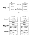
- FIG 3 illustrates a logical representation of entities E1, E2 according to the invention.
- Entities E1, E2 are each described by a set of alphanumeric descriptive data CD 1 (E1) -CD N (E1), CD 1 (E2) M-CD (E2), and maintain relationships one with the other, the relations being described by alphanumeric relationship data R (E1 ⁇ E2) , R (E2 ⁇ E1) .
- the relationships are oriented and include a starting entity and an ending entity.
- the entity E1 is the person "Dupont Jacques", described by his name and his first name
- the entity E2 is the company "SNBF", described by its name and the address of its head office
- the logical representation is augmented by numerical objects Obj (C (E1)), Obj (C (E2)) corresponding to entities C (E1), C (E2) qualifying concepts whose particular entities E1, E2 are instances.
- a numerical object Obj (C (E1)) corresponding to the concept C (E1) of "person”, whose entity E1 "Dupont Jacques” is an instance is created.
- a numerical object Obj (C (E2)) corresponding to the concept C (E2) of "society”, whose entity E2 "SNBF” is an instance is created.
- Each of the objects Obj (C (E1)), Obj (C (E2)) also includes a unique identifier id (C (E2)), id (C (E2)), and at least one pair consisting of an attribute qualifying the name of the object and the description of the concept. For example, concerning the concept object of "person", the digital object includes the couple (name, person).
- Each of the digital objects Obj (E1), Obj (E2), whose entities E1, E2 are the instances of the concepts C (E1), C (E2), are further complemented by a pair consisting of a membership attribute " ⁇ " and the identifier of the objective digital object Obj (C (E1)), Obj (C (E2)) corresponding.
- the introduction of concepts in the logical representation of the data makes it possible to add semantic content, and consequently to manipulate the data by means of semantic searches.
- the "concept" entities C (E1), C (E2) and the entity entities E1, E2 are identically stored and manipulated in an identical manner, which allows great flexibility, as will be explained more in details afterwards.
- figure 4 illustrates the logical representation of the information illustrated in figure 1 .
- alphanumeric data contained in digital objects is stored in a single table.
- the table includes an " object identifier " column, a " given code " column, an " attribute " column, an “attribute value " column and a " relational object identifier " column and each numerical object Obj (E1), Obj (E2) Obj (C (E1)), Obj (C (E2)) is then stored line by line in said table.
- a row of the table is created with the identifier of the object stored in the " object identifier " column. ", The attribute stored in the” attribute “column, the value of the attribute stored in the " attribute value " column.
- the entity description data stored in the created line is furthermore identified by a predetermined code, for example the word " description ", recorded in the " given code " column.
- a predetermined code for example the word " description ", recorded in the " given code " column.
- FIG. figure 6 is a unique table obtained by the storage on a computer medium of the digital objects of the figure 3B .
- the table of the figure 6 includes optional columns " date given ", which stores the date and time of the creation of the lines, " given status " which stores the status of the data stored in the lines, the value "1” meaning that the data are in life and the value "0” meaning that the data are no longer valid or are "inactive".
- the column "given code” makes it possible to reduce the number of lines interrogated by limiting the interrogation to only lines comprising the code "relation " when it is looked for the entities linked by relations during an access to the table .
- the code given "description" makes it possible to limit the query of the table to only lines comprising this code when descriptive entity data are only searched for when accessing the table.
- the database according to the invention makes it possible to store data relating to new entities and / or new relationships in a very simple manner, the corresponding update of the table consisting of the addition of lines.
- the single table only stores alpha-numeric data but not digital files.
- the table is thus limited in weight and is easily transportable.
- the management of the files, whatever the type of these (text file, audio, video, etc.), is carried out by defining a " location " attribute and giving as value for this attribute the path access to the physical location where the file is stored. It may for example be a location on a computer medium, an address on a communication network, for example internet, or others.
- a limited number of bytes is allocated per type of information stored in the table, for example an equal number of bytes by all boxes of the table.
- some alphanumeric information requires a large number of bytes to be fully memorized. This is for example the case of geolocation data.
- the solution consisting in providing a sufficient number of bytes, for example for the boxes of the "attribute" column or the boxes of a "geolocation" column specifically intended for the storage of this type of data therefore leads to a space of storage allocated to the table that is important.
- each data is characterized by attribute " location " and an attribute value consisting of a pointer to the data or a path to the physical location where it is stored. It is thus possible to reduce the allocation of space to the table by allocating a reduced number of bytes per box of the table or by type of information.
- a specific " data code " is defined, for example " internal link ".
- this information is also characterized by a specific " data code ", for example " external link ".
- data code for example " external link
- the figure 9 is a schematic view of an exemplary computer system embodying the invention.
- Such a system comprises for example a database server 50 comprising, or being connected to, a computer medium 52 memorizing the table 54 according to the invention, for example a hard disk, a SSD-type memory, or the like.
- the database is queried and / or updated with the server 50, for example provided with a man-machine interface, or by remote means, such as a personal computer 56, a tablet or smarphone 58 , connected to the server 50 by a communications network, eg the internet or VPN, and provided with a man-machine interface for querying and / or updating of the table 54.
- a communications network eg the internet or VPN
- the computer system may also include a computer support 60, 62 for storing the computer files referenced in the table, either the support 52 itself or different media connected to the server 50 directly or through other servers 64.
- the table 54 can be duplicated on another computer medium 66, for example for reasons of backup or access to its contents when the table stored in the medium 52 is not accessible, and to be synchronized to the support table 52 by means of data cloud type 68 ("cloud").
Abstract
Un système informatique comprend une mémoire informatique comportant une base de données alphanumériques décrivant un ensemble d'entités et des relations entre des couples d'entités dudit ensemble. Un objet numérique est créé pour chaque entité et chaque objet numérique comprend un identifiant unique, chaque couple d'attribut d'entité et de valeur d'attribut d'entité de l'entité dudit objet et pour chaque relation entre l'entité dudit objet et une autre entité, un couple constitué de l'attribut de la relation et de l'identifiant de l'objet associé à l'autre entité ; Les données alphanumériques de la base de données sont mémorisées dans une table unique comportant, pour chaque objet numérique : - une ligne pour chaque couple dudit objet constitué d'un attribut d'entité et d'une valeur d'attribut d'entité, ladite ligne comprenant l'identifiant unique dudit objet et ledit attribut et ladite valeur d'attribut dudit couple; et - une ligne pour chaque couple dudit objet constitué d'un attribut de relation et d'un identifiant, ladite ligne comprenant l'identifiant unique de l'objet, ledit attribut et ledit identifiant dudit couple.A computer system includes a computer memory having an alphanumeric database describing a set of entities and relationships between pairs of entities of said set. A digital object is created for each entity and each digital object comprises a unique identifier, each pair of entity attribute and entity attribute value of the entity of said object and for each relationship between the entity of said object. and another entity, a pair consisting of the attribute of the relation and the identifier of the object associated with the other entity; The alphanumeric data of the database are stored in a single table comprising, for each digital object: a line for each pair of said object consisting of an entity attribute and an entity attribute value, said line comprising the unique identifier of said object and said attribute and said attribute value of said pair; and a line for each pair of said object consisting of a relationship attribute and an identifier, said line comprising the unique identifier of the object, said attribute and said identifier of said pair.
Description
L'invention concerne le domaine du stockage des données informatiques, et plus particulièrement les bases de données.The invention relates to the field of storage of computer data, and more particularly the databases.
Comme cela est connu en soi, une base de données dite « relationnelle » permet de stocker sur un support informatique des données modélisées selon une relation logique particulière. La base de données relationnelle permet notamment de séparer la représentation logique des données de la manière dont elles sont effectivement structurées et mémorisées sur un support informatique.As is known per se, a so-called "relational" database makes it possible to store on a computer medium data modeled according to a particular logical relationship. The relational database makes it possible in particular to separate the logical representation of the data in the manner in which they are actually structured and stored on a computer medium.
Par exemple, la
Le codage de ces informations dans une base de données relationnelle est réalisé sous la forme d'une pluralité tables. Notamment, une table est créée pour chaque type d'entité et pour chaque type de relation. Par exemple, en se référant à la
Une base de données relationnelle permet également la mise en oeuvre d'opérations logiques d'algèbre relationnelle afin de manipuler son contenu. Notamment, l'exploitation du contenu de la base de données est réalisée au moyen d'un moteur de recherche, plus connu sous le nom de système de gestion de base de données (SGBD), permettant des opérations de jointure, de sélection et de projection. Un langage informatique couramment utilisé pour formuler des requêtes d'algèbre relationnelle sur la base de données est par exemple le langage SQL (pour « Structure Query Language »).A relational database also allows the implementation of logical relational algebra operations in order to manipulate its content. In particular, the exploitation of the contents of the database is carried out by means of a search engine, better known by the name of database management system (DBMS), allowing operations of join, selection and projection. A computer language commonly used to formulate relational algebra queries on the database is, for example, the SQL language (for " Structure Query Language ").
L'opération de jointure consiste notamment dans une même requête à indiquer plusieurs tables dans laquelle une information est recherchée. Par exemple, une demande visant à savoir pour quelle société travaille « Dupont Jacques », est transformée en au moins deux opération de jointure, la première impliquant la table « personne » 10 et la table « travail pour » 16, et une seconde impliquant la table «travaille pour » 16 et la table « société » 16, chacune des opérations résultant en une table temporaire qu'il convient encore d'interroger.The join operation consists in particular in the same request to indicate several tables in which information is sought. For example, a request to find out which company is working for "Dupont Jacques" is transformed into at least two join operations, the first involving the "person" table 10 and the "work for" table 16, and a second involving the table "works for" 16 and the "society" table 16, each of the operations resulting in a temporary table that still needs to be interrogated.
D'une manière générale, le nombre d'accès aux tables mémorisées dépend du nombre et la nature des relations qu'entretiennent les entités entre elle. On observe ainsi que les bases de données relationnelles gèrent de manière insuffisante les relations en raison de la structure tabulaire de la mémorisation des données, les relations n'étant envisagées qu'uniquement sous la forme de «jointures internes» entre des tables. La récupération des données peut donc être compliquée et/ou consommatrice de ressources lorsque la requête est mal formulée ou lorsqu'il s'agit de caractériser les relations par des propriétés particulières. Notamment, lorsque les informations sont fortement hiérarchisées et les relations entre entités sont dissymétriques, une requête peut entrainer l'interrogation récursive des tables. On pourra par exemple se référer au document
Un autre inconvénient des bases de données relationnelles est que la structure des données mémorisées sur le support informatique est fixée a priori. Il est donc compliqué de rajouter de nouveau champs, ou « attributs », décrivant les entités ou de nouveaux types d'entité et de nouveau type de relations. Cela suppose en effet de revoir le codage des données sur le support informatique, notamment en rajoutant de nouvelles tables et/ou de nouvelles colonnes aux tables existantes, ce qui s'avère couteux et long.Another disadvantage of relational databases is that the structure of the data stored on the computer medium is fixed a priori. It is therefore complicated to add new fields, or "attributes", describing entities or new entity types and new relationship types. This supposes indeed to review the coding of the data on the computer support, in particular by adding new tables and / or new columns to the existing tables, which proves to be expensive and long.
Une solution mise en oeuvre pour pallier ces défauts est d'utiliser une architecture différente pour la mémorisation des données, et notamment les structures dites « NoSQL » (pour « Not only SQL ») dont l'unité logique n'est plus la table de données. Si les bases de données NoSQL présentent donc un certain nombre d'avantages, elles sont cependant fortement dépendantes de leur usage et du type de données qu'elles mémorisent. Notamment, lors de la construction d'une base de données NoSQL, il convient de choisir malgré tout une architecture particulière, soit centrée sur les entités, soit centrée sur leur relation, de sorte que l'évolution de la base de données sur une nouvelle architecture est difficile.A solution implemented to overcome these defects is to use a different architecture for the storage of data, and in particular the structures called "NoSQL" (for " Not only SQL ") whose logical unit is no longer the table of data. While NoSQL databases have a number of advantages, they are highly dependent on their use and the type of data they store. In particular, when building a NoSQL database, a particular architecture must be chosen, either centered on the entities, or centered on their relationship, so that the evolution of the database on a new architecture is difficult.
Le but de la présente invention est de proposer une base de données dont l'architecture ne privilégie ni les entités ni leur relation, et dont la manipulation du contenu peut être réalisée à l'aide d'un nombre limité d'opérations.The purpose of the present invention is to propose a database whose architecture does not privilege the entities or their relationship, and whose manipulation of the content can be achieved using a limited number of operations.
A cet effet, l'invention a pour objet un système informatique comprenant :
- une mémoire informatique comportant une base de données alphanumériques décrivant un ensemble d'entités et des relations entre des couples d'entités dudit ensemble, chaque entité étant décrite par au moins un couple constitué d'un attribut d'entité qualifiant un type d'information et d'une valeur de l'attribut d'entité, et chaque relation entre deux entités étant décrite par au moins un attribut de relation qualifiant un type de lien entre les deux entités;
- une unité centrale, connectée à la mémoire informatique, apte à exécuter un moteur de recherche pour interroger la base de données en fonction de requêtes d'interrogation et pour fournir le résultat des recherches ; et
- une interface, connectée à l'unité centrale, pour entrer les requêtes d'interrogation et pour communiquer les résultats des recherches fournies par le moteur de recherche.
- a computer memory comprising an alphanumeric database describing a set of entities and relationships between pairs of entities of said set, each entity being described by at least one pair consisting of an entity attribute qualifying a type of information and a value of the entity attribute, and each relationship between two entities being described by at least one relationship attribute qualifying a type of link between the two entities;
- a central unit, connected to the computer memory, capable of executing a search engine for querying the database according to query requests and for providing the result of the searches; and
- an interface, connected to the central unit, to enter the query requests and to communicate the search results provided by the search engine.
Selon l'invention :
- un objet numérique est créé pour chaque entité de l'ensemble d'entités, chaque objet numérique d'entité créé étant référencé par un identifiant unique, et chaque objet numérique comprenant :
- ■ l'identifiant unique dudit objet ;
- ■ chaque couple d'attribut d'entité et de valeur d'attribut d'entité de l'entité dudit objet ; et
- ■ pour chaque relation entre l'entité dudit objet et une autre entité, un couple constitué de l'attribut de la relation et de l'identifiant de l'objet associé à l'autre entité ;
- les données alphanumériques de la base de données sont mémorisées dans une table unique comportant, pour chaque objet numérique :
- ■ une ligne pour chaque couple dudit objet constitué d'un attribut d'entité et d'une valeur d'attribut d'entité, ladite ligne comprenant l'identifiant unique dudit objet et ledit attribut et ladite valeur d'attribut dudit couple; et
- ■ une ligne pour chaque couple dudit objet constitué d'un attribut de relation et d'un identifiant, ladite ligne comprenant l'identifiant unique de l'objet, ledit attribut et ledit identifiant dudit couple.
- a digital object is created for each entity of the set of entities, each created entity digital object being referenced by a unique identifier, and each digital object comprising:
- ■ the unique identifier of the object;
- Each pair of entity attribute and entity attribute value pair of the entity of said object; and
- For each relationship between the entity of said object and another entity, a pair consisting of the attribute of the relation and the identifier of the object associated with the other entity;
- the alphanumeric data of the database are stored in a single table comprising, for each digital object:
- A line for each pair of said object consisting of an entity attribute and an entity attribute value, said line comprising the unique identifier of said object and said attribute and said attribute value of said pair; and
- A line for each pair of said object consisting of a relationship attribute and an identifier, said line comprising the unique identifier of the object, said attribute and said identifier of said pair.
En d'autres termes, tout d'abord la représentation logique des données est réalisée en fonction d'unités logiques, appelés « objets numériques », une unité logique rassemblant l'ensemble des données relatives à une entité, à savoir la description et les relations de l'entité. Un objet numérique est donc à la fois une entité et des relations impliquant celle-ci. Ensuite, la base de données selon l'invention, se fondant sur cette représentation, mémorise dans une table unique lesdits objets ligne par ligne. Ainsi, il n'y a aucune préférence entre les données décrivant les entités et les données décrivant leurs relations, et il n'existe plus de jointures internes dans la base de données.In other words, first of all the logical representation of the data is done according to logical units, called "digital objects", a logical unit gathering all the data relating to an entity, namely the description and the relationships of the entity. A digital object is both an entity and relationships involving it. Then, the database according to the invention, based on this representation, stores in a single table said objects line by line. Thus, there is no preference between the data describing the entities and the data describing their relationships, and there are no longer any internal joins in the database.
La récupération des données concernant une entité, à savoir les données décrivant l'entité et les données décrivant les relations impliquant celles-ci, peut ainsi être réalisée de manière simple et invariante en un nombre limité et constant de recherches, ou requête, élémentaires.The recovery of the data concerning an entity, namely the data describing the entity and the data describing the relationships involving them, can thus be realized in a simple and invariant manner in a limited and constant number of searches, or query, elementary.
Par ailleurs, une unité logique est elle-même décrite à l'aide de couples unitaires, à savoir un attribut et une valeur d'attribut pour les données descriptives de l'entité, et un attribut et un lien vers une autre entité pour les données concernant les relations de l'entité. L'ajout de données concernant un nouveau type d'entité se fait donc simplement en définissant un nouvel objet numérique, et en ajoutant des lignes correspondantes à la table. De même, l'ajout dans la base de données de données d'un nouveau type pour des entités existantes ne nécessite pas de recoder la base de données, par exemple en lui prévoyant de nouvelles colonnes, mais simplement en ajoutant des lignes comportant un nouvel attribut.In addition, a logical unit is itself described using unit pairs, namely an attribute and an attribute value for the descriptive data of the entity, and an attribute and a link to another entity for the entities. data about the entity's relationships. Adding data about a new entity type is done simply by defining a new numeric object, and adding corresponding rows to the table. Likewise, adding a new type of data to the database for existing entities does not require recoding the database, for example by providing new columns, but simply by adding new rows. attribute.
En outre, il est également possible de très simplement prévoir une organisation sémantique des données, par exemple en introduisant des concepts dont les entités sont des instances, sans que cela suppose une structure particulière des données sur le support informatique mémorisant la base de données.In addition, it is also possible to very simply provide a semantic organization of the data, for example by introducing concepts whose entities are instances, without this requiring a particular structure of the data on the computer medium storing the database.
Selon des modes de réalisation, le système comprend une ou plusieurs des caractéristiques suivantes.In embodiments, the system includes one or more of the following features.
Le moteur de recherche est apte à mettre en oeuvre, en fonction d'une requête d'interrogation comportant une valeur d'attribut d'une entité :
- ■ une première recherche, dans la table unique, de la ligne comprenant la valeur d'attribut et la récupération de l'identifiant de l'objet numérique comportant la valeur d' attribut ; et
- ■ une deuxième recherche, dans la table unique, des lignes comportant l'identifiant récupéré.
- A first search, in the single table, of the line comprising the attribute value and the retrieval of the identifier of the digital object comprising the attribute value; and
- A second search, in the single table, of the lines comprising the retrieved identifier.
Des entités sont des fichiers informatiques mémorisées dans la mémoire informatique, et en ce que pour chaque fichier, la valeur de l'attribut de l'objet numérique associé audit fichier est un chemin d'accès dudit fichier dans mémoire informatique.Entities are computer files stored in the computer memory, and in that for each file, the value of the attribute of the digital object associated with said file is a path of said file in computer memory.
L'interface est apte à recevoir, et communiquer à l'unité centrale, des données alphanumériques comprenant au moins un couple constitué d'un attribut et d'une valeur d'attribut d'une nouvelle entité, et l'unité centrale est apte à exécuter un module de mise à jour de la base de données en créant un objet numérique pour la nouvelle entité, ledit objet comprenant un identifiant unique et le couple d'attribut et de valeur d'attribut communiqué, et en en ajoutant à la table unique une ligne constituée de l'identifiant unique et le couple dudit objet.The interface is capable of receiving, and communicating to the central unit, alphanumeric data comprising at least one pair consisting of an attribute and an attribute value of a new entity, and the central unit is capable of executing a database update module by creating a digital object for the new entity, said object comprising a unique identifier and the attribute and attribute value pair communicated, and adding it to the table unique a line consisting of the unique identifier and the pair of said object.
L'interface est apte à recevoir, et communiquer à l'unité centrale, des données alphanumériques concernant un couple d'un attribut et d'une valeur d'attribut d'une entité de l'ensemble d'entités, et l'unité centrale est apte à exécuter un module de mise à jour de la base de donnée en rajoutant une ligne à la table unique comprenant l'identifiant de l'objet numérique associé à l'entité et le couple d'attribut et de valeur d'attribut reçu via l'interface.The interface is adapted to receive, and communicate to the central unit, alphanumeric data concerning a pair of an attribute and an attribute value of an entity of the set of entities, and the unit central is able to execute a database update module by adding a row to the single table comprising the identifier of the digital object associated with the entity and the attribute and attribute value pair received via the interface.
L'interface est apte à recevoir, et communiquer à l'unité centrale, des données alphanumériques concernant un attribut de relation entre une entité de l'ensemble de l'entité et une autre entité de l'ensemble d'entités, et l'unité centrale est apte à exécuter un module de mise à jour de la base de donnée en rajoutant une ligne à la table unique comprenant l'identifiant de l'objet numérique associé à l'entité, l'attribut de la relation et l'identifiant de l'objet numérique associé à l'autre entité.The interface is adapted to receive, and communicate to the central unit, alphanumeric data relating to a relationship attribute between an entity of the whole entity and another entity of the entity set, and the CPU is able to run a database update module by adding a row to the single table comprising the identifier of the digital object associated with the entity, the attribute of the relation and the identifier of the digital object associated with the other entity.
La table unique comporte une colonne d'horodatage comprenant la date de création de chaque ligne de la table.The unique table has a timestamp column that includes the creation date for each row in the table.
La table unique comporte une colonne de statut comprenant la valeur d'un statut pour chaque ligne, ledit statut décrivant l'état actif ou inactif de ladite ligne.The single table includes a status column including the value of a status for each line, said status describing the active or inactive state of said line.
Des entités concernent des concepts et des entités concernent des instances desdits concepts, l'objet numérique d'une entité concernant une instance de concept étant relié à un objet numérique concernant le concept de l'instance par une relation d'appartenance.Entities concern concepts and entities concern instances of said concepts, the digital object of an entity concerning a concept instance being connected to a digital object concerning the concept of the instance by a membership relation.
L'invention sera mieux comprise à la lecture de la description qui va suivre, donnée uniquement à titre d'exemple, et faire en relation avec les dessins annexés, dans lesquels :
- la
figure 1 est un exemple d'entités et de relations qu'entretiennent les entités ; - la
figure 2 est une vue schématique des tables d'une base de données relationnelle de l'état de la technique, utilisées pour stocker sur un support informatique les données relatives aux entités et aux relations de lafigure 1 ; - les
figures 3A et 3B illustrent la représentation logique d'information par des objets numériques selon l'invention ; - la
figure 4 illustre la représentation logique de l'invention des informations décrites à lafigure 1 ; - la
figure 5 est un exemple de table unique stockant des objets numériques de lafigure 3 ; - la
figure 6 est un exemple de table stockant les objets numériques de lafigure 4 ; - les
figures 7 illustrent l'ajout de données concernant un nouveau type d'entité aux données déjà existante de la base de données selon l'invention, par exemple des données relatives à des documents - les
figures 8 illustrent l'ajout d'un nouveau type de données descriptives aux données déjà existantes de la base de données selon l'invention, par exemple un numéro de téléphone et une date de naissance ; et - la
figure 9 est une vue schématique d'un système informatique selon l'invention.
- the
figure 1 is an example of entities and relationships that entities maintain; - the
figure 2 is a schematic view of the tables of a relational database of the state of the art, used to store on a computer medium the data relating to the entities and the relations of thefigure 1 ; - the
Figures 3A and 3B illustrate the logical representation of information by digital objects according to the invention; - the
figure 4 illustrates the logical representation of the invention of the information described infigure 1 ; - the
figure 5 is an example of a single table storing digital objects from thefigure 3 ; - the
figure 6 is an example of a table storing digital objects from thefigure 4 ; - the
figures 7 illustrate the addition of data concerning a new type of entity to the already existing data of the database according to the invention, for example data relating to documents - the
figures 8 illustrate the addition of a new type of descriptive data to the already existing data of the database according to the invention, for example a telephone number and a date of birth; and - the
figure 9 is a schematic view of a computer system according to the invention.
La
Comme illustré à la
- a. un identifiant unique id(E1), différent des identifiants des autres objets numériques, par exemple un numéro;
- b. pour chaque donnée descriptive CD1(E1)-CDN(E1) de l'entité E1, un couple constitué d'un attribut att1(E1)-attN(E1) de ladite donnée et ladite donnée, l'attribut qualifiant une catégorie à laquelle la donnée appartient, ou, dit autrement, un type de données ou un concept dont la donnée descriptive est une instance. Par exemple, l'attribut de la donnée descriptive « Dupont » est le concept de « nom ». La donnée « Dupont » est ainsi représentée dans l'objet numérique par le couple (nom, Dupont) ; et
- c. pour chaque relation dont l'entité E1 est le point de départ, un couple constitué d'un attribut de relation, à savoir la donnée de relation R(E1→E2), et de l'identifiant id(E2) de l'entité d'arrivée E2 de la relation.
- at. a unique identifier id (E1), different from the identifiers of the other digital objects, for example a number;
- b. for each descriptive datum CD 1 (E1) -CD N (E1) of the entity E1, a pair consisting of an attribute att 1 (E1) -att N (E1) of said datum and said datum, the qualifying attribute a category to which the data belongs, or, in other words, a data type or a concept whose descriptive data is an instance. For example, the attribute of the descriptive data "Dupont" is the concept of "name". The data "Dupont" is thus represented in the digital object by the couple (name, Dupont); and
- vs. for each relation whose entity E1 is the starting point, a pair consisting of a relationship attribute, namely the relation data item R (E1 → E2), and the entity identifier id (E2) of the entity E2 arrival of the relationship.
De manière avantageuse et optionnelle, la représentation logique est augmentée par des objets numériques Obj(C(E1)), Obj(C(E2)) correspondant à des entités C(E1), C(E2) qualifiant des concepts dont les entités particulières E1, E2 sont des instances. Par exemple, un objet numérique Obj(C(E1)) correspondant au concept C(E1) de « personne », dont l'entité E1 « Dupont Jacques » est une instance, est créé. De même un objet numérique Obj(C(E2)) correspondant au concept C(E2) de « société », dont l'entité E2 « SNBF » est une instance, est créé. Chacun des objets Obj(C(E1)), Obj(C(E2)) comporte également un identifiant unique id(C(E2)), id(C(E2)), ainsi qu'au moins un couple constitué d'un attribut qualifiant le nom de l'objet et la description du concept. Par exemple, concernant l'objet concept de « personne », l'objet numérique comporte le couple (nom, personne). Chacun des objets numériques Obj(E1), Obj(E2), dont les entités E1, E2 sont les instances des concepts C(E1), C(E2), sont par ailleurs complétés par un couple constitué d'un attribut d'appartenance « ∈ » et de l'identifiant de l'objet numérique de concept Obj(C(E1)), Obj(C(E2)) correspondant. Comme cela est connu en soi, l'introduction de concepts dans la représentation logique des données permet d'ajouter un contenu sémantique, et par conséquent de manipuler les données au moyen de recherche sémantiques. Selon l'invention, les entités « concepts » C(E1), C(E2) et les entités instances E1, E2 sont stockées de manière identique et manipulées de manière identique, ce qui permet une grande souplesse, comme cela sera expliqué plus en détails par la suite.Advantageously and optionally, the logical representation is augmented by numerical objects Obj (C (E1)), Obj (C (E2)) corresponding to entities C (E1), C (E2) qualifying concepts whose particular entities E1, E2 are instances. For example, a numerical object Obj (C (E1)) corresponding to the concept C (E1) of "person", whose entity E1 "Dupont Jacques" is an instance, is created. Similarly a numerical object Obj (C (E2)) corresponding to the concept C (E2) of "society", whose entity E2 "SNBF" is an instance, is created. Each of the objects Obj (C (E1)), Obj (C (E2)) also includes a unique identifier id (C (E2)), id (C (E2)), and at least one pair consisting of an attribute qualifying the name of the object and the description of the concept. For example, concerning the concept object of "person", the digital object includes the couple (name, person). Each of the digital objects Obj (E1), Obj (E2), whose entities E1, E2 are the instances of the concepts C (E1), C (E2), are further complemented by a pair consisting of a membership attribute "∈" and the identifier of the objective digital object Obj (C (E1)), Obj (C (E2)) corresponding. As is known per se, the introduction of concepts in the logical representation of the data makes it possible to add semantic content, and consequently to manipulate the data by means of semantic searches. According to the invention, the "concept" entities C (E1), C (E2) and the entity entities E1, E2 are identically stored and manipulated in an identical manner, which allows great flexibility, as will be explained more in details afterwards.
Bien que la représentation logique selon l'invention ait été illustrée à l'aide de deux entités, on comprend aisément que cette représentation s'applique à n'importe quel nombre d'entités et de relations. Par exemple, la
Il va à présent être décrit la manière dont sont stockées les données sur un support informatique, la structure de stockage étant liée à la représentation logique précédemment décrite.It will now be described how the data is stored on a computer medium, the storage structure being related to the previously described logical representation.
Plus particulièrement, comme illustrée à la
Bien entendu, le nom donné aux colonnes importe peu et la colonne « identifiant objet relation » pourrait être fusionnée avec la colonne « valeur attribut ». De même, il est possible de prévoir plusieurs colonnes « valeur attribut » en fonction de la nature des données afin de faciliter la gestion et la manipulation de la table unique. D'autres colonnes comportant des données complémentaires peuvent également être prévues, comme cela est par exemple illustré à la
Grâce à la représentation logique des données et de leur mémorisation sous forme de table unique, il est possible de récupérer des données relatives à une entité de manière invariante, quel que soit la nature et le nombre de relations dans laquelle elle est impliquée.Thanks to the logical representation of the data and its storage as a single table, it is possible to recover data relating to an entity in an invariant way, whatever the nature and the number of relations in which it is involved.
Notamment, il est possible de récupérer l'ensemble des données d'une entité en seulement deux accès à la table unique, contrairement aux bases de données relationnelles de l'état de la technique dont le nombre d'accès est variable et parfois récursif. Par exemple, la récupération des données relatives à « Dupont Jacques », à savoir les données descriptives de celui-ci, mais également les relations qu'il entretient avec d'autres entités et identifiant de ces autres entités, ne nécessite que deux accès à la table selon l'invention, à savoir un premier accès à la table pour récupérer l'identifiant de l'objet numérique lié à « Dupont Jacques », et un deuxième accès à la table pour extraire l'ensemble des lignes comprenant l'identifiant récupéré. En se référant à la base de données relationnelle de l'état de la technique illustrée à la
En outre, la colonne « code donnée » permet de réduire le nombre de lignes interrogées en limitant l'interrogation aux seules lignes comportant le code « relation » lorsqu'il est recherché les entités liées par des relations lors d'un accès à la table. De même, le code donné « description » permet de limiter l'interrogation de la table aux seules lignes comprenant ce code lorsque des données descriptives d'entité sont uniquement recherchées lors d'un accès à la table.In addition, the column "given code " makes it possible to reduce the number of lines interrogated by limiting the interrogation to only lines comprising the code "relation " when it is looked for the entities linked by relations during an access to the table . Similarly, the code given "description " makes it possible to limit the query of the table to only lines comprising this code when descriptive entity data are only searched for when accessing the table.
Par ailleurs, la base de données selon l'invention permet le stockage de données concernant de nouvelles entités et /ou de nouvelles relations de manière très simple, la mise à jour correspondante de la table consistant en l'ajout de lignes.Furthermore, the database according to the invention makes it possible to store data relating to new entities and / or new relationships in a very simple manner, the corresponding update of the table consisting of the addition of lines.
Par exemple, en se référant aux
De manière avantageuse, la table unique ne stocke que des données alpha-numériques mais pas de fichiers numériques. La table reste ainsi limitée en poids et est facilement transportable. De manière avantageuse et optionnelle, la gestion des fichiers, quel que soit le type de ceux-ci (fichier texte, audio, vidéo, etc), est réalisée en définissant un attribut « emplacement » et en donnant comme valeur pour cet attribut le chemin d'accès à l'emplacement physique où est mémorisé le fichier. Il peut par exemple s'agir d'un emplacement sur un support informatique, d'une adresse sur un réseau de communication, par exemple internet, ou autres.Advantageously, the single table only stores alpha-numeric data but not digital files. The table is thus limited in weight and is easily transportable. Advantageously and optionally, the management of the files, whatever the type of these (text file, audio, video, etc.), is carried out by defining a " location " attribute and giving as value for this attribute the path access to the physical location where the file is stored. It may for example be a location on a computer medium, an address on a communication network, for example internet, or others.
De manière optionnelle, afin de réduire le poids de la table, et donc par exemple augmenter sa portabilité, un nombre limité d'octets est alloué par type d'information mémorisée dans la table, par exemple un nombre égal d'octets par toutes les cases de la table. En effet, certaines informations alphanumériques requièrent un nombre important d'octets pour pouvoir être entièrement mémorisées. C'est par exemple le cas des données de géolocalisation. La solution consistant à prévoir un nombre d'octets suffisant, par exemple pour les cases de la colonne « attribut » ou les cases d'une colonne « géolocalisation » spécifiquement prévue pour le stockage de ce type de données, mène donc à un espace de stockage alloué à la table qui est important. Afin de réduire cet espace, les données alphanumériques nécessitant beaucoup d'octets sont mémorisées ailleurs que dans la table elle-même, par exemple dans une table prévue à cet effet, et la table selon l'invention comprend des liens vers lesdites données. Par exemple, chaque donnée est caractérisée par attribut « emplacement » et une valeur d'attribut constituée d'un pointeur vers la données ou un chemin d'accès à l'emplacement physique où elle est stockée. Il est ainsi possible de réduire l'allocation d'espace à la table en allouant un nombre réduit d'octets par case de la table ou par type d'information. De préférence, pour ce type de lien à l'intérieur même de la base de données, il est défini un « code données » spécifique, par exemple « internal link ». On note par ailleurs que la construction d'une ou plusieurs tables supplémentaires n'est pas dictée par la représentation des données et/ou les liens qui existent entre elles, mais par des considérations de gestion de mémoire. La table centrale de l'invention reste donc le moyen principal de stockage des données selon le modèle de représentation décrit précédemment.Optionally, in order to reduce the weight of the table, and therefore for example increase its portability, a limited number of bytes is allocated per type of information stored in the table, for example an equal number of bytes by all boxes of the table. Indeed, some alphanumeric information requires a large number of bytes to be fully memorized. This is for example the case of geolocation data. The solution consisting in providing a sufficient number of bytes, for example for the boxes of the "attribute" column or the boxes of a "geolocation" column specifically intended for the storage of this type of data, therefore leads to a space of storage allocated to the table that is important. In order to reduce this space, alphanumeric data requiring many bytes are stored elsewhere than in the table itself, for example in a table provided for this purpose, and the table according to the invention comprises links to said data. For example, each data is characterized by attribute " location " and an attribute value consisting of a pointer to the data or a path to the physical location where it is stored. It is thus possible to reduce the allocation of space to the table by allocating a reduced number of bytes per box of the table or by type of information. Preferably, for this type of link within the database itself, a specific " data code " is defined, for example " internal link ". Note also that the construction of one or more additional tables is not dictated by the representation of the data and / or the links that exist between them, but by memory management considerations. The central table of the invention therefore remains the main means of storing data according to the representation model described above.
De même, concernant les informations non alphanumériques stockées hors de la base de données, par exemple les fichiers décrits précédemment, ces informations sont également caractérisées par un « code données » spécifique, par exemple « external link ». Ceci permet notamment de différentier les deux types de lien gérés par la table, à savoir les liens internes et les liens externes à la base de données.Similarly, concerning the non-alphanumeric information stored outside the database, for example the files described above, this information is also characterized by a specific " data code ", for example " external link ". This In particular, it makes it possible to differentiate the two types of link managed by the table, namely the internal links and the external links to the database.
De plus, l'ajout de données descriptives d'un nouveau type pour des entités déjà existantes se fait également très simplement. Par exemple, en se référant aux
La
Un tel système comporte par exemple un serveur de base de données 50 comprenant, ou étant connecté à, un support informatique 52 mémorisant la table 54 selon l'invention, par exemple un disque dur, une mémoire de type SSD, ou autres. La base de données est interrogée et/ou mise à jour à l'aide du serveur 50, par exemple muni d'une interface homme machine, ou par des moyens distants, comme par exemple un ordinateur personnel 56, une tablette ou un smarphone 58, connectés au serveur 50 par un réseau de communication, par exemple du type internet ou VPN, et munis d'une interface homme machine permettant l'interrogation et/ou la mise à jour de la table 54. Le système informatique peut également comprendre un support informatique 60, 62 pour la mémorisation des fichiers informatiques référencés dans la table, soit le support 52 lui-même ou des supports différents connectés au serveur 50 directement ou au travers d'autres serveurs 64. Par ailleurs, la table 54 peut être dupliquée sur un autre support informatique 66, par exemple pour des raisons de sauvegarde ou d'accès à son contenu lorsque la table mémorisée dans le support 52 n'est pas accessibles, et être synchronisée à la table du support 52 par des moyens de type nuage de données 68 (« cloud »).Such a system comprises for example a
Claims (9)
Priority Applications (2)
| Application Number | Priority Date | Filing Date | Title |
|---|---|---|---|
| EP13306664.7A EP2881865A1 (en) | 2013-12-04 | 2013-12-04 | Computer system comprising a database stored in table form |
| PCT/EP2014/076533 WO2015082593A1 (en) | 2013-12-04 | 2014-12-04 | Computer system comprising a database stored in table form |
Applications Claiming Priority (1)
| Application Number | Priority Date | Filing Date | Title |
|---|---|---|---|
| EP13306664.7A EP2881865A1 (en) | 2013-12-04 | 2013-12-04 | Computer system comprising a database stored in table form |
Publications (1)
| Publication Number | Publication Date |
|---|---|
| EP2881865A1 true EP2881865A1 (en) | 2015-06-10 |
Family
ID=49989450
Family Applications (1)
| Application Number | Title | Priority Date | Filing Date |
|---|---|---|---|
| EP13306664.7A Withdrawn EP2881865A1 (en) | 2013-12-04 | 2013-12-04 | Computer system comprising a database stored in table form |
Country Status (2)
| Country | Link |
|---|---|
| EP (1) | EP2881865A1 (en) |
| WO (1) | WO2015082593A1 (en) |
Citations (1)
| Publication number | Priority date | Publication date | Assignee | Title |
|---|---|---|---|---|
| US20100223296A1 (en) * | 1998-09-04 | 2010-09-02 | Kalido Limited | Data Processing System |
-
2013
- 2013-12-04 EP EP13306664.7A patent/EP2881865A1/en not_active Withdrawn
-
2014
- 2014-12-04 WO PCT/EP2014/076533 patent/WO2015082593A1/en active Application Filing
Patent Citations (1)
| Publication number | Priority date | Publication date | Assignee | Title |
|---|---|---|---|---|
| US20100223296A1 (en) * | 1998-09-04 | 2010-09-02 | Kalido Limited | Data Processing System |
Non-Patent Citations (11)
| Title |
|---|
| "CHAPTER 2: Database System Concepts and Architecture ED - Elmasri R; Navathe S B (Eds)", 1 January 2011, FUNDAMENTALS OF DATABASE SYSTEMS (SIXTH EDITION),, PAGE(S) 29 - 55, ISBN: 978-0-13-608620-8, XP009171284 * |
| "CHAPTER 3: The Relational Data Model and Relational Database Constraints ED - Ramez Elmasri; Shamkant B Navathe (eds)", 1 January 2011, FUNDAMENTALS OF DATABASE SYSTEMS (SIXTH EDITION), ADDISON-WESLEY, PAGE(S) 59 - 85, ISBN: 978-0-13-608620-8, XP009171285 * |
| "Kalido Information Engine Resources | Kalido", 13 May 2013 (2013-05-13), XP055111947, Retrieved from the Internet <URL:http://wayback.archive.org/web/20130513105600/http://www.kalido.com/resource-center-information-engine.htm> [retrieved on 20140403] * |
| ANONYMOUS: "sql - Key/Value pairs in a database table - Stack Overflow", 3 April 2013 (2013-04-03), XP055111530, Retrieved from the Internet <URL:http://wayback.archive.org/web/20130403044610/http://stackoverflow.com/questions/514603/key-value-pairs-in-a-database-table> [retrieved on 20140402] * |
| ANONYMOUS: "Sturnus: The Curse Of The Name-Value Pair", 3 January 2013 (2013-01-03), XP055111518, Retrieved from the Internet <URL:http://wayback.archive.org/web/20130103113523/http://www.sturnus.co.uk/performance/2008-07/the-curse-of-the-name-value-pair/?> [retrieved on 20140402] * |
| ANONYMOUS: "sys.sysobjects table (Transact-SQL)", 14 April 2006 (2006-04-14), XP055111594, Retrieved from the Internet <URL:http://technet.microsoft.com/fr-fr/library/ms177596(v=sql.90).aspx> [retrieved on 20140402] * |
| DAN COLLINS: "Generic Data Modeling", 27 December 2010 (2010-12-27), XP055111669, Retrieved from the Internet <URL:http://web.archive.org/web/20101227035908/http://oliver.efos.hr/nastavnici/jmesaric/modeliranje/P6_pomocni/Kalido_Generic_Data_Modeling.pdf> [retrieved on 20140402] * |
| DARREN GOSBELL: "Key Value Pairs in Database design", 4 July 2012 (2012-07-04), XP055111529, Retrieved from the Internet <URL:http://wayback.archive.org/web/20120704104353/http://geekswithblogs.net/darrengosbell/articles/KVPsInDatabaseDesign.aspx> [retrieved on 20140402] * |
| DR HAKAN SARBANOGLU: "Understanding Kalido Data Architecture A Technical Overview of a Kalido-Driven Business Model and Data Warehouse White Paper White Paper: Understanding Kalido Data Architecture", 13 May 2013 (2013-05-13), XP055111946, Retrieved from the Internet <URL:http://www.kalido.com/Collateral/Documents/English-US/WP-UnderstandingKalidoArch.pdf> [retrieved on 20140403] * |
| IAN ROBINSON ET AL.: "Graph Databases", 2013, O'REILLY MEDIA INC. |
| TIM GORMAN: "Bad CaRMa", 3 October 2013 (2013-10-03), XP055111581, Retrieved from the Internet <URL:http://wayback.archive.org/web/20131003172440/https://www.simple-talk.com/opinion/opinion-pieces/bad-carma/> [retrieved on 20140402] * |
Also Published As
| Publication number | Publication date |
|---|---|
| WO2015082593A1 (en) | 2015-06-11 |
Similar Documents
| Publication | Publication Date | Title |
|---|---|---|
| US11093466B2 (en) | Incremental out-of-place updates for index structures | |
| US10810191B2 (en) | Limiting scans of loosely ordered and/or grouped relations in a database | |
| US10769248B2 (en) | Satellite and central asset registry systems and methods and rights management systems | |
| US10176225B2 (en) | Data processing service | |
| Moniruzzaman et al. | Nosql database: New era of databases for big data analytics-classification, characteristics and comparison | |
| Grover et al. | Hadoop Application Architectures: Designing Real-World Big Data Applications | |
| US20120016901A1 (en) | Data Storage and Processing Service | |
| US10452714B2 (en) | Central asset registry system and method | |
| US9201700B2 (en) | Provisioning computer resources on a network | |
| FR2859552A1 (en) | Data extraction technique for database includes use of local database to collect requested data prior to spreadsheet display | |
| CN111221791A (en) | Method for importing multi-source heterogeneous data into data lake | |
| CN105164673A (en) | Query integration across databases and file systems | |
| US20230359627A1 (en) | Sharing compiled code for executing queries across query engines | |
| Kumar et al. | Modern Big Data processing with Hadoop: Expert techniques for architecting end-to-end Big Data solutions to get valuable insights | |
| EP3577587B1 (en) | Satellite and central asset registry systems and methods and rights management systems | |
| US11868445B2 (en) | Systems and methods for federated searches of assets in disparate dam repositories | |
| EP1895410A1 (en) | Method and system for extraction of a data table from a database and corresponding computer program product | |
| EP2881865A1 (en) | Computer system comprising a database stored in table form | |
| US20100205197A1 (en) | Two-valued logic database management system with support for missing information | |
| EP3991059A1 (en) | Systems and methods for federated searches of assets in disparate dam repositories | |
| Fong et al. | Toward a scale-out data-management middleware for low-latency enterprise computing | |
| Gupta et al. | Data lake ingestion strategies | |
| Alam | Data Migration: Relational Rdbms To Non-Relational Nosql | |
| Nieva | Integrating heterogeneous data | |
| Olivier | Literature Review: Archiving Archives |
Legal Events
| Date | Code | Title | Description |
|---|---|---|---|
| PUAI | Public reference made under article 153(3) epc to a published international application that has entered the european phase |
Free format text: ORIGINAL CODE: 0009012 |
|
| 17P | Request for examination filed |
Effective date: 20131204 |
|
| AK | Designated contracting states |
Kind code of ref document: A1 Designated state(s): AL AT BE BG CH CY CZ DE DK EE ES FI FR GB GR HR HU IE IS IT LI LT LU LV MC MK MT NL NO PL PT RO RS SE SI SK SM TR |
|
| AX | Request for extension of the european patent |
Extension state: BA ME |
|
| R17P | Request for examination filed (corrected) |
Effective date: 20151030 |
|
| RBV | Designated contracting states (corrected) |
Designated state(s): AL AT BE BG CH CY CZ DE DK EE ES FI FR GB GR HR HU IE IS IT LI LT LU LV MC MK MT NL NO PL PT RO RS SE SI SK SM TR |
|
| 17Q | First examination report despatched |
Effective date: 20170724 |
|
| STAA | Information on the status of an ep patent application or granted ep patent |
Free format text: STATUS: THE APPLICATION IS DEEMED TO BE WITHDRAWN |
|
| 18D | Application deemed to be withdrawn |
Effective date: 20171205 |