EP2881776A1 - Wide-angle projection optical system - Google Patents
Wide-angle projection optical system Download PDFInfo
- Publication number
- EP2881776A1 EP2881776A1 EP14153879.3A EP14153879A EP2881776A1 EP 2881776 A1 EP2881776 A1 EP 2881776A1 EP 14153879 A EP14153879 A EP 14153879A EP 2881776 A1 EP2881776 A1 EP 2881776A1
- Authority
- EP
- European Patent Office
- Prior art keywords
- optical system
- lens group
- wide
- projection optical
- angle projection
- Prior art date
- Legal status (The legal status is an assumption and is not a legal conclusion. Google has not performed a legal analysis and makes no representation as to the accuracy of the status listed.)
- Withdrawn
Links
Images








Classifications
-
- G—PHYSICS
- G02—OPTICS
- G02B—OPTICAL ELEMENTS, SYSTEMS OR APPARATUS
- G02B13/00—Optical objectives specially designed for the purposes specified below
- G02B13/16—Optical objectives specially designed for the purposes specified below for use in conjunction with image converters or intensifiers, or for use with projectors, e.g. objectives for projection TV
-
- G—PHYSICS
- G02—OPTICS
- G02B—OPTICAL ELEMENTS, SYSTEMS OR APPARATUS
- G02B13/00—Optical objectives specially designed for the purposes specified below
- G02B13/22—Telecentric objectives or lens systems
-
- G—PHYSICS
- G02—OPTICS
- G02B—OPTICAL ELEMENTS, SYSTEMS OR APPARATUS
- G02B17/00—Systems with reflecting surfaces, with or without refracting elements
- G02B17/08—Catadioptric systems
- G02B17/0856—Catadioptric systems comprising a refractive element with a reflective surface, the reflection taking place inside the element, e.g. Mangin mirrors
-
- G—PHYSICS
- G03—PHOTOGRAPHY; CINEMATOGRAPHY; ANALOGOUS TECHNIQUES USING WAVES OTHER THAN OPTICAL WAVES; ELECTROGRAPHY; HOLOGRAPHY
- G03B—APPARATUS OR ARRANGEMENTS FOR TAKING PHOTOGRAPHS OR FOR PROJECTING OR VIEWING THEM; APPARATUS OR ARRANGEMENTS EMPLOYING ANALOGOUS TECHNIQUES USING WAVES OTHER THAN OPTICAL WAVES; ACCESSORIES THEREFOR
- G03B21/00—Projectors or projection-type viewers; Accessories therefor
- G03B21/14—Details
- G03B21/28—Reflectors in projection beam
Definitions
- the present disclosure relates to a projection optical system, and more particularly to an ultra-short-throw or a wide-angle projection optical system.
- a wide-angle projection lens has a large field of view, or a short effective focal length (EFL).
- EFL effective focal length
- the projection display apparatus with a wide-angle projection lens is capable of producing a certain sized image at a shorter distance.
- FIG. 1A is a schematic diagram illustrating an integrated system of a projection display apparatus and an interactive white board according to the prior art.
- the projection display apparatus 10 is usually mounted upside down over the white board 11.
- the conventional short-throw projection display apparatus 10 is usually mounted at a distance of about 1 meter away from the white board 11.
- the lecturer with average height becomes an obstacle to the light path of the projection display apparatus 10 when writing on the white board 11.
- the eyes of the lecturer have the potential danger of being illuminated by the light from the projection display apparatus 10.
- the projection display apparatus 10 needs to be mounted in the vicinity of the white board 11. Since the projection distance is very short, the projection display apparatus 10 should have a wide-angle projection lens to provide a large full field angle ⁇ or a very short focal length. In a case that the projection display apparatus 10 with a wide-angle projection lens is mounted over the white board 11, the light flux needs to incident on the white board 11 at a very steep angle, which incurs a large distortion in the image. Moreover, the projection lens also needs to have a large offset to avoid the light hitting on the main body of the projection display apparatus, and avoid the body of reflecting mirror blocking the top area of the white board. In other words, the wide-angle or ultra-short projection lens is very critical for designing the projection display apparatus.
- FIG. 1C is a schematic diagram illustrating the configuration of a wide-angle projection optical system according to the prior art.
- the design uses two aspheric plastic lenses, one double concave negative lens and a negative aspheric reflecting mirror.
- the total length of the system is quite long. This makes it difficult to have a thin projector system.
- the maximum field angle is on the order of 55 degree, which still requires a fairly long projection distance to produce an image that is large enough for practical applications.
- FIG. 1D is a schematic diagram illustrating the configuration of another wide-angle projection optical system according to the prior art.
- US patent No. 7,048,388 disclosed a wide-angle projection lens design as shown in FIG. 1D that incorporates a flat mirror and a positive aspheric reflecting mirror.
- the optical components of the wide-angle projection optical system have to be tilted and decentered in arrangement for obtaining an undistorted image with better image quality. Otherwise, optical components having anamorphic polynomial free-form surfaces with different magnifications in vertical direction and horizontal direction are necessary to be used in the wide-angle projection optical system, and the complication of assembling or manufacturing optical components are increased.
- An another aspect of the present invention provides a wide-angle projection optical system with ultra-short-throw having a large full field angle, which is for example larger than 70 degrees, a short effective focal length, thin profile, low distortion and aberration and high image quality.
- a wide-angle projection optical system includes, between an object side and an image side, a first optical system including a first lens group having an aperture stop therein and a second lens group, and a second optical system including a Mangin mirror.
- the first lens group has positive power
- the second lens group has positive power.
- the first lens group provides optical characteristics to match with a light coming from the object side and converges the light toward the aperture stop.
- the second lens group is disposed behind the aperture stop.
- the first lens group and the second lens group are configured to form an aberrated real image in front of the Mangin mirror.
- the Mangin mirror is disposed closer to the image side than the first lens group, the aperture stop and the second lens group.
- the Mangin mirror includes a refracting surface and a reflecting surface for refracting the light two times and reflecting the light one time, thereby producing an enlarged real image on a screen.
- a wide-angle projection optical system includes, from an object side to an image side, a first optical system including a first lens group having an aperture stop therein and a second lens group, and a second optical system including a refracting and reflecting mirror with positive power.
- the first lens group has positive power
- the second lens group has positive power.
- the first lens group provides optical characteristics to match with a light coming from the object side and converges the light toward the aperture stop.
- the second lens group is disposed behind the aperture stop, and both surfaces of at least one lens of the second lens group are aspheric.
- the first lens group and the second lens group are configured to form an aberrated real image in front of the refracting and reflecting mirror with positive power.
- the refracting and reflecting mirror includes a refracting surface and a reflecting surface for refracting the light two times and reflecting the light one time, thereby producing an enlarged real image on a screen.
- the first lens group, the second lens group and the refracting and reflecting mirror have a common optical axis.
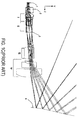
- FIG. 2 is a schematic diagram illustrating the configuration of a wide-angle projection optical system according to an embodiment of the present invention.
- the wide-angle projection optical system 2 is a non-telecentric projection optical system, which can be applied to a projection display apparatus.
- the projection display apparatus includes, but not limited to, a digital micromirror device (hereinafter "DMD").
- the DMD has an object surface 3, which is an image-displaying surface of a light valve.
- the object surface 3 is configured as an object side A for the image projected by the wide-angle projection optical system 2 of the present invention to be formed on.
- the wide-angle projection optical system 2 includes, between the object side A and an image side B, a first optical system 21 and a second optical system 22, among which the first optical system 21 and the second optical system 22 are configured to form the wide-angle projection optical system 2 as a non-telecentric wide-angle projection optical system.
- the first optical system 21 includes a first lens group 211 having positive power and including an aperture stop 212 and a second lens group 213 having positive power
- the second optical system 22 includes a Mangin mirror 221.
- the first lens group 211 sets up proper working space and pupil position to match with the illumination optical system.
- the first lens group 211 is configured to provide optical characteristics to match with a light coming from the object side A and converge the light toward the aperture stop 212, such that the light is further projected or outputted to the second lens group 213.
- the first lens group 211 of the wide-angle projection optical system 2 consists of a plurality of refraction lenses and has positive effective optical power for providing the telecentricity of object space and converging the light emitted toward the aperture stop 212 by the DMD.
- the aperture stop 212 is located in the first lens group 211 and at the focus point of the main light.
- the Mangin mirror 221 is disposed closer to the image side B than the first lens group 211, the aperture stop 212 and the second lens group 213. An aberrated real image is formed by the first lens group 211 and the second lens group 213.
- the Mangin mirror 221 includes a refracting surface 2211 and a reflecting surface 2212 for refracting the light two times and reflecting the light one time, thereby producing an enlarged real image on a screen in order to correct aberration and distortion. Therefore, the full field angle is enhanced, and the projection lens or the body of the projection display apparatus can be located between the reflecting mirror and the screen, thereby miniaturizing the integrated projection system.
- the first lens group 211, the aperture stop 212 and the second lens group 213 of the first optical system 21 and the Mangin mirror 221 of the second optical system 22 of the wide-angle projection optical system 2 of one embodiment of the present invention are arranged sequentially from the object side A to the image side B, but are not limited thereto. Every lens of the first lens group 211 and the second lens group 213 and the Mangin mirror 221 have a common optical axis.
- the exteriors of each lens of the first lens group 211 and each lens of the second lens group 213 of the first optical system 21 and the Mangin mirror 221 of the second optical system 22 are axially symmetric relative to the common optical axis.
- each lens of the first lens group 211 are spherical, but aspheric surfaces also can be used to further reduce the aberration and distortion of the final image in other embodiments. That is, both surfaces of each lens of the first lens group 211 (e.g. the front surface and the rear surface) are either spherical or aspheric. Furthermore, at least one lens of the second lens group 213 is an aspheric lens. Both surfaces, namely the front surface and the rear surface, of at least one lens of the second lens group 213 are aspheric in order to correct aberration and distortion. In each embodiment of the present invention, the effective optical power is properly distributed among the lenses of the first lens group 211 and/or the second lens group 213 in order to lower the sensitivity to mechanical tolerances.
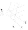
- FIG. 3 is a schematic diagram illustrating the detailed structure of a Mangin mirror of the wide-angle projection optical system according to an embodiment of the present invention.
- the Mangin mirror 221 of the second optical system 22 of the wide-angle projection optical system 2 has positive power
- the Mangin mirror is preferably a refracting and reflecting mirror and not limited to a meniscus lens coated with an anti-reflecting coating (ARC).
- ARC anti-reflecting coating
- the light I projected or emitted through the object side A, the first lens group 211, the aperture stop 212 and the second lens group 213 is transmitted through the refracting surface 2211 of the Mangin mirror 221 from the air, reflected by the reflecting surface 2212, and further transmitted through the refracting surface 2211 in a reverse direction, so the two refractions and the one reflection are implemented.
- the optical path of the two refractions and the one reflection of the light I it can be considered as transmitting through three mediums.
- the design factor and design parameter are added in the present invention, so that the optical system can be easily designed and adjusted for reducing the image distortion and the image aberration.
- the anamorphic polynomial free-form surfaces are not necessary in design of the wide-angle projection optical system 2 of the present disclosure. That is, none of any non-axially symmetric optical component is used in the present invention, so that the manufacturing difficulty is reduced, and tight tolerances are avoided.
- Table 1 shows the prescription data of the lenses.
- No. is a surface number from the object side to the image side.
- R indicates radius of curvature
- T indicates the thickness
- Nd indicates a refractive index
- Vd indicates an Abbe number.
- the front and rear surfaces of the lenses No. 13, No. 14, No. 19, No. 20, No. 21, and No. 22 are all aspheric.
- the aspheric coefficients (k, A4, A6, A8, A10 and A12) of these surfaces are listed in Table 2.
- wide-angle projection optical system 2 of the present invention can achieve a full field angle larger than ⁇ 70 degrees.
- the micro-display is illuminated by a non-telecentric illumination system.
- FIG. 4 is a schematic diagram illustrating modulation transfer function (MTF) characteristics in the image side by the wide-angle projection optical system according to the embodiment of the present invention with the values shown in Table 1.
- the horizontal axis indicates spatial frequency (cycles/mm) and the vertical axis of ordinates indicates modulation values.
- the spatial frequency indicates the number of sine waves per millimeter.
- the maximum value 1 in the vertical axis indicates that the MTF is 100%.
- the MTF is still greater than 50%, which means the MTF ratio does not obviously decrease, so that every pixel is clearly resolved in achieving high quality image.
- FIG. 4 in the Nyquist Frequency, the MTF is still greater than 50%, which means the MTF ratio does not obviously decrease, so that every pixel is clearly resolved in achieving high quality image.
- FIG. 4 in the Nyquist Frequency
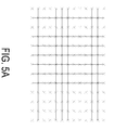
- FIG. 5A is a schematic diagram illustrating grid distortion in the image side by the wide-angle projection optical system according to the embodiment of the present invention with the values shown in Table 1.
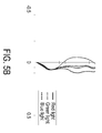
- FIG. 5B is a schematic diagram illustrating distortion curve in the image side by the wide-angle projection optical system according to the embodiment of the present invention with the values shown in Table 1.
- the grid distortion or image distortion can be effectively corrected in the projection areas of the embodiment.
- FIG. 6 is a schematic diagram illustrating lateral color in the image side by the wide-angle projection optical system according to the embodiment of the present invention with the values shown in Table 1. As shown in FIG.
- the wide-angle projection optical system 2 of the present invention has a large full field angle, low image aberration or distortion, good optical characteristics and high image quality.
- a projection with high image quality and low image distortion is implemented by the embodiments mentioned above without any non-axially symmetric optical component.
- FIG. 7 is a schematic diagram illustrating the configuration of a wide-angle projection optical system according to another embodiment of the present invention.
- an object surface 3 is configured as an object side A for the image projected by the wide-angle projection optical system 4 of the present invention to be formed on.
- the wide-angle projection optical system 4 includes, sequentially arranged from the object side A to an image side B, a first optical system 41 and a second optical system 42, and the first optical system 41 and the second optical system 42 are configured to form the wide-angle projection optical system 4 as a telecentric wide-angle projection optical system.
- the first optical system 41 includes a first lens group 411 having positive power and including an aperture stop 412 and a second lens group 413 having positive power
- the second optical system 42 includes a refracting and reflecting mirror 421 including a refracting surface 4211 and a reflecting surface 4212.
- the first lens group 411, the aperture stop 412, the second lens group 413 and the refracting and reflecting mirror 421 are similar with the first lens group 211, the aperture stop 212, the second lens group 213 and the Mangin mirror 221 of the above-mentioned embodiment, and not redundantly described herein.
- the wide-angle projection optical system of the present invention can be a non-telecentric wide-angle projection optical system or a telecentric wide-angle projection optical system for being utilized in digital light processing (DLP) device or liquid crystal displaying (LCD) device.
- DLP digital light processing
- LCD liquid crystal displaying
- Table 3 shows the prescription data of the lenses according to this embodiment.
- "No.” is a surface number from the object side to the image side.
- "R” indicates radius of curvature
- "T” indicates the thickness
- "Nd” indicates a refractive index
- "Vd” indicates an Abbe number.
- the front and rear surfaces of the lenses No. 18, No. 19, No. 24, No. 25, No. 26, NO. 27 and No. 28 are all aspheric.
- the aspheric coefficients (k, A4, A6, A8, A10 and A12) of these surfaces are listed in Table 4.
- wide-angle projection optical system 2 of the present invention can achieve a full field angle larger than ⁇ 70 degrees.
- the micro-display is illuminated by a telecentric illumination system.
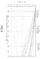
- FIG. 8 is a schematic diagram illustrating modulation transfer function (MTF) characteristics in the image side by the wide-angle projection optical system according to the embodiment of the present invention with the values shown in Table 3.
- the horizontal axis indicates spatial frequency (cycles/mm) and the vertical axis of ordinates indicates modulation values.
- the spatial frequency indicates the number of sine waves per millimeter.
- the maximum value 1 in the vertical axis indicates that the MTF is 100%.
- the MTF is still greater than 50%, which means the MTF ratio does not obviously decrease, so that every pixel is clearly resolved in achieving high quality image.
- FIG. 4 in the Nyquist Frequency, the MTF is still greater than 50%, which means the MTF ratio does not obviously decrease, so that every pixel is clearly resolved in achieving high quality image.
- FIG. 4 in the Nyquist Frequency
- FIG. 9A is a schematic diagram illustrating grid distortion in the image side by the wide-angle projection optical system according to the embodiment of the present invention with the values shown in Table 3.
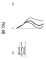
- FIG. 9B is a schematic diagram illustrating distortion curve in the image side by the wide-angle projection optical system according to the embodiment of the present invention with the values shown in Table 3.
- the grid distortion or image distortion can be effectively corrected in the projection areas of the embodiment.
- FIG 10 is a schematic diagram illustrating lateral color in the image side by the wide-angle projection optical system according to the embodiment of the present invention with the values shown in Table 3. As shown in FIG.
- the wide-angle projection optical system 2 of the present invention has a large full field angle, low image aberration or distortion, good optical characteristics and high image quality.
- a projection with high image quality and low image distortion is implemented by the embodiments mentioned above without any non-axially symmetric optical component.
- the wide-angle projection optical system with ultra-short-throw of the present invention is capable of providing a large full field angle.
- the wide-angle projection optical system comprises a first lens group with positive power, a second lens group with positive power, and a Mangin mirror having a refracting surface and a reflecting surface.
- the wide-angle projection optical system may provide a full field angle larger than ⁇ 70 degrees, a very short effective focal length, low image distortion and high image quality.
- the use of the wide-angle projection optical system makes the compact and thin display system possible.
- the projection display apparatus may be installed over the white board or the display screen.
Landscapes
- Physics & Mathematics (AREA)
- General Physics & Mathematics (AREA)
- Optics & Photonics (AREA)
- Lenses (AREA)
- Projection Apparatus (AREA)
Abstract
Description
- The present disclosure relates to a projection optical system, and more particularly to an ultra-short-throw or a wide-angle projection optical system.
- A wide-angle projection lens has a large field of view, or a short effective focal length (EFL). In comparison with a conventional projection lens, the projection display apparatus with a wide-angle projection lens is capable of producing a certain sized image at a shorter distance.
- Recently, an integrated system of a projection display apparatus and an interactive white board has become very useful tool in classrooms, lecture rooms or conference rooms in order to provide the interactive functions about education, demonstration or entertainment.
FIG. 1A is a schematic diagram illustrating an integrated system of a projection display apparatus and an interactive white board according to the prior art. As shown inFIG. 1A , theprojection display apparatus 10 is usually mounted upside down over thewhite board 11. The conventional short-throwprojection display apparatus 10 is usually mounted at a distance of about 1 meter away from thewhite board 11. As such, the lecturer with average height becomes an obstacle to the light path of theprojection display apparatus 10 when writing on thewhite board 11. In addition, the eyes of the lecturer have the potential danger of being illuminated by the light from theprojection display apparatus 10. - For solving the above problems, as shown in
FIG. 1B , theprojection display apparatus 10 needs to be mounted in the vicinity of thewhite board 11. Since the projection distance is very short, theprojection display apparatus 10 should have a wide-angle projection lens to provide a large full field angle θ or a very short focal length. In a case that the projection displayapparatus 10 with a wide-angle projection lens is mounted over thewhite board 11, the light flux needs to incident on thewhite board 11 at a very steep angle, which incurs a large distortion in the image. Moreover, the projection lens also needs to have a large offset to avoid the light hitting on the main body of the projection display apparatus, and avoid the body of reflecting mirror blocking the top area of the white board. In other words, the wide-angle or ultra-short projection lens is very critical for designing the projection display apparatus. -
US patent No. 7,529,032 disclosed a wide-angle projection optical system. Please refer toFIG. 1C , which is a schematic diagram illustrating the configuration of a wide-angle projection optical system according to the prior art. As shown inFIG. 1C , the design uses two aspheric plastic lenses, one double concave negative lens and a negative aspheric reflecting mirror. The total length of the system is quite long. This makes it difficult to have a thin projector system. In addition, the maximum field angle is on the order of 55 degree, which still requires a fairly long projection distance to produce an image that is large enough for practical applications. -
FIG. 1D is a schematic diagram illustrating the configuration of another wide-angle projection optical system according to the prior art.US patent No. 7,048,388 disclosed a wide-angle projection lens design as shown inFIG. 1D that incorporates a flat mirror and a positive aspheric reflecting mirror. However, the optical components of the wide-angle projection optical system have to be tilted and decentered in arrangement for obtaining an undistorted image with better image quality. Otherwise, optical components having anamorphic polynomial free-form surfaces with different magnifications in vertical direction and horizontal direction are necessary to be used in the wide-angle projection optical system, and the complication of assembling or manufacturing optical components are increased. - There is a need of providing a wide-angle projection optical system to obviate the drawbacks encountered from the prior art.
- It is an aspect of the present invention to provide a wide-angle projection optical system with short-throw in order to eliminate the drawbacks of dangers of a conventional optical system, distortions and aberrations.
- An another aspect of the present invention provides a wide-angle projection optical system with ultra-short-throw having a large full field angle, which is for example larger than 70 degrees, a short effective focal length, thin profile, low distortion and aberration and high image quality.
- In accordance with an aspect of the present disclosure, there is provided a wide-angle projection optical system. The wide-angle projection optical system includes, between an object side and an image side, a first optical system including a first lens group having an aperture stop therein and a second lens group, and a second optical system including a Mangin mirror. The first lens group has positive power, and the second lens group has positive power. The first lens group provides optical characteristics to match with a light coming from the object side and converges the light toward the aperture stop. The second lens group is disposed behind the aperture stop. The first lens group and the second lens group are configured to form an aberrated real image in front of the Mangin mirror. The Mangin mirror is disposed closer to the image side than the first lens group, the aperture stop and the second lens group. The Mangin mirror includes a refracting surface and a reflecting surface for refracting the light two times and reflecting the light one time, thereby producing an enlarged real image on a screen.
- In accordance with another aspect of the present disclosure, there is provided a wide-angle projection optical system. The wide-angle projection optical system includes, from an object side to an image side, a first optical system including a first lens group having an aperture stop therein and a second lens group, and a second optical system including a refracting and reflecting mirror with positive power. The first lens group has positive power, and the second lens group has positive power. The first lens group provides optical characteristics to match with a light coming from the object side and converges the light toward the aperture stop. The second lens group is disposed behind the aperture stop, and both surfaces of at least one lens of the second lens group are aspheric. The first lens group and the second lens group are configured to form an aberrated real image in front of the refracting and reflecting mirror with positive power. The refracting and reflecting mirror includes a refracting surface and a reflecting surface for refracting the light two times and reflecting the light one time, thereby producing an enlarged real image on a screen. The first lens group, the second lens group and the refracting and reflecting mirror have a common optical axis.
- The above contents of the present disclosure will become more readily apparent to those ordinarily skilled in the art after reviewing the following detailed description and accompanying drawings, in which:
-
-
FIG. 1A is a schematic diagram illustrating an integrated system of a projection display apparatus and an interactive white board according to the prior art; -
FIG. 1B is a schematic diagram illustrating an integrated system of a wide-angle projection display apparatus and an interactive white board according to the prior art; -
FIG. 1C is a schematic diagram illustrating the configuration of a wide-angle projection optical system according to the prior art; -
FIG. 1D is a schematic diagram illustrating the configuration of another wide-angle projection optical system according to the prior art; -
FIG. 2 is a schematic diagram illustrating the configuration of a wide-angle projection optical system according to an embodiment of the present invention; -
FIG. 3 is a schematic diagram illustrating the detailed structure of a Mangin mirror of the wide-angle projection optical system according to an embodiment of the present invention; -
FIG. 4 is a schematic diagram illustrating modulation transfer function (MTF) characteristics in the image side by the wide-angle projection optical system according to the embodiment of the present invention with the values shown in Table 1; -
FIG. 5A is a schematic diagram illustrating grid distortion in the image side by the wide-angle projection optical system according to the embodiment of the present invention with the values shown in Table 1; -
FIG. 5B is a schematic diagram illustrating distortion curve in the image side by the wide-angle projection optical system according to the embodiment of the present invention with the values shown in Table 1; -
FIG. 6 is a schematic diagram illustrating lateral color in the image side by the wide-angle projection optical system according to the embodiment of the present invention with the values shown in Table 1; -
FIG. 7 is a schematic diagram illustrating the configuration of a wide-angle projection optical system according to another embodiment of the present invention; -
FIG. 8 is a schematic diagram illustrating modulation transfer function (MTF) characteristics in the image side by the wide-angle projection optical system according to the embodiment of the present invention with the values shown in Table 3; -
FIG. 9A is a schematic diagram illustrating grid distortion in the image side by the wide-angle projection optical system according to the embodiment of the present invention with the values shown in Table 3; -
FIG. 9B is a schematic diagram illustrating distortion curve in the image side by the wide-angle projection optical system according to the embodiment of the present invention with the values shown in Table 3; and -
FIG. 10 is a schematic diagram illustrating lateral color in the image side by the wide-angle projection optical system according to the embodiment of the present invention with the values shown in Table 3. - The present disclosure will now be described more specifically with reference to the following embodiments. It is to be noted that the following descriptions of preferred embodiments of this disclosure are presented herein for purpose of illustration and description only. It is not intended to be exhaustive or to be limited to the precise form disclosed.
- Please refer to
FIG. 2. FIG. 2 is a schematic diagram illustrating the configuration of a wide-angle projection optical system according to an embodiment of the present invention. As shown inFIG. 2 , the wide-angle projectionoptical system 2 is a non-telecentric projection optical system, which can be applied to a projection display apparatus. The projection display apparatus includes, but not limited to, a digital micromirror device (hereinafter "DMD"). The DMD has anobject surface 3, which is an image-displaying surface of a light valve. Theobject surface 3 is configured as an object side A for the image projected by the wide-angle projectionoptical system 2 of the present invention to be formed on. In this embodiment, the wide-angle projectionoptical system 2 includes, between the object side A and an image side B, a firstoptical system 21 and a secondoptical system 22, among which the firstoptical system 21 and the secondoptical system 22 are configured to form the wide-angle projectionoptical system 2 as a non-telecentric wide-angle projection optical system. The firstoptical system 21 includes afirst lens group 211 having positive power and including anaperture stop 212 and asecond lens group 213 having positive power, and the secondoptical system 22 includes aMangin mirror 221. Thefirst lens group 211 sets up proper working space and pupil position to match with the illumination optical system. In other words, thefirst lens group 211 is configured to provide optical characteristics to match with a light coming from the object side A and converge the light toward theaperture stop 212, such that the light is further projected or outputted to thesecond lens group 213. - In particular, the
first lens group 211 of the wide-angle projectionoptical system 2 consists of a plurality of refraction lenses and has positive effective optical power for providing the telecentricity of object space and converging the light emitted toward theaperture stop 212 by the DMD. In this embodiment, theaperture stop 212 is located in thefirst lens group 211 and at the focus point of the main light. Moreover, theMangin mirror 221 is disposed closer to the image side B than thefirst lens group 211, theaperture stop 212 and thesecond lens group 213. An aberrated real image is formed by thefirst lens group 211 and thesecond lens group 213. TheMangin mirror 221 includes a refractingsurface 2211 and a reflectingsurface 2212 for refracting the light two times and reflecting the light one time, thereby producing an enlarged real image on a screen in order to correct aberration and distortion. Therefore, the full field angle is enhanced, and the projection lens or the body of the projection display apparatus can be located between the reflecting mirror and the screen, thereby miniaturizing the integrated projection system. - The
first lens group 211, theaperture stop 212 and thesecond lens group 213 of the firstoptical system 21 and theMangin mirror 221 of the secondoptical system 22 of the wide-angle projectionoptical system 2 of one embodiment of the present invention are arranged sequentially from the object side A to the image side B, but are not limited thereto. Every lens of thefirst lens group 211 and thesecond lens group 213 and theMangin mirror 221 have a common optical axis. In addition, the exteriors of each lens of thefirst lens group 211 and each lens of thesecond lens group 213 of the firstoptical system 21 and theMangin mirror 221 of the secondoptical system 22 are axially symmetric relative to the common optical axis. - In this embodiment, the surfaces of each lens of the
first lens group 211 are spherical, but aspheric surfaces also can be used to further reduce the aberration and distortion of the final image in other embodiments. That is, both surfaces of each lens of the first lens group 211 (e.g. the front surface and the rear surface) are either spherical or aspheric. Furthermore, at least one lens of thesecond lens group 213 is an aspheric lens. Both surfaces, namely the front surface and the rear surface, of at least one lens of thesecond lens group 213 are aspheric in order to correct aberration and distortion. In each embodiment of the present invention, the effective optical power is properly distributed among the lenses of thefirst lens group 211 and/or thesecond lens group 213 in order to lower the sensitivity to mechanical tolerances. - Please refer to
FIG. 2 andFIG. 3. FIG. 3 is a schematic diagram illustrating the detailed structure of a Mangin mirror of the wide-angle projection optical system according to an embodiment of the present invention. As shown inFIG. 2 andFIG. 3 , theMangin mirror 221 of the secondoptical system 22 of the wide-angle projectionoptical system 2 has positive power, and the Mangin mirror is preferably a refracting and reflecting mirror and not limited to a meniscus lens coated with an anti-reflecting coating (ARC). In some preferable embodiments, the light I projected or emitted through the object side A, thefirst lens group 211, theaperture stop 212 and thesecond lens group 213 is transmitted through the refractingsurface 2211 of theMangin mirror 221 from the air, reflected by the reflectingsurface 2212, and further transmitted through the refractingsurface 2211 in a reverse direction, so the two refractions and the one reflection are implemented. In brief, regarding the optical path of the two refractions and the one reflection of the light I, it can be considered as transmitting through three mediums. Compared with the conventional reflecting mirror applied in the prior art, the design factor and design parameter are added in the present invention, so that the optical system can be easily designed and adjusted for reducing the image distortion and the image aberration. Moreover, by utilizing the refractingsurface 2211 and the reflectingsurface 2212 of theMangin mirror 221, the anamorphic polynomial free-form surfaces are not necessary in design of the wide-angle projectionoptical system 2 of the present disclosure. That is, none of any non-axially symmetric optical component is used in the present invention, so that the manufacturing difficulty is reduced, and tight tolerances are avoided. - Table 1 shows the prescription data of the lenses. In Table 1, "No." is a surface number from the object side to the image side. "R" indicates radius of curvature, "T" indicates the thickness, "Nd" indicates a refractive index, and "Vd" indicates an Abbe number. The front and rear surfaces of the lenses No. 13, No. 14, No. 19, No. 20, No. 21, and No. 22 are all aspheric. The aspheric coefficients (k, A4, A6, A8, A10 and A12) of these surfaces are listed in Table 2. As a consequence, wide-angle projection
optical system 2 of the present invention can achieve a full field angle larger than ±70 degrees. In this embodiment the micro-display is illuminated by a non-telecentric illumination system. This means that the central rays from each filed on the micro-display are essentially concentrated toward a point at a finite distance from the micro-display.Table 1 No. R T Nd Vd 0 Infinity 0.7 1 Infinity 1.050 1.51 63.0 2 Infinity 19.936 3 -1421.486 2.614 1.50 81.5 4 -29.764 0.15 5 410.168 2.306 1.60 65.4 6 -47.968 2.954 7 -20.458 1.000 1.67 33.0 8 21.148 3.286 1.5 81.5 9 -29.890 0.960 10 Infinity 0.361 11 42.326 2.935 1.67 48.3 12 -31.694 23.320 13 72.172 6.589 1.53 56.0 14 -1692.620 1.439 15 56.672 5.066 1.65 39.7 16 -138.685 3.492 17 -33.126 6.706 1.60 65.4 18 196.555 1.561 19 -89.079 4.505 1.53 56 20 32.955 103.683 21 -86.710 6.923 1.53 56 22 -62.982 -6.923 -1 0 23 -86.710 -613.116 24 Infinity Table 2 No. k A4 A6 A8 A10 A12 13 -8.826 -1.334e-5 -2.443e-8 -5.594e-11 -3.515e-13 3.856e-16 14 3.09e+05 4.526e-6 2.188e-8 -7.790e-11 1.208e-14 1.016e-15 19 -50.607 8.271e-6 9.983e-9 3.272e-11 -6.168e-13 1.723e-17 20 -4.391 -3.152e-6 2.616e-9 2.269e-12 8.648e-15 5.275e-18 21 -1.877 -8.721e-7 2.383e-11 9.764e-15 -1.020e-18 2.334e-23 22 -2.965 -8.610e-7 5.423e-11 -5.071e-16 -3.133e-19 5.454e-24 23 -1.877 -8.721e-7 2.383e-11 9.764e-15 -1.020e-18 2.334e-23 -
FIG. 4 is a schematic diagram illustrating modulation transfer function (MTF) characteristics in the image side by the wide-angle projection optical system according to the embodiment of the present invention with the values shown in Table 1. The horizontal axis indicates spatial frequency (cycles/mm) and the vertical axis of ordinates indicates modulation values. The spatial frequency indicates the number of sine waves per millimeter. The maximum value 1 in the vertical axis indicates that the MTF is 100%. As shown inFIG. 4 , in the Nyquist Frequency, the MTF is still greater than 50%, which means the MTF ratio does not obviously decrease, so that every pixel is clearly resolved in achieving high quality image.FIG. 5A is a schematic diagram illustrating grid distortion in the image side by the wide-angle projection optical system according to the embodiment of the present invention with the values shown in Table 1.FIG. 5B is a schematic diagram illustrating distortion curve in the image side by the wide-angle projection optical system according to the embodiment of the present invention with the values shown in Table 1. As shown inFIG. 5A andFIG. 5B , the grid distortion or image distortion can be effectively corrected in the projection areas of the embodiment.FIG. 6 is a schematic diagram illustrating lateral color in the image side by the wide-angle projection optical system according to the embodiment of the present invention with the values shown in Table 1. As shown inFIG. 6 , the difference of the lateral colors is less than a pixel, so that the color dislocation issue is avoided when projecting color lights, which means the chromatic aberration is also effectively corrected by the present invention. From the above drawings, the wide-angle projectionoptical system 2 of the present invention has a large full field angle, low image aberration or distortion, good optical characteristics and high image quality. A projection with high image quality and low image distortion is implemented by the embodiments mentioned above without any non-axially symmetric optical component. - Please refer to
FIG. 7. FIG. 7 is a schematic diagram illustrating the configuration of a wide-angle projection optical system according to another embodiment of the present invention. As shown inFIG. 7 , anobject surface 3 is configured as an object side A for the image projected by the wide-angle projectionoptical system 4 of the present invention to be formed on. In this embodiment, the wide-angle projectionoptical system 4 includes, sequentially arranged from the object side A to an image side B, a firstoptical system 41 and a secondoptical system 42, and the firstoptical system 41 and the secondoptical system 42 are configured to form the wide-angle projectionoptical system 4 as a telecentric wide-angle projection optical system. The firstoptical system 41 includes afirst lens group 411 having positive power and including anaperture stop 412 and asecond lens group 413 having positive power, and the secondoptical system 42 includes a refracting and reflectingmirror 421 including a refractingsurface 4211 and a reflectingsurface 4212. Thefirst lens group 411, theaperture stop 412, thesecond lens group 413 and the refracting and reflectingmirror 421 are similar with thefirst lens group 211, theaperture stop 212, thesecond lens group 213 and theMangin mirror 221 of the above-mentioned embodiment, and not redundantly described herein. It should be noted that the wide-angle projection optical system of the present invention can be a non-telecentric wide-angle projection optical system or a telecentric wide-angle projection optical system for being utilized in digital light processing (DLP) device or liquid crystal displaying (LCD) device. - Table 3 shows the prescription data of the lenses according to this embodiment. In Table 3, "No." is a surface number from the object side to the image side. "R" indicates radius of curvature, "T" indicates the thickness, "Nd" indicates a refractive index, and "Vd" indicates an Abbe number. The front and rear surfaces of the lenses No. 18, No. 19, No. 24, No. 25, No. 26, NO. 27 and No. 28 are all aspheric. The aspheric coefficients (k, A4, A6, A8, A10 and A12) of these surfaces are listed in Table 4. As a consequence, wide-angle projection
optical system 2 of the present invention can achieve a full field angle larger than ±70 degrees. In this embodiment the micro-display is illuminated by a telecentric illumination system. This means that the central rays from each filed on the micro-display are essentially collimated from the micro-display.Table 3 No. R T Nd Vd 0 Infinity 0.7 1 Infinity 1.050 1.51 63.0 2 Infinity 1 3 Infinity 18 1.52 64.1 4 Infinity 5 5 48.9351 5.448 1.50 81.5 6 -69.6432 0.128 7 350.5973 3.62 1.49 70.2 8 -60.8138 0.15 9 53.6141 4.219 1.50 81.5 10 -91.3327 1.86 11 85.8327 11.213 1.75 35.3 12 75.3116 3.026 13 -20.8099 2.834 1.69 31.1 14 18.2072 4.347 1.50 81.5 15 -33.3142 1.848 16 36.1211 11.073 1.60 39.2 17 -37.1867 20.315 18 49.3392 5.21 1.53 56.0 19 -5321.1473 0.196 20 69.0805 5.819 1.76 27.5 21 -337.8203 3.626 22 -32.3685 11 1.62 60.3 23 743.4352 1.637 24 -43.9674 5.485 1.53 56.0 25 34.7057 102.68 26 -82.1935 6.244 1.53 56.0 27 -62.4958 -6.244 -1 0 28 -82.1935 -625.847 29 Infinity Table 4 No. k A4 A6 A8 A10 A12 18 0.0352 -7.1386e-6 -8.1380e-9 -5.3639e-11 -3.4127e-13 -5.6496e-16 19 -932.1597 1.2229e-6 5.0426e-9 -7.9514e-11 -3.0201e-13 2.9009e-16 24 -11.1474 1.0568e-5 1.6169e-8 3.9028e-11 -8.8211e-14 1.9858e-17 25 -4.7449 -2.0330e-6 6.3947e-9 5.6832e-12 4.6915e-15 1.0894e-17 26 -1.9369 -8.7074e-7 2.3081e-11 9.7287e-15 1.0514e-18 2.0919e-23 27 -2.8101 -8.5863e-7 5.3320e-11 -7.9959e-16 -3.2209e-19 5.7242e-24 28 -1.9369 -8.5863e-7 5.3320e-11 -7.9959e-16 -3.2209e-19 5.7242e-24 -
FIG. 8 is a schematic diagram illustrating modulation transfer function (MTF) characteristics in the image side by the wide-angle projection optical system according to the embodiment of the present invention with the values shown in Table 3. The horizontal axis indicates spatial frequency (cycles/mm) and the vertical axis of ordinates indicates modulation values. The spatial frequency indicates the number of sine waves per millimeter. The maximum value 1 in the vertical axis indicates that the MTF is 100%. As shown inFIG. 4 , in the Nyquist Frequency, the MTF is still greater than 50%, which means the MTF ratio does not obviously decrease, so that every pixel is clearly resolved in achieving high quality image.FIG. 9A is a schematic diagram illustrating grid distortion in the image side by the wide-angle projection optical system according to the embodiment of the present invention with the values shown in Table 3.FIG. 9B is a schematic diagram illustrating distortion curve in the image side by the wide-angle projection optical system according to the embodiment of the present invention with the values shown in Table 3. As shown inFIG. 5A andFIG. 5B , the grid distortion or image distortion can be effectively corrected in the projection areas of the embodiment.FIG 10 is a schematic diagram illustrating lateral color in the image side by the wide-angle projection optical system according to the embodiment of the present invention with the values shown in Table 3. As shown inFIG. 6 , the difference of the lateral colors is less than a pixel, so that the color dislocation issue is avoided when projecting color lights, which means the chromatic aberration is also effectively corrected by the present invention. From the above drawings, the wide-angle projectionoptical system 2 of the present invention has a large full field angle, low image aberration or distortion, good optical characteristics and high image quality. A projection with high image quality and low image distortion is implemented by the embodiments mentioned above without any non-axially symmetric optical component. - From the above description, the wide-angle projection optical system with ultra-short-throw of the present invention is capable of providing a large full field angle. The wide-angle projection optical system comprises a first lens group with positive power, a second lens group with positive power, and a Mangin mirror having a refracting surface and a reflecting surface. The wide-angle projection optical system may provide a full field angle larger than ±70 degrees, a very short effective focal length, low image distortion and high image quality. The use of the wide-angle projection optical system makes the compact and thin display system possible. Moreover, by means of the wide-angle projection optical system, the projection display apparatus may be installed over the white board or the display screen.
Claims (11)
- A wide-angle projection optical system (2), between an object side (A) and an image side (B), the wide-angle projection optical system (2) comprising:a first optical system (21) comprising:a first lens group (211) having positive power and comprising an aperture stop (212) for providing optical characteristics to match with a light coming from the object side (A) and converging the light toward the aperture stop (212); anda second lens group (213) having positive power, wherein the second lens group (213) is disposed behind the aperture stop (212); anda second optical system (22) comprising:a Mangin mirror (221) disposed closer to the image side (B) than the first lens group (211), the aperture stop (212) and the second lens group (213), wherein the first lens group (211) and the second lens group (213) are configured to form an aberrated real image in front of the Mangin mirror (221), and wherein the Mangin mirror (221) includes a refracting surface (2211) and a reflecting surface (2212) for refracting the light two times and reflecting the light one time, thereby producing an enlarged real image on a screen.
- The wide-angle projection optical system according to claim 1, wherein the first lens group (211), the second lens group (213) and the Mangin mirror (221) are arranged sequentially from the object side (A) to the image side (B).
- The wide-angle projection optical system according to claim 1 or 2, wherein the Mangin mirror (221) has positive power.
- The wide-angle projection optical system according to any of the claims 1 to 3, wherein the first lens group (211), the second lens group (213) and the Mangin mirror (221) have a common optical axis.
- The wide-angle projection optical system according to any of the claims 1 to 4, wherein the light is transmitted through the refracting surface (2211) of the Mangin mirror (221), reflected by the reflecting surface (2212), and further transmitted through the refracting surface (2211) in a reverse direction.
- The wide-angle projection optical system according to any of the claims 1 to 5, wherein each lens of the first lens group (211) is axially symmetric and is either a spherical lens or an aspheric lens.
- The wide-angle projection optical system according to any of the claims 1 to 6, wherein both surfaces of at least one lens of the second lens group (213) are aspheric.
- The wide-angle projection optical system according to claim 7, wherein each lens of the second lens group (213) is axially symmetric.
- The wide-angle projection optical system according to any of the claims 1 to 8, wherein the first optical system (21) and the second optical system (22) are configured to form the wide-angle projection optical system (2) as a telecentric wide-angle projection optical system.
- the wide-angle projection optical system according to any oft he claims 1 to 9, wherein the first optical system (21) and the second optical system (22) are configured to form the wide-angle projection optical system (2) as a non-telecentric wide-angle projection optical system.
- A wide-angle projection optical system (4), from an object side (A) to an image side (B), the wide-angle projection optical system (4) comprising:a first optical system (41) comprising:a first lens group (411) having positive power and comprising an aperture stop (412) for providing optical characteristics to match with a light coming from the object side (A) and converging the light toward the aperture stop (412); anda second lens group (413) having positive power, wherein the second lens group (413) is disposed behind the aperture stop (412), and both surfaces of at least one lens of the second lens group (413) are aspheric; anda second optical system (42) comprising:a refracting and reflecting mirror (421) with positive power, wherein the first lens group (411) and the second lens group (413) are configured to form an aberrated real image in front of the refracting and reflecting mirror (421) with positive power, and wherein the refracting and reflecting mirror (421) includes a refracting surface (4211) and a reflecting surface (4212) for refracting the light two times and reflecting the light one time, thereby producing an enlarged real image on a screen;wherein the first lens group (411), the second lens group (413) and the refracting and reflecting mirror (421) have a common optical axis.
Applications Claiming Priority (1)
| Application Number | Priority Date | Filing Date | Title |
|---|---|---|---|
| TW102144713A TWI497114B (en) | 2013-12-05 | 2013-12-05 | Wide-angle projection optical system |
Publications (1)
| Publication Number | Publication Date |
|---|---|
| EP2881776A1 true EP2881776A1 (en) | 2015-06-10 |
Family
ID=50070353
Family Applications (1)
| Application Number | Title | Priority Date | Filing Date |
|---|---|---|---|
| EP14153879.3A Withdrawn EP2881776A1 (en) | 2013-12-05 | 2014-02-04 | Wide-angle projection optical system |
Country Status (4)
| Country | Link |
|---|---|
| US (1) | US20150160441A1 (en) |
| EP (1) | EP2881776A1 (en) |
| JP (1) | JP2015108797A (en) |
| TW (1) | TWI497114B (en) |
Cited By (3)
| Publication number | Priority date | Publication date | Assignee | Title |
|---|---|---|---|---|
| CN110045483A (en) * | 2018-01-16 | 2019-07-23 | 佳能株式会社 | Imaging optical system, image projection device and camera arrangement |
| CN110780514A (en) * | 2018-07-27 | 2020-02-11 | 精工爱普生株式会社 | Lens and projection type image display device |
| CN112764208A (en) * | 2021-01-13 | 2021-05-07 | 中山联合光电科技股份有限公司 | Optical system and projection equipment |
Families Citing this family (11)
| Publication number | Priority date | Publication date | Assignee | Title |
|---|---|---|---|---|
| US10107996B2 (en) * | 2013-12-05 | 2018-10-23 | Delta Electronics, Inc. | Wide-angle projection optical system |
| KR20150141820A (en) * | 2014-06-10 | 2015-12-21 | 삼성전자주식회사 | Objective lens assembly having catadioptric group |
| JP6417564B2 (en) * | 2014-07-02 | 2018-11-07 | 株式会社コシナ | Reflective projection device |
| JP6993251B2 (en) | 2018-02-01 | 2022-01-13 | リコーインダストリアルソリューションズ株式会社 | Projection optical system and image display device |
| JP7124521B2 (en) * | 2018-07-30 | 2022-08-24 | セイコーエプソン株式会社 | Projection optical system and projection image display device |
| JP7148334B2 (en) * | 2018-09-07 | 2022-10-05 | リコーインダストリアルソリューションズ株式会社 | Projection optical system and image projection device |
| JP7088217B2 (en) * | 2020-01-20 | 2022-06-21 | セイコーエプソン株式会社 | Projection optics and projector |
| JP2021117279A (en) * | 2020-01-23 | 2021-08-10 | セイコーエプソン株式会社 | Projection optics and projector |
| JP7424072B2 (en) * | 2020-01-24 | 2024-01-30 | セイコーエプソン株式会社 | Projection optical system and projector |
| TWI782327B (en) * | 2020-09-18 | 2022-11-01 | 上暘光學股份有限公司 | Projection Optical System |
| CN114253054B (en) * | 2020-09-22 | 2025-02-07 | 上旸光学股份有限公司 | Projection optical system |
Citations (6)
| Publication number | Priority date | Publication date | Assignee | Title |
|---|---|---|---|---|
| US20040212789A1 (en) * | 2003-04-07 | 2004-10-28 | Yong-Dok Cha | Optical illumination system and image projection system including the same |
| JP2005292813A (en) * | 2004-03-12 | 2005-10-20 | Sony Corp | Projection optical system and image projection apparatus |
| US7048388B2 (en) | 2003-02-06 | 2006-05-23 | Ricoh Company, Ltd. | Projection optical system, magnification projection optical system, magnification projection apparatus, and image projection apparatus |
| JP2006133312A (en) * | 2004-11-02 | 2006-05-25 | Ricoh Co Ltd | Mangin mirror and projector having the mangin mirror |
| US7529032B2 (en) | 2006-05-01 | 2009-05-05 | Ricoh Company, Ltd. | Projection optical system and image display apparatus |
| US20110026111A1 (en) * | 2009-07-30 | 2011-02-03 | Yukiko Nagatoshi | Projection optical system and projection display device using the same |
Family Cites Families (9)
| Publication number | Priority date | Publication date | Assignee | Title |
|---|---|---|---|---|
| US20080151365A1 (en) * | 2004-01-14 | 2008-06-26 | Carl Zeiss Smt Ag | Catadioptric projection objective |
| US7116498B2 (en) * | 2004-03-12 | 2006-10-03 | Sony Corporation | Projection optical system and image projection apparatus |
| JP4873927B2 (en) * | 2005-11-01 | 2012-02-08 | オリンパス株式会社 | Optical system |
| US7883219B2 (en) * | 2006-12-27 | 2011-02-08 | Texas Instruments Incorporated | System and method for displaying images |
| FR2955673B1 (en) * | 2010-01-22 | 2012-07-27 | Optinvent | REASONABLY WIDE ANGLE DISTANCE PROJECTION DEVICE WITH ZOOM AND FOCUS |
| TWI418845B (en) * | 2010-06-01 | 2013-12-11 | Young Optics Inc | Fixed-focus lens |
| JP5728202B2 (en) * | 2010-11-16 | 2015-06-03 | 株式会社サムスン日本研究所 | Projection optical system and image projection apparatus |
| HK1204367A1 (en) * | 2012-01-09 | 2015-11-13 | 眼见360股份有限公司 | Panoramic optical systems |
| JP5767614B2 (en) * | 2012-09-04 | 2015-08-19 | 日東光学株式会社 | Projection optical system and projector apparatus |
-
2013
- 2013-12-05 TW TW102144713A patent/TWI497114B/en active
-
2014
- 2014-01-29 US US14/167,782 patent/US20150160441A1/en not_active Abandoned
- 2014-02-04 EP EP14153879.3A patent/EP2881776A1/en not_active Withdrawn
- 2014-04-11 JP JP2014081758A patent/JP2015108797A/en active Pending
Patent Citations (6)
| Publication number | Priority date | Publication date | Assignee | Title |
|---|---|---|---|---|
| US7048388B2 (en) | 2003-02-06 | 2006-05-23 | Ricoh Company, Ltd. | Projection optical system, magnification projection optical system, magnification projection apparatus, and image projection apparatus |
| US20040212789A1 (en) * | 2003-04-07 | 2004-10-28 | Yong-Dok Cha | Optical illumination system and image projection system including the same |
| JP2005292813A (en) * | 2004-03-12 | 2005-10-20 | Sony Corp | Projection optical system and image projection apparatus |
| JP2006133312A (en) * | 2004-11-02 | 2006-05-25 | Ricoh Co Ltd | Mangin mirror and projector having the mangin mirror |
| US7529032B2 (en) | 2006-05-01 | 2009-05-05 | Ricoh Company, Ltd. | Projection optical system and image display apparatus |
| US20110026111A1 (en) * | 2009-07-30 | 2011-02-03 | Yukiko Nagatoshi | Projection optical system and projection display device using the same |
Cited By (5)
| Publication number | Priority date | Publication date | Assignee | Title |
|---|---|---|---|---|
| CN110045483A (en) * | 2018-01-16 | 2019-07-23 | 佳能株式会社 | Imaging optical system, image projection device and camera arrangement |
| CN110780514A (en) * | 2018-07-27 | 2020-02-11 | 精工爱普生株式会社 | Lens and projection type image display device |
| CN110780514B (en) * | 2018-07-27 | 2021-08-24 | 精工爱普生株式会社 | Lens and projection type image display device |
| CN112764208A (en) * | 2021-01-13 | 2021-05-07 | 中山联合光电科技股份有限公司 | Optical system and projection equipment |
| US12181646B2 (en) | 2021-01-13 | 2024-12-31 | Union Optech Co., Ltd. | Optical system and projection device |
Also Published As
| Publication number | Publication date |
|---|---|
| US20150160441A1 (en) | 2015-06-11 |
| JP2015108797A (en) | 2015-06-11 |
| TWI497114B (en) | 2015-08-21 |
| TW201523026A (en) | 2015-06-16 |
Similar Documents
| Publication | Publication Date | Title |
|---|---|---|
| US20150160441A1 (en) | Wide-angle projection optical system | |
| US8279527B2 (en) | Wide-angle projection optical system | |
| US10107996B2 (en) | Wide-angle projection optical system | |
| US10761415B2 (en) | Projection optical system and projector apparatus | |
| US8675292B2 (en) | Projection lens and projection apparatus | |
| CN105190395B (en) | Projection type image display device | |
| CN105974560B (en) | Wide-angle projection system and lens | |
| JP2011033737A (en) | Projection optical system and projection type display using the same | |
| CN114047613A (en) | Optical system and projection device | |
| CN109874302B (en) | Optical system, image magnifying device, virtual reality glasses and augmented reality glasses | |
| CN104698574A (en) | Wide-angle projection optical system | |
| CN112462491A (en) | Projection lens and projector | |
| JP2020529031A (en) | Reflective wide-angle lens unit | |
| US8967812B2 (en) | Projection optical system and projection display apparatus | |
| CN100417969C (en) | Projection optical system and projection type image display device | |
| US20110085254A1 (en) | Fixed-focus lens | |
| US9625691B2 (en) | Projection lens | |
| CN107817593B (en) | Ultra-short focal projection lens | |
| KR101754604B1 (en) | Projection lens unit of projector | |
| CN214202035U (en) | High-resolution projection lens for projecting large view field | |
| CN112578610B (en) | Projection lens and laser projection equipment | |
| CN105785553A (en) | Miniaturizable short-focus projection lens | |
| CN117492192A (en) | Projection lens | |
| CN101336393A (en) | Wide angle projection lens system and method |
Legal Events
| Date | Code | Title | Description |
|---|---|---|---|
| PUAI | Public reference made under article 153(3) epc to a published international application that has entered the european phase |
Free format text: ORIGINAL CODE: 0009012 |
|
| 17P | Request for examination filed |
Effective date: 20140204 |
|
| AK | Designated contracting states |
Kind code of ref document: A1 Designated state(s): AL AT BE BG CH CY CZ DE DK EE ES FI FR GB GR HR HU IE IS IT LI LT LU LV MC MK MT NL NO PL PT RO RS SE SI SK SM TR |
|
| AX | Request for extension of the european patent |
Extension state: BA ME |
|
| R17P | Request for examination filed (corrected) |
Effective date: 20151119 |
|
| RBV | Designated contracting states (corrected) |
Designated state(s): AL AT BE BG CH CY CZ DE DK EE ES FI FR GB GR HR HU IE IS IT LI LT LU LV MC MK MT NL NO PL PT RO RS SE SI SK SM TR |
|
| STAA | Information on the status of an ep patent application or granted ep patent |
Free format text: STATUS: EXAMINATION IS IN PROGRESS |
|
| 17Q | First examination report despatched |
Effective date: 20170519 |
|
| STAA | Information on the status of an ep patent application or granted ep patent |
Free format text: STATUS: THE APPLICATION IS DEEMED TO BE WITHDRAWN |
|
| 18D | Application deemed to be withdrawn |
Effective date: 20180626 |