EP2881746A1 - Rotation speed detection device - Google Patents
Rotation speed detection device Download PDFInfo
- Publication number
- EP2881746A1 EP2881746A1 EP13825012.1A EP13825012A EP2881746A1 EP 2881746 A1 EP2881746 A1 EP 2881746A1 EP 13825012 A EP13825012 A EP 13825012A EP 2881746 A1 EP2881746 A1 EP 2881746A1
- Authority
- EP
- European Patent Office
- Prior art keywords
- compressor
- blades
- detection unit
- rotation speed
- detection device
- Prior art date
- Legal status (The legal status is an assumption and is not a legal conclusion. Google has not performed a legal analysis and makes no representation as to the accuracy of the status listed.)
- Granted
Links
- 238000001514 detection method Methods 0.000 title claims abstract description 108
- 230000002265 prevention Effects 0.000 abstract description 4
- 230000008878 coupling Effects 0.000 description 18
- 238000010168 coupling process Methods 0.000 description 18
- 238000005859 coupling reaction Methods 0.000 description 18
- 230000006835 compression Effects 0.000 description 13
- 238000007906 compression Methods 0.000 description 13
- 230000003247 decreasing effect Effects 0.000 description 6
- 238000005259 measurement Methods 0.000 description 3
- 230000000694 effects Effects 0.000 description 2
- 238000000034 method Methods 0.000 description 2
- 238000003780 insertion Methods 0.000 description 1
- 230000037431 insertion Effects 0.000 description 1
- 238000009434 installation Methods 0.000 description 1
Images


Classifications
-
- G—PHYSICS
- G01—MEASURING; TESTING
- G01P—MEASURING LINEAR OR ANGULAR SPEED, ACCELERATION, DECELERATION, OR SHOCK; INDICATING PRESENCE, ABSENCE, OR DIRECTION, OF MOVEMENT
- G01P3/00—Measuring linear or angular speed; Measuring differences of linear or angular speeds
- G01P3/42—Devices characterised by the use of electric or magnetic means
- G01P3/44—Devices characterised by the use of electric or magnetic means for measuring angular speed
- G01P3/48—Devices characterised by the use of electric or magnetic means for measuring angular speed by measuring frequency of generated current or voltage
- G01P3/481—Devices characterised by the use of electric or magnetic means for measuring angular speed by measuring frequency of generated current or voltage of pulse signals
-
- G—PHYSICS
- G01—MEASURING; TESTING
- G01P—MEASURING LINEAR OR ANGULAR SPEED, ACCELERATION, DECELERATION, OR SHOCK; INDICATING PRESENCE, ABSENCE, OR DIRECTION, OF MOVEMENT
- G01P3/00—Measuring linear or angular speed; Measuring differences of linear or angular speeds
- G01P3/42—Devices characterised by the use of electric or magnetic means
- G01P3/44—Devices characterised by the use of electric or magnetic means for measuring angular speed
- G01P3/49—Devices characterised by the use of electric or magnetic means for measuring angular speed using eddy currents
-
- F—MECHANICAL ENGINEERING; LIGHTING; HEATING; WEAPONS; BLASTING
- F01—MACHINES OR ENGINES IN GENERAL; ENGINE PLANTS IN GENERAL; STEAM ENGINES
- F01D—NON-POSITIVE DISPLACEMENT MACHINES OR ENGINES, e.g. STEAM TURBINES
- F01D17/00—Regulating or controlling by varying flow
- F01D17/02—Arrangement of sensing elements
- F01D17/06—Arrangement of sensing elements responsive to speed
-
- F—MECHANICAL ENGINEERING; LIGHTING; HEATING; WEAPONS; BLASTING
- F01—MACHINES OR ENGINES IN GENERAL; ENGINE PLANTS IN GENERAL; STEAM ENGINES
- F01D—NON-POSITIVE DISPLACEMENT MACHINES OR ENGINES, e.g. STEAM TURBINES
- F01D21/00—Shutting-down of machines or engines, e.g. in emergency; Regulating, controlling, or safety means not otherwise provided for
- F01D21/02—Shutting-down responsive to overspeed
-
- F—MECHANICAL ENGINEERING; LIGHTING; HEATING; WEAPONS; BLASTING
- F04—POSITIVE - DISPLACEMENT MACHINES FOR LIQUIDS; PUMPS FOR LIQUIDS OR ELASTIC FLUIDS
- F04D—NON-POSITIVE-DISPLACEMENT PUMPS
- F04D27/00—Control, e.g. regulation, of pumps, pumping installations or pumping systems specially adapted for elastic fluids
- F04D27/001—Testing thereof; Determination or simulation of flow characteristics; Stall or surge detection, e.g. condition monitoring
-
- F—MECHANICAL ENGINEERING; LIGHTING; HEATING; WEAPONS; BLASTING
- F01—MACHINES OR ENGINES IN GENERAL; ENGINE PLANTS IN GENERAL; STEAM ENGINES
- F01D—NON-POSITIVE DISPLACEMENT MACHINES OR ENGINES, e.g. STEAM TURBINES
- F01D21/00—Shutting-down of machines or engines, e.g. in emergency; Regulating, controlling, or safety means not otherwise provided for
- F01D21/04—Shutting-down of machines or engines, e.g. in emergency; Regulating, controlling, or safety means not otherwise provided for responsive to undesired position of rotor relative to stator or to breaking-off of a part of the rotor, e.g. indicating such position
- F01D21/045—Shutting-down of machines or engines, e.g. in emergency; Regulating, controlling, or safety means not otherwise provided for responsive to undesired position of rotor relative to stator or to breaking-off of a part of the rotor, e.g. indicating such position special arrangements in stators or in rotors dealing with breaking-off of part of rotor
-
- F—MECHANICAL ENGINEERING; LIGHTING; HEATING; WEAPONS; BLASTING
- F02—COMBUSTION ENGINES; HOT-GAS OR COMBUSTION-PRODUCT ENGINE PLANTS
- F02B—INTERNAL-COMBUSTION PISTON ENGINES; COMBUSTION ENGINES IN GENERAL
- F02B37/00—Engines characterised by provision of pumps driven at least for part of the time by exhaust
- F02B37/12—Control of the pumps
- F02B2037/122—Control of rotational speed of the pump
-
- F—MECHANICAL ENGINEERING; LIGHTING; HEATING; WEAPONS; BLASTING
- F02—COMBUSTION ENGINES; HOT-GAS OR COMBUSTION-PRODUCT ENGINE PLANTS
- F02B—INTERNAL-COMBUSTION PISTON ENGINES; COMBUSTION ENGINES IN GENERAL
- F02B39/00—Component parts, details, or accessories relating to, driven charging or scavenging pumps, not provided for in groups F02B33/00 - F02B37/00
- F02B39/16—Other safety measures for, or other control of, pumps
- F02B2039/162—Control of pump parameters to improve safety thereof
- F02B2039/168—Control of pump parameters to improve safety thereof the rotational speed of pump or exhaust drive being limited
-
- F—MECHANICAL ENGINEERING; LIGHTING; HEATING; WEAPONS; BLASTING
- F05—INDEXING SCHEMES RELATING TO ENGINES OR PUMPS IN VARIOUS SUBCLASSES OF CLASSES F01-F04
- F05D—INDEXING SCHEME FOR ASPECTS RELATING TO NON-POSITIVE-DISPLACEMENT MACHINES OR ENGINES, GAS-TURBINES OR JET-PROPULSION PLANTS
- F05D2220/00—Application
- F05D2220/40—Application in turbochargers
Definitions
- the detection result is not affected by the pressure of the pressurized and compressed intake air and compression heat.
- the arrangement of the detection unit can easily be determined regardless of the shape of the blades. Accordingly, improved detection accuracy is achieved regardless of the compressor and the operating state of the compressor, and the breakage of the detection unit can be prevented.
- the detection unit 13 is provided in the overlap region C in which the full blades 11b and the splitter blades 11c that are all blades can be detected and the exposure pressure is in the range of the gauge pressure of one atmosphere or less.
- the detection unit 13 is provided such that end portions of the full blades 11b and the splitter blades 11c at which the blade width W of the outer periphery 11d of the compressor hub 11a that supports the full blades 11b and the splitter blades 11c in the perpendicular direction is maximized are detected.
Landscapes
- Engineering & Computer Science (AREA)
- Mechanical Engineering (AREA)
- General Engineering & Computer Science (AREA)
- Physics & Mathematics (AREA)
- General Physics & Mathematics (AREA)
- Supercharger (AREA)
- Structures Of Non-Positive Displacement Pumps (AREA)
Abstract
Description
- The present invention relates to a rotation speed detection device. Particularly, the present invention relates to the rotation speed detection device for a compressor.
- Conventionally, a rotation speed detection device for detecting the rotation speed of a compressor by utilizing the variation of a magnetic field is publicly known. In this rotation speed detection device, a detection unit (a sensor) for detecting the variation of a magnetic field is provided with a casing of the compressor. The rotation speed detection device measures the rotation speed of the compressor by detecting the variation of a magnetic field due to approach of blades that are detected bodies. An example for this is shown in
Patent Literature 1. - With respect to the rotation speed detection device of
Patent Literature 1, the detection unit is arranged such that the detection unit is exposed to an intake compression passage inside of the compressor so as to detect the approach of the blades accurately. The inside of the intake compression passage is in a high-temperature and high-pressure state due to compression heat that is generated in a process in which intake air is pressurized and compressed by the blades. As such, in the conventional rotation speed detection device, dissolved loss due to intake pressure or compression heat and decrease of detection accuracy can be induced depending on the operation state of the compressor and the position of the detection unit arranged inside of the intake compression passage. - Patent Literature 1:
JP Unexamined Patent 2008-14656 - The present invention has been made in view of above-mentioned problems. An object of the invention is to provide a rotation speed detection device which can achieve improved detection accuracy regardless of a compressor and the operating state of the compressor, and enables the prevention of the breakage of a detection unit.
- The above is the problems to be solved by the present invention. Hereinafter, means for solving the problems will be explained.
- The present invention relates to a rotation speed detection device for a compressor. In this rotation speed detection device, a detection unit for detecting blades that are approaching a casing of the compressor in response to a change in the inductance of a magnetic field is provided. The detection unit is provided in an overlap region in which all of the blades can be detected and the exposure pressure is in the range of a gauge pressure of one atmosphere or less.
- With respect to the present invention, the detection unit is provided in an overlap region in which all of the blades can be detected and the exposure pressure is in the range of the gauge pressure of one atmosphere or less. The detection unit is provided such that end portions of the blades at which the blade width of the outer periphery of the compressor hub that supports the blades in a perpendicular direction is maximized are detected.
- The present invention elicits effects as mentioned below.
- According to the present invention, upon detecting the blades, the detection result is not affected by the pressure of the pressurized and compressed intake air and compression heat. As such, improved detection accuracy is achieved regardless of the compressor and the operating state of the compressor, and the breakage of the detection unit can be prevented.
- According to the present invention, upon detecting the blades, the detection result is not affected by the pressure of the pressurized and compressed intake air and compression heat. As such, the arrangement of the detection unit can easily be determined regardless of the shape of the blades. Accordingly, improved detection accuracy is achieved regardless of the compressor and the operating state of the compressor, and the breakage of the detection unit can be prevented.
-
-
FIG. 1 is a closs-sectional view showing the configuration of a turbocharger and a rotation speed detection device according to an embodiment of the present invention. -
FIG. 2(a) is a partially closs-sectional view showing a relation between a detection unit of the rotation speed detection device and blades. -
FIG. 2(b) is a partially closs-sectional view showing a relation between the detection unit of the rotation speed detection device and the pressure. -
FIG. 3 is a partially closs-sectional view showing a pressure measuring state of the rotation speed detection device according to an embodiment of the present invention. -
FIG. 4 is a partially closs-sectional view showing the relation between the detection unit of the rotation speed detection device, the blades, and the pressure. -
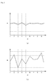
FIG. 5(a) illustrates a graph showing a detection result of the rotation speed - detection device according to an embodiment of the conventional case.
-
FIG. 5(b) illustrates a graph showing a detection result of the rotation speed detection device according to an embodiment of the present invention. - Hereinafter, an explanation will be given of a
turbocharger 1 according to an embodiment of the present invention with reference toFIG. 1 . - As shown in
FIG. 1 , theturbocharger 1 supplies, by using the discharge pressure of the exhaust gas exhausted from an engine (not shown) as a driving source, the pressurized and compressed intake air to the engine (not shown). Theturbocharger 1 includes a connectingmember 2, aturbine 6, acompressor 9, etc. - The connecting
member 2 connects theturbine 6 and thecompressor 9. The connectingmember 2 includes acenter housing 3, acoupling shaft 4,bearings 5, etc. Theturbine 6 is coupled to one end side of thecenter housing 3, whereas thecompressor 9 is coupled to the other end side of thecenter housing 3. Thecoupling shaft 4 connects an after-mentionedturbine wheel 8 and an after-mentionedcompressor wheel 11. Thecoupling shaft 4 is rotatably supported by thecenter housing 3 through thebearings 5. - The
turbine 6 converts the exhaust gas pressure of the engine (not shown) into rotational driving force. Theturbine 6 includes aturbine casing 7, theturbine wheel 8, etc. - The
turbine casing 7 is formed in a bottomed cylindrical shape. Thecenter housing 3 is coupled to one end side (bottomed side) of theturbine casing 7. An exhaustgas supply passage 7a in which exhaust gas is supplied to an outer periphery part thereof is formed on the one end side of theturbine casing 7. Anexhaust port 7b of the exhaust gas is formed on the other end side (opposite to the bottomed side) of theturbine casing 7. Thecoupling shaft 4 pierces the bottom part of theturbine casing 7. The exhaustgas supply passage 7a of theturbine casing 7 is formed to communicate with the interior portion of theturbine casing 7. - The
turbine wheel 8 is configured from aturbine hub 8a serving as a base of theturbine wheel 8, and a plurality ofturbine blades 8b arranged at regular intervals in a circumferential direction of anouter periphery surface 8c of theturbine hub 8a. Theturbine hub 8a is fixed to thecoupling shaft 4, thereby theturbine wheel 8 is rotatably supported by thecenter housing 3. At the end side opposite to thecoupling shaft 4 of theturbine hub 8a, theouter periphery surface 8c extends parallel to the shaft center of thecoupling shaft 4. Theouter periphery surface 8c is made up of a curved surface whose diameter increases toward thecoupling shaft 4 side. At thecoupling shaft 4 side end portion of theturbine hub 8a, aflange 8d extending perpendicular to the shaft center of thecoupling shaft 4 is formed. - The
turbine wheel 8 is disposed inside theturbine casing 7 in a state in which the outer periphery of theflange 8d of theturbine hub 8a (diametrically expansive side) is placed opposite to the exhaustgas supply passage 7a of theturbine casing 7, whereas the diametrically decreasing side end portion of theturbine hub 8a is placed opposite to theexhaust port 7b of theturbine casing 7. That is to say, theturbine wheel 8 is disposed such that the outer diameter of theturbine hub 8a is decreased from the supply side to the exhaust side of the exhaust gas. Because of this configuration, theturbine wheel 8 is rotated by the exhaust pressure of the exhaust gas supplied to the exhaustgas supply passage 7a. While theturbine wheel 8 is rotating, the exhaust gas is guided to a direction parallel to the rotational direction by theouter periphery surface 8c of theturbine hub 8a. Then, the exhaust gas is exhausted from theexhaust port 7b. - The
compressor 9 pressurizes and compresses the intake air of the engine. Thecompressor 9 includes acompressor casing 10, thecompressor wheel 11, etc. - The
compressor casing 10 is formed in a cylindrical shape. Thecenter housing 3 is coupled to one end side of thecompressor casing 10, thereby a bottom part of thecompressor casing 10 is formed. Thecoupling shaft 4 pierces the bottom part of thecompressor casing 10 formed by thecenter housing 3. An intakeair exhaust passage 10a in which the intake air is exhausted to the outer periphery part thereof is formed on the one end side (the bottomed side) of thecompressor casing 10. Asupply port 10b is formed on the other end side (opposite to the bottomed side) of thecompressor casing 10. Aninside wall 10c of thecompressor casing 10 is formed such that the inner diameter thereof is increased toward the one end side of thecompressor casing 10. Thereby the inside of thecompressor casing 10 is formed to communicate with the intakeair exhaust passage 10a. - The
compressor wheel 11 is configured from acompressor hub 11a serving as a base of thecompressor wheel 11, and a plurality offull blades 11b (whole blades) and a plurality ofsplitter blades 11c (short blades) arranged alternately at regular intervals in a circumferential direction of anouter periphery surface 11d of thecompressor hub 11a. - The
compressor hub 11a of thecompressor wheel 11 is fixed to thecoupling shaft 4, thereby thecompressor wheel 11 is rotatably supported by thecenter housing 3. That is to say, thecompressor wheel 11 is configured such that the rotative power from theturbine wheel 8 is transmitted to thecompressor wheel 11 through thecoupling shaft 4. At the end side opposite to thecoupling shaft 4 of thecompressor hub 11a, theouter periphery surface 11d extends parallel to the shaft center of thecoupling shaft 4. Theouter periphery surface 11d is made up of a curved surface whose diameter increases toward thecoupling shaft 4 side. At thecoupling shaft 4 side end portion of thecompressor hub 11a, a flange 11e extending perpendicular to the shaft center of thecoupling shaft 4 is formed. Thefull blades 11b (whole blades) and thesplitter blades 11c (short blades) are formed along theinside wall 10c of thecompressor casing 10 such that minute gaps are formed between outer edge shapes of theblades inside wall 10c. Moreover, the diametrically decreasing side end pdecreasingortions of thesplitter blades 11c are arranged more on diametrically expansive side than the diametrically decreasing side end portions of thefull blades 11b. Here, thesplitter blades 11c are not indispensable components of thecompressor wheel 11. - The
compressor wheel 11 is disposed inside thecompressor casing 10 in a state in which the outer periphery of the flange 11e of thecompressor hub 11a (diametrically decreasing side) is placed opposite to the intakeair exhaust passage 10a of thecompressor casing 10, whereas the diametrically decreased side end portion of thecompressor hub 11a is placed opposite to thesupply port 10b of thecompressor casing 10. That is to say, thecompressor wheel 11 is disposed such that the outer diameter of thecompressor hub 11a is increased from the supply side to the exhaust side of the intake air. Here, the gap between theinside wall 10c of thecompressor casing 10 and thecompressor hub 11a become narrower as approaching to the intakeair exhaust passage 10a. That is to say, inside thecompressor casing 10, an intakeair compress passage 11f (seeFIG. 2 ,FIG. 3 ) is formed by a space surrounded by theinside wall 10c of thecompressor casing 10, thefull blades 11b, thesplitter blades 11c, and theouter periphery surface 11d. - As mentioned above, with respect to the
turbocharger 1, when the exhaust gas is supplied to theturbine 6, theturbine wheel 8 is rotated by exhaust pressure. Thecompressor wheel 11 coupled to theturbine wheel 8 is rotated by the rotary drive power of theturbine wheel 8. Thecompressor wheel 11 takes intake air from thesupply port 10b of the intake air. The intake air is eliminated to the intakeair exhaust passage 10a through the intakeair compress passage 11f by thecompressor wheel 11. On this occasion, the intake air is pressurized and compressed at the intakeair compress passage 11f. As such, compression heat is generated. - Next, an explanation will be given of a rotation
speed detection device 12 according to an embodiment of the present invention with reference toFIG. 1 . - As shown in
FIG. 1 , the rotationspeed detection device 12 detects the rotation speed of thecompressor 9. The rotationspeed detection device 12 includes adetection unit 13, anamplifier 14, acontroller 15, etc. The rotationspeed detection device 12 detects the rotation speed of thecompressor 9 by detecting thefull blades 11b and thesplitter blades 11c by thedetection unit 13. - The
detection unit 13 detects thefull blades 11b and thesplitter blades 11c. Thedetection unit 13 is attached to thecompressor casing 10 by inserting into aninsertion hole 10d formed on the intakeair supply port 10b side of thecompressor casing 10. On this occasion, thedetection unit 13 is disposed such that the distal end of thedetection unit 13 does not project from theinside wall 10c of thecompressor casing 10. Thedetection unit 13 has a coil (not shown) for generating a magnetic field inside the approximately cylindrical shaped housing. Thedetection unit 13 detects the passing of thefull blades 11b and thesplitter blades 11c by detecting a change in the inductance. The change in the inductance occurs in response to the passing of thefull blades 11b and thesplitter blades 11c through the magnetic field generated by the coil. - The
amplifier 14 amplifies signals from thedetection unit 13. Theamplifier 14 is connected to thedetection unit 13, thereby signals from thedetection unit 13 are obtained. Theamplifier 14 amplifies signals from thedetection unit 13 and sends them to thecontroller 15. Thecontroller 15 calculates the rotating speed of thecompressor 9. Thecontroller 15 is connected to theamplifier 14, thereby thecontroller 15 obtains the amplified signals from theamplifier 14. Thecontroller 15 calculates the rotation speed of thecompressor 9 by using the amplified signals from theamplifier 14. - Next, an explanation will be given of the arranging place of the
detection unit 13 of the rotationspeed detection device 12 with reference toFIG. 2 to FIG. 4 . - In order to detect the
full blades 11b and thesplitter blades 11c which have different shapes, thedetection unit 13 has to be disposed such that both of thefull blades 11b and thesplitter blades 11c pass through the magnetic field. Accordingly, as shown inFIG. 2(a) , thedetection unit 13 has to be disposed in a state in which a region A is included in a region of the magnetic field. The region A is the region where both of thefull blades 11b and thesplitter blades 11c approach thecompressor casing 10. - Moreover, in order to improve detection accuracy, the
detection unit 13 has to be disposed in a region where pressurized and compressed intake air pressure and compression heat does not influence. Accordingly, as shown inFIG. 2(b) , thedetection unit 13 has to be disposed in a region where intake air taken in thecompressor casing 10 is not pressurized and compressed, that is, thedetection unit 13 has to be included in a region B where the pressure inside thecompressor casing 10 is in the range of a gauge pressure of one atmosphere or less. - As shown in
FIG. 3 , the range of the region B is determined by measuring the pressure inside thecompressor casing 10. A plurality ofmeasurement holes 10e are formed on thecompressor casing 10 along the intakeair compress passage 11f. The pressure inside thecompressor casing 10 at each position, that is, the pressure at each measurement holes 10e, is measured. Thereby, the pressure inside thecompressor casing 10 is determined. Specifically, abarometer 16 is inserted into eachmeasurement hole 10e so as to measure the pressure in the vicinity ofinside wall 10c of thecompressor casing 10. As such, the pressure in the intakeair compress passage 11f inside thecompressor casing 10 can be measured without contacting with thefull blades 11b and thesplitter blades 11c during rotation. The region B is determined on the basis of the measured pressure of the intakeair compress passage 11f. The barometer could be any type including mechanical type and bourdon tube type. - As described above, as shown in
FIG. 4 , thedetection unit 13 has to be disposed such that an overlap region C is included in the region of the magnetic field. The overlap region C is a region where both of thefull blades 11b and thesplitter blades 11c can be detected, and where the pressure inside thecompressor casing 10 is in the range of the gauge pressure of one atmosphere or less. By this arrangement, compared to the detection result (FIG. 5(a) ) of the conventional rotation speed detection device, the detection result of thedetection unit 13 is not affected by the pressure and compression heat. That is to say, thefull blades 11b and thesplitter blades 11c can be detected regardless of the operating state of the compressor (seeFIG. 5(b) ). - Furthermore, the
detection unit 13 defines, in the overlap region C, end portion D of thefull blade 11b or thesplitter blade 11c in which a length W (hereinafter, referred to as "blade width") from theouter periphery surface 11d of thecompressor hub 11a to the outer edge portion of thefull blade 11b or thesplitter blade 11c in its perpendicular direction becomes maximum as detection points. Since the position in which the blade width W becomes max in the overlap region C is included in the region of the magnetic field, thefull blades 11b and thesplitter blades 11c can be detected by thedetection unit 13 accurately without the influence of the pressure and compression heat. - As described above, the rotation
speed detection device 12 of thecompressor 9 is provided. With respect to the rotationspeed detection device 12, thedetection unit 13 for detecting thefull blades 11b and thesplitter blades 11c that are all blades approaching thecompressor casing 10 in response to the change in the inductance of the magnetic field is provided. Thedetection unit 13 is provided in the overlap region C in which thefull blades 11b and thesplitter blades 11c that are all blades can be detected and the exposure pressure is in the range of the gauge pressure of one atmosphere or less. Because of this configuration, when detecting thefull blades 11b and thesplitter blades 11c, the pressure and the compression heat of the pressurized and compressed intake air does not influence the detection result. As such, it is possible to achieve improved detection accuracy regardless of thecompressor 9 and the operating state of thecompressor 9. And it enables the prevention of the breakage of thedetection unit 13. - Moreover, the
detection unit 13 is provided in the overlap region C in which thefull blades 11b and thesplitter blades 11c that are all blades can be detected and the exposure pressure is in the range of the gauge pressure of one atmosphere or less. Thedetection unit 13 is provided such that end portions of thefull blades 11b and thesplitter blades 11c at which the blade width W of theouter periphery 11d of thecompressor hub 11a that supports thefull blades 11b and thesplitter blades 11c in the perpendicular direction is maximized are detected. - Because of this configuration, when detecting the
full blades 11b and thesplitter blades 11c, the pressure and the compression heat of the pressurized and compressed intake air does not influence the detection result. And the arrangement of thedetection unit 13 can easily be determined regardless of the shapes of thefull blades 11b and thesplitter blades 11c. As such, it is possible to achieve improved detection accuracy regardless of thecompressor 9 and the operating state of thecompressor 9. And it enables the prevention of the breakage of thedetection unit 13. - The rotation
speed detection device 12 of the present invention can be applied to an engine with turbocharger (a gasoline engine, or particularly a diesel engine). The present invention can be configured by attaching the detection unit 13 (turbo sensor) to thecompressor 9 of theturbocharger 1. As such, this configuration can be used for the technique of installation structure of the detection unit 13 (turbo sensor), whereby thedetection unit 13 is included in the rotationspeed detection device 12 of theturbocharger 1 of the engine. With regard to the rotationspeed detection device 12, the rotation speed of theturbocharger 1 of the engine is detected by thedetection unit 13. As such, it is possible to execute various controls of the engine, and it is possible to improve performance and quality of the engine. - The present invention is applicable to a rotation speed detection device of a compressor.
-
- 1
- turbocharger
- 9
- compressor
- 11b
- full blade
- 11c
- splitter blade
- 12
- rotation speed detection device
- 13
- detection unit
- C
- overlap region
Claims (2)
- A rotation speed detection device for a compressor, wherein a detection unit for detecting blades that are approaching a casing of the compressor in response to a change in the inductance of a magnetic field is provided, wherein
the detection unit is provided in an overlap region in which all of the blades can be detected and the exposure pressure is in the range of a gauge pressure of one atmosphere or less. - The rotation speed detection device according to Claim 1 wherein,
the detection unit is provided in an overlap region in which all of the blades can be detected and the exposure pressure is in the range of the gauge pressure of one atmosphere or less, wherein
the detection unit is provided such that end portions of the blades at which a blade width of the outer periphery of the compressor hub that support the blades in a perpendicular direction is maximized are detected.
Applications Claiming Priority (2)
| Application Number | Priority Date | Filing Date | Title |
|---|---|---|---|
| JP2012172397A JP5765855B2 (en) | 2012-08-02 | 2012-08-02 | Rotation speed detector |
| PCT/JP2013/070511 WO2014021276A1 (en) | 2012-08-02 | 2013-07-29 | Rotation speed detection device |
Publications (3)
| Publication Number | Publication Date |
|---|---|
| EP2881746A1 true EP2881746A1 (en) | 2015-06-10 |
| EP2881746A4 EP2881746A4 (en) | 2016-06-22 |
| EP2881746B1 EP2881746B1 (en) | 2019-06-26 |
Family
ID=50027951
Family Applications (1)
| Application Number | Title | Priority Date | Filing Date |
|---|---|---|---|
| EP13825012.1A Not-in-force EP2881746B1 (en) | 2012-08-02 | 2013-07-29 | Rotation speed detection device |
Country Status (5)
| Country | Link |
|---|---|
| US (1) | US10591506B2 (en) |
| EP (1) | EP2881746B1 (en) |
| JP (1) | JP5765855B2 (en) |
| CN (1) | CN104508496B (en) |
| WO (1) | WO2014021276A1 (en) |
Cited By (1)
| Publication number | Priority date | Publication date | Assignee | Title |
|---|---|---|---|---|
| DE102016203010A1 (en) | 2016-02-25 | 2017-08-31 | Volkswagen Aktiengesellschaft | Exhaust gas turbocharger with a compressor housing and a speed sensor |
Families Citing this family (3)
| Publication number | Priority date | Publication date | Assignee | Title |
|---|---|---|---|---|
| JP6436341B2 (en) * | 2014-11-04 | 2018-12-12 | ヤンマー株式会社 | Rotation speed detector |
| JP6436340B2 (en) * | 2014-11-04 | 2018-12-12 | ヤンマー株式会社 | Rotation speed detector |
| EP3392492A4 (en) * | 2015-12-16 | 2019-10-09 | Applied Electronics Corporation | INTERNAL COMBUSTION ENGINE |
Family Cites Families (26)
| Publication number | Priority date | Publication date | Assignee | Title |
|---|---|---|---|---|
| JPH09177555A (en) | 1995-12-27 | 1997-07-08 | Toyota Motor Corp | Supercharging pressure control device for supercharger |
| JP2003240788A (en) * | 2002-02-15 | 2003-08-27 | Mitsubishi Heavy Ind Ltd | Apparatus and method for detection of number-of- rotations per unit time of turbodevice |
| US20050017709A1 (en) * | 2003-07-25 | 2005-01-27 | Honeywell International Inc. | Magnetoresistive turbocharger compressor wheel speed sensor |
| JP4407288B2 (en) * | 2004-01-15 | 2010-02-03 | 株式会社デンソー | Supercharger position detection device |
| JP2005201146A (en) * | 2004-01-15 | 2005-07-28 | Denso Corp | Supercharger position detection device |
| JP2005265790A (en) * | 2004-03-22 | 2005-09-29 | Aec:Kk | Rotor detecting sensor |
| JP4478931B2 (en) * | 2004-07-06 | 2010-06-09 | 株式会社デンソー | Rotation speed detector |
| DE102005010921A1 (en) * | 2004-07-15 | 2006-02-09 | Siemens Ag | turbocharger |
| DE102004045618A1 (en) * | 2004-09-17 | 2006-04-13 | Siemens Ag | turbocharger |
| DE102004052695A1 (en) * | 2004-10-29 | 2007-05-10 | Siemens Ag | turbocharger |
| DE102005029764B4 (en) * | 2005-06-27 | 2010-11-11 | Continental Automotive France | Sensor for measuring the speed of a turbo shaft |
| JP5240888B2 (en) * | 2006-01-25 | 2013-07-17 | 株式会社日本自動車部品総合研究所 | Motion detection device |
| US7696746B2 (en) * | 2006-01-25 | 2010-04-13 | Denso Corporation | Motion detecting apparatus |
| JP4644144B2 (en) * | 2006-02-28 | 2011-03-02 | 株式会社デンソー | Eddy current type conductor detector |
| JP2007321687A (en) * | 2006-06-02 | 2007-12-13 | Denso Corp | Control device for turbocharged internal combustion engine |
| JP2008014656A (en) | 2006-07-03 | 2008-01-24 | Denso Corp | Rotation speed detector |
| DE102006040667B3 (en) * | 2006-08-30 | 2008-01-10 | Siemens Ag | Waste gate actuator for an exhaust gas turbocharger |
| DE102010003347B4 (en) * | 2009-05-20 | 2021-08-05 | Robert Bosch Gmbh | Method and device for determining one or more speeds of a charging device, in particular for an internal combustion engine |
| DE102009027853A1 (en) * | 2009-07-21 | 2011-01-27 | Zf Friedrichshafen Ag | Rotation-speed sensor for use in exhaust-gas turbocharger to detect speed in high temperature region, has component adjacent to magnetic field sensitive elements to protect elements from heating effect |
| JP2011241733A (en) * | 2010-05-17 | 2011-12-01 | Isuzu Motors Ltd | Revolution speed detection device of turbocharger |
| US8579591B2 (en) * | 2010-10-28 | 2013-11-12 | Hamilton Sundstrand Corporation | Centrifugal compressor impeller |
| US9869249B2 (en) * | 2012-01-31 | 2018-01-16 | United Technologies Corporation | Speed sensor probe location in gas turbine engine |
| DE102012222202A1 (en) * | 2012-12-04 | 2014-06-05 | Robert Bosch Gmbh | Method for monitoring a rotation of a compressor wheel |
| JP6398940B2 (en) * | 2015-10-07 | 2018-10-03 | 株式会社デンソー | Rotation speed detector |
| EP3406113B1 (en) * | 2016-01-20 | 2020-09-09 | Jaquet Technology Group AG | Manufacturing method for a sensing element and sensor device |
| JP6926502B2 (en) * | 2017-02-10 | 2021-08-25 | 日立金属株式会社 | Rotation sensor for turbo and turbocharger |
-
2012
- 2012-08-02 JP JP2012172397A patent/JP5765855B2/en not_active Expired - Fee Related
-
2013
- 2013-07-29 EP EP13825012.1A patent/EP2881746B1/en not_active Not-in-force
- 2013-07-29 CN CN201380040753.9A patent/CN104508496B/en not_active Expired - Fee Related
- 2013-07-29 US US14/418,554 patent/US10591506B2/en not_active Expired - Fee Related
- 2013-07-29 WO PCT/JP2013/070511 patent/WO2014021276A1/en not_active Ceased
Cited By (2)
| Publication number | Priority date | Publication date | Assignee | Title |
|---|---|---|---|---|
| DE102016203010A1 (en) | 2016-02-25 | 2017-08-31 | Volkswagen Aktiengesellschaft | Exhaust gas turbocharger with a compressor housing and a speed sensor |
| DE102016203010B4 (en) | 2016-02-25 | 2018-09-13 | Volkswagen Aktiengesellschaft | Exhaust gas turbocharger with a compressor housing and a speed sensor |
Also Published As
| Publication number | Publication date |
|---|---|
| JP5765855B2 (en) | 2015-08-19 |
| CN104508496A (en) | 2015-04-08 |
| US10591506B2 (en) | 2020-03-17 |
| EP2881746B1 (en) | 2019-06-26 |
| CN104508496B (en) | 2018-04-27 |
| US20150198624A1 (en) | 2015-07-16 |
| EP2881746A4 (en) | 2016-06-22 |
| WO2014021276A1 (en) | 2014-02-06 |
| JP2014032091A (en) | 2014-02-20 |
Similar Documents
| Publication | Publication Date | Title |
|---|---|---|
| EP2881746B1 (en) | Rotation speed detection device | |
| CN102985641A (en) | Method for adjusting the radial gap between blade tips of turbine blades and a channel wall, and device for measuring a radial gap of an axially permeable turbomachine | |
| CN101563588B (en) | Method for non-contacting blade oscillation measurement | |
| US9279336B2 (en) | High temperature split-face probe | |
| JP2008544131A (en) | Detection of engine status using an external microphone | |
| US20140356166A1 (en) | Clearance measuring sensor with abradable electrode | |
| JP5645207B2 (en) | Eddy current sensor and turbocharger rotation detection device using the same | |
| RU2593427C2 (en) | Device and method of measuring propagation time of tops of blades in turbine machine | |
| KR101920945B1 (en) | A device and a method for monitoring a roter | |
| RU2451279C1 (en) | Method of diagnosing resonance vibrations in axial turbomachine impeller vanes | |
| EP3447264A1 (en) | Unbalance detecting device and unbalance detecting method | |
| US7417398B2 (en) | Vacuum pump | |
| KR20200002952A (en) | Blade vibration monitoring device, blade vibration monitoring system, rotor blade, and rotary machine | |
| CN212690314U (en) | An air compressor performance test device | |
| RU2287141C2 (en) | Method for diagnostics of oscillations of working wheel of turbo-machine | |
| CN104334849A (en) | Exhaust-gas turbocharger | |
| US20120197579A1 (en) | Method for determining bearing play of exhaust-gas-turbocharger friction bearings | |
| RU2411466C1 (en) | Method of detecting resonance oscillations of turbo-machine rotor blades | |
| CN121039378A (en) | Measuring movement or force in the deceleration device of an aircraft propulsion system | |
| KR20150119873A (en) | Power determination method and turbomachine | |
| US8206078B2 (en) | System and method for monitoring radial motion of a rotating shaft of a turbocharger | |
| CN113358210B (en) | A pressure pulsation-based vibration monitoring method for turbocharger turbine blades | |
| US20150056077A1 (en) | Detection system for identifying blockages in guide vanes of a turbine engine | |
| JP2018146385A (en) | Blade monitoring device and rotating machine system | |
| CN107923257A (en) | Drive ring offset sensing system, compressor and gas turbine |
Legal Events
| Date | Code | Title | Description |
|---|---|---|---|
| PUAI | Public reference made under article 153(3) epc to a published international application that has entered the european phase |
Free format text: ORIGINAL CODE: 0009012 |
|
| 17P | Request for examination filed |
Effective date: 20150302 |
|
| AK | Designated contracting states |
Kind code of ref document: A1 Designated state(s): AL AT BE BG CH CY CZ DE DK EE ES FI FR GB GR HR HU IE IS IT LI LT LU LV MC MK MT NL NO PL PT RO RS SE SI SK SM TR |
|
| AX | Request for extension of the european patent |
Extension state: BA ME |
|
| DAX | Request for extension of the european patent (deleted) | ||
| RA4 | Supplementary search report drawn up and despatched (corrected) |
Effective date: 20160524 |
|
| RIC1 | Information provided on ipc code assigned before grant |
Ipc: F04D 27/00 20060101ALI20160518BHEP Ipc: G01P 3/49 20060101AFI20160518BHEP Ipc: F02B 39/16 20060101ALI20160518BHEP Ipc: F01D 21/02 20060101ALI20160518BHEP Ipc: F01D 17/06 20060101ALI20160518BHEP Ipc: G01P 3/481 20060101ALI20160518BHEP Ipc: F02B 37/12 20060101ALI20160518BHEP Ipc: F01D 21/04 20060101ALI20160518BHEP |
|
| STAA | Information on the status of an ep patent application or granted ep patent |
Free format text: STATUS: EXAMINATION IS IN PROGRESS |
|
| 17Q | First examination report despatched |
Effective date: 20180803 |
|
| GRAP | Despatch of communication of intention to grant a patent |
Free format text: ORIGINAL CODE: EPIDOSNIGR1 |
|
| STAA | Information on the status of an ep patent application or granted ep patent |
Free format text: STATUS: GRANT OF PATENT IS INTENDED |
|
| INTG | Intention to grant announced |
Effective date: 20190205 |
|
| GRAS | Grant fee paid |
Free format text: ORIGINAL CODE: EPIDOSNIGR3 |
|
| GRAA | (expected) grant |
Free format text: ORIGINAL CODE: 0009210 |
|
| STAA | Information on the status of an ep patent application or granted ep patent |
Free format text: STATUS: THE PATENT HAS BEEN GRANTED |
|
| AK | Designated contracting states |
Kind code of ref document: B1 Designated state(s): AL AT BE BG CH CY CZ DE DK EE ES FI FR GB GR HR HU IE IS IT LI LT LU LV MC MK MT NL NO PL PT RO RS SE SI SK SM TR |
|
| REG | Reference to a national code |
Ref country code: GB Ref legal event code: FG4D |
|
| RIN1 | Information on inventor provided before grant (corrected) |
Inventor name: NOMURA HIDENORI Inventor name: TAKAHASHI TAKESHI Inventor name: ITATSU TOSHIRO Inventor name: YAMADA KAZUHIRO Inventor name: HIBINO MITSUHIRO |
|
| REG | Reference to a national code |
Ref country code: CH Ref legal event code: EP |
|
| REG | Reference to a national code |
Ref country code: AT Ref legal event code: REF Ref document number: 1148906 Country of ref document: AT Kind code of ref document: T Effective date: 20190715 |
|
| REG | Reference to a national code |
Ref country code: IE Ref legal event code: FG4D |
|
| REG | Reference to a national code |
Ref country code: DE Ref legal event code: R096 Ref document number: 602013057196 Country of ref document: DE |
|
| RAP2 | Party data changed (patent owner data changed or rights of a patent transferred) |
Owner name: YANMAR CO., LTD. Owner name: TOYOTA JIDOSHA KABUSHIKI KAISHA |
|
| REG | Reference to a national code |
Ref country code: NL Ref legal event code: MP Effective date: 20190626 |
|
| PG25 | Lapsed in a contracting state [announced via postgrant information from national office to epo] |
Ref country code: NO Free format text: LAPSE BECAUSE OF FAILURE TO SUBMIT A TRANSLATION OF THE DESCRIPTION OR TO PAY THE FEE WITHIN THE PRESCRIBED TIME-LIMIT Effective date: 20190926 Ref country code: LT Free format text: LAPSE BECAUSE OF FAILURE TO SUBMIT A TRANSLATION OF THE DESCRIPTION OR TO PAY THE FEE WITHIN THE PRESCRIBED TIME-LIMIT Effective date: 20190626 Ref country code: FI Free format text: LAPSE BECAUSE OF FAILURE TO SUBMIT A TRANSLATION OF THE DESCRIPTION OR TO PAY THE FEE WITHIN THE PRESCRIBED TIME-LIMIT Effective date: 20190626 Ref country code: SE Free format text: LAPSE BECAUSE OF FAILURE TO SUBMIT A TRANSLATION OF THE DESCRIPTION OR TO PAY THE FEE WITHIN THE PRESCRIBED TIME-LIMIT Effective date: 20190626 Ref country code: HR Free format text: LAPSE BECAUSE OF FAILURE TO SUBMIT A TRANSLATION OF THE DESCRIPTION OR TO PAY THE FEE WITHIN THE PRESCRIBED TIME-LIMIT Effective date: 20190626 Ref country code: AL Free format text: LAPSE BECAUSE OF FAILURE TO SUBMIT A TRANSLATION OF THE DESCRIPTION OR TO PAY THE FEE WITHIN THE PRESCRIBED TIME-LIMIT Effective date: 20190626 |
|
| REG | Reference to a national code |
Ref country code: LT Ref legal event code: MG4D |
|
| PG25 | Lapsed in a contracting state [announced via postgrant information from national office to epo] |
Ref country code: GR Free format text: LAPSE BECAUSE OF FAILURE TO SUBMIT A TRANSLATION OF THE DESCRIPTION OR TO PAY THE FEE WITHIN THE PRESCRIBED TIME-LIMIT Effective date: 20190927 Ref country code: BG Free format text: LAPSE BECAUSE OF FAILURE TO SUBMIT A TRANSLATION OF THE DESCRIPTION OR TO PAY THE FEE WITHIN THE PRESCRIBED TIME-LIMIT Effective date: 20190926 Ref country code: RS Free format text: LAPSE BECAUSE OF FAILURE TO SUBMIT A TRANSLATION OF THE DESCRIPTION OR TO PAY THE FEE WITHIN THE PRESCRIBED TIME-LIMIT Effective date: 20190626 Ref country code: LV Free format text: LAPSE BECAUSE OF FAILURE TO SUBMIT A TRANSLATION OF THE DESCRIPTION OR TO PAY THE FEE WITHIN THE PRESCRIBED TIME-LIMIT Effective date: 20190626 |
|
| REG | Reference to a national code |
Ref country code: AT Ref legal event code: MK05 Ref document number: 1148906 Country of ref document: AT Kind code of ref document: T Effective date: 20190626 |
|
| PG25 | Lapsed in a contracting state [announced via postgrant information from national office to epo] |
Ref country code: EE Free format text: LAPSE BECAUSE OF FAILURE TO SUBMIT A TRANSLATION OF THE DESCRIPTION OR TO PAY THE FEE WITHIN THE PRESCRIBED TIME-LIMIT Effective date: 20190626 Ref country code: SK Free format text: LAPSE BECAUSE OF FAILURE TO SUBMIT A TRANSLATION OF THE DESCRIPTION OR TO PAY THE FEE WITHIN THE PRESCRIBED TIME-LIMIT Effective date: 20190626 Ref country code: PT Free format text: LAPSE BECAUSE OF FAILURE TO SUBMIT A TRANSLATION OF THE DESCRIPTION OR TO PAY THE FEE WITHIN THE PRESCRIBED TIME-LIMIT Effective date: 20191028 Ref country code: CZ Free format text: LAPSE BECAUSE OF FAILURE TO SUBMIT A TRANSLATION OF THE DESCRIPTION OR TO PAY THE FEE WITHIN THE PRESCRIBED TIME-LIMIT Effective date: 20190626 Ref country code: NL Free format text: LAPSE BECAUSE OF FAILURE TO SUBMIT A TRANSLATION OF THE DESCRIPTION OR TO PAY THE FEE WITHIN THE PRESCRIBED TIME-LIMIT Effective date: 20190626 Ref country code: AT Free format text: LAPSE BECAUSE OF FAILURE TO SUBMIT A TRANSLATION OF THE DESCRIPTION OR TO PAY THE FEE WITHIN THE PRESCRIBED TIME-LIMIT Effective date: 20190626 Ref country code: RO Free format text: LAPSE BECAUSE OF FAILURE TO SUBMIT A TRANSLATION OF THE DESCRIPTION OR TO PAY THE FEE WITHIN THE PRESCRIBED TIME-LIMIT Effective date: 20190626 |
|
| PG25 | Lapsed in a contracting state [announced via postgrant information from national office to epo] |
Ref country code: ES Free format text: LAPSE BECAUSE OF FAILURE TO SUBMIT A TRANSLATION OF THE DESCRIPTION OR TO PAY THE FEE WITHIN THE PRESCRIBED TIME-LIMIT Effective date: 20190626 Ref country code: IS Free format text: LAPSE BECAUSE OF FAILURE TO SUBMIT A TRANSLATION OF THE DESCRIPTION OR TO PAY THE FEE WITHIN THE PRESCRIBED TIME-LIMIT Effective date: 20191026 Ref country code: SM Free format text: LAPSE BECAUSE OF FAILURE TO SUBMIT A TRANSLATION OF THE DESCRIPTION OR TO PAY THE FEE WITHIN THE PRESCRIBED TIME-LIMIT Effective date: 20190626 Ref country code: IT Free format text: LAPSE BECAUSE OF FAILURE TO SUBMIT A TRANSLATION OF THE DESCRIPTION OR TO PAY THE FEE WITHIN THE PRESCRIBED TIME-LIMIT Effective date: 20190626 |
|
| REG | Reference to a national code |
Ref country code: CH Ref legal event code: PL |
|
| PG25 | Lapsed in a contracting state [announced via postgrant information from national office to epo] |
Ref country code: MC Free format text: LAPSE BECAUSE OF FAILURE TO SUBMIT A TRANSLATION OF THE DESCRIPTION OR TO PAY THE FEE WITHIN THE PRESCRIBED TIME-LIMIT Effective date: 20190626 Ref country code: TR Free format text: LAPSE BECAUSE OF FAILURE TO SUBMIT A TRANSLATION OF THE DESCRIPTION OR TO PAY THE FEE WITHIN THE PRESCRIBED TIME-LIMIT Effective date: 20190626 |
|
| REG | Reference to a national code |
Ref country code: BE Ref legal event code: MM Effective date: 20190731 |
|
| PG25 | Lapsed in a contracting state [announced via postgrant information from national office to epo] |
Ref country code: PL Free format text: LAPSE BECAUSE OF FAILURE TO SUBMIT A TRANSLATION OF THE DESCRIPTION OR TO PAY THE FEE WITHIN THE PRESCRIBED TIME-LIMIT Effective date: 20190626 Ref country code: DK Free format text: LAPSE BECAUSE OF FAILURE TO SUBMIT A TRANSLATION OF THE DESCRIPTION OR TO PAY THE FEE WITHIN THE PRESCRIBED TIME-LIMIT Effective date: 20190626 |
|
| PG25 | Lapsed in a contracting state [announced via postgrant information from national office to epo] |
Ref country code: IS Free format text: LAPSE BECAUSE OF FAILURE TO SUBMIT A TRANSLATION OF THE DESCRIPTION OR TO PAY THE FEE WITHIN THE PRESCRIBED TIME-LIMIT Effective date: 20200224 Ref country code: CH Free format text: LAPSE BECAUSE OF NON-PAYMENT OF DUE FEES Effective date: 20190731 Ref country code: LI Free format text: LAPSE BECAUSE OF NON-PAYMENT OF DUE FEES Effective date: 20190731 Ref country code: LU Free format text: LAPSE BECAUSE OF NON-PAYMENT OF DUE FEES Effective date: 20190729 Ref country code: BE Free format text: LAPSE BECAUSE OF NON-PAYMENT OF DUE FEES Effective date: 20190731 |
|
| REG | Reference to a national code |
Ref country code: DE Ref legal event code: R097 Ref document number: 602013057196 Country of ref document: DE |
|
| PLBE | No opposition filed within time limit |
Free format text: ORIGINAL CODE: 0009261 |
|
| STAA | Information on the status of an ep patent application or granted ep patent |
Free format text: STATUS: NO OPPOSITION FILED WITHIN TIME LIMIT |
|
| PG2D | Information on lapse in contracting state deleted |
Ref country code: IS |
|
| PG25 | Lapsed in a contracting state [announced via postgrant information from national office to epo] |
Ref country code: IE Free format text: LAPSE BECAUSE OF NON-PAYMENT OF DUE FEES Effective date: 20190729 |
|
| 26N | No opposition filed |
Effective date: 20200603 |
|
| PG25 | Lapsed in a contracting state [announced via postgrant information from national office to epo] |
Ref country code: SI Free format text: LAPSE BECAUSE OF FAILURE TO SUBMIT A TRANSLATION OF THE DESCRIPTION OR TO PAY THE FEE WITHIN THE PRESCRIBED TIME-LIMIT Effective date: 20190626 |
|
| REG | Reference to a national code |
Ref country code: DE Ref legal event code: R082 Ref document number: 602013057196 Country of ref document: DE Representative=s name: JOSTARNDT PATENTANWALTS-AG, DE Ref country code: DE Ref legal event code: R081 Ref document number: 602013057196 Country of ref document: DE Owner name: TOYOTA JIDOSHA KABUSHIKI KAISHA, TOYOTA-SHI, JP Free format text: FORMER OWNERS: TOYOTA JIDOSHA KABUSHIKI KAISHA, TOYOTA-SHI, AICHI-KEN, JP; YANMAR CO., LTD., OSAKA, JP Ref country code: DE Ref legal event code: R081 Ref document number: 602013057196 Country of ref document: DE Owner name: YANMAR POWER TECHNOLOGY CO., LTD., JP Free format text: FORMER OWNERS: TOYOTA JIDOSHA KABUSHIKI KAISHA, TOYOTA-SHI, AICHI-KEN, JP; YANMAR CO., LTD., OSAKA, JP |
|
| PGFP | Annual fee paid to national office [announced via postgrant information from national office to epo] |
Ref country code: DE Payment date: 20200721 Year of fee payment: 8 Ref country code: GB Payment date: 20200727 Year of fee payment: 8 Ref country code: FR Payment date: 20200723 Year of fee payment: 8 |
|
| PG25 | Lapsed in a contracting state [announced via postgrant information from national office to epo] |
Ref country code: CY Free format text: LAPSE BECAUSE OF FAILURE TO SUBMIT A TRANSLATION OF THE DESCRIPTION OR TO PAY THE FEE WITHIN THE PRESCRIBED TIME-LIMIT Effective date: 20190626 |
|
| PG25 | Lapsed in a contracting state [announced via postgrant information from national office to epo] |
Ref country code: MT Free format text: LAPSE BECAUSE OF FAILURE TO SUBMIT A TRANSLATION OF THE DESCRIPTION OR TO PAY THE FEE WITHIN THE PRESCRIBED TIME-LIMIT Effective date: 20190626 Ref country code: HU Free format text: LAPSE BECAUSE OF FAILURE TO SUBMIT A TRANSLATION OF THE DESCRIPTION OR TO PAY THE FEE WITHIN THE PRESCRIBED TIME-LIMIT; INVALID AB INITIO Effective date: 20130729 |
|
| REG | Reference to a national code |
Ref country code: DE Ref legal event code: R119 Ref document number: 602013057196 Country of ref document: DE |
|
| GBPC | Gb: european patent ceased through non-payment of renewal fee |
Effective date: 20210729 |
|
| PG25 | Lapsed in a contracting state [announced via postgrant information from national office to epo] |
Ref country code: GB Free format text: LAPSE BECAUSE OF NON-PAYMENT OF DUE FEES Effective date: 20210729 Ref country code: DE Free format text: LAPSE BECAUSE OF NON-PAYMENT OF DUE FEES Effective date: 20220201 |
|
| PG25 | Lapsed in a contracting state [announced via postgrant information from national office to epo] |
Ref country code: FR Free format text: LAPSE BECAUSE OF NON-PAYMENT OF DUE FEES Effective date: 20210731 |
|
| PG25 | Lapsed in a contracting state [announced via postgrant information from national office to epo] |
Ref country code: MK Free format text: LAPSE BECAUSE OF FAILURE TO SUBMIT A TRANSLATION OF THE DESCRIPTION OR TO PAY THE FEE WITHIN THE PRESCRIBED TIME-LIMIT Effective date: 20190626 |