EP2881328A1 - Aircraft fuel system with heating of stored fuel - Google Patents
Aircraft fuel system with heating of stored fuel Download PDFInfo
- Publication number
- EP2881328A1 EP2881328A1 EP13005615.3A EP13005615A EP2881328A1 EP 2881328 A1 EP2881328 A1 EP 2881328A1 EP 13005615 A EP13005615 A EP 13005615A EP 2881328 A1 EP2881328 A1 EP 2881328A1
- Authority
- EP
- European Patent Office
- Prior art keywords
- fuel
- arrangement
- tank
- collector
- heat
- Prior art date
- Legal status (The legal status is an assumption and is not a legal conclusion. Google has not performed a legal analysis and makes no representation as to the accuracy of the status listed.)
- Granted
Links
Images

Classifications
-
- B—PERFORMING OPERATIONS; TRANSPORTING
- B64—AIRCRAFT; AVIATION; COSMONAUTICS
- B64D—EQUIPMENT FOR FITTING IN OR TO AIRCRAFT; FLIGHT SUITS; PARACHUTES; ARRANGEMENT OR MOUNTING OF POWER PLANTS OR PROPULSION TRANSMISSIONS IN AIRCRAFT
- B64D37/00—Arrangements in connection with fuel supply for power plant
- B64D37/34—Conditioning fuel, e.g. heating
-
- B—PERFORMING OPERATIONS; TRANSPORTING
- B64—AIRCRAFT; AVIATION; COSMONAUTICS
- B64D—EQUIPMENT FOR FITTING IN OR TO AIRCRAFT; FLIGHT SUITS; PARACHUTES; ARRANGEMENT OR MOUNTING OF POWER PLANTS OR PROPULSION TRANSMISSIONS IN AIRCRAFT
- B64D37/00—Arrangements in connection with fuel supply for power plant
-
- B—PERFORMING OPERATIONS; TRANSPORTING
- B64—AIRCRAFT; AVIATION; COSMONAUTICS
- B64D—EQUIPMENT FOR FITTING IN OR TO AIRCRAFT; FLIGHT SUITS; PARACHUTES; ARRANGEMENT OR MOUNTING OF POWER PLANTS OR PROPULSION TRANSMISSIONS IN AIRCRAFT
- B64D37/00—Arrangements in connection with fuel supply for power plant
- B64D37/02—Tanks
- B64D37/04—Arrangement thereof in or on aircraft
-
- F—MECHANICAL ENGINEERING; LIGHTING; HEATING; WEAPONS; BLASTING
- F02—COMBUSTION ENGINES; HOT-GAS OR COMBUSTION-PRODUCT ENGINE PLANTS
- F02C—GAS-TURBINE PLANTS; AIR INTAKES FOR JET-PROPULSION PLANTS; CONTROLLING FUEL SUPPLY IN AIR-BREATHING JET-PROPULSION PLANTS
- F02C7/00—Features, components parts, details or accessories, not provided for in, or of interest apart form groups F02C1/00 - F02C6/00; Air intakes for jet-propulsion plants
- F02C7/22—Fuel supply systems
- F02C7/224—Heating fuel before feeding to the burner
-
- F—MECHANICAL ENGINEERING; LIGHTING; HEATING; WEAPONS; BLASTING
- F05—INDEXING SCHEMES RELATING TO ENGINES OR PUMPS IN VARIOUS SUBCLASSES OF CLASSES F01-F04
- F05D—INDEXING SCHEME FOR ASPECTS RELATING TO NON-POSITIVE-DISPLACEMENT MACHINES OR ENGINES, GAS-TURBINES OR JET-PROPULSION PLANTS
- F05D2260/00—Function
- F05D2260/20—Heat transfer, e.g. cooling
- F05D2260/213—Heat transfer, e.g. cooling by the provision of a heat exchanger within the cooling circuit
-
- Y—GENERAL TAGGING OF NEW TECHNOLOGICAL DEVELOPMENTS; GENERAL TAGGING OF CROSS-SECTIONAL TECHNOLOGIES SPANNING OVER SEVERAL SECTIONS OF THE IPC; TECHNICAL SUBJECTS COVERED BY FORMER USPC CROSS-REFERENCE ART COLLECTIONS [XRACs] AND DIGESTS
- Y02—TECHNOLOGIES OR APPLICATIONS FOR MITIGATION OR ADAPTATION AGAINST CLIMATE CHANGE
- Y02T—CLIMATE CHANGE MITIGATION TECHNOLOGIES RELATED TO TRANSPORTATION
- Y02T50/00—Aeronautics or air transport
- Y02T50/60—Efficient propulsion technologies, e.g. for aircraft
Definitions
- the invention relates to fuel systems for aircraft, particularly, although not exclusively, fixed-wing aircraft.
- Aircraft flying for extended periods of time in low temperatures may be subject to freezing of fuel within fuel storage tanks. In very cold environments this can be a particular problem at lower altitudes as a result of the higher air pressure and air density that occur at lower altitudes, compared to higher altitudes, which leads to more rapid heat loss. In fixed-wing aircraft having fuel storage tanks integrated into the wings, fuel freezing within such tanks during extended flying in low temperatures is very likely. This is a particular problem where the wings have a low aspect ratio, due to the relatively high surface area of the wings in relation to fuel tank volume.
- the present invention provides an aircraft fuel system characterised by a fuel storage tank arrangement, a collector fuel tank arrangement, a first fuel line connecting the fuel storage tank arrangement to the collector fuel tank arrangement and a second fuel line connecting the collector fuel tank arrangement to an aircraft engine in use of the system, wherein the system further comprises a first heat-transfer arrangement arranged to transfer heat energy within unspent fuel output from the aircraft engine to fuel within the fuel storage tank arrangement.
- heat energy within unspent fuel output by the aircraft engine is used to heat fuel within the fuel storage tank arrangement, instead of simply being wasted. This reduces the likelihood of fuel freezing within the fuel storage tank arrangement, without the need for dedicated heating and/or insulation apparatus.
- the system further comprises a second heat-transfer arrangement arranged to transfer heat energy from aircraft electronic and/or computer equipment to fuel within the fuel storage tank arrangement.
- a second heat-transfer arrangement arranged to transfer heat energy from aircraft electronic and/or computer equipment to fuel within the fuel storage tank arrangement. This provides additional heating of fuel within the fuel storage tank arrangement using further waste heat from aircraft electronic and/or computer equipment and further reduces the likelihood of fuel freezing within the fuel storage tank arrangement.
- a third fuel line may connect the aircraft engine to the collector fuel tank arrangement in use of the system, whereby at least a portion of unspent fuel output by the aircraft engine is returned to the collector fuel tank arrangement, the first heat-transfer arrangement comprising:
- the fuel storage tank arrangement may comprise a fuselage fuel tank and a wing fuel tank connected by a fuel line, the first fuel line connecting the fuselage fuel tank to the collector tank arrangement, and the fuel line arrangement being arranged to draw fuel from, and return that fuel to, the wing fuel tank.
- the fuel storage tank arrangement comprises a wing fuel tank and a fuselage fuel tank, it is fuel in the wing fuel tank that is most susceptible to freezing because the limited space within an aircraft wing means that measures such as providing insulation may be difficult or impossible to apply.
- the first heat-transfer arrangement may comprise a third fuel line connecting the aircraft engine to the fuel storage tank arrangement in use of the system, whereby at least a portion of unspent fuel output by the aircraft engine is returned directly to the fuel storage tank arrangement.
- This is a particularly efficient arrangement for transferring heat within unspent fuel to the fuel storage tank arrangement because heat within unspent fuel is transferred to the fuel storage tank arrangement by movement of the unpsent fuel itself.
- the fuel storage tank arrangement comprises a fuselage fuel tank and a wing fuel tank connected by a fuel line
- the first fuel line may connect the fuselage fuel tank to the collector fuel tank arrangement, the third fuel line connecting the aircraft engine to the wing fuel tank.
- the second heat-transfer arrangement conveniently comprises a fuel line arrangement arranged to draw fuel from, and return that fuel to, the fuel storage tank arrangement and a heat-exchanger arranged to couple heat from the aircraft electronic and/or computer equipment to fuel within the fuel line arrangement.
- the heat-exchanger is in thermal contact with a compressor arranged to compress a refrigerant fluid within a cooling circuit for cooling the aircraft electronic and/or computer equipment. This allows waste heat collected by the refrigerant to be efficiently coupled to the heat exchanger in addition to waste heat from the compressor itself.
- the fuel storage tank arrangement comprises a fuselage fuel tank and a wing fuel tank connected by a fuel line
- the first fuel line connects the fuselage fuel tank to the collector tank arrangement, the fuel line arrangement being arranged to draw fuel from, and return that fuel to, the wing fuel tank. Again, this provides for waste heat to be directed to the wing fuel tank which is more susceptible to fuel freezing.
- the collector fuel tank arrangement may be either a simplex collector tank or a duplex collector tank.
- fuel line in this specification may indicate not only a single physical fuel line or fuel pipe, but possibly also a fuel route comprising two or more individual fuel lines or fuel pipes, including any appropriate valves, arranged in combination to transport fuel within the fuel system.
- a fuel system 100 of the invention comprises a fuel storage tank arrangement comprising a fuselage fuel tank 102 and two wing fuel tanks 104, 106 each of which are connected to the fuselage fuel tank by a respective fuel line 107, 109.
- the fuselage fuel tank 102 is connected to a collector fuel tank 108 by a first fuel line 101.
- Fuel is provided to aircraft engines in use of the system 100 from the collector fuel tank 108 via second fuel lines 103A, 103B. Unspent fuel output from the aircraft engines is returned to the collector fuel tank 108 during operation of the system 100, via third fuel lines 105A, 105B which pass through a heat exchanger 110.
- a fuel line arrangement consisting of individual fuel lines 111A, 111B, 111C is arranged to draw fuel from the wing fuel tanks 104, 106 and to return that fuel to the wing tanks 104, 106.
- the fuel line 111B passes through the heat exchanger 110 which is arranged to couple heat from unspent fuel output by the aircraft engines within fuel lines 105A, 105B to fuel within the fuel line 111B.
- fuel drawn from the wing fuel tanks 104, 106 is heated using heat within unspent fuel output by the aircraft engines, and then returned to the wing fuel tanks 104, 106, thus reducing the likelihood of fuel freezing within the wing fuel tanks 104, 106.
- the system 100 further comprises a secondary heater exchanger 112 arranged to couple waste heat from aircraft electronic and/or computer equipment 118 to fuel within the fuel line 111B. Waste heat from the electronic and/or computer equipment 118 is conveyed to the secondary heat exchanger 112 via refrigerant within a cooling circuit 113. Heat within the refrigerant is coupled to the heat exchanger 112 upon compression within a compressor 116 which is in thermal contact with the heat exchanger 212. An air condenser 114 within the cooling circuit 113 provides a cold source to the electronic and/or computer equipment 118 in the event that fuel drawn from the wing tanks 104, 106 is very hot and/or there is little fuel in the wing tanks 104, 106 such that fuel within fuel line 111B cannot receive more heat.
- fuel drawn from the wing tanks 104, 106 is heated within fuel line 111B using waste heat within unspent fuel output from the aircraft engines, and also using waste heat from the aircraft electronic and/or computer equipment 118, and then returned to the wing fuel tanks 104, 106, thus reducing the likelihood of fuel freezing within these fuel tanks during extended flying in cold environments.
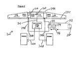
- FIG. 2 shows a second example fuel system of the invention indicated generally by 200.
- a fuel line arrangement consisting of individual fuel lines 211A, 211B, 211C is arranged to draw fuel from wing fuel tanks 204, 206 and to return it to these tanks.
- Fuel line 211B passes through a heat exchanger 212 which couples waste heat from aircraft electronic and/or computer equipment 218 to fuel in fuel line 211B by means of a cooling circuit 213 comprising refrigerant fluid which is compressed by a compressor 216, the compressor 216 being in thermal contact with the heat exchanger 212.
- the system 200 of Figure 2 operates similarly to the system 100 of Figure 1 , except that unspent fuel output by the aircraft engines is returned directly to wing fuel tanks 204, 206, via fuel lines 215A, 215B, 211C, rather than being returned to the collector fuel tank 208.
- a heat exchanger for thermally coupling fuel within fuel lines 215A, 215B to fuel in fuel line 211B is not required, since waste heat within unspent fuel from the aircraft engines is transferred to the wing fuel tanks 204, 206 by directly returning the unspent fuel to these fuel tanks.
Landscapes
- Engineering & Computer Science (AREA)
- Aviation & Aerospace Engineering (AREA)
- Chemical & Material Sciences (AREA)
- Combustion & Propulsion (AREA)
- Mechanical Engineering (AREA)
- General Engineering & Computer Science (AREA)
- Filling Or Discharging Of Gas Storage Vessels (AREA)
Abstract
Description
- The invention relates to fuel systems for aircraft, particularly, although not exclusively, fixed-wing aircraft.
- Aircraft flying for extended periods of time in low temperatures may be subject to freezing of fuel within fuel storage tanks. In very cold environments this can be a particular problem at lower altitudes as a result of the higher air pressure and air density that occur at lower altitudes, compared to higher altitudes, which leads to more rapid heat loss. In fixed-wing aircraft having fuel storage tanks integrated into the wings, fuel freezing within such tanks during extended flying in low temperatures is very likely. This is a particular problem where the wings have a low aspect ratio, due to the relatively high surface area of the wings in relation to fuel tank volume.
- The present invention provides an aircraft fuel system characterised by a fuel storage tank arrangement, a collector fuel tank arrangement, a first fuel line connecting the fuel storage tank arrangement to the collector fuel tank arrangement and a second fuel line connecting the collector fuel tank arrangement to an aircraft engine in use of the system, wherein the system further comprises a first heat-transfer arrangement arranged to transfer heat energy within unspent fuel output from the aircraft engine to fuel within the fuel storage tank arrangement.
- In use of a fuel system of the invention, heat energy within unspent fuel output by the aircraft engine is used to heat fuel within the fuel storage tank arrangement, instead of simply being wasted. This reduces the likelihood of fuel freezing within the fuel storage tank arrangement, without the need for dedicated heating and/or insulation apparatus.
- Preferably the system further comprises a second heat-transfer arrangement arranged to transfer heat energy from aircraft electronic and/or computer equipment to fuel within the fuel storage tank arrangement. This provides additional heating of fuel within the fuel storage tank arrangement using further waste heat from aircraft electronic and/or computer equipment and further reduces the likelihood of fuel freezing within the fuel storage tank arrangement.
- A third fuel line may connect the aircraft engine to the collector fuel tank arrangement in use of the system, whereby at least a portion of unspent fuel output by the aircraft engine is returned to the collector fuel tank arrangement, the first heat-transfer arrangement comprising:
- (i) a fuel line arrangement arranged to draw fuel from, and return that fuel to, the fuel storage tank arrangement; and
- (ii) a heat-exchanger arranged to thermally couple fuel in the third fuel line to fuel in the fuel line arrangement.
- This represents one convenient arrangement for transferring heat within unspent fuel to fuel in the fuel storage tank arrangement.
- The fuel storage tank arrangement may comprise a fuselage fuel tank and a wing fuel tank connected by a fuel line, the first fuel line connecting the fuselage fuel tank to the collector tank arrangement, and the fuel line arrangement being arranged to draw fuel from, and return that fuel to, the wing fuel tank. In cases where the fuel storage tank arrangement comprises a wing fuel tank and a fuselage fuel tank, it is fuel in the wing fuel tank that is most susceptible to freezing because the limited space within an aircraft wing means that measures such as providing insulation may be difficult or impossible to apply.
- In other embodiments, the first heat-transfer arrangement may comprise a third fuel line connecting the aircraft engine to the fuel storage tank arrangement in use of the system, whereby at least a portion of unspent fuel output by the aircraft engine is returned directly to the fuel storage tank arrangement. This is a particularly efficient arrangement for transferring heat within unspent fuel to the fuel storage tank arrangement because heat within unspent fuel is transferred to the fuel storage tank arrangement by movement of the unpsent fuel itself. In these embodiments, in cases where the fuel storage tank arrangement comprises a fuselage fuel tank and a wing fuel tank connected by a fuel line, the first fuel line may connect the fuselage fuel tank to the collector fuel tank arrangement, the third fuel line connecting the aircraft engine to the wing fuel tank. Again, this allows heat within unspent fuel to be tranferred to the wing fuel tank, rather to to the fuselage fuel tank, which is typically less likely to suffer from fuel freezing. The second heat-transfer arrangement conveniently comprises a fuel line arrangement arranged to draw fuel from, and return that fuel to, the fuel storage tank arrangement and a heat-exchanger arranged to couple heat from the aircraft electronic and/or computer equipment to fuel within the fuel line arrangement.
- Preferably the heat-exchanger is in thermal contact with a compressor arranged to compress a refrigerant fluid within a cooling circuit for cooling the aircraft electronic and/or computer equipment. This allows waste heat collected by the refrigerant to be efficiently coupled to the heat exchanger in addition to waste heat from the compressor itself.
- In cases where the fuel storage tank arrangement comprises a fuselage fuel tank and a wing fuel tank connected by a fuel line, preferably the the first fuel line connects the fuselage fuel tank to the collector tank arrangement, the fuel line arrangement being arranged to draw fuel from, and return that fuel to, the wing fuel tank. Again, this provides for waste heat to be directed to the wing fuel tank which is more susceptible to fuel freezing.
- In any embodiment, the collector fuel tank arrangement may be either a simplex collector tank or a duplex collector tank.
- It should be understood that the phrase "fuel line" in this specification may indicate not only a single physical fuel line or fuel pipe, but possibly also a fuel route comprising two or more individual fuel lines or fuel pipes, including any appropriate valves, arranged in combination to transport fuel within the fuel system.
- Embodiments of the invention are described below by way of example only and with reference to the accompanying drawings in which
Figures 1 and2 each schematically show a respective example aircraft fuel system of the invention. - Referring to
Figure 1 , afuel system 100 of the invention comprises a fuel storage tank arrangement comprising a fuselage fuel tank 102 and twowing fuel tanks respective fuel line collector fuel tank 108 by a first fuel line 101. Fuel is provided to aircraft engines in use of thesystem 100 from thecollector fuel tank 108 via second fuel lines 103A, 103B. Unspent fuel output from the aircraft engines is returned to thecollector fuel tank 108 during operation of thesystem 100, viathird fuel lines heat exchanger 110. A fuel line arrangement consisting ofindividual fuel lines wing fuel tanks wing tanks heat exchanger 110 which is arranged to couple heat from unspent fuel output by the aircraft engines withinfuel lines wing fuel tanks wing fuel tanks wing fuel tanks - The
system 100 further comprises a secondary heater exchanger 112 arranged to couple waste heat from aircraft electronic and/orcomputer equipment 118 to fuel within the fuel line 111B. Waste heat from the electronic and/orcomputer equipment 118 is conveyed to the secondary heat exchanger 112 via refrigerant within a cooling circuit 113. Heat within the refrigerant is coupled to the heat exchanger 112 upon compression within acompressor 116 which is in thermal contact with theheat exchanger 212. Anair condenser 114 within the cooling circuit 113 provides a cold source to the electronic and/orcomputer equipment 118 in the event that fuel drawn from thewing tanks wing tanks - In operation of the
system 100, fuel drawn from thewing tanks computer equipment 118, and then returned to thewing fuel tanks -
Figure 2 shows a second example fuel system of the invention indicated generally by 200. InFigure 2 , parts corresponding to parts in thesystem 100 ofFigure 1 are given reference numerals corresponding to those labelling the equivalent parts inFigure 1 . A fuel line arrangement consisting ofindividual fuel lines 211A, 211B, 211C is arranged to draw fuel fromwing fuel tanks heat exchanger 212 which couples waste heat from aircraft electronic and/orcomputer equipment 218 to fuel in fuel line 211B by means of a cooling circuit 213 comprising refrigerant fluid which is compressed by acompressor 216, thecompressor 216 being in thermal contact with theheat exchanger 212. - The system 200 of
Figure 2 operates similarly to thesystem 100 ofFigure 1 , except that unspent fuel output by the aircraft engines is returned directly towing fuel tanks fuel lines 215A, 215B, 211C, rather than being returned to the collector fuel tank 208. A heat exchanger for thermally coupling fuel withinfuel lines 215A, 215B to fuel in fuel line 211B is not required, since waste heat within unspent fuel from the aircraft engines is transferred to thewing fuel tanks
Claims (10)
- An aircraft fuel system characterised by a fuel storage tank arrangement, a collector fuel tank arrangement, a first fuel line connecting the fuel storage tank arrangement to the collector fuel tank arrangement and a second fuel line connecting the collector fuel tank arrangement to an aircraft engine in use of the system, wherein the system further comprises a first heat-transfer arrangement arranged to transfer heat energy within unspent fuel output from the aircraft engine to fuel within the fuel storage tank arrangement.
- A system according to claim 1 further comprising a second heat-transfer arrangement arranged to transfer heat energy from aircraft electronic and/or computer equipment to fuel within the fuel storage tank arrangement.
- A system according to claim 1 or claim 2 further comprising a third fuel line connecting the aircraft engine to the collector fuel tank arrangement in use of the system, whereby at least a portion of unspent fuel output by the aircraft engine is returned to the collector fuel tank arrangement, and wherein the first heat-transfer arrangement comprises:(i) a fuel line arrangement arranged to draw fuel from, and return that fuel to, the fuel storage tank arrangement; and(ii) a heat-exchanger arranged to thermally couple fuel in the third fuel line to fuel in the fuel line arrangement.
- A system according to claim 3 wherein the fuel storage tank arrangement comprises a fuselage fuel tank and a wing fuel tank connected by a fuel line, and wherein:(i) the first fuel line connects the fuselage fuel tank to the collector tank arrangement; and(ii) the fuel line arrangement is arranged to draw fuel from, and return that fuel to, the wing fuel tank.
- A system according to claim 1 or claim 2 wherein the first heat-transfer arrangement comprises a third fuel line connecting the aircraft engine to the fuel storage tank arrangement in use of the system, whereby at least a portion of unspent fuel output by the aircraft engine is returned directly to the fuel storage tank arrangement.
- A system according to claim 5 wherein the fuel storage tank arrangement comprises a fuselage fuel tank and a wing fuel tank connected by a fuel line and wherein:(i) the first fuel line connects the fuselage fuel tank to the collector fuel tank arrangement; and(ii) the third fuel line connects the aircraft engine to the wing fuel tank.
- A system according to claim 2 wherein the second heat transfer arrangement comprises a fuel line arrangement arranged to draw fuel from, and return that fuel to, the fuel storage tank arrangement and a heat exchanger arranged to couple heat from the aircraft electronic and/or computer equipment to fuel within the fuel line arrangement.
- A system according to claim 7 wherein the heat exchanger is in thermal contact with a compressor arranged to compress a refrigerant fluid within a cooling circuit for cooling the aircraft electronic and/or computer equipment.
- A system according to claim 7 or claim 8 wherein the fuel storage tank arrangement comprises a fuselage fuel tank and a wing fuel tank connected by a fuel line, and wherein:(i) the first fuel line connects the fuselage fuel tank to the collector tank arrangement; and(ii) the fuel line arrangement is arranged to draw fuel from, and return that fuel to, the wing fuel tank.
- A system according to any preceding claim wherein the collector fuel tank arrangement is either a simplex collector tank or a duplex collector tank.
Priority Applications (4)
| Application Number | Priority Date | Filing Date | Title |
|---|---|---|---|
| EP13005615.3A EP2881328B1 (en) | 2013-12-03 | 2013-12-03 | Aircraft fuel system with heating of stored fuel |
| ES13005615.3T ES2641956T3 (en) | 2013-12-03 | 2013-12-03 | Aircraft fuel system with stored fuel heating |
| US15/101,786 US10399692B2 (en) | 2013-12-03 | 2014-11-27 | Aircraft fuel system with heating of stored fuel |
| PCT/EP2014/003167 WO2015082057A1 (en) | 2013-12-03 | 2014-11-27 | Aircraft fuel system with heating of stored fuel |
Applications Claiming Priority (1)
| Application Number | Priority Date | Filing Date | Title |
|---|---|---|---|
| EP13005615.3A EP2881328B1 (en) | 2013-12-03 | 2013-12-03 | Aircraft fuel system with heating of stored fuel |
Publications (2)
| Publication Number | Publication Date |
|---|---|
| EP2881328A1 true EP2881328A1 (en) | 2015-06-10 |
| EP2881328B1 EP2881328B1 (en) | 2017-06-28 |
Family
ID=49758967
Family Applications (1)
| Application Number | Title | Priority Date | Filing Date |
|---|---|---|---|
| EP13005615.3A Active EP2881328B1 (en) | 2013-12-03 | 2013-12-03 | Aircraft fuel system with heating of stored fuel |
Country Status (4)
| Country | Link |
|---|---|
| US (1) | US10399692B2 (en) |
| EP (1) | EP2881328B1 (en) |
| ES (1) | ES2641956T3 (en) |
| WO (1) | WO2015082057A1 (en) |
Cited By (3)
| Publication number | Priority date | Publication date | Assignee | Title |
|---|---|---|---|---|
| CN110182374A (en) * | 2018-02-23 | 2019-08-30 | 北京京东尚科信息技术有限公司 | Aircraft fuel tank and fuel oil aircraft |
| US11591102B2 (en) | 2020-10-02 | 2023-02-28 | Rolls-Royce North American Technologies Inc. | Aircraft with thermal energy storage system for multiple heat loads |
| US12025057B2 (en) | 2022-04-07 | 2024-07-02 | Rolls-Royce North American Technologies Inc. | Aircraft with thermal energy storage system with bypass control |
Families Citing this family (10)
| Publication number | Priority date | Publication date | Assignee | Title |
|---|---|---|---|---|
| GB201204959D0 (en) * | 2012-03-21 | 2012-05-02 | Airbus Operations Ltd | Conditioning system for fuel cell exhaust |
| US9752507B2 (en) * | 2015-02-10 | 2017-09-05 | United Technologies Corporation | Aircraft system with fuel-to-fuel heat exchanger |
| US10495547B2 (en) * | 2015-06-08 | 2019-12-03 | Hamilton Sundstrand Corporation | Plate-fin heat exchanger fouling identification |
| CN110510131B (en) * | 2019-09-26 | 2022-11-22 | 中国航空工业集团公司沈阳飞机设计研究所 | Aircraft fuel circulation cold-storage device |
| CN113148195B (en) * | 2021-04-26 | 2022-12-02 | 浙江万丰飞机制造有限公司 | General aircraft fuel tank of aviation kerosene fixed wing |
| FR3128737B1 (en) * | 2021-10-29 | 2023-10-06 | Safran Aircraft Engines | Detection of the presence of fuel in the oil of an aircraft engine |
| CN114852354A (en) * | 2022-04-18 | 2022-08-05 | 中国航发沈阳发动机研究所 | a fuel system |
| US12497189B2 (en) | 2022-12-07 | 2025-12-16 | General Electric Company | Fuel tank heat rejection system |
| US12092036B2 (en) * | 2022-12-21 | 2024-09-17 | Ge Infrastructure Technology Llc | Alternative fuel fast start systems for gas turbine engines |
| US20260022664A1 (en) * | 2024-07-18 | 2026-01-22 | General Electric Company | Fuel thermal management systems and related methods |
Citations (2)
| Publication number | Priority date | Publication date | Assignee | Title |
|---|---|---|---|---|
| US4776536A (en) * | 1987-05-19 | 1988-10-11 | Rockwell International Corporation | Integrated aircraft fuel thermal management system |
| US20100313591A1 (en) * | 2009-06-12 | 2010-12-16 | Hamilton Sundstrand Corporation | Adaptive heat sink for aircraft environmental control system |
Family Cites Families (7)
| Publication number | Priority date | Publication date | Assignee | Title |
|---|---|---|---|---|
| GB1003590A (en) * | 1960-09-01 | 1965-09-08 | Hawker Siddeley Aviation Ltd | Improvements in systems for and methods of heat exchange aboard aircraft |
| US3779007A (en) * | 1972-04-28 | 1973-12-18 | Gen Electric | Fuel delivery and control system for a gas turbine engine |
| US4505124A (en) * | 1983-09-22 | 1985-03-19 | The United States Of America As Represented By The Secretary Of The Air Force | Heat management system for aircraft |
| US4705100A (en) * | 1986-07-11 | 1987-11-10 | Grumman Aerospace Corp. | Fuel/auxiliary oil thermal management system |
| US5241814A (en) * | 1989-04-06 | 1993-09-07 | Rolls-Royce Plc | Management of heat generated by aircraft gas turbine installations |
| US9429072B2 (en) * | 2013-05-22 | 2016-08-30 | General Electric Company | Return fluid air cooler system for turbine cooling with optional power extraction |
| US20150151845A1 (en) * | 2013-12-02 | 2015-06-04 | Aero Systems Consultants LLC | Aircraft fuel systems |
-
2013
- 2013-12-03 ES ES13005615.3T patent/ES2641956T3/en active Active
- 2013-12-03 EP EP13005615.3A patent/EP2881328B1/en active Active
-
2014
- 2014-11-27 WO PCT/EP2014/003167 patent/WO2015082057A1/en not_active Ceased
- 2014-11-27 US US15/101,786 patent/US10399692B2/en active Active
Patent Citations (2)
| Publication number | Priority date | Publication date | Assignee | Title |
|---|---|---|---|---|
| US4776536A (en) * | 1987-05-19 | 1988-10-11 | Rockwell International Corporation | Integrated aircraft fuel thermal management system |
| US20100313591A1 (en) * | 2009-06-12 | 2010-12-16 | Hamilton Sundstrand Corporation | Adaptive heat sink for aircraft environmental control system |
Cited By (4)
| Publication number | Priority date | Publication date | Assignee | Title |
|---|---|---|---|---|
| CN110182374A (en) * | 2018-02-23 | 2019-08-30 | 北京京东尚科信息技术有限公司 | Aircraft fuel tank and fuel oil aircraft |
| US11591102B2 (en) | 2020-10-02 | 2023-02-28 | Rolls-Royce North American Technologies Inc. | Aircraft with thermal energy storage system for multiple heat loads |
| US12385439B2 (en) | 2020-10-02 | 2025-08-12 | Rolls-Royce North American Technologies, Inc. | Aircraft with thermal energy storage system |
| US12025057B2 (en) | 2022-04-07 | 2024-07-02 | Rolls-Royce North American Technologies Inc. | Aircraft with thermal energy storage system with bypass control |
Also Published As
| Publication number | Publication date |
|---|---|
| US20160297538A1 (en) | 2016-10-13 |
| WO2015082057A1 (en) | 2015-06-11 |
| EP2881328B1 (en) | 2017-06-28 |
| US10399692B2 (en) | 2019-09-03 |
| ES2641956T3 (en) | 2017-11-14 |
Similar Documents
| Publication | Publication Date | Title |
|---|---|---|
| US10399692B2 (en) | Aircraft fuel system with heating of stored fuel | |
| JP7473292B2 (en) | Reversing Air Cycle Machine (RACM) Thermal Management System and Method | |
| US11077949B2 (en) | Dual turbine thermal management system (TMS) | |
| CN103786886B (en) | Ice preventing and removing system for aircraft wing | |
| WO2023092962A1 (en) | Aircraft cockpit heating system | |
| US10364043B2 (en) | Passive aircraft cooling systems and methods | |
| CN102056801A (en) | System and method for cooling a device subjected to heat in a vehicle, particularly an aircraft | |
| CN105539860A (en) | Heat management device suitable for large heat flux during long endurance | |
| CN101590913A (en) | Anti-icing and de-icing method of civil aircraft using loop heat pipe | |
| EP2710313A2 (en) | Method and apparatus for aircraft galley cooling | |
| EP2626941A1 (en) | Fuel cell generation system | |
| Xu et al. | A novel system for aircraft cabin heating based on a vapor compression system and heat recovery from engine lubricating oil | |
| EP2843243A1 (en) | Systems and methods for heat balance and transport for aircraft hydraulic systems | |
| US20130055747A1 (en) | Heating/Air-Conditioning Installation With External And Contiguous Condenser And Evaporator For Heating The External Evaporator | |
| CN109041551A (en) | Airborne spray cooling system using modularized phase-change material heat exchanger for energy storage and using ram air and fuel oil as cold sources | |
| Piancastelli | Continuous, high efficiency defrosting of air-to-air heat pumps | |
| US11840962B2 (en) | Aircraft comprising a hydrogen supply device incorporating a hydrogen heating system positioned in the fuselage of the aircraft | |
| US20080196442A1 (en) | Aircraft galley refrigeration system with multi-circuit heat exchanger | |
| CN111874254B (en) | Cold accumulation constant temperature liquid cooling unit | |
| CN212667701U (en) | Cold-storage constant-temperature liquid cooling unit | |
| CN105620757B (en) | A kind of integrated thermal management device suitable for hypersonic aircraft | |
| JP2001221015A (en) | Mixed media power generation system | |
| CN209787675U (en) | Phase change material energy storage and airborne spray cooling system for ram air and fuel cooling source | |
| EP3159647A1 (en) | A two-phase type heat transfer device for heat sources operating at a wide temperature range | |
| CN116639267B (en) | A thermal management system and control method for a lunar exploration manned spacecraft |
Legal Events
| Date | Code | Title | Description |
|---|---|---|---|
| PUAI | Public reference made under article 153(3) epc to a published international application that has entered the european phase |
Free format text: ORIGINAL CODE: 0009012 |
|
| 17P | Request for examination filed |
Effective date: 20131203 |
|
| AK | Designated contracting states |
Kind code of ref document: A1 Designated state(s): AL AT BE BG CH CY CZ DE DK EE ES FI FR GB GR HR HU IE IS IT LI LT LU LV MC MK MT NL NO PL PT RO RS SE SI SK SM TR |
|
| AX | Request for extension of the european patent |
Extension state: BA ME |
|
| R17P | Request for examination filed (corrected) |
Effective date: 20150902 |
|
| 17Q | First examination report despatched |
Effective date: 20160520 |
|
| STAA | Information on the status of an ep patent application or granted ep patent |
Free format text: STATUS: EXAMINATION IS IN PROGRESS |
|
| GRAP | Despatch of communication of intention to grant a patent |
Free format text: ORIGINAL CODE: EPIDOSNIGR1 |
|
| STAA | Information on the status of an ep patent application or granted ep patent |
Free format text: STATUS: GRANT OF PATENT IS INTENDED |
|
| INTG | Intention to grant announced |
Effective date: 20161220 |
|
| GRAS | Grant fee paid |
Free format text: ORIGINAL CODE: EPIDOSNIGR3 |
|
| GRAA | (expected) grant |
Free format text: ORIGINAL CODE: 0009210 |
|
| STAA | Information on the status of an ep patent application or granted ep patent |
Free format text: STATUS: THE PATENT HAS BEEN GRANTED |
|
| RAP1 | Party data changed (applicant data changed or rights of an application transferred) |
Owner name: AIRBUS DEFENCE AND SPACE, S.A. Owner name: AIRBUS DEFENCE AND SPACE GMBH |
|
| AK | Designated contracting states |
Kind code of ref document: B1 Designated state(s): AL AT BE BG CH CY CZ DE DK EE ES FI FR GB GR HR HU IE IS IT LI LT LU LV MC MK MT NL NO PL PT RO RS SE SI SK SM TR |
|
| REG | Reference to a national code |
Ref country code: GB Ref legal event code: FG4D |
|
| REG | Reference to a national code |
Ref country code: CH Ref legal event code: EP |
|
| REG | Reference to a national code |
Ref country code: AT Ref legal event code: REF Ref document number: 904599 Country of ref document: AT Kind code of ref document: T Effective date: 20170715 |
|
| REG | Reference to a national code |
Ref country code: IE Ref legal event code: FG4D |
|
| REG | Reference to a national code |
Ref country code: DE Ref legal event code: R096 Ref document number: 602013022734 Country of ref document: DE |
|
| REG | Reference to a national code |
Ref country code: SE Ref legal event code: TRGR |
|
| PG25 | Lapsed in a contracting state [announced via postgrant information from national office to epo] |
Ref country code: HR Free format text: LAPSE BECAUSE OF FAILURE TO SUBMIT A TRANSLATION OF THE DESCRIPTION OR TO PAY THE FEE WITHIN THE PRESCRIBED TIME-LIMIT Effective date: 20170628 Ref country code: LT Free format text: LAPSE BECAUSE OF FAILURE TO SUBMIT A TRANSLATION OF THE DESCRIPTION OR TO PAY THE FEE WITHIN THE PRESCRIBED TIME-LIMIT Effective date: 20170628 Ref country code: NO Free format text: LAPSE BECAUSE OF FAILURE TO SUBMIT A TRANSLATION OF THE DESCRIPTION OR TO PAY THE FEE WITHIN THE PRESCRIBED TIME-LIMIT Effective date: 20170928 Ref country code: FI Free format text: LAPSE BECAUSE OF FAILURE TO SUBMIT A TRANSLATION OF THE DESCRIPTION OR TO PAY THE FEE WITHIN THE PRESCRIBED TIME-LIMIT Effective date: 20170628 Ref country code: GR Free format text: LAPSE BECAUSE OF FAILURE TO SUBMIT A TRANSLATION OF THE DESCRIPTION OR TO PAY THE FEE WITHIN THE PRESCRIBED TIME-LIMIT Effective date: 20170929 |
|
| REG | Reference to a national code |
Ref country code: NL Ref legal event code: MP Effective date: 20170628 |
|
| REG | Reference to a national code |
Ref country code: LT Ref legal event code: MG4D |
|
| REG | Reference to a national code |
Ref country code: ES Ref legal event code: FG2A Ref document number: 2641956 Country of ref document: ES Kind code of ref document: T3 Effective date: 20171114 |
|
| REG | Reference to a national code |
Ref country code: AT Ref legal event code: MK05 Ref document number: 904599 Country of ref document: AT Kind code of ref document: T Effective date: 20170628 |
|
| PG25 | Lapsed in a contracting state [announced via postgrant information from national office to epo] |
Ref country code: NL Free format text: LAPSE BECAUSE OF FAILURE TO SUBMIT A TRANSLATION OF THE DESCRIPTION OR TO PAY THE FEE WITHIN THE PRESCRIBED TIME-LIMIT Effective date: 20170628 Ref country code: BG Free format text: LAPSE BECAUSE OF FAILURE TO SUBMIT A TRANSLATION OF THE DESCRIPTION OR TO PAY THE FEE WITHIN THE PRESCRIBED TIME-LIMIT Effective date: 20170928 Ref country code: LV Free format text: LAPSE BECAUSE OF FAILURE TO SUBMIT A TRANSLATION OF THE DESCRIPTION OR TO PAY THE FEE WITHIN THE PRESCRIBED TIME-LIMIT Effective date: 20170628 Ref country code: RS Free format text: LAPSE BECAUSE OF FAILURE TO SUBMIT A TRANSLATION OF THE DESCRIPTION OR TO PAY THE FEE WITHIN THE PRESCRIBED TIME-LIMIT Effective date: 20170628 |
|
| RAP2 | Party data changed (patent owner data changed or rights of a patent transferred) |
Owner name: AIRBUS DEFENCE AND SPACE, S.A. Owner name: AIRBUS DEFENCE AND SPACE GMBH |
|
| REG | Reference to a national code |
Ref country code: FR Ref legal event code: PLFP Year of fee payment: 5 |
|
| PG25 | Lapsed in a contracting state [announced via postgrant information from national office to epo] |
Ref country code: AT Free format text: LAPSE BECAUSE OF FAILURE TO SUBMIT A TRANSLATION OF THE DESCRIPTION OR TO PAY THE FEE WITHIN THE PRESCRIBED TIME-LIMIT Effective date: 20170628 Ref country code: EE Free format text: LAPSE BECAUSE OF FAILURE TO SUBMIT A TRANSLATION OF THE DESCRIPTION OR TO PAY THE FEE WITHIN THE PRESCRIBED TIME-LIMIT Effective date: 20170628 Ref country code: SK Free format text: LAPSE BECAUSE OF FAILURE TO SUBMIT A TRANSLATION OF THE DESCRIPTION OR TO PAY THE FEE WITHIN THE PRESCRIBED TIME-LIMIT Effective date: 20170628 Ref country code: CZ Free format text: LAPSE BECAUSE OF FAILURE TO SUBMIT A TRANSLATION OF THE DESCRIPTION OR TO PAY THE FEE WITHIN THE PRESCRIBED TIME-LIMIT Effective date: 20170628 Ref country code: RO Free format text: LAPSE BECAUSE OF FAILURE TO SUBMIT A TRANSLATION OF THE DESCRIPTION OR TO PAY THE FEE WITHIN THE PRESCRIBED TIME-LIMIT Effective date: 20170628 |
|
| PG25 | Lapsed in a contracting state [announced via postgrant information from national office to epo] |
Ref country code: PL Free format text: LAPSE BECAUSE OF FAILURE TO SUBMIT A TRANSLATION OF THE DESCRIPTION OR TO PAY THE FEE WITHIN THE PRESCRIBED TIME-LIMIT Effective date: 20170628 Ref country code: SM Free format text: LAPSE BECAUSE OF FAILURE TO SUBMIT A TRANSLATION OF THE DESCRIPTION OR TO PAY THE FEE WITHIN THE PRESCRIBED TIME-LIMIT Effective date: 20170628 Ref country code: IS Free format text: LAPSE BECAUSE OF FAILURE TO SUBMIT A TRANSLATION OF THE DESCRIPTION OR TO PAY THE FEE WITHIN THE PRESCRIBED TIME-LIMIT Effective date: 20171028 |
|
| REG | Reference to a national code |
Ref country code: DE Ref legal event code: R097 Ref document number: 602013022734 Country of ref document: DE |
|
| PG25 | Lapsed in a contracting state [announced via postgrant information from national office to epo] |
Ref country code: DK Free format text: LAPSE BECAUSE OF FAILURE TO SUBMIT A TRANSLATION OF THE DESCRIPTION OR TO PAY THE FEE WITHIN THE PRESCRIBED TIME-LIMIT Effective date: 20170628 |
|
| PLBE | No opposition filed within time limit |
Free format text: ORIGINAL CODE: 0009261 |
|
| 26N | No opposition filed |
Effective date: 20180329 |
|
| REG | Reference to a national code |
Ref country code: CH Ref legal event code: PL |
|
| PG25 | Lapsed in a contracting state [announced via postgrant information from national office to epo] |
Ref country code: SI Free format text: LAPSE BECAUSE OF FAILURE TO SUBMIT A TRANSLATION OF THE DESCRIPTION OR TO PAY THE FEE WITHIN THE PRESCRIBED TIME-LIMIT Effective date: 20170628 |
|
| REG | Reference to a national code |
Ref country code: IE Ref legal event code: MM4A |
|
| PG25 | Lapsed in a contracting state [announced via postgrant information from national office to epo] |
Ref country code: MT Free format text: LAPSE BECAUSE OF NON-PAYMENT OF DUE FEES Effective date: 20171203 Ref country code: LU Free format text: LAPSE BECAUSE OF NON-PAYMENT OF DUE FEES Effective date: 20171203 |
|
| REG | Reference to a national code |
Ref country code: BE Ref legal event code: MM Effective date: 20171231 |
|
| PG25 | Lapsed in a contracting state [announced via postgrant information from national office to epo] |
Ref country code: IE Free format text: LAPSE BECAUSE OF NON-PAYMENT OF DUE FEES Effective date: 20171203 |
|
| PG25 | Lapsed in a contracting state [announced via postgrant information from national office to epo] |
Ref country code: CH Free format text: LAPSE BECAUSE OF NON-PAYMENT OF DUE FEES Effective date: 20171231 Ref country code: BE Free format text: LAPSE BECAUSE OF NON-PAYMENT OF DUE FEES Effective date: 20171231 Ref country code: LI Free format text: LAPSE BECAUSE OF NON-PAYMENT OF DUE FEES Effective date: 20171231 |
|
| PG25 | Lapsed in a contracting state [announced via postgrant information from national office to epo] |
Ref country code: HU Free format text: LAPSE BECAUSE OF FAILURE TO SUBMIT A TRANSLATION OF THE DESCRIPTION OR TO PAY THE FEE WITHIN THE PRESCRIBED TIME-LIMIT; INVALID AB INITIO Effective date: 20131203 Ref country code: MC Free format text: LAPSE BECAUSE OF FAILURE TO SUBMIT A TRANSLATION OF THE DESCRIPTION OR TO PAY THE FEE WITHIN THE PRESCRIBED TIME-LIMIT Effective date: 20170628 |
|
| PG25 | Lapsed in a contracting state [announced via postgrant information from national office to epo] |
Ref country code: CY Free format text: LAPSE BECAUSE OF FAILURE TO SUBMIT A TRANSLATION OF THE DESCRIPTION OR TO PAY THE FEE WITHIN THE PRESCRIBED TIME-LIMIT Effective date: 20170628 |
|
| PG25 | Lapsed in a contracting state [announced via postgrant information from national office to epo] |
Ref country code: MK Free format text: LAPSE BECAUSE OF FAILURE TO SUBMIT A TRANSLATION OF THE DESCRIPTION OR TO PAY THE FEE WITHIN THE PRESCRIBED TIME-LIMIT Effective date: 20170628 |
|
| PG25 | Lapsed in a contracting state [announced via postgrant information from national office to epo] |
Ref country code: TR Free format text: LAPSE BECAUSE OF FAILURE TO SUBMIT A TRANSLATION OF THE DESCRIPTION OR TO PAY THE FEE WITHIN THE PRESCRIBED TIME-LIMIT Effective date: 20170628 |
|
| PG25 | Lapsed in a contracting state [announced via postgrant information from national office to epo] |
Ref country code: PT Free format text: LAPSE BECAUSE OF FAILURE TO SUBMIT A TRANSLATION OF THE DESCRIPTION OR TO PAY THE FEE WITHIN THE PRESCRIBED TIME-LIMIT Effective date: 20170628 |
|
| PG25 | Lapsed in a contracting state [announced via postgrant information from national office to epo] |
Ref country code: AL Free format text: LAPSE BECAUSE OF FAILURE TO SUBMIT A TRANSLATION OF THE DESCRIPTION OR TO PAY THE FEE WITHIN THE PRESCRIBED TIME-LIMIT Effective date: 20170628 |
|
| STAA | Information on the status of an ep patent application or granted ep patent |
Free format text: STATUS: NO OPPOSITION FILED WITHIN TIME LIMIT |
|
| PGFP | Annual fee paid to national office [announced via postgrant information from national office to epo] |
Ref country code: DE Payment date: 20251211 Year of fee payment: 13 |
|
| PGFP | Annual fee paid to national office [announced via postgrant information from national office to epo] |
Ref country code: GB Payment date: 20251219 Year of fee payment: 13 |
|
| PGFP | Annual fee paid to national office [announced via postgrant information from national office to epo] |
Ref country code: IT Payment date: 20251223 Year of fee payment: 13 |
|
| PGFP | Annual fee paid to national office [announced via postgrant information from national office to epo] |
Ref country code: FR Payment date: 20251223 Year of fee payment: 13 |
|
| PGFP | Annual fee paid to national office [announced via postgrant information from national office to epo] |
Ref country code: SE Payment date: 20251219 Year of fee payment: 13 |
|
| PGFP | Annual fee paid to national office [announced via postgrant information from national office to epo] |
Ref country code: ES Payment date: 20260130 Year of fee payment: 13 |