EP2881321B2 - One-piece composite bifurcated winglet - Google Patents
One-piece composite bifurcated winglet Download PDFInfo
- Publication number
- EP2881321B2 EP2881321B2 EP14191460.6A EP14191460A EP2881321B2 EP 2881321 B2 EP2881321 B2 EP 2881321B2 EP 14191460 A EP14191460 A EP 14191460A EP 2881321 B2 EP2881321 B2 EP 2881321B2
- Authority
- EP
- European Patent Office
- Prior art keywords
- winglet
- composite
- blade
- tool
- plies
- Prior art date
- Legal status (The legal status is an assumption and is not a legal conclusion. Google has not performed a legal analysis and makes no representation as to the accuracy of the status listed.)
- Active
Links
- 239000002131 composite material Substances 0.000 title claims description 360
- 125000006850 spacer group Chemical group 0.000 claims description 54
- 238000000034 method Methods 0.000 claims description 52
- 239000000463 material Substances 0.000 claims description 21
- 230000007704 transition Effects 0.000 claims description 13
- 239000004918 carbon fiber reinforced polymer Substances 0.000 claims description 7
- 239000000853 adhesive Substances 0.000 claims description 5
- 230000001070 adhesive effect Effects 0.000 claims description 5
- 210000000569 greater omentum Anatomy 0.000 claims description 5
- 239000004677 Nylon Substances 0.000 claims description 4
- 229920006231 aramid fiber Polymers 0.000 claims description 4
- 239000011152 fibreglass Substances 0.000 claims description 4
- 229920001778 nylon Polymers 0.000 claims description 4
- 238000010438 heat treatment Methods 0.000 claims description 2
- 238000004519 manufacturing process Methods 0.000 description 31
- 238000001723 curing Methods 0.000 description 25
- 230000008569 process Effects 0.000 description 19
- 238000010586 diagram Methods 0.000 description 15
- 239000003381 stabilizer Substances 0.000 description 12
- 239000011347 resin Substances 0.000 description 10
- 229920005989 resin Polymers 0.000 description 10
- 239000006260 foam Substances 0.000 description 6
- 238000012423 maintenance Methods 0.000 description 6
- 239000004744 fabric Substances 0.000 description 5
- PXHVJJICTQNCMI-UHFFFAOYSA-N Nickel Chemical compound [Ni] PXHVJJICTQNCMI-UHFFFAOYSA-N 0.000 description 4
- 239000000835 fiber Substances 0.000 description 4
- 239000012530 fluid Substances 0.000 description 4
- -1 poly(methyl methacrylate) Polymers 0.000 description 4
- 229910052782 aluminium Inorganic materials 0.000 description 3
- XAGFODPZIPBFFR-UHFFFAOYSA-N aluminium Chemical compound [Al] XAGFODPZIPBFFR-UHFFFAOYSA-N 0.000 description 3
- 239000011248 coating agent Substances 0.000 description 3
- 238000000576 coating method Methods 0.000 description 3
- 239000011162 core material Substances 0.000 description 3
- 230000007423 decrease Effects 0.000 description 3
- 239000000446 fuel Substances 0.000 description 3
- 230000010354 integration Effects 0.000 description 3
- 229910052751 metal Inorganic materials 0.000 description 3
- 239000002184 metal Substances 0.000 description 3
- 230000004048 modification Effects 0.000 description 3
- 238000012986 modification Methods 0.000 description 3
- NPXOKRUENSOPAO-UHFFFAOYSA-N Raney nickel Chemical class [Al].[Ni] NPXOKRUENSOPAO-UHFFFAOYSA-N 0.000 description 2
- 229910000831 Steel Inorganic materials 0.000 description 2
- 239000000969 carrier Substances 0.000 description 2
- 230000003247 decreasing effect Effects 0.000 description 2
- 230000005611 electricity Effects 0.000 description 2
- 239000000945 filler Substances 0.000 description 2
- 229910001092 metal group alloy Inorganic materials 0.000 description 2
- 229910052759 nickel Inorganic materials 0.000 description 2
- 229920003229 poly(methyl methacrylate) Polymers 0.000 description 2
- 239000004926 polymethyl methacrylate Substances 0.000 description 2
- 239000010959 steel Substances 0.000 description 2
- 239000002023 wood Substances 0.000 description 2
- OKTJSMMVPCPJKN-UHFFFAOYSA-N Carbon Chemical compound [C] OKTJSMMVPCPJKN-UHFFFAOYSA-N 0.000 description 1
- 240000007182 Ochroma pyramidale Species 0.000 description 1
- 230000009286 beneficial effect Effects 0.000 description 1
- 229910052799 carbon Inorganic materials 0.000 description 1
- 239000007799 cork Substances 0.000 description 1
- 238000013461 design Methods 0.000 description 1
- 230000007613 environmental effect Effects 0.000 description 1
- 238000005470 impregnation Methods 0.000 description 1
- 238000010030 laminating Methods 0.000 description 1
- 238000003475 lamination Methods 0.000 description 1
- 239000003562 lightweight material Substances 0.000 description 1
- 239000011159 matrix material Substances 0.000 description 1
- 230000007246 mechanism Effects 0.000 description 1
- 239000007769 metal material Substances 0.000 description 1
- 239000006082 mold release agent Substances 0.000 description 1
- 230000008520 organization Effects 0.000 description 1
- 239000002952 polymeric resin Substances 0.000 description 1
- 238000009419 refurbishment Methods 0.000 description 1
- 239000012783 reinforcing fiber Substances 0.000 description 1
- 229920003002 synthetic resin Polymers 0.000 description 1
- 238000001721 transfer moulding Methods 0.000 description 1
- XLYOFNOQVPJJNP-UHFFFAOYSA-N water Substances O XLYOFNOQVPJJNP-UHFFFAOYSA-N 0.000 description 1
- 239000004552 water soluble powder Substances 0.000 description 1
Images


Classifications
-
- B—PERFORMING OPERATIONS; TRANSPORTING
- B64—AIRCRAFT; AVIATION; COSMONAUTICS
- B64C—AEROPLANES; HELICOPTERS
- B64C23/00—Influencing air flow over aircraft surfaces, not otherwise provided for
- B64C23/06—Influencing air flow over aircraft surfaces, not otherwise provided for by generating vortices
- B64C23/065—Influencing air flow over aircraft surfaces, not otherwise provided for by generating vortices at the wing tips
- B64C23/069—Influencing air flow over aircraft surfaces, not otherwise provided for by generating vortices at the wing tips using one or more wing tip airfoil devices, e.g. winglets, splines, wing tip fences or raked wingtips
-
- B—PERFORMING OPERATIONS; TRANSPORTING
- B29—WORKING OF PLASTICS; WORKING OF SUBSTANCES IN A PLASTIC STATE IN GENERAL
- B29C—SHAPING OR JOINING OF PLASTICS; SHAPING OF MATERIAL IN A PLASTIC STATE, NOT OTHERWISE PROVIDED FOR; AFTER-TREATMENT OF THE SHAPED PRODUCTS, e.g. REPAIRING
- B29C70/00—Shaping composites, i.e. plastics material comprising reinforcements, fillers or preformed parts, e.g. inserts
- B29C70/04—Shaping composites, i.e. plastics material comprising reinforcements, fillers or preformed parts, e.g. inserts comprising reinforcements only, e.g. self-reinforcing plastics
- B29C70/28—Shaping operations therefor
- B29C70/30—Shaping by lay-up, i.e. applying fibres, tape or broadsheet on a mould, former or core; Shaping by spray-up, i.e. spraying of fibres on a mould, former or core
- B29C70/34—Shaping by lay-up, i.e. applying fibres, tape or broadsheet on a mould, former or core; Shaping by spray-up, i.e. spraying of fibres on a mould, former or core and shaping or impregnating by compression, i.e. combined with compressing after the lay-up operation
- B29C70/345—Shaping by lay-up, i.e. applying fibres, tape or broadsheet on a mould, former or core; Shaping by spray-up, i.e. spraying of fibres on a mould, former or core and shaping or impregnating by compression, i.e. combined with compressing after the lay-up operation using matched moulds
-
- B—PERFORMING OPERATIONS; TRANSPORTING
- B29—WORKING OF PLASTICS; WORKING OF SUBSTANCES IN A PLASTIC STATE IN GENERAL
- B29C—SHAPING OR JOINING OF PLASTICS; SHAPING OF MATERIAL IN A PLASTIC STATE, NOT OTHERWISE PROVIDED FOR; AFTER-TREATMENT OF THE SHAPED PRODUCTS, e.g. REPAIRING
- B29C70/00—Shaping composites, i.e. plastics material comprising reinforcements, fillers or preformed parts, e.g. inserts
- B29C70/04—Shaping composites, i.e. plastics material comprising reinforcements, fillers or preformed parts, e.g. inserts comprising reinforcements only, e.g. self-reinforcing plastics
- B29C70/28—Shaping operations therefor
- B29C70/40—Shaping or impregnating by compression not applied
- B29C70/42—Shaping or impregnating by compression not applied for producing articles of definite length, i.e. discrete articles
- B29C70/44—Shaping or impregnating by compression not applied for producing articles of definite length, i.e. discrete articles using isostatic pressure, e.g. pressure difference-moulding, vacuum bag-moulding, autoclave-moulding or expanding rubber-moulding
-
- B—PERFORMING OPERATIONS; TRANSPORTING
- B32—LAYERED PRODUCTS
- B32B—LAYERED PRODUCTS, i.e. PRODUCTS BUILT-UP OF STRATA OF FLAT OR NON-FLAT, e.g. CELLULAR OR HONEYCOMB, FORM
- B32B27/00—Layered products comprising a layer of synthetic resin
- B32B27/06—Layered products comprising a layer of synthetic resin as the main or only constituent of a layer, which is next to another layer of the same or of a different material
- B32B27/08—Layered products comprising a layer of synthetic resin as the main or only constituent of a layer, which is next to another layer of the same or of a different material of synthetic resin
-
- B—PERFORMING OPERATIONS; TRANSPORTING
- B32—LAYERED PRODUCTS
- B32B—LAYERED PRODUCTS, i.e. PRODUCTS BUILT-UP OF STRATA OF FLAT OR NON-FLAT, e.g. CELLULAR OR HONEYCOMB, FORM
- B32B5/00—Layered products characterised by the non- homogeneity or physical structure, i.e. comprising a fibrous, filamentary, particulate or foam layer; Layered products characterised by having a layer differing constitutionally or physically in different parts
- B32B5/02—Layered products characterised by the non- homogeneity or physical structure, i.e. comprising a fibrous, filamentary, particulate or foam layer; Layered products characterised by having a layer differing constitutionally or physically in different parts characterised by structural features of a fibrous or filamentary layer
-
- B—PERFORMING OPERATIONS; TRANSPORTING
- B64—AIRCRAFT; AVIATION; COSMONAUTICS
- B64C—AEROPLANES; HELICOPTERS
- B64C5/00—Stabilising surfaces
- B64C5/08—Stabilising surfaces mounted on, or supported by, wings
-
- B—PERFORMING OPERATIONS; TRANSPORTING
- B64—AIRCRAFT; AVIATION; COSMONAUTICS
- B64D—EQUIPMENT FOR FITTING IN OR TO AIRCRAFT; FLIGHT SUITS; PARACHUTES; ARRANGEMENTS OR MOUNTING OF POWER PLANTS OR PROPULSION TRANSMISSIONS IN AIRCRAFT
- B64D45/00—Aircraft indicators or protectors not otherwise provided for
- B64D45/02—Lightning protectors; Static dischargers
-
- B—PERFORMING OPERATIONS; TRANSPORTING
- B64—AIRCRAFT; AVIATION; COSMONAUTICS
- B64F—GROUND OR AIRCRAFT-CARRIER-DECK INSTALLATIONS SPECIALLY ADAPTED FOR USE IN CONNECTION WITH AIRCRAFT; DESIGNING, MANUFACTURING, ASSEMBLING, CLEANING, MAINTAINING OR REPAIRING AIRCRAFT, NOT OTHERWISE PROVIDED FOR; HANDLING, TRANSPORTING, TESTING OR INSPECTING AIRCRAFT COMPONENTS, NOT OTHERWISE PROVIDED FOR
- B64F5/00—Designing, manufacturing, assembling, cleaning, maintaining or repairing aircraft, not otherwise provided for; Handling, transporting, testing or inspecting aircraft components, not otherwise provided for
- B64F5/10—Manufacturing or assembling aircraft, e.g. jigs therefor
-
- B—PERFORMING OPERATIONS; TRANSPORTING
- B29—WORKING OF PLASTICS; WORKING OF SUBSTANCES IN A PLASTIC STATE IN GENERAL
- B29K—INDEXING SCHEME ASSOCIATED WITH SUBCLASSES B29B, B29C OR B29D, RELATING TO MOULDING MATERIALS OR TO MATERIALS FOR MOULDS, REINFORCEMENTS, FILLERS OR PREFORMED PARTS, e.g. INSERTS
- B29K2105/00—Condition, form or state of moulded material or of the material to be shaped
- B29K2105/06—Condition, form or state of moulded material or of the material to be shaped containing reinforcements, fillers or inserts
- B29K2105/08—Condition, form or state of moulded material or of the material to be shaped containing reinforcements, fillers or inserts of continuous length, e.g. cords, rovings, mats, fabrics, strands or yarns
- B29K2105/0872—Prepregs
-
- B—PERFORMING OPERATIONS; TRANSPORTING
- B29—WORKING OF PLASTICS; WORKING OF SUBSTANCES IN A PLASTIC STATE IN GENERAL
- B29K—INDEXING SCHEME ASSOCIATED WITH SUBCLASSES B29B, B29C OR B29D, RELATING TO MOULDING MATERIALS OR TO MATERIALS FOR MOULDS, REINFORCEMENTS, FILLERS OR PREFORMED PARTS, e.g. INSERTS
- B29K2307/00—Use of elements other than metals as reinforcement
- B29K2307/04—Carbon
-
- B—PERFORMING OPERATIONS; TRANSPORTING
- B29—WORKING OF PLASTICS; WORKING OF SUBSTANCES IN A PLASTIC STATE IN GENERAL
- B29L—INDEXING SCHEME ASSOCIATED WITH SUBCLASS B29C, RELATING TO PARTICULAR ARTICLES
- B29L2031/00—Other particular articles
- B29L2031/30—Vehicles, e.g. ships or aircraft, or body parts thereof
- B29L2031/3076—Aircrafts
- B29L2031/3085—Wings
-
- B—PERFORMING OPERATIONS; TRANSPORTING
- B32—LAYERED PRODUCTS
- B32B—LAYERED PRODUCTS, i.e. PRODUCTS BUILT-UP OF STRATA OF FLAT OR NON-FLAT, e.g. CELLULAR OR HONEYCOMB, FORM
- B32B2262/00—Composition or structural features of fibres which form a fibrous or filamentary layer or are present as additives
- B32B2262/10—Inorganic fibres
- B32B2262/106—Carbon fibres, e.g. graphite fibres
-
- B—PERFORMING OPERATIONS; TRANSPORTING
- B32—LAYERED PRODUCTS
- B32B—LAYERED PRODUCTS, i.e. PRODUCTS BUILT-UP OF STRATA OF FLAT OR NON-FLAT, e.g. CELLULAR OR HONEYCOMB, FORM
- B32B2605/00—Vehicles
- B32B2605/18—Aircraft
-
- Y—GENERAL TAGGING OF NEW TECHNOLOGICAL DEVELOPMENTS; GENERAL TAGGING OF CROSS-SECTIONAL TECHNOLOGIES SPANNING OVER SEVERAL SECTIONS OF THE IPC; TECHNICAL SUBJECTS COVERED BY FORMER USPC CROSS-REFERENCE ART COLLECTIONS [XRACs] AND DIGESTS
- Y02—TECHNOLOGIES OR APPLICATIONS FOR MITIGATION OR ADAPTATION AGAINST CLIMATE CHANGE
- Y02T—CLIMATE CHANGE MITIGATION TECHNOLOGIES RELATED TO TRANSPORTATION
- Y02T50/00—Aeronautics or air transport
- Y02T50/10—Drag reduction
-
- Y—GENERAL TAGGING OF NEW TECHNOLOGICAL DEVELOPMENTS; GENERAL TAGGING OF CROSS-SECTIONAL TECHNOLOGIES SPANNING OVER SEVERAL SECTIONS OF THE IPC; TECHNICAL SUBJECTS COVERED BY FORMER USPC CROSS-REFERENCE ART COLLECTIONS [XRACs] AND DIGESTS
- Y02—TECHNOLOGIES OR APPLICATIONS FOR MITIGATION OR ADAPTATION AGAINST CLIMATE CHANGE
- Y02T—CLIMATE CHANGE MITIGATION TECHNOLOGIES RELATED TO TRANSPORTATION
- Y02T50/00—Aeronautics or air transport
- Y02T50/40—Weight reduction
Definitions
- the present disclosure relates generally to an aircraft and, in particular, to composite structures for the aircraft. Still more particularly, the present disclosure relates to a method and apparatus for a one-piece composite bifurcated winglet for the aircraft.
- Aircraft are being designed and manufactured with greater and greater percentages of composite materials.
- Composite materials are used in aircraft to decrease the weight of the aircraft. This decreased weight improves performance characteristics such as payload capacities and fuel efficiencies. Further, composite materials provide longer service life for various components in an aircraft.
- Composite materials are tough, lightweight materials created by combining two or more functional components.
- a composite material may include reinforcing fibers bound in a polymer resin matrix.
- the fibers may be unidirectional or may take the form of a woven cloth or fabric.
- the fibers and resins are arranged and cured to form a composite material.
- layers of composite material are typically laid up on a tool.
- the layers may be comprised of fibers in sheets. These sheets may take the form of fabrics, tape, tows, or other suitable forms. In some cases, resin may be pre-impregnated into the sheets. These types of sheets are commonly referred to as prepreg.
- the different layers of prepreg may be laid up in different orientations and different numbers of layers may be used depending on the thickness of the composite structure being manufactured. These layers may be laid up by hand or by using automated lamination equipment such as a tape laminating machine or a fiber placement system.
- the layers of composite material may be consolidated and cured upon exposure to temperature and pressure, thus forming the final composite structure. Thereafter, the composite structure may be inspected to determine whether inconsistencies are present, and, if no inconsistencies are identified, the composite structure may be put in service.
- Composite materials are used for winglets on an aircraft.
- the use of composite materials in winglets may reduce the weight of the aircraft as compared to using metal materials for the winglets.
- a "winglet” refers to an angled extension of a wingtip of the aircraft.
- the angle, shape, and size of a winglet are unique to the application of the aircraft.
- Some winglets may be bifurcated winglets.
- a "bifurcated winglet” is a winglet that has two blades arranged at an angle relative to one another.
- US 2012/0312928 discloses a split winglet having a first generally upward projecting wing end, and a second generally downward projecting wing end.
- the second generally downward projecting wing end may be integrally formed with the first generally upward projecting wing end to form a winglet assembly or may be separately attached onto an existing upwardly curved winglet.
- the invention can involve a composite winglet for an aircraft that may include a first blade including a first leading edge and a first trailing edge; a second blade including a second leading edge and a second trailing edge, wherein the second blade is positioned at an angle to the first blade; and a root region co-cured with the first blade and the second blade to form the composite winglet, wherein the root region is configured to receive an attachment system for attaching the composite winglet to a wing of the aircraft.
- the first blade may be an upper blade of the composite winglet and the second blade is a lower blade of the composite winglet.
- the root region may receive the attachment system in a channel of the root region and is secured to the attachment system using at least one of an adhesive, a weld, a bond, or a number of fasteners.
- the at least one of the first trailing edge or the second trailing edge may be physically associated with a lightning strip.
- the lightning strip may be co-cured with the composite winglet when the composite winglet is cured.
- the composite winglet may include a carbon fiber reinforced polymer, fiberglass, aramid fiber, and nylon.
- the invention can involve the use of a tool for forming a composite winglet that may include a first part including an upper portion with a first cavity and a lower portion with a second cavity, wherein the lower portion is arranged at an angle to the upper portion and connected to the upper portion at a transition region; a second part configured to be placed over the first cavity of the upper portion; and a third part configured to be placed over the second cavity of the lower portion, wherein the first part, the second part, and the third part are configured to receive a number of plies of composite material to form a composite winglet for an aircraft.
- the upper portion of the first part is configured to form an upper blade of the composite winglet and the lower portion of the first part is configured to form a lower blade of the composite winglet.
- the tool is comprised of a material selected from at least one of a metal, a metal alloy, wood, foam, steel, poly(methyl methacrylate), aluminum, nickel, or an aluminum-nickel alloy.
- the tool may include a leading edge and a trailing edge opposite the leading edge, wherein a parting line is positioned along the leading edge of the tool.
- the tool may also include a gap in the trailing edge of the tool.
- the invention can involve a method for forming a composite winglet for an aircraft that may include laying up a number of plies of composite material on a tool, wherein the tool comprises a first part including an upper portion with a first cavity and a lower portion with a second cavity, wherein the lower portion is positioned at an angle to the upper portion and connected to the upper portion at a transition region; a second part configured to be placed over the first cavity of the upper portion; and a third part configured to be placed over the second cavity of the lower portion; positioning a group of spacers within the first cavity and the second cavity of the tool, wherein the group of spacers are configured to form a number of chambers within the composite winglet; placing the second part over the first cavity and the third part over the second cavity; and curing the number of plies of composite material to form the composite winglet for the aircraft as a single part.
- the curing the number of plies of composite material for the aircraft as the single part may include applying a vacuum to the number of plies of composite material and the tool; and heating the number of plies of composite material and the tool to a desired temperature.
- the placing the second part over the first cavity and placing the third part over the second cavity may be configured to seal the tool.
- the group of spacers may be selected from at least one of a caul plate, a bag, a bag carrier, or a mandrel.
- the laying up of the number of plies of composite material on the tool may include laying up a first number of plies on the tool to form an outboard skin of the composite winglet; placing a group of layups on the tool, the group of layups including a spacer covered with a second number of plies to form a spar; placing the group of spacers within the tool; and laying up a third number of plies over the group of layups and the group of spacers to form an inboard skin of the composite winglet.
- the method may also include placing a number of radius fillers between at least one of the outboard skin or the inboard skin of the composite winglet and the spar.
- the number of plies of composite material may include a carbon fiber reinforced polymer, fiberglass, aramid fiber, and nylon.
- the first number of plies and the second number of plies may each may include of two plies of carbon fiber reinforced polymer material.
- the method may also include positioning a lightning strip within the tool prior to curing the number of plies of composite material such that the number of plies of composite material and the lightning strip are co-cured.
- winglets may be more complicated and costly to manufacture than desired.
- assembly and maintenance time for an aircraft also increases. Therefore, it would be desirable to have a method and apparatus that take into account at least some of the issues discussed above, as well as other possible issues.
- a composite winglet for an aircraft comprises a first blade, a second blade, and a root region.
- the first blade includes a first leading edge and a first trailing edge.
- the second blade includes a second leading edge and a second trailing edge.
- the second blade is positioned at an angle to the first blade.
- the root region is co-cured with the first blade and the second blade to form the composite winglet.
- the root region is configured to receive an attachment system for attaching the composite winglet to a wing of the aircraft.
- a tool for forming a composite winglet comprises a first part, a second part, and a third part.
- the first part includes an upper portion with a first cavity and a lower portion with a second cavity.
- the lower portion is arranged at an angle to the upper portion and connected to the upper portion at a transition region.
- the second part is configured to be placed over the first cavity of the upper portion.
- the third part is configured to be placed over the second cavity of the lower portion.
- the first part, the second part, and the third part are configured to receive a number of plies of composite material to form a composite winglet for an aircraft.
- a method for forming a composite winglet for an aircraft is provided. The method comprises: A.
- the tool comprises a first part including an upper portion with a first cavity and a lower portion with a second cavity wherein the first cavity is used to form the shape of an upper blade of the winglet, and the second cavity is used to form the shape of a lower blade of the winglet, wherein the lower portion is positioned at an angle to the upper portion and connected to the upper portion at a transition region; a second part configured to be placed over the first cavity of the upper portion; and a third part configured to be placed over the second cavity of the lower portion, wherein the number of plies includes a first number of plies of composite material positioned in the first part of the tool to form an outboard skin of the composite winglet, the plies of composite material that are laid up on the transition region forming an outboard portion of a root region of the winglet; B.
- step A positioning a group of spacers, including a first spacer covered by a second number of plies for forming a spar, within each of the first cavity and the second cavity of the tool, wherein the group of spacers are configured to form a number of chambers within the composite winglet;
- step B positioning a third number of plies over the group of spacers to form an inboard skin of the winglet;
- step C placing the second part over the first cavity and the third part over the second cavity; and E.
- step D curing the number of plies of composite material to form the composite winglet for the aircraft as a single part, whereby there is formed a composite winglet for an aircraft comprising: a first blade including a first leading edge and a first trailing edge; a second blade including a second leading edge and a second trailing edge, wherein the second blade is positioned at an angle to the first blade; and a root region co-cured with the first blade and the second blade to form the composite winglet, wherein the root region is configured to receive an attachment system for attaching the composite winglet to a wing of the aircraft.
- the illustrative embodiments recognize and take into account one or more different considerations. For example, the illustrative embodiments recognize and take into account that it may be desirable to provide a winglet for an aircraft that generates a desired level of fuel efficiency for the aircraft.
- the illustrative embodiments recognize and take into account that winglets may be beneficial for aircraft for a number of different reasons. For example, winglets may convert some of the energy wasted in the wingtip vortex to thrust, reduce drag and vortex interference with airflow near the wingtips, and increase the overall performance of the aircraft during flight.
- winglets for aircraft are manufactured in a number of parts including composite blades with metal fasteners, support ribs, and caps, among other components. These parts are then assembled to form a winglet for the aircraft. With this type of winglet, the cost to manufacture and assemble the parts may be more than desired.
- the illustrative embodiments also recognize and take into account that with a winglet with a number of assembled parts, the performance of the winglet may be reduced at the interfaces between parts. For example, the structural integrity at the interface of a fastener and a composite blade may be less than desired. As a result, more layers of composite material may be needed to compensate for reduced strength. Consequently, a desired level of aerodynamic performance, cost savings, or manufacturing efficiency may not be realized.
- the illustrative embodiments provide a method, apparatus, and tool for forming a composite winglet for an aircraft.
- the composite winglet comprises a first blade, a second blade, and a root region.
- the first blade includes a first leading edge and a first trailing edge.
- the second blade includes a second leading edge and a second trailing edge.
- the second blade is positioned at an angle to the first blade.
- the root region is co-cured with the first blade and the second blade to form the composite winglet.
- the root region is configured to receive an attachment system for attaching the composite winglet to a wing of the aircraft.
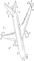
- aircraft 100 has number of airfoil structures 101.
- a "number of' items may be one or more items.
- a number of airfoil structures means one or more airfoil structures.
- number of airfoil structures 101 may include various types of airfoil structures.
- airfoil structures in number of airfoil structures 101 may be selected from at least one of a wingtip, a winglet, a wing, a horizontal stabilizer, a vertical stabilizer, an airbrake, a control surface, a rudder, a flap, a spoiler, an aileron, or a slat.
- the phrase "at least one of,” when used with a list of items, means different combinations of one or more of the listed items may be used and only one of the items in the list may be needed.
- the item may be a particular object, thing, or category.
- "at least one of' means any combination of items or number of items may be used from the list, but not all of the items in the list may be required.
- “at least one of item A, item B, and item C” may mean item A; item A and item B; item B; item A, item B, and item C; or item B and item C.
- “at least one of item A, item B, and item C” may mean, for example, without limitation, two of item A, one of item B, and ten of item C; four of item B and seven of item C; or some other suitable combination.
- number of airfoil structures 101 includes wing 102, wing 104, horizontal stabilizer 114, horizontal stabilizer 116, vertical stabilizer 118, and other suitable airfoil structures.
- wing 102 and wing 104 are attached to body 106.
- Engine 108 is attached to wing 102 and engine 110 is attached to wing 104.
- Body 106 has tail section 112.
- Horizontal stabilizer 114, horizontal stabilizer 116, and vertical stabilizer 118 are attached to body 106.
- wing 102 includes winglet 120.
- Winglet 120 may have number of blades 122. When winglet 120 has more than one blade, those blades may be arranged at an angle with respect to one another.
- winglet 120 is a bifurcated winglet. As depicted, a bifurcated winglet has two blades arranged at an angle relative to each other. Winglet 120 is attached to the tip of wing 102 in these illustrative examples.
- wing 104 includes winglet 124.
- Winglet 124 may include number of blades 126 arranged at an angle relative to one another.
- winglet 124 also is a bifurcated winglet. Winglet 124 is attached to the tip of wing 104 in these illustrative examples.
- Aircraft 100 is an example of an aircraft in which a one-piece bifurcated composite winglet may be implemented in accordance with an illustrative embodiment.
- the one-piece bifurcated composite winglet may be attached to a wing of aircraft 100 during manufacturing of aircraft 100, retro-fitted for use on aircraft 100, or added to aircraft 100 during various stages of the service life of aircraft 100.
- aircraft 100 in Figure 1 is not meant to imply physical or architectural limitations to the manner in which an illustrative configuration may be implemented.
- aircraft 100 is shown as a commercial aircraft, aircraft 100 also may be a military aircraft, a rotorcraft, a helicopter, an unmanned aerial vehicle, or any other suitable aircraft that may employ winglets.
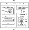
- aircraft manufacturing environment 200 includes aircraft 202 and tool 204.
- Aircraft 100 in Figure 1 is an example of one implementation for aircraft 202 shown in this figure.
- aircraft 202 comprises number of airfoil structures 206.
- Number of airfoil structures 101 in Figure 1 is an example of one implementation for number of airfoil structures 206 shown in this figure.
- An airfoil structure in number of airfoil structures 206 may take various forms.
- one of number of airfoil structures 206 may be selected from at least one of a wingtip, a wing, a horizontal stabilizer, a vertical stabilizer, an airbrake, a control surface, a rudder, a flap, a spoiler, an aileron, a slat, or other suitable types of airfoil structures.
- number of airfoil structures 206 includes composite winglet 208.
- Composite winglet 208 is an angled extension of a wingtip of aircraft 202.
- composite winglet 208 is a structure comprised of composite materials cured to form composite winglet 208.
- the angle, shape, and size of composite winglet 208 are unique to the application of aircraft 202.
- Winglet 120 and winglet 124 in Figure 1 may be examples of implementations for composite winglet 208 shown in block form in this figure.
- composite winglet 208 comprises number of blades 210.
- Composite winglet 208 is a bifurcated winglet and comprises two blades arranged at an angle relative to one another in this illustrative example.
- composite winglet 208 may have more or fewer blades, depending on the particular implementation.
- number of blades 210 in composite winglet 208 may include one blade, three blades, five blades, or another suitable number of blades, depending on the particular implementation.
- Composite winglet 208 may be comprised of a number of different types of material.
- composite winglet 208 may be comprised of a carbon fiber reinforced polymer, fiberglass, aramid fiber, nylon, and other suitable types of materials.
- composite winglet 208 is associated with wing 212 of aircraft 202.
- association is a physical association in the depicted examples.
- a first component such as composite winglet 208
- a second component such as wing 212
- the first component also may be connected to the second component using a third component.
- the first component may be considered to be associated with the second component by at least one of being formed as part of or as an extension of the second component.
- attachment system 214 may be configured to be placed inside of composite winglet 208 and attached to wing 212 of aircraft 202 using number of fasteners 216.
- attachment system 214 may be secured to composite winglet 208 using at least one of an adhesive, a weld, a bond, or some other suitable attachment mechanism.
- number of fasteners 216 may include various types of fasteners.
- number of fasteners 216 may include screws, clips, bolts, hinges, welds, flanges, anchors, rivets, pins, and other suitable types of fasteners.
- Number of fasteners 216 is configured to attach composite winglet 208 to wing 212 to provide a desired level of aerodynamic performance and a desired level of structural stability. This desired level of aerodynamic performance, desired level of structural stability, or both may be selected based on the type of aircraft selected for aircraft 202, the parameters of operation of aircraft 202, or a combination thereof.
- larger aircraft with greater wingspans may use more fasteners or stronger fasteners to offset higher speeds and wing loads.
- these larger aircraft may have larger dimensions for composite winglet 208 than smaller aircraft.
- composite winglet 208 for smaller aircraft configured to carry lighter loads and have shorter wingspans may have fewer of number of fasteners 216 attaching composite winglet 208 to wing 212 as compared to larger aircraft.
- composite winglet 208 is manufactured using tool 204.
- number of plies of composite material 218 is laid up on tool 204 to form composite winglet 208.
- a "ply" is a layer of fibrous composite material and may have resin infused within the layer.
- the ply may be referred to as prepreg.
- the ply does not have resin infused within it.
- resin may be infused within the material prior to or during curing, using commonly known impregnation methods.
- one of number of plies of composite material 218 may be selected from at least one of fabric, cloth, tape, tows, or other suitable configurations of composite material.
- curing system 220 is configured to cure number of plies of composite material 218 on tool 204 to form composite winglet 208.
- vacuum bag 222 is placed around tool 204 with number of plies of composite material 218.
- Vacuum 224 is then applied to tool 204 with number of plies of composite material 218 and cured using desired temperature 226 and desired pressure 228. After a period of time, composite winglet 208 may then be removed from tool 204 and attached to wing 212 of aircraft 202 in these illustrative examples.
- FIG. 3 an illustration of a block diagram of a composite winglet is depicted in accordance with an illustrative embodiment.
- a more-detailed illustration of composite winglet 208 with number of blades 210 from Figure 2 is shown.
- composite winglet 208 comprises first blade 300, second blade 302, and root region 304.
- First blade 300 may be upper blade 306 and includes first leading edge 308 and first trailing edge 310 in this illustrative example.
- first leading edge 308 is the portion of first blade 300 of composite winglet 208 that first contacts the air when aircraft 202 is in operation.
- first leading edge 308 of first blade 300 is the foremost edge of first blade 300.
- First trailing edge 310 of first blade 300 of composite winglet 208 is the rearmost edge of first blade 300, where airflow separated by first leading edge 308 rejoins.
- second blade 302 of composite winglet 208 includes second leading edge 314, and second trailing edge 316.
- Second blade 302 may take the form of lower blade 312 in this illustrative example.
- Second leading edge 314 of second blade 302 is the foremost edge of second blade 302, while second trailing edge 316 is the rearmost edge of second blade 302.
- Second blade 302 is positioned at an angle relative to first blade 300 in this depicted example.
- first blade 300 and second blade 302 may have a similar shape and similar dimensions. In one example, the dimensions of first blade 300 and second blade 302 may be substantially the same. In other illustrative examples, however, first blade 300 may have a different shape, dimensions, or both than second blade 302. For instance, first blade 300 may be longer than second blade 302.
- group of spars 318 is associated with number of blades 210.
- group of spars 318 may be positioned within number of blades 210.
- one of number of spars 318 is positioned within each of number of blades 210.
- more than one of number of spars 318 may be positioned within each of number of blades 210, depending on the particular implementation.
- root region 304 is co-cured with first blade 300 and second blade 302.
- root region 304 connects first blade 300 with second blade 302.
- co-curing refers to the act of curing one uncured composite part to another composite part or to a core material at substantially the same time.
- the core material may be selected from one of balsa, honeycomb, or foam core.
- root region 304 comprises channel 320.
- Channel 320 may be configured to receive attachment system 214 in Figure 2 .
- root region 304 may receive attachment system 214 in channel 320 of root region 304 and may be secured to attachment system 214 using number of fasteners 216 in Figure 2 .
- first blade 300, second blade 302, or both first blade 300 and second blade 302 may be associated with lightning strip 322.
- Lightning strip 322 is a lightning diverting device configured to protect composite winglet 208 from damage caused by an electromagnetic event, such as a lightning strike.
- lightning strip 322 is configured to dissipate electricity from an electromagnetic event.
- first trailing edge 310 of first blade 300 or second trailing edge 316 of second blade 302 is associated with lightning strip 322.
- Lightning strip 322 may extend along the entire surface of first trailing edge 310 or second trailing edge 316.
- lightning strip 322 is co-cured with composite winglet 208 when composite winglet 208 is cured.
- lightning strip 322 is co-cured with first blade 300, second blade 302, and root region 304 of composite winglet 208.
- lightning strip 322 may be connected to composite winglet 208 in some other suitable manner.
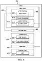
- FIG 4 an illustration of a block diagram of a tool for forming a composite winglet is depicted in accordance with an illustrative embodiment. In this depicted example, a more-detailed illustration of tool 204 from Figure 2 is shown.
- tool 204 includes first part 400, second part 402, and third part 404.
- First part 400, second part 402, and third part 404 are configured to receive number of plies of composite material 218 to form composite winglet 208 for aircraft 202 shown in block form in Figure 2 in this illustrative example.
- first part 400 includes upper portion 406 with first cavity 408 and lower portion 410 with second cavity 412.
- Upper portion 406 is associated with lower portion 410 in this illustrative example.
- upper portion 406 and lower portion 410 are welded together to form first part 400.
- Lower portion 410 is connected to upper portion 406 at transition region 414.
- lower portion 410 is arranged at an angle to upper portion 406.
- the angle may be selected based on a desired level of aerodynamic performance for composite winglet 208.
- first part 400 of tool 204 is configured to form an outboard skin of composite winglet 208.
- number of plies of composite material 218 is positioned in first part 400 of tool 204 to form the outboard skin of composite winglet 208 once cured.
- a number of plies of composite material are laid up on the upper portion 406 of first part 400 to form the outboard skin of upper blade 306 of composite winglet 208 from Figure 3 , while lower portion 410 of first part 400 is configured to form the outboard skin of lower blade 312 of composite winglet 208 from Figure 3 .
- an "outboard skin” is the skin of composite winglet 208 that faces outwardly away from the body of the aircraft.
- Transition region 414 forms the outboard portion of root region 304.
- second part 402 is configured to be placed over first cavity 408 of upper portion 406 of first part 400 of tool 204.
- third part 404 is configured to be placed over second cavity 412 of lower portion 410 of first part 400 of tool 204.
- a number of plies of composite material may be laid up on second part 402 to form an inboard skin of first blade 300, and third part 404 may form an inboard skin of second blade 302 in this illustrative example.
- an "inboard skin” is the skin of composite winglet 208 that faces inwardly toward the body of the aircraft.
- tool 204 may be comprised of a number of different types of material.
- tool 204 may be comprised of one or more materials selected from at least one of a metal, a metal alloy, wood, foam, steel, poly(methyl methacrylate), aluminum, nickel, an aluminum-nickel alloy, or some other suitable material.
- tool 204 may be comprised of a material with a coefficient of thermal expansion that is similar to that of the material selected for number of plies of composite material 218. Moreover, depending on the curing conditions and the heat and pressure applied to tool 204, various materials may be selected to form an illustrative embodiment in a desired manner. Tool 204 may be fabricated using well-known tool fabrication techniques.
- tool 204 comprises leading edge 416 and trailing edge 418 opposite leading edge 416.
- leading edge 416 of tool 204 corresponds to first leading edge 308 of first blade 300 and second leading edge 314 of second blade 302 of composite winglet 208 in Figure 3 .
- trailing edge 418 of tool 204 corresponds to first trailing edge 310 of first blade 300 and second trailing edge 316 of second blade 302 of composite winglet 208 in Figure 3 .
- Parting line 420 is arranged along leading edge 416 of tool 204 in this illustrative example. Parting line 420 is the portion of tool 204 where second part 402 and third part 404 may be attached to first part 400 of tool 204.
- At least one of second part 402 or third part 404 may be attached to upper portion 406 and lower portion 410 of first part 400, respectively, using fastener system 422 in this illustrative example.
- Fastener system 422 may include at least one of nuts, bolts, screws, clips, anchors, adhesive, or other suitable types of fasteners.
- tool 204 also comprises gap 424 in trailing edge 418 of tool 204.
- Gap 424 is configured to form a thin trailing edge for composite winglet 208.
- a number of additional gaps also may be present in tool 204 in other illustrative examples.
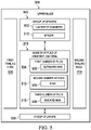
- FIG. 5 an illustration of a block diagram of an upper blade of a composite winglet is depicted in accordance with an illustrative embodiment.
- a more-detailed illustration of upper blade 306 of composite winglet 208 from Figure 3 is shown.
- upper blade 306 is formed using number of plies of composite material 218 and group of spacers 500.
- Group of spacers 500 forms number of chambers 502 within the interior of upper blade 306.
- one of group of spacers 500 is selected from at least one of a caul plate, a bag, a bag carrier, a mandrel, or some other suitable spacer.
- Group of spacers 500 may be comprised of a material selected from one of aluminum, foam, cork, a water-soluble powder, carbon, and other suitable materials. These materials may be selected to be flexible such that group of spacers 500 may be extracted from composite winglet 208 after curing. In some cases, the group of spacers 500 may have to be segmented in addition to being flexible, in order to be extracted through constrictions in the cured part.
- Group of spacers 500 may be positioned within tool 204 to form number of chambers 502 within the interior of upper blade 306 when upper blade 306 is cured. In some illustrative examples, group of spacers 500 are inflated prior to curing of composite winglet 208 to exert pressure on the inner skin of upper blade 306.
- first number of plies 504 is laid up on tool 204 to form outboard skin 506 of upper blade 306 .
- first number of plies 504 may include two plies of carbon fiber reinforced polymer material. In other illustrative examples, first number of plies 504 may include more or fewer than two plies.
- Group of layups 508 are then placed on tool 204 .
- Group of layups 508 comprises second number of plies 510 covering spacer 512 to form spar 514 to provide support in the interior of upper blade 306.
- One or more additional spacers in group of spacers 500 may be positioned in tool 204 to form number of chambers 502. Third number of plies 516 is then positioned over spar 514 and group of spacers 500 to form inboard skin 518 of upper blade 306.
- Second number of plies 510 and third number of plies 516 may also comprise two plies in some illustrative examples. Other suitable configurations of plies may be implemented in other illustrative examples.
- lower blade 312 also may include the same components.
- lower blade 312 includes components in addition to or in place of the ones illustrated for upper blade 306.
- composite winglet 208 and the components within composite winglet 208 in Figures 2-5 are not meant to imply physical or architectural limitations to the manner in which an illustrative embodiment may be implemented. Other components in addition to or in place of the ones illustrated may be used. Some components may be optional. Also, the blocks are presented to illustrate some functional components. One or more of these blocks may be combined, divided, or combined and divided into different blocks when implemented in an illustrative embodiment.
- composite winglet 208 may have only one blade arranged at an angle relative to a wing of the aircraft.
- the blade may be angled upward from the wing of the aircraft.
- tool 204 may be used to form another type of airfoil structure, such as a horizontal stabilizer or a vertical stabilizer.
- another type of airfoil structure such as a horizontal stabilizer or a vertical stabilizer.
- the number of spacers and configurations of plies of composite material may be different than described above.
- composite winglet 600 is an example of one implementation for composite winglet 208 shown in block form in Figures 2-3 .
- Composite winglet 600 is a one-piece bifurcated winglet in this illustrative example. In other words, the components within composite winglet 600 have been co-cured to form a single part. As a result, fasteners or other components are not needed to connect one portion of composite winglet 600 to other portions of composite winglet 600.
- Composite winglet 600 has a smooth surface in this illustrative example.
- composite winglet 600 comprises upper blade 602, lower blade 604, and root region 606.
- Upper blade 602, lower blade 604, and root region 606 are examples of implementations for first blade 300, second blade 302, and root region 304 in Figure 3 , respectively.
- upper blade 602 is longer than lower blade 604.
- upper blade 602 and lower blade 604 may be the same length.
- lower blade 604 may be longer than upper blade 602.
- upper blade 602 includes leading edge 608 and trailing edge 610, while lower blade 604 includes leading edge 612 and trailing edge 614.
- Upper blade 602 has outboard skin 616, inboard skin 618, and opening 620.
- lower blade 604 has outboard skin 622, inboard skin 624, and opening 626.
- Opening 620 and opening 626 may be configured to receive caps in this illustrative example.
- the caps may seal opening 620 and opening 626.
- opening 620 and opening 626 may be used to remove group of spacers 500 in Figure 5 from the interior of composite winglet 208 before the caps are placed on opening 620 and opening 626.
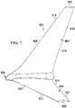
- FIG 7 an illustration of a side view of a composite winglet is depicted in accordance with an illustrative embodiment.
- composite winglet 600 is shown in the direction of view lines 7-7 in Figure 6 .
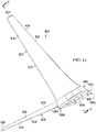
- FIG. 8 an illustration of a front view of a composite winglet is depicted in accordance with an illustrative embodiment.
- composite winglet 600 is shown in the direction of view lines 8-8 in Figure 6 .
- upper blade 602 and lower blade 604 are positioned at angle 800 with respect to one another.
- Angle 800 may be selected to achieve a desired level of aerodynamic performance for composite winglet 600.
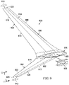
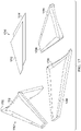
- FIG. 9 an illustration of a perspective view of a composite winglet is depicted in accordance with an illustrative embodiment.
- composite winglet 600 is shown in the direction of view lines 9-9 in Figure 6 .
- spar 900 and spar 902 are shown in phantom in this figure.
- Spar 900 is configured to provide support for upper blade 602, while spar 902 is configured to provide support for lower blade 604.
- Spar 900 and spar 902 may be examples of implementations for spar 514 in Figure 5 .
- root region 606 of composite winglet 600 comprises channel 906 configured to receive attachment system 908 to attach composite winglet 600 to a wing of an aircraft.
- Cap 910 and cap 912 are also present in this illustrative example.
- Cap 910 is configured to seal opening 620 in upper blade 602 after group of spacers 500 shown in block form in Figure 5 is removed from upper blade 602. Cap 910 seals opening 620 in upper blade 602 such that a fluid does not pass between the interface of cap 910 and the inner skin of upper blade 602. This fluid may be air, water, or some other type of fluid in the environment around composite winglet 600.
- cap 912 is configured to seal opening 626 in lower blade 604 after group of spacers 500 is removed from lower blade 604. Cap 912 seals opening 626 in lower blade 604 such that fluid does not pass between the interface of cap 912 and the inner skin of lower blade 604.
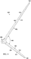
- FIG. 10 an illustration of a root region is depicted in accordance with an illustrative embodiment. In this depicted example, a closer view of root region 606 is shown.
- root region 606 has shape 1000. Shape 1000 is configured to provide a desired level of aerodynamic performance for composite winglet 600. Root region 606 has leading edge 1002 and trailing edge 1004. Leading edge 1002 is a location where leading edge 608 of upper blade 602 and leading edge 612 of lower blade 604 meet. In a similar fashion, trailing edge 1004 is a location where trailing edge 610 of upper blade 602 and trailing edge 614 of lower blade 604 meet.
- leading edge 1002 of root region 606 has curved shape 1006, while trailing edge 1004 of root region 606 has pointed shape 1008.
- shape of leading edge 1002 and trailing edge 1004 may be different than shown in this figure, depending on the functionality of composite winglet 600.
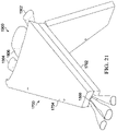
- FIG. 11 an illustration of a back view of a composite winglet is depicted in accordance with an illustrative embodiment.
- composite winglet 600 is shown in the direction of view lines 11-11 in Figure 9 .
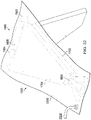
- FIG. 12 an illustration of a cross-sectional view of a composite winglet is depicted in accordance with an illustrative embodiment.
- a cross-sectional view of composite winglet 600 is shown taken along lines 12-12 in Figure 11 .
- composite winglet 600 includes number of chambers 1200.
- Number of chambers 1200 is an example of one implementation for number of chambers 502 shown in block form in Figure 5 .
- upper blade 602 includes chamber 1202 and lower blade 604 includes chamber 1204.
- Chamber 1202 and chamber 1204 may be formed using spacers during curing of composite winglet 600.
- tool 1300 is an example of one implementation for tool 204 shown in block form in Figure 2 .
- tool 1300 includes first part 1302, second part 1304, and third part 1306.
- Tool 1300 has leading edge 1308 and trailing edge 1310 in this illustrative example.
- first part 1302 of tool 1300 includes upper portion 1312 and lower portion 1314.
- Tool 1300 includes a number of openings 1316 in leading edge 1308 of tool 1300.
- the number of openings 1316 is configured to receive a fastener system (not shown in this view) to seal tool 1300.
- gap 1318 is also present in tool 1300.
- Gap 1318 is used to form the shape of a root region of a composite winglet in this depicted example.
- gap 1318 may form shape 1000 of root region 606 shown in Figure 10 .
- gaps may be present in tool 1300.
- gaps may be present in at least one of tip 1320 or tip 1322 of tool 1300 in these illustrative examples.
- Tool 1300 may be used to form composite winglet 600 shown in Figure 6 .
- upper portion 1312 of first part 1302 and second part 1304 may be used to form upper blade 602 of composite winglet 600
- lower portion 1314 of first part 1302 and third part 1306 may be configured to form lower blade 604 of composite winglet 600.
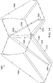
- FIG. 14 an illustration of an exploded view of a tool for forming a composite winglet is depicted in accordance with an illustrative embodiment.
- an exploded view of tool 1300 from Figure 13 is shown.
- Transition region 1400 is a region where upper portion 1312 and lower portion 1314 are welded together in this illustrative example.
- FIG. 15 an illustration of a tool for forming a composite winglet is depicted in accordance with an illustrative embodiment.
- tool 1300 is shown in the direction of view lines 15-15 in Figure 13 .
- tool 1300 has parting line 1500 in leading edge 1308.
- Parting line 1500 is the portion of tool 1300 where second part 1304 and third part 1306 may be attached to first part 1302 of tool 1300.
- Gap 1502 in tip 1320 of tool 1300 and gap 1504 in tip 1322 of tool 1300 may be seen more clearly.
- Gap 1502 and gap 1504 may be configured to form opening 620 and opening 626, respectively, in composite winglet 600 in Figure 6 .
- upper portion 1312 of first part 1302 and second part 1304 are arranged at angle 1506 relative to lower portion 1314 of first part 1302 and third part 1306.
- Angle 1506 may be selected to form a desired angle for the composite winglet.
- angle 1506 may be selected to form angle 800 for composite winglet 600 as shown in Figure 8 .
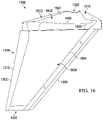
- FIG 16 an illustration of a first part of a tool for forming an outboard skin of a composite winglet is depicted in accordance with an illustrative embodiment. In this depicted example, a more-detailed view of first part 1302 is shown.
- cavity 1606 is used to form the shape of a lower blade of a composite winglet.
- cavity 1606 may form lower blade 604 of composite winglet 600 in Figure 6 .
- inner surface 1600 of upper portion 1312 of first part 1302 has cavity 1602 used to form the shape of an upper blade of a composite winglet.
- cavity 1602 may form upper blade 602 of composite winglet 600 in Figure 6 .
- lip 1608 is seen in upper portion 1312.
- Lip 1608 in upper portion 1312 of first part 1302 of tool 1300 is configured to form a leading edge of an upper blade of a winglet.
- lip 1608 may be configured to form leading edge 608 of upper blade 602 of composite winglet 600 in Figure 6 .
- Lower portion 1314 also includes a lip (not shown in this view) configured to form a leading edge of a lower blade of a composite winglet.
- the lip may form leading edge 612 of lower blade 604 of composite winglet 600 in Figure 6 .
- the shape of inner surface 1600 and inner surface 1604 may be selected to form a desired shape of the outboard skin of a composite winglet.
- the inner surface of second part 1304 and third part 1306 also may be selected to form a desired shape of the inboard skin of a composite winglet.
- the composite winglet may be designed to have a smooth surface, which increases the aerodynamic performance and the strength of the composite winglet.
- Figures 17-22 illustrate one example of a process used for forming a composite winglet.
- Figures 17-22 show different steps in a process for forming composite winglet 2400 shown in Figure 24 .
- FIG. 17 an illustration of a tool for forming a composite winglet is depicted in accordance with an illustrative embodiment.
- tool 1700 with first part 1702, second part 1704, and third part 1706 is shown.
- tool 1700 may be coated with coating material 1708.
- Coating material 1708 may be a mold release agent that is configured to coat the inner surfaces of tool 1700 such that the composite winglet may be more easily separated from tool 1700 after curing of the composite winglet.
- number of plies of composite material 1710 may be cut and placed into first part 1702 of tool 1700.
- Number of plies of composite material 1710 form the outboard skin of composite winglet 2400 in Figure 24 .
- first number of plies 1712 forms the outboard skin of an upper blade of composite winglet 2400
- second number of plies 1714 forms the outboard skin of a lower blade of composite winglet 2400 in these illustrative examples.
- FIG 18 an illustration of a tool with a group of layups is depicted in accordance with an illustrative embodiment.
- layup 1800 has been positioned in tool 1700.
- layup 1800 may be comprised of third number of plies 1802 of composite material wrapped around spacer 1804.
- spacer 1804 is made of a bag carrier (not shown) positioned within bag 1806.
- layup 1800 may be formed in another manner, depending on the particular implementation.
- FIG. 19 an illustration of a tool with a number of spacers is depicted in accordance with an illustrative embodiment.
- number of spacers 1900 is positioned in tool 1700.
- number of spacers 1900 includes bag 1902 and bag 1904. Bag 1902, bag 1904, and bag 1806 are configured to be inflated to form chambers within composite winglet 2400 in Figure 24 in these illustrative examples. In other illustrative examples, number of spacers 1900 may include different types of spacers other than bags, depending on the functionality involved.
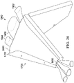
- FIG 20 an illustration of a tool for forming a composite winglet is depicted in accordance with an illustrative embodiment.
- fourth number of plies 2000 of composite material has been positioned on top of layup 1800.
- Fourth number of plies 2000 forms the inboard skin of the upper blade of composite winglet 2400 in Figure 24 .
- FIG 21 another illustration of a tool for forming a composite winglet is depicted in accordance with an illustrative embodiment.
- second part 1704 of tool 1700 has been positioned over first number of plies 1712 (not seen in this view), layup 1800, and third number of plies 2000 (not seen in this view).
- second part 1704 may be attached to first part 1702 of tool 1700 using a fastener system. In some cases, second part 1704 may be attached to first part 1702 of tool 1700 using a fastener system and then further sealed with tape.
- FIG. 22 yet another illustration of a tool for forming a composite winglet is depicted in accordance with an illustrative embodiment.
- vacuum bag 2200 has been placed over tool 1700.
- vacuum bag 2200 may be sealed and attached to hose 2222.
- Hose 2222 is connected to a vacuum source (not shown) to pull a vacuum on tool 1700 to cure composite winglet 2400 in Figure 24 .
- Tool 1700 is exposed to a desired temperature and pressure during the curing process.
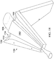
- FIG 23 an illustration of a lightning strip co-cured with a composite winglet is depicted in accordance with and illustrative embodiment.
- lightning strip 2300 has been co-cured a composite winglet.
- lightning strip 2300 has been co-cured with composite winglet 2400.
- lightning strip 2300 may be added to the composite winglet during one of the steps described with reference to Figures 17-21 , prior to placing vacuum bag 2200 over tool 1700 and curing the composite winglet.
- lightning strip 2300 is configured to dissipate electricity and prevent damage to the composite winglet.
- Lightning strip 2300 has first portion 2302 and second portion 2304 attached to number of plies of composite material 2306.
- Lightning strip 2300 is attached to the composite winglet on the trailing edge of the composite winglet in this illustrative example. In other illustrative examples, lightning strip 2300 may be attached to another portion of the composite winglet or may have a different shape, depending on the particular implementation.
- the illustrative examples in Figures 17-23 are shown with reference to forming an upper blade of a composite winglet, the lower blade of the composite winglet may be formed in a similar manner and at the same time as the upper blade. In some illustrative examples, it may be desirable to form the lower blade and upper blade at different times.
- Figures 17-23 only show some of the operations or stages for forming a composite winglet. Other components, operations, and stages may be present in addition to in place of the ones depicted in Figures 17-23 .
- a release layer may be used in addition or in place of coating material 1708 on tool 1700.
- a number of additional spars may be positioned in tool 1700.
- tool 1700 or a portion of tool 1700 and the process described with reference to any one of Figures 17-23 may be used to rework composite winglet 2400 rather than manufacture composite winglet 2400 in Figure 24 .
- FIG 24 an illustration of a composite winglet with a lightning strip is depicted in accordance with an illustrative embodiment.
- composite winglet 2400 with lightning strip 2300 is formed using the process described with reference to Figures 17-23 .
- composite winglet 2400 includes upper blade 2402, lower blade 2404, and root region 2406. Number of spacers 1900 and spacer 1804 in Figure 19 and Figure 18 , respectively, are still present within composite winglet 2400 at this time.
- FIG. 25 a cross-sectional view of a composite winglet is depicted in accordance with an illustrative embodiment.
- a cross-sectional view of composite winglet 2400 taken along lines 25-25 in Figure 24 is shown.
- bag 1806 is seen in upper blade 2402 of composite winglet 2400, while bag 2500 is shown in lower blade 2404 of composite winglet 2400.
- Bag 2502 and bag 2504 form a channel in root region 2406 of composite winglet 2400.
- a number of additional spacers may be positioned within composite winglet 2400 to provide additional support or pressure during curing.
- caul plates may be positioned against the side surfaces of layup 1800 in Figures 18-22 to form straighter spars for composite winglet 2400.
- caul plates may be used to form straighter spars within root region 2406 of composite winglet 2400. These additional spacers may be removed with the bags after curing of composite winglet 2400.
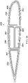
- FIG 26 an illustration of a root region of a composite winglet is depicted in accordance with an illustrative embodiment.
- a more-detailed view of root region 2406 of composite winglet 2400 is seen in the direction of view lines 26-26 in Figure 24 .
- bag 2502, bag 2504, bag 2600 and bag 2602 form channels in root region 2406 of composite winglet 2400.
- bag 2600 forms the leading edge of root region 2406
- bag 2602 forms trailing edge of root region 2406.
- composite winglet 2400 After curing of composite winglet 2400, all bags and other spacers may be removed from the gaps in composite winglet 2400. Composite winglet 2400 may then be trimmed. In other illustrative examples, composite winglet 2400 may be trimmed prior to removing the bags and other spacers.
- FIG. 27 an illustration of a composite winglet with an attachment system installed within the composite winglet is depicted in accordance with an illustrative embodiment.
- attachment system 2700 has been installed within root region 2406 of composite winglet 2400.
- number of fasteners 2702 is used to secure attachment system 2700 to root region 2406 of composite winglet 2400.
- number of fasteners 2702 may secure attachment system 2700 to at least one of support 2704, support 2706, upper surface 2708, or lower surface 2710 of root region 2406 of composite winglet 2400.
- FIG. 28 an illustration of a cross-sectional view of a composite winglet with an attachment system installed within the composite winglet is depicted in accordance with an illustrative embodiment.
- a cross-sectional view of composite winglet 2400 with attachment system 2700 taken along the lines 28-28 in Figure 27 is shown.
- attachment system 2700 does not extend within upper blade 2402 or lower blade 2404 of composite winglet 2400.
- upper blade 2402 and lower blade 2404 may be thinner than with some currently used winglets that need an attachment system that extends within the upper and lower blades of the winglet.
- Figures 6-28 may be illustrative examples of how components shown in block form in Figures 2-5 can be implemented as physical structures. Additionally, some of the components in Figures 6-28 may be combined with components in Figures 2-5 , used with components in Figures 2-5 , or a combination of the two.
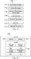
- FIG. 29 an illustration of a flowchart of a process for forming a composite winglet is depicted in accordance with an illustrative embodiment.
- the process illustrated in Figure 29 may be implemented in aircraft manufacturing environment 200 in Figure 2 .
- One or more of the different operations may be implemented using one or more components in aircraft manufacturing environment 200 for aircraft 202 in Figure 2 .
- the process begins by laying up a number of plies of composite material on a tool (operation 2900 ).
- the tool comprises a first part including and upper portion with a first cavity and a lower portion with a second cavity.
- the lower portion is positioned at an angle to the upper portion and connected to the upper portion at a transition region.
- the tool further comprises a second part configured to be placed over the first cavity of the upper portion and a third part configured to be placed over the second cavity of the lower portion.
- a group of spacers is positioned within the first cavity and the second cavity of the tool (operation 2902 ).
- the group of spacers is configured to form a number of chambers within the composite winglet.
- a second part is placed over the first cavity and a third part is placed over the second cavity (operation 2904 ). Placing the second part over the first cavity and the third part over the second cavity seals the tool.
- the number of plies of composite material is then cured to form a composite winglet for an aircraft as a single part (operation 2906 ), with the process terminating thereafter.
- a vacuum may be applied to the number of plies of composite material and the tool.
- the number of plies of composite material also may be heated to a desired temperature.
- curing may occur in a different manner.
- the number of plies of composite material may not be pre-impregnated with resin.
- resin may need to be infused into the number of plies of composite material prior to or during curing.
- the composite winglet may be formed using techniques such as a room temperature cure, resin transfer molding (RTM), or other suitable curing techniques.
- a number of radius fillers may be placed at a co-cured joint between at least one of the outboard skin or the inboard skin of the composite winglet or the spar.
- a lightning strip may be positioned within the tool prior to curing the number of plies of composite material such that the number of plies of composite material and the lightning strip are co-cured.
- FIG. 30 an illustration of a flowchart of a process for laying up a number of plies of composite material is depicted in accordance with an illustrative embodiment.
- the process described with reference to Figure 30 may be implemented in operation 2900 in Figure 29 .
- the process begins by laying up a first number of plies on the tool to form an outboard skin of the composite winglet (operation 3000 ).
- a group of layups is placed on the tool (operation 3002 ).
- the group of layups includes a spacer covered with a second number of plies to form a spar.
- a group of spacers is placed within the tool (operation 3004 ).
- the process then lays up a third number of plies over the group of layups and the group of spacers to form an inboard skin of the composite winglet (operation 3006 ), with the process terminating thereafter.
- each block in the flowcharts or block diagrams may represent a module, a segment, a function, and or a portion of an operation or step.
- the function or functions noted in the blocks may occur out of the order noted in the figures.
- two blocks shown in succession may be executed substantially concurrently, or the blocks may sometimes be performed in the reverse order, depending upon the functionality involved.
- other blocks may be added in addition to the illustrated blocks in a flowchart or block diagram.
- aircraft manufacturing and service method 3100 may be described in the context of aircraft manufacturing and service method 3100 as shown in Figure 31 and aircraft 3200 as shown in Figure 32 .
- Figure 31 an illustration of a block diagram of an aircraft manufacturing and service method is depicted in accordance with an illustrative embodiment.
- aircraft manufacturing and service method 3100 may include specification and design 3102 of aircraft 3200 in Figure 32 and material procurement 3104.
- aircraft 3200 in Figure 32 During production, component and subassembly manufacturing 3106 and system integration 3108 of aircraft 3200 in Figure 32 takes place. Thereafter, aircraft 3200 in Figure 32 may go through certification and delivery 3110 in order to be placed in service 3112. While in service 3112 by a customer, aircraft 3200 in Figure 32 is scheduled for routine maintenance and service 3114, which may include modification, reconfiguration, refurbishment, and other maintenance or service.
- Each of the processes of aircraft manufacturing and service method 3100 may be performed or carried out by at least one of a system integrator, a third party, or an operator.
- the operator may be a customer.
- a system integrator may include, without limitation, any number of aircraft manufacturers and major-system subcontractors
- a third party may include, without limitation, any number of vendors, subcontractors, and suppliers
- an operator may be an airline, a leasing company, a military entity, a service organization, and so on.
- aircraft 3200 is produced by aircraft manufacturing and service method 3100 in Figure 31 and may include airframe 3202 with plurality of systems 3204 and interior 3206.
- systems 3204 include one or more of propulsion system 3208, electrical system 3210, hydraulic system 3212, and environmental system 3214. Any number of other systems may be included.
- propulsion system 3208 one or more of propulsion system 3208, electrical system 3210, hydraulic system 3212, and environmental system 3214. Any number of other systems may be included.
- an aerospace example is shown, different illustrative embodiments may be applied to other industries, such as the automotive industry.
- Apparatuses and methods embodied herein may be employed during at least one of the stages of aircraft manufacturing and service method 3100 in Figure 31 .
- components or subassemblies produced in component and subassembly manufacturing 3106 in Figure 31 may be fabricated or manufactured in a manner similar to components or subassemblies produced while aircraft 3200 is in service 3112 in Figure 31 .
- one or more apparatus embodiments, method embodiments, or a combination thereof may be utilized during production stages, such as component and subassembly manufacturing 3106 and system integration 3108 in Figure 31 .
- One or more apparatus embodiments, method embodiments, or a combination thereof may be utilized while aircraft 3200 is in service 3112 and/or during maintenance and service 3114 in Figure 31 .
- the use of a number of the different illustrative embodiments may substantially expedite the assembly of and/or reduce the cost of aircraft 3200.
- composite winglet 208 from Figure 2 may be formed and installed during any one of the stages of aircraft manufacturing and service method 3100.
- composite winglet 208 may be formed during subassembly manufacturing 3106.
- composite winglet 208 may be installed during system integration 3108, routine maintenance and service 3114, or some other stage of aircraft manufacturing and service method 3100.
- Composite winglet 208 comprises first blade 300, second blade 302, and root region 304.
- First blade 300 includes first leading edge 308 and first trailing edge 310.
- Second blade 302 includes second leading edge 314 and second trailing edge 316.
- Second blade 302 is positioned at an angle to first blade 300.
- Root region 304 is co-cured with first blade 300 and second blade 302 to form composite winglet 208.
- Root region 304 is configured to receive attachment system 214 for attaching composite winglet 208 to wing 212 of aircraft 202.
- a composite winglet may be formed more quickly than using currently available systems. For instance, instead of manufacturing many parts and assembling them together, a composite winglet may be formed using a single tool to create a single composite piece. Forming the composite winglet in one piece decreases the time and cost of manufacturing and assembling winglets for aircraft. Additionally, forming the winglet with composite materials decreases the weight of the winglet for aircraft.
- a desired level of structural integrity may be achieved. For example, because fewer fasteners are used to attach the root region of the composite winglet to the wing of an aircraft, the composite material of the blades of the composite winglet maintain their strength. Moreover, the smooth surface of the blades results in increased aerodynamic performance as compared to some currently used systems.
- composite winglets formed with the use of an illustrative embodiment may accommodate thinner blades than some currently manufactured winglets. For instance, because the attachment system for the composite winglet only extends within the root region of the composite winglet, as opposed to the blades, the blades of the winglet may be made thinner and more aerodynamic than before. As a result, fuel efficiency for the aircraft may be increased.
- the illustrative embodiments also provide a novel implementation for forming composite structures and extracting spacers from these composite structures.
- materials selected for spacers used to form chambers within the composite structure are selected to be flexible and to be extracted from the composite structure without causing undesired inconsistencies in the composite structure.
- foam may be used for bag carriers within the composite winglet. These foam bag carriers may be easily extracted from the composite winglet without resulting in undesired inconsistencies that increase the manufacturing or maintenance time of the aircraft.
- a complex geometry for a composite winglet may be formed.
- two blades joint at a root region having a smooth skin provides a desired level of aerodynamic performance, decreased weight, and ease of assembly on a wing of the aircraft.
Description
- The present disclosure relates generally to an aircraft and, in particular, to composite structures for the aircraft. Still more particularly, the present disclosure relates to a method and apparatus for a one-piece composite bifurcated winglet for the aircraft.
- Aircraft are being designed and manufactured with greater and greater percentages of composite materials. Composite materials are used in aircraft to decrease the weight of the aircraft. This decreased weight improves performance characteristics such as payload capacities and fuel efficiencies. Further, composite materials provide longer service life for various components in an aircraft.
- Composite materials are tough, lightweight materials created by combining two or more functional components. For example, a composite material may include reinforcing fibers bound in a polymer resin matrix. The fibers may be unidirectional or may take the form of a woven cloth or fabric. The fibers and resins are arranged and cured to form a composite material.
- In manufacturing composite structures, layers of composite material are typically laid up on a tool. The layers may be comprised of fibers in sheets. These sheets may take the form of fabrics, tape, tows, or other suitable forms. In some cases, resin may be pre-impregnated into the sheets. These types of sheets are commonly referred to as prepreg.
- The different layers of prepreg may be laid up in different orientations and different numbers of layers may be used depending on the thickness of the composite structure being manufactured. These layers may be laid up by hand or by using automated lamination equipment such as a tape laminating machine or a fiber placement system.
- After the different layers of composite material have been laid up on the tool, the layers of composite material may be consolidated and cured upon exposure to temperature and pressure, thus forming the final composite structure. Thereafter, the composite structure may be inspected to determine whether inconsistencies are present, and, if no inconsistencies are identified, the composite structure may be put in service.
- Composite materials are used for winglets on an aircraft. The use of composite materials in winglets may reduce the weight of the aircraft as compared to using metal materials for the winglets.
- In this illustrative example, a "winglet" refers to an angled extension of a wingtip of the aircraft. The angle, shape, and size of a winglet are unique to the application of the aircraft. Some winglets may be bifurcated winglets. In this illustrative example, a "bifurcated winglet" is a winglet that has two blades arranged at an angle relative to one another.
-
US 2012/0312928 discloses a split winglet having a first generally upward projecting wing end, and a second generally downward projecting wing end. The second generally downward projecting wing end may be integrally formed with the first generally upward projecting wing end to form a winglet assembly or may be separately attached onto an existing upwardly curved winglet. - The invention can involve a composite winglet for an aircraft that may include a first blade including a first leading edge and a first trailing edge; a second blade including a second leading edge and a second trailing edge, wherein the second blade is positioned at an angle to the first blade; and a root region co-cured with the first blade and the second blade to form the composite winglet, wherein the root region is configured to receive an attachment system for attaching the composite winglet to a wing of the aircraft. The first blade may be an upper blade of the composite winglet and the second blade is a lower blade of the composite winglet. The root region may receive the attachment system in a channel of the root region and is secured to the attachment system using at least one of an adhesive, a weld, a bond, or a number of fasteners. The at least one of the first trailing edge or the second trailing edge may be physically associated with a lightning strip. The lightning strip may be co-cured with the composite winglet when the composite winglet is cured. The composite winglet may include a carbon fiber reinforced polymer, fiberglass, aramid fiber, and nylon.
- The invention can involve the use of a tool for forming a composite winglet that may include a first part including an upper portion with a first cavity and a lower portion with a second cavity, wherein the lower portion is arranged at an angle to the upper portion and connected to the upper portion at a transition region; a second part configured to be placed over the first cavity of the upper portion; and a third part configured to be placed over the second cavity of the lower portion, wherein the first part, the second part, and the third part are configured to receive a number of plies of composite material to form a composite winglet for an aircraft. The upper portion of the first part is configured to form an upper blade of the composite winglet and the lower portion of the first part is configured to form a lower blade of the composite winglet. The tool is comprised of a material selected from at least one of a metal, a metal alloy, wood, foam, steel, poly(methyl methacrylate), aluminum, nickel, or an aluminum-nickel alloy. The tool may include a leading edge and a trailing edge opposite the leading edge, wherein a parting line is positioned along the leading edge of the tool. The tool may also include a gap in the trailing edge of the tool.
- The invention can involve a method for forming a composite winglet for an aircraft that may include laying up a number of plies of composite material on a tool, wherein the tool comprises a first part including an upper portion with a first cavity and a lower portion with a second cavity, wherein the lower portion is positioned at an angle to the upper portion and connected to the upper portion at a transition region; a second part configured to be placed over the first cavity of the upper portion; and a third part configured to be placed over the second cavity of the lower portion; positioning a group of spacers within the first cavity and the second cavity of the tool, wherein the group of spacers are configured to form a number of chambers within the composite winglet; placing the second part over the first cavity and the third part over the second cavity; and curing the number of plies of composite material to form the composite winglet for the aircraft as a single part. The curing the number of plies of composite material for the aircraft as the single part may include applying a vacuum to the number of plies of composite material and the tool; and heating the number of plies of composite material and the tool to a desired temperature. The placing the second part over the first cavity and placing the third part over the second cavity may be configured to seal the tool. The group of spacers may be selected from at least one of a caul plate, a bag, a bag carrier, or a mandrel. The laying up of the number of plies of composite material on the tool may include laying up a first number of plies on the tool to form an outboard skin of the composite winglet; placing a group of layups on the tool, the group of layups including a spacer covered with a second number of plies to form a spar; placing the group of spacers within the tool; and laying up a third number of plies over the group of layups and the group of spacers to form an inboard skin of the composite winglet. The method may also include placing a number of radius fillers between at least one of the outboard skin or the inboard skin of the composite winglet and the spar. The number of plies of composite material may include a carbon fiber reinforced polymer, fiberglass, aramid fiber, and nylon. The first number of plies and the second number of plies may each may include of two plies of carbon fiber reinforced polymer material. The method may also include positioning a lightning strip within the tool prior to curing the number of plies of composite material such that the number of plies of composite material and the lightning strip are co-cured.
- In some cases, however, winglets may be more complicated and costly to manufacture than desired. Moreover, as the complexity of composite winglets increases, the assembly and maintenance time for an aircraft also increases. Therefore, it would be desirable to have a method and apparatus that take into account at least some of the issues discussed above, as well as other possible issues.
- According to the present invention there is provided a composite winglet for an aircraft and a method for forming a composite winglet for an aircraft as claimed in the appended claims. A composite winglet for an aircraft comprises a first blade, a second blade, and a root region. The first blade includes a first leading edge and a first trailing edge. The second blade includes a second leading edge and a second trailing edge. The second blade is positioned at an angle to the first blade. The root region is co-cured with the first blade and the second blade to form the composite winglet. The root region is configured to receive an attachment system for attaching the composite winglet to a wing of the aircraft.
- A tool for forming a composite winglet comprises a first part, a second part, and a third part. The first part includes an upper portion with a first cavity and a lower portion with a second cavity. The lower portion is arranged at an angle to the upper portion and connected to the upper portion at a transition region. The second part is configured to be placed over the first cavity of the upper portion. The third part is configured to be placed over the second cavity of the lower portion. The first part, the second part, and the third part are configured to receive a number of plies of composite material to form a composite winglet for an aircraft.
A method for forming a composite winglet for an aircraft is provided. The method comprises: A. laying up a number of plies of composite material on a tool, wherein the tool comprises a first part including an upper portion with a first cavity and a lower portion with a second cavity wherein the first cavity is used to form the shape of an upper blade of the winglet, and the second cavity is used to form the shape of a lower blade of the winglet, wherein the lower portion is positioned at an angle to the upper portion and connected to the upper portion at a transition region; a second part configured to be placed over the first cavity of the upper portion; and a third part configured to be placed over the second cavity of the lower portion, wherein the number of plies includes a first number of plies of composite material positioned in the first part of the tool to form an outboard skin of the composite winglet, the plies of composite material that are laid up on the transition region forming an outboard portion of a root region of the winglet; B. once step A is accomplished, positioning a group of spacers, including a first spacer covered by a second number of plies for forming a spar, within each of the first cavity and the second cavity of the tool, wherein the group of spacers are configured to form a number of chambers within the composite winglet; C. once step B is accomplished, positioning a third number of plies over the group of spacers to form an inboard skin of the winglet; D. once step C is accomplished, placing the second part over the first cavity and the third part over the second cavity; and E. once step D is accomplished, curing the number of plies of composite material to form the composite winglet for the aircraft as a single part, whereby there is formed a composite winglet for an aircraft comprising: a first blade including a first leading edge and a first trailing edge; a second blade including a second leading edge and a second trailing edge, wherein the second blade is positioned at an angle to the first blade; and a root region co-cured with the first blade and the second blade to form the composite winglet, wherein the root region is configured to receive an attachment system for attaching the composite winglet to a wing of the aircraft. - The features and functions can be achieved independently in various embodiments of the present disclosure or may be combined in yet other embodiments in which further details can be seen with reference to the following description and drawings.
- The novel features believed characteristic of the illustrative embodiments are set forth in the appended claims. The illustrative embodiments, however, as well as a preferred mode of use, further objectives and features thereof, will best be understood by reference to the following detailed description of an illustrative embodiment of the present disclosure when read in conjunction with the accompanying drawings, wherein:
-
Figure 1 is an illustration of an aircraft in accordance with an illustrative embodiment; -
Figure 2 is an illustration of a block diagram of an aircraft manufacturing environment in accordance with an illustrative embodiment; -
Figure 3 is an illustration of a block diagram of a composite winglet in accordance with an illustrative embodiment; -
Figure 4 is an illustration of a block diagram of a tool for forming a composite winglet in accordance with an illustrative embodiment; -
Figure 5 is an illustration of a block diagram of an upper blade of a composite winglet in accordance with an illustrative embodiment; -
Figure 6 is an illustration of a perspective view of a composite winglet in accordance with an illustrative embodiment; -
Figure 7 is an illustration of a side view of a composite winglet in accordance with an illustrative embodiment; -
Figure 8 is an illustration of a front view of a composite winglet in accordance with an illustrative embodiment; -
Figure 9 is an illustration of a perspective view of a composite winglet in accordance with an illustrative embodiment; -
Figure 10 is an illustration of a root region in accordance with an illustrative embodiment; -
Figure 11 is an illustration of a back view of a composite winglet in accordance with an illustrative embodiment; -
Figure 12 is an illustration of a cross-sectional view of a composite winglet in accordance with an illustrative embodiment; -
Figure 13 is an illustration of a perspective view of a tool for forming a composite winglet in accordance with an illustrative embodiment; -
Figure 14 is an illustration of an exploded view of a tool for forming a composite winglet in accordance with an illustrative embodiment; -
Figure 15 is an illustration of a tool for forming a composite winglet in accordance with an illustrative embodiment; -
Figure 16 is an illustration of a first part of a tool for forming an outboard skin of a composite winglet in accordance with an illustrative embodiment; -
Figure 17 is an illustration of a tool for forming a composite winglet in accordance with an illustrative embodiment; -
Figure 18 is an illustration of a tool with a group of layups in accordance with an illustrative embodiment; -
Figure 19 is an illustration of a tool with a number of spacers in accordance with an illustrative embodiment; -
Figure 20 is an illustration of a tool for forming a composite winglet in accordance with an illustrative embodiment; -
Figure 21 is an illustration of another tool for forming a composite winglet in accordance with an illustrative embodiment; -
Figure 22 is an illustration of yet another tool for forming a composite winglet in accordance with an illustrative embodiment; -
Figure 23 is an illustration of a lightning strip co-cured with a composite winglet in accordance with an illustrative embodiment; -
Figure 24 is an illustration of a composite winglet with a lightning strip in accordance with an illustrative embodiment; -
Figure 25 is an illustration of a cross-sectional view of a composite winglet in accordance with an illustrative embodiment; -
Figure 26 is an illustration of a root region of a composite winglet in accordance with an illustrative embodiment; -
Figure 27 is an illustration of a composite winglet with an attachment system installed within the composite winglet in accordance with an illustrative embodiment; -
Figure 28 is an illustration of a cross-sectional view of a composite winglet with an attachment system installed within the composite winglet in accordance with an illustrative embodiment; -
Figure 29 is an illustration of a flowchart of a process for forming a composite winglet in accordance with an illustrative embodiment; -
Figure 30 is an illustration of a flowchart of a process for laying up a number of plies of composite material in accordance with an illustrative embodiment; -
Figure 31 is an illustration of a block diagram of an aircraft manufacturing and service method in accordance with an illustrative embodiment; and -
Figure 32 is an illustration of a block diagram of an aircraft in accordance with an illustrative embodiment. - The illustrative embodiments recognize and take into account one or more different considerations. For example, the illustrative embodiments recognize and take into account that it may be desirable to provide a winglet for an aircraft that generates a desired level of fuel efficiency for the aircraft. The illustrative embodiments recognize and take into account that winglets may be beneficial for aircraft for a number of different reasons. For example, winglets may convert some of the energy wasted in the wingtip vortex to thrust, reduce drag and vortex interference with airflow near the wingtips, and increase the overall performance of the aircraft during flight.
- The illustrative embodiments recognize and take into account, however, that some winglets for aircraft are manufactured in a number of parts including composite blades with metal fasteners, support ribs, and caps, among other components. These parts are then assembled to form a winglet for the aircraft. With this type of winglet, the cost to manufacture and assemble the parts may be more than desired.
- The illustrative embodiments also recognize and take into account that with a winglet with a number of assembled parts, the performance of the winglet may be reduced at the interfaces between parts. For example, the structural integrity at the interface of a fastener and a composite blade may be less than desired. As a result, more layers of composite material may be needed to compensate for reduced strength. Consequently, a desired level of aerodynamic performance, cost savings, or manufacturing efficiency may not be realized.
- Thus, the illustrative embodiments provide a method, apparatus, and tool for forming a composite winglet for an aircraft. The composite winglet comprises a first blade, a second blade, and a root region. The first blade includes a first leading edge and a first trailing edge. The second blade includes a second leading edge and a second trailing edge. The second blade is positioned at an angle to the first blade. The root region is co-cured with the first blade and the second blade to form the composite winglet. The root region is configured to receive an attachment system for attaching the composite winglet to a wing of the aircraft.
- Referring now to the figures and, in particular, with reference to
Figure 1 , an illustration of an aircraft is depicted in accordance with an illustrative embodiment. In this illustrative example,aircraft 100 has number ofairfoil structures 101. - As used herein, a "number of' items may be one or more items. For example, a number of airfoil structures means one or more airfoil structures.
- In this illustrative example, number of
airfoil structures 101 may include various types of airfoil structures. For example, without limitation, airfoil structures in number ofairfoil structures 101 may be selected from at least one of a wingtip, a winglet, a wing, a horizontal stabilizer, a vertical stabilizer, an airbrake, a control surface, a rudder, a flap, a spoiler, an aileron, or a slat. - As used herein, the phrase "at least one of," when used with a list of items, means different combinations of one or more of the listed items may be used and only one of the items in the list may be needed. The item may be a particular object, thing, or category. In other words, "at least one of' means any combination of items or number of items may be used from the list, but not all of the items in the list may be required.
- For example, "at least one of item A, item B, and item C" may mean item A; item A and item B; item B; item A, item B, and item C; or item B and item C. In some cases, "at least one of item A, item B, and item C" may mean, for example, without limitation, two of item A, one of item B, and ten of item C; four of item B and seven of item C; or some other suitable combination.
- As illustrated, number of
airfoil structures 101 includeswing 102,wing 104,horizontal stabilizer 114,horizontal stabilizer 116,vertical stabilizer 118, and other suitable airfoil structures. In this illustrative example,wing 102 andwing 104 are attached tobody 106.Engine 108 is attached towing 102 andengine 110 is attached towing 104.Body 106 hastail section 112.Horizontal stabilizer 114,horizontal stabilizer 116, andvertical stabilizer 118 are attached tobody 106. - In this depicted example,
wing 102 includeswinglet 120.Winglet 120 may have number ofblades 122. Whenwinglet 120 has more than one blade, those blades may be arranged at an angle with respect to one another. - In this illustrative example,
winglet 120 is a bifurcated winglet. As depicted, a bifurcated winglet has two blades arranged at an angle relative to each other.Winglet 120 is attached to the tip ofwing 102 in these illustrative examples. - In a similar fashion,
wing 104 includeswinglet 124.Winglet 124 may include number ofblades 126 arranged at an angle relative to one another. In this illustrative example,winglet 124 also is a bifurcated winglet.Winglet 124 is attached to the tip ofwing 104 in these illustrative examples. -
Aircraft 100 is an example of an aircraft in which a one-piece bifurcated composite winglet may be implemented in accordance with an illustrative embodiment. In this illustrative example, the one-piece bifurcated composite winglet may be attached to a wing ofaircraft 100 during manufacturing ofaircraft 100, retro-fitted for use onaircraft 100, or added toaircraft 100 during various stages of the service life ofaircraft 100. - The illustration of
aircraft 100 inFigure 1 is not meant to imply physical or architectural limitations to the manner in which an illustrative configuration may be implemented. For example, althoughaircraft 100 is shown as a commercial aircraft,aircraft 100 also may be a military aircraft, a rotorcraft, a helicopter, an unmanned aerial vehicle, or any other suitable aircraft that may employ winglets. - With reference next to
Figure 2 , an illustration of a block diagram of an aircraft manufacturing environment is depicted in accordance with an illustrative embodiment. In this depicted example,aircraft manufacturing environment 200 includesaircraft 202 andtool 204.Aircraft 100 inFigure 1 is an example of one implementation foraircraft 202 shown in this figure. - As illustrated,
aircraft 202 comprises number ofairfoil structures 206. Number ofairfoil structures 101 inFigure 1 is an example of one implementation for number ofairfoil structures 206 shown in this figure. - An airfoil structure in number of
airfoil structures 206 may take various forms. For example, without limitation, one of number ofairfoil structures 206 may be selected from at least one of a wingtip, a wing, a horizontal stabilizer, a vertical stabilizer, an airbrake, a control surface, a rudder, a flap, a spoiler, an aileron, a slat, or other suitable types of airfoil structures. - In this illustrative example, number of
airfoil structures 206 includescomposite winglet 208.Composite winglet 208 is an angled extension of a wingtip ofaircraft 202. In the illustrative example,composite winglet 208 is a structure comprised of composite materials cured to formcomposite winglet 208. The angle, shape, and size ofcomposite winglet 208 are unique to the application ofaircraft 202.Winglet 120 andwinglet 124 inFigure 1 may be examples of implementations forcomposite winglet 208 shown in block form in this figure. - In this illustrative example,
composite winglet 208 comprises number ofblades 210.Composite winglet 208 is a bifurcated winglet and comprises two blades arranged at an angle relative to one another in this illustrative example. - In other illustrative examples,
composite winglet 208 may have more or fewer blades, depending on the particular implementation. For example, number ofblades 210 incomposite winglet 208 may include one blade, three blades, five blades, or another suitable number of blades, depending on the particular implementation. -
Composite winglet 208 may be comprised of a number of different types of material. For example, without limitation,composite winglet 208 may be comprised of a carbon fiber reinforced polymer, fiberglass, aramid fiber, nylon, and other suitable types of materials. - In this illustrative example,
composite winglet 208 is associated withwing 212 ofaircraft 202. As used herein, when one component is "associated" with another component, the association is a physical association in the depicted examples. For example, a first component, such ascomposite winglet 208, may be considered to be associated with a second component, such aswing 212, by at least one of being secured to the second component, bonded to the second component, mounted to the second component, welded to the second component, fastened to the second component, or connected to the second component in some other suitable manner. The first component also may be connected to the second component using a third component. Further, the first component may be considered to be associated with the second component by at least one of being formed as part of or as an extension of the second component. - As illustrated,
composite winglet 208 is attached towing 212 ofaircraft 202 usingattachment system 214.Attachment system 214 may be configured to be placed inside ofcomposite winglet 208 and attached towing 212 ofaircraft 202 using number offasteners 216. In other illustrative examples,attachment system 214 may be secured tocomposite winglet 208 using at least one of an adhesive, a weld, a bond, or some other suitable attachment mechanism. - As depicted, number of
fasteners 216 may include various types of fasteners. For example, number offasteners 216 may include screws, clips, bolts, hinges, welds, flanges, anchors, rivets, pins, and other suitable types of fasteners. - Number of
fasteners 216 is configured to attachcomposite winglet 208 towing 212 to provide a desired level of aerodynamic performance and a desired level of structural stability. This desired level of aerodynamic performance, desired level of structural stability, or both may be selected based on the type of aircraft selected foraircraft 202, the parameters of operation ofaircraft 202, or a combination thereof. - As an example, larger aircraft with greater wingspans may use more fasteners or stronger fasteners to offset higher speeds and wing loads. Moreover, these larger aircraft may have larger dimensions for
composite winglet 208 than smaller aircraft. Conversely,composite winglet 208 for smaller aircraft configured to carry lighter loads and have shorter wingspans may have fewer of number offasteners 216 attachingcomposite winglet 208 towing 212 as compared to larger aircraft. - In this illustrative example,
composite winglet 208 is manufactured usingtool 204. In particular, number of plies ofcomposite material 218 is laid up ontool 204 to formcomposite winglet 208. - In this illustrative example, a "ply" is a layer of fibrous composite material and may have resin infused within the layer. When resin is infused within the layer, the ply may be referred to as prepreg.
- In some illustrative examples, the ply does not have resin infused within it. In this case, resin may be infused within the material prior to or during curing, using commonly known impregnation methods. In the instance case, one of number of plies of
composite material 218 may be selected from at least one of fabric, cloth, tape, tows, or other suitable configurations of composite material. - As depicted,
curing system 220 is configured to cure number of plies ofcomposite material 218 ontool 204 to formcomposite winglet 208. In this illustrative example,vacuum bag 222 is placed aroundtool 204 with number of plies ofcomposite material 218. -
Vacuum 224 is then applied totool 204 with number of plies ofcomposite material 218 and cured using desiredtemperature 226 and desiredpressure 228. After a period of time,composite winglet 208 may then be removed fromtool 204 and attached towing 212 ofaircraft 202 in these illustrative examples. - Turning next to
Figure 3 , an illustration of a block diagram of a composite winglet is depicted in accordance with an illustrative embodiment. In this illustrative example, a more-detailed illustration ofcomposite winglet 208 with number ofblades 210 fromFigure 2 is shown. - As illustrated,
composite winglet 208 comprisesfirst blade 300,second blade 302, androot region 304.First blade 300 may beupper blade 306 and includes firstleading edge 308 and first trailingedge 310 in this illustrative example. - In this depicted example, first
leading edge 308 is the portion offirst blade 300 ofcomposite winglet 208 that first contacts the air whenaircraft 202 is in operation. In other words, firstleading edge 308 offirst blade 300 is the foremost edge offirst blade 300. First trailingedge 310 offirst blade 300 ofcomposite winglet 208 is the rearmost edge offirst blade 300, where airflow separated by firstleading edge 308 rejoins. - As depicted,
second blade 302 ofcomposite winglet 208 includes secondleading edge 314, and second trailingedge 316.Second blade 302 may take the form oflower blade 312 in this illustrative example. - Second
leading edge 314 ofsecond blade 302 is the foremost edge ofsecond blade 302, while second trailingedge 316 is the rearmost edge ofsecond blade 302.Second blade 302 is positioned at an angle relative tofirst blade 300 in this depicted example. - In this illustrative example,
first blade 300 andsecond blade 302 may have a similar shape and similar dimensions. In one example, the dimensions offirst blade 300 andsecond blade 302 may be substantially the same. In other illustrative examples, however,first blade 300 may have a different shape, dimensions, or both thansecond blade 302. For instance,first blade 300 may be longer thansecond blade 302. - As illustrated, group of
spars 318 is associated with number ofblades 210. For example, group ofspars 318 may be positioned within number ofblades 210. In one example, one of number ofspars 318 is positioned within each of number ofblades 210. In other illustrative examples, more than one of number ofspars 318 may be positioned within each of number ofblades 210, depending on the particular implementation. - In this depicted example,
root region 304 is co-cured withfirst blade 300 andsecond blade 302. In particular,root region 304 connectsfirst blade 300 withsecond blade 302. - In this illustrative example, "co-curing" refers to the act of curing one uncured composite part to another composite part or to a core material at substantially the same time. The core material may be selected from one of balsa, honeycomb, or foam core. When co-curing parts, all adhesives and resins are cured during the same process.
- As depicted,
root region 304 compriseschannel 320.Channel 320 may be configured to receiveattachment system 214 inFigure 2 . For instance,root region 304 may receiveattachment system 214 inchannel 320 ofroot region 304 and may be secured toattachment system 214 using number offasteners 216 inFigure 2 . - In this depicted example,
first blade 300,second blade 302, or bothfirst blade 300 andsecond blade 302 may be associated withlightning strip 322.Lightning strip 322 is a lightning diverting device configured to protectcomposite winglet 208 from damage caused by an electromagnetic event, such as a lightning strike. In particular,lightning strip 322 is configured to dissipate electricity from an electromagnetic event. - As depicted, at least one of
first trailing edge 310 offirst blade 300 orsecond trailing edge 316 ofsecond blade 302 is associated withlightning strip 322.Lightning strip 322 may extend along the entire surface offirst trailing edge 310 orsecond trailing edge 316. - In some illustrative examples,
lightning strip 322 is co-cured withcomposite winglet 208 whencomposite winglet 208 is cured. In particular,lightning strip 322 is co-cured withfirst blade 300,second blade 302, androot region 304 ofcomposite winglet 208. In other illustrative examples,lightning strip 322 may be connected tocomposite winglet 208 in some other suitable manner. - In
Figure 4 , an illustration of a block diagram of a tool for forming a composite winglet is depicted in accordance with an illustrative embodiment. In this depicted example, a more-detailed illustration oftool 204 fromFigure 2 is shown. - As illustrated,
tool 204 includesfirst part 400,second part 402, andthird part 404.First part 400,second part 402, andthird part 404 are configured to receive number of plies ofcomposite material 218 to formcomposite winglet 208 foraircraft 202 shown in block form inFigure 2 in this illustrative example. - In this depicted example,
first part 400 includesupper portion 406 withfirst cavity 408 andlower portion 410 withsecond cavity 412.Upper portion 406 is associated withlower portion 410 in this illustrative example. In particular,upper portion 406 andlower portion 410 are welded together to formfirst part 400.Lower portion 410 is connected toupper portion 406 attransition region 414. - As depicted,
lower portion 410 is arranged at an angle toupper portion 406. The angle may be selected based on a desired level of aerodynamic performance forcomposite winglet 208. - As illustrated,
first part 400 oftool 204 is configured to form an outboard skin ofcomposite winglet 208. In other words, number of plies ofcomposite material 218 is positioned infirst part 400 oftool 204 to form the outboard skin ofcomposite winglet 208 once cured. - A number of plies of composite material are laid up on the
upper portion 406 offirst part 400 to form the outboard skin ofupper blade 306 ofcomposite winglet 208 fromFigure 3 , whilelower portion 410 offirst part 400 is configured to form the outboard skin oflower blade 312 ofcomposite winglet 208 fromFigure 3 . In this illustrative example, an "outboard skin" is the skin ofcomposite winglet 208 that faces outwardly away from the body of the aircraft. - In this illustrative example, a number of plies of composite material are laid up on the
transition region 414 to form part ofroot region 304 inFigure 3 .Transition region 414 forms the outboard portion ofroot region 304. - As illustrated,
second part 402 is configured to be placed overfirst cavity 408 ofupper portion 406 offirst part 400 oftool 204. In a similar fashion,third part 404 is configured to be placed oversecond cavity 412 oflower portion 410 offirst part 400 oftool 204. - A number of plies of composite material may be laid up on
second part 402 to form an inboard skin offirst blade 300, andthird part 404 may form an inboard skin ofsecond blade 302 in this illustrative example. In this illustrative example, an "inboard skin" is the skin ofcomposite winglet 208 that faces inwardly toward the body of the aircraft. - In this depicted example,
tool 204 may be comprised of a number of different types of material. For instance,tool 204 may be comprised of one or more materials selected from at least one of a metal, a metal alloy, wood, foam, steel, poly(methyl methacrylate), aluminum, nickel, an aluminum-nickel alloy, or some other suitable material. - In some illustrative examples,
tool 204 may be comprised of a material with a coefficient of thermal expansion that is similar to that of the material selected for number of plies ofcomposite material 218. Moreover, depending on the curing conditions and the heat and pressure applied totool 204, various materials may be selected to form an illustrative embodiment in a desired manner.Tool 204 may be fabricated using well-known tool fabrication techniques. - As depicted,
tool 204 comprises leadingedge 416 and trailingedge 418 oppositeleading edge 416. In this illustrative example, leadingedge 416 oftool 204 corresponds to firstleading edge 308 offirst blade 300 and secondleading edge 314 ofsecond blade 302 ofcomposite winglet 208 inFigure 3 . In a similar fashion, trailingedge 418 oftool 204 corresponds tofirst trailing edge 310 offirst blade 300 andsecond trailing edge 316 ofsecond blade 302 ofcomposite winglet 208 inFigure 3 . - Parting
line 420 is arranged along leadingedge 416 oftool 204 in this illustrative example. Partingline 420 is the portion oftool 204 wheresecond part 402 andthird part 404 may be attached tofirst part 400 oftool 204. - At least one of
second part 402 orthird part 404 may be attached toupper portion 406 andlower portion 410 offirst part 400, respectively, usingfastener system 422 in this illustrative example.Fastener system 422 may include at least one of nuts, bolts, screws, clips, anchors, adhesive, or other suitable types of fasteners. - As illustrated,
tool 204 also comprisesgap 424 in trailingedge 418 oftool 204.Gap 424 is configured to form a thin trailing edge forcomposite winglet 208. A number of additional gaps also may be present intool 204 in other illustrative examples. - Referring now to
Figure 5 , an illustration of a block diagram of an upper blade of a composite winglet is depicted in accordance with an illustrative embodiment. In this depicted example, a more-detailed illustration ofupper blade 306 ofcomposite winglet 208 fromFigure 3 is shown. - As depicted,
upper blade 306 is formed using number of plies ofcomposite material 218 and group ofspacers 500. Group ofspacers 500 forms number ofchambers 502 within the interior ofupper blade 306. - In this illustrative example, one of group of
spacers 500 is selected from at least one of a caul plate, a bag, a bag carrier, a mandrel, or some other suitable spacer. - Group of
spacers 500 may be comprised of a material selected from one of aluminum, foam, cork, a water-soluble powder, carbon, and other suitable materials. These materials may be selected to be flexible such that group ofspacers 500 may be extracted fromcomposite winglet 208 after curing. In some cases, the group ofspacers 500 may have to be segmented in addition to being flexible, in order to be extracted through constrictions in the cured part. - Group of
spacers 500 may be positioned withintool 204 to form number ofchambers 502 within the interior ofupper blade 306 whenupper blade 306 is cured. In some illustrative examples, group ofspacers 500 are inflated prior to curing ofcomposite winglet 208 to exert pressure on the inner skin ofupper blade 306. - As illustrated, first number of
plies 504 is laid up ontool 204 to formoutboard skin 506 ofupper blade 306. As one illustrative example, first number ofplies 504 may include two plies of carbon fiber reinforced polymer material. In other illustrative examples, first number ofplies 504 may include more or fewer than two plies. - Group of
layups 508 are then placed ontool 204. Group oflayups 508 comprises second number ofplies 510 coveringspacer 512 to formspar 514 to provide support in the interior ofupper blade 306. - One or more additional spacers in group of
spacers 500 may be positioned intool 204 to form number ofchambers 502. Third number ofplies 516 is then positioned overspar 514 and group ofspacers 500 to forminboard skin 518 ofupper blade 306. - Second number of
plies 510 and third number ofplies 516 may also comprise two plies in some illustrative examples. Other suitable configurations of plies may be implemented in other illustrative examples. - Although the components described herein are described with reference to
upper blade 306,lower blade 312 also may include the same components. In other illustrative examples,lower blade 312 includes components in addition to or in place of the ones illustrated forupper blade 306. - The illustrations of
composite winglet 208 and the components withincomposite winglet 208 inFigures 2-5 are not meant to imply physical or architectural limitations to the manner in which an illustrative embodiment may be implemented. Other components in addition to or in place of the ones illustrated may be used. Some components may be optional. Also, the blocks are presented to illustrate some functional components. One or more of these blocks may be combined, divided, or combined and divided into different blocks when implemented in an illustrative embodiment. - For instance, in some illustrative examples,
composite winglet 208 may have only one blade arranged at an angle relative to a wing of the aircraft. As an example, the blade may be angled upward from the wing of the aircraft. - In other illustrative examples,
tool 204 may be used to form another type of airfoil structure, such as a horizontal stabilizer or a vertical stabilizer. In this illustrative example, the number of spacers and configurations of plies of composite material may be different than described above. - Turning now to
Figure 6 , an illustration of a perspective view of a composite winglet is depicted in accordance with an illustrative embodiment. In this illustrative example,composite winglet 600 is an example of one implementation forcomposite winglet 208 shown in block form inFigures 2-3 . -
Composite winglet 600 is a one-piece bifurcated winglet in this illustrative example. In other words, the components withincomposite winglet 600 have been co-cured to form a single part. As a result, fasteners or other components are not needed to connect one portion ofcomposite winglet 600 to other portions ofcomposite winglet 600.Composite winglet 600 has a smooth surface in this illustrative example. - As depicted,
composite winglet 600 comprisesupper blade 602,lower blade 604, androot region 606.Upper blade 602,lower blade 604, androot region 606 are examples of implementations forfirst blade 300,second blade 302, androot region 304 inFigure 3 , respectively. - In this illustrative example,
upper blade 602 is longer thanlower blade 604. In other illustrative examples,upper blade 602 andlower blade 604 may be the same length. In some illustrative examples,lower blade 604 may be longer thanupper blade 602. - As illustrated,
upper blade 602 includesleading edge 608 and trailingedge 610, whilelower blade 604 includesleading edge 612 and trailingedge 614.Upper blade 602 hasoutboard skin 616,inboard skin 618, andopening 620. In a similar fashion,lower blade 604 hasoutboard skin 622,inboard skin 624, andopening 626. -
Opening 620 andopening 626 may be configured to receive caps in this illustrative example. The caps may sealopening 620 andopening 626. After curing ofcomposite winglet 208, opening 620 andopening 626 may be used to remove group ofspacers 500 inFigure 5 from the interior ofcomposite winglet 208 before the caps are placed on opening 620 andopening 626. - In
Figure 7 , an illustration of a side view of a composite winglet is depicted in accordance with an illustrative embodiment. In this depicted example,composite winglet 600 is shown in the direction of view lines 7-7 inFigure 6 . - With reference next to
Figure 8 , an illustration of a front view of a composite winglet is depicted in accordance with an illustrative embodiment. In this view,composite winglet 600 is shown in the direction of view lines 8-8 inFigure 6 . - As illustrated,
upper blade 602 andlower blade 604 are positioned atangle 800 with respect to one another.Angle 800 may be selected to achieve a desired level of aerodynamic performance forcomposite winglet 600. - Turning now to
Figure 9 , an illustration of a perspective view of a composite winglet is depicted in accordance with an illustrative embodiment. In this illustrative example,composite winglet 600 is shown in the direction of view lines 9-9 inFigure 6 . - As illustrated,
spar 900 and spar 902 are shown in phantom in this figure.Spar 900 is configured to provide support forupper blade 602, whilespar 902 is configured to provide support forlower blade 604.Spar 900 and spar 902 may be examples of implementations forspar 514 inFigure 5 . - In this depicted example,
root region 606 ofcomposite winglet 600 compriseschannel 906 configured to receiveattachment system 908 to attachcomposite winglet 600 to a wing of an aircraft.Cap 910 andcap 912 are also present in this illustrative example. -
Cap 910 is configured to sealopening 620 inupper blade 602 after group ofspacers 500 shown in block form inFigure 5 is removed fromupper blade 602.Cap 910 seals opening 620 inupper blade 602 such that a fluid does not pass between the interface ofcap 910 and the inner skin ofupper blade 602. This fluid may be air, water, or some other type of fluid in the environment aroundcomposite winglet 600. - As illustrated,
cap 912 is configured to sealopening 626 inlower blade 604 after group ofspacers 500 is removed fromlower blade 604.Cap 912 seals opening 626 inlower blade 604 such that fluid does not pass between the interface ofcap 912 and the inner skin oflower blade 604. - In
Figure 10 , an illustration of a root region is depicted in accordance with an illustrative embodiment. In this depicted example, a closer view ofroot region 606 is shown. - As depicted,
root region 606 hasshape 1000.Shape 1000 is configured to provide a desired level of aerodynamic performance forcomposite winglet 600.Root region 606 has leadingedge 1002 and trailingedge 1004. Leadingedge 1002 is a location where leadingedge 608 ofupper blade 602 andleading edge 612 oflower blade 604 meet. In a similar fashion, trailingedge 1004 is a location where trailingedge 610 ofupper blade 602 and trailingedge 614 oflower blade 604 meet. - In this illustrative example, leading
edge 1002 ofroot region 606 hascurved shape 1006, while trailingedge 1004 ofroot region 606 has pointedshape 1008. In some illustrative examples, the shape of leadingedge 1002 and trailingedge 1004 may be different than shown in this figure, depending on the functionality ofcomposite winglet 600. - Referring now to
Figure 11 , an illustration of a back view of a composite winglet is depicted in accordance with an illustrative embodiment. In this illustrative example,composite winglet 600 is shown in the direction of view lines 11-11 inFigure 9 . - Turning next to
Figure 12 , an illustration of a cross-sectional view of a composite winglet is depicted in accordance with an illustrative embodiment. In this illustrative example, a cross-sectional view ofcomposite winglet 600 is shown taken along lines 12-12 inFigure 11 . - As depicted,
composite winglet 600 includes number ofchambers 1200. Number ofchambers 1200 is an example of one implementation for number ofchambers 502 shown in block form inFigure 5 . - In this illustrative example,
upper blade 602 includeschamber 1202 andlower blade 604 includeschamber 1204.Chamber 1202 andchamber 1204 may be formed using spacers during curing ofcomposite winglet 600. - In
Figure 13 , an illustration of a perspective view of a tool for forming a composite winglet is depicted in accordance with an illustrative embodiment. In this illustrative example,tool 1300 is an example of one implementation fortool 204 shown in block form inFigure 2 . - As depicted,
tool 1300 includesfirst part 1302,second part 1304, andthird part 1306.Tool 1300 has leadingedge 1308 and trailingedge 1310 in this illustrative example. - As illustrated,
first part 1302 oftool 1300 includesupper portion 1312 andlower portion 1314.Tool 1300 includes a number ofopenings 1316 in leadingedge 1308 oftool 1300. The number ofopenings 1316 is configured to receive a fastener system (not shown in this view) toseal tool 1300. - In this illustrative example,
gap 1318 is also present intool 1300.Gap 1318 is used to form the shape of a root region of a composite winglet in this depicted example. For example,gap 1318 may formshape 1000 ofroot region 606 shown inFigure 10 . - In some illustrative examples, a number of additional gaps may be present in
tool 1300. For instance, gaps may be present in at least one oftip 1320 ortip 1322 oftool 1300 in these illustrative examples. -
Tool 1300 may be used to formcomposite winglet 600 shown inFigure 6 . In particular,upper portion 1312 offirst part 1302 andsecond part 1304 may be used to formupper blade 602 ofcomposite winglet 600, whilelower portion 1314 offirst part 1302 andthird part 1306 may be configured to formlower blade 604 ofcomposite winglet 600. - With reference next to
Figure 14 , an illustration of an exploded view of a tool for forming a composite winglet is depicted in accordance with an illustrative embodiment. In this depicted example, an exploded view oftool 1300 fromFigure 13 is shown. - As illustrated,
upper portion 1312 andlower portion 1314 offirst part 1302 oftool 1300 are connected attransition region 1400.Transition region 1400 is a region whereupper portion 1312 andlower portion 1314 are welded together in this illustrative example. - Turning now to
Figure 15 , an illustration of a tool for forming a composite winglet is depicted in accordance with an illustrative embodiment. In this depicted example,tool 1300 is shown in the direction of view lines 15-15 inFigure 13 . - As illustrated,
tool 1300 has partingline 1500 in leadingedge 1308.Parting line 1500 is the portion oftool 1300 wheresecond part 1304 andthird part 1306 may be attached tofirst part 1302 oftool 1300. - In this depicted example,
gap 1502 intip 1320 oftool 1300 andgap 1504 intip 1322 oftool 1300 may be seen more clearly.Gap 1502 andgap 1504 may be configured to form opening 620 andopening 626, respectively, incomposite winglet 600 inFigure 6 . - In this illustrative example,
upper portion 1312 offirst part 1302 andsecond part 1304 are arranged atangle 1506 relative tolower portion 1314 offirst part 1302 andthird part 1306.Angle 1506 may be selected to form a desired angle for the composite winglet. For instance,angle 1506 may be selected to formangle 800 forcomposite winglet 600 as shown inFigure 8 . - In
Figure 16 , an illustration of a first part of a tool for forming an outboard skin of a composite winglet is depicted in accordance with an illustrative embodiment. In this depicted example, a more-detailed view offirst part 1302 is shown. - As depicted,
inner surface 1604 oflower portion 1314 offirst part 1302forms cavity 1606. In this illustrative example,cavity 1606 is used to form the shape of a lower blade of a composite winglet. For instance,cavity 1606 may formlower blade 604 ofcomposite winglet 600 inFigure 6 . - In this depicted example,
inner surface 1600 ofupper portion 1312 offirst part 1302 hascavity 1602 used to form the shape of an upper blade of a composite winglet. For example,cavity 1602 may formupper blade 602 ofcomposite winglet 600 inFigure 6 . - As illustrated,
lip 1608 is seen inupper portion 1312.Lip 1608 inupper portion 1312 offirst part 1302 oftool 1300 is configured to form a leading edge of an upper blade of a winglet. For instance,lip 1608 may be configured to form leadingedge 608 ofupper blade 602 ofcomposite winglet 600 inFigure 6 . -
Lower portion 1314 also includes a lip (not shown in this view) configured to form a leading edge of a lower blade of a composite winglet. For example, the lip may form leadingedge 612 oflower blade 604 ofcomposite winglet 600 inFigure 6 . - In this illustrative example, the shape of
inner surface 1600 andinner surface 1604 may be selected to form a desired shape of the outboard skin of a composite winglet. In a similar fashion, although not shown in this view, the inner surface ofsecond part 1304 andthird part 1306 also may be selected to form a desired shape of the inboard skin of a composite winglet. As a result, the composite winglet may be designed to have a smooth surface, which increases the aerodynamic performance and the strength of the composite winglet. -
Figures 17-22 illustrate one example of a process used for forming a composite winglet. In this illustrative example,Figures 17-22 show different steps in a process for formingcomposite winglet 2400 shown inFigure 24 . - Referring to
Figure 17 , an illustration of a tool for forming a composite winglet is depicted in accordance with an illustrative embodiment. In this depicted example,tool 1700 withfirst part 1702,second part 1704, andthird part 1706 is shown. - In this illustrative example,
tool 1700 may be coated withcoating material 1708.Coating material 1708 may be a mold release agent that is configured to coat the inner surfaces oftool 1700 such that the composite winglet may be more easily separated fromtool 1700 after curing of the composite winglet. - As depicted, number of plies of
composite material 1710 may be cut and placed intofirst part 1702 oftool 1700. Number of plies ofcomposite material 1710 form the outboard skin ofcomposite winglet 2400 inFigure 24 . In particular, first number ofplies 1712 forms the outboard skin of an upper blade ofcomposite winglet 2400, while second number ofplies 1714 forms the outboard skin of a lower blade ofcomposite winglet 2400 in these illustrative examples. - In
Figure 18 , an illustration of a tool with a group of layups is depicted in accordance with an illustrative embodiment. In this depicted example,layup 1800 has been positioned intool 1700. - As illustrated,
layup 1800 may be comprised of third number ofplies 1802 of composite material wrapped around spacer 1804. In this illustrative example, spacer 1804 is made of a bag carrier (not shown) positioned withinbag 1806. In other illustrative examples,layup 1800 may be formed in another manner, depending on the particular implementation. - With reference next to
Figure 19 , an illustration of a tool with a number of spacers is depicted in accordance with an illustrative embodiment. In this depicted example, number ofspacers 1900 is positioned intool 1700. - As illustrated, number of
spacers 1900 includesbag 1902 andbag 1904.Bag 1902,bag 1904, andbag 1806 are configured to be inflated to form chambers withincomposite winglet 2400 inFigure 24 in these illustrative examples. In other illustrative examples, number ofspacers 1900 may include different types of spacers other than bags, depending on the functionality involved. - Turning now to
Figure 20 , an illustration of a tool for forming a composite winglet is depicted in accordance with an illustrative embodiment. In this illustrative example, fourth number ofplies 2000 of composite material has been positioned on top oflayup 1800. Fourth number ofplies 2000 forms the inboard skin of the upper blade ofcomposite winglet 2400 inFigure 24 . - In
Figure 21 , another illustration of a tool for forming a composite winglet is depicted in accordance with an illustrative embodiment. In this illustrative example,second part 1704 oftool 1700 has been positioned over first number of plies 1712 (not seen in this view),layup 1800, and third number of plies 2000 (not seen in this view). - As illustrated,
second part 1704 may be attached tofirst part 1702 oftool 1700 using a fastener system. In some cases,second part 1704 may be attached tofirst part 1702 oftool 1700 using a fastener system and then further sealed with tape. - Referring next to
Figure 22 , yet another illustration of a tool for forming a composite winglet is depicted in accordance with an illustrative embodiment. In this depicted example,vacuum bag 2200 has been placed overtool 1700. - As illustrated,
vacuum bag 2200 may be sealed and attached tohose 2222.Hose 2222 is connected to a vacuum source (not shown) to pull a vacuum ontool 1700 to curecomposite winglet 2400 inFigure 24 .Tool 1700 is exposed to a desired temperature and pressure during the curing process. - In
Figure 23 , an illustration of a lightning strip co-cured with a composite winglet is depicted in accordance with and illustrative embodiment. In this illustrative example,lightning strip 2300 has been co-cured a composite winglet. In particular,lightning strip 2300 has been co-cured withcomposite winglet 2400. - As depicted,
lightning strip 2300 may be added to the composite winglet during one of the steps described with reference toFigures 17-21 , prior to placingvacuum bag 2200 overtool 1700 and curing the composite winglet. - In this depicted example,
lightning strip 2300 is configured to dissipate electricity and prevent damage to the composite winglet.Lightning strip 2300 hasfirst portion 2302 andsecond portion 2304 attached to number of plies ofcomposite material 2306. -
Lightning strip 2300 is attached to the composite winglet on the trailing edge of the composite winglet in this illustrative example. In other illustrative examples,lightning strip 2300 may be attached to another portion of the composite winglet or may have a different shape, depending on the particular implementation. - Although the illustrative examples in
Figures 17-23 are shown with reference to forming an upper blade of a composite winglet, the lower blade of the composite winglet may be formed in a similar manner and at the same time as the upper blade. In some illustrative examples, it may be desirable to form the lower blade and upper blade at different times. - The different illustrations in
Figures 17-23 only show some of the operations or stages for forming a composite winglet. Other components, operations, and stages may be present in addition to in place of the ones depicted inFigures 17-23 . For example, a release layer may be used in addition or in place ofcoating material 1708 ontool 1700. - In other illustrative examples, a number of additional spars may be positioned in
tool 1700. In still other illustrative examples,tool 1700 or a portion oftool 1700 and the process described with reference to any one ofFigures 17-23 may be used to reworkcomposite winglet 2400 rather than manufacturecomposite winglet 2400 inFigure 24 . - Turning now to
Figure 24 , an illustration of a composite winglet with a lightning strip is depicted in accordance with an illustrative embodiment. In this depicted example,composite winglet 2400 withlightning strip 2300 is formed using the process described with reference toFigures 17-23 . - As illustrated,
composite winglet 2400 includesupper blade 2402,lower blade 2404, androot region 2406. Number ofspacers 1900 and spacer 1804 inFigure 19 andFigure 18 , respectively, are still present withincomposite winglet 2400 at this time. - Referring to
Figure 25 , a cross-sectional view of a composite winglet is depicted in accordance with an illustrative embodiment. In this depicted example, a cross-sectional view ofcomposite winglet 2400 taken along lines 25-25 inFigure 24 is shown. - As depicted,
bag 1806 is seen inupper blade 2402 ofcomposite winglet 2400, whilebag 2500 is shown inlower blade 2404 ofcomposite winglet 2400.Bag 2502 andbag 2504 form a channel inroot region 2406 ofcomposite winglet 2400. - In some illustrative examples, a number of additional spacers may be positioned within
composite winglet 2400 to provide additional support or pressure during curing. For instance, caul plates may be positioned against the side surfaces oflayup 1800 inFigures 18-22 to form straighter spars forcomposite winglet 2400. - In other examples, caul plates may be used to form straighter spars within
root region 2406 ofcomposite winglet 2400. These additional spacers may be removed with the bags after curing ofcomposite winglet 2400. - In
Figure 26 , an illustration of a root region of a composite winglet is depicted in accordance with an illustrative embodiment. In this illustrative example, a more-detailed view ofroot region 2406 ofcomposite winglet 2400 is seen in the direction of view lines 26-26 inFigure 24 . - As illustrated,
bag 2502,bag 2504,bag 2600 andbag 2602 form channels inroot region 2406 ofcomposite winglet 2400. In particular,bag 2600 forms the leading edge ofroot region 2406, whilebag 2602 forms trailing edge ofroot region 2406. - After curing of
composite winglet 2400, all bags and other spacers may be removed from the gaps incomposite winglet 2400.Composite winglet 2400 may then be trimmed. In other illustrative examples,composite winglet 2400 may be trimmed prior to removing the bags and other spacers. - Turning now to
Figure 27 , an illustration of a composite winglet with an attachment system installed within the composite winglet is depicted in accordance with an illustrative embodiment. In this illustrative example,attachment system 2700 has been installed withinroot region 2406 ofcomposite winglet 2400. - As illustrated, number of
fasteners 2702 is used to secureattachment system 2700 to rootregion 2406 ofcomposite winglet 2400. In particular, number offasteners 2702 may secureattachment system 2700 to at least one ofsupport 2704,support 2706,upper surface 2708, orlower surface 2710 ofroot region 2406 ofcomposite winglet 2400. - Referring now to
Figure 28 , an illustration of a cross-sectional view of a composite winglet with an attachment system installed within the composite winglet is depicted in accordance with an illustrative embodiment. In this depicted example, a cross-sectional view ofcomposite winglet 2400 withattachment system 2700 taken along the lines 28-28 inFigure 27 is shown. - As depicted,
attachment system 2700 does not extend withinupper blade 2402 orlower blade 2404 ofcomposite winglet 2400. In this manner,upper blade 2402 andlower blade 2404 may be thinner than with some currently used winglets that need an attachment system that extends within the upper and lower blades of the winglet. - The different components shown in
Figures 6-28 may be illustrative examples of how components shown in block form inFigures 2-5 can be implemented as physical structures. Additionally, some of the components inFigures 6-28 may be combined with components inFigures 2-5 , used with components inFigures 2-5 , or a combination of the two. - With reference now to
Figure 29 , an illustration of a flowchart of a process for forming a composite winglet is depicted in accordance with an illustrative embodiment. The process illustrated inFigure 29 may be implemented inaircraft manufacturing environment 200 inFigure 2 . One or more of the different operations may be implemented using one or more components inaircraft manufacturing environment 200 foraircraft 202 inFigure 2 . - The process begins by laying up a number of plies of composite material on a tool (operation 2900). In this illustrative example, the tool comprises a first part including and upper portion with a first cavity and a lower portion with a second cavity. The lower portion is positioned at an angle to the upper portion and connected to the upper portion at a transition region. The tool further comprises a second part configured to be placed over the first cavity of the upper portion and a third part configured to be placed over the second cavity of the lower portion.
- Next, a group of spacers is positioned within the first cavity and the second cavity of the tool (operation 2902). The group of spacers is configured to form a number of chambers within the composite winglet.
- Thereafter, a second part is placed over the first cavity and a third part is placed over the second cavity (operation 2904). Placing the second part over the first cavity and the third part over the second cavity seals the tool.
- The number of plies of composite material is then cured to form a composite winglet for an aircraft as a single part (operation 2906), with the process terminating thereafter. During the curing process, a vacuum may be applied to the number of plies of composite material and the tool. The number of plies of composite material also may be heated to a desired temperature.
- In other illustrative examples, curing may occur in a different manner. For instance, the number of plies of composite material may not be pre-impregnated with resin. In this case, resin may need to be infused into the number of plies of composite material prior to or during curing. In still other illustrative examples, the composite winglet may be formed using techniques such as a room temperature cure, resin transfer molding (RTM), or other suitable curing techniques.
- In some illustrative examples, a number of radius fillers may be placed at a co-cured joint between at least one of the outboard skin or the inboard skin of the composite winglet or the spar. In still other illustrative examples, a lightning strip may be positioned within the tool prior to curing the number of plies of composite material such that the number of plies of composite material and the lightning strip are co-cured.
- Turning next to
Figure 30 , an illustration of a flowchart of a process for laying up a number of plies of composite material is depicted in accordance with an illustrative embodiment. The process described with reference toFigure 30 may be implemented inoperation 2900 inFigure 29 . - The process begins by laying up a first number of plies on the tool to form an outboard skin of the composite winglet (operation 3000). Next, a group of layups is placed on the tool (operation 3002). The group of layups includes a spacer covered with a second number of plies to form a spar.
- Thereafter, a group of spacers is placed within the tool (operation 3004). The process then lays up a third number of plies over the group of layups and the group of spacers to form an inboard skin of the composite winglet (operation 3006), with the process terminating thereafter.
- The flowcharts and block diagrams in the different depicted embodiments illustrate the architecture, functionality, and operation of some possible implementations of apparatuses and methods in an illustrative embodiment. In this regard, each block in the flowcharts or block diagrams may represent a module, a segment, a function, and or a portion of an operation or step.
- In some alternative implementations of an illustrative embodiment, the function or functions noted in the blocks may occur out of the order noted in the figures. For example, in some cases, two blocks shown in succession may be executed substantially concurrently, or the blocks may sometimes be performed in the reverse order, depending upon the functionality involved. Also, other blocks may be added in addition to the illustrated blocks in a flowchart or block diagram.
- Illustrative embodiments of the disclosure may be described in the context of aircraft manufacturing and
service method 3100 as shown inFigure 31 andaircraft 3200 as shown inFigure 32 . Turning first toFigure 31 , an illustration of a block diagram of an aircraft manufacturing and service method is depicted in accordance with an illustrative embodiment. During pre-production, aircraft manufacturing andservice method 3100 may include specification anddesign 3102 ofaircraft 3200 inFigure 32 andmaterial procurement 3104. - During production, component and
subassembly manufacturing 3106 andsystem integration 3108 ofaircraft 3200 inFigure 32 takes place. Thereafter,aircraft 3200 inFigure 32 may go through certification anddelivery 3110 in order to be placed inservice 3112. While inservice 3112 by a customer,aircraft 3200 inFigure 32 is scheduled for routine maintenance andservice 3114, which may include modification, reconfiguration, refurbishment, and other maintenance or service. - Each of the processes of aircraft manufacturing and
service method 3100 may be performed or carried out by at least one of a system integrator, a third party, or an operator. In these examples, the operator may be a customer. For the purposes of this description, a system integrator may include, without limitation, any number of aircraft manufacturers and major-system subcontractors; a third party may include, without limitation, any number of vendors, subcontractors, and suppliers; and an operator may be an airline, a leasing company, a military entity, a service organization, and so on. - With reference now to
Figure 32 , an illustration of a block diagram of an aircraft is depicted in which an illustrative embodiment may be implemented. In this example,aircraft 3200 is produced by aircraft manufacturing andservice method 3100 inFigure 31 and may includeairframe 3202 with plurality ofsystems 3204 and interior 3206. Examples ofsystems 3204 include one or more ofpropulsion system 3208,electrical system 3210,hydraulic system 3212, andenvironmental system 3214. Any number of other systems may be included. Although an aerospace example is shown, different illustrative embodiments may be applied to other industries, such as the automotive industry. - Apparatuses and methods embodied herein may be employed during at least one of the stages of aircraft manufacturing and
service method 3100 inFigure 31 . In one illustrative example, components or subassemblies produced in component andsubassembly manufacturing 3106 inFigure 31 may be fabricated or manufactured in a manner similar to components or subassemblies produced whileaircraft 3200 is inservice 3112 inFigure 31 . As yet another example, one or more apparatus embodiments, method embodiments, or a combination thereof may be utilized during production stages, such as component andsubassembly manufacturing 3106 andsystem integration 3108 inFigure 31 . One or more apparatus embodiments, method embodiments, or a combination thereof may be utilized whileaircraft 3200 is inservice 3112 and/or during maintenance andservice 3114 inFigure 31 . The use of a number of the different illustrative embodiments may substantially expedite the assembly of and/or reduce the cost ofaircraft 3200. - In particular,
composite winglet 208 fromFigure 2 may be formed and installed during any one of the stages of aircraft manufacturing andservice method 3100. For example, without limitation,composite winglet 208 may be formed duringsubassembly manufacturing 3106. In other illustrative examples,composite winglet 208 may be installed duringsystem integration 3108, routine maintenance andservice 3114, or some other stage of aircraft manufacturing andservice method 3100. - Thus, the illustrative embodiments provide a method, apparatus, and tool for forming a composite winglet for an aircraft.
Composite winglet 208 comprisesfirst blade 300,second blade 302, androot region 304.First blade 300 includes firstleading edge 308 and first trailingedge 310.Second blade 302 includes secondleading edge 314 andsecond trailing edge 316.Second blade 302 is positioned at an angle tofirst blade 300.Root region 304 is co-cured withfirst blade 300 andsecond blade 302 to formcomposite winglet 208.Root region 304 is configured to receiveattachment system 214 for attachingcomposite winglet 208 towing 212 ofaircraft 202. - With the use of an illustrative embodiment, a composite winglet may be formed more quickly than using currently available systems. For instance, instead of manufacturing many parts and assembling them together, a composite winglet may be formed using a single tool to create a single composite piece. Forming the composite winglet in one piece decreases the time and cost of manufacturing and assembling winglets for aircraft. Additionally, forming the winglet with composite materials decreases the weight of the winglet for aircraft.
- Further, with the use of an illustrative embodiment, a desired level of structural integrity may be achieved. For example, because fewer fasteners are used to attach the root region of the composite winglet to the wing of an aircraft, the composite material of the blades of the composite winglet maintain their strength. Moreover, the smooth surface of the blades results in increased aerodynamic performance as compared to some currently used systems.
- In addition, composite winglets formed with the use of an illustrative embodiment may accommodate thinner blades than some currently manufactured winglets. For instance, because the attachment system for the composite winglet only extends within the root region of the composite winglet, as opposed to the blades, the blades of the winglet may be made thinner and more aerodynamic than before. As a result, fuel efficiency for the aircraft may be increased.
- The illustrative embodiments also provide a novel implementation for forming composite structures and extracting spacers from these composite structures. For instance, materials selected for spacers used to form chambers within the composite structure are selected to be flexible and to be extracted from the composite structure without causing undesired inconsistencies in the composite structure. For instance, foam may be used for bag carriers within the composite winglet. These foam bag carriers may be easily extracted from the composite winglet without resulting in undesired inconsistencies that increase the manufacturing or maintenance time of the aircraft.
- With the use of an illustrative embodiment, a complex geometry for a composite winglet may be formed. In particular, two blades joint at a root region having a smooth skin provides a desired level of aerodynamic performance, decreased weight, and ease of assembly on a wing of the aircraft.
- The description of the different illustrative embodiments has been presented for purposes of illustration and description, and is not intended to be exhaustive or limited to the embodiments in the form disclosed. Many modifications and variations will be apparent to those of ordinary skill in the art. Further, different illustrative embodiments may provide different features as compared to other desirable embodiments. The embodiment or embodiments selected are chosen and described in order to best explain the principles of the embodiments, the practical application, and to enable others of ordinary skill in the art to understand the disclosure for various embodiments with various modifications as are suited to the particular use contemplated.
Claims (12)
- A composite winglet (208) for an aircraft (202) comprising:a first blade (300) including a first leading edge (308) and a first trailing edge (310);a second blade (302) including a second leading edge (314) and a second trailing edge (316), wherein the second blade (302) is positioned at an angle (800) to the first blade (300); anda root region (304) co-cured with the first blade (300) and the second blade (302) to form the composite winglet (208), wherein the root region (304) is configured to receive an attachment system (214) for attaching the composite winglet (208) to a wing (212) of the aircraft (202).
- The composite winglet (208) of claim 1, wherein the first blade (300) is an upper blade (306) of the composite winglet (208) and the second blade (302) is a lower blade (312) of the composite winglet (208).
- The composite winglet (208) of claim 1, wherein the root region (304) receives the attachment system (214) in a channel (320) of the root region (304) and is secured to the attachment system (214) using at least one of an adhesive, a weld, a bond, or a number of fasteners (216).
- The composite winglet (208) of claim 1, wherein at least one of the first trailing edge (310) or the second trailing edge (316) is physically associated with a lightning strip (322).
- The composite winglet (208) of claim 4, wherein the lightning strip (322) is co-cured with the composite winglet (208) when the composite winglet (208) is cured.
- The composite winglet (208) of claim 1, wherein the composite winglet (208) comprises a carbon fiber reinforced polymer, fiberglass, aramid fiber, and nylon.
- A method for forming a composite winglet (208) for an aircraft (202), the method comprising:A. laying up (2900) a number of plies of composite material (218) on a tool (204), wherein the tool (204) comprises a first part (400) including an upper portion (406) with a first cavity (408) and a lower portion (410) with a second cavity (412) wherein the first cavity is used to form the shape of an upper blade of the winglet, and the second cavity is used to form the shape of a lower blade of the winglet, wherein the lower portion (410) is positioned at an angle (800) to the upper portion (406) and connected to the upper portion (406) at a transition region (414); a second part (402) configured to be placed over the first cavity (408) of the upper portion (406); and a third part (404) configured to be placed over the second cavity (412) of the lower portion (410), wherein the number of plies includes a first number of plies of composite material positioned in the first part of the tool to form an outboard skin of the composite winglet, the plies of composite material that are laid up on the transition region forming an outboard portion of a root region of the winglet;B. once step A is accomplished, positioning (2902) a group of spacers (500), including a first spacer covered by a second number of plies for forming a spar, within each of the first cavity (408) and the second cavity (412) of the tool (204), wherein the group of spacers (500) are configured to form a number of chambers (502) within the composite winglet (208);C. once step B is accomplished, positioning a third number of plies over the group of spacers to form an inboard skin of the winglet;D. once step C is accomplished, placing (2904) the second part (402) over the first cavity (408) and the third part (404) over the second cavity (412); andE. once step D is accomplished, curing (2906) the number of plies of composite material (218) to form the composite winglet (208) for the aircraft (202) as a single part,whereby there is formed a composite winglet (208) for an aircraft (202) comprising:a first blade (300) including a first leading edge (308) and a first trailing edge (310);a second blade (302) including a second leading edge (314) and a second trailing edge (316), wherein the second blade (302) is positioned at an angle (800) to the first blade (300); anda root region (304) co-cured with the first blade (300) and the second blade (302) to form the composite winglet (208), wherein the root region (304) is configured to receive an attachment system (214) for attaching the composite winglet (208) to a wing (212) of the aircraft (202).
- The method of claim 7, wherein curing the number of plies of composite material (218) for the aircraft (202) as the single part comprises:applying a vacuum (224) to the number of plies of composite material (218) and the tool (204); andheating the number of plies of composite material (218) and the tool (204) to a desired temperature (226).
- The method of claim 8, wherein placing the second part (402) over the first cavity (408) and placing the third part (404) over the second cavity (412) is configured to seal the tool (204).
- The method of claim 7, wherein the group of spacers (500) is selected from at least one of a caul plate, a bag, a bag carrier, or a mandrel.
- The method of claims 7 to 10, wherein the first number of plies (504) and the second number of plies (510) are each comprised of two plies of carbon fiber reinforced polymer material.
- The method of claim 7 further comprising:
positioning a lightning strip (322) within the tool (204) prior to curing the number of plies of composite material (218) such that the number of plies of composite material (218) and the lightning strip (322) are co-cured.
Applications Claiming Priority (1)
| Application Number | Priority Date | Filing Date | Title |
|---|---|---|---|
| US14/097,413 US9738375B2 (en) | 2013-12-05 | 2013-12-05 | One-piece composite bifurcated winglet |
Publications (3)
| Publication Number | Publication Date |
|---|---|
| EP2881321A1 EP2881321A1 (en) | 2015-06-10 |
| EP2881321B1 EP2881321B1 (en) | 2018-07-11 |
| EP2881321B2 true EP2881321B2 (en) | 2022-07-13 |
Family
ID=51897094
Family Applications (1)
| Application Number | Title | Priority Date | Filing Date |
|---|---|---|---|
| EP14191460.6A Active EP2881321B2 (en) | 2013-12-05 | 2014-11-03 | One-piece composite bifurcated winglet |
Country Status (4)
| Country | Link |
|---|---|
| US (2) | US9738375B2 (en) |
| EP (1) | EP2881321B2 (en) |
| CN (1) | CN104773283B (en) |
| CA (1) | CA2862394C (en) |
Families Citing this family (20)
| Publication number | Priority date | Publication date | Assignee | Title |
|---|---|---|---|---|
| DK2303685T3 (en) | 2008-06-20 | 2016-01-18 | Aviat Partners Inc | KRUM wingtip |
| US9302766B2 (en) | 2008-06-20 | 2016-04-05 | Aviation Partners, Inc. | Split blended winglet |
| CA2839492C (en) | 2011-06-09 | 2020-01-07 | Aviation Partners, Inc. | The split blended winglet |
| US9738375B2 (en) | 2013-12-05 | 2017-08-22 | The Boeing Company | One-piece composite bifurcated winglet |
| GB2524824B (en) * | 2014-04-04 | 2020-06-24 | Airbus Operations Ltd | An aircraft wing with a wing tip device and a strut |
| EP2998218A1 (en) * | 2014-09-16 | 2016-03-23 | Airbus Operations GmbH | A wing for an aircraft, and an aircraft comprising such a wing |
| EP3269635A1 (en) * | 2016-07-12 | 2018-01-17 | The Aircraft Performance Company UG | Airplane wing |
| EP3680092A4 (en) * | 2017-09-06 | 2021-06-02 | Subaru Corporation | Preform shaping device |
| US11034431B2 (en) * | 2017-09-25 | 2021-06-15 | The Boeing Company | Composite article with fly-away bag carrier |
| ES2905192T3 (en) * | 2018-01-15 | 2022-04-07 | The Aircraft Performance Company Gmbh | airplane wing |
| GB2573286B (en) * | 2018-04-27 | 2020-10-14 | Airbus Operations Ltd | Winglet |
| GB2573513A (en) * | 2018-05-02 | 2019-11-13 | Anakata Wind Power Resources Ltd | Aerofoil tip structure, particularly for a HAWT rotor blade |
| CN110508774A (en) * | 2019-10-08 | 2019-11-29 | 扬州市君瑞企业管理有限公司 | A kind of automobile B-column mold process units and its technique |
| CN110815862B (en) * | 2019-10-12 | 2022-09-20 | 哈尔滨飞机工业集团有限责任公司 | Laying method of full-height foam sandwich airfoil surface layer |
| US20210197961A1 (en) * | 2019-12-30 | 2021-07-01 | Bombardier Inc. | Winglet systems for aircraft |
| USD930549S1 (en) * | 2019-12-30 | 2021-09-14 | Bombardier Inc. | Aircraft winglet |
| USD978057S1 (en) | 2020-12-23 | 2023-02-14 | Bombardier Inc. | Aircraft winglet |
| CN112948966B (en) * | 2021-02-03 | 2023-02-14 | 西北工业大学 | Automatic detection method for wing section resistance integral area |
| EP4186783A1 (en) * | 2021-11-24 | 2023-05-31 | Airbus Operations, S.L.U. | Manufacturing method of a control surface of an aircraft and aircraft control surface |
| US20230242243A1 (en) * | 2022-02-02 | 2023-08-03 | Rohr, Inc. | Resin pressure molded aerostructure with integrated metal coupling |
Citations (2)
| Publication number | Priority date | Publication date | Assignee | Title |
|---|---|---|---|---|
| WO2014065718A1 (en) † | 2012-10-22 | 2014-05-01 | Saab Ab | An integrated curved structure and winglet strength enhancement |
| WO2014070339A1 (en) † | 2012-10-31 | 2014-05-08 | The Boeing Company | Natural laminar flow wingtip |
Family Cites Families (35)
| Publication number | Priority date | Publication date | Assignee | Title |
|---|---|---|---|---|
| US2576981A (en) * | 1949-02-08 | 1951-12-04 | Vogt Richard | Twisted wing tip fin for airplanes |
| US4365773A (en) * | 1979-04-11 | 1982-12-28 | Julian Wolkovitch | Joined wing aircraft |
| US4674709A (en) * | 1983-06-20 | 1987-06-23 | Welles Stanley W | Airframe design |
| US4605183A (en) * | 1984-03-22 | 1986-08-12 | Gabriel Albert L | Swing wing glider |
| IL101069A (en) * | 1991-02-25 | 1996-09-12 | Valsan Partners Purchase N Y | System for increasing airplane fuel mileage and airplane wing modification kit |
| US5348253A (en) | 1993-02-01 | 1994-09-20 | Gratzer Louis B | Blended winglet |
| JP2000043796A (en) * | 1998-07-30 | 2000-02-15 | Japan Aircraft Development Corp | Wing-shaped structure of composite material and molding method thereof |
| US6474604B1 (en) * | 1999-04-12 | 2002-11-05 | Jerry E. Carlow | Mobius-like joining structure for fluid dynamic foils |
| US6889937B2 (en) | 1999-11-18 | 2005-05-10 | Rocky Mountain Composites, Inc. | Single piece co-cure composite wing |
| WO2002040254A2 (en) * | 2000-11-15 | 2002-05-23 | Toyota Motor Sales, U.S.A., Inc. | One-piece closed-shape structure and method of forming same |
| US6743504B1 (en) * | 2001-03-01 | 2004-06-01 | Rohr, Inc. | Co-cured composite structures and method of making them |
| DE10160315A1 (en) | 2001-12-07 | 2003-11-13 | Airbus Gmbh | Device for the approach control of an aircraft |
| US7625618B1 (en) * | 2003-05-15 | 2009-12-01 | Rohr, Inc. | Advanced composite aerostructure article having a braided co-cured fly away hollow mandrel and method for fabrication |
| US8544800B2 (en) * | 2005-07-21 | 2013-10-01 | The Boeing Company | Integrated wingtip extensions for jet transport aircraft and other types of aircraft |
| US20090302167A1 (en) * | 2006-08-23 | 2009-12-10 | Desroche Robert J | Apparatus and method for use on aircraft with spanwise flow inhibitors |
| ITTO20070507A1 (en) | 2007-07-11 | 2009-01-12 | Alenia Aeronautica Spa | PROCESS OF MANUFACTURING OF A STRUCTURE OF A MONOLITHIC WING WITH AN INTEGRAL PROFILE |
| US20090084904A1 (en) * | 2007-10-02 | 2009-04-02 | The Boeing Company | Wingtip Feathers, Including Paired, Fixed Feathers, and Associated Systems and Methods |
| US8337163B2 (en) * | 2007-12-05 | 2012-12-25 | General Electric Company | Fiber composite half-product with integrated elements, manufacturing method therefor and use thereof |
| US20090224107A1 (en) * | 2008-03-04 | 2009-09-10 | The Boeing Company | Reduced Span Wings with Wing Tip Devices, and Associated Systems and Methods |
| DE102008013759B4 (en) | 2008-03-12 | 2012-12-13 | Airbus Operations Gmbh | Process for producing an integral fiber composite component and core mold for carrying out the process |
| US7975965B2 (en) * | 2008-05-13 | 2011-07-12 | The Boeing Company | Wing tip joint in airfoils |
| FR2936181B1 (en) * | 2008-09-24 | 2012-09-07 | Lorraine Construction Aeronautique | REINFORCED COMPOSITE SANDWICH PANEL |
| WO2010129722A1 (en) | 2009-05-05 | 2010-11-11 | Aerostar Aircraft Corporation | Aircraft winglet design having a compound curve profile |
| GB2475523B (en) | 2009-11-20 | 2012-09-05 | Gkn Aerospace Services Ltd | Dual-skin structures |
| JP5669860B2 (en) * | 2009-12-18 | 2015-02-18 | サイテク・テクノロジー・コーポレーシヨン | Method for imparting electrical conductivity to materials used in the manufacture of composite material and materials therefor |
| GB201011843D0 (en) * | 2010-07-14 | 2010-09-01 | Airbus Operations Ltd | Wing tip device |
| EP2416005A1 (en) * | 2010-08-02 | 2012-02-08 | Siemens Aktiengesellschaft | Lightning protection of a wind turbine blade |
| GB201018185D0 (en) * | 2010-10-28 | 2010-12-08 | Airbus Operations Ltd | Wing tip device attachment apparatus and method |
| US8877114B2 (en) * | 2010-11-11 | 2014-11-04 | Spirit Aerosystems, Inc. | Method for removing a SMP apparatus from a cured composite part |
| CA2839492C (en) | 2011-06-09 | 2020-01-07 | Aviation Partners, Inc. | The split blended winglet |
| DE102011084472B3 (en) * | 2011-10-13 | 2013-01-03 | Airbus Operations Gmbh | Structural assembly for e.g. aircraft, has fiber section having outer rib in which attachment point is formed so that load applied on attachment point formed in outer rib is transferred by another fiber section to support element |
| RU2481242C1 (en) * | 2011-11-28 | 2013-05-10 | Федеральное государственное бюджетное образовательное учреждение высшего профессионального образования "Оренбургский государственный университет" | Aircraft wing tip |
| US8936219B2 (en) * | 2012-03-30 | 2015-01-20 | The Boeing Company | Performance-enhancing winglet system and method |
| WO2014081355A1 (en) * | 2012-11-20 | 2014-05-30 | Saab Ab | An erosion protection strip for a leading edge of an airfoil article |
| US9738375B2 (en) * | 2013-12-05 | 2017-08-22 | The Boeing Company | One-piece composite bifurcated winglet |
-
2013
- 2013-12-05 US US14/097,413 patent/US9738375B2/en active Active
-
2014
- 2014-09-05 CA CA2862394A patent/CA2862394C/en active Active
- 2014-11-03 EP EP14191460.6A patent/EP2881321B2/en active Active
- 2014-12-04 CN CN201410730016.8A patent/CN104773283B/en active Active
-
2016
- 2016-11-06 US US15/344,581 patent/US10836472B2/en active Active
Patent Citations (2)
| Publication number | Priority date | Publication date | Assignee | Title |
|---|---|---|---|---|
| WO2014065718A1 (en) † | 2012-10-22 | 2014-05-01 | Saab Ab | An integrated curved structure and winglet strength enhancement |
| WO2014070339A1 (en) † | 2012-10-31 | 2014-05-08 | The Boeing Company | Natural laminar flow wingtip |
Also Published As
| Publication number | Publication date |
|---|---|
| EP2881321A1 (en) | 2015-06-10 |
| CN104773283B (en) | 2019-05-07 |
| CA2862394C (en) | 2018-02-27 |
| CN104773283A (en) | 2015-07-15 |
| EP2881321B1 (en) | 2018-07-11 |
| US20160009379A1 (en) | 2016-01-14 |
| US9738375B2 (en) | 2017-08-22 |
| CA2862394A1 (en) | 2015-06-05 |
| US10836472B2 (en) | 2020-11-17 |
| US20170050723A1 (en) | 2017-02-23 |
Similar Documents
| Publication | Publication Date | Title |
|---|---|---|
| EP2881321B2 (en) | One-piece composite bifurcated winglet | |
| EP3594106B1 (en) | Natural laminar flow wingtip | |
| EP2669186B1 (en) | Bonded composite airfoil and fabrication method | |
| EP2709830B1 (en) | Aircraft structure for high capacity pull off | |
| US10308345B2 (en) | Structure | |
| CA2838300A1 (en) | Box structures for carrying loads and methods of making the same | |
| US20130139961A1 (en) | Dual-skin structures | |
| EP3293104B1 (en) | Open-channel stiffener | |
| US9862477B2 (en) | Aircraft structure | |
| US10173789B2 (en) | Cellular core composite leading and trailing edges | |
| US20120148789A1 (en) | Aircraft structure with structural parts connected by nanostructure and a method for making said aircraft structure | |
| AU2014200142B2 (en) | Box structures for carrying loads and methods of making the same | |
| EP2989001B1 (en) | A method for production and an airfoil with a torsion-box type skin composite structure | |
| EP3546200B1 (en) | Methods for forming bonded structures | |
| Anderson et al. | New composite design and manufacturing methods for general aviation aircraft structures | |
| Mills | Manufacturing technology development for aerospace composite structures | |
| US9926067B1 (en) | Stringer flange extending to composite skin edge |
Legal Events
| Date | Code | Title | Description |
|---|---|---|---|
| PUAI | Public reference made under article 153(3) epc to a published international application that has entered the european phase |
Free format text: ORIGINAL CODE: 0009012 |
|
| 17P | Request for examination filed |
Effective date: 20141103 |
|
| AK | Designated contracting states |
Kind code of ref document: A1 Designated state(s): AL AT BE BG CH CY CZ DE DK EE ES FI FR GB GR HR HU IE IS IT LI LT LU LV MC MK MT NL NO PL PT RO RS SE SI SK SM TR |
|
| AX | Request for extension of the european patent |
Extension state: BA ME |
|
| GRAP | Despatch of communication of intention to grant a patent |
Free format text: ORIGINAL CODE: EPIDOSNIGR1 |
|
| STAA | Information on the status of an ep patent application or granted ep patent |
Free format text: STATUS: GRANT OF PATENT IS INTENDED |
|
| INTG | Intention to grant announced |
Effective date: 20180126 |
|
| GRAS | Grant fee paid |
Free format text: ORIGINAL CODE: EPIDOSNIGR3 |
|
| GRAA | (expected) grant |
Free format text: ORIGINAL CODE: 0009210 |
|
| STAA | Information on the status of an ep patent application or granted ep patent |
Free format text: STATUS: THE PATENT HAS BEEN GRANTED |
|
| AK | Designated contracting states |
Kind code of ref document: B1 Designated state(s): AL AT BE BG CH CY CZ DE DK EE ES FI FR GB GR HR HU IE IS IT LI LT LU LV MC MK MT NL NO PL PT RO RS SE SI SK SM TR |
|
| REG | Reference to a national code |
Ref country code: GB Ref legal event code: FG4D |
|
| REG | Reference to a national code |
Ref country code: CH Ref legal event code: EP |
|
| REG | Reference to a national code |
Ref country code: AT Ref legal event code: REF Ref document number: 1016615 Country of ref document: AT Kind code of ref document: T Effective date: 20180715 |
|
| REG | Reference to a national code |
Ref country code: IE Ref legal event code: FG4D |
|
| REG | Reference to a national code |
Ref country code: DE Ref legal event code: R096 Ref document number: 602014028202 Country of ref document: DE |
|
| REG | Reference to a national code |
Ref country code: NL Ref legal event code: MP Effective date: 20180711 |
|
| REG | Reference to a national code |
Ref country code: LT Ref legal event code: MG4D |
|
| REG | Reference to a national code |
Ref country code: AT Ref legal event code: MK05 Ref document number: 1016615 Country of ref document: AT Kind code of ref document: T Effective date: 20180711 |
|
| PG25 | Lapsed in a contracting state [announced via postgrant information from national office to epo] |
Ref country code: NL Free format text: LAPSE BECAUSE OF FAILURE TO SUBMIT A TRANSLATION OF THE DESCRIPTION OR TO PAY THE FEE WITHIN THE PRESCRIBED TIME-LIMIT Effective date: 20180711 |
|
| PG25 | Lapsed in a contracting state [announced via postgrant information from national office to epo] |
Ref country code: LT Free format text: LAPSE BECAUSE OF FAILURE TO SUBMIT A TRANSLATION OF THE DESCRIPTION OR TO PAY THE FEE WITHIN THE PRESCRIBED TIME-LIMIT Effective date: 20180711 Ref country code: FI Free format text: LAPSE BECAUSE OF FAILURE TO SUBMIT A TRANSLATION OF THE DESCRIPTION OR TO PAY THE FEE WITHIN THE PRESCRIBED TIME-LIMIT Effective date: 20180711 Ref country code: SE Free format text: LAPSE BECAUSE OF FAILURE TO SUBMIT A TRANSLATION OF THE DESCRIPTION OR TO PAY THE FEE WITHIN THE PRESCRIBED TIME-LIMIT Effective date: 20180711 Ref country code: PL Free format text: LAPSE BECAUSE OF FAILURE TO SUBMIT A TRANSLATION OF THE DESCRIPTION OR TO PAY THE FEE WITHIN THE PRESCRIBED TIME-LIMIT Effective date: 20180711 Ref country code: GR Free format text: LAPSE BECAUSE OF FAILURE TO SUBMIT A TRANSLATION OF THE DESCRIPTION OR TO PAY THE FEE WITHIN THE PRESCRIBED TIME-LIMIT Effective date: 20181012 Ref country code: BG Free format text: LAPSE BECAUSE OF FAILURE TO SUBMIT A TRANSLATION OF THE DESCRIPTION OR TO PAY THE FEE WITHIN THE PRESCRIBED TIME-LIMIT Effective date: 20181011 Ref country code: AT Free format text: LAPSE BECAUSE OF FAILURE TO SUBMIT A TRANSLATION OF THE DESCRIPTION OR TO PAY THE FEE WITHIN THE PRESCRIBED TIME-LIMIT Effective date: 20180711 Ref country code: RS Free format text: LAPSE BECAUSE OF FAILURE TO SUBMIT A TRANSLATION OF THE DESCRIPTION OR TO PAY THE FEE WITHIN THE PRESCRIBED TIME-LIMIT Effective date: 20180711 Ref country code: NO Free format text: LAPSE BECAUSE OF FAILURE TO SUBMIT A TRANSLATION OF THE DESCRIPTION OR TO PAY THE FEE WITHIN THE PRESCRIBED TIME-LIMIT Effective date: 20181011 Ref country code: IS Free format text: LAPSE BECAUSE OF FAILURE TO SUBMIT A TRANSLATION OF THE DESCRIPTION OR TO PAY THE FEE WITHIN THE PRESCRIBED TIME-LIMIT Effective date: 20181111 |
|
| PG25 | Lapsed in a contracting state [announced via postgrant information from national office to epo] |
Ref country code: HR Free format text: LAPSE BECAUSE OF FAILURE TO SUBMIT A TRANSLATION OF THE DESCRIPTION OR TO PAY THE FEE WITHIN THE PRESCRIBED TIME-LIMIT Effective date: 20180711 Ref country code: ES Free format text: LAPSE BECAUSE OF FAILURE TO SUBMIT A TRANSLATION OF THE DESCRIPTION OR TO PAY THE FEE WITHIN THE PRESCRIBED TIME-LIMIT Effective date: 20180711 Ref country code: AL Free format text: LAPSE BECAUSE OF FAILURE TO SUBMIT A TRANSLATION OF THE DESCRIPTION OR TO PAY THE FEE WITHIN THE PRESCRIBED TIME-LIMIT Effective date: 20180711 Ref country code: LV Free format text: LAPSE BECAUSE OF FAILURE TO SUBMIT A TRANSLATION OF THE DESCRIPTION OR TO PAY THE FEE WITHIN THE PRESCRIBED TIME-LIMIT Effective date: 20180711 |
|
| REG | Reference to a national code |
Ref country code: DE Ref legal event code: R026 Ref document number: 602014028202 Country of ref document: DE |
|
| PLBI | Opposition filed |
Free format text: ORIGINAL CODE: 0009260 |
|
| PLAX | Notice of opposition and request to file observation + time limit sent |
Free format text: ORIGINAL CODE: EPIDOSNOBS2 |
|
| PG25 | Lapsed in a contracting state [announced via postgrant information from national office to epo] |
Ref country code: CZ Free format text: LAPSE BECAUSE OF FAILURE TO SUBMIT A TRANSLATION OF THE DESCRIPTION OR TO PAY THE FEE WITHIN THE PRESCRIBED TIME-LIMIT Effective date: 20180711 Ref country code: RO Free format text: LAPSE BECAUSE OF FAILURE TO SUBMIT A TRANSLATION OF THE DESCRIPTION OR TO PAY THE FEE WITHIN THE PRESCRIBED TIME-LIMIT Effective date: 20180711 Ref country code: IT Free format text: LAPSE BECAUSE OF FAILURE TO SUBMIT A TRANSLATION OF THE DESCRIPTION OR TO PAY THE FEE WITHIN THE PRESCRIBED TIME-LIMIT Effective date: 20180711 Ref country code: EE Free format text: LAPSE BECAUSE OF FAILURE TO SUBMIT A TRANSLATION OF THE DESCRIPTION OR TO PAY THE FEE WITHIN THE PRESCRIBED TIME-LIMIT Effective date: 20180711 |
|
| 26 | Opposition filed |
Opponent name: AIRBUS OPERATIONS LIMITED(GB) / AIRBUS SAS(FR) / A Effective date: 20190405 |
|
| PG25 | Lapsed in a contracting state [announced via postgrant information from national office to epo] |
Ref country code: SK Free format text: LAPSE BECAUSE OF FAILURE TO SUBMIT A TRANSLATION OF THE DESCRIPTION OR TO PAY THE FEE WITHIN THE PRESCRIBED TIME-LIMIT Effective date: 20180711 Ref country code: DK Free format text: LAPSE BECAUSE OF FAILURE TO SUBMIT A TRANSLATION OF THE DESCRIPTION OR TO PAY THE FEE WITHIN THE PRESCRIBED TIME-LIMIT Effective date: 20180711 Ref country code: SM Free format text: LAPSE BECAUSE OF FAILURE TO SUBMIT A TRANSLATION OF THE DESCRIPTION OR TO PAY THE FEE WITHIN THE PRESCRIBED TIME-LIMIT Effective date: 20180711 |
|
| REG | Reference to a national code |
Ref country code: CH Ref legal event code: PL |
|
| PG25 | Lapsed in a contracting state [announced via postgrant information from national office to epo] |
Ref country code: LU Free format text: LAPSE BECAUSE OF NON-PAYMENT OF DUE FEES Effective date: 20181103 Ref country code: MC Free format text: LAPSE BECAUSE OF FAILURE TO SUBMIT A TRANSLATION OF THE DESCRIPTION OR TO PAY THE FEE WITHIN THE PRESCRIBED TIME-LIMIT Effective date: 20180711 |
|
| REG | Reference to a national code |
Ref country code: BE Ref legal event code: MM Effective date: 20181130 |
|
| REG | Reference to a national code |
Ref country code: IE Ref legal event code: MM4A |
|
| PG25 | Lapsed in a contracting state [announced via postgrant information from national office to epo] |
Ref country code: CH Free format text: LAPSE BECAUSE OF NON-PAYMENT OF DUE FEES Effective date: 20181130 Ref country code: LI Free format text: LAPSE BECAUSE OF NON-PAYMENT OF DUE FEES Effective date: 20181130 Ref country code: SI Free format text: LAPSE BECAUSE OF FAILURE TO SUBMIT A TRANSLATION OF THE DESCRIPTION OR TO PAY THE FEE WITHIN THE PRESCRIBED TIME-LIMIT Effective date: 20180711 |
|
| PLBB | Reply of patent proprietor to notice(s) of opposition received |
Free format text: ORIGINAL CODE: EPIDOSNOBS3 |
|
| PG25 | Lapsed in a contracting state [announced via postgrant information from national office to epo] |
Ref country code: IE Free format text: LAPSE BECAUSE OF NON-PAYMENT OF DUE FEES Effective date: 20181103 |
|
| PG25 | Lapsed in a contracting state [announced via postgrant information from national office to epo] |
Ref country code: BE Free format text: LAPSE BECAUSE OF NON-PAYMENT OF DUE FEES Effective date: 20181130 |
|
| REG | Reference to a national code |
Ref country code: DE Ref legal event code: R082 Ref document number: 602014028202 Country of ref document: DE Representative=s name: MAIER, LL.M., MICHAEL C., DE Ref country code: DE Ref legal event code: R082 Ref document number: 602014028202 Country of ref document: DE Representative=s name: BOULT WADE TENNANT LLP, DE |
|
| PG25 | Lapsed in a contracting state [announced via postgrant information from national office to epo] |
Ref country code: MT Free format text: LAPSE BECAUSE OF NON-PAYMENT OF DUE FEES Effective date: 20181103 |
|
| REG | Reference to a national code |
Ref country code: DE Ref legal event code: R082 Ref document number: 602014028202 Country of ref document: DE Representative=s name: BOULT WADE TENNANT LLP, DE |
|
| PG25 | Lapsed in a contracting state [announced via postgrant information from national office to epo] |
Ref country code: TR Free format text: LAPSE BECAUSE OF FAILURE TO SUBMIT A TRANSLATION OF THE DESCRIPTION OR TO PAY THE FEE WITHIN THE PRESCRIBED TIME-LIMIT Effective date: 20180711 |
|
| PG25 | Lapsed in a contracting state [announced via postgrant information from national office to epo] |
Ref country code: PT Free format text: LAPSE BECAUSE OF FAILURE TO SUBMIT A TRANSLATION OF THE DESCRIPTION OR TO PAY THE FEE WITHIN THE PRESCRIBED TIME-LIMIT Effective date: 20180711 |
|
| PG25 | Lapsed in a contracting state [announced via postgrant information from national office to epo] |
Ref country code: MK Free format text: LAPSE BECAUSE OF NON-PAYMENT OF DUE FEES Effective date: 20180711 Ref country code: HU Free format text: LAPSE BECAUSE OF FAILURE TO SUBMIT A TRANSLATION OF THE DESCRIPTION OR TO PAY THE FEE WITHIN THE PRESCRIBED TIME-LIMIT; INVALID AB INITIO Effective date: 20141103 Ref country code: CY Free format text: LAPSE BECAUSE OF FAILURE TO SUBMIT A TRANSLATION OF THE DESCRIPTION OR TO PAY THE FEE WITHIN THE PRESCRIBED TIME-LIMIT Effective date: 20180711 |
|
| PUAH | Patent maintained in amended form |
Free format text: ORIGINAL CODE: 0009272 |
|
| STAA | Information on the status of an ep patent application or granted ep patent |
Free format text: STATUS: PATENT MAINTAINED AS AMENDED |
|
| 27A | Patent maintained in amended form |
Effective date: 20220713 |
|
| AK | Designated contracting states |
Kind code of ref document: B2 Designated state(s): AL AT BE BG CH CY CZ DE DK EE ES FI FR GB GR HR HU IE IS IT LI LT LU LV MC MK MT NL NO PL PT RO RS SE SI SK SM TR |
|
| REG | Reference to a national code |
Ref country code: DE Ref legal event code: R102 Ref document number: 602014028202 Country of ref document: DE |
|
| P01 | Opt-out of the competence of the unified patent court (upc) registered |
Effective date: 20230516 |
|
| PGFP | Annual fee paid to national office [announced via postgrant information from national office to epo] |
Ref country code: GB Payment date: 20231127 Year of fee payment: 10 |
|
| PGFP | Annual fee paid to national office [announced via postgrant information from national office to epo] |
Ref country code: FR Payment date: 20231127 Year of fee payment: 10 Ref country code: DE Payment date: 20231129 Year of fee payment: 10 |