EP2881243A1 - Supply apparatus for integrating gas and rubber compound - Google Patents
Supply apparatus for integrating gas and rubber compound Download PDFInfo
- Publication number
- EP2881243A1 EP2881243A1 EP12867177.3A EP12867177A EP2881243A1 EP 2881243 A1 EP2881243 A1 EP 2881243A1 EP 12867177 A EP12867177 A EP 12867177A EP 2881243 A1 EP2881243 A1 EP 2881243A1
- Authority
- EP
- European Patent Office
- Prior art keywords
- gas
- sizing
- plunger
- outlet
- hole
- Prior art date
- Legal status (The legal status is an assumption and is not a legal conclusion. Google has not performed a legal analysis and makes no representation as to the accuracy of the status listed.)
- Withdrawn
Links
Images


Classifications
-
- B—PERFORMING OPERATIONS; TRANSPORTING
- B60—VEHICLES IN GENERAL
- B60S—SERVICING, CLEANING, REPAIRING, SUPPORTING, LIFTING, OR MANOEUVRING OF VEHICLES, NOT OTHERWISE PROVIDED FOR
- B60S5/00—Servicing, maintaining, repairing, or refitting of vehicles
- B60S5/04—Supplying air for tyre inflation
-
- B—PERFORMING OPERATIONS; TRANSPORTING
- B29—WORKING OF PLASTICS; WORKING OF SUBSTANCES IN A PLASTIC STATE IN GENERAL
- B29C—SHAPING OR JOINING OF PLASTICS; SHAPING OF MATERIAL IN A PLASTIC STATE, NOT OTHERWISE PROVIDED FOR; AFTER-TREATMENT OF THE SHAPED PRODUCTS, e.g. REPAIRING
- B29C73/00—Repairing of articles made from plastics or substances in a plastic state, e.g. of articles shaped or produced by using techniques covered by this subclass or subclass B29D
- B29C73/16—Auto-repairing or self-sealing arrangements or agents
- B29C73/166—Devices or methods for introducing sealing compositions into articles
-
- B—PERFORMING OPERATIONS; TRANSPORTING
- B60—VEHICLES IN GENERAL
- B60C—VEHICLE TYRES; TYRE INFLATION; TYRE CHANGING; CONNECTING VALVES TO INFLATABLE ELASTIC BODIES IN GENERAL; DEVICES OR ARRANGEMENTS RELATED TO TYRES
- B60C23/00—Devices for measuring, signalling, controlling, or distributing tyre pressure or temperature, specially adapted for mounting on vehicles; Arrangement of tyre inflating devices on vehicles, e.g. of pumps or of tanks; Tyre cooling arrangements
- B60C23/10—Arrangement of tyre-inflating pumps mounted on vehicles
-
- B—PERFORMING OPERATIONS; TRANSPORTING
- B29—WORKING OF PLASTICS; WORKING OF SUBSTANCES IN A PLASTIC STATE IN GENERAL
- B29L—INDEXING SCHEME ASSOCIATED WITH SUBCLASS B29C, RELATING TO PARTICULAR ARTICLES
- B29L2030/00—Pneumatic or solid tyres or parts thereof
-
- Y—GENERAL TAGGING OF NEW TECHNOLOGICAL DEVELOPMENTS; GENERAL TAGGING OF CROSS-SECTIONAL TECHNOLOGIES SPANNING OVER SEVERAL SECTIONS OF THE IPC; TECHNICAL SUBJECTS COVERED BY FORMER USPC CROSS-REFERENCE ART COLLECTIONS [XRACs] AND DIGESTS
- Y10—TECHNICAL SUBJECTS COVERED BY FORMER USPC
- Y10T—TECHNICAL SUBJECTS COVERED BY FORMER US CLASSIFICATION
- Y10T137/00—Fluid handling
- Y10T137/3584—Inflatable article [e.g., tire filling chuck and/or stem]
-
- Y—GENERAL TAGGING OF NEW TECHNOLOGICAL DEVELOPMENTS; GENERAL TAGGING OF CROSS-SECTIONAL TECHNOLOGIES SPANNING OVER SEVERAL SECTIONS OF THE IPC; TECHNICAL SUBJECTS COVERED BY FORMER USPC CROSS-REFERENCE ART COLLECTIONS [XRACs] AND DIGESTS
- Y10—TECHNICAL SUBJECTS COVERED BY FORMER USPC
- Y10T—TECHNICAL SUBJECTS COVERED BY FORMER US CLASSIFICATION
- Y10T137/00—Fluid handling
- Y10T137/8593—Systems
- Y10T137/85978—With pump
-
- Y—GENERAL TAGGING OF NEW TECHNOLOGICAL DEVELOPMENTS; GENERAL TAGGING OF CROSS-SECTIONAL TECHNOLOGIES SPANNING OVER SEVERAL SECTIONS OF THE IPC; TECHNICAL SUBJECTS COVERED BY FORMER USPC CROSS-REFERENCE ART COLLECTIONS [XRACs] AND DIGESTS
- Y10—TECHNICAL SUBJECTS COVERED BY FORMER USPC
- Y10T—TECHNICAL SUBJECTS COVERED BY FORMER US CLASSIFICATION
- Y10T137/00—Fluid handling
- Y10T137/8593—Systems
- Y10T137/87917—Flow path with serial valves and/or closures
- Y10T137/87925—Separable flow path section, valve or closure in each
Definitions
- the present invention relates to an integrated supplying apparatus for gas and sizing, and specifically relates to a structure that integrates the output pipelines respective for supplying sizing and gas so as to prevent users from any misapplication.
- the vehicle cannot run after its tire ruptures and the tire pressure is lost. Such that, only the tire is replaced or repaired and then inflated, can the vehicle go on running. Accordingly, the vehicle is generally equipped with a spare tire as required. However, the weight of the tire together with the rim will increase that of the vehicle body, and consequently increase the fuel consumption. This is neither economical nor environmental friendly.
- a relative legerity tire repair machine is currently developed by manufacturers to provide for the drivers in the vehicle. When the tire is flat due to rupture, such tire repair machine can be used to repair and inflate the tire in emergency.
- the known tire repair machine may also be used as a tire inflator, the structure thereof is composed of a sizing barrel and an air compressor provided in a housing, wherein, the sizing barrel and the air compressor are respectively connected with a sizing injection tube and an inflation tube, one end of the sizing injection tube and one end of the inflation tube are respectively provided with a sizing injection nozzle and an air intake nozzle.
- the air intake nozzle is combined to the air nozzle of the tire directly by the user. After that, the air compressor is powered on and high pressure air will be filled into the tire.
- the sizing injection nozzle is firstly combined to the air nozzle of the tire.
- the pump is powered on to inject a proper quantity of sizing from the sizing barrel into the tire. Then the sizing injection nozzle is removed and alternatively the air intake nozzle is combined to the air nozzle of the tire. After that, the high pressure air is inflated to the tire to reach an appropriate tire pressure. After the air intake nozzle is removed, let the vehicle run a distance slowly, during running, the sizing can flow uniformly on the inner wall surface of the tire to fill up the position of the rupture. The solidified sizing can avoid gas leakage. Therefore, the driver can drive the vehicle to the nearest maintenance for further inspection.
- the housing is marked with the operation method of the aforementioned tire repair machine, it is always difficult for those people who are not familiar with machine operation to distinguish whether the inflation tube or the sizing injection tube should be used at first. Moreover, misusage is also possible even for the people familiar with the operation. Therefore, the function of sizing injection is used by mistake when only the tire inflation is required. This may result in that some sizing is injected into the tire and air nozzle, and all of the air nozzle, sizing injection tube and the sizing injection nozzle must be replaced.
- the purpose of the present invention is to solve the existing problems that, for a supplying apparatus for gas and sizing which is applied to the tire repair machine, since the gas and sizing are respectively connected with the inflation tube and the sizing injection tube and then further supplied separately, it is difficult for users to determine which of the inflation tube and the sizing injection tube should be used firstly; or the sizing injection may be used by mistake when only an air inflation is required.
- an integrated supplying apparatus for gas and sizing which comprises a sizing barrel, a gas supply unit and a switching unit; the sizing barrel and the gas supply unit are both connected with the switching unit; wherein when the switching unit is fixed in a first state by a safety cover, the gas supply unit can only output high pressure gas through the switching unit; when the switching unit is converted into a second state by releasing the safety cover, the gas supply unit in turn outputs high pressure gas into the sizing barrel through the switching unit, so that the sizing inside the sizing barrel is output under the action of the gas pressure, and the gas inside the sizing barrel is then output when completing the output of the sizing.
- the technical solution of the present invention includes a sizing barrel, a gas supply unit and a switching unit; wherein the sizing barrel is provided with at least one gas inlet and at least one outlet for gas and sizing, and it is also loaded with sizing; the gas supply unit comprises an air compressor; and the switching unit comprises a valve seat, a plunger and a linkage part.
- the valve seat has a plunger hole and four vias (i.e. a first via, a second via, a third via and a fourth via) for connecting the inside and outside of the plunger hole.
- the first via is connected with a gas outlet of the air compressor, the second one is connected with a filling nozzle, the third one is connected with the outlet for gas and sizing of the sizing barrel, and the fourth one is connected with the gas inlet of the sizing barrel.
- the plunger has a central hole extending axially throughout to one end of the plunger. Besides, the plunger also has a first annular region, a second annular region and a third annular region on its outer diameter, wherein a first through hole and a second through hole are arranged in the plunger wall of the first and third annular regions, and both ends of the first, second and third annular regions are arranged with a leakage stop ring respectively.
- the plunger is combined to the plunger hole of the valve seat so that the plunger can move axially between a first stroke and a second stroke that are in the opposite direction relative to each other in the plunger hole.
- the first via is connected to the second via through the second annular region, in which case the gas is directly output by the second via.
- the first via is connected to the first through hole through the first annular region
- the third via is connected to the second via through the second annular region
- the fourth via is connected to the second through hole through the third annular region.
- the gas is eventually input into the sizing barrel through the fourth via, so that the sizing inside the sizing barrel is output by virtue of the third and second vias under the action of gas pressure.
- the linkage part is connected with the plunger so as to make the latter move between the first and second stroke.
- the switching unit of the present invention is further comprised of a joint seat.
- the joint seat has a first gas inlet, a first gas outlet, a second gas inlet and a second gas outlet; wherein, the first gas inlet is connected with the gas outlet of the air compressor, the first gas outlet is connected with the first via of the valve seat, the second gas inlet is connected with the third via of the valve seat, and the second gas outlet is connected with the outlet for gas and sizing of the sizing barrel.
- the linkage part of the present invention includes a connecting rod and an operating component.
- the two ends of the connecting rod are respectively connected with the plunger and the operating component, and one end of the operating component is pivoted to the valve seat.
- the plunger is driven to move between the first stroke and the second stroke by virtue of the connecting rod.
- the operating component is disposed with a protruding part, which is further arranged with a cover body.
- all of the sizing barrel, the gas supply unit and the switching unit are disposed inside a housing so as to ensure an easy operation for the user and prevent faulty operation.
- An opening with the safety cover is arranged on the housing, and the safety cover is further equipped with a retaining part.
- the safety cover can cover such opening and the retaining part can block the lower part of the protruding part so as to prevent the operating component from being operated.
- the retaining part is removed from the lower part of the protruding part so that the operating component can be operated.
- a gas distributing head is connected with the gas outlet of the air compressor in the present invention.
- the gas distributing head is provided with a first outlet and a second outlet; wherein the former is connected with the first gas inlet of the joint seat, and the latter is connected with a pressure gauge installed on the housing.
- the integrated supplying apparatus for gas and sizing provided in the present invention is applied to tire repair machines, in which the sizing is used as the material for filling in the hole of a broken tire.
- An integrated supplying apparatus for gas and sizing provided in the present invention can be applied to the tire repair machine A as shown in Figure 1 .
- the integrated supplying apparatus for gas and sizing provided in the present invention, its preferred embodiment includes a gas supply unit 1, a sizing barrel 5 and a switching unit B.
- the gas supply unit 1 further comprises an air compressor 12 that is connected with a motor 11 and a gas distributing head 13.
- the gas distributing head 13 is provided with an inlet 130, a first outlet 131 and a second outlet 132; wherein the inlet 130 is connected with a gas outlet (not shown in the figure) of the air compressor 12.
- the motor 11 when the motor 11 is energized by electric power, it can drive the air compressor 12 to produce high pressure air which can simultaneously flow out through the first outlet 131 and the second outlet 132.
- the sizing barrel 5 is one kind of container operable to hold the sizing for sealing and repairing a tire. It is provided with a gas inlet 51 and an outlet for gas and sizing 52; wherein the former is only operable to provide a channel for air flowing through, while the latter is operable to provide a channel for both air and sizing flowing through.
- the outlet for gas and sizing 52 is arranged at the mouth of the sizing barrel 5.
- the mouth is provided with an external thread so as to be screwed with a joint seat 2 of the following switching unit B.
- the gas inlet 51 can be combined with a connection nozzle 53 which is further combined with a gas supply tube 54.
- the gas supply tube 54 can then be connected with a fourth via 37 of the switching unit B which will be described in the following.
- the switching unit B includes a joint seat 2, a valve seat 3, a plunger 4 and a linkage part 6.
- the joint seat 2 can be firstly molded by casting and further be processed to form a first gas inlet 21, a first gas outlet 22, a second gas inlet 23 and a second gas outlet 24; wherein the first gas inlet 21 is connected with the first gas outlet 22, and the second gas inlet 23 in turn is connected with the second gas outlet 24.
- the joint seat 2 is provided with two or more screw holes 25 by its side so as to be combined with the valve seat 3.
- the first gas inlet 21 is operable to combine with the first outlet 131 of the gas distributing head 13.
- the valve seat 3 can also be molded by casting and further be processed to form a plunger hole 31 and four vias (i.e. a first via 32, a second via 33, a third via 36 and a fourth via 37) connecting with the plunger hole 31.
- four vias 32, 33, 36 and 37 are located in positions with different heights.
- the first via is in the highest position, which is followed by the second and third vias 33 and 36 in sequence, and the fourth via 37 is in the lowest position.
- Several perforations 34 corresponding to the screw holes 25 of the joint seat 2 is provided by the side of the valve seat 3.
- screws 35 can be used to pass through these perforations 34 and then lock into the respective screw hole 25 of the joint seat 2 so as to combine and fix the valve seat 3 to the joint seat 2.
- the first via 32 and the second via 36 provided in the cylindrical body insert into the first gas outlet 22 and the second gas inlet 23 respectively.
- the inner diameter of the cylindrical body, the first via 32 and the third via 36 are sealed by virtue of a leakage stop ring 44.
- the second via 33 is connected with a filling tube (now shown in the figure) with a filling nozzle arranged at one end thereof.
- the plunger 4 of the switching unit B is a cylindrical body which almost has the same outer diameter as the inner diameter of the plunger hole 31 of the valve seat 3.
- the plunger 4 has a central hole 40 extending axially throughout to one end of the plunger.
- the plunger 4 is processed to form a first annular region 411, a second annular region 412 and a third annular region 413 on its outer diameter, wherein the diameter at the bottom of these annular regions is smaller than the outer diameter of the plunger 4, a first through hole 42 and a second through hole 43 are arranged on the plunger wall of the first and third annular regions 411 and 413, and both ends of the first, second and third annular regions 411, 412 and 413 are provided with a leakage stop ring 44 respectively.
- the leakage stop ring 44 is used to implement the sealing between the plunger 4 and the plunger hole 31 so as to prevent gas leakage.
- the plunger 4 can move axially between a first stroke and a second stroke that are in the opposite direction relative to each other in the plunger hole 31.
- the first stroke refers to a limit where the plunger 4 can move upwards as possible
- the second stroke in turn refers to a limit where the plunger 4 can move downwards as possible.
- the second via 32 is corresponding to the position of the second annular region 412, so that the first via 32 is connected to the second via 33 through the second annular region 412.
- the first via 32 is corresponding to the position of the first annular region 411, so that the first via 32 is connected to the first through hole 42
- the third via 36 is connected to the second via 33 through the second annular region 412
- the fourth via 37 is connected to the second through hole 43 through the third annular region 413.
- the linkage par 6 of the switching unit B is used to connect the plunger 4 so as to make the plunger 4 move between the first and second stroke, thereby controlling the operating apparatus for outputting the gas or sizing.
- the linkage part 6 of the present invention includes a connecting rod 61 and an operating component 62.
- a first end of the connecting rod 61 is pivoted to the upper end of the plunger 4 by a pivot
- a second end of the connecting rod 61 is pivoted to the operating component 62
- one end of the operating component 62 is pivoted to the valve seat 3 at a proper position.
- the operating component 62 has a protruding part 621 which is molded by bending and further provided with a cover body 622.
- cover body 622 By virtue of such cover body 622, it is convenient for the user to touch and operate by his/her fingers. As shown in Figures 6 and 7 , when the operating component 62 is wrenched upward, the plunger 4 is driven to move towards the first stroke under the linkage action of the operating component 62 and the connecting rod 61, in which case the aforementioned first outlet 131, the first via 32 and the second via 33 together form a path.
- the housing 7 is comprised of a lower shell 71 and an upper shell 72, wherein the joint seat 2 is fixed within the lower shell 71 by utilization of a fixing component 26.
- the fixing component 26 is in the shape of circular arc so that it can be sheathed around the curved surface part of the joint seat 2 and then fixed to the lower shell 71 by screw.
- the lower shell 71 is provided with an opening 711, and a safety cover 73 is provided by one side of the opening 711.
- the safety cover 73 is provided with a retaining part 731 protruding from the inner side of the safety cover 73 (as shown in Figure 5 ).
- the gas supply unit 1 and the switching unit B are firstly assembled in the lower shell 71, the upper shell 72 is then combined above the lower shell 71.
- the function of the safety cover 73 in the present invention is described as follows: when the plunger 4 is in the state where it is located in the first stroke (i.e.
- the safety cover 73 can cover such opening 711 and the retaining part 731 can block the lower part of the protruding part 621 of the operating component 62 so as to prevent the operating component 62 from being operated.
- the integrated supplying apparatus of the present invention can be only used for outputting high pressure air, and it is also prevented from outputting the sizing, so that the user is free of mis-operation.
- the safety cover 73 has to be opened at first, so that the retaining part 731 is removed from blocking the protruding part 621. Thereafter, the operating component 62 can be wrenched downward by the user, so that the plunger 4 can move to the second stroke to output the sizing.
- the upper shell 72 can be further provided with a display panel 75 and a pressure gauge 74.
- the pressure gauge 74 is connected with the second outlet 132 of the gas distributing head 13 by a pipeline. Accordingly, the air pressure fed to the joint seat 2 by the air compressor 12 can be displayed by the pressure gauge 74 synchronously, in which case the user can determine and adjust the inflation time accordingly.
- the display panel 75 can be a light guide plate with an inclined surface and a backlight (not shown in the figures) on its backside. It is arranged on the surface of the housing 7 so as to display the related information more clearly.
- the operation method of the present invention is shown as follows.
- the tire repair machine A can be carried in a vehicle by the user. In this way, in the event that the user determines to inflate a tire by himself without obtaining tire inflation service from an automobile repair station, this tire repair machine A can be taken out for usage. Without taking off the safety cover 73 (as shown in Figure 1 and Figure 6 ), the operating component 62 of the linkage part 6 is maintained in an upper position; that is, the plunger 4 is maintained in the state where it is located in the first stroke. At this moment, the user starts the power supply so that the motor 11 can drive the air compressor 12 to produce high pressure gas, wherein the high pressure gas simultaneously flows out through the first outlet 131 and the second outlet 132 and the gas pressure can be further displayed on the pressure gauge 74.
- the high pressure gas flowing out from the first outlet 131 subsequently flows out from the second via 33 by passing through the first gas inlet 21, the first via 32 and the second annular region 412, finally, the high pressure gas can be used for the air inflation on the tire via the inflation tube and the filling nozzle (not shown in the figure).
- the safety cover 73 When it is intended to repair a tire with rupture and air leakage, the safety cover 73 has to be opened at first so that the retaining part 731 is removed from blocking the operating component 62.
- the operating component 62 can be wrenched downward, and the plunger 4 can be moved axially toward the second stroke under the linkage action of the connecting rod 61 (as shown in Figures 8 and 9 ).
- the first annular region 411 of the plunger 4 moves to a position corresponding to the first via 32
- the second annular region 412 moves to a position corresponding to the third via 36
- the third annular region 413 moves to a position corresponding to the fourth via 37.
- the high pressure gas flowing out from the first outlet 131 subsequently enters the sizing barrel 5 by passing through the first gas inlet 21, the first via 32, the first annular region 411, the first through hole 42, the central hole 40, the second through hole 43 and the fourth via 37.
- the sizing inside the sizing barrel 5 is pushed out through the outlet for gas and sizing 51 under the action of the air pressure.
- the sizing then flows out from the second via 33 by passing through the second gas outlet 24, the third via 36 and the second annular region 412. After that, the sizing is injected into the tire via a filling line connected with the second through hole 32 and a filling nozzle connected with the air nozzle of the tire.
- the gas inside the sizing barrel 5 is continued to be injected into the tire so that a certain pressure can be maintained within the tire.
- the filling nozzle is dismounted immediately, and the vehicle is made to run slowly for a certain distance in such a way the sizing can flow uniformly along the surface of the inner wall of the tire to fill in the rupture location.
- the sizing can prevent the air inside the tire from leakage when it is solidified. In this case, the driver can drive the vehicle to a repair station nearby for further overhauling.
Landscapes
- Engineering & Computer Science (AREA)
- Mechanical Engineering (AREA)
- Vehicle Cleaning, Maintenance, Repair, Refitting, And Outriggers (AREA)
- Coating Apparatus (AREA)
- Feeding, Discharge, Calcimining, Fusing, And Gas-Generation Devices (AREA)
Abstract
Description
- The present invention relates to an integrated supplying apparatus for gas and sizing, and specifically relates to a structure that integrates the output pipelines respective for supplying sizing and gas so as to prevent users from any misapplication.
- The vehicle cannot run after its tire ruptures and the tire pressure is lost. Such that, only the tire is replaced or repaired and then inflated, can the vehicle go on running. Accordingly, the vehicle is generally equipped with a spare tire as required. However, the weight of the tire together with the rim will increase that of the vehicle body, and consequently increase the fuel consumption. This is neither economical nor environmental friendly. In order to reduce the vehicle load produced by one spare tire, a relative legerity tire repair machine is currently developed by manufacturers to provide for the drivers in the vehicle. When the tire is flat due to rupture, such tire repair machine can be used to repair and inflate the tire in emergency.
- The known tire repair machine may also be used as a tire inflator, the structure thereof is composed of a sizing barrel and an air compressor provided in a housing, wherein, the sizing barrel and the air compressor are respectively connected with a sizing injection tube and an inflation tube, one end of the sizing injection tube and one end of the inflation tube are respectively provided with a sizing injection nozzle and an air intake nozzle. When used as a tire inflator, the air intake nozzle is combined to the air nozzle of the tire directly by the user. After that, the air compressor is powered on and high pressure air will be filled into the tire. When used as a tire repair machine, the sizing injection nozzle is firstly combined to the air nozzle of the tire. The pump is powered on to inject a proper quantity of sizing from the sizing barrel into the tire. Then the sizing injection nozzle is removed and alternatively the air intake nozzle is combined to the air nozzle of the tire. After that, the high pressure air is inflated to the tire to reach an appropriate tire pressure. After the air intake nozzle is removed, let the vehicle run a distance slowly, during running, the sizing can flow uniformly on the inner wall surface of the tire to fill up the position of the rupture. The solidified sizing can avoid gas leakage. Therefore, the driver can drive the vehicle to the nearest maintenance for further inspection.
- Although the housing is marked with the operation method of the aforementioned tire repair machine, it is always difficult for those people who are not familiar with machine operation to distinguish whether the inflation tube or the sizing injection tube should be used at first. Moreover, misusage is also possible even for the people familiar with the operation. Therefore, the function of sizing injection is used by mistake when only the tire inflation is required. This may result in that some sizing is injected into the tire and air nozzle, and all of the air nozzle, sizing injection tube and the sizing injection nozzle must be replaced.
- The purpose of the present invention is to solve the existing problems that, for a supplying apparatus for gas and sizing which is applied to the tire repair machine, since the gas and sizing are respectively connected with the inflation tube and the sizing injection tube and then further supplied separately, it is difficult for users to determine which of the inflation tube and the sizing injection tube should be used firstly; or the sizing injection may be used by mistake when only an air inflation is required.
- In the present invention, an integrated supplying apparatus for gas and sizing is provided, which comprises a sizing barrel, a gas supply unit and a switching unit; the sizing barrel and the gas supply unit are both connected with the switching unit; wherein when the switching unit is fixed in a first state by a safety cover, the gas supply unit can only output high pressure gas through the switching unit; when the switching unit is converted into a second state by releasing the safety cover, the gas supply unit in turn outputs high pressure gas into the sizing barrel through the switching unit, so that the sizing inside the sizing barrel is output under the action of the gas pressure, and the gas inside the sizing barrel is then output when completing the output of the sizing.
- The technical solution of the present invention includes a sizing barrel, a gas supply unit and a switching unit; wherein the sizing barrel is provided with at least one gas inlet and at least one outlet for gas and sizing, and it is also loaded with sizing; the gas supply unit comprises an air compressor; and the switching unit comprises a valve seat, a plunger and a linkage part. The valve seat has a plunger hole and four vias (i.e. a first via, a second via, a third via and a fourth via) for connecting the inside and outside of the plunger hole. The first via is connected with a gas outlet of the air compressor, the second one is connected with a filling nozzle, the third one is connected with the outlet for gas and sizing of the sizing barrel, and the fourth one is connected with the gas inlet of the sizing barrel. The plunger has a central hole extending axially throughout to one end of the plunger. Besides, the plunger also has a first annular region, a second annular region and a third annular region on its outer diameter, wherein a first through hole and a second through hole are arranged in the plunger wall of the first and third annular regions, and both ends of the first, second and third annular regions are arranged with a leakage stop ring respectively. The plunger is combined to the plunger hole of the valve seat so that the plunger can move axially between a first stroke and a second stroke that are in the opposite direction relative to each other in the plunger hole. When the plunger has moved to the first stroke, the first via is connected to the second via through the second annular region, in which case the gas is directly output by the second via. When the plunger has moved to the second stroke, the first via is connected to the first through hole through the first annular region, the third via is connected to the second via through the second annular region, and the fourth via is connected to the second through hole through the third annular region. In this case, the gas is eventually input into the sizing barrel through the fourth via, so that the sizing inside the sizing barrel is output by virtue of the third and second vias under the action of gas pressure. The linkage part is connected with the plunger so as to make the latter move between the first and second stroke.
- In order to connect the valve seat with the air compressor and the sizing barrel in a better way, the switching unit of the present invention is further comprised of a joint seat. The joint seat has a first gas inlet, a first gas outlet, a second gas inlet and a second gas outlet; wherein, the first gas inlet is connected with the gas outlet of the air compressor, the first gas outlet is connected with the first via of the valve seat, the second gas inlet is connected with the third via of the valve seat, and the second gas outlet is connected with the outlet for gas and sizing of the sizing barrel.
- In order to facilitate the operation of a user, the linkage part of the present invention includes a connecting rod and an operating component. Herein, the two ends of the connecting rod are respectively connected with the plunger and the operating component, and one end of the operating component is pivoted to the valve seat. When the operating component is being operated, the plunger is driven to move between the first stroke and the second stroke by virtue of the connecting rod. Besides, the operating component is disposed with a protruding part, which is further arranged with a cover body.
- In the present invention, all of the sizing barrel, the gas supply unit and the switching unit are disposed inside a housing so as to ensure an easy operation for the user and prevent faulty operation. An opening with the safety cover is arranged on the housing, and the safety cover is further equipped with a retaining part. As such, when the plunger is in the first state of the first stroke, the safety cover can cover such opening and the retaining part can block the lower part of the protruding part so as to prevent the operating component from being operated. When the safety cover is opened, the retaining part is removed from the lower part of the protruding part so that the operating component can be operated.
- In order to enable the users to know the pressure of the output gas clearly, a gas distributing head is connected with the gas outlet of the air compressor in the present invention. The gas distributing head is provided with a first outlet and a second outlet; wherein the former is connected with the first gas inlet of the joint seat, and the latter is connected with a pressure gauge installed on the housing.
- The integrated supplying apparatus for gas and sizing provided in the present invention is applied to tire repair machines, in which the sizing is used as the material for filling in the hole of a broken tire.
- The present invention will be further described with reference to accompanying drawings and embodiments in the following. In the figures:
-
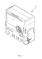
Figure 1 is a stereograph illustrating an embodiment of the appearance structure of the present invention; -
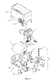
Figure 2 is an exploded view illustrating the combination relation of the main components of the present invention; -
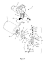
Figure 3 is an exploded view illustrating the combination relation of the main components of the supplying apparatus in the present invention; -
Figure 4 is a stereograph illustrating the appearance structure of the supplying apparatus in the present invention; -
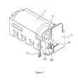
Figure 5 is a stereograph illustrating the partial appearance structure of the supplying apparatus after it has been mounted in the machine body in the present invention; -
Figure 6 is a plan view illustrating the appearance of the supplying apparatus after it has been set in the state of air supply in the present invention; -
Figure 7 is a sectional view taken in the direction of the arrows A-A inFigure 6 ; -
Figure 8 is a plan view illustrating the appearance of the supplying apparatus after it has been set in the state of sizing supply in the present invention; and -
Figure 9 is a sectional view taken in the direction of the arrows B-B inFigure 8 . -
- A......Tire Repair Machine
- B ...... Switching Unit
- 1...... Gas Supply Unit
- 11......Motor
- 12......Air Compressor
- 13 ...... Gas Distributing Head
- 130......Inlet
- 131...... First Outlet
- 132...... Second Outlet
- 2 ...... Joint Seat
- 21...... First Gas Inlet
- 22 ...... First Gas Outlet
- 23 ...... Second Gas Inlet
- 24...... Second Gas Outlet
- 25 ...... Screw Hole
- 26......Fixing Component
- 3 ...... Valve Seat
- 31...... Plunger Hole
- 32......First Via
- 33...... Second Via
- 34...... Perforation
- 35 ...... Screw
- 36...... Third Via
- 37 ...... Fourth Via
- 4...... Plunger
- 40...... Central Hole
- 41......Plunger Body
- 411...... First Annular Region
- 412...... Second Annular Region
- 413 ...... Third Annular Region
- 42...... First Through Hole
- 43 ...... Second Through Hole
- 44...... Leakage Stop Ring
- 5...... Sizing Barrel
- 51...... Outlet for Gas and Sizing
- 52......Gas Inlet
- 53......Connection Nozzle
- 54...... Air Supply Pipe
- 6 ...... Linkage Part
- 61...... Connecting Rod
- 611......Pivot
- 62......Operating Component
- 621...... Protruding Part
- 622...... Cover Body
- 7 ...... Housing
- 71...... Lower Shell
- 711...... Opening
- 72 ...... Upper Shell
- 73 ...... Safety Cover
- 731......Retaining Part
- 74......Pressure Gauge
- 75 ...... Display Panel
- Below the implementation of the present invention is explained in more detail in coordination with schemas and component symbols so that those skills familiar with this technology can practice the present invention after reading the specification.
- An integrated supplying apparatus for gas and sizing provided in the present invention can be applied to the tire repair machine A as shown in
Figure 1 . - As shown in
Figures 2 ,3 and4 , for the integrated supplying apparatus for gas and sizing provided in the present invention, its preferred embodiment includes agas supply unit 1, a sizingbarrel 5 and a switching unit B. Thegas supply unit 1 further comprises anair compressor 12 that is connected with amotor 11 and agas distributing head 13. Thegas distributing head 13 is provided with aninlet 130, afirst outlet 131 and asecond outlet 132; wherein theinlet 130 is connected with a gas outlet (not shown in the figure) of theair compressor 12. Herein, when themotor 11 is energized by electric power, it can drive theair compressor 12 to produce high pressure air which can simultaneously flow out through thefirst outlet 131 and thesecond outlet 132. The sizingbarrel 5 is one kind of container operable to hold the sizing for sealing and repairing a tire. It is provided with agas inlet 51 and an outlet for gas and sizing 52; wherein the former is only operable to provide a channel for air flowing through, while the latter is operable to provide a channel for both air and sizing flowing through. The outlet for gas and sizing 52 is arranged at the mouth of the sizingbarrel 5. The mouth is provided with an external thread so as to be screwed with ajoint seat 2 of the following switching unit B. On the other hand, thegas inlet 51 can be combined with aconnection nozzle 53 which is further combined with agas supply tube 54. Thegas supply tube 54 can then be connected with a fourth via 37 of the switching unit B which will be described in the following. - In a preferred embodiment of the present invention, the switching unit B includes a
joint seat 2, avalve seat 3, aplunger 4 and alinkage part 6. Herein, thejoint seat 2 can be firstly molded by casting and further be processed to form afirst gas inlet 21, afirst gas outlet 22, asecond gas inlet 23 and asecond gas outlet 24; wherein thefirst gas inlet 21 is connected with thefirst gas outlet 22, and thesecond gas inlet 23 in turn is connected with thesecond gas outlet 24. Thejoint seat 2 is provided with two or more screw holes 25 by its side so as to be combined with thevalve seat 3. Besides, thefirst gas inlet 21 is operable to combine with thefirst outlet 131 of thegas distributing head 13. - The
valve seat 3 can also be molded by casting and further be processed to form aplunger hole 31 and four vias (i.e. a first via 32, a second via 33, a third via 36 and a fourth via 37) connecting with theplunger hole 31. Taken an upright axis of theplunger hole 31 as the reference, such fourvias third vias Several perforations 34 corresponding to the screw holes 25 of thejoint seat 2 is provided by the side of thevalve seat 3. Herein, screws 35 can be used to pass through theseperforations 34 and then lock into therespective screw hole 25 of thejoint seat 2 so as to combine and fix thevalve seat 3 to thejoint seat 2. When thevalve seat 3 and thejoint seat 2 are combined together, the first via 32 and the second via 36 provided in the cylindrical body insert into thefirst gas outlet 22 and thesecond gas inlet 23 respectively. Moreover, the inner diameter of the cylindrical body, the first via 32 and the third via 36 are sealed by virtue of aleakage stop ring 44. The second via 33 is connected with a filling tube (now shown in the figure) with a filling nozzle arranged at one end thereof. - The
plunger 4 of the switching unit B is a cylindrical body which almost has the same outer diameter as the inner diameter of theplunger hole 31 of thevalve seat 3. Theplunger 4 has acentral hole 40 extending axially throughout to one end of the plunger. Theplunger 4 is processed to form a firstannular region 411, a secondannular region 412 and a thirdannular region 413 on its outer diameter, wherein the diameter at the bottom of these annular regions is smaller than the outer diameter of theplunger 4, a first throughhole 42 and a second throughhole 43 are arranged on the plunger wall of the first and thirdannular regions annular regions leakage stop ring 44 respectively. When theplunger 4 is combined to theplunger hole 31 of thevalve seat 3, theleakage stop ring 44 is used to implement the sealing between theplunger 4 and theplunger hole 31 so as to prevent gas leakage. At this moment, theplunger 4 can move axially between a first stroke and a second stroke that are in the opposite direction relative to each other in theplunger hole 31. In the embodiment shown inFigure 7 , the first stroke refers to a limit where theplunger 4 can move upwards as possible, and the second stroke in turn refers to a limit where theplunger 4 can move downwards as possible. Herein, when theplunger 4 has moved to the first stroke, the second via 32 is corresponding to the position of the secondannular region 412, so that the first via 32 is connected to the second via 33 through the secondannular region 412. As shown inFigure 9 , when theplunger 4 has moved to the second stroke, the first via 32 is corresponding to the position of the firstannular region 411, so that the first via 32 is connected to the first throughhole 42, the third via 36 is connected to the second via 33 through the secondannular region 412, and the fourth via 37 is connected to the second throughhole 43 through the thirdannular region 413. - The
linkage par 6 of the switching unit B is used to connect theplunger 4 so as to make theplunger 4 move between the first and second stroke, thereby controlling the operating apparatus for outputting the gas or sizing. Thelinkage part 6 of the present invention includes a connectingrod 61 and anoperating component 62. Herein, a first end of the connectingrod 61 is pivoted to the upper end of theplunger 4 by a pivot, a second end of the connectingrod 61 is pivoted to the operatingcomponent 62, and one end of the operatingcomponent 62 is pivoted to thevalve seat 3 at a proper position. The operatingcomponent 62 has aprotruding part 621 which is molded by bending and further provided with acover body 622. By virtue ofsuch cover body 622, it is convenient for the user to touch and operate by his/her fingers. As shown inFigures 6 and7 , when the operatingcomponent 62 is wrenched upward, theplunger 4 is driven to move towards the first stroke under the linkage action of the operatingcomponent 62 and the connectingrod 61, in which case the aforementionedfirst outlet 131, the first via 32 and the second via 33 together form a path. A shown inFigures 8 and9 , when the operatingcomponent 62 is wrenched downward, theplunger 4 is driven to move towards the second stroke under the linkage action of the operatingcomponent 62 and the connectingrod 61, in which case the aforementionedfirst outlet 131, the first throughhole 42, thecentral hole 40, the second throughhole 43 and the fourth via 37 together form a path. At this moment, thesecond gas outlet 24, the third via 36 and the second via 33 together form a path as well. - As shown in
Figure 2 again, theaforementioned sizing barrel 5, thegas supply unit 1 and the switching unit B are all arranged inside a housing 7. In a preferred embodiment of the present invention, the housing 7 is comprised of alower shell 71 and anupper shell 72, wherein thejoint seat 2 is fixed within thelower shell 71 by utilization of a fixingcomponent 26. The fixingcomponent 26 is in the shape of circular arc so that it can be sheathed around the curved surface part of thejoint seat 2 and then fixed to thelower shell 71 by screw. Thelower shell 71 is provided with an opening 711, and asafety cover 73 is provided by one side of the opening 711. Herein, thesafety cover 73 is provided with a retainingpart 731 protruding from the inner side of the safety cover 73 (as shown inFigure 5 ). When theaforementioned sizing barrel 5, thegas supply unit 1 and the switching unit B are firstly assembled in thelower shell 71, theupper shell 72 is then combined above thelower shell 71. Again as shown inFigure 5 , the function of thesafety cover 73 in the present invention is described as follows: when theplunger 4 is in the state where it is located in the first stroke (i.e. when the operatingcomponent 62 is wrenched upward), thesafety cover 73 can cover such opening 711 and the retainingpart 731 can block the lower part of theprotruding part 621 of the operatingcomponent 62 so as to prevent theoperating component 62 from being operated. In such state, the integrated supplying apparatus of the present invention can be only used for outputting high pressure air, and it is also prevented from outputting the sizing, so that the user is free of mis-operation. Instead, when the user plans to repair the tire by virtue of some outputted sizing, thesafety cover 73 has to be opened at first, so that the retainingpart 731 is removed from blocking theprotruding part 621. Thereafter, the operatingcomponent 62 can be wrenched downward by the user, so that theplunger 4 can move to the second stroke to output the sizing. - The
upper shell 72 can be further provided with adisplay panel 75 and apressure gauge 74. Herein thepressure gauge 74 is connected with thesecond outlet 132 of thegas distributing head 13 by a pipeline. Accordingly, the air pressure fed to thejoint seat 2 by theair compressor 12 can be displayed by thepressure gauge 74 synchronously, in which case the user can determine and adjust the inflation time accordingly. Thedisplay panel 75 can be a light guide plate with an inclined surface and a backlight (not shown in the figures) on its backside. It is arranged on the surface of the housing 7 so as to display the related information more clearly. - The operation method of the present invention is shown as follows.
- The tire repair machine A can be carried in a vehicle by the user. In this way, in the event that the user determines to inflate a tire by himself without obtaining tire inflation service from an automobile repair station, this tire repair machine A can be taken out for usage. Without taking off the safety cover 73 (as shown in
Figure 1 andFigure 6 ), the operatingcomponent 62 of thelinkage part 6 is maintained in an upper position; that is, theplunger 4 is maintained in the state where it is located in the first stroke. At this moment, the user starts the power supply so that themotor 11 can drive theair compressor 12 to produce high pressure gas, wherein the high pressure gas simultaneously flows out through thefirst outlet 131 and thesecond outlet 132 and the gas pressure can be further displayed on thepressure gauge 74. As shown inFigure 7 , the high pressure gas flowing out from thefirst outlet 131 subsequently flows out from the second via 33 by passing through thefirst gas inlet 21, the first via 32 and the secondannular region 412, finally, the high pressure gas can be used for the air inflation on the tire via the inflation tube and the filling nozzle (not shown in the figure). - When it is intended to repair a tire with rupture and air leakage, the
safety cover 73 has to be opened at first so that the retainingpart 731 is removed from blocking the operatingcomponent 62. In this case, the operatingcomponent 62 can be wrenched downward, and theplunger 4 can be moved axially toward the second stroke under the linkage action of the connecting rod 61 (as shown inFigures 8 and9 ). Herein, the firstannular region 411 of theplunger 4 moves to a position corresponding to the first via 32, the secondannular region 412 moves to a position corresponding to the third via 36, and the thirdannular region 413 moves to a position corresponding to the fourth via 37. Thus, the high pressure gas flowing out from thefirst outlet 131 subsequently enters the sizingbarrel 5 by passing through thefirst gas inlet 21, the first via 32, the firstannular region 411, the first throughhole 42, thecentral hole 40, the second throughhole 43 and the fourth via 37. In this case, the sizing inside the sizingbarrel 5 is pushed out through the outlet for gas and sizing 51 under the action of the air pressure. The sizing then flows out from the second via 33 by passing through thesecond gas outlet 24, the third via 36 and the secondannular region 412. After that, the sizing is injected into the tire via a filling line connected with the second throughhole 32 and a filling nozzle connected with the air nozzle of the tire. When all the sizing inside the sizing barrel is used up, the gas inside the sizingbarrel 5 is continued to be injected into the tire so that a certain pressure can be maintained within the tire. In the following, the filling nozzle is dismounted immediately, and the vehicle is made to run slowly for a certain distance in such a way the sizing can flow uniformly along the surface of the inner wall of the tire to fill in the rupture location. The sizing can prevent the air inside the tire from leakage when it is solidified. In this case, the driver can drive the vehicle to a repair station nearby for further overhauling. - The preferred embodiments mentioned above are only intended to illustrate the present invention. Instead, they are not intended to limit the present invention in any form. Therefore, any modifications or alternations related to the present invention should be included in the scope of present invention, as long as they are made within the spirit of the present invention.
Claims (7)
- An integrated supplying apparatus for gas and sizing, comprising:a sizing barrel provided with at least one gas inlet and at least one outlet for gas and sizing; wherein the sizing barrel is loaded with sizing;a gas supply unit comprising an air compressor;a switching unit comprising a valve seat, a plunger and a linkage part;wherein, the valve seat has a plunger hole, and it also provided with a first via, a second via, a third via and a fourth via for connecting the inside and outside of the plunger hole; wherein the first via is connected with a gas outlet of the air compressor, the second via is connected with a filling nozzle, the third via is connected with the outlet for gas and sizing of the sizing barrel, and the fourth via is connected with the gas inlet of the sizing barrel;the plunger has a central hole extending axially throughout to one end of the plunger, and it has a first annular region, a second annular region and a third annular region on its outer diameter, wherein a first through hole and a second through hole are arranged in the plunger wall of the first and third annular regions respectively, and both ends of the respective first, second and third annular regions are provided with a leakage stop ring respectively; the plunger is combined to the plunger hole of the valve seat so that the plunger can move axially between a first stroke and a second stroke that are in the opposite direction relative to each other in the plunger hole; when the plunger has moved to the first stroke, the first via is connected to the second via through the second annular region, in which case the gas is directly output by the second via; when the plunger has moved to the second stroke, the first via is connected to the first through hole through the first annular region, the third via is connected to the second via through the second annular region, and the fourth via is connected to the second through hole through the third annular region, in which case the gas is eventually input into the sizing barrel through the fourth via, so that the sizing inside the sizing barrel is output by virtue of the third and second vias under the action of gas pressure;the linkage part is connected with the plunger so as to make the plunger move between the first and second stroke.
- The integrated supplying apparatus for gas and sizing of claim 1, wherein the switching unit is also comprised of a joint seat; the joint seat has a first gas inlet, a first gas outlet, a second gas inlet and a second gas outlet; wherein, the first gas inlet is connected with the gas outlet of the air compressor, the first gas outlet is connected with the first via of the valve seat, the second gas inlet is connected with the third via of the valve seat, and the second gas outlet is connected with the outlet for gas and sizing of the sizing barrel.
- The integrated supplying apparatus for gas and sizing of claim 1, wherein the linkage part includes a connecting rod and an operating component; the two ends of the connecting rod are respectively pivoted to the plunger and the operating component, and one end of the operating component is pivoted to the valve seat; when the operating component is being operated, the plunger is driven to move between the first stroke and the second stroke by virtue of the connecting rod.
- The integrated supplying apparatus for gas and sizing of claim 3, wherein the operating component is provided with a protruding part, which is further provided with a cover body.
- The integrated supplying apparatus for gas and sizing of claim 4, wherein all of the sizing barrel, the gas supply unit and the switching unit are arranged inside a housing; an opening with the safety cover is provided on the housing, and the safety cover is further equipped with a retaining part; when the plunger is in the first state of the first stroke, the safety cover can cover such opening and the retaining part can block the lower part of the protruding part so as to prevent the operating component from being operated; when the safety cover is opened, the retaining part is removed from the lower part of the protruding part so that the operating component can be operated.
- The integrated supplying apparatus for gas and sizing of claim 5, wherein a gas distributing head is connected with the gas outlet of the air compressor; the gas distributing head is provided with a first outlet and a second outlet; wherein the first outlet is connected with the first gas inlet of the joint seat, and the second outlet is connected with a pressure gauge installed on the housing.
- The integrated supplying apparatus for gas and sizing of claim 1, wherein the integrated supplying apparatus for gas and sizing is applied to tire repair machines, in which the sizing is used as the material for filling in the hole of a broken tire.
Applications Claiming Priority (2)
| Application Number | Priority Date | Filing Date | Title |
|---|---|---|---|
| TW101201894 | 2012-02-02 | ||
| PCT/CN2012/079447 WO2013113215A1 (en) | 2012-02-02 | 2012-07-31 | Supply apparatus for integrating gas and rubber compound |
Publications (2)
| Publication Number | Publication Date |
|---|---|
| EP2881243A1 true EP2881243A1 (en) | 2015-06-10 |
| EP2881243A4 EP2881243A4 (en) | 2016-07-06 |
Family
ID=46980654
Family Applications (1)
| Application Number | Title | Priority Date | Filing Date |
|---|---|---|---|
| EP12867177.3A Withdrawn EP2881243A4 (en) | 2012-02-02 | 2012-07-31 | SUPPLY APPARATUS FOR INTEGRATING GAS AND RUBBER MIXTURE |
Country Status (9)
| Country | Link |
|---|---|
| US (1) | US8720495B2 (en) |
| EP (1) | EP2881243A4 (en) |
| JP (1) | JP3179491U (en) |
| KR (1) | KR200482999Y1 (en) |
| CN (1) | CN202753450U (en) |
| AU (1) | AU2012101427B4 (en) |
| CA (1) | CA2880534A1 (en) |
| HK (1) | HK1210101A1 (en) |
| WO (1) | WO2013113215A1 (en) |
Families Citing this family (6)
| Publication number | Priority date | Publication date | Assignee | Title |
|---|---|---|---|---|
| WO2015058372A2 (en) * | 2013-10-23 | 2015-04-30 | 精联科技有限公司 | Tyre repair machine |
| US9902375B2 (en) * | 2014-01-13 | 2018-02-27 | Wai Kan Wong | Device used for pressing air and/or tire sealant into a tire and a compression part |
| TWI583572B (en) * | 2014-11-18 | 2017-05-21 | 周文三 | First aid device for broken tires |
| DE102015117954A1 (en) * | 2015-10-21 | 2017-04-27 | Illinois Tool Works Inc. | Method and device for dispensing a means for sealing an inflatable article |
| EP3496937A4 (en) * | 2016-08-15 | 2020-04-08 | Consumer Products International LLC | APPARATUS AND METHODS FOR INFLATING AND REPAIRING COIN-OPERATED TIRES |
| DE102019217775A1 (en) * | 2019-11-19 | 2021-05-20 | Continental Reifen Deutschland Gmbh | Device for transporting compressed air and / or sealant into a pneumatic vehicle tire and portable / transportable system for sealing and inflating pneumatic vehicle tires |
Family Cites Families (20)
| Publication number | Priority date | Publication date | Assignee | Title |
|---|---|---|---|---|
| PL202965B1 (en) * | 2001-02-16 | 2009-08-31 | Continental Ag | Device for sealing and inflating an inflatable object |
| US20050076951A1 (en) * | 2003-10-06 | 2005-04-14 | Gray John M. | Pressure actuated valve |
| US7615122B2 (en) * | 2005-05-02 | 2009-11-10 | Ecolab Inc. | Method and apparatus for dispensing a use solution |
| CN101244631A (en) * | 2007-02-15 | 2008-08-20 | 冠翔(香港)工业有限公司 | tire pot |
| US7748295B2 (en) * | 2007-02-23 | 2010-07-06 | Active Tools International (Hk) Ltd. | Tire-repair bottle |
| JP4927657B2 (en) * | 2007-07-27 | 2012-05-09 | 株式会社ブリヂストン | Valve adapter and sealing / pump-up device provided with the same |
| JP4705655B2 (en) | 2008-03-25 | 2011-06-22 | 住友ゴム工業株式会社 | Integrated tire puncture repair device |
| JP5496183B2 (en) * | 2008-04-21 | 2014-05-21 | エマーソン プロセス マネージメント レギュレーター テクノロジーズ インコーポレイテッド | Valve body with double detection mechanism |
| KR100867277B1 (en) * | 2008-05-30 | 2008-11-06 | (주) 신우금형 | Method for repairing tire mold using cold spray technology |
| JP5054627B2 (en) * | 2008-07-15 | 2012-10-24 | 住友ゴム工業株式会社 | Sealing agent container lid unit |
| US20100108185A1 (en) * | 2008-11-04 | 2010-05-06 | Wen San Chou | Air compressor and tire repairing combination |
| US8522833B2 (en) * | 2008-11-04 | 2013-09-03 | Wen San Chou | Device for sealing and inflating inflatable object |
| JP5291536B2 (en) | 2009-05-26 | 2013-09-18 | 住友ゴム工業株式会社 | Integrated tire puncture repair device |
| CN102348552A (en) | 2009-07-10 | 2012-02-08 | 冠翔(香港)工业有限公司 | Valve for tire repair kit |
| CN201483776U (en) * | 2009-09-04 | 2010-05-26 | 高正东 | Automatic inflation tire patching device |
| JP4743328B2 (en) * | 2010-01-15 | 2011-08-10 | 横浜ゴム株式会社 | Puncture repair liquid recovery method and recovery device |
| KR101187377B1 (en) * | 2010-03-03 | 2012-10-04 | 웬-산 초우 | Air injection type air compressor for repairing tire |
| CN102602013A (en) * | 2012-04-01 | 2012-07-25 | 东莞瑞柯电子科技股份有限公司 | A kind of glue bottle for pneumatic tire repair and pneumatic tire repair machine |
| TWM444270U (en) * | 2012-04-16 | 2013-01-01 | 冠翔(香港)工業有限公司 | Integrated supply of gas and rubber (2) |
| TWM462676U (en) * | 2013-05-03 | 2013-10-01 | 冠翔(香港)工業有限公司 | Quick connection and separation device for tire repairing machine |
-
2012
- 2012-07-31 CA CA 2880534 patent/CA2880534A1/en not_active Abandoned
- 2012-07-31 WO PCT/CN2012/079447 patent/WO2013113215A1/en not_active Ceased
- 2012-07-31 EP EP12867177.3A patent/EP2881243A4/en not_active Withdrawn
- 2012-07-31 HK HK15110713.8A patent/HK1210101A1/en unknown
- 2012-07-31 CN CN2012203747696U patent/CN202753450U/en not_active Expired - Lifetime
- 2012-08-24 JP JP2012005187U patent/JP3179491U/en not_active Expired - Fee Related
- 2012-09-14 US US13/616,082 patent/US8720495B2/en not_active Expired - Fee Related
- 2012-09-17 AU AU2012101427A patent/AU2012101427B4/en not_active Expired
-
2013
- 2013-01-07 KR KR2020130000124U patent/KR200482999Y1/en not_active Expired - Fee Related
Also Published As
| Publication number | Publication date |
|---|---|
| KR200482999Y1 (en) | 2017-03-24 |
| CN202753450U (en) | 2013-02-27 |
| US8720495B2 (en) | 2014-05-13 |
| JP3179491U (en) | 2012-11-01 |
| WO2013113215A8 (en) | 2014-12-11 |
| AU2012101427A4 (en) | 2012-10-11 |
| KR20130004843U (en) | 2013-08-12 |
| CA2880534A1 (en) | 2013-08-08 |
| WO2013113215A1 (en) | 2013-08-08 |
| HK1210101A1 (en) | 2016-04-15 |
| EP2881243A4 (en) | 2016-07-06 |
| AU2012101427B4 (en) | 2013-06-06 |
| US20130199638A1 (en) | 2013-08-08 |
Similar Documents
| Publication | Publication Date | Title |
|---|---|---|
| AU2012101427A4 (en) | Integrated Supplying Apparatus for Gas and Sizing | |
| KR101484094B1 (en) | Pipe structure of serially-connected hoses used in an air compressor for a vehicle | |
| US7748295B2 (en) | Tire-repair bottle | |
| EP2542402B1 (en) | Apparatus for the introduction of air and/or sealant into a tire | |
| JP5054627B2 (en) | Sealing agent container lid unit | |
| EP2881244B1 (en) | Heat dissipation structure of tire repairing machine | |
| CN101506089A (en) | Electromechanically operated fuel nozzle | |
| CN114728480A (en) | Device for delivering compressed air and/or sealant into vehicle tires and portable/deliverable system for sealing and inflating vehicle tires | |
| CN101890886A (en) | Apparatus for repairing and inflating inflatable articles | |
| US8863779B2 (en) | Integrated supplying apparatus for gas and sizing | |
| JP2001212883A (en) | Integrated puncture emergency repair device | |
| WO2023284779A1 (en) | Tire repair tool and application thereof | |
| JP2011131546A (en) | Sealing and pumping-up device | |
| EP2881245A1 (en) | Integrated gas and sizing material supply device | |
| JP2011131547A (en) | Sealing and pumping-up device | |
| JP2006103498A (en) | Sealing pump-up device of tire | |
| TWM456905U (en) | Integrated gas and plastic supplying device | |
| JP2008137277A (en) | Air pressure displaying mechanism for sealing/pumping-up apparatus | |
| JP2007181968A (en) | Pump up device | |
| JP2010017857A (en) | Sealing pump-up device | |
| WO2024118511A2 (en) | Usb pd-powered compressor/tire repair kit | |
| JP2010253764A (en) | Sealing / pump-up device |
Legal Events
| Date | Code | Title | Description |
|---|---|---|---|
| PUAI | Public reference made under article 153(3) epc to a published international application that has entered the european phase |
Free format text: ORIGINAL CODE: 0009012 |
|
| 17P | Request for examination filed |
Effective date: 20150217 |
|
| AK | Designated contracting states |
Kind code of ref document: A1 Designated state(s): AL AT BE BG CH CY CZ DE DK EE ES FI FR GB GR HR HU IE IS IT LI LT LU LV MC MK MT NL NO PL PT RO RS SE SI SK SM TR |
|
| AX | Request for extension of the european patent |
Extension state: BA ME |
|
| DAX | Request for extension of the european patent (deleted) | ||
| REG | Reference to a national code |
Ref country code: HK Ref legal event code: DE Ref document number: 1210101 Country of ref document: HK |
|
| RA4 | Supplementary search report drawn up and despatched (corrected) |
Effective date: 20160607 |
|
| RIC1 | Information provided on ipc code assigned before grant |
Ipc: B29L 30/00 20060101ALI20160601BHEP Ipc: B29C 73/16 20060101AFI20160601BHEP |
|
| GRAP | Despatch of communication of intention to grant a patent |
Free format text: ORIGINAL CODE: EPIDOSNIGR1 |
|
| INTG | Intention to grant announced |
Effective date: 20190404 |
|
| STAA | Information on the status of an ep patent application or granted ep patent |
Free format text: STATUS: THE APPLICATION IS DEEMED TO BE WITHDRAWN |
|
| 18D | Application deemed to be withdrawn |
Effective date: 20190815 |
|
| REG | Reference to a national code |
Ref country code: HK Ref legal event code: WD Ref document number: 1210101 Country of ref document: HK |