EP2881232B1 - Method for producing ring-shaped insert molded articles - Google Patents
Method for producing ring-shaped insert molded articles Download PDFInfo
- Publication number
- EP2881232B1 EP2881232B1 EP14194633.5A EP14194633A EP2881232B1 EP 2881232 B1 EP2881232 B1 EP 2881232B1 EP 14194633 A EP14194633 A EP 14194633A EP 2881232 B1 EP2881232 B1 EP 2881232B1
- Authority
- EP
- European Patent Office
- Prior art keywords
- plastic
- ring
- gate
- molded article
- insert
- Prior art date
- Legal status (The legal status is an assumption and is not a legal conclusion. Google has not performed a legal analysis and makes no representation as to the accuracy of the status listed.)
- Active
Links
Images




Classifications
-
- B—PERFORMING OPERATIONS; TRANSPORTING
- B29—WORKING OF PLASTICS; WORKING OF SUBSTANCES IN A PLASTIC STATE IN GENERAL
- B29C—SHAPING OR JOINING OF PLASTICS; SHAPING OF MATERIAL IN A PLASTIC STATE, NOT OTHERWISE PROVIDED FOR; AFTER-TREATMENT OF THE SHAPED PRODUCTS, e.g. REPAIRING
- B29C45/00—Injection moulding, i.e. forcing the required volume of moulding material through a nozzle into a closed mould; Apparatus therefor
- B29C45/17—Component parts, details or accessories; Auxiliary operations
- B29C45/26—Moulds
- B29C45/27—Sprue channels ; Runner channels or runner nozzles
- B29C45/2701—Details not specific to hot or cold runner channels
- B29C45/2708—Gates
-
- B—PERFORMING OPERATIONS; TRANSPORTING
- B29—WORKING OF PLASTICS; WORKING OF SUBSTANCES IN A PLASTIC STATE IN GENERAL
- B29C—SHAPING OR JOINING OF PLASTICS; SHAPING OF MATERIAL IN A PLASTIC STATE, NOT OTHERWISE PROVIDED FOR; AFTER-TREATMENT OF THE SHAPED PRODUCTS, e.g. REPAIRING
- B29C45/00—Injection moulding, i.e. forcing the required volume of moulding material through a nozzle into a closed mould; Apparatus therefor
- B29C45/0025—Preventing defects on the moulded article, e.g. weld lines, shrinkage marks
-
- B—PERFORMING OPERATIONS; TRANSPORTING
- B29—WORKING OF PLASTICS; WORKING OF SUBSTANCES IN A PLASTIC STATE IN GENERAL
- B29C—SHAPING OR JOINING OF PLASTICS; SHAPING OF MATERIAL IN A PLASTIC STATE, NOT OTHERWISE PROVIDED FOR; AFTER-TREATMENT OF THE SHAPED PRODUCTS, e.g. REPAIRING
- B29C45/00—Injection moulding, i.e. forcing the required volume of moulding material through a nozzle into a closed mould; Apparatus therefor
- B29C45/14—Injection moulding, i.e. forcing the required volume of moulding material through a nozzle into a closed mould; Apparatus therefor incorporating preformed parts or layers, e.g. injection moulding around inserts or for coating articles
- B29C45/14336—Coating a portion of the article, e.g. the edge of the article
- B29C45/14418—Sealing means between mould and article
-
- B—PERFORMING OPERATIONS; TRANSPORTING
- B29—WORKING OF PLASTICS; WORKING OF SUBSTANCES IN A PLASTIC STATE IN GENERAL
- B29C—SHAPING OR JOINING OF PLASTICS; SHAPING OF MATERIAL IN A PLASTIC STATE, NOT OTHERWISE PROVIDED FOR; AFTER-TREATMENT OF THE SHAPED PRODUCTS, e.g. REPAIRING
- B29C45/00—Injection moulding, i.e. forcing the required volume of moulding material through a nozzle into a closed mould; Apparatus therefor
- B29C45/14—Injection moulding, i.e. forcing the required volume of moulding material through a nozzle into a closed mould; Apparatus therefor incorporating preformed parts or layers, e.g. injection moulding around inserts or for coating articles
- B29C45/1459—Coating annular articles
-
- B—PERFORMING OPERATIONS; TRANSPORTING
- B29—WORKING OF PLASTICS; WORKING OF SUBSTANCES IN A PLASTIC STATE IN GENERAL
- B29C—SHAPING OR JOINING OF PLASTICS; SHAPING OF MATERIAL IN A PLASTIC STATE, NOT OTHERWISE PROVIDED FOR; AFTER-TREATMENT OF THE SHAPED PRODUCTS, e.g. REPAIRING
- B29C45/00—Injection moulding, i.e. forcing the required volume of moulding material through a nozzle into a closed mould; Apparatus therefor
- B29C45/17—Component parts, details or accessories; Auxiliary operations
- B29C45/38—Cutting-off equipment for sprues or ingates
-
- G—PHYSICS
- G01—MEASURING; TESTING
- G01D—MEASURING NOT SPECIALLY ADAPTED FOR A SPECIFIC VARIABLE; ARRANGEMENTS FOR MEASURING TWO OR MORE VARIABLES NOT COVERED IN A SINGLE OTHER SUBCLASS; TARIFF METERING APPARATUS; MEASURING OR TESTING NOT OTHERWISE PROVIDED FOR
- G01D5/00—Mechanical means for transferring the output of a sensing member; Means for converting the output of a sensing member to another variable where the form or nature of the sensing member does not constrain the means for converting; Transducers not specially adapted for a specific variable
- G01D5/12—Mechanical means for transferring the output of a sensing member; Means for converting the output of a sensing member to another variable where the form or nature of the sensing member does not constrain the means for converting; Transducers not specially adapted for a specific variable using electric or magnetic means
-
- G—PHYSICS
- G01—MEASURING; TESTING
- G01D—MEASURING NOT SPECIALLY ADAPTED FOR A SPECIFIC VARIABLE; ARRANGEMENTS FOR MEASURING TWO OR MORE VARIABLES NOT COVERED IN A SINGLE OTHER SUBCLASS; TARIFF METERING APPARATUS; MEASURING OR TESTING NOT OTHERWISE PROVIDED FOR
- G01D5/00—Mechanical means for transferring the output of a sensing member; Means for converting the output of a sensing member to another variable where the form or nature of the sensing member does not constrain the means for converting; Transducers not specially adapted for a specific variable
- G01D5/12—Mechanical means for transferring the output of a sensing member; Means for converting the output of a sensing member to another variable where the form or nature of the sensing member does not constrain the means for converting; Transducers not specially adapted for a specific variable using electric or magnetic means
- G01D5/244—Mechanical means for transferring the output of a sensing member; Means for converting the output of a sensing member to another variable where the form or nature of the sensing member does not constrain the means for converting; Transducers not specially adapted for a specific variable using electric or magnetic means influencing characteristics of pulses or pulse trains; generating pulses or pulse trains
-
- B—PERFORMING OPERATIONS; TRANSPORTING
- B29—WORKING OF PLASTICS; WORKING OF SUBSTANCES IN A PLASTIC STATE IN GENERAL
- B29C—SHAPING OR JOINING OF PLASTICS; SHAPING OF MATERIAL IN A PLASTIC STATE, NOT OTHERWISE PROVIDED FOR; AFTER-TREATMENT OF THE SHAPED PRODUCTS, e.g. REPAIRING
- B29C45/00—Injection moulding, i.e. forcing the required volume of moulding material through a nozzle into a closed mould; Apparatus therefor
- B29C45/0025—Preventing defects on the moulded article, e.g. weld lines, shrinkage marks
- B29C2045/0027—Gate or gate mark locations
-
- B—PERFORMING OPERATIONS; TRANSPORTING
- B29—WORKING OF PLASTICS; WORKING OF SUBSTANCES IN A PLASTIC STATE IN GENERAL
- B29C—SHAPING OR JOINING OF PLASTICS; SHAPING OF MATERIAL IN A PLASTIC STATE, NOT OTHERWISE PROVIDED FOR; AFTER-TREATMENT OF THE SHAPED PRODUCTS, e.g. REPAIRING
- B29C45/00—Injection moulding, i.e. forcing the required volume of moulding material through a nozzle into a closed mould; Apparatus therefor
- B29C45/17—Component parts, details or accessories; Auxiliary operations
- B29C45/26—Moulds
- B29C45/27—Sprue channels ; Runner channels or runner nozzles
- B29C45/2701—Details not specific to hot or cold runner channels
- B29C45/2708—Gates
- B29C2045/2714—Gates elongated, e.g. film-like, annular
-
- B—PERFORMING OPERATIONS; TRANSPORTING
- B29—WORKING OF PLASTICS; WORKING OF SUBSTANCES IN A PLASTIC STATE IN GENERAL
- B29C—SHAPING OR JOINING OF PLASTICS; SHAPING OF MATERIAL IN A PLASTIC STATE, NOT OTHERWISE PROVIDED FOR; AFTER-TREATMENT OF THE SHAPED PRODUCTS, e.g. REPAIRING
- B29C45/00—Injection moulding, i.e. forcing the required volume of moulding material through a nozzle into a closed mould; Apparatus therefor
- B29C45/17—Component parts, details or accessories; Auxiliary operations
- B29C45/26—Moulds
- B29C45/27—Sprue channels ; Runner channels or runner nozzles
- B29C45/2701—Details not specific to hot or cold runner channels
- B29C45/2708—Gates
- B29C2045/2716—The gate axis being perpendicular to main injection axis, e.g. injecting into side walls of a container
-
- B—PERFORMING OPERATIONS; TRANSPORTING
- B29—WORKING OF PLASTICS; WORKING OF SUBSTANCES IN A PLASTIC STATE IN GENERAL
- B29C—SHAPING OR JOINING OF PLASTICS; SHAPING OF MATERIAL IN A PLASTIC STATE, NOT OTHERWISE PROVIDED FOR; AFTER-TREATMENT OF THE SHAPED PRODUCTS, e.g. REPAIRING
- B29C45/00—Injection moulding, i.e. forcing the required volume of moulding material through a nozzle into a closed mould; Apparatus therefor
- B29C45/14—Injection moulding, i.e. forcing the required volume of moulding material through a nozzle into a closed mould; Apparatus therefor incorporating preformed parts or layers, e.g. injection moulding around inserts or for coating articles
- B29C45/14836—Preventing damage of inserts during injection, e.g. collapse of hollow inserts, breakage
-
- B—PERFORMING OPERATIONS; TRANSPORTING
- B29—WORKING OF PLASTICS; WORKING OF SUBSTANCES IN A PLASTIC STATE IN GENERAL
- B29K—INDEXING SCHEME ASSOCIATED WITH SUBCLASSES B29B, B29C OR B29D, RELATING TO MOULDING MATERIALS OR TO MATERIALS FOR MOULDS, REINFORCEMENTS, FILLERS OR PREFORMED PARTS, e.g. INSERTS
- B29K2077/00—Use of PA, i.e. polyamides, e.g. polyesteramides or derivatives thereof, as moulding material
-
- B—PERFORMING OPERATIONS; TRANSPORTING
- B29—WORKING OF PLASTICS; WORKING OF SUBSTANCES IN A PLASTIC STATE IN GENERAL
- B29K—INDEXING SCHEME ASSOCIATED WITH SUBCLASSES B29B, B29C OR B29D, RELATING TO MOULDING MATERIALS OR TO MATERIALS FOR MOULDS, REINFORCEMENTS, FILLERS OR PREFORMED PARTS, e.g. INSERTS
- B29K2081/00—Use of polymers having sulfur, with or without nitrogen, oxygen or carbon only, in the main chain, as moulding material
- B29K2081/04—Polysulfides, e.g. PPS, i.e. polyphenylene sulfide or derivatives thereof
-
- B—PERFORMING OPERATIONS; TRANSPORTING
- B29—WORKING OF PLASTICS; WORKING OF SUBSTANCES IN A PLASTIC STATE IN GENERAL
- B29K—INDEXING SCHEME ASSOCIATED WITH SUBCLASSES B29B, B29C OR B29D, RELATING TO MOULDING MATERIALS OR TO MATERIALS FOR MOULDS, REINFORCEMENTS, FILLERS OR PREFORMED PARTS, e.g. INSERTS
- B29K2101/00—Use of unspecified macromolecular compounds as moulding material
- B29K2101/10—Thermosetting resins
-
- B—PERFORMING OPERATIONS; TRANSPORTING
- B29—WORKING OF PLASTICS; WORKING OF SUBSTANCES IN A PLASTIC STATE IN GENERAL
- B29K—INDEXING SCHEME ASSOCIATED WITH SUBCLASSES B29B, B29C OR B29D, RELATING TO MOULDING MATERIALS OR TO MATERIALS FOR MOULDS, REINFORCEMENTS, FILLERS OR PREFORMED PARTS, e.g. INSERTS
- B29K2103/00—Use of resin-bonded materials as moulding material
- B29K2103/04—Inorganic materials
- B29K2103/06—Metal powders, metal carbides or the like
-
- B—PERFORMING OPERATIONS; TRANSPORTING
- B29—WORKING OF PLASTICS; WORKING OF SUBSTANCES IN A PLASTIC STATE IN GENERAL
- B29K—INDEXING SCHEME ASSOCIATED WITH SUBCLASSES B29B, B29C OR B29D, RELATING TO MOULDING MATERIALS OR TO MATERIALS FOR MOULDS, REINFORCEMENTS, FILLERS OR PREFORMED PARTS, e.g. INSERTS
- B29K2105/00—Condition, form or state of moulded material or of the material to be shaped
- B29K2105/06—Condition, form or state of moulded material or of the material to be shaped containing reinforcements, fillers or inserts
- B29K2105/16—Fillers
-
- B—PERFORMING OPERATIONS; TRANSPORTING
- B29—WORKING OF PLASTICS; WORKING OF SUBSTANCES IN A PLASTIC STATE IN GENERAL
- B29K—INDEXING SCHEME ASSOCIATED WITH SUBCLASSES B29B, B29C OR B29D, RELATING TO MOULDING MATERIALS OR TO MATERIALS FOR MOULDS, REINFORCEMENTS, FILLERS OR PREFORMED PARTS, e.g. INSERTS
- B29K2105/00—Condition, form or state of moulded material or of the material to be shaped
- B29K2105/25—Solid
- B29K2105/251—Particles, powder or granules
-
- B—PERFORMING OPERATIONS; TRANSPORTING
- B29—WORKING OF PLASTICS; WORKING OF SUBSTANCES IN A PLASTIC STATE IN GENERAL
- B29K—INDEXING SCHEME ASSOCIATED WITH SUBCLASSES B29B, B29C OR B29D, RELATING TO MOULDING MATERIALS OR TO MATERIALS FOR MOULDS, REINFORCEMENTS, FILLERS OR PREFORMED PARTS, e.g. INSERTS
- B29K2705/00—Use of metals, their alloys or their compounds, for preformed parts, e.g. for inserts
-
- B—PERFORMING OPERATIONS; TRANSPORTING
- B29—WORKING OF PLASTICS; WORKING OF SUBSTANCES IN A PLASTIC STATE IN GENERAL
- B29K—INDEXING SCHEME ASSOCIATED WITH SUBCLASSES B29B, B29C OR B29D, RELATING TO MOULDING MATERIALS OR TO MATERIALS FOR MOULDS, REINFORCEMENTS, FILLERS OR PREFORMED PARTS, e.g. INSERTS
- B29K2905/00—Use of metals, their alloys or their compounds, as mould material
-
- B—PERFORMING OPERATIONS; TRANSPORTING
- B29—WORKING OF PLASTICS; WORKING OF SUBSTANCES IN A PLASTIC STATE IN GENERAL
- B29K—INDEXING SCHEME ASSOCIATED WITH SUBCLASSES B29B, B29C OR B29D, RELATING TO MOULDING MATERIALS OR TO MATERIALS FOR MOULDS, REINFORCEMENTS, FILLERS OR PREFORMED PARTS, e.g. INSERTS
- B29K2995/00—Properties of moulding materials, reinforcements, fillers, preformed parts or moulds
- B29K2995/0003—Properties of moulding materials, reinforcements, fillers, preformed parts or moulds having particular electrical or magnetic properties, e.g. piezoelectric
- B29K2995/0008—Magnetic or paramagnetic
-
- G—PHYSICS
- G01—MEASURING; TESTING
- G01D—MEASURING NOT SPECIALLY ADAPTED FOR A SPECIFIC VARIABLE; ARRANGEMENTS FOR MEASURING TWO OR MORE VARIABLES NOT COVERED IN A SINGLE OTHER SUBCLASS; TARIFF METERING APPARATUS; MEASURING OR TESTING NOT OTHERWISE PROVIDED FOR
- G01D2205/00—Indexing scheme relating to details of means for transferring or converting the output of a sensing member
- G01D2205/80—Manufacturing details of magnetic targets for magnetic encoders
-
- G—PHYSICS
- G01—MEASURING; TESTING
- G01D—MEASURING NOT SPECIALLY ADAPTED FOR A SPECIFIC VARIABLE; ARRANGEMENTS FOR MEASURING TWO OR MORE VARIABLES NOT COVERED IN A SINGLE OTHER SUBCLASS; TARIFF METERING APPARATUS; MEASURING OR TESTING NOT OTHERWISE PROVIDED FOR
- G01D5/00—Mechanical means for transferring the output of a sensing member; Means for converting the output of a sensing member to another variable where the form or nature of the sensing member does not constrain the means for converting; Transducers not specially adapted for a specific variable
-
- Y—GENERAL TAGGING OF NEW TECHNOLOGICAL DEVELOPMENTS; GENERAL TAGGING OF CROSS-SECTIONAL TECHNOLOGIES SPANNING OVER SEVERAL SECTIONS OF THE IPC; TECHNICAL SUBJECTS COVERED BY FORMER USPC CROSS-REFERENCE ART COLLECTIONS [XRACs] AND DIGESTS
- Y10—TECHNICAL SUBJECTS COVERED BY FORMER USPC
- Y10T—TECHNICAL SUBJECTS COVERED BY FORMER US CLASSIFICATION
- Y10T428/00—Stock material or miscellaneous articles
- Y10T428/21—Circular sheet or circular blank
- Y10T428/218—Aperture containing
Definitions
- the present invention relates to methods of producing ring-shaped insert molded articles manufactured by injection molding in a state where a thermoset additive is applied to a joining surface of a ring-shaped insert to a plastic.
- Such injection molding of magnetic encoders is performed in many cases such that a molten resin is injected into a metal mold from a disc gate placed at the radially inner side of the insert molded article for the viewpoint of the orientation of magnetic substance powder in the molten resin (refer to Patent Document 2, paragraphs [0017] to [0023], Patent Document 3, paragraph [0034], and Patent Document 4, the description in the prior art section).
- an additive layer intervenes between a support member as an insert and a plastic magnet (for example, refer to Patent Document 1, paragraph [0026], Patent Document 2, paragraph [0035], and Patent Document 3, paragraph [0034]).
- gate cutting is conducted in many cases at a boundary surface between the support member and the plastic magnet, as can be seen from the gate placement in the axial magnetic encoder shown in Fig. 5 of Patent Document 2 or the gate placement in the radial magnetic encoder shown in Fig. 4 of Patent Document 4.
- JP-2007-003503 A discloses an encoder manufacturing method wherein a gate cutting is performed when a metal mold is released with an ejector pin.
- an issue to be solved by the present invention is to provide a ring-shaped insert molded article manufactured by injection molding using a disc gate in a state where a thermoset adhesive is applied to a joining surface of a ring-shaped insert to a plastic and then the insert and the plastic are placed in a metal mold, wherein there is no need for the foregoing post-process or additional work after gate cutting and the adhesive performance does not deteriorate.
- a ring-shaped insert molded article as described is manufactured by injection molding in a state where a thermoset adhesive is applied to a joining surface of a ring-shaped insert to a plastic and then the insert and the plastic are placed in a metal mold, wherein the insert is made of a steel plate and includes a cylindrical part and an annular part extended radially outward from one end edge of the cylindrical part, the plastic is annular in shape so as to be joined to the annular part of the insert, the inner diameter of the plastic is larger than the inner diameter of the annular part so that no burrs at a gate mark protrude to the inner diameter side of the molded article, the injection molding is conducted with a disc gate arranged on an inner peripheral surface of the plastic at a position separated from a surface of the annular part, and in the gate-cut state, the gate mark resides on the inner peripheral surface of the plastic at a position separated from the surface of the
- the inner diameter of the annular plastic is larger than the inner diameter of the annular part of the ring-shaped insert so that no burrs at the gate mark protrude to the inner diameter side of the molded article, which thus eliminates the need for additional work to remove the burrs.
- the gate mark in the gate-cut state, resides on the inner peripheral surface of the plastic at a position separated from the surface of the annular part so that no foreign matter resulting from the gate cutting sticks to the surface and no shearing load is applied by gate cutting to the joining surface to prevent deterioration in adhesive performance. This eliminates the need to perform the post-process for removing the foreign matter because of absence of the foreign matter on the surface and prevents degradation of adhesive performance caused by the gate cutting.
- the ring-shaped insert molded article is an axial magnetic encoder in which the ring-shaped insert is a support member and the plastic is a plastic magnet, the inner diameter of the plastic is 0.6 mm or more larger than the inner diameter of the annular part, and the gate mark resides at a position separated 0.1 mm or more from the surface of the annular part.
- the ring-shaped insert molded article is an axial magnetic encoder, it is ensured that the additional work and post-process are not needed after the gate cutting and degradation of adhesive performance caused by the gate cutting is prevented.
- a ring-shaped insert molded article as further described is manufactured by injection molding in a state where a thermoset adhesive is applied to a joining surface of a ring-shaped insert to a plastic and then the insert and the plastic are placed in a metal mold, wherein the insert is made of a steel plate and includes a cylindrical part and an annular part extended radially inward from one end edge of the cylindrical part, the plastic is cylindrical in shape so as to be joined to an outer peripheral surface of the cylindrical part of the insert and has a curve part over the annular part, the injection molding is conducted with a disc gate arranged at a position separated from a surface of the annular part on an inner peripheral surface of the plastic, and in the gate-cut state, the gate mark resides on the inner peripheral surface of the plastic at a position separated from the surface of the annular part so that no foreign matter resulting from gate cutting sticks to the surface and no shearing load is applied by gate cutting to the joining surface to prevent degradation of adhesive performance.
- the inner diameter of the curve part of the cylindrical plastic is sufficiently larger than the inner diameter of the annular part of the ring-shaped insert so that no burrs at the gate mark protrude to the inner diameter side of the molded article, which thus eliminates the need for additional work to remove the burrs.
- the gate mark resides on the inner peripheral surface of the plastic at the position separated from the surface of the annular part so that no foreign matter resulting from the gate cutting sticks to the surface and no shearing load is applied by gate cutting to the joining surface to prevent deterioration in adhesive performance. This eliminates the need to perform the post-process for removing the foreign matter because of absence of the foreign matter on the surface and prevents degradation of adhesive performance caused by the gate cutting.
- the ring-shaped insert molded article is a radial magnetic encoder in which the ring-shaped insert is a support member and the plastic is a plastic magnet, and the gate mark resides at a position separated 0.1 mm or more from the surface of the annular part.
- the ring-shaped insert molded article is a radial magnetic encoder, it is ensured that the additional work and post-process are not needed after the gate cutting and degradation of adhesive performance caused by the gate cutting is prevented.
- the ring-shaped insert molded article is manufactured by injection molding in a state where a thermoset adhesive is applied to the joining surface of the ring-shaped insert to the plastic and then the insert and the plastic are placed in a metal mold, which eliminates the need for the additional work to remove the burrs at the gate mark and the need to perform the post-process for removing the foreign matter because of absence of the foreign matter on the surface resulting from the gate cutting, and prevents degradation of adhesive performance caused by the gate cutting.
- a ring-shaped insert molded article 1 obtained by a method according to a first embodiment of the present invention is manufactured by injection molding in a state where a thermoset adhesive is applied to a joining surface of a ring-shaped insert 2 to a plastic 4 and then the ring-shaped insert 2 and the plastic 4 are placed in a metal mold.
- An adhesive layer 6 intervenes between the ring-shaped insert 2 and the plastic 4.
- the ring-shaped insert molded article 1 is an axial magnetic encoder A in which the ring-shaped insert 2 is a support member and the plastic 4 is a plastic magnet.
- the insert 2 is made of a steel plate and includes a cylindrical part 2A and an annular part 2B extended radially outward from one end edge of the cylindrical part 2A.
- the ring-shaped insert 2 is formed by pressing a stainless-steel plate of 0.6 mm thick, for example.
- the shape of the ring-shaped insert 2 is not limited to that shown in Fig. 1 as far as it includes at least the cylindrical part 2A and the annular part 2B.
- the plastic 4 is annular in shape so as to be joined to the annular part 2B of the ring-shaped insert 2.
- Inner diameter D1 of the plastic 4 is larger than an inner diameter D2 of the annular part 2B (inner diameter of the cylindrical part 2A) (D1 > D2) so that no burrs at a gate mark E protrude to the inner diameter side of the molded article 1.
- Radial distance G between an inner peripheral surface F of the plastic 4 and an inner peripheral surface of the ring-shaped insert 2 (inner peripheral surface of the annular part 2B) is 0.3 mm or more (G ⁇ 0.3 mm).
- a difference between the inner diameter D1 of the plastic 4 and the inner diameter D2 of the annular part 2B is 0.6 mm or more (D1 - D2 ⁇ 0.6 mm) and thickness T1 of the plastic 4 is 0.9 mm, for example.
- the plastic 4 is formed by injection molding such that a disc gate described later is arranged on an inner peripheral surface F at a position separated from the surface of the annular part 2B.
- the gate mark E resides on the inner peripheral surface F of the plastic 4 at a position separated from the surface of the annular par 2B, and a distance L1 from the surface of the annular part 2B to the gate mark E is 0.1 mm or more (L1 ⁇ 0.1 mm), so that no foreign matter resulting from gate cutting sticks to the surface and no shearing load is applied by gate cutting to the joining surface between the ring-shaped insert 2 and the plastic 4 to prevent degradation of adhesive performance as described later.
- the plastic (plastic magnet) 4 is formed by a magnetic material containing magnetic substance powder, a binder, and an additive.
- the magnetic substance powder may be preferably magnetic powder based on ferrite such as strontium ferrite or barium ferrite, or rare-earth magnetic powder based on neodymium or samarium.
- the binder may be preferably a thermoplastic resin material such as polyamides (PA6, PA12, PA612, and the like) or polyphenylene sulfide (PPS).
- the additive may be preferably an organic additive such as carbon fiber, or an inorganic additive such as glass beads, glass fiber, talc, mica, silicon nitride (ceramic), or crystalline (non-crystalline) silica.
- an injection mold 8 is intended to mold the ring-shaped insert molded article 1 (axial magnetic encoder A) and is attached to an injection molding machine by fixing a fixed attachment plate 9 to a fixed platen with a bolt and fixing a movable attachment plate 10 to a movable disc with a bolt.
- thermoset adhesive is applied to the joining surface of the ring-shaped insert 2 to the plastic 4 and then the ring-shaped insert 2 and the plastic 4 are placed in a fixed mold plate 11 and a movable mold plate 12 and then the mold plates are clamped, when a molten plastic P is poured into a sprue 13, the molten plastic P flows through a disc gate 15 via a runner 14 and is filled into a cavity C between the fixed mold plate 11 and the movable mold plate 12 (refer also to the enlarged longitudinal cross-sectional view of major components of Fig. 4(a) ).
- the direction of extension of the sprue 13 (in which the molten plastic P is poured) is horizontal.
- the movable mold plate 12 is opened from a parting line PL and a pre-gate cutting molded article and an insert core 18A are projected and ejected by ejectors 16 and 17 (refer to Figs. 2 and 3 ), thereby obtaining the pre-gate cutting molded article and the insert core 18A.
- the insert core 18A is placed along the gate cutting part of the plastic such that the insert core 18A serves as a cutting blade to cut the gate by shearing action. This reduces load on the product at the time of gate cutting.
- Fig. 5 shows a slide core-type metal mold structure.
- a slide core 19A is slid radially inward and separated from the molded article as shown in Fig 5(b) .
- the movable mold plate 12 is opened from the parting line PL and a pre-gate cutting molded article is projected and ejected by the ejector 16 (refer to Fig. 2 ).
- the pre-gate cutting molded article is obtained.
- the inner diameter D1 of the annular plastic 4 is larger than the inner diameter D2 of the annular part 2B of the ring-shaped insert 2 so that no burrs at the gate mark E protrude to the inner diameter side of the molded article 1, which thus eliminates the need for additional work to remove the burrs.
- the gate mark E resides on the inner peripheral surface F of the plastic 4 at a position separated from the surface of the annular part 2B so that no foreign matter resulting from the gate cutting sticks to the surface and no shearing load is applied by gate cutting to the joining surface between the ring-shaped insert 2 and the plastic 4 to prevent deterioration in adhesive performance.
- the plastic 4 is a plastic magnet
- the inner diameter D1 of the plastic 4 is 0.6 mm or more larger than the inner diameter D2 of the annular part 2B
- the gate mark E resides at a position separated 0.1 mm or more from the surface of the annular part 2B
- the ring-shaped insert molded article 1 obtained by a method according to a second embodiment of the present invention is manufactured by injection molding in a state where a thermoset adhesive is applied to a joining surface of a ring-shaped insert 3 to a plastic 5 and then the ring-shaped insert 3 and the plastic 5 are placed in a metal mold, and the adhesive layer 6 intervenes between the ring-shaped insert 3 and the plastic 5.
- the ring-shaped insert molded article 1 is a radial magnetic encoder B in which the ring-shaped insert 3 is a support member and the plastic 5 is a plastic magnet.
- the ring-shaped insert 3 is made of a steel plate and includes a cylindrical part 3A and an annular part 3B extended radially inward from one end edge of the cylindrical part 3A.
- the ring-shaped insert 3 is formed by pressing a stainless-steel plate of 0.6 mm thick, for example.
- the shape of the ring-shaped insert 3 is not limited to that shown in Fig. 6 as far as it includes at least the cylindrical part 3A and the annular part 3B.
- the material for the plastic (plastic magnet) 5 is the same as that in the first embodiment.
- the plastic 5 is cylindrical in shape so as to be joined to the outer peripheral surface of the cylindrical part 3A of the ring-shaped insert 3, and has a curve part 7 over the annular part 3B.
- Thickness T2 of the plastic 5 is 0.9 mm, for example.
- the plastic 5 is injection-molded such that a disc gate is arranged on the inner peripheral surface F at a position separated from the surface of the annular part 3B.
- the gate mark E resides on the inner peripheral surface F of the plastic 5 at a position separated from the surface of the annular part 3B, and a distance L2 from the surface of the annular part 3B to the gate mark E is 0.1 mm or more (L2 ⁇ 0.1 mm), so that no foreign matter resulting from gate cutting sticks to the surface and no shearing load is applied by gate cutting to the joining surface between the ring-shaped insert 3 and the plastic 5 to prevent degradation of adhesive performance as described later.
- the ring-shaped insert molded article 1 (radial magnetic encoder B) can be manufactured using the same metal mold as the injection mold 8 shown in Fig. 2 .
- the movable mold plate 12 is opened from the parting line PL and a pre-gate cutting molded article and an insert core 18B are projected and ejected by the ejectors 16 and 17 (refer to Fig. 2 ), thereby obtaining the pre-gate cutting molded article and the insert core 18B as shown in the enlarged longitudinal cross-sectional view of major components of Fig. 7(b) .
- the insert core 18B is placed along the gate cutting part of the plastic such that the insert core 18B serves as a cutting blade to cut the gate by shearing action. This reduces load on the product at the time of gate cutting.
- Fig. 8 shows a slide core-type metal mold structure.
- a slide core 19B is slid radially inward and separated from the molded article as shown in Fig 8(b) .
- the movable mold plate 12 is opened from the parting line PL and a pre-gate cutting molded article is projected and ejected by the ejector 16 (refer to Fig. 2 ).
- the pre-gate cutting molded article is obtained.
- the inner diameter of the curve part 7 of the cylindrical plastic 5 is sufficiently larger than the inner diameter of the annular part 3B of the ring-shaped insert 3, and thus no burrs at the gate mark E protrude to the inner diameter side of the molded article 1, which thus eliminates the need for additional work to remove the burrs.
- the gate mark E resides on the inner peripheral surface F of the plastic 5 at a position separated from the surface of the annular part 3B so that no foreign matter resulting from the gate cutting sticks to the surface and no shearing load is applied by gate cutting to the joining surface between the ring-shaped insert 3 and the plastic 5 to prevent deterioration in adhesive performance.
- the plastic 5 is a plastic magnet
- the gate mark E resides at a position separated 0.1 mm or more from the surface of the annular part 3B
- the ring-shaped insert molded article is an axial magnetic encoder or a radial magnetic encoder.
- the ring-shaped insert molded article of the present invention is not limited to them but can be manufactured in any manner by injection molding in the state where a thermoset adhesive is applied to the joining surface of the ring-shaped insert to the plastic and then the insert and the plastic are placed in the metal mold, such as an insert molded article with replacement of a ring-shaped metal.
- the ring-shaped molded article of the present invention is configured such that, in the gate-cut state, the gate mark resides on the inner peripheral surface of the plastic at a position separated from the surface of the annular part so that no foreign matter resulting from the gate cutting sticks to the surface and no shearing load is applied by gate cutting to the joining surface between the insert and the plastic to prevent deterioration in adhesive performance.
- This eliminates the need to perform the post-process for removing the foreign matter because of absence of the foreign matter on the surface and prevents degradation of adhesive performance caused by the gate cutting.
- no burrs at the gate mark protrude to the inner diameter side of the molded article, which thus eliminates the need for additional work to remove the burrs.
- the process for removing the burrs may be performed on the ring-shaped insert molded article, depending on the specifications for the ring-shaped insert molded article.
Landscapes
- Engineering & Computer Science (AREA)
- Manufacturing & Machinery (AREA)
- Mechanical Engineering (AREA)
- Physics & Mathematics (AREA)
- General Physics & Mathematics (AREA)
- Transmission And Conversion Of Sensor Element Output (AREA)
- Injection Moulding Of Plastics Or The Like (AREA)
- Moulds For Moulding Plastics Or The Like (AREA)
Description
- The present invention relates to methods of producing ring-shaped insert molded articles manufactured by injection molding in a state where a thermoset additive is applied to a joining surface of a ring-shaped insert to a plastic.
- As ring-shaped insert molded articles manufactured by injection molding in a state where a thermoset additive is applied to a joining surface of a ring-shaped metallic part as an insert to a plastic and then the insert and the plastic are placed in a metal mold, there have been suggested axial (axially opposed-type) magnetic encoders (for example, refer to
JP-A 2012-093125 JP-A 2006-133018 Patent Documents 1 and 2), andJP-A 2011-081008 Fig. 2 ) and radial (radial opposed-type) magnetic encoders (for example, refer toPatent Document 3, Fig. 9 andJP-B H07-27833 - Such injection molding of magnetic encoders is performed in many cases such that a molten resin is injected into a metal mold from a disc gate placed at the radially inner side of the insert molded article for the viewpoint of the orientation of magnetic substance powder in the molten resin (refer to
Patent Document 2, paragraphs [0017] to [0023],Patent Document 3, paragraph [0034], and Patent Document 4, the description in the prior art section). - In the magnetic encoders manufactured by disc gate-type insert molding as described above, an additive layer intervenes between a support member as an insert and a plastic magnet (for example, refer to
Patent Document 1, paragraph [0026],Patent Document 2, paragraph [0035], andPatent Document 3, paragraph [0034]). - At manufacture of conventional magnetic encoders by disc gate-type insert molding, gate cutting is conducted in many cases at a boundary surface between the support member and the plastic magnet, as can be seen from the gate placement in the axial magnetic encoder shown in
Fig. 5 ofPatent Document 2 or the gate placement in the radial magnetic encoder shown inFig. 4 of Patent Document 4. - Thus, since foreign matter such as dust generated from the cut resin may remain on the insert (for example,
slinger 16 described inPatent Document 2 orrotor yoke 1 described in Patent Document 4), it is necessary to perform a post-process for removing the foreign matter. In addition, when the gate cutting is conducted on the boundary surface, a shearing load is applied to the boundary surface (joining surface between the insert and the plastic magnet) that is low in strength, which may cause degradation of adhesive performance. - In addition, if a metal mold structure with the gate position aligned to the inner peripheral surface of cylindrical part (annular part) of the ring-shaped support member is used in the axial magnetic encoder, the foreign matter does not remain on the insert but burrs at the gate mark protrudes to the inner diameter side of the molded article. This requires additional work for removing the burrs.
-
JP-2007-003503 A - In view of the foregoing circumstances, an issue to be solved by the present invention is to provide a ring-shaped insert molded article manufactured by injection molding using a disc gate in a state where a thermoset adhesive is applied to a joining surface of a ring-shaped insert to a plastic and then the insert and the plastic are placed in a metal mold, wherein there is no need for the foregoing post-process or additional work after gate cutting and the adhesive performance does not deteriorate.
- These problems are overcome with the features of the four independent method claims 1, 2, 4 and 5. Further preferred method are defined by
dependent claims - According to this configuration, the inner diameter of the annular plastic is larger than the inner diameter of the annular part of the ring-shaped insert so that no burrs at the gate mark protrude to the inner diameter side of the molded article, which thus eliminates the need for additional work to remove the burrs.
- In addition, in the gate-cut state, the gate mark resides on the inner peripheral surface of the plastic at a position separated from the surface of the annular part so that no foreign matter resulting from the gate cutting sticks to the surface and no shearing load is applied by gate cutting to the joining surface to prevent deterioration in adhesive performance. This eliminates the need to perform the post-process for removing the foreign matter because of absence of the foreign matter on the surface and prevents degradation of adhesive performance caused by the gate cutting.
- It is preferred that the ring-shaped insert molded article is an axial magnetic encoder in which the ring-shaped insert is a support member and the plastic is a plastic magnet, the inner diameter of the plastic is 0.6 mm or more larger than the inner diameter of the annular part, and the gate mark resides at a position separated 0.1 mm or more from the surface of the annular part.
- According to this configuration, in the case where the ring-shaped insert molded article is an axial magnetic encoder, it is ensured that the additional work and post-process are not needed after the gate cutting and degradation of adhesive performance caused by the gate cutting is prevented.
- A ring-shaped insert molded article as further described is manufactured by injection molding in a state where a thermoset adhesive is applied to a joining surface of a ring-shaped insert to a plastic and then the insert and the plastic are placed in a metal mold, wherein the insert is made of a steel plate and includes a cylindrical part and an annular part extended radially inward from one end edge of the cylindrical part, the plastic is cylindrical in shape so as to be joined to an outer peripheral surface of the cylindrical part of the insert and has a curve part over the annular part, the injection molding is conducted with a disc gate arranged at a position separated from a surface of the annular part on an inner peripheral surface of the plastic, and in the gate-cut state, the gate mark resides on the inner peripheral surface of the plastic at a position separated from the surface of the annular part so that no foreign matter resulting from gate cutting sticks to the surface and no shearing load is applied by gate cutting to the joining surface to prevent degradation of adhesive performance.
- According to this configuration, the inner diameter of the curve part of the cylindrical plastic is sufficiently larger than the inner diameter of the annular part of the ring-shaped insert so that no burrs at the gate mark protrude to the inner diameter side of the molded article, which thus eliminates the need for additional work to remove the burrs. In addition, in the gate-cut state, the gate mark resides on the inner peripheral surface of the plastic at the position separated from the surface of the annular part so that no foreign matter resulting from the gate cutting sticks to the surface and no shearing load is applied by gate cutting to the joining surface to prevent deterioration in adhesive performance. This eliminates the need to perform the post-process for removing the foreign matter because of absence of the foreign matter on the surface and prevents degradation of adhesive performance caused by the gate cutting.
- It is preferred that the ring-shaped insert molded article is a radial magnetic encoder in which the ring-shaped insert is a support member and the plastic is a plastic magnet, and the gate mark resides at a position separated 0.1 mm or more from the surface of the annular part.
- According to this configuration, in the case where the ring-shaped insert molded article is a radial magnetic encoder, it is ensured that the additional work and post-process are not needed after the gate cutting and degradation of adhesive performance caused by the gate cutting is prevented.
- According to each of the ring-shaped insert molded articles obtained by the method of the present invention as described above, the ring-shaped insert molded article is manufactured by injection molding in a state where a thermoset adhesive is applied to the joining surface of the ring-shaped insert to the plastic and then the insert and the plastic are placed in a metal mold, which eliminates the need for the additional work to remove the burrs at the gate mark and the need to perform the post-process for removing the foreign matter because of absence of the foreign matter on the surface resulting from the gate cutting, and prevents degradation of adhesive performance caused by the gate cutting.
- Embodiments of the present invention will now be described below with reference to the drawings.
-
Fig. 1 is a longitudinal cross-sectional view of a ring-shaped insert molded article (axial magnetic encoder) obtained by a method according to a first embodiment of the present invention; -
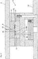
Fig. 2 is a longitudinal cross-sectional view of one example of an injection mold for manufacturing the ring-shaped insert molded article; -
Fig. 3 is an enlarged longitudinal cross-sectional view of major components of the injection mold; -
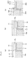
Fig. 4 is an enlarged longitudinal cross-sectional view of major components, showing one example of a metal mold structure (insert core-type):Fig. 4(a) shows a state in which, after mold clamping, a molten plastic is injected into the metal mold;Fig. 4(b) shows a state where the metal mold is cooled and then opened; andFig. 4(c) shows a state where the molded article is removed from the metal mold, set on a jig, and then cut at a gate; -
Fig. 5 is an enlarged longitudinal cross-sectional view of major components, showing one example of another metal mold structure (slide core-type):Fig. 5(a) shows a state in which, after mold clamping, a molten plastic is injected into the metal mold;Fig. 5(b) shows a state where the metal mold is cooled and then opened; andFig. 5(c) shows a state where the molded article is removed from the metal mold, set on a jig, and then cut at a gate; -
Fig. 6 is a longitudinal cross-sectional view of a ring-shaped insert molded article (radial magnetic encoder) obtained by a method according to a second embodiment of the present invention; -
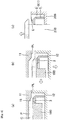
Fig. 7 is an enlarged longitudinal cross-sectional view of major components, showing one example of a metal mold structure (insert core-type):Fig. 7(a) shows a state in which, after mold clamping, a molten plastic is injected into the metal mold;Fig. 7(b) shows a state where the metal mold is cooled and then opened; andFig. 7(c) shows a state where the molded article is removed from the metal mold, set on a jig, and then cut at a gate; -
Fig. 8 is an enlarged longitudinal cross-sectional view of major components, showing one example of another metal mold structure (slide core-type):Fig. 8(a) shows a state in which, after mold clamping, a molten plastic is injected into the metal mold;Fig. 8(b) shows a state where the metal mold is cooled and then opened; andFig. 8(c) shows a state where the molded article is removed from the metal mold, set on a jig, and then cut at a gate. - The present invention is not limited to the embodiments shown in the drawings but includes all of embodiments meeting the requirements described in the patent claims.
- As shown in the longitudinal cross-sectional view of
Fig. 1 , a ring-shaped insert moldedarticle 1 obtained by a method according to a first embodiment of the present invention is manufactured by injection molding in a state where a thermoset adhesive is applied to a joining surface of a ring-shaped insert 2 to a plastic 4 and then the ring-shaped insert 2 and the plastic 4 are placed in a metal mold. Anadhesive layer 6 intervenes between the ring-shaped insert 2 and the plastic 4. - In addition, the ring-shaped insert molded
article 1 is an axial magnetic encoder A in which the ring-shaped insert 2 is a support member and the plastic 4 is a plastic magnet. - The
insert 2 is made of a steel plate and includes a cylindrical part 2A and anannular part 2B extended radially outward from one end edge of the cylindrical part 2A. The ring-shaped insert 2 is formed by pressing a stainless-steel plate of 0.6 mm thick, for example. - The shape of the ring-
shaped insert 2 is not limited to that shown inFig. 1 as far as it includes at least the cylindrical part 2A and theannular part 2B. - The plastic 4 is annular in shape so as to be joined to the
annular part 2B of the ring-shaped insert 2. Inner diameter D1 of the plastic 4 is larger than an inner diameter D2 of theannular part 2B (inner diameter of the cylindrical part 2A) (D1 > D2) so that no burrs at a gate mark E protrude to the inner diameter side of the moldedarticle 1. Radial distance G between an inner peripheral surface F of the plastic 4 and an inner peripheral surface of the ring-shaped insert 2 (inner peripheral surface of theannular part 2B) is 0.3 mm or more (G ≥ 0.3 mm). Thus, a difference between the inner diameter D1 of the plastic 4 and the inner diameter D2 of theannular part 2B is 0.6 mm or more (D1 - D2 ≥ 0.6 mm) and thickness T1 of the plastic 4 is 0.9 mm, for example. - In addition, the plastic 4 is formed by injection molding such that a disc gate described later is arranged on an inner peripheral surface F at a position separated from the surface of the
annular part 2B. In the gate-cut state, the gate mark E resides on the inner peripheral surface F of the plastic 4 at a position separated from the surface of theannular par 2B, and a distance L1 from the surface of theannular part 2B to the gate mark E is 0.1 mm or more (L1 ≥ 0.1 mm), so that no foreign matter resulting from gate cutting sticks to the surface and no shearing load is applied by gate cutting to the joining surface between the ring-shaped insert 2 and the plastic 4 to prevent degradation of adhesive performance as described later. - The plastic (plastic magnet) 4 is formed by a magnetic material containing magnetic substance powder, a binder, and an additive. The magnetic substance powder may be preferably magnetic powder based on ferrite such as strontium ferrite or barium ferrite, or rare-earth magnetic powder based on neodymium or samarium. The binder may be preferably a thermoplastic resin material such as polyamides (PA6, PA12, PA612, and the like) or polyphenylene sulfide (PPS). The additive may be preferably an organic additive such as carbon fiber, or an inorganic additive such as glass beads, glass fiber, talc, mica, silicon nitride (ceramic), or crystalline (non-crystalline) silica.
- Next, an example of injection molding for manufacturing the ring-shaped insert molded
article 1 according to the first embodiment of the present invention will be described. - As shown in the longitudinal cross-sectional view of
Fig. 2 and the enlarged longitudinal cross-sectional view of major components ofFig. 3 , aninjection mold 8 is intended to mold the ring-shaped insert molded article 1 (axial magnetic encoder A) and is attached to an injection molding machine by fixing afixed attachment plate 9 to a fixed platen with a bolt and fixing amovable attachment plate 10 to a movable disc with a bolt. - In a state where a thermoset adhesive is applied to the joining surface of the ring-
shaped insert 2 to the plastic 4 and then the ring-shaped insert 2 and the plastic 4 are placed in a fixedmold plate 11 and amovable mold plate 12 and then the mold plates are clamped, when a molten plastic P is poured into asprue 13, the molten plastic P flows through adisc gate 15 via arunner 14 and is filled into a cavity C between the fixedmold plate 11 and the movable mold plate 12 (refer also to the enlarged longitudinal cross-sectional view of major components ofFig. 4(a) ). - The direction of extension of the sprue 13 (in which the molten plastic P is poured) is horizontal.
- After the molten plastic P is cooled and hardened, as shown in the enlarged longitudinal cross-sectional view of major components of
Fig. 4(b) , themovable mold plate 12 is opened from a parting line PL and a pre-gate cutting molded article and aninsert core 18A are projected and ejected byejectors 16 and 17 (refer toFigs. 2 and3 ), thereby obtaining the pre-gate cutting molded article and theinsert core 18A. - Next, as shown in the enlarged longitudinal cross-sectional view of major components of
Fig. 4(c) , while the pre-gate cutting molded article and theinsert core 18A removed from the metal mold are set on ajig 20A, the molded article is pressurized by apusher 21A to cut the gate. Thus, the gate mark E remains on the ring-shaped insert molded article 1 (axial magnetic encoder A). - At the gate cutting as shown in
Fig. 4(c) , theinsert core 18A is placed along the gate cutting part of the plastic such that theinsert core 18A serves as a cutting blade to cut the gate by shearing action. This reduces load on the product at the time of gate cutting. - Next, an example of a metal mold structure different from the insert core type as shown in
Fig. 4 will be described. - The enlarged longitudinal cross-sectional view of major components of
Fig. 5 shows a slide core-type metal mold structure. - After the molten plastic P is filled into the cavity C and then is cooled and hardened as shown in
Fig. 5(a) , aslide core 19A is slid radially inward and separated from the molded article as shown inFig 5(b) . In this state, themovable mold plate 12 is opened from the parting line PL and a pre-gate cutting molded article is projected and ejected by the ejector 16 (refer toFig. 2 ). Thus, the pre-gate cutting molded article is obtained. - Next, as shown in
Fig. 5(c) , while the pre-gate cutting molded article removed from the metal mold is set on thejig 20A, the molded article is pressurized by thepusher 21A to cut the gate. The gate mark E remains on the ring-shaped insert molded article 1 (axial magnetic encoder A). - According to the configuration of the ring-shaped insert molded article 1 (axial magnetic encoder A) in the first embodiment, the inner diameter D1 of the annular plastic 4 is larger than the inner diameter D2 of the
annular part 2B of the ring-shapedinsert 2 so that no burrs at the gate mark E protrude to the inner diameter side of the moldedarticle 1, which thus eliminates the need for additional work to remove the burrs. - In addition, in the gate-cut state, the gate mark E resides on the inner peripheral surface F of the plastic 4 at a position separated from the surface of the
annular part 2B so that no foreign matter resulting from the gate cutting sticks to the surface and no shearing load is applied by gate cutting to the joining surface between the ring-shapedinsert 2 and the plastic 4 to prevent deterioration in adhesive performance. This eliminates the need to perform a post-process for removing the foreign matter because of absence of the foreign matter on the surface and prevents degradation of adhesive performance caused by the gate cutting. - In addition, in the case where the ring-shaped insert molded
article 1 is an axial magnetic encoder A in which the ring-shapedinsert 2 is a support member, the plastic 4 is a plastic magnet, the inner diameter D1 of the plastic 4 is 0.6 mm or more larger than the inner diameter D2 of theannular part 2B, and the gate mark E resides at a position separated 0.1 mm or more from the surface of theannular part 2B, and further in the case where the ring-shaped insert moldedarticle 1 is an axial magnetic encoder A, it is ensured that the additional work and post-process are not needed after the gate cutting and degradation of adhesive performance caused by the gate cutting is prevented. - As shown in the longitudinal cross-sectional view of
Fig. 6 , the ring-shaped insert moldedarticle 1 obtained by a method according to a second embodiment of the present invention is manufactured by injection molding in a state where a thermoset adhesive is applied to a joining surface of a ring-shapedinsert 3 to aplastic 5 and then the ring-shapedinsert 3 and theplastic 5 are placed in a metal mold, and theadhesive layer 6 intervenes between the ring-shapedinsert 3 and theplastic 5. - In addition, the ring-shaped insert molded
article 1 is a radial magnetic encoder B in which the ring-shapedinsert 3 is a support member and theplastic 5 is a plastic magnet. - The ring-shaped
insert 3 is made of a steel plate and includes a cylindrical part 3A and anannular part 3B extended radially inward from one end edge of the cylindrical part 3A. The ring-shapedinsert 3 is formed by pressing a stainless-steel plate of 0.6 mm thick, for example. - The shape of the ring-shaped
insert 3 is not limited to that shown inFig. 6 as far as it includes at least the cylindrical part 3A and theannular part 3B. - The material for the plastic (plastic magnet) 5 is the same as that in the first embodiment. The
plastic 5 is cylindrical in shape so as to be joined to the outer peripheral surface of the cylindrical part 3A of the ring-shapedinsert 3, and has a curve part 7 over theannular part 3B. Thickness T2 of theplastic 5 is 0.9 mm, for example. - In addition, the
plastic 5 is injection-molded such that a disc gate is arranged on the inner peripheral surface F at a position separated from the surface of theannular part 3B. In the gate-cut state, the gate mark E resides on the inner peripheral surface F of the plastic 5 at a position separated from the surface of theannular part 3B, and a distance L2 from the surface of theannular part 3B to the gate mark E is 0.1 mm or more (L2 ≥ 0.1 mm), so that no foreign matter resulting from gate cutting sticks to the surface and no shearing load is applied by gate cutting to the joining surface between the ring-shapedinsert 3 and the plastic 5 to prevent degradation of adhesive performance as described later. - Next, an example of injection molding for manufacturing the ring-shaped insert molded
article 1 according to the second embodiment of the present invention will be described. - The ring-shaped insert molded article 1 (radial magnetic encoder B) can be manufactured using the same metal mold as the
injection mold 8 shown inFig. 2 . After the molten plastic P is filled into the cavity C and then is cooled and hardened as shown in the enlarged longitudinal cross-sectional view of major components ofFig. 7(a) , themovable mold plate 12 is opened from the parting line PL and a pre-gate cutting molded article and aninsert core 18B are projected and ejected by theejectors 16 and 17 (refer toFig. 2 ), thereby obtaining the pre-gate cutting molded article and theinsert core 18B as shown in the enlarged longitudinal cross-sectional view of major components ofFig. 7(b) . - Next, as shown in the enlarged longitudinal cross-sectional view of major components of
Fig. 7(c) , while the pre-gate cutting molded article and theinsert core 18B removed from the metal mold are set on ajig 20B, the molded article is pressurized by apusher 21B to cut the gate. The gate mark E remains on the ring-shaped insert molded article 1 (radial magnetic encoder B). - At the gate cutting as shown in
Fig. 7(c) , theinsert core 18B is placed along the gate cutting part of the plastic such that theinsert core 18B serves as a cutting blade to cut the gate by shearing action. This reduces load on the product at the time of gate cutting. - Next, an example of a metal mold structure different from the insert core type shown in
Fig. 7 will be described. - The enlarged longitudinal cross-sectional view of major components of
Fig. 8 shows a slide core-type metal mold structure. - After the molten plastic P is filled into the cavity C and then is cooled and hardened as shown in
Fig. 8(a) , aslide core 19B is slid radially inward and separated from the molded article as shown inFig 8(b) . In this state, themovable mold plate 12 is opened from the parting line PL and a pre-gate cutting molded article is projected and ejected by the ejector 16 (refer toFig. 2 ). Thus, the pre-gate cutting molded article is obtained. - Next, as shown in
Fig. 8(c) , while the pre-gate cutting molded article removed from the metal mold is set on thejig 20B, the molded article is pressurized by thepusher 21B to cut the gate. The gate mark E remains on the ring-shaped insert molded article 1 (radial magnetic encoder B). - According to the configuration of the ring-shaped insert molded article 1 (radial magnetic encoder B) in the second embodiment, the inner diameter of the curve part 7 of the
cylindrical plastic 5 is sufficiently larger than the inner diameter of theannular part 3B of the ring-shapedinsert 3, and thus no burrs at the gate mark E protrude to the inner diameter side of the moldedarticle 1, which thus eliminates the need for additional work to remove the burrs. - In addition, in the gate-cut state, the gate mark E resides on the inner peripheral surface F of the plastic 5 at a position separated from the surface of the
annular part 3B so that no foreign matter resulting from the gate cutting sticks to the surface and no shearing load is applied by gate cutting to the joining surface between the ring-shapedinsert 3 and the plastic 5 to prevent deterioration in adhesive performance. This eliminates the need to perform a post-process for removing the foreign matter because of absence of the foreign matter on the surface and prevents degradation of adhesive performance caused by the gate cutting. - In addition, in the case where the ring-shaped insert molded
article 1 is a radial magnetic encoder B in which the ring-shapedinsert 3 is a support member, theplastic 5 is a plastic magnet, and the gate mark E resides at a position separated 0.1 mm or more from the surface of theannular part 3B, and further in the case where the ring-shaped insert moldedarticle 1 is a radial magnetic encoder B, it is ensured that the additional work and post-process are not needed after the gate cutting and degradation of adhesive performance caused by the gate cutting is prevented. - In the foregoing descriptions, the ring-shaped insert molded article is an axial magnetic encoder or a radial magnetic encoder. However, the ring-shaped insert molded article of the present invention is not limited to them but can be manufactured in any manner by injection molding in the state where a thermoset adhesive is applied to the joining surface of the ring-shaped insert to the plastic and then the insert and the plastic are placed in the metal mold, such as an insert molded article with replacement of a ring-shaped metal.
- In addition, the ring-shaped molded article of the present invention is configured such that, in the gate-cut state, the gate mark resides on the inner peripheral surface of the plastic at a position separated from the surface of the annular part so that no foreign matter resulting from the gate cutting sticks to the surface and no shearing load is applied by gate cutting to the joining surface between the insert and the plastic to prevent deterioration in adhesive performance. This eliminates the need to perform the post-process for removing the foreign matter because of absence of the foreign matter on the surface and prevents degradation of adhesive performance caused by the gate cutting. Besides, no burrs at the gate mark protrude to the inner diameter side of the molded article, which thus eliminates the need for additional work to remove the burrs. However, the process for removing the burrs may be performed on the ring-shaped insert molded article, depending on the specifications for the ring-shaped insert molded article.
-
- A Axial magnetic encoder
- B Radial magnetic encoder
- C Cavity
- D1 Inner diameter of plastic
- D2 Inner diameter of annular part
- E Gate mark
- F Inner peripheral surface of plastic
- G Radial distance between inner peripheral surface of plastic and inner peripheral surface of insert
- L1, L2 Distance from surface of annular part to gate mark
- P Molten plastic
- PL Parting line
- T1, T2 Thickness
- 1 Ring-shaped insert molded article
- 2, 3 Ring-shaped insert
- 2A, 3A Cylindrical part
- 2B, 3B Annular part
- 4, 5 Plastic
- 6 Adhesive layer
- 7 Curve part
- 8 Injection mold
- 9 Fixed attachment plate
- 10 Movable attachment plate
- 11 Fixed mold plate
- 12 Movable mold plate
- 13 Sprue
- 14 Runner
- 15 Disc gate
- 16, 17 Ejector
- 18A, 18B Insert core
- 19A, 19B Slide core
- 20A, 20B Jig
- 21A, 21B Pusher
Claims (6)
- A method of producing a ring-shaped insert molded article (1),
wherein the article includes a ring-shaped insert (2) made of a steel plate,
the insert (2) has a cylindrical part (2A) and an annular part (2B) extended radially outward from one end edge of the cylindrical part (2A),
a plastic (4) annular in shape is joined via a thermoset adhesive (6) to the annular part (2B) of the insert (2), and
the inner diameter (D1) of the plastic (4) is larger than the inner diameter (D2) of the annular part (2B),
the method comprising the steps of:applying a thermoset adhesive to the joining surface of the ring-shaped insert (2) to the plastic (4), placing the ring-shaped insert (2) to the plastic (4) in an injection mold (8), clamping the injection mold (8), and filling the molten plastic (P) from a disc gate (15) separated from a surface of the annular part (2B) with an insert core (18A) into a cavity (C) of the injection mold so as to conduct an injection molding,cooling and hardening the molten plastic (P) and removing the pre-gate cutting molded article and the insert core (18A) from the metal mold, andpressurizing the molded article by a pusher (21A) to cut the gate while the pre-gate cutting molded article and the insert core (18A) removed from the metal mold are set on a jig (20A),wherein the gate mark (E) resides on the inner peripheral surface (F) of the plastic (4) at a position separated from the surface of the annular part (2B) in the gate-cut state. - A method of producing a ring-shaped insert molded article (1),
wherein the article includes a ring-shaped insert (2) made of a steel plate,
the insert (2) has a cylindrical part (2A) and an annular part (2B) extended radially outward from one end edge of the cylindrical part (2A),
a plastic (4) annular in shape is joined via a thermoset adhesive (6) to the annular part (2B) of the insert (2), and
the inner diameter (D1) of the plastic (4) is larger than the inner diameter (D2) of the annular part (2B),
the method comprising the steps of:applying a thermoset adhesive to the joining surface of the ring-shaped insert (2) to the plastic (4), placing the ring-shaped insert (2) to the plastic (4) in an injection mold (8), clamping the injection mold (8), and filling the molten plastic (P) from a disc gate (15) separated from a surface of the annular part (2B) with a slide core (19A) into a cavity (C) of the injection mold so as to conduct an injection molding,cooling and hardening the molten plastic (P) and removing the pre-gate cutting molded article from the metal mold, andpressurizing the molded article by a pusher (21A) to cut the gate while the pre-gate cutting molded article removed from the metal mold is set on a jig (20A),wherein the gate mark (E) resides on the inner peripheral surface (F) of the plastic (4) at a position separated from the surface of the annular part (2B) in the gate-cut state. - The method of producing a ring-shaped insert molded article according to Claim 1 or 2, wherein
the ring-shaped insert molded article (1) is an axial magnetic encoder (A) in which the ring-shaped insert (2) is a support member and the plastic (4) is a plastic magnet,
the inner diameter (D1) of the plastic (4) is 0.6 mm or more larger than the inner diameter (D2) of the annular part (2B), and
the gate mark (E) resides at a position separated 0.1 mm or more from the surface of the annular part (2B). - A method of producing a ring-shaped insert molded article (1),
wherein the article includes a ring-shaped insert (3) made of a steel plate,
the insert (3) has a cylindrical part (3A) and an annular part (3B) extended radially inward from one end edge of the cylindrical part (3A),
a plastic (5) cylindrical in shape is joined via a thermoset adhesive (6) to an outer circumferential surface of the cylindrical part (3A) of the insert (3), and
the plastic (5) has a curve part (7) over the annular part (3B),
the method comprising steps of;
applying a thermoset adhesive to the joining surface of the ring-shaped insert (3) to the plastic (5), placing the ring-shaped insert (3) to the plastic (5) in an injection mold, clamping the injection mold (8), and filling the molten plastic (P) from a disc gate (15) separated from a surface of the annular part (3B) with an insert core (18B) into a cavity (C) of the injection mold so as to conduct an injection molding,
cooling and hardening the molten plastic (P) and removing the pre-gate cutting molded article and the insert core (18B) from the metal mold, and
pressurizing the molded article by a pusher (21B) to cut the gate while the pre-gate cutting molded article and the insert core (18B) removed from the metal mold are set on a jig (20B),
wherein the gate mark (E) resides on the inner peripheral surface (F) of the plastic (5) at a position separated from the surface of the annular part (3B) in the gate-cut state. - A method of producing a ring-shaped insert molded article (1),
wherein the article includes a ring-shaped insert (3) made of a steel plate,
the insert (3) has a cylindrical part (3A) and an annular part (3B) extended radially inward from one end edge of the cylindrical part (3A),
a plastic (5) cylindrical in shape is joined via a thermoset adhesive (6) to an outer circumferential surface of the cylindrical part (3A) of the insert (3), and
the plastic (5) has a curve part (7) over the annular part (3B),
the method comprising steps of;
applying a thermoset adhesive to the joining surface of the ring-shaped insert (3) to the plastic (5), placing the ring-shaped insert (3) to the plastic (5) in an injection mold, clamping the injection mold (8), and filling the molten plastic (P) from a disc gate (15) separated from a surface of the annular part (3B) with a slide core (19B) into a cavity (C) of the injection mold so as to conduct an injection molding,
cooling and hardening the molten plastic (P) and removing the pre-gate cutting molded article from the metal mold, and
pressurizing the molded article by a pusher (21B) to cut the gate while the pre-gate cutting molded article removed from the metal mold is set on a jig (20B),
wherein the gate mark (E) resides on the inner peripheral surface (F) of the plastic (5) at a position separated from the surface of the annular part (3B) in the gate-cut state. - The method of producing a ring-shaped insert molded article according to Claim 4 or 5, wherein
the ring-shaped insert molded article (1) is a radial magnetic encoder (B) in which the ring-shaped insert (3) is a support member and the plastic (5) is a plastic magnet, and
the gate mark (E) resides at a position separated 0.1 mm or more from the surface of the annular part (3B).
Applications Claiming Priority (1)
| Application Number | Priority Date | Filing Date | Title |
|---|---|---|---|
| JP2013251941A JP2015108573A (en) | 2013-12-05 | 2013-12-05 | Ring shape insert molding |
Publications (2)
| Publication Number | Publication Date |
|---|---|
| EP2881232A1 EP2881232A1 (en) | 2015-06-10 |
| EP2881232B1 true EP2881232B1 (en) | 2017-09-06 |
Family
ID=52146054
Family Applications (1)
| Application Number | Title | Priority Date | Filing Date |
|---|---|---|---|
| EP14194633.5A Active EP2881232B1 (en) | 2013-12-05 | 2014-11-25 | Method for producing ring-shaped insert molded articles |
Country Status (4)
| Country | Link |
|---|---|
| US (4) | US20150158216A1 (en) |
| EP (1) | EP2881232B1 (en) |
| JP (1) | JP2015108573A (en) |
| CN (1) | CN104690882B (en) |
Families Citing this family (6)
| Publication number | Priority date | Publication date | Assignee | Title |
|---|---|---|---|---|
| DE102015112527B4 (en) * | 2015-07-30 | 2018-11-29 | Lapmaster Wolters Gmbh | Apparatus and method for pouring a ring-shaped plastic frame into a recess of a rotor disk of a double-side processing machine |
| DE102015223978B4 (en) * | 2015-12-02 | 2021-06-02 | Schaeffler Technologies AG & Co. KG | Method of manufacturing an encoder |
| CN105500605B (en) * | 2016-01-25 | 2018-10-12 | 深圳市信维通信股份有限公司 | A kind of insert structure for injection molding |
| JP7135617B2 (en) | 2018-09-07 | 2022-09-13 | 中西金属工業株式会社 | Manufacturing method of magnetic encoder |
| JP7200075B2 (en) * | 2019-09-26 | 2023-01-06 | 住友理工株式会社 | VEHICLE RESIN MODULE AND METHOD OF PRODUCING VEHICLE RESIN MODULE |
| JP7736230B2 (en) * | 2021-02-08 | 2025-09-09 | 中西金属工業株式会社 | Insert molding and its manufacturing method |
Family Cites Families (28)
| Publication number | Priority date | Publication date | Assignee | Title |
|---|---|---|---|---|
| JPH0727833B2 (en) | 1986-08-26 | 1995-03-29 | 住友ベ−クライト株式会社 | Manufacturing method for plastic magnets |
| US4954308A (en) * | 1988-03-04 | 1990-09-04 | Citizen Watch Co., Ltd. | Resin encapsulating method |
| JP2908176B2 (en) * | 1993-05-18 | 1999-06-21 | 株式会社小糸製作所 | Synthetic resin laminated lens for vehicle lighting and molding method thereof |
| JPH0727833A (en) | 1993-07-14 | 1995-01-31 | Seiko Epson Corp | Test signal generator |
| IT1295465B1 (en) * | 1997-10-03 | 1999-05-12 | Skf Ind Spa | DEVICE FOR DETECTION OF THE RELATIVE ROTATIONAL SPEED BETWEEN THE RINGS OF A ROLLING BEARING. |
| JPH11284002A (en) * | 1998-03-31 | 1999-10-15 | Sumitomo Heavy Ind Ltd | Resin sealing device for semiconductor element |
| JP2000289405A (en) * | 1999-04-02 | 2000-10-17 | Nsk Ltd | Combination seal ring with encoder |
| US6517757B1 (en) * | 1999-12-03 | 2003-02-11 | The Plastic Moldings Corporation | Methods for molding a part around an insert |
| JP2002131082A (en) * | 2000-10-24 | 2002-05-09 | Uchiyama Mfg Corp | Manufacturing method of magnetic encoder |
| SG120053A1 (en) * | 2001-10-05 | 2006-03-28 | Advanced Systems Automation | Apparatus for molding a semiconductor wafer and process therefor |
| JP2004077318A (en) * | 2002-08-20 | 2004-03-11 | Uchiyama Mfg Corp | Magnetic encoder |
| JP3639827B2 (en) * | 2002-09-19 | 2005-04-20 | 三菱電機株式会社 | Motor system with optical encoder and optical encoder |
| USRE48526E1 (en) * | 2004-01-22 | 2021-04-20 | Nsk Ltd. | Magnetic encoder and bearing |
| JP2006133018A (en) * | 2004-11-04 | 2006-05-25 | Nsk Ltd | Magnetic encoder |
| JP2006313117A (en) * | 2005-05-09 | 2006-11-16 | Nsk Ltd | Encoder manufacturing method |
| JP4910316B2 (en) | 2005-06-21 | 2012-04-04 | 日本精工株式会社 | Magnetic encoder and rolling bearing unit including the magnetic encoder |
| US7671582B2 (en) * | 2005-05-10 | 2010-03-02 | Nsk Ltd. | Magnetic encoder and roller bearing unit having magnetic encoder |
| JP4682737B2 (en) * | 2005-05-23 | 2011-05-11 | 日本精工株式会社 | Encoder manufacturing method and rolling bearing device |
| JP2007010343A (en) * | 2005-06-28 | 2007-01-18 | Uchiyama Mfg Corp | Tone wheel manufacturing method |
| JP2008087356A (en) * | 2006-10-03 | 2008-04-17 | Towa Corp | Resin sealing molding method and apparatus for electronic parts |
| WO2008081586A1 (en) * | 2006-12-27 | 2008-07-10 | Ntn Corporation | Bearing unit for wheel |
| JP5036045B2 (en) * | 2007-07-18 | 2012-09-26 | 内山工業株式会社 | Magnetic encoder |
| JP2009265287A (en) * | 2008-04-24 | 2009-11-12 | Nippon Seiki Co Ltd | Reflecting mirror |
| JP5200654B2 (en) * | 2008-05-12 | 2013-06-05 | 日本精工株式会社 | Manufacturing method of slinger with encoder and rolling bearing unit with encoder |
| WO2010004696A1 (en) * | 2008-07-08 | 2010-01-14 | Ntn株式会社 | Sealing device with magnetic encoder, and wheel bearing device using the sealing device |
| JP2010249536A (en) * | 2009-04-10 | 2010-11-04 | Ntn Corp | Magnetic encoder and manufacturing method thereof |
| JP5568438B2 (en) | 2010-10-25 | 2014-08-06 | 株式会社ジェイテクト | Magnetized pulsar ring and rolling bearing device |
| JP5834751B2 (en) * | 2011-10-13 | 2015-12-24 | 株式会社ジェイテクト | Magnetized pulsar ring, manufacturing method thereof, and rolling bearing device |
-
2013
- 2013-12-05 JP JP2013251941A patent/JP2015108573A/en active Pending
-
2014
- 2014-11-17 US US14/543,083 patent/US20150158216A1/en not_active Abandoned
- 2014-11-25 EP EP14194633.5A patent/EP2881232B1/en active Active
- 2014-12-04 CN CN201410737149.8A patent/CN104690882B/en active Active
-
2016
- 2016-05-23 US US15/161,781 patent/US20160263793A1/en not_active Abandoned
-
2017
- 2017-01-23 US US15/412,209 patent/US9962877B2/en active Active
- 2017-01-23 US US15/412,213 patent/US9962876B2/en active Active
Non-Patent Citations (1)
| Title |
|---|
| None * |
Also Published As
| Publication number | Publication date |
|---|---|
| JP2015108573A (en) | 2015-06-11 |
| US20160263793A1 (en) | 2016-09-15 |
| US9962876B2 (en) | 2018-05-08 |
| US20170129149A1 (en) | 2017-05-11 |
| EP2881232A1 (en) | 2015-06-10 |
| US20170129151A1 (en) | 2017-05-11 |
| US20150158216A1 (en) | 2015-06-11 |
| CN104690882B (en) | 2018-07-17 |
| US9962877B2 (en) | 2018-05-08 |
| CN104690882A (en) | 2015-06-10 |
Similar Documents
| Publication | Publication Date | Title |
|---|---|---|
| US9962876B2 (en) | Ring-shaped insert molded article | |
| CN107206479B (en) | Casting moulds, inserts for casting moulds, castings and methods of casting the same | |
| US10821637B2 (en) | Resin injection apparatus and method of manufacturing core product | |
| CN108290328B (en) | Method for producing composite molded body | |
| JP5799606B2 (en) | Manufacturing method of rotor | |
| JP2015073406A (en) | Stator molding method and molding apparatus | |
| US20040151795A1 (en) | Cast secondary part for electric motors | |
| US20160346975A1 (en) | Injection molding die and manufacturing method of insert molded article | |
| JP2016037911A (en) | Impeller and injection mold equipment | |
| JP6597827B2 (en) | Manufacturing method of ring-shaped insert molded product | |
| CN106030735A (en) | Die casting molds for permanent magnets | |
| US10666120B2 (en) | Method for injecting resin into laminated iron core | |
| CN110884029B (en) | Method for manufacturing magnetic encoder | |
| JP2019081310A (en) | Cylindrical molded product manufacturing device | |
| JP6729872B2 (en) | Annular magnet manufacturing apparatus and annular magnet manufacturing method | |
| JP4255311B2 (en) | Method for producing resin molded body with cylindrical magnetic body | |
| JP2006264208A (en) | Injection-molding mold and injection-molding method for resin pulley | |
| JP2001246638A (en) | Injection molding method of multicolor molded article and rotor of PM type stepping motor | |
| JP2019072956A (en) | Molding die of resin molding | |
| EP4442443A1 (en) | Manufacturing device and forming method for rotary-component reinforcement carbon fiber reinforced plastic | |
| JP2022134726A (en) | Method for manufacturing molded article composed of metal part, resin part and thermosetting elastomer part | |
| JP2019072955A (en) | Method for manufacturing resin molding |
Legal Events
| Date | Code | Title | Description |
|---|---|---|---|
| PUAI | Public reference made under article 153(3) epc to a published international application that has entered the european phase |
Free format text: ORIGINAL CODE: 0009012 |
|
| 17P | Request for examination filed |
Effective date: 20141125 |
|
| AK | Designated contracting states |
Kind code of ref document: A1 Designated state(s): AL AT BE BG CH CY CZ DE DK EE ES FI FR GB GR HR HU IE IS IT LI LT LU LV MC MK MT NL NO PL PT RO RS SE SI SK SM TR |
|
| AX | Request for extension of the european patent |
Extension state: BA ME |
|
| R17P | Request for examination filed (corrected) |
Effective date: 20151209 |
|
| RBV | Designated contracting states (corrected) |
Designated state(s): AL AT BE BG CH CY CZ DE DK EE ES FI FR GB GR HR HU IE IS IT LI LT LU LV MC MK MT NL NO PL PT RO RS SE SI SK SM TR |
|
| 17Q | First examination report despatched |
Effective date: 20160727 |
|
| GRAP | Despatch of communication of intention to grant a patent |
Free format text: ORIGINAL CODE: EPIDOSNIGR1 |
|
| STAA | Information on the status of an ep patent application or granted ep patent |
Free format text: STATUS: GRANT OF PATENT IS INTENDED |
|
| RIC1 | Information provided on ipc code assigned before grant |
Ipc: B29C 45/38 20060101AFI20170127BHEP Ipc: B29C 45/14 20060101ALI20170127BHEP Ipc: G01D 5/00 20060101ALN20170127BHEP Ipc: B29C 45/27 20060101ALI20170127BHEP Ipc: B29K 105/16 20060101ALN20170127BHEP |
|
| INTG | Intention to grant announced |
Effective date: 20170223 |
|
| GRAS | Grant fee paid |
Free format text: ORIGINAL CODE: EPIDOSNIGR3 |
|
| GRAJ | Information related to disapproval of communication of intention to grant by the applicant or resumption of examination proceedings by the epo deleted |
Free format text: ORIGINAL CODE: EPIDOSDIGR1 |
|
| GRAL | Information related to payment of fee for publishing/printing deleted |
Free format text: ORIGINAL CODE: EPIDOSDIGR3 |
|
| STAA | Information on the status of an ep patent application or granted ep patent |
Free format text: STATUS: EXAMINATION IS IN PROGRESS |
|
| GRAR | Information related to intention to grant a patent recorded |
Free format text: ORIGINAL CODE: EPIDOSNIGR71 |
|
| STAA | Information on the status of an ep patent application or granted ep patent |
Free format text: STATUS: GRANT OF PATENT IS INTENDED |
|
| GRAA | (expected) grant |
Free format text: ORIGINAL CODE: 0009210 |
|
| STAA | Information on the status of an ep patent application or granted ep patent |
Free format text: STATUS: THE PATENT HAS BEEN GRANTED |
|
| RAP1 | Party data changed (applicant data changed or rights of an application transferred) |
Owner name: NAKANISHI METAL WORKS CO., LTD. |
|
| RIN1 | Information on inventor provided before grant (corrected) |
Inventor name: ITO, YOSHIHIRO Inventor name: OKA, NOBUMASA |
|
| INTC | Intention to grant announced (deleted) | ||
| RIC1 | Information provided on ipc code assigned before grant |
Ipc: G01D 5/00 20060101ALN20170720BHEP Ipc: B29C 45/27 20060101ALI20170720BHEP Ipc: B29C 45/14 20060101ALI20170720BHEP Ipc: B29K 105/16 20060101ALN20170720BHEP Ipc: B29C 45/38 20060101AFI20170720BHEP |
|
| AK | Designated contracting states |
Kind code of ref document: B1 Designated state(s): AL AT BE BG CH CY CZ DE DK EE ES FI FR GB GR HR HU IE IS IT LI LT LU LV MC MK MT NL NO PL PT RO RS SE SI SK SM TR |
|
| INTG | Intention to grant announced |
Effective date: 20170731 |
|
| REG | Reference to a national code |
Ref country code: GB Ref legal event code: FG4D |
|
| REG | Reference to a national code |
Ref country code: CH Ref legal event code: EP Ref country code: AT Ref legal event code: REF Ref document number: 925381 Country of ref document: AT Kind code of ref document: T Effective date: 20170915 |
|
| REG | Reference to a national code |
Ref country code: IE Ref legal event code: FG4D |
|
| REG | Reference to a national code |
Ref country code: DE Ref legal event code: R096 Ref document number: 602014014106 Country of ref document: DE |
|
| REG | Reference to a national code |
Ref country code: FR Ref legal event code: PLFP Year of fee payment: 4 |
|
| REG | Reference to a national code |
Ref country code: NL Ref legal event code: MP Effective date: 20170906 |
|
| REG | Reference to a national code |
Ref country code: LT Ref legal event code: MG4D |
|
| PG25 | Lapsed in a contracting state [announced via postgrant information from national office to epo] |
Ref country code: NO Free format text: LAPSE BECAUSE OF FAILURE TO SUBMIT A TRANSLATION OF THE DESCRIPTION OR TO PAY THE FEE WITHIN THE PRESCRIBED TIME-LIMIT Effective date: 20171206 Ref country code: FI Free format text: LAPSE BECAUSE OF FAILURE TO SUBMIT A TRANSLATION OF THE DESCRIPTION OR TO PAY THE FEE WITHIN THE PRESCRIBED TIME-LIMIT Effective date: 20170906 Ref country code: LT Free format text: LAPSE BECAUSE OF FAILURE TO SUBMIT A TRANSLATION OF THE DESCRIPTION OR TO PAY THE FEE WITHIN THE PRESCRIBED TIME-LIMIT Effective date: 20170906 Ref country code: SE Free format text: LAPSE BECAUSE OF FAILURE TO SUBMIT A TRANSLATION OF THE DESCRIPTION OR TO PAY THE FEE WITHIN THE PRESCRIBED TIME-LIMIT Effective date: 20170906 Ref country code: HR Free format text: LAPSE BECAUSE OF FAILURE TO SUBMIT A TRANSLATION OF THE DESCRIPTION OR TO PAY THE FEE WITHIN THE PRESCRIBED TIME-LIMIT Effective date: 20170906 |
|
| REG | Reference to a national code |
Ref country code: AT Ref legal event code: MK05 Ref document number: 925381 Country of ref document: AT Kind code of ref document: T Effective date: 20170906 |
|
| PG25 | Lapsed in a contracting state [announced via postgrant information from national office to epo] |
Ref country code: BG Free format text: LAPSE BECAUSE OF FAILURE TO SUBMIT A TRANSLATION OF THE DESCRIPTION OR TO PAY THE FEE WITHIN THE PRESCRIBED TIME-LIMIT Effective date: 20171206 Ref country code: RS Free format text: LAPSE BECAUSE OF FAILURE TO SUBMIT A TRANSLATION OF THE DESCRIPTION OR TO PAY THE FEE WITHIN THE PRESCRIBED TIME-LIMIT Effective date: 20170906 Ref country code: LV Free format text: LAPSE BECAUSE OF FAILURE TO SUBMIT A TRANSLATION OF THE DESCRIPTION OR TO PAY THE FEE WITHIN THE PRESCRIBED TIME-LIMIT Effective date: 20170906 Ref country code: ES Free format text: LAPSE BECAUSE OF FAILURE TO SUBMIT A TRANSLATION OF THE DESCRIPTION OR TO PAY THE FEE WITHIN THE PRESCRIBED TIME-LIMIT Effective date: 20170906 Ref country code: GR Free format text: LAPSE BECAUSE OF FAILURE TO SUBMIT A TRANSLATION OF THE DESCRIPTION OR TO PAY THE FEE WITHIN THE PRESCRIBED TIME-LIMIT Effective date: 20171207 |
|
| PG25 | Lapsed in a contracting state [announced via postgrant information from national office to epo] |
Ref country code: NL Free format text: LAPSE BECAUSE OF FAILURE TO SUBMIT A TRANSLATION OF THE DESCRIPTION OR TO PAY THE FEE WITHIN THE PRESCRIBED TIME-LIMIT Effective date: 20170906 |
|
| PG25 | Lapsed in a contracting state [announced via postgrant information from national office to epo] |
Ref country code: PL Free format text: LAPSE BECAUSE OF FAILURE TO SUBMIT A TRANSLATION OF THE DESCRIPTION OR TO PAY THE FEE WITHIN THE PRESCRIBED TIME-LIMIT Effective date: 20170906 Ref country code: CZ Free format text: LAPSE BECAUSE OF FAILURE TO SUBMIT A TRANSLATION OF THE DESCRIPTION OR TO PAY THE FEE WITHIN THE PRESCRIBED TIME-LIMIT Effective date: 20170906 Ref country code: RO Free format text: LAPSE BECAUSE OF FAILURE TO SUBMIT A TRANSLATION OF THE DESCRIPTION OR TO PAY THE FEE WITHIN THE PRESCRIBED TIME-LIMIT Effective date: 20170906 |
|
| PG25 | Lapsed in a contracting state [announced via postgrant information from national office to epo] |
Ref country code: SM Free format text: LAPSE BECAUSE OF FAILURE TO SUBMIT A TRANSLATION OF THE DESCRIPTION OR TO PAY THE FEE WITHIN THE PRESCRIBED TIME-LIMIT Effective date: 20170906 Ref country code: AT Free format text: LAPSE BECAUSE OF FAILURE TO SUBMIT A TRANSLATION OF THE DESCRIPTION OR TO PAY THE FEE WITHIN THE PRESCRIBED TIME-LIMIT Effective date: 20170906 Ref country code: IS Free format text: LAPSE BECAUSE OF FAILURE TO SUBMIT A TRANSLATION OF THE DESCRIPTION OR TO PAY THE FEE WITHIN THE PRESCRIBED TIME-LIMIT Effective date: 20180106 Ref country code: SK Free format text: LAPSE BECAUSE OF FAILURE TO SUBMIT A TRANSLATION OF THE DESCRIPTION OR TO PAY THE FEE WITHIN THE PRESCRIBED TIME-LIMIT Effective date: 20170906 Ref country code: EE Free format text: LAPSE BECAUSE OF FAILURE TO SUBMIT A TRANSLATION OF THE DESCRIPTION OR TO PAY THE FEE WITHIN THE PRESCRIBED TIME-LIMIT Effective date: 20170906 |
|
| REG | Reference to a national code |
Ref country code: DE Ref legal event code: R097 Ref document number: 602014014106 Country of ref document: DE |
|
| PG25 | Lapsed in a contracting state [announced via postgrant information from national office to epo] |
Ref country code: MC Free format text: LAPSE BECAUSE OF FAILURE TO SUBMIT A TRANSLATION OF THE DESCRIPTION OR TO PAY THE FEE WITHIN THE PRESCRIBED TIME-LIMIT Effective date: 20170906 |
|
| PLBE | No opposition filed within time limit |
Free format text: ORIGINAL CODE: 0009261 |
|
| STAA | Information on the status of an ep patent application or granted ep patent |
Free format text: STATUS: NO OPPOSITION FILED WITHIN TIME LIMIT |
|
| PG25 | Lapsed in a contracting state [announced via postgrant information from national office to epo] |
Ref country code: LI Free format text: LAPSE BECAUSE OF NON-PAYMENT OF DUE FEES Effective date: 20171130 Ref country code: DK Free format text: LAPSE BECAUSE OF FAILURE TO SUBMIT A TRANSLATION OF THE DESCRIPTION OR TO PAY THE FEE WITHIN THE PRESCRIBED TIME-LIMIT Effective date: 20170906 Ref country code: CH Free format text: LAPSE BECAUSE OF NON-PAYMENT OF DUE FEES Effective date: 20171130 |
|
| 26N | No opposition filed |
Effective date: 20180607 |
|
| PG25 | Lapsed in a contracting state [announced via postgrant information from national office to epo] |
Ref country code: LU Free format text: LAPSE BECAUSE OF NON-PAYMENT OF DUE FEES Effective date: 20171125 Ref country code: SI Free format text: LAPSE BECAUSE OF FAILURE TO SUBMIT A TRANSLATION OF THE DESCRIPTION OR TO PAY THE FEE WITHIN THE PRESCRIBED TIME-LIMIT Effective date: 20170906 |
|
| REG | Reference to a national code |
Ref country code: BE Ref legal event code: MM Effective date: 20171130 |
|
| REG | Reference to a national code |
Ref country code: IE Ref legal event code: MM4A |
|
| PG25 | Lapsed in a contracting state [announced via postgrant information from national office to epo] |
Ref country code: MT Free format text: LAPSE BECAUSE OF NON-PAYMENT OF DUE FEES Effective date: 20171125 |
|
| PG25 | Lapsed in a contracting state [announced via postgrant information from national office to epo] |
Ref country code: IE Free format text: LAPSE BECAUSE OF NON-PAYMENT OF DUE FEES Effective date: 20171125 |
|
| PG25 | Lapsed in a contracting state [announced via postgrant information from national office to epo] |
Ref country code: BE Free format text: LAPSE BECAUSE OF NON-PAYMENT OF DUE FEES Effective date: 20171130 |
|
| PG25 | Lapsed in a contracting state [announced via postgrant information from national office to epo] |
Ref country code: HU Free format text: LAPSE BECAUSE OF FAILURE TO SUBMIT A TRANSLATION OF THE DESCRIPTION OR TO PAY THE FEE WITHIN THE PRESCRIBED TIME-LIMIT; INVALID AB INITIO Effective date: 20141125 |
|
| GBPC | Gb: european patent ceased through non-payment of renewal fee |
Effective date: 20181125 |
|
| PG25 | Lapsed in a contracting state [announced via postgrant information from national office to epo] |
Ref country code: CY Free format text: LAPSE BECAUSE OF FAILURE TO SUBMIT A TRANSLATION OF THE DESCRIPTION OR TO PAY THE FEE WITHIN THE PRESCRIBED TIME-LIMIT Effective date: 20170906 |
|
| PG25 | Lapsed in a contracting state [announced via postgrant information from national office to epo] |
Ref country code: MK Free format text: LAPSE BECAUSE OF FAILURE TO SUBMIT A TRANSLATION OF THE DESCRIPTION OR TO PAY THE FEE WITHIN THE PRESCRIBED TIME-LIMIT Effective date: 20170906 |
|
| PG25 | Lapsed in a contracting state [announced via postgrant information from national office to epo] |
Ref country code: GB Free format text: LAPSE BECAUSE OF NON-PAYMENT OF DUE FEES Effective date: 20181125 |
|
| PG25 | Lapsed in a contracting state [announced via postgrant information from national office to epo] |
Ref country code: TR Free format text: LAPSE BECAUSE OF FAILURE TO SUBMIT A TRANSLATION OF THE DESCRIPTION OR TO PAY THE FEE WITHIN THE PRESCRIBED TIME-LIMIT Effective date: 20170906 |
|
| PG25 | Lapsed in a contracting state [announced via postgrant information from national office to epo] |
Ref country code: PT Free format text: LAPSE BECAUSE OF FAILURE TO SUBMIT A TRANSLATION OF THE DESCRIPTION OR TO PAY THE FEE WITHIN THE PRESCRIBED TIME-LIMIT Effective date: 20170906 |
|
| PG25 | Lapsed in a contracting state [announced via postgrant information from national office to epo] |
Ref country code: AL Free format text: LAPSE BECAUSE OF FAILURE TO SUBMIT A TRANSLATION OF THE DESCRIPTION OR TO PAY THE FEE WITHIN THE PRESCRIBED TIME-LIMIT Effective date: 20170906 |
|
| PGFP | Annual fee paid to national office [announced via postgrant information from national office to epo] |
Ref country code: DE Payment date: 20251128 Year of fee payment: 12 |
|
| PGFP | Annual fee paid to national office [announced via postgrant information from national office to epo] |
Ref country code: IT Payment date: 20251107 Year of fee payment: 12 |
|
| PGFP | Annual fee paid to national office [announced via postgrant information from national office to epo] |
Ref country code: FR Payment date: 20251014 Year of fee payment: 12 |