EP2881214B1 - Tube cutting-off machine - Google Patents
Tube cutting-off machine Download PDFInfo
- Publication number
- EP2881214B1 EP2881214B1 EP14193503.1A EP14193503A EP2881214B1 EP 2881214 B1 EP2881214 B1 EP 2881214B1 EP 14193503 A EP14193503 A EP 14193503A EP 2881214 B1 EP2881214 B1 EP 2881214B1
- Authority
- EP
- European Patent Office
- Prior art keywords
- tube
- cutting
- length
- longitudinal axis
- cutting unit
- Prior art date
- Legal status (The legal status is an assumption and is not a legal conclusion. Google has not performed a legal analysis and makes no representation as to the accuracy of the status listed.)
- Active
Links
Images



Classifications
-
- B—PERFORMING OPERATIONS; TRANSPORTING
- B23—MACHINE TOOLS; METAL-WORKING NOT OTHERWISE PROVIDED FOR
- B23D—PLANING; SLOTTING; SHEARING; BROACHING; SAWING; FILING; SCRAPING; LIKE OPERATIONS FOR WORKING METAL BY REMOVING MATERIAL, NOT OTHERWISE PROVIDED FOR
- B23D21/00—Machines or devices for shearing or cutting tubes
- B23D21/04—Tube-severing machines with rotating tool-carrier
-
- B—PERFORMING OPERATIONS; TRANSPORTING
- B21—MECHANICAL METAL-WORKING WITHOUT ESSENTIALLY REMOVING MATERIAL; PUNCHING METAL
- B21C—MANUFACTURE OF METAL SHEETS, WIRE, RODS, TUBES, PROFILES OR LIKE SEMI-MANUFACTURED PRODUCTS OTHERWISE THAN BY ROLLING; AUXILIARY OPERATIONS USED IN CONNECTION WITH METAL-WORKING WITHOUT ESSENTIALLY REMOVING MATERIAL
- B21C37/00—Manufacture of metal sheets, rods, wire, tubes, profiles or like semi-manufactured products, not otherwise provided for; Manufacture of tubes of special shape
- B21C37/06—Manufacture of metal sheets, rods, wire, tubes, profiles or like semi-manufactured products, not otherwise provided for; Manufacture of tubes of special shape of tubes or metal hoses; Combined procedures for making tubes, e.g. for making multi-wall tubes
- B21C37/08—Making tubes with welded or soldered seams
- B21C37/0807—Tube treating or manipulating combined with, or specially adapted for use in connection with tube making machines, e.g. drawing-off devices, cutting-off
-
- B—PERFORMING OPERATIONS; TRANSPORTING
- B21—MECHANICAL METAL-WORKING WITHOUT ESSENTIALLY REMOVING MATERIAL; PUNCHING METAL
- B21C—MANUFACTURE OF METAL SHEETS, WIRE, RODS, TUBES, PROFILES OR LIKE SEMI-MANUFACTURED PRODUCTS OTHERWISE THAN BY ROLLING; AUXILIARY OPERATIONS USED IN CONNECTION WITH METAL-WORKING WITHOUT ESSENTIALLY REMOVING MATERIAL
- B21C37/00—Manufacture of metal sheets, rods, wire, tubes, profiles or like semi-manufactured products, not otherwise provided for; Manufacture of tubes of special shape
- B21C37/06—Manufacture of metal sheets, rods, wire, tubes, profiles or like semi-manufactured products, not otherwise provided for; Manufacture of tubes of special shape of tubes or metal hoses; Combined procedures for making tubes, e.g. for making multi-wall tubes
- B21C37/08—Making tubes with welded or soldered seams
- B21C37/0807—Tube treating or manipulating combined with, or specially adapted for use in connection with tube making machines, e.g. drawing-off devices, cutting-off
- B21C37/0811—Tube treating or manipulating combined with, or specially adapted for use in connection with tube making machines, e.g. drawing-off devices, cutting-off removing or treating the weld bead
-
- B—PERFORMING OPERATIONS; TRANSPORTING
- B23—MACHINE TOOLS; METAL-WORKING NOT OTHERWISE PROVIDED FOR
- B23D—PLANING; SLOTTING; SHEARING; BROACHING; SAWING; FILING; SCRAPING; LIKE OPERATIONS FOR WORKING METAL BY REMOVING MATERIAL, NOT OTHERWISE PROVIDED FOR
- B23D25/00—Machines or arrangements for shearing stock while the latter is travelling otherwise than in the direction of the cut
- B23D25/02—Flying shearing machines
- B23D25/04—Flying shearing machines in which a cutting unit moves bodily with the work while cutting
-
- B—PERFORMING OPERATIONS; TRANSPORTING
- B23—MACHINE TOOLS; METAL-WORKING NOT OTHERWISE PROVIDED FOR
- B23D—PLANING; SLOTTING; SHEARING; BROACHING; SAWING; FILING; SCRAPING; LIKE OPERATIONS FOR WORKING METAL BY REMOVING MATERIAL, NOT OTHERWISE PROVIDED FOR
- B23D79/00—Methods, machines, or devices not covered elsewhere, for working metal by removal of material
- B23D79/02—Machines or devices for scraping
- B23D79/021—Machines or devices for scraping for removing welding, brazing or soldering burrs, e.g. flash, on pipes or rods
- B23D79/023—Machines or devices for scraping for removing welding, brazing or soldering burrs, e.g. flash, on pipes or rods internally
-
- B—PERFORMING OPERATIONS; TRANSPORTING
- B23—MACHINE TOOLS; METAL-WORKING NOT OTHERWISE PROVIDED FOR
- B23K—SOLDERING OR UNSOLDERING; WELDING; CLADDING OR PLATING BY SOLDERING OR WELDING; CUTTING BY APPLYING HEAT LOCALLY, e.g. FLAME CUTTING; WORKING BY LASER BEAM
- B23K26/00—Working by laser beam, e.g. welding, cutting or boring
- B23K26/08—Devices involving relative movement between laser beam and workpiece
- B23K26/083—Devices involving movement of the workpiece in at least one axial direction
- B23K26/0838—Devices involving movement of the workpiece in at least one axial direction by using an endless conveyor belt
- B23K26/0846—Devices involving movement of the workpiece in at least one axial direction by using an endless conveyor belt for moving elongated workpieces longitudinally, e.g. wire or strip material
-
- B—PERFORMING OPERATIONS; TRANSPORTING
- B23—MACHINE TOOLS; METAL-WORKING NOT OTHERWISE PROVIDED FOR
- B23K—SOLDERING OR UNSOLDERING; WELDING; CLADDING OR PLATING BY SOLDERING OR WELDING; CUTTING BY APPLYING HEAT LOCALLY, e.g. FLAME CUTTING; WORKING BY LASER BEAM
- B23K26/00—Working by laser beam, e.g. welding, cutting or boring
- B23K26/08—Devices involving relative movement between laser beam and workpiece
- B23K26/10—Devices involving relative movement between laser beam and workpiece using a fixed support, i.e. involving moving the laser beam
- B23K26/103—Devices involving relative movement between laser beam and workpiece using a fixed support, i.e. involving moving the laser beam the laser beam rotating around the fixed workpiece
-
- B—PERFORMING OPERATIONS; TRANSPORTING
- B23—MACHINE TOOLS; METAL-WORKING NOT OTHERWISE PROVIDED FOR
- B23K—SOLDERING OR UNSOLDERING; WELDING; CLADDING OR PLATING BY SOLDERING OR WELDING; CUTTING BY APPLYING HEAT LOCALLY, e.g. FLAME CUTTING; WORKING BY LASER BEAM
- B23K26/00—Working by laser beam, e.g. welding, cutting or boring
- B23K26/36—Removing material
- B23K26/38—Removing material by boring or cutting
-
- B—PERFORMING OPERATIONS; TRANSPORTING
- B23—MACHINE TOOLS; METAL-WORKING NOT OTHERWISE PROVIDED FOR
- B23K—SOLDERING OR UNSOLDERING; WELDING; CLADDING OR PLATING BY SOLDERING OR WELDING; CUTTING BY APPLYING HEAT LOCALLY, e.g. FLAME CUTTING; WORKING BY LASER BEAM
- B23K31/00—Processes relevant to this subclass, specially adapted for particular articles or purposes, but not covered by any single one of main groups B23K1/00 - B23K28/00
- B23K31/02—Processes relevant to this subclass, specially adapted for particular articles or purposes, but not covered by any single one of main groups B23K1/00 - B23K28/00 relating to soldering or welding
- B23K31/027—Making tubes by soldering or welding
-
- B—PERFORMING OPERATIONS; TRANSPORTING
- B23—MACHINE TOOLS; METAL-WORKING NOT OTHERWISE PROVIDED FOR
- B23K—SOLDERING OR UNSOLDERING; WELDING; CLADDING OR PLATING BY SOLDERING OR WELDING; CUTTING BY APPLYING HEAT LOCALLY, e.g. FLAME CUTTING; WORKING BY LASER BEAM
- B23K2101/00—Articles made by soldering, welding or cutting
- B23K2101/04—Tubular or hollow articles
- B23K2101/06—Tubes
-
- Y—GENERAL TAGGING OF NEW TECHNOLOGICAL DEVELOPMENTS; GENERAL TAGGING OF CROSS-SECTIONAL TECHNOLOGIES SPANNING OVER SEVERAL SECTIONS OF THE IPC; TECHNICAL SUBJECTS COVERED BY FORMER USPC CROSS-REFERENCE ART COLLECTIONS [XRACs] AND DIGESTS
- Y10—TECHNICAL SUBJECTS COVERED BY FORMER USPC
- Y10T—TECHNICAL SUBJECTS COVERED BY FORMER US CLASSIFICATION
- Y10T82/00—Turning
- Y10T82/16—Severing or cut-off
-
- Y—GENERAL TAGGING OF NEW TECHNOLOGICAL DEVELOPMENTS; GENERAL TAGGING OF CROSS-SECTIONAL TECHNOLOGIES SPANNING OVER SEVERAL SECTIONS OF THE IPC; TECHNICAL SUBJECTS COVERED BY FORMER USPC CROSS-REFERENCE ART COLLECTIONS [XRACs] AND DIGESTS
- Y10—TECHNICAL SUBJECTS COVERED BY FORMER USPC
- Y10T—TECHNICAL SUBJECTS COVERED BY FORMER US CLASSIFICATION
- Y10T83/00—Cutting
- Y10T83/04—Processes
- Y10T83/0524—Plural cutting steps
-
- Y—GENERAL TAGGING OF NEW TECHNOLOGICAL DEVELOPMENTS; GENERAL TAGGING OF CROSS-SECTIONAL TECHNOLOGIES SPANNING OVER SEVERAL SECTIONS OF THE IPC; TECHNICAL SUBJECTS COVERED BY FORMER USPC CROSS-REFERENCE ART COLLECTIONS [XRACs] AND DIGESTS
- Y10—TECHNICAL SUBJECTS COVERED BY FORMER USPC
- Y10T—TECHNICAL SUBJECTS COVERED BY FORMER US CLASSIFICATION
- Y10T83/00—Cutting
- Y10T83/647—With means to convey work relative to tool station
- Y10T83/6476—Including means to move work from one tool station to another
Definitions
- the present invention relates to a cutting-off machine according to the preamble of claim 1, in particular a machine adapted to cutting a continuous tube into lengths of tube, wherein the continuous tube is realised by means of longitudinal welding of a bent metal sheet and a method for cutting off a tube.
- a machine is known from document US A 084 463 A while the prior art method is known from document EP 0 384 721 A .
- the inner seam is also removed immediately downstream of the longitudinal welding of the continuous tube and forms a continuous seam which is trapped inside the tube, also subsequent to cutting of said tube.
- Cutting of the continuous tube is, in fact; realised with special cutting-off machines (for example, orbital cutting machines), the cutting tools of which remain on the periphery of the tube and do not damage the continuous inner seam.
- the aforementioned inner seam which is continuous, does not allow correct offloading of the cut tubes, so it must be cut off.
- a cutting blade is activated which cuts the seam.
- barrier photocells positioned both before and after the seam cutting blade.
- the photocells upstream serve not to enable movement of the blade if the tube is too close to the cutting-off zone and therefore avoid impacts.
- the safety photocells are necessary since the tube is no longer on the cutting-off machine and, due to sliding/swaying of the tube on the roller bed, it is no longer possible to know precisely the position of the various tubes present on said roller bed.
- the length of the exposed section of the continuous inner seam at the moment of cutting depends on the distance travelled by the cut tube which is advancing on the roller bed and said distance, which cannot be controlled as the movement of the tube on the roller bed cannot be controlled, may also be considerable. Consequently, cutting of the seam may produce very long overhanging seam ends, which could accidentally become trapped between the rollers of the roller bed, slow down the tube to be offloaded, send false signals to the photocells, damage cables/tubes present on the machine and cause other related problems.
- the photocell signals are not always reliable due to fumes, dirt, swaying movements of the tubes and other related causes. This may lead to non-functioning of the cutting blade or non-optimal or irregular functioning, and consequently non-separation of the seam.
- the object of the present invention is therefore to provide a cutting-off machine which obviates the drawbacks of the prior art as cited above.
- an object of the present invention is to provide a cutting-off machine which is highly reliable and safe.
- the specified object is full achieved by a cutting-off machine according to the present invention as defined by claim 1, and a method according to claim 9.
- cutting-off is intended as the complete separation of a length of continuous tube or one much longer than said length. Said cutting-off is the sum of a first cutting operation, performed on the tube to separate the tube length, and a subsequent cutting operation of the floating inner seam (i.e. free as previously separated from the tube by means of a special inner detaching tool) inside the tube.
- the invention is aimed at cutting tubes of any cross-section, obtained by means of welding a metal sheet along a longitudinal welding line, and operates preferably downstream of a removal unit of the outer welding seam.
- Figure 1 shows a cutting-off machine according to the present invention, which is adapted to operate the cut of a tube 100 which is made to advance along its own longitudinal axis "X" according to a direction of advance "A", for example by means of a roller bed or other guide means and support adapted to the purpose.
- the rollers rotate around respective horizontal axes and have a double-cone shape ("hour-glass" shape), with reduced central diameter to realise a support and guide of the tube 100.
- the cutting-off machine 1 comprises, in the first place, a cutting unit 1 adapted to receive a tube 100 and to cut the tube 100 on a transversal or perpendicular plane to the longitudinal axis "X" of the tube 100, in particular on a vertical plane, in order to obtain a length "S" of tube separate from the remaining part of the tube 100.
- the cutting unit 2 is the orbital cutting type, i.e. having at least one or more cutting tools (not shown as known in themselves) mobile along a circular trajectory or curve which extends around the longitudinal axis "X" of the tube 100.
- Figures 1-5 show, in an entirely exemplary and diagrammatic way, two opposing tools 3 in the shape of circular blades, equipped with a rotary movement of revolution around the longitudinal axis "X" of the tube 100 and approach and radial distancing with respect to the tube 100. It is nonetheless possible to use other cutting tools, such as laser, water, plasma, etc., cutting heads.
- the cutting unit 2 cuts the tube 100 along a cutting line resting on a vertical plane, preferably perpendicular, to the longitudinal axis "X" of the tube 100. Said plane is preferably vertical.
- the cutting unit 2 is mobile along a parallel direction to the longitudinal axis "X" of the tube 100 to operate with a technique of following the tube 100.
- the cutting unit 2 is mobile in a sliding way (for example on a trolley 4 or another structure adapted to the purpose) parallel to the longitudinal axis "X" of the tube advancing parallel to said advance direction "A" of the tube 100 and backwards according to an opposite direction "R".
- the cutting unit 2 may move at the same advance speed of the tube 100 for a time at least sufficient to complete cutting of the tube 100 and, subsequently, may be brought backwards to operate a new cut on a subsequent part of the tube 100.
- the above may be summarised by stating that the cutting unit 2 is mobile in a sliding way forwards and backwards between a first position, more upstream with respect to the advance direction "A" and visible, for example, in figure 1 , with which a starting position of cutting of the tube 100 corresponds, and a second position, more downstream with respect to the advance direction "A" and visible, for example, in figure 4 , with which a completed cutting position of the tube 100 corresponds.
- the operations necessary to complete cutting of the tube 100 will be described below in more detail.
- a cutting-off device 5 is arranged, configured to cut the inner welding seam 200 floating inside the tube 100 and which is partially exposed after one length "S" of tube, separated from the remaining part of the tube 100, is distanced from said remaining part of the tube 100 by means of acceleration of the length "S".
- the cutting-off device 5 comprises a blade 6 mobile according to a respective transversal plane, preferably perpendicular, to the longitudinal axis "X" of the tube 100 under the action of an actuator 7.
- the blade 6 acts on a respective vertical plane according to a guillotine movement.
- the cutting-off device 5 is also mobile along a parallel direction to the longitudinal axis "X" of the tube 100 to operate with a technique of following on the tube 100.
- the cutting-off device 5 is mobile in a sliding way parallel to the longitudinal axis "X" of the tube 100 advancing parallel to said advance direction "A" of the tube 100 and backwards according to an opposite direction "R".
- the cutting-off device 5 may move at the same advance speed as the tube 100 for a time at least sufficient to complete cutting of the inner seam 200 and, subsequently, may be brought backwards to operate a new cut on a subsequent part of the inner seam 200.
- the above may be summarised by stating that the cutting-off device 2 is mobile in a sliding way forwards and backwards between a first position, more upstream with respect to the advance direction "A" and visible, for example, in figure 1 , with which a starting position of cutting of the tube 100 corresponds, and a second position, more downstream with respect to the advance direction "A" and visible, for example, in figure 4 , with which a completed cutting position of the tube 100 corresponds.
- the cutting unit 2 and the cutting-off device 5 are solidly joined in the forward/backward movement "A", "R” along the longitudinal axis "X" of the tube 100.
- the cutting unit 2 and the cutting-off device 5 may be arranged on the same trolley 4 which moves forwards and backwards along the longitudinal axis "X" of the tube 100 between said first and second position.
- the cutting-off machine 1 further comprises movement means 8 adapted to grip stably a length "S" of tube 100 previously cut and to distance the length "S” from the cutting unit 2 along an advance direction "A" of the tube 100.
- the movement means 8 grip the length "S” of the tube 100 just cut by the cutting unit 2 and accelerate it along an advance direction "A", so as to distance the length "S” from the remaining part of the tube 100, thus exposing a section of the inner seam 200 ( figure 3 ).
- the movement means 8 comprise a grip 9, preferably a roller grip, mounted sliding on a respective trolley 10 mobile forwards and backwards along the longitudinal axis "X" of the tube 100.
- the movement means 8 could be realised in another way, provided they are adapted to the purpose of gripping the length "S” and distancing it from the remaining portion of the tube 100 to expose a section of the inner seam 200.
- the movement means 8 are mobile in a sliding way forwards and backwards between a first position, more upstream with respect to the advance direction "A" and visible, for example, in figure 1 , with which a starting position of cutting of the tube 100 corresponds, and a second position, more downstream with respect to the advance direction "A" and visible, for example, in figure 4 , with which a completed cutting position of the tube 100 corresponds.
- the distance between the end positions assumed by the movement means 8 is greater than the distance between the end positions reached by the cutting unit 2 and by the cutting-off device 5.
- the movement means 8 have a travel, along the longitudinal axis "X" of the tube, which is greater with respect to the cutting unit 2 and the cutting-off device 5.
- the cutting-off device 5 is interposed between the cutting unit 2 and the movement means 8.
- the cutting-off device 5 is precisely at the section of the inner seam 200 exposed following the distancing action exerted by the movement means 8 on the length "S" just cut.
- the cutting-off machine 1 further comprises a control unit (not shown) configured to manage operation of the different parts of the cutting-off machine 1.
- control unit is configured to activate initially the cutting unit 2 on reaching a predetermined position of the tube along the longitudinal axis "X".
- the cutting unit 2 is activated both by activating translation of the trolley 4 and by activating, immediately or subsequently, the cutting tools 3 ( figure 2 ).
- control unit is configured to perform the following operations in succession, after completion of cutting of the length "S" by the cutting unit 2:
- activation of the movement means 8 to grip stably the length "S" after completion of cutting of the length "S” by the cutting unit 2 may be substituted by activation of movement means 8 to grip stably a front portion of the tube 100 before cutting of the length "S” by the cutting unit 2.
- the movement means 8 grip the tube 100 in its portion which will form the length "S" at the end of cutting and gripping remains stable until cutting of the inner seam 200.
- control unit sets an advance of the movement means 8 for a sufficient travel to allow a rear edge of the length "S" to overtake the cutting-off device 5 (and, in particular, to overtake the plane on which the blade 6 acts, which will therefore be positioned above the section of the inner seam 200 exposed). Subsequently to the moment when the rear edge of the length "S" overtakes the cutting-off device 5, the control unit maintains the movement means 8 at the same speed as the tube 100 or may continue to distance the length "S".
- the movement means 8 (or alternatively further means not shown) conduct the length "S" (having inside it a length of the inner seam 200) towards a receiving station which sorts the length "S” or alternatively submits the length "S" to further processing.
- the present invention achieves the proposed objects, overcoming the disadvantages complained in the known art.
- Configuration of the machine according to the invention allows, in fact, complete cutting of the tube (cutting of the length and subsequent cutting of the inner seam) in absolute safety and precision, since the movement means determine, at every moment and in a controlled way (for example by means of an advance curve imposed by the control unit) the position assumed by the length just cut. It is therefore possible to activate the cutting-off device on reaching an optimal configuration, particularly at the moment when the length has reached a safe distance from the tube and from the cutting-off device.
Landscapes
- Engineering & Computer Science (AREA)
- Mechanical Engineering (AREA)
- Physics & Mathematics (AREA)
- Optics & Photonics (AREA)
- Plasma & Fusion (AREA)
- Shearing Machines (AREA)
- Confectionery (AREA)
- Control And Other Processes For Unpacking Of Materials (AREA)
- Apparatuses For Bulk Treatment Of Fruits And Vegetables And Apparatuses For Preparing Feeds (AREA)
- Butt Welding And Welding Of Specific Article (AREA)
- Shaping Of Tube Ends By Bending Or Straightening (AREA)
Description
- The present invention relates to a cutting-off machine according to the preamble of claim 1, in particular a machine adapted to cutting a continuous tube into lengths of tube, wherein the continuous tube is realised by means of longitudinal welding of a bent metal sheet and a method for cutting off a tube. Such a machine is known from document
US A 084 463 A while the prior art method is known fromdocument EP 0 384 721 A . - In the sector of production of welded tubes by means of longitudinal welding, the formation of an inner seam is known, i.e. extending inside the tube, as a consequence of removing the outer welding seam ("detachment") of said tube. In fact, detachment is performed immediately downstream of the welding by means of a hooked tool which removes the outer seam in a longitudinal direction, generating pressures which promote creation of an inner welding seam.
- The inner seam is also removed immediately downstream of the longitudinal welding of the continuous tube and forms a continuous seam which is trapped inside the tube, also subsequent to cutting of said tube. Cutting of the continuous tube is, in fact; realised with special cutting-off machines (for example, orbital cutting machines), the cutting tools of which remain on the periphery of the tube and do not damage the continuous inner seam.
- The aforementioned inner seam, which is continuous, does not allow correct offloading of the cut tubes, so it must be cut off.
- In the prior art, it is known to provide a device for cutting off the inner seam downstream of the cutting-off machine (i.e. the machine adapted to cut the continuous welded tube into lengths of tube) and therefore operates after the single tubes have already been released by the cutting-off machine. This is achieved by accelerating the tube just cut-off (which travels on a bed of motorised rollers), distancing it from the remaining part of the continuous tube, and therefore from the cutting-off machine, so as to leave exposed a section of the aforementioned continuous inner seam.
- Once the cut-off tube has been distanced from the cutting-off machine and a section of the continuous inner seam is therefore exposed, a cutting blade is activated which cuts the seam.
- The functioning and safety of the system are guaranteed by the presence of barrier photocells positioned both before and after the seam cutting blade. In particular, the photocells upstream serve not to enable movement of the blade if the tube is too close to the cutting-off zone and therefore avoid impacts.
- The safety photocells are necessary since the tube is no longer on the cutting-off machine and, due to sliding/swaying of the tube on the roller bed, it is no longer possible to know precisely the position of the various tubes present on said roller bed.
- This solution currently has various drawbacks.
- In the first place, the length of the exposed section of the continuous inner seam at the moment of cutting depends on the distance travelled by the cut tube which is advancing on the roller bed and said distance, which cannot be controlled as the movement of the tube on the roller bed cannot be controlled, may also be considerable. Consequently, cutting of the seam may produce very long overhanging seam ends, which could accidentally become trapped between the rollers of the roller bed, slow down the tube to be offloaded, send false signals to the photocells, damage cables/tubes present on the machine and cause other related problems.
- Furthermore, the photocell signals are not always reliable due to fumes, dirt, swaying movements of the tubes and other related causes. This may lead to non-functioning of the cutting blade or non-optimal or irregular functioning, and consequently non-separation of the seam.
- The object of the present invention is therefore to provide a cutting-off machine which obviates the drawbacks of the prior art as cited above.
- In particular, an object of the present invention is to provide a cutting-off machine which is highly reliable and safe.
- The specified object is full achieved by a cutting-off machine according to the present invention as defined by claim 1, and a method according to
claim 9. - The technical characteristics of the invention, according to the aforementioned object, can be clearly seen from the contents of the claims set forth below, and the advantages thereof will more fully emerge from the detailed description which follows, made with reference to the accompanying drawings, which represent a purely exemplary and nonlimiting embodiment thereof, wherein
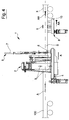
figures 1-5 show a side view of the cutting-off machine according to the invention, in accordance with a sequence of operating steps in succession. - Within the scope of the present invention the term "cutting-off" is intended as the complete separation of a length of continuous tube or one much longer than said length. Said cutting-off is the sum of a first cutting operation, performed on the tube to separate the tube length, and a subsequent cutting operation of the floating inner seam (i.e. free as previously separated from the tube by means of a special inner detaching tool) inside the tube.
- Furthermore, the invention is aimed at cutting tubes of any cross-section, obtained by means of welding a metal sheet along a longitudinal welding line, and operates preferably downstream of a removal unit of the outer welding seam.
-
Figure 1 shows a cutting-off machine according to the present invention, which is adapted to operate the cut of atube 100 which is made to advance along its own longitudinal axis "X" according to a direction of advance "A", for example by means of a roller bed or other guide means and support adapted to the purpose. Preferably, the rollers rotate around respective horizontal axes and have a double-cone shape ("hour-glass" shape), with reduced central diameter to realise a support and guide of thetube 100. - The cutting-off machine 1 comprises, in the first place, a cutting unit 1 adapted to receive a
tube 100 and to cut thetube 100 on a transversal or perpendicular plane to the longitudinal axis "X" of thetube 100, in particular on a vertical plane, in order to obtain a length "S" of tube separate from the remaining part of thetube 100. - Preferably, the cutting unit 2 is the orbital cutting type, i.e. having at least one or more cutting tools (not shown as known in themselves) mobile along a circular trajectory or curve which extends around the longitudinal axis "X" of the
tube 100.Figures 1-5 show, in an entirely exemplary and diagrammatic way, twoopposing tools 3 in the shape of circular blades, equipped with a rotary movement of revolution around the longitudinal axis "X" of thetube 100 and approach and radial distancing with respect to thetube 100. It is nonetheless possible to use other cutting tools, such as laser, water, plasma, etc., cutting heads. - Alternatively, it is possible to use other types of cutting unit 2, for example one or more linear advance blades.
- The cutting unit 2 cuts the
tube 100 along a cutting line resting on a vertical plane, preferably perpendicular, to the longitudinal axis "X" of thetube 100. Said plane is preferably vertical. - The cutting unit 2 is mobile along a parallel direction to the longitudinal axis "X" of the
tube 100 to operate with a technique of following thetube 100. In other words, the cutting unit 2 is mobile in a sliding way (for example on atrolley 4 or another structure adapted to the purpose) parallel to the longitudinal axis "X" of the tube advancing parallel to said advance direction "A" of thetube 100 and backwards according to an opposite direction "R". Thus, the cutting unit 2 may move at the same advance speed of thetube 100 for a time at least sufficient to complete cutting of thetube 100 and, subsequently, may be brought backwards to operate a new cut on a subsequent part of thetube 100. The above may be summarised by stating that the cutting unit 2 is mobile in a sliding way forwards and backwards between a first position, more upstream with respect to the advance direction "A" and visible, for example, infigure 1 , with which a starting position of cutting of thetube 100 corresponds, and a second position, more downstream with respect to the advance direction "A" and visible, for example, infigure 4 , with which a completed cutting position of thetube 100 corresponds. The operations necessary to complete cutting of thetube 100 will be described below in more detail. - Immediately downstream of the cutting unit 2 a cutting-off device 5 is arranged, configured to cut the
inner welding seam 200 floating inside thetube 100 and which is partially exposed after one length "S" of tube, separated from the remaining part of thetube 100, is distanced from said remaining part of thetube 100 by means of acceleration of the length "S". The cutting-off device 5 comprises ablade 6 mobile according to a respective transversal plane, preferably perpendicular, to the longitudinal axis "X" of thetube 100 under the action of anactuator 7. Preferably, theblade 6 acts on a respective vertical plane according to a guillotine movement. - The cutting-off device 5 is also mobile along a parallel direction to the longitudinal axis "X" of the
tube 100 to operate with a technique of following on thetube 100. In a like way to the cutting unit 2, the cutting-off device 5 is mobile in a sliding way parallel to the longitudinal axis "X" of thetube 100 advancing parallel to said advance direction "A" of thetube 100 and backwards according to an opposite direction "R". Thus, the cutting-off device 5 may move at the same advance speed as thetube 100 for a time at least sufficient to complete cutting of theinner seam 200 and, subsequently, may be brought backwards to operate a new cut on a subsequent part of theinner seam 200. The above may be summarised by stating that the cutting-off device 2 is mobile in a sliding way forwards and backwards between a first position, more upstream with respect to the advance direction "A" and visible, for example, infigure 1 , with which a starting position of cutting of thetube 100 corresponds, and a second position, more downstream with respect to the advance direction "A" and visible, for example, infigure 4 , with which a completed cutting position of thetube 100 corresponds. - According to a preferred embodiment of the invention, the cutting unit 2 and the cutting-off device 5 are solidly joined in the forward/backward movement "A", "R" along the longitudinal axis "X" of the
tube 100. For this purpose, the cutting unit 2 and the cutting-off device 5 may be arranged on thesame trolley 4 which moves forwards and backwards along the longitudinal axis "X" of thetube 100 between said first and second position. - The cutting-off machine 1 further comprises movement means 8 adapted to grip stably a length "S" of
tube 100 previously cut and to distance the length "S" from the cutting unit 2 along an advance direction "A" of thetube 100. In other words, the movement means 8 grip the length "S" of thetube 100 just cut by the cutting unit 2 and accelerate it along an advance direction "A", so as to distance the length "S" from the remaining part of thetube 100, thus exposing a section of the inner seam 200 (figure 3 ). - In the embodiment shown, the movement means 8 comprise a
grip 9, preferably a roller grip, mounted sliding on arespective trolley 10 mobile forwards and backwards along the longitudinal axis "X" of thetube 100. The movement means 8 could be realised in another way, provided they are adapted to the purpose of gripping the length "S" and distancing it from the remaining portion of thetube 100 to expose a section of theinner seam 200. - The movement means 8 are mobile in a sliding way forwards and backwards between a first position, more upstream with respect to the advance direction "A" and visible, for example, in
figure 1 , with which a starting position of cutting of thetube 100 corresponds, and a second position, more downstream with respect to the advance direction "A" and visible, for example, infigure 4 , with which a completed cutting position of thetube 100 corresponds. - The distance between the end positions assumed by the movement means 8 is greater than the distance between the end positions reached by the cutting unit 2 and by the cutting-off device 5. In other words, the movement means 8 have a travel, along the longitudinal axis "X" of the tube, which is greater with respect to the cutting unit 2 and the cutting-off device 5.
- Advantageously, the cutting-off device 5 is interposed between the cutting unit 2 and the movement means 8. Thus, the cutting-off device 5 is precisely at the section of the
inner seam 200 exposed following the distancing action exerted by the movement means 8 on the length "S" just cut. - The cutting-off machine 1 further comprises a control unit (not shown) configured to manage operation of the different parts of the cutting-off machine 1.
- In particular, the control unit is configured to activate initially the cutting unit 2 on reaching a predetermined position of the tube along the longitudinal axis "X". The cutting unit 2 is activated both by activating translation of the
trolley 4 and by activating, immediately or subsequently, the cutting tools 3 (figure 2 ). - Furthermore, the control unit is configured to perform the following operations in succession, after completion of cutting of the length "S" by the cutting unit 2:
- activating movement means 8 to obtain stable gripping of the length "S" of the
tube 100; - moving the movement means 8 by a pre-set travel away from the cutting unit 2 (achieving acceleration with respect to the speed of the cutting unit 2), and
- activating the cutting-off device 5 to cut the portion of the
inner seam 200 exposed following distancing of the length "S". - According to an alternative embodiment, activation of the movement means 8 to grip stably the length "S" after completion of cutting of the length "S" by the cutting unit 2 may be substituted by activation of movement means 8 to grip stably a front portion of the
tube 100 before cutting of the length "S" by the cutting unit 2. In this circumstance, the movement means 8 grip thetube 100 in its portion which will form the length "S" at the end of cutting and gripping remains stable until cutting of theinner seam 200. - In other words, rather than grip the length "S" of tube after cutting, it is possible, by means of the movement means 8 (clamps), to grip the front part of the
tube 100 before cutting and, on completing cutting, maintain the length "S" of thetube 100 gripped and advance it to distance it from the remaining part of thetube 100. - Advantageously, the control unit sets an advance of the movement means 8 for a sufficient travel to allow a rear edge of the length "S" to overtake the cutting-off device 5 (and, in particular, to overtake the plane on which the
blade 6 acts, which will therefore be positioned above the section of theinner seam 200 exposed). Subsequently to the moment when the rear edge of the length "S" overtakes the cutting-off device 5, the control unit maintains the movement means 8 at the same speed as thetube 100 or may continue to distance the length "S". - Subsequently to cutting of the
inner seam 200, the movement means 8 (or alternatively further means not shown) conduct the length "S" (having inside it a length of the inner seam 200) towards a receiving station which sorts the length "S" or alternatively submits the length "S" to further processing. - Functioning of the cutting-off machine 1 with reference to
figures 1-5 is now described. -
Figure 1 shows the machine 1 immediately before cutting starts, wherein thetube 100 is inserted through the cutting unit 2, still inactive but already advancing in the same direction as advance direction "A" of thetube 100 together with the cutting-off device 5, which is inactive. The movement means 8 also advance at the same speed as thetube 100, but they are also inactive (the grips or pincers do not grip the tube 100). In this step, the cutting unit 2, the cutting-off device 5 and the movement means 8 move following thetube 100 at the same speed as thetube 100. -
Figure 2 shows activation of thecutting tools 3 of the cutting unit, which realises cutting of thetube 100 and therefore separation of the length "S". -
Figure 3 shows the subsequent step wherein, also with the system of following the tube, the movement means 8 tighten the grips or the pincers on the length "S" and are accelerated (direction of movement indicated with "AA" to identify a greater speed with respect to the cutting unit 2 and the cutting-off device 5) to distance the length "S" from the remaining part of thetube 100. -
Figure 4 shows activation of the cutting-off device 5, which cuts the exposed section of theinner seam 200 between length "S" and the remaining part of thetube 100, by means of guillotine descent of theblade 6. -
Figure 5 shows the subsequent return step (direction "R") by the cutting unit 2, the cutting-off device 5 and the movement means 8 (whose pincers or grips have released the grip on the length "S", which continues to advance on the roller bed), which return to the initial position offigure 1 to start a new work cycle. - The present invention achieves the proposed objects, overcoming the disadvantages complained in the known art.
- Configuration of the machine according to the invention allows, in fact, complete cutting of the tube (cutting of the length and subsequent cutting of the inner seam) in absolute safety and precision, since the movement means determine, at every moment and in a controlled way (for example by means of an advance curve imposed by the control unit) the position assumed by the length just cut. It is therefore possible to activate the cutting-off device on reaching an optimal configuration, particularly at the moment when the length has reached a safe distance from the tube and from the cutting-off device.
- Consequently, the massive use of photocells of the prior art, with the related problems of reliability, may be avoided, obtaining a structure of the cutting-off machine which is simple and reliable.
Claims (10)
- A cutting-off machine, comprising:- a cutting unit (2) being enabled to receive a tube (100) and to cut the tube (100) according to a plane transversal to a longitudinal axis (X) of the tube (100); characterised in that said machine further comprises:- movement means (8) enabled to grip stably a length (S) of cut tube (100) and move said length (S) away from the cutting unit (2) along a direction of advance (A) of the tube (100);- a cutting-off device (5) interposed between said cutting unit (2) and said movement means (8) and configured to realise cutting off of an inner welding seam (200) floating inside said tube (100).
- The machine according to claim 1, wherein said cutting-off device (5) and said cutting unit (2) act along respective planes transversal to the longitudinal axis (X) of the tube (100).
- The machine according to claim 1 or 2, further comprising a control unit configured to realise the following operations in succession:- activate said movement means (8) to realise a stable grip of a length (S) of tube (100) cut from a continuous tube (100) by means of said cutting unit (2);- move said movement means (8) by a pre-set travel away from the cutting unit (2) to distance the length (S) from the remaining part of the tube (100), and- activate said cutting-off device (5) to realise cutting-off of an inner seam (200) present inside said length (S) and said remaining part of the tube (100) at a zone between said length (S) and said remaining part of the tube (100).
- The machine according to any one of the previous claims, wherein said cutting-off device (5) comprises a blade (6) vertically movable according to a guillotine movement.
- The machine according to any one of the previous claims, wherein said movement means (8) comprise a gripper or a vice, sliding mounted on a carriage (4) moveable forwards and backwards along the longitudinal axis (X) of the tube (100).
- The machine according to any one of the previous claims, wherein said cutting-off device (5) is movable along a direction parallel to the longitudinal axis (X) of the tube (100) to operate with a tracking technique on the tube (100).
- The machine according to claim 6, wherein said cutting unit (2) is movable along a direction parallel to the longitudinal axis (X) of the tube (100) to operate with a tracking technique on the tube (100), and wherein the cutting unit (2) and the cutting-off device (5) are solidly constrained to each other in the movement along said parallel direction to the longitudinal axis (X) of the tube (100).
- The machine according to any one of the previous claims, wherein said cutting unit (2) is the orbital type, presenting at least one cutting tool (3) movable along a trajectory which develops around the longitudinal axis (X) of the tube (100).
- A method for cutting off a tube (100), comprising the following steps in the specific order indicated:- prepare a tube (100) welded along the longitudinal welding line and presenting internally a welding seam (200) detached from said tube (100);- separate a length (S) of tube from said tube (100) by means of cutting according to a transversal plane to the longitudinal axis (X) of the tube (100);- advance said length (S) away from the remaining part of the tube (100) along a direction (A) parallel to the longitudinal axis (X) of the tube (100) so as to expose a section of said inner seam (200);- realise a cutting-off of said inner seam (200) by means of a guillotine cutting-off device (5).
- The method according to claim 9, wherein said step of advancing the length (S) away from the remaining part of the tube (100) is realised by advancing said length (S) by a sufficient travel to allow a back edge of the length (S) to go beyond said cutting-off device (5).
Applications Claiming Priority (1)
| Application Number | Priority Date | Filing Date | Title |
|---|---|---|---|
| IT000332A ITMO20130332A1 (en) | 2013-12-06 | 2013-12-06 | CUTTING MACHINE |
Publications (2)
| Publication Number | Publication Date |
|---|---|
| EP2881214A1 EP2881214A1 (en) | 2015-06-10 |
| EP2881214B1 true EP2881214B1 (en) | 2016-02-03 |
Family
ID=49887095
Family Applications (1)
| Application Number | Title | Priority Date | Filing Date |
|---|---|---|---|
| EP14193503.1A Active EP2881214B1 (en) | 2013-12-06 | 2014-11-17 | Tube cutting-off machine |
Country Status (8)
| Country | Link |
|---|---|
| US (1) | US9434012B2 (en) |
| EP (1) | EP2881214B1 (en) |
| JP (1) | JP6208649B2 (en) |
| BR (1) | BR102014030225A2 (en) |
| CA (1) | CA2873010C (en) |
| ES (1) | ES2566920T3 (en) |
| IT (1) | ITMO20130332A1 (en) |
| MX (1) | MX354338B (en) |
Families Citing this family (12)
| Publication number | Priority date | Publication date | Assignee | Title |
|---|---|---|---|---|
| US9694424B2 (en) * | 2014-06-20 | 2017-07-04 | Navarro IP, LLC | Apparatus for cutting material and method |
| CN109895367B (en) * | 2017-12-07 | 2021-04-30 | 蓝思智能机器人(长沙)有限公司 | Cutting mechanism |
| CN107877006B (en) * | 2017-12-27 | 2023-07-07 | 济南金强激光数控设备有限公司 | Full-automatic numerical control laser pipe cutting machine |
| CN108247220B (en) * | 2018-01-31 | 2019-09-03 | 中国电子科技集团公司第三十八研究所 | A kind of laser dismantling method of microwave component |
| CN108941745A (en) * | 2018-07-06 | 2018-12-07 | 安徽机电职业技术学院 | A kind of energy-efficient steel pipe cutting device |
| IT201800020845A1 (en) | 2018-12-21 | 2020-06-21 | Fives Oto Spa | Weld seam shearing device |
| CN109894679B (en) * | 2019-03-08 | 2023-12-19 | 广东科技学院 | Workpiece processing equipment |
| CN111037626B (en) * | 2019-09-30 | 2021-04-23 | 浩联保温管业有限公司 | Pipe online cutting system |
| CN115625374B (en) * | 2022-10-09 | 2024-09-20 | 沈阳康特机电设备有限公司 | Method for cutting off weld joint of online steel pipe |
| CN118385834B (en) * | 2024-05-31 | 2024-11-01 | 浙江鸿翔筑能科技股份有限公司 | Tubular steel member welding machine based on constructional engineering and welding method thereof |
| CN119035659B (en) * | 2024-11-01 | 2025-01-24 | 江苏中燕叉车制造有限公司 | A fork scraping device with cleaning function |
| CN119839353B (en) * | 2025-01-14 | 2025-09-26 | 苏州索雷特自动化科技有限公司 | Method and device for processing welding interconnection strips |
Family Cites Families (29)
| Publication number | Priority date | Publication date | Assignee | Title |
|---|---|---|---|---|
| GB1128691A (en) * | 1965-04-01 | 1968-10-02 | Bristol Aeroplane Plastics Ltd | Methods of and machines for cutting slots in tubes |
| US3630126A (en) * | 1969-08-18 | 1971-12-28 | Ernest Winston Ronai | Apparatus for cutting tubes |
| US3924502A (en) * | 1975-01-30 | 1975-12-09 | Alpha Ind Inc | Clamping die jaw insert for tube cutoff apparatus |
| US4084463A (en) * | 1977-01-14 | 1978-04-18 | Sekisui Kagaku Kogyo Kabushiki Kaisha | Apparatus for cutting and chamfering irregular shaped pipes |
| US4337680A (en) * | 1980-12-05 | 1982-07-06 | Borzym John J | Die jaw members for tube cutoff apparatus |
| US4457200A (en) * | 1982-09-23 | 1984-07-03 | Alpha Industries Inc. | Method for cutting heavy wall tube |
| JPS5981015A (en) * | 1982-10-29 | 1984-05-10 | Kawasaki Heavy Ind Ltd | Square pipe cutter accompanied by edge preparation |
| JPS62117017U (en) * | 1986-01-20 | 1987-07-25 | ||
| US4919025A (en) * | 1988-10-24 | 1990-04-24 | General Motors Corporation | Method and apparatus for processing continuously manufactured tubing |
| JPH0688172B2 (en) * | 1989-02-23 | 1994-11-09 | 日新製鋼株式会社 | Circular pipe traveling cutting device |
| JP2735954B2 (en) * | 1991-02-14 | 1998-04-02 | 三菱重工業株式会社 | Milling type traveling steel pipe cutting machine |
| JP3159462B2 (en) * | 1991-04-30 | 2001-04-23 | 日下部電機株式会社 | Press type traveling pipe cutting machine |
| DE4117574C1 (en) * | 1991-05-29 | 1992-07-09 | F.H. Jung Maschinenfabrik Gmbh, 6251 Beselich, De | |
| US6260395B1 (en) * | 1996-03-05 | 2001-07-17 | Adaptive Motion Control Systems, Inc. | Vertically oriented apparatus for bending tubing, and method of using same |
| ATE208248T1 (en) * | 1996-08-30 | 2001-11-15 | Sica Spa | METHOD FOR CUTTING A TUBULAR ROD |
| US6439089B1 (en) * | 1996-12-23 | 2002-08-27 | Shear, Llc | Apparatus for shearing multi-walled workpieces |
| JPH10235514A (en) * | 1997-02-25 | 1998-09-08 | Nippon Steel Corp | Travel cutting device with internal bead cutting device |
| US5964137A (en) * | 1998-07-23 | 1999-10-12 | Jung; William Emil | Bantam twin pipe notcher |
| JP2002370121A (en) * | 2001-06-15 | 2002-12-24 | Mitsubishi Heavy Ind Ltd | Milling cut-off device with internal bead cutter |
| US7000512B2 (en) * | 2002-11-26 | 2006-02-21 | Plastipak Packaging, Inc. | Blow molding trimming |
| DE102007007061A1 (en) * | 2007-02-08 | 2008-08-14 | Schumag Ag | Separating device for substantially linear workpieces and method for separating substantially linear workpieces |
| ITRN20070034A1 (en) * | 2007-06-27 | 2008-12-28 | Sica Spa | MACHINE AND CUTTING METHOD OF A CONTINUOUS EXTRUDED TUBE IN MINOR SPOTS AND PREDETERMINED LENGTH. |
| US20110173786A1 (en) * | 2010-01-21 | 2011-07-21 | Dionex Corporation | Cutting analytical instrument tubing |
| DE102010027199A1 (en) * | 2010-07-08 | 2012-01-12 | Elumatec Gmbh | Turntable unit for a profile machining center |
| IT1402081B1 (en) * | 2010-09-22 | 2013-08-28 | Sovema Spa | GRID FORMING MACHINE FOR THE CONSTRUCTION OF ELECTRIC STORAGE PLATES. |
| US9566652B2 (en) * | 2011-04-29 | 2017-02-14 | Gustav M. Nasiell | Cordless clamping handle tubing cutter tool |
| ITMO20120082A1 (en) * | 2012-03-28 | 2013-09-29 | Oto S P A | METHOD FOR CUTTING MANUFACTURED FLIGHTS. |
| CA2829002C (en) * | 2013-09-27 | 2020-06-09 | Omachron Intellectual Property Inc. | Pipe cutting tool and methods for use |
| US9694424B2 (en) * | 2014-06-20 | 2017-07-04 | Navarro IP, LLC | Apparatus for cutting material and method |
-
2013
- 2013-12-06 IT IT000332A patent/ITMO20130332A1/en unknown
-
2014
- 2014-11-17 ES ES14193503.1T patent/ES2566920T3/en active Active
- 2014-11-17 EP EP14193503.1A patent/EP2881214B1/en active Active
- 2014-12-01 CA CA2873010A patent/CA2873010C/en not_active Expired - Fee Related
- 2014-12-02 US US14/558,343 patent/US9434012B2/en not_active Expired - Fee Related
- 2014-12-03 MX MX2014014812A patent/MX354338B/en active IP Right Grant
- 2014-12-03 BR BR102014030225A patent/BR102014030225A2/en not_active Application Discontinuation
- 2014-12-04 JP JP2014246156A patent/JP6208649B2/en not_active Expired - Fee Related
Also Published As
| Publication number | Publication date |
|---|---|
| EP2881214A1 (en) | 2015-06-10 |
| JP6208649B2 (en) | 2017-10-04 |
| CA2873010C (en) | 2018-02-20 |
| CA2873010A1 (en) | 2015-06-06 |
| MX354338B (en) | 2018-02-27 |
| US20150158099A1 (en) | 2015-06-11 |
| BR102014030225A2 (en) | 2015-09-15 |
| MX2014014812A (en) | 2015-07-01 |
| ES2566920T3 (en) | 2016-04-18 |
| ITMO20130332A1 (en) | 2015-06-07 |
| US9434012B2 (en) | 2016-09-06 |
| JP2015112713A (en) | 2015-06-22 |
Similar Documents
| Publication | Publication Date | Title |
|---|---|---|
| CA2873010C (en) | A cutting-off machine | |
| US8445811B2 (en) | Device for the weld joining of sheet metal strips | |
| US9067255B2 (en) | Bending apparatus for rod-shaped workpieces | |
| US20080202299A1 (en) | Cutting device for substantially linear workpieces and method for cutting substantially linear workpieces | |
| CN207289589U (en) | A kind of automatic beginning material, the multi-functional sawing sheet equipment for removing tailing | |
| EP2845840A1 (en) | Machine and method for performing cutting operations on laminated-glass plates | |
| JP2005186126A (en) | Pipe processing method and pipe processing system | |
| US6295906B1 (en) | Apparatus and method for advancing, cutting and ejecting a tubular workpiece | |
| CN105081458A (en) | Sawing machine for sawing metal workpieces | |
| US3715941A (en) | Slitting machine | |
| US20160107215A1 (en) | Assembly for and method of marking and cutting wires, and machine comprising said assembly | |
| CN204159973U (en) | The cutting machine of automatic location section bar | |
| CN106984868A (en) | A kind of processing unit (plant) and application method for automobile cooling pipe notch | |
| EP3549689B1 (en) | Strip profiling line comprising a cutting device | |
| EP3670049A1 (en) | Weld bead cutting device | |
| CN220679135U (en) | U-shaped pipe processing equipment | |
| KR20120041665A (en) | Apparatus for producing blanks from a wire material | |
| CN101920359B (en) | Cutting machine for metal tube | |
| KR20210127753A (en) | Apparatus for orbital cutting and straightening of tubes | |
| JP6034482B2 (en) | How to cut a moving product | |
| CN214866885U (en) | Straightening and cutting machine for wire rods | |
| KR20180080488A (en) | Hanger cutter for manufacturing planges | |
| RU2479391C1 (en) | Device for arc welding of strips at continuous metallurgical plants | |
| US5701648A (en) | Multi-functional fabricating system for welding electrodes | |
| KR101308245B1 (en) | Apparatus for producing blanks from a wire material |
Legal Events
| Date | Code | Title | Description |
|---|---|---|---|
| PUAI | Public reference made under article 153(3) epc to a published international application that has entered the european phase |
Free format text: ORIGINAL CODE: 0009012 |
|
| 17P | Request for examination filed |
Effective date: 20141117 |
|
| AK | Designated contracting states |
Kind code of ref document: A1 Designated state(s): AL AT BE BG CH CY CZ DE DK EE ES FI FR GB GR HR HU IE IS IT LI LT LU LV MC MK MT NL NO PL PT RO RS SE SI SK SM TR |
|
| AX | Request for extension of the european patent |
Extension state: BA ME |
|
| R17P | Request for examination filed (corrected) |
Effective date: 20150612 |
|
| RBV | Designated contracting states (corrected) |
Designated state(s): AL AT BE BG CH CY CZ DE DK EE ES FI FR GB GR HR HU IE IS IT LI LT LU LV MC MK MT NL NO PL PT RO RS SE SI SK SM TR |
|
| GRAP | Despatch of communication of intention to grant a patent |
Free format text: ORIGINAL CODE: EPIDOSNIGR1 |
|
| INTG | Intention to grant announced |
Effective date: 20150731 |
|
| GRAS | Grant fee paid |
Free format text: ORIGINAL CODE: EPIDOSNIGR3 |
|
| GRAA | (expected) grant |
Free format text: ORIGINAL CODE: 0009210 |
|
| AK | Designated contracting states |
Kind code of ref document: B1 Designated state(s): AL AT BE BG CH CY CZ DE DK EE ES FI FR GB GR HR HU IE IS IT LI LT LU LV MC MK MT NL NO PL PT RO RS SE SI SK SM TR |
|
| REG | Reference to a national code |
Ref country code: GB Ref legal event code: FG4D |
|
| REG | Reference to a national code |
Ref country code: AT Ref legal event code: REF Ref document number: 773418 Country of ref document: AT Kind code of ref document: T Effective date: 20160215 Ref country code: CH Ref legal event code: EP |
|
| REG | Reference to a national code |
Ref country code: IE Ref legal event code: FG4D |
|
| REG | Reference to a national code |
Ref country code: DE Ref legal event code: R096 Ref document number: 602014000851 Country of ref document: DE |
|
| REG | Reference to a national code |
Ref country code: ES Ref legal event code: FG2A Ref document number: 2566920 Country of ref document: ES Kind code of ref document: T3 Effective date: 20160418 |
|
| REG | Reference to a national code |
Ref country code: LT Ref legal event code: MG4D Ref country code: NL Ref legal event code: MP Effective date: 20160203 |
|
| REG | Reference to a national code |
Ref country code: AT Ref legal event code: MK05 Ref document number: 773418 Country of ref document: AT Kind code of ref document: T Effective date: 20160203 |
|
| PG25 | Lapsed in a contracting state [announced via postgrant information from national office to epo] |
Ref country code: NO Free format text: LAPSE BECAUSE OF FAILURE TO SUBMIT A TRANSLATION OF THE DESCRIPTION OR TO PAY THE FEE WITHIN THE PRESCRIBED TIME-LIMIT Effective date: 20160503 Ref country code: HR Free format text: LAPSE BECAUSE OF FAILURE TO SUBMIT A TRANSLATION OF THE DESCRIPTION OR TO PAY THE FEE WITHIN THE PRESCRIBED TIME-LIMIT Effective date: 20160203 Ref country code: FI Free format text: LAPSE BECAUSE OF FAILURE TO SUBMIT A TRANSLATION OF THE DESCRIPTION OR TO PAY THE FEE WITHIN THE PRESCRIBED TIME-LIMIT Effective date: 20160203 Ref country code: GR Free format text: LAPSE BECAUSE OF FAILURE TO SUBMIT A TRANSLATION OF THE DESCRIPTION OR TO PAY THE FEE WITHIN THE PRESCRIBED TIME-LIMIT Effective date: 20160504 |
|
| PG25 | Lapsed in a contracting state [announced via postgrant information from national office to epo] |
Ref country code: RS Free format text: LAPSE BECAUSE OF FAILURE TO SUBMIT A TRANSLATION OF THE DESCRIPTION OR TO PAY THE FEE WITHIN THE PRESCRIBED TIME-LIMIT Effective date: 20160203 Ref country code: IS Free format text: LAPSE BECAUSE OF FAILURE TO SUBMIT A TRANSLATION OF THE DESCRIPTION OR TO PAY THE FEE WITHIN THE PRESCRIBED TIME-LIMIT Effective date: 20160603 Ref country code: AT Free format text: LAPSE BECAUSE OF FAILURE TO SUBMIT A TRANSLATION OF THE DESCRIPTION OR TO PAY THE FEE WITHIN THE PRESCRIBED TIME-LIMIT Effective date: 20160203 Ref country code: PT Free format text: LAPSE BECAUSE OF FAILURE TO SUBMIT A TRANSLATION OF THE DESCRIPTION OR TO PAY THE FEE WITHIN THE PRESCRIBED TIME-LIMIT Effective date: 20160603 Ref country code: LV Free format text: LAPSE BECAUSE OF FAILURE TO SUBMIT A TRANSLATION OF THE DESCRIPTION OR TO PAY THE FEE WITHIN THE PRESCRIBED TIME-LIMIT Effective date: 20160203 Ref country code: NL Free format text: LAPSE BECAUSE OF FAILURE TO SUBMIT A TRANSLATION OF THE DESCRIPTION OR TO PAY THE FEE WITHIN THE PRESCRIBED TIME-LIMIT Effective date: 20160203 Ref country code: LT Free format text: LAPSE BECAUSE OF FAILURE TO SUBMIT A TRANSLATION OF THE DESCRIPTION OR TO PAY THE FEE WITHIN THE PRESCRIBED TIME-LIMIT Effective date: 20160203 Ref country code: PL Free format text: LAPSE BECAUSE OF FAILURE TO SUBMIT A TRANSLATION OF THE DESCRIPTION OR TO PAY THE FEE WITHIN THE PRESCRIBED TIME-LIMIT Effective date: 20160203 Ref country code: SE Free format text: LAPSE BECAUSE OF FAILURE TO SUBMIT A TRANSLATION OF THE DESCRIPTION OR TO PAY THE FEE WITHIN THE PRESCRIBED TIME-LIMIT Effective date: 20160203 |
|
| PG25 | Lapsed in a contracting state [announced via postgrant information from national office to epo] |
Ref country code: DK Free format text: LAPSE BECAUSE OF FAILURE TO SUBMIT A TRANSLATION OF THE DESCRIPTION OR TO PAY THE FEE WITHIN THE PRESCRIBED TIME-LIMIT Effective date: 20160203 Ref country code: EE Free format text: LAPSE BECAUSE OF FAILURE TO SUBMIT A TRANSLATION OF THE DESCRIPTION OR TO PAY THE FEE WITHIN THE PRESCRIBED TIME-LIMIT Effective date: 20160203 |
|
| REG | Reference to a national code |
Ref country code: DE Ref legal event code: R097 Ref document number: 602014000851 Country of ref document: DE |
|
| REG | Reference to a national code |
Ref country code: FR Ref legal event code: PLFP Year of fee payment: 3 |
|
| PG25 | Lapsed in a contracting state [announced via postgrant information from national office to epo] |
Ref country code: SK Free format text: LAPSE BECAUSE OF FAILURE TO SUBMIT A TRANSLATION OF THE DESCRIPTION OR TO PAY THE FEE WITHIN THE PRESCRIBED TIME-LIMIT Effective date: 20160203 Ref country code: RO Free format text: LAPSE BECAUSE OF FAILURE TO SUBMIT A TRANSLATION OF THE DESCRIPTION OR TO PAY THE FEE WITHIN THE PRESCRIBED TIME-LIMIT Effective date: 20160203 Ref country code: CZ Free format text: LAPSE BECAUSE OF FAILURE TO SUBMIT A TRANSLATION OF THE DESCRIPTION OR TO PAY THE FEE WITHIN THE PRESCRIBED TIME-LIMIT Effective date: 20160203 Ref country code: SM Free format text: LAPSE BECAUSE OF FAILURE TO SUBMIT A TRANSLATION OF THE DESCRIPTION OR TO PAY THE FEE WITHIN THE PRESCRIBED TIME-LIMIT Effective date: 20160203 |
|
| PLBE | No opposition filed within time limit |
Free format text: ORIGINAL CODE: 0009261 |
|
| STAA | Information on the status of an ep patent application or granted ep patent |
Free format text: STATUS: NO OPPOSITION FILED WITHIN TIME LIMIT |
|
| PG25 | Lapsed in a contracting state [announced via postgrant information from national office to epo] |
Ref country code: BE Free format text: LAPSE BECAUSE OF FAILURE TO SUBMIT A TRANSLATION OF THE DESCRIPTION OR TO PAY THE FEE WITHIN THE PRESCRIBED TIME-LIMIT Effective date: 20160203 |
|
| 26N | No opposition filed |
Effective date: 20161104 |
|
| PG25 | Lapsed in a contracting state [announced via postgrant information from national office to epo] |
Ref country code: SI Free format text: LAPSE BECAUSE OF FAILURE TO SUBMIT A TRANSLATION OF THE DESCRIPTION OR TO PAY THE FEE WITHIN THE PRESCRIBED TIME-LIMIT Effective date: 20160203 Ref country code: BG Free format text: LAPSE BECAUSE OF FAILURE TO SUBMIT A TRANSLATION OF THE DESCRIPTION OR TO PAY THE FEE WITHIN THE PRESCRIBED TIME-LIMIT Effective date: 20160503 |
|
| REG | Reference to a national code |
Ref country code: IE Ref legal event code: MM4A |
|
| PG25 | Lapsed in a contracting state [announced via postgrant information from national office to epo] |
Ref country code: LU Free format text: LAPSE BECAUSE OF NON-PAYMENT OF DUE FEES Effective date: 20161130 |
|
| REG | Reference to a national code |
Ref country code: FR Ref legal event code: PLFP Year of fee payment: 4 |
|
| PG25 | Lapsed in a contracting state [announced via postgrant information from national office to epo] |
Ref country code: IE Free format text: LAPSE BECAUSE OF NON-PAYMENT OF DUE FEES Effective date: 20161117 |
|
| PG25 | Lapsed in a contracting state [announced via postgrant information from national office to epo] |
Ref country code: HU Free format text: LAPSE BECAUSE OF FAILURE TO SUBMIT A TRANSLATION OF THE DESCRIPTION OR TO PAY THE FEE WITHIN THE PRESCRIBED TIME-LIMIT; INVALID AB INITIO Effective date: 20141117 |
|
| PG25 | Lapsed in a contracting state [announced via postgrant information from national office to epo] |
Ref country code: MK Free format text: LAPSE BECAUSE OF FAILURE TO SUBMIT A TRANSLATION OF THE DESCRIPTION OR TO PAY THE FEE WITHIN THE PRESCRIBED TIME-LIMIT Effective date: 20160203 Ref country code: CY Free format text: LAPSE BECAUSE OF FAILURE TO SUBMIT A TRANSLATION OF THE DESCRIPTION OR TO PAY THE FEE WITHIN THE PRESCRIBED TIME-LIMIT Effective date: 20160203 Ref country code: MC Free format text: LAPSE BECAUSE OF FAILURE TO SUBMIT A TRANSLATION OF THE DESCRIPTION OR TO PAY THE FEE WITHIN THE PRESCRIBED TIME-LIMIT Effective date: 20160203 |
|
| PG25 | Lapsed in a contracting state [announced via postgrant information from national office to epo] |
Ref country code: CH Free format text: LAPSE BECAUSE OF NON-PAYMENT OF DUE FEES Effective date: 20171130 Ref country code: LI Free format text: LAPSE BECAUSE OF NON-PAYMENT OF DUE FEES Effective date: 20171130 |
|
| PG25 | Lapsed in a contracting state [announced via postgrant information from national office to epo] |
Ref country code: MT Free format text: LAPSE BECAUSE OF NON-PAYMENT OF DUE FEES Effective date: 20161117 |
|
| PG25 | Lapsed in a contracting state [announced via postgrant information from national office to epo] |
Ref country code: AL Free format text: LAPSE BECAUSE OF FAILURE TO SUBMIT A TRANSLATION OF THE DESCRIPTION OR TO PAY THE FEE WITHIN THE PRESCRIBED TIME-LIMIT Effective date: 20160203 |
|
| GBPC | Gb: european patent ceased through non-payment of renewal fee |
Effective date: 20181117 |
|
| PG25 | Lapsed in a contracting state [announced via postgrant information from national office to epo] |
Ref country code: GB Free format text: LAPSE BECAUSE OF NON-PAYMENT OF DUE FEES Effective date: 20181117 |
|
| PGFP | Annual fee paid to national office [announced via postgrant information from national office to epo] |
Ref country code: ES Payment date: 20191219 Year of fee payment: 6 Ref country code: FR Payment date: 20191126 Year of fee payment: 6 |
|
| PGFP | Annual fee paid to national office [announced via postgrant information from national office to epo] |
Ref country code: DE Payment date: 20191230 Year of fee payment: 6 |
|
| REG | Reference to a national code |
Ref country code: DE Ref legal event code: R119 Ref document number: 602014000851 Country of ref document: DE |
|
| PG25 | Lapsed in a contracting state [announced via postgrant information from national office to epo] |
Ref country code: FR Free format text: LAPSE BECAUSE OF NON-PAYMENT OF DUE FEES Effective date: 20201130 |
|
| PG25 | Lapsed in a contracting state [announced via postgrant information from national office to epo] |
Ref country code: DE Free format text: LAPSE BECAUSE OF NON-PAYMENT OF DUE FEES Effective date: 20210601 |
|
| REG | Reference to a national code |
Ref country code: ES Ref legal event code: FD2A Effective date: 20220201 |
|
| PG25 | Lapsed in a contracting state [announced via postgrant information from national office to epo] |
Ref country code: ES Free format text: LAPSE BECAUSE OF NON-PAYMENT OF DUE FEES Effective date: 20201118 |
|
| PG25 | Lapsed in a contracting state [announced via postgrant information from national office to epo] |
Ref country code: TR Free format text: LAPSE BECAUSE OF NON-PAYMENT OF DUE FEES Effective date: 20191117 |
|
| PGFP | Annual fee paid to national office [announced via postgrant information from national office to epo] |
Ref country code: IT Payment date: 20251127 Year of fee payment: 12 |