EP2881181A1 - Method for determining electrical parameters of a tuning unit for an ultrasonic transducer - Google Patents
Method for determining electrical parameters of a tuning unit for an ultrasonic transducer Download PDFInfo
- Publication number
- EP2881181A1 EP2881181A1 EP13196307.6A EP13196307A EP2881181A1 EP 2881181 A1 EP2881181 A1 EP 2881181A1 EP 13196307 A EP13196307 A EP 13196307A EP 2881181 A1 EP2881181 A1 EP 2881181A1
- Authority
- EP
- European Patent Office
- Prior art keywords
- frequency
- tuning unit
- parallel
- resistance
- circuit
- Prior art date
- Legal status (The legal status is an assumption and is not a legal conclusion. Google has not performed a legal analysis and makes no representation as to the accuracy of the status listed.)
- Withdrawn
Links
Images

Classifications
-
- B—PERFORMING OPERATIONS; TRANSPORTING
- B06—GENERATING OR TRANSMITTING MECHANICAL VIBRATIONS IN GENERAL
- B06B—METHODS OR APPARATUS FOR GENERATING OR TRANSMITTING MECHANICAL VIBRATIONS OF INFRASONIC, SONIC, OR ULTRASONIC FREQUENCY, e.g. FOR PERFORMING MECHANICAL WORK IN GENERAL
- B06B1/00—Methods or apparatus for generating mechanical vibrations of infrasonic, sonic, or ultrasonic frequency
- B06B1/02—Methods or apparatus for generating mechanical vibrations of infrasonic, sonic, or ultrasonic frequency making use of electrical energy
- B06B1/0207—Driving circuits
- B06B1/0215—Driving circuits for generating pulses, e.g. bursts of oscillations, envelopes
-
- B—PERFORMING OPERATIONS; TRANSPORTING
- B06—GENERATING OR TRANSMITTING MECHANICAL VIBRATIONS IN GENERAL
- B06B—METHODS OR APPARATUS FOR GENERATING OR TRANSMITTING MECHANICAL VIBRATIONS OF INFRASONIC, SONIC, OR ULTRASONIC FREQUENCY, e.g. FOR PERFORMING MECHANICAL WORK IN GENERAL
- B06B2201/00—Indexing scheme associated with B06B1/0207 for details covered by B06B1/0207 but not provided for in any of its subgroups
- B06B2201/30—Indexing scheme associated with B06B1/0207 for details covered by B06B1/0207 but not provided for in any of its subgroups with electronic damping
Definitions
- the invention relates to a method for determining electrical parameters of a tuning unit for an ultrasonic transducer.
- This ultrasonic transducer has a voltage transformer and is represented by an equivalent electrical circuit diagram with a series circuit consisting of an inductor, a capacitor and a resistor having a series resonant frequency, wherein the tuning unit has a parallel circuit with a capacitance and a resistor, which together with a parallel-connected inductance of the voltage transformer forms a parallel resonant frequency having a parallel resonant circuit.
- Ultrasonic devices find use, for example, as parking aids or distance measurement for other purposes or for room monitoring.
- Ultrasonic devices typically include an ultrasonic transducer that converts an electrical signal into an acoustic or vice versa.
- An ultrasonic transducer can therefore be used both as transmitter and receiver.
- ultrasonic transducers which are switched intermittently as a transmitter and receiver.
- an ultrasound transducer has a resonant circuit in the form of a series resonant circuit which, in the equivalent circuit diagram of the ultrasound transducer, comprises an inductance, a capacitance and a resistor and defines a component-related series resonant frequency.
- the overall systems of ultrasonic transducers sometimes include tuning units that include a tuning capacitance and a tuning resistor in parallel.
- the tuning unit is connected between a voltage converter and the ultrasonic transducer itself. This is parallel to the tuning unit defined by the voltage transformer Inductance, so that the tuning unit forms a parallel resonance circuit together with this inductance.
- an ultrasound transducer value is set to a power adaptation, i. Value on the tuning of the resonant frequencies of both resonant circuits, which should be as equal as possible.
- the parallel resonant circuit is suitably damped by means of a resistor in order to favorably influence the decay process, that is, to be prepared as soon as possible after the end of the transmission operation for the reception of ultrasonic signals. Namely, if the ultrasonic transducer still oscillates while it is already exposed to incoming ultrasonic signals, these incoming ultrasonic signals can not be detected with sufficient reliability.
- the object of the invention is therefore to be able to determine the electrical parameters of a tuning unit for an ultrasonic transducer with respect to the above criteria.
- the inventive approach is to minimize the decay of the overall system of tuning unit and ultrasonic transducer (including voltage transformer), so that the settling time is reduced.
- a (damping) resistor is integrated in the tuning unit, which is connected in parallel to a tuning capacity of the tuning unit, which compensates for example, in practice sometimes quite large temperature coefficient of the piezoelectric crystal of the ultrasonic transducer at least partially.
- the frequency response should on the one hand be sufficiently narrow band in order to avoid interference of the received signal to a sufficient extent, but on the other hand not be too narrow band, as this adversely affects the frequency tolerance, which in particular when using the ultrasonic transducer for distance measurement in the application as eg motor vehicle Parking assistance may be a disadvantage.
- the inductance of the parallel resonant circuit of the tuning unit is selected at a predetermined value for the capacity such that the parallel resonance frequency of the parallel resonant circuit of the tuning unit is equal to the series resonant frequency of the series circuit of the ultrasonic transducer.
- the invention is particularly useful if the determination of the resistance is made in the event that the ultrasonic transducer is operated alternately in a transmitting module for emitting ultrasonic signals in the form of ultrasonic pulses and in particular ultrasonic pulse packets and in a receiving mode for receiving ultrasonic signals ,
- Another method for determining the optimum value or resistance of the parallel resonant circuit is to determine the frequency response of the total system of tuning unit and ultrasonic transducer in the case of operation of the entire system in a receiving mode for a predetermined initial value of the resistance of the parallel resonant circuit and the value This resistance gradually or continuously or quasi continuously until a target value is reached, in which the frequency response has a maximum at which the second derivative after the frequency is equal to or substantially equal to zero.
- the resistance value of the series circuit of the equivalent circuit of the ultrasonic transducer is selected as the initial value for the resistance of the parallel resonant circuit. If, for whatever reason, an error occurs in this procedure, for example because the two resonant circuits are out of tune, then the method should be terminated with an upper limit for the resistance of the parallel resonant circuit, this upper limit being, for example, 100 times the resistance value of the Series connection of the equivalent circuit of the ultrasonic transducer is.
- the change in the value of the resistance of the parallel resonant circuit is varied so that the degree of change in the value of this resistor is selected in proportion to the degree of the previous change in the frequency response in the range of the maximum.
- the target value for the resistance of the parallel resonance circuit is determined by successive approximation.
- the inductance of the parallel resonant circuit of the tuning unit is selected at a predetermined value for the capacity such that the parallel resonance frequency of the parallel resonant circuit of the tuning unit is equal to the series resonant frequency of the series circuit of the ultrasonic transducer.
- this tuning unit can also be used in an ultrasound transducer which can be operated alternately in a transmission module for emitting ultrasound signals in the form of ultrasound pulses and in particular ultrasound pulse packets and in a reception mode for receiving ultrasound signals.
- Ultrasonic transducers 12 and transducers are usually controlled by means of a voltage transformer.
- the inductance is designed so that the resonant frequency, together with the parallel-connected (parasitic) capacitance of the piezoelectric crystal, is equal to the resonant frequency of the transducer.
- the decay behavior of the entire arrangement can be minimized by "damping" the parallel resonant circuit with the aid of this resistor.
- Fig. 1 shows the equivalent circuit of an ultrasonic device 10 in the receive mode.
- This ultrasonic device 10 has an ultrasonic transducer 12, which in Fig. 1 as an equivalent circuit diagram 14 with a series circuit 16 of an inductance L0, a capacitor C0 and a resistor R0 and with a power source Vin and a further capacitor CP (caused by the oscillator, eg piezoelectric crystal 18) is shown.
- the energy source Vin generates an electrical voltage as a result of the ultrasonic waves acting on the ultrasonic transducer 12 in the receiving mode.
- the ultrasonic transducer 12 is followed by a tuning unit 20 with a parallel circuit 22 of a capacitance CADD and the above-mentioned resistance RD, whereupon a transformer 24 follows, from which in Fig. 1 the inductance LT is shown in the equivalent circuit diagram.
- Parallel to the parallel circuit 22 is the inductance LT, which forms a parallel resonant circuit 26 together with the parallel circuit 22.
- the impedance given by the ultrasonic device 10 is composed of the interconnection of the aforementioned elements as shown in FIG Fig. 3 is reproduced.
- FIGS. 1 and 2 can then derive the transfer functions of the ultrasonic device 10 for the transmission and the reception case, it is now possible to determine the optimal for these applications components.
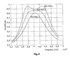
- this will be shown below at the resistor RD, where Fig. 4 shows the transfer function as a function of RD.
- the ultrasound device 10 operates in the receive mode like a (bandpass) filter, which is tunable according to the invention by an adjustment unit (to be explained below).
- the filter should have the widest possible bandwidth, as this determines the response time of the filter in the time domain and thus allows a good distance resolution.
- the bandwidth of the filter should be chosen so that it is not too wide, because otherwise noise and other sources of acoustic interference fall within the transmission range of the filter and are detected as an echo. If this resistor RD is not present, the impedance matching function of the circuit is still present, but optimization of the required bandwidth of the filter can not be achieved without a resistor RD connected in parallel with the transformer.
- the local maxima for the case RD ⁇ RD OPT or the local minima for the case RD> RD OPT are exactly at the resonance frequency of the entire system.
- the curve is right-curved in this case for the case RD ⁇ RD OPT , left-curved for RD> RD OPT .
- this means that the second derivative is less than zero for RD ⁇ RD OPT and greater than zero for RD> RD OPT .
- the second derivative is zero.
- y y - 1 - 2 ⁇ y 0 + y + 1 H 2 used.
- y 0 is the value of the transfer function at resonant frequency.
- Y -1 and Y +1 are two points to the left and right of it.
- the value of RD is increased in small steps until a sign change of the second derivative occurs. It has proved to be reliable, as a starting value for RD the value RO of the transducer too use. In the case of a faulty input and highly detuned oscillating circuits, an upper limit of RD of eg 100 * RO makes sense.
Landscapes
- Engineering & Computer Science (AREA)
- Mechanical Engineering (AREA)
- Apparatuses For Generation Of Mechanical Vibrations (AREA)
- Transducers For Ultrasonic Waves (AREA)
- Measurement Of Resistance Or Impedance (AREA)
Abstract
Die Abstimmeinheit (20) für einen Ultraschallwandler (12) mit Spannungstransformator, der durch ein elektrisches Ersatzschaltbild (14) mit einer eine Serienresonanzfrequenz aufweisenden Reihenschaltung (16) aus einer Induktivität, einer Kapazität und aus einem Widerstand repräsentierbar ist, ist versehen mit einer Parallelresonanzschaltung (26) aus einer Induktivität, einer Kapazität und aus einem Widerstand, wobei die Parallelresonanzschaltung (26) eine Parallelresonanzfrequenz aufweist. Die Induktivität der Parallelresonanzschaltung (26) der Abstimmeinheit (20) bei vorgegebenem Wert für deren Kapazität ist derart gewählt, dass die Parallelresonanzfrequenz der Parallelresonanzschaltung (26) der Abstimmeinheit (20) gleich der Serienresonanzfrequenz der Reihenschaltung des Ultraschallwandlers (12) ist. Die Größe des Widerstandes der Parallelresonanzschaltung (26) der Abstimmeinheit (20) ist bestimmt, dass die zweite mathematische Ableitung des eine resultierende Gesamtresonanzfrequenz aufweisenden Frequenzgangs in einem Frequenzbereich, innerhalb dessen die Serien- bzw. Parallelresonanzfrequenz liegt, im Wesentlichen gleich null ist, wobei der Frequenzbereich eine untere Grenzfrequenz, die um einen ersten Wert von etwa 2 % bis 10 %, insbesondere 2 % bis 8 % bzw. bis 6 % bzw. bis 4 % der Gesamtresonanzfrequenz unterhalb dieser liegt, und eine obere Grenzfrequenz aufweist, die um etwa 2 % bis 10 % der Resonanzfrequenz oberhalb dieser liegt.The tuning unit (20) for an ultrasonic transducer (12) with voltage transformer, which is represented by an equivalent electrical circuit diagram (14) having a series resonance (16) consisting of an inductor, a capacitor and a resistor having a series resonance frequency, is provided with a parallel resonant circuit ( 26) of an inductor, a capacitor and a resistor, wherein the parallel resonant circuit (26) has a parallel resonance frequency. The inductance of the parallel resonant circuit (26) of the tuning unit (20) for a given value for the capacitance is chosen such that the parallel resonance frequency of the parallel resonant circuit (26) of the tuning unit (20) is equal to the series resonant frequency of the series connection of the ultrasonic transducer (12). The magnitude of the resistance of the parallel resonance circuit (26) of the tuning unit (20) is determined to be substantially equal to zero in a frequency range within which the series or parallel resonance frequency is the second mathematical derivative of the frequency response resulting in a total resonance frequency Frequency range, a lower cutoff frequency, which is by a first value of about 2% to 10%, in particular 2% to 8% or to 6% or to 4% of the total resonant frequency below this, and has an upper cutoff frequency, the by about 2 % to 10% of the resonant frequency is above this.
Description
Die Erfindung betrifft ein Verfahren zur Bestimmung von elektrischen Parametern einer Abstimmeinheit für einen Ultraschallwandler. Dieser Ultraschallwandler weist einen Spannungstransformator auf und ist durch ein elektrisches Ersatzschaltbild mit einer eine Serienresonanzfrequenz aufweisenden Reihenschaltung aus einer Induktivität, einer Kapazität und aus einem Widerstand repräsentierbar, wobei die Abstimmeinheit eine Parallelschaltung mit einer Kapazität und einem Widerstand aufweist, die zusammen mit einer parallel geschalteten Induktivität des Spannungstransformators eine eine Parallelresonanzfrequenz aufweisende Parallelresonanzschaltung bildet.The invention relates to a method for determining electrical parameters of a tuning unit for an ultrasonic transducer. This ultrasonic transducer has a voltage transformer and is represented by an equivalent electrical circuit diagram with a series circuit consisting of an inductor, a capacitor and a resistor having a series resonant frequency, wherein the tuning unit has a parallel circuit with a capacitance and a resistor, which together with a parallel-connected inductance of the voltage transformer forms a parallel resonant frequency having a parallel resonant circuit.
Ultraschallvorrichtungen finden beispielsweise Verwendung als Einparkhilfen oder Abstandsmessung für andere Zwecke oder aber auch zur Raumüberwachung. Ultraschallvorrichtungen weisen im Regelfall einen Ultraschallwandler auf, der ein elektrisches Signal in ein akustisches oder umgekehrt wandelt. Ein Ultraschallwandler kann demzufolge sowohl als Sender als auch Empfänger genutzt werden. Darüber hinaus existieren sogenannte Ultraschall-Transducer, die intermittierend als Sender und Empfänger geschaltet werden. Ein Ultraschallwandler weist im Regelfall einen Schwingkreis in Form einer Serienresonanzschaltung auf, die im Ersatzschaltbild des Ultraschallwandlers eine Induktivität, eine Kapazität und einen Widerstand umfasst und eine bauteilbedingte Serienresonanzfrequenz definiert.Ultrasonic devices find use, for example, as parking aids or distance measurement for other purposes or for room monitoring. Ultrasonic devices typically include an ultrasonic transducer that converts an electrical signal into an acoustic or vice versa. An ultrasonic transducer can therefore be used both as transmitter and receiver. In addition, there are so-called ultrasonic transducers, which are switched intermittently as a transmitter and receiver. As a rule, an ultrasound transducer has a resonant circuit in the form of a series resonant circuit which, in the equivalent circuit diagram of the ultrasound transducer, comprises an inductance, a capacitance and a resistor and defines a component-related series resonant frequency.
Zusätzlich weisen die Gesamtsysteme von Ultraschallwandlern mitunter auch Abstimmeinheiten auf, die eine Abstimmkapazität und einen Abstimmwiderstand als Parallelschaltung umfassen. Die Abstimmeinheit ist zwischen einem Spannungswandler und dem Ultraschallwandler selbst geschaltet. Damit liegt parallel zur Abstimmeinheit die durch den Spannungstransformator definierte Induktivität, so dass die Abstimmeinheit zusammen mit dieser Induktivität eine Parallelresonanzschaltung bildet.In addition, the overall systems of ultrasonic transducers sometimes include tuning units that include a tuning capacitance and a tuning resistor in parallel. The tuning unit is connected between a voltage converter and the ultrasonic transducer itself. This is parallel to the tuning unit defined by the voltage transformer Inductance, so that the tuning unit forms a parallel resonance circuit together with this inductance.
Um Ultraschallsignale mit möglichst großer Energie aussenden zu können, legt man im Sendemodus eines Ultraschallwandlers Wert auf eine Leistungsanpassung, d.h. Wert auf die Abstimmung der Resonanzfrequenzen beider Resonanzkreise, die möglichst gleich sein sollten. Der parallele Schwingkreis ist mit Hilfe eines Widerstandes geeignet zu bedämpfen, um den Ausschwingvorgang günstig zu beeinflussen, d.h., um möglichst kurzzeitig nach der Beendigung des Sendebetriebs für den Empfang von Ultraschallsignalen vorbereitet zu sein. Wenn nämlich der Ultraschallwandler noch ausschwingt, während er bereits ankommenden Ultraschallsignalen ausgesetzt ist, können diese ankommenden Ultraschallsignale nicht mit ausreichender Zuverlässigkeit detektiert werden.In order to be able to emit ultrasound signals with as great an energy as possible, in the transmission mode of an ultrasound transducer value is set to a power adaptation, i. Value on the tuning of the resonant frequencies of both resonant circuits, which should be as equal as possible. The parallel resonant circuit is suitably damped by means of a resistor in order to favorably influence the decay process, that is, to be prepared as soon as possible after the end of the transmission operation for the reception of ultrasonic signals. Namely, if the ultrasonic transducer still oscillates while it is already exposed to incoming ultrasonic signals, these incoming ultrasonic signals can not be detected with sufficient reliability.
Aufgabe der Erfindung ist es daher, die elektrischen Parameter einer Abstimmeinheit für einen Ultraschallwandler im Hinblick auf die obigen Kriterien bestimmen zu können.The object of the invention is therefore to be able to determine the electrical parameters of a tuning unit for an ultrasonic transducer with respect to the above criteria.
Zur Lösung dieser Aufgabe wird mit der Erfindung ein Verfahren zur Bestimmung von elektrischen Parametern einer Abstimmeinheit für einen einen Spannungstransformator aufweisenden Ultraschallwandler vorgeschlagen, wobei der Ultraschallwandler durch ein elektrisches Ersatzschaltbild mit einer eine Serienresonanzfrequenz aufweisenden Reihenschaltung aus einer Induktivität, einer Kapazität und aus einem Widerstand repräsentierbar ist und die Abstimmeinheit eine Parallelschaltung mit einer Kapazität und einem (Dämpfungs-)Widerstand aufweist, die zusammen mit einer parallel geschalteten Induktivität des Spannungstransformators einer eine Parallelresonanzfrequenz aufweisende Parallelresonanzschaltung bildet, wobei bei dem erfindungsgemäßen Verfahren
- die Größe des (Dämpfungs-)Widerstandes der Parallelresonanzschaltung der Abstimmeinheit bestimmt wird, indem der Frequenzgang des eine resultierende Gesamtresonanzfrequenz aufweisenden Gesamtsystems aus Abstimmeinheit und Ultraschallwandler bei verschieden großen Werten für den (Dämpfungs-)Widerstand der Parallelresonanzschaltung der Abstimmeinheit ermittelt wird, und zwar entweder messtechnisch oder durch Berechnung oder durch Simulation, wobei als (Dämpfungs-)Widerstand für die Parallelresonanzschaltung der Abstimmeinheit derjenige Wert gewählt wird, bei dem die zweite mathematische Ableitung des Frequenzgangs in einem Frequenzbereich, innerhalb dessen die Gesamtresonanzfrequenz liegt, im Wesentlichen gleich null ist, wobei der Frequenzbereich eine untere Grenzfrequenz, die um einen ersten Wert von etwa 2 % bis 10 %, insbesondere 2 % bis 8 % bzw. bis 6 % bzw. bis 4 % der Gesamtresonanzfrequenz unterhalb dieser liegt, und eine obere Grenzfrequenz aufweist, die um einen zweiten Wert von etwa 2 % bis 10 %, insbesondere 2 % bis 8 % bzw. bis 6 % bzw. bis 4 % der Gesamtresonanzfrequenz oberhalb dieser liegt.
- the magnitude of the (damping) resistance of the parallel resonant circuit of the tuning unit is determined by the frequency response of the overall system having a resultant overall resonant frequency is determined from tuning unit and ultrasonic transducer at different values for the (damping) resistance of the parallel resonant circuit of the tuning unit, either by measurement or by calculation or by simulation, being selected as (damping) resistor for the parallel resonant circuit of the tuning unit that value, wherein the second mathematical derivative of the frequency response is substantially equal to zero in a frequency range within which the total resonance frequency is, the frequency range being a lower cutoff frequency which is a first value of about 2% to 10%, in particular 2% to 8%. or to 6% or 4% of the total resonance frequency is below this, and has an upper cutoff frequency, which by a second value of about 2% to 10%, in particular 2% to 8% or 6% and 4, respectively % of the total resonance frequency is above this.
Der erfindungsgemäße Ansatz geht dahin, das Ausschwingverhalten des Gesamtsystems aus Abstimmeinheit und Ultraschallwandler (einschließlich Spannungstransformator) zu minimieren, so dass die Ausschwingzeit verringert ist. Zu diesem Zweck wird in die Abstimmeinheit ein (Dämpfungs-)Widerstand integriert, der parallel zu einer Abstimmkapazität der Abstimmeinheit geschaltet ist, die beispielsweise die in der Praxis mitunter recht großen Temperaturkoeffizienten des Piezokristalls des Ultraschallwandlers zumindest teilweise kompensiert.The inventive approach is to minimize the decay of the overall system of tuning unit and ultrasonic transducer (including voltage transformer), so that the settling time is reduced. For this purpose, a (damping) resistor is integrated in the tuning unit, which is connected in parallel to a tuning capacity of the tuning unit, which compensates for example, in practice sometimes quite large temperature coefficient of the piezoelectric crystal of the ultrasonic transducer at least partially.
Es hat sich nun gezeigt, dass es hinsichtlich eines guten und insbesondere kurzen Ausschwingverhaltens (Betrachtung im Zeitbereich) von Vorteil ist, wenn sich im Frequenzbereich ein ausgewogener, flacher Frequenzgang ohne Überhöhung gegeben ist. Dabei sollte der Frequenzgang einerseits ausreichend schmalbandig sein, um Störungen des Empfangssignals in einem ausreichenden Maße vermeiden zu können, aber andererseits auch nicht zu schmalbandig sein, da dies die Frequenztoleranz negativ beeinträchtigt, was insbesondere beim Einsatz des Ultraschallwandlers zur Abstandsmessung in der Applikation als z.B. Kfz-Einparkhilfe von Nachteil sein kann.It has now been shown that it is advantageous in terms of a good and in particular short decay behavior (consideration in the time domain), if in the frequency domain, a balanced, flat frequency response without exaggeration is given. The frequency response should on the one hand be sufficiently narrow band in order to avoid interference of the received signal to a sufficient extent, but on the other hand not be too narrow band, as this adversely affects the frequency tolerance, which in particular when using the ultrasonic transducer for distance measurement in the application as eg motor vehicle Parking assistance may be a disadvantage.
In weiterer vorteilhafter Ausgestaltung der Erfindung kann unter dem Aspekt der Leistungsanpassung vorgesehen sein, dass die Induktivität der Parallelresonanzschaltung der Abstimmeinheit bei vorgegebenem Wert für deren Kapazität derart gewählt wird, dass die Parallelresonanzfrequenz der Parallelresonanzschaltung der Abstimmeinheit gleich der Serienresonanzfrequenz der Reihenschaltung des Ultraschallwandlers ist.In a further advantageous embodiment of the invention may be provided from the aspect of power adjustment that the inductance of the parallel resonant circuit of the tuning unit is selected at a predetermined value for the capacity such that the parallel resonance frequency of the parallel resonant circuit of the tuning unit is equal to the series resonant frequency of the series circuit of the ultrasonic transducer.
Wie bereits oben erwähnt, ist die Erfindung insbesondere dann zweckmäßig, wenn die Bestimmung des Widerstandes für den Fall erfolgt, dass der Ultraschallwandler alternierend in einem Sendemoduls zum Aussenden von Ultraschallsignalen in Form von Ultraschallpulsen und insbesondere Ultraschallpulspaketen und in einem Empfangsmodus zum Empfangen von Ultraschallsignalen betrieben wird.As already mentioned above, the invention is particularly useful if the determination of the resistance is made in the event that the ultrasonic transducer is operated alternately in a transmitting module for emitting ultrasonic signals in the form of ultrasonic pulses and in particular ultrasonic pulse packets and in a receiving mode for receiving ultrasonic signals ,
Eine weitere Methode, den Optimal- bzw. Zielwert des Widerstandes der Parallelresonanzschaltung zu ermitteln, besteht darin, den Frequenzgang des Gesamtsystems aus Abstimmeinheit und Ultraschallwandler im Falle des Betriebs des Gesamtsystems in einem Empfangsmodus für einen vorgebbaren Anfangswert des Widerstandes der Parallelresonanzschaltung zu ermitteln und den Wert dieses Widerstandes schrittweise oder kontinuierlich bzw. quasi kontinuierlich solange bis zum Erreichen eines Zielwerts zu verändern, bei dem der Frequenzgang ein Maximum aufweist, bei welchem die zweite Ableitung nach der Frequenz gleich oder im Wesentlichen gleich null ist.Another method for determining the optimum value or resistance of the parallel resonant circuit is to determine the frequency response of the total system of tuning unit and ultrasonic transducer in the case of operation of the entire system in a receiving mode for a predetermined initial value of the resistance of the parallel resonant circuit and the value This resistance gradually or continuously or quasi continuously until a target value is reached, in which the frequency response has a maximum at which the second derivative after the frequency is equal to or substantially equal to zero.
Hierbei kann zweckmäßigerweise vorgesehen sein, dass als Anfangswert für den Widerstand der Parallelresonanzschaltung der Widerstandswert der Serienschaltung des Ersatzschaltbildes des Ultraschallwandlers gewählt wird. Sollte sich bei dieser Vorgehensweise aus welchen Gründen auch immer ein Fehler einstellen, etwa weil die beiden Resonanzschaltungen verstimmt sind, sollte man bei einem oberen Grenzwert für den Widerstand der Parallelresonanzschaltung das Verfahren beenden, wobei dieser obere Grenzwert beispielsweise gleich dem 100-Fachen des Widerstandswerts der Serienschaltung des Ersatzschaltbildes des Ultraschallwandlers ist.It can be expediently provided that the resistance value of the series circuit of the equivalent circuit of the ultrasonic transducer is selected as the initial value for the resistance of the parallel resonant circuit. If, for whatever reason, an error occurs in this procedure, for example because the two resonant circuits are out of tune, then the method should be terminated with an upper limit for the resistance of the parallel resonant circuit, this upper limit being, for example, 100 times the resistance value of the Series connection of the equivalent circuit of the ultrasonic transducer is.
In weiterer zweckmäßiger Ausgestaltung der Erfindung kann vorgesehen sein, dass die Veränderung des Werts des Widerstandes der Parallelresonanzschaltung dahingehend variiert wird, dass der Grad der Veränderung des Werts dieses Widerstandes proportional zum Grad der vorherigen Veränderung des Frequenzgangs im Bereich des Maximums gewählt wird. Schließlich kann auch vorgesehen sein, dass der Zielwert für den Widerstand der Parallelresonanzschaltung durch sukzessive Approximation ermittelt wird.In a further advantageous embodiment of the invention can be provided that the change in the value of the resistance of the parallel resonant circuit is varied so that the degree of change in the value of this resistor is selected in proportion to the degree of the previous change in the frequency response in the range of the maximum. Finally, it can also be provided that the target value for the resistance of the parallel resonance circuit is determined by successive approximation.
Die oben genannte Aufgabe wird u.a. auch durch eine Abstimmeinheit für einen Ultraschallwandler mit Spannungstransformator gelöst, der durch ein elektrisches Ersatzschaltbild mit einer eine Serienresonanzfrequenz aufweisenden Reihenschaltung aus einer Induktivität, einer Kapazität und aus einem Widerstand repräsentierbar ist, wobei diese Abstimmeinheit versehen ist mit
- einer Parallelresonanzschaltung aus einer Induktivität, einer Kapazität und aus einem Widerstand, wobei die Parallelresonanzschaltung eine Parallelresonanzfrequenz aufweist,
- wobei zweckmäßigerweise gilt, dass die Induktivität der Parallelresonanzschaltung der Abstimmeinheit bei vorgegebenem Wert für deren Kapazität derart gewählt ist, dass die Parallelresonanzfrequenz der Parallelresonanzschaltung der Abstimmeinheit gleich der Serienresonanzfrequenz der Reihenschaltung des Ultraschallwandlers ist, und
- wobei die Größe des Widerstandes der Parallelresonanzschaltung der Abstimmeinheit bestimmt ist, dass die zweite mathematische Ableitung des eine resultierende Gesamtresonanzfrequenz aufweisenden Frequenzgangs in einem Frequenzbereich, innerhalb dessen die Serien- bzw. Parallelresonanzfrequenz liegt, im Wesentlichen gleich null ist, wobei der Frequenzbereich eine untere Grenzfrequenz, die um einen ersten Wert von etwa 2 % bis 10 %, insbesondere 2 % bis 8 % bzw. bis 6 % bzw. bis 4 % der Gesamtresonanzfrequenz unterhalb dieser liegt, und eine obere Grenzfrequenz aufweist, die um etwa 2 % bis 10 % der Resonanzfrequenz oberhalb dieser liegt.
- a parallel resonant circuit of an inductor, a capacitor and a resistor, the parallel resonant circuit having a parallel resonant frequency,
- wherein expediently applies that the inductance of the parallel resonant circuit of the tuning unit is selected at a predetermined value for the capacitance such that the parallel resonance frequency of the parallel resonant circuit of the tuning unit is equal to the series resonant frequency of the series circuit of the ultrasonic transducer, and
- wherein the magnitude of the resistance of the parallel resonance circuit of the tuning unit is determined to be substantially equal to zero, the second mathematical derivative of the frequency response having a resultant total resonance frequency in a frequency range within which the series or parallel resonance frequency is, the frequency range being a lower limit frequency, which is a first value of about 2% to 10%, in particular 2% to 8% or to 6% or 4% of the total resonance frequency below this, and has an upper cutoff frequency which is about 2% to 10% of Resonance frequency is above this.
Bei dieser Abstimmeinheit kann ferner mit Vorteil vorgesehen sein, dass die Induktivität der Parallelresonanzschaltung der Abstimmeinheit bei vorgegebenem Wert für deren Kapazität derart gewählt ist, dass die Parallelresonanzfrequenz der Parallelresonanzschaltung der Abstimmeinheit gleich der Serienresonanzfrequenz der Reihenschaltung des Ultraschallwandlers ist.In this tuning unit can also be advantageously provided that the inductance of the parallel resonant circuit of the tuning unit is selected at a predetermined value for the capacity such that the parallel resonance frequency of the parallel resonant circuit of the tuning unit is equal to the series resonant frequency of the series circuit of the ultrasonic transducer.
Schließlich kann auch diese Abstimmeinheit bei einem Ultraschallwandler eingesetzt werden, der alternierend in einem Sendemoduls zum Aussenden von Ultraschallsignalen in Form von Ultraschallpulsen und insbesondere Ultraschallpulspaketen und in einem Empfangsmodus zum Empfangen von Ultraschallsignalen betreibbar ist.Finally, this tuning unit can also be used in an ultrasound transducer which can be operated alternately in a transmission module for emitting ultrasound signals in the form of ultrasound pulses and in particular ultrasound pulse packets and in a reception mode for receiving ultrasound signals.
Die Erfindung wird nachfolgend anhand eines Ausführungsbeispiels sowie unter Bezugnahme auf die Zeichnung näher beschrieben. Im Einzelnen zeigen dabei:
- Fign. 1 bis 3
- verschiedene Darstellungen der elektrischen Beschaltung einer Ultraschallvorrichtung bei deren Betrieb im Empfangs- und im Sendemodus sowie zur Darstellung der Impedanzfunktionsermittlung, und
- Fig. 4
- die Übertragungsfunktion einer für den Empfangsmodus optimierten Ultraschallvorrichtung in Abhängigkeit von RD.
- FIGS. 1 to 3
- various representations of the electrical wiring of an ultrasonic device in their operation in the receive and in the transmission mode and for representing the impedance function determination, and
- Fig. 4
- the transfer function of an optimized for the receiving mode ultrasonic device as a function of RD.
Ultraschallwandler 12 bzw. -Transducer werden in der Regel mittels eines Spannungstransformators angesteuert. Die Induktivität wird dabei so ausgelegt, dass die Resonanzfrequenz zusammen mit der parallel geschalteten (parasitären) Kapazität des Piezokristalls gleich der Resonanzfrequenz des Transducers ist. Mit Hilfe eines zusätzlichen, parallel geschalteten (Dämpfungs)Widerstandes RD kann das Ausschwingverhalten der gesamten Anordnung minimiert werden, indem der parallele Schwingkreis mit Hilfe dieses Widerstandes bei geeigneter Wahl "bedämpft" wird. Eine analytische Lösung für dieses Problem ist mit vertretbarem Aufwand (wenn überhaupt) kaum möglich.
Daher wird nachfolgend ein Verfahren vorgestellt, mit dem sich der Widerstand RD schnell und effizient bestimmen lässt.Therefore, a method that can be used to determine the resistance RD quickly and efficiently is presented below.
Die durch die Ultraschallvorrichtung 10 gegebene Impedanz setzt sich aus der Verschaltung der zuvor genannten Elemente zusammen, wie es in
Aus den
Anhand von
Es hat sich gezeigt, dass für den Fall RD=RDOPT in der Praxis die Ausschwingzeit nahezu minimal ist. Im Folgenden wird kurz ein Ausführungsbeispiel der erfindungsgemäßen Vorgehensweise skizziert.It has been found that for the case RD = RD OPT in practice, the settling time is almost minimal. In the following, an embodiment of the procedure according to the invention is briefly outlined.
Die lokalen Maxima für den Fall RD<RDOPT bzw. die lokalen Minima für den Fall RD>RDOPT liegen genau bei der Resonanzfrequenz des Gesamtsystems. Der Kurvenverlauf ist in diesem Punkt für den Fall RD<RDOPT rechtsgekrümmt, für RD>RDOPT linksgekrümmt. Mathematisch bedeutet das, dass die zweite Ableitung kleiner null für RD<RDOPT und größer null für RD>RDOPT ist. Bei RD=RDOPT ist die zweite Ableitung gleich null. Grundsätzlich ist es möglich, die zweite Ableitung des Betrags der Übertragungsfunktion analytisch zu bestimmen. Dies ist aber sehr umfangreich. Hier wird die numerische Bestimmung der zweiten Ableitung mit Hilfe einer numerischen Näherung z.B. 
verwendet. Dabei ist y0 der Wert der Übertragungsfunktion bei Resonanzfrequenz. Y-1 und Y+1 sind zwei Punkte jeweils links und rechts davon.The local maxima for the case RD <RD OPT or the local minima for the case RD> RD OPT are exactly at the resonance frequency of the entire system. The curve is right-curved in this case for the case RD <RD OPT , left-curved for RD> RD OPT . Mathematically, this means that the second derivative is less than zero for RD <RD OPT and greater than zero for RD> RD OPT . For RD = RD OPT , the second derivative is zero. In principle, it is possible to analytically determine the second derivative of the amount of the transfer function. This is very extensive. Here, the numerical determination of the second derivative using a numerical approximation, for example
used. Here y 0 is the value of the transfer function at resonant frequency. Y -1 and Y +1 are two points to the left and right of it.
Ausgehend von einem Startwert wird der Wert von RD in kleinen Schritten erhöht bis ein Vorzeichenwechsel der zweiten Ableitung auftritt. Es hat sich als zuverlässig erwiesen, als Startwert für RD den Wert RO des Transducers zu verwenden. Für den Fall einer fehlerhaften Eingabe und stark gegeneinander verstimmter Schwingkreise, ist eine obere Schranke für RD von z.B. 100*RO sinnvoll.Starting from a starting value, the value of RD is increased in small steps until a sign change of the second derivative occurs. It has proved to be reliable, as a starting value for RD the value RO of the transducer too use. In the case of a faulty input and highly detuned oscillating circuits, an upper limit of RD of eg 100 * RO makes sense.
- 1010
- Ultraschallvorrichtungultrasound device
- 1212
- Ultraschallwandlerultrasound transducer
- 1414
- elektrisches Ersatzschaltbildelectrical equivalent circuit diagram
- 1616
- Reihenschaltungseries connection
- 1818
- Piezokristallpiezo crystal
- 2020
- Abstimmeinheittuning
- 2222
- Parallelschaltungparallel connection
- 2424
- Spannungstransformatorvoltage transformer
- 2626
- ParallelresonanzschaltungParallel resonant circuit
- CADDCADD
- (Abgleich-)Kapazität(Balancing) Capacity
- LTLT
- Induktivität des SpannungstransformatorsInductance of the voltage transformer
- RDRD
- (Dämpfungs-)Widerstand(Damping) resistor
- C0C0
- parasitäre Kapazität des Ultraschallwandlersparasitic capacitance of the ultrasonic transducer
- L0L0
- parasitäre Induktivität des Ultraschallwandlersparasitic inductance of the ultrasonic transducer
- R0R0
- (Innen-)Widerstand des Ultraschallwandlers(Internal) resistance of the ultrasonic transducer
Claims (10)
Priority Applications (1)
| Application Number | Priority Date | Filing Date | Title |
|---|---|---|---|
| EP13196307.6A EP2881181A1 (en) | 2013-12-09 | 2013-12-09 | Method for determining electrical parameters of a tuning unit for an ultrasonic transducer |
Applications Claiming Priority (1)
| Application Number | Priority Date | Filing Date | Title |
|---|---|---|---|
| EP13196307.6A EP2881181A1 (en) | 2013-12-09 | 2013-12-09 | Method for determining electrical parameters of a tuning unit for an ultrasonic transducer |
Publications (1)
| Publication Number | Publication Date |
|---|---|
| EP2881181A1 true EP2881181A1 (en) | 2015-06-10 |
Family
ID=49753032
Family Applications (1)
| Application Number | Title | Priority Date | Filing Date |
|---|---|---|---|
| EP13196307.6A Withdrawn EP2881181A1 (en) | 2013-12-09 | 2013-12-09 | Method for determining electrical parameters of a tuning unit for an ultrasonic transducer |
Country Status (1)
| Country | Link |
|---|---|
| EP (1) | EP2881181A1 (en) |
Cited By (6)
| Publication number | Priority date | Publication date | Assignee | Title |
|---|---|---|---|---|
| CN109075760A (en) * | 2016-04-25 | 2018-12-21 | 南洋理工大学 | Vltrasonic device, forming method and its control method |
| CN109877027A (en) * | 2019-04-03 | 2019-06-14 | 淄博宇声计量科技有限公司 | A kind of impedance matching of ultrasonic transducer and transmission-receiving function switching circuit |
| US10585178B2 (en) | 2015-10-21 | 2020-03-10 | Semiconductor Componenents Industries, Llc | Piezo transducer controller and method having adaptively-tuned linear damping |
| CN111781470A (en) * | 2020-06-05 | 2020-10-16 | 国网浙江省电力有限公司电力科学研究院 | A High-frequency Circuit Equivalent Method of Current Transformer |
| CN113594351A (en) * | 2021-07-13 | 2021-11-02 | 杭州电子科技大学 | Piezoelectric transducer with adjustable resonant frequency and frequency adjusting control system thereof |
| DE102017120682B4 (en) * | 2016-09-08 | 2026-02-05 | Hyundai Mobis Co., Ltd. | DEVICE AND METHOD FOR OPERATING AN ULTRASOUND SENSOR |
Citations (6)
| Publication number | Priority date | Publication date | Assignee | Title |
|---|---|---|---|---|
| US3144764A (en) * | 1958-10-01 | 1964-08-18 | Republic Steel Corp | Ultrasonic inspection system |
| JP2001086587A (en) * | 1999-09-10 | 2001-03-30 | Tokimec Inc | Ultrasonic wave transducer |
| US20070121969A1 (en) * | 2005-11-15 | 2007-05-31 | Seiko Epson Corporation | Electrostatic transducer, driving circuit of capacitive load, method for setting circuit constant, ultrasonic speaker, display device and directional acoustic system |
| US20070121970A1 (en) * | 2005-11-25 | 2007-05-31 | Seiko Epson Corporation | Electrostatic transducer, ultrasonic speaker, driving circuit of capacitive load, method of setting circuit constant, display device, and directional sound system |
| US20110261652A1 (en) * | 2010-04-26 | 2011-10-27 | Pavel Horsky | Self-tuning acoustic measurement system |
| US20130093522A1 (en) * | 2011-10-12 | 2013-04-18 | Atmel Corporation | High accuracy rc oscillator |
-
2013
- 2013-12-09 EP EP13196307.6A patent/EP2881181A1/en not_active Withdrawn
Patent Citations (6)
| Publication number | Priority date | Publication date | Assignee | Title |
|---|---|---|---|---|
| US3144764A (en) * | 1958-10-01 | 1964-08-18 | Republic Steel Corp | Ultrasonic inspection system |
| JP2001086587A (en) * | 1999-09-10 | 2001-03-30 | Tokimec Inc | Ultrasonic wave transducer |
| US20070121969A1 (en) * | 2005-11-15 | 2007-05-31 | Seiko Epson Corporation | Electrostatic transducer, driving circuit of capacitive load, method for setting circuit constant, ultrasonic speaker, display device and directional acoustic system |
| US20070121970A1 (en) * | 2005-11-25 | 2007-05-31 | Seiko Epson Corporation | Electrostatic transducer, ultrasonic speaker, driving circuit of capacitive load, method of setting circuit constant, display device, and directional sound system |
| US20110261652A1 (en) * | 2010-04-26 | 2011-10-27 | Pavel Horsky | Self-tuning acoustic measurement system |
| US20130093522A1 (en) * | 2011-10-12 | 2013-04-18 | Atmel Corporation | High accuracy rc oscillator |
Cited By (9)
| Publication number | Priority date | Publication date | Assignee | Title |
|---|---|---|---|---|
| US10585178B2 (en) | 2015-10-21 | 2020-03-10 | Semiconductor Componenents Industries, Llc | Piezo transducer controller and method having adaptively-tuned linear damping |
| CN109075760A (en) * | 2016-04-25 | 2018-12-21 | 南洋理工大学 | Vltrasonic device, forming method and its control method |
| CN109075760B (en) * | 2016-04-25 | 2024-04-02 | 南洋理工大学 | Ultrasonic device, method of forming the same, and method of controlling the same |
| DE102017120682B4 (en) * | 2016-09-08 | 2026-02-05 | Hyundai Mobis Co., Ltd. | DEVICE AND METHOD FOR OPERATING AN ULTRASOUND SENSOR |
| CN109877027A (en) * | 2019-04-03 | 2019-06-14 | 淄博宇声计量科技有限公司 | A kind of impedance matching of ultrasonic transducer and transmission-receiving function switching circuit |
| CN109877027B (en) * | 2019-04-03 | 2024-01-26 | 淄博宇声计量科技有限公司 | Impedance matching and receiving and transmitting function switching circuit of ultrasonic transducer |
| CN111781470A (en) * | 2020-06-05 | 2020-10-16 | 国网浙江省电力有限公司电力科学研究院 | A High-frequency Circuit Equivalent Method of Current Transformer |
| CN111781470B (en) * | 2020-06-05 | 2023-05-16 | 国网浙江省电力有限公司电力科学研究院 | High-frequency circuit equivalent method of current transformer |
| CN113594351A (en) * | 2021-07-13 | 2021-11-02 | 杭州电子科技大学 | Piezoelectric transducer with adjustable resonant frequency and frequency adjusting control system thereof |
Similar Documents
| Publication | Publication Date | Title |
|---|---|---|
| EP2881181A1 (en) | Method for determining electrical parameters of a tuning unit for an ultrasonic transducer | |
| EP2984503B1 (en) | Method for measurement by means of ultrasound, in particular as a parking aid for vehicles, and ultrasound measuring systems | |
| EP2743725B1 (en) | Ultrasound device | |
| DE2005918A1 (en) | Filter circuit | |
| EP1837893A1 (en) | Measuring device of an HF-plasma system | |
| DE2404878A1 (en) | ACOUSTIC SURFACE CONVERTER | |
| DE2724437C2 (en) | ||
| DE1566035A1 (en) | Acoustic device | |
| DE1953826A1 (en) | Energy transmission device | |
| DE2803225A1 (en) | TEMPERATURE SENSING SYSTEM | |
| DE102010003624A1 (en) | Method for detecting fault of ultrasonic transducer utilized for detecting distance of car, involves comparing release time duration with another release time duration so as to detect fault in transducer | |
| DE1957765A1 (en) | Bridge filter | |
| EP2243219B1 (en) | Digital optimal filter for periodically alternating signals | |
| EP1736748B1 (en) | Method of processing the output signal of a mesuring transducer and force measuring device for carrying out the method. | |
| DE102014202144B4 (en) | For vehicles intended ultrasonic parking aid with charge pump circuit, and method for operating the parking aid | |
| EP1458216B1 (en) | Device and method for adaption of microphones in a hearing aid | |
| WO2012100959A1 (en) | Cylindrical device, pulse wave measurement system and method for measuring a pulse wave speed | |
| EP3537177B1 (en) | Device and method for transducer-free control of an ultrasonic transducer | |
| DE102022115293B4 (en) | Hybrid filter circuit and system with hybrid filter circuit | |
| DE10103481A1 (en) | Digital quasi peak detector for simulation of the subjective perception of the human ear or eye to interference impulses in audible or visual signals respectively has wide frequency range and is time and temperature stable | |
| WO2007082834A1 (en) | Measuring device, in particular distance measuring device | |
| DE504173C (en) | Method and device for monitoring or measuring the amplification capacity of electrical amplifiers | |
| EP2725353B1 (en) | Method for automatic operating frequency work point adjustment of an ultrasound detection device | |
| DE2214252C3 (en) | Band filters for electrical oscillations | |
| AT510244B1 (en) | FAST MEASUREMENT PROCEDURE FOR DETECTING OFW SENSOR DATA |
Legal Events
| Date | Code | Title | Description |
|---|---|---|---|
| PUAI | Public reference made under article 153(3) epc to a published international application that has entered the european phase |
Free format text: ORIGINAL CODE: 0009012 |
|
| 17P | Request for examination filed |
Effective date: 20150417 |
|
| AK | Designated contracting states |
Kind code of ref document: A1 Designated state(s): AL AT BE BG CH CY CZ DE DK EE ES FI FR GB GR HR HU IE IS IT LI LT LU LV MC MK MT NL NO PL PT RO RS SE SI SK SM TR |
|
| RAP1 | Party data changed (applicant data changed or rights of an application transferred) |
Owner name: ELMOS SEMICONDUCTOR AKTIENGESELLSCHAFT |
|
| RAP1 | Party data changed (applicant data changed or rights of an application transferred) |
Owner name: ELMOS SEMICONDUCTOR AKTIENGESELLSCHAFT |
|
| 17Q | First examination report despatched |
Effective date: 20160314 |
|
| STAA | Information on the status of an ep patent application or granted ep patent |
Free format text: STATUS: EXAMINATION IS IN PROGRESS |
|
| STAA | Information on the status of an ep patent application or granted ep patent |
Free format text: STATUS: THE APPLICATION IS DEEMED TO BE WITHDRAWN |
|
| 18D | Application deemed to be withdrawn |
Effective date: 20170315 |