EP2881177B1 - Electrostatic precipitator - Google Patents
Electrostatic precipitator Download PDFInfo
- Publication number
- EP2881177B1 EP2881177B1 EP13825156.6A EP13825156A EP2881177B1 EP 2881177 B1 EP2881177 B1 EP 2881177B1 EP 13825156 A EP13825156 A EP 13825156A EP 2881177 B1 EP2881177 B1 EP 2881177B1
- Authority
- EP
- European Patent Office
- Prior art keywords
- discharge
- plate
- electrode
- particulate matter
- gas
- Prior art date
- Legal status (The legal status is an assumption and is not a legal conclusion. Google has not performed a legal analysis and makes no representation as to the accuracy of the status listed.)
- Active
Links
Images


Classifications
-
- B—PERFORMING OPERATIONS; TRANSPORTING
- B03—SEPARATION OF SOLID MATERIALS USING LIQUIDS OR USING PNEUMATIC TABLES OR JIGS; MAGNETIC OR ELECTROSTATIC SEPARATION OF SOLID MATERIALS FROM SOLID MATERIALS OR FLUIDS; SEPARATION BY HIGH-VOLTAGE ELECTRIC FIELDS
- B03C—MAGNETIC OR ELECTROSTATIC SEPARATION OF SOLID MATERIALS FROM SOLID MATERIALS OR FLUIDS; SEPARATION BY HIGH-VOLTAGE ELECTRIC FIELDS
- B03C3/00—Separating dispersed particles from gases or vapour, e.g. air, by electrostatic effect
- B03C3/02—Plant or installations having external electricity supply
- B03C3/04—Plant or installations having external electricity supply dry type
- B03C3/14—Plant or installations having external electricity supply dry type characterised by the additional use of mechanical effects, e.g. gravity
- B03C3/15—Centrifugal forces
-
- B—PERFORMING OPERATIONS; TRANSPORTING
- B03—SEPARATION OF SOLID MATERIALS USING LIQUIDS OR USING PNEUMATIC TABLES OR JIGS; MAGNETIC OR ELECTROSTATIC SEPARATION OF SOLID MATERIALS FROM SOLID MATERIALS OR FLUIDS; SEPARATION BY HIGH-VOLTAGE ELECTRIC FIELDS
- B03C—MAGNETIC OR ELECTROSTATIC SEPARATION OF SOLID MATERIALS FROM SOLID MATERIALS OR FLUIDS; SEPARATION BY HIGH-VOLTAGE ELECTRIC FIELDS
- B03C3/00—Separating dispersed particles from gases or vapour, e.g. air, by electrostatic effect
- B03C3/017—Combinations of electrostatic separation with other processes, not otherwise provided for
-
- B—PERFORMING OPERATIONS; TRANSPORTING
- B03—SEPARATION OF SOLID MATERIALS USING LIQUIDS OR USING PNEUMATIC TABLES OR JIGS; MAGNETIC OR ELECTROSTATIC SEPARATION OF SOLID MATERIALS FROM SOLID MATERIALS OR FLUIDS; SEPARATION BY HIGH-VOLTAGE ELECTRIC FIELDS
- B03C—MAGNETIC OR ELECTROSTATIC SEPARATION OF SOLID MATERIALS FROM SOLID MATERIALS OR FLUIDS; SEPARATION BY HIGH-VOLTAGE ELECTRIC FIELDS
- B03C3/00—Separating dispersed particles from gases or vapour, e.g. air, by electrostatic effect
- B03C3/02—Plant or installations having external electricity supply
- B03C3/04—Plant or installations having external electricity supply dry type
- B03C3/06—Plant or installations having external electricity supply dry type characterised by presence of stationary tube electrodes
-
- B—PERFORMING OPERATIONS; TRANSPORTING
- B03—SEPARATION OF SOLID MATERIALS USING LIQUIDS OR USING PNEUMATIC TABLES OR JIGS; MAGNETIC OR ELECTROSTATIC SEPARATION OF SOLID MATERIALS FROM SOLID MATERIALS OR FLUIDS; SEPARATION BY HIGH-VOLTAGE ELECTRIC FIELDS
- B03C—MAGNETIC OR ELECTROSTATIC SEPARATION OF SOLID MATERIALS FROM SOLID MATERIALS OR FLUIDS; SEPARATION BY HIGH-VOLTAGE ELECTRIC FIELDS
- B03C3/00—Separating dispersed particles from gases or vapour, e.g. air, by electrostatic effect
- B03C3/02—Plant or installations having external electricity supply
- B03C3/04—Plant or installations having external electricity supply dry type
- B03C3/08—Plant or installations having external electricity supply dry type characterised by presence of stationary flat electrodes arranged with their flat surfaces parallel to the gas stream
-
- B—PERFORMING OPERATIONS; TRANSPORTING
- B03—SEPARATION OF SOLID MATERIALS USING LIQUIDS OR USING PNEUMATIC TABLES OR JIGS; MAGNETIC OR ELECTROSTATIC SEPARATION OF SOLID MATERIALS FROM SOLID MATERIALS OR FLUIDS; SEPARATION BY HIGH-VOLTAGE ELECTRIC FIELDS
- B03C—MAGNETIC OR ELECTROSTATIC SEPARATION OF SOLID MATERIALS FROM SOLID MATERIALS OR FLUIDS; SEPARATION BY HIGH-VOLTAGE ELECTRIC FIELDS
- B03C3/00—Separating dispersed particles from gases or vapour, e.g. air, by electrostatic effect
- B03C3/02—Plant or installations having external electricity supply
- B03C3/04—Plant or installations having external electricity supply dry type
- B03C3/09—Plant or installations having external electricity supply dry type characterised by presence of stationary flat electrodes arranged with their flat surfaces at right angles to the gas stream
-
- B—PERFORMING OPERATIONS; TRANSPORTING
- B03—SEPARATION OF SOLID MATERIALS USING LIQUIDS OR USING PNEUMATIC TABLES OR JIGS; MAGNETIC OR ELECTROSTATIC SEPARATION OF SOLID MATERIALS FROM SOLID MATERIALS OR FLUIDS; SEPARATION BY HIGH-VOLTAGE ELECTRIC FIELDS
- B03C—MAGNETIC OR ELECTROSTATIC SEPARATION OF SOLID MATERIALS FROM SOLID MATERIALS OR FLUIDS; SEPARATION BY HIGH-VOLTAGE ELECTRIC FIELDS
- B03C3/00—Separating dispersed particles from gases or vapour, e.g. air, by electrostatic effect
- B03C3/02—Plant or installations having external electricity supply
- B03C3/04—Plant or installations having external electricity supply dry type
- B03C3/12—Plant or installations having external electricity supply dry type characterised by separation of ionising and collecting stations
-
- B—PERFORMING OPERATIONS; TRANSPORTING
- B03—SEPARATION OF SOLID MATERIALS USING LIQUIDS OR USING PNEUMATIC TABLES OR JIGS; MAGNETIC OR ELECTROSTATIC SEPARATION OF SOLID MATERIALS FROM SOLID MATERIALS OR FLUIDS; SEPARATION BY HIGH-VOLTAGE ELECTRIC FIELDS
- B03C—MAGNETIC OR ELECTROSTATIC SEPARATION OF SOLID MATERIALS FROM SOLID MATERIALS OR FLUIDS; SEPARATION BY HIGH-VOLTAGE ELECTRIC FIELDS
- B03C3/00—Separating dispersed particles from gases or vapour, e.g. air, by electrostatic effect
- B03C3/34—Constructional details or accessories or operation thereof
- B03C3/36—Controlling flow of gases or vapour
- B03C3/368—Controlling flow of gases or vapour by other than static mechanical means, e.g. internal ventilator or recycler
-
- B—PERFORMING OPERATIONS; TRANSPORTING
- B03—SEPARATION OF SOLID MATERIALS USING LIQUIDS OR USING PNEUMATIC TABLES OR JIGS; MAGNETIC OR ELECTROSTATIC SEPARATION OF SOLID MATERIALS FROM SOLID MATERIALS OR FLUIDS; SEPARATION BY HIGH-VOLTAGE ELECTRIC FIELDS
- B03C—MAGNETIC OR ELECTROSTATIC SEPARATION OF SOLID MATERIALS FROM SOLID MATERIALS OR FLUIDS; SEPARATION BY HIGH-VOLTAGE ELECTRIC FIELDS
- B03C3/00—Separating dispersed particles from gases or vapour, e.g. air, by electrostatic effect
- B03C3/34—Constructional details or accessories or operation thereof
- B03C3/40—Electrode constructions
- B03C3/41—Ionising-electrodes
-
- B—PERFORMING OPERATIONS; TRANSPORTING
- B03—SEPARATION OF SOLID MATERIALS USING LIQUIDS OR USING PNEUMATIC TABLES OR JIGS; MAGNETIC OR ELECTROSTATIC SEPARATION OF SOLID MATERIALS FROM SOLID MATERIALS OR FLUIDS; SEPARATION BY HIGH-VOLTAGE ELECTRIC FIELDS
- B03C—MAGNETIC OR ELECTROSTATIC SEPARATION OF SOLID MATERIALS FROM SOLID MATERIALS OR FLUIDS; SEPARATION BY HIGH-VOLTAGE ELECTRIC FIELDS
- B03C3/00—Separating dispersed particles from gases or vapour, e.g. air, by electrostatic effect
- B03C3/34—Constructional details or accessories or operation thereof
- B03C3/40—Electrode constructions
- B03C3/45—Collecting-electrodes
- B03C3/47—Collecting-electrodes flat, e.g. plates, discs, gratings
-
- B—PERFORMING OPERATIONS; TRANSPORTING
- B03—SEPARATION OF SOLID MATERIALS USING LIQUIDS OR USING PNEUMATIC TABLES OR JIGS; MAGNETIC OR ELECTROSTATIC SEPARATION OF SOLID MATERIALS FROM SOLID MATERIALS OR FLUIDS; SEPARATION BY HIGH-VOLTAGE ELECTRIC FIELDS
- B03C—MAGNETIC OR ELECTROSTATIC SEPARATION OF SOLID MATERIALS FROM SOLID MATERIALS OR FLUIDS; SEPARATION BY HIGH-VOLTAGE ELECTRIC FIELDS
- B03C3/00—Separating dispersed particles from gases or vapour, e.g. air, by electrostatic effect
- B03C3/34—Constructional details or accessories or operation thereof
- B03C3/40—Electrode constructions
- B03C3/45—Collecting-electrodes
- B03C3/51—Catch- space electrodes, e.g. slotted-box form
-
- B—PERFORMING OPERATIONS; TRANSPORTING
- B03—SEPARATION OF SOLID MATERIALS USING LIQUIDS OR USING PNEUMATIC TABLES OR JIGS; MAGNETIC OR ELECTROSTATIC SEPARATION OF SOLID MATERIALS FROM SOLID MATERIALS OR FLUIDS; SEPARATION BY HIGH-VOLTAGE ELECTRIC FIELDS
- B03C—MAGNETIC OR ELECTROSTATIC SEPARATION OF SOLID MATERIALS FROM SOLID MATERIALS OR FLUIDS; SEPARATION BY HIGH-VOLTAGE ELECTRIC FIELDS
- B03C3/00—Separating dispersed particles from gases or vapour, e.g. air, by electrostatic effect
- B03C3/34—Constructional details or accessories or operation thereof
- B03C3/74—Cleaning the electrodes
-
- B—PERFORMING OPERATIONS; TRANSPORTING
- B03—SEPARATION OF SOLID MATERIALS USING LIQUIDS OR USING PNEUMATIC TABLES OR JIGS; MAGNETIC OR ELECTROSTATIC SEPARATION OF SOLID MATERIALS FROM SOLID MATERIALS OR FLUIDS; SEPARATION BY HIGH-VOLTAGE ELECTRIC FIELDS
- B03C—MAGNETIC OR ELECTROSTATIC SEPARATION OF SOLID MATERIALS FROM SOLID MATERIALS OR FLUIDS; SEPARATION BY HIGH-VOLTAGE ELECTRIC FIELDS
- B03C2201/00—Details of magnetic or electrostatic separation
- B03C2201/10—Ionising electrode with two or more serrated ends or sides
-
- B—PERFORMING OPERATIONS; TRANSPORTING
- B03—SEPARATION OF SOLID MATERIALS USING LIQUIDS OR USING PNEUMATIC TABLES OR JIGS; MAGNETIC OR ELECTROSTATIC SEPARATION OF SOLID MATERIALS FROM SOLID MATERIALS OR FLUIDS; SEPARATION BY HIGH-VOLTAGE ELECTRIC FIELDS
- B03C—MAGNETIC OR ELECTROSTATIC SEPARATION OF SOLID MATERIALS FROM SOLID MATERIALS OR FLUIDS; SEPARATION BY HIGH-VOLTAGE ELECTRIC FIELDS
- B03C2201/00—Details of magnetic or electrostatic separation
- B03C2201/12—Cleaning the device by burning the trapped particles
-
- B—PERFORMING OPERATIONS; TRANSPORTING
- B03—SEPARATION OF SOLID MATERIALS USING LIQUIDS OR USING PNEUMATIC TABLES OR JIGS; MAGNETIC OR ELECTROSTATIC SEPARATION OF SOLID MATERIALS FROM SOLID MATERIALS OR FLUIDS; SEPARATION BY HIGH-VOLTAGE ELECTRIC FIELDS
- B03C—MAGNETIC OR ELECTROSTATIC SEPARATION OF SOLID MATERIALS FROM SOLID MATERIALS OR FLUIDS; SEPARATION BY HIGH-VOLTAGE ELECTRIC FIELDS
- B03C2201/00—Details of magnetic or electrostatic separation
- B03C2201/30—Details of magnetic or electrostatic separation for use in or with vehicles
Definitions
- the present invention relates to an electrostatic precipitator that removes particulate matter (PM) from a PM-containing gas such as exhaust gas, for example, of an internal combustion engine, which includes the PM.
- PM particulate matter
- Exhaust gas discharged from an internal combustion engine includes hazardous substances such as NOx, SOx, and also PM including carbon as the main component.
- the PM that has penetrated into a human body as a result of breathing is known to cause various health problems, and it is desirable to develop a PM collecting apparatus with high collection efficiency.
- a method in which a filter is disposed in an exhaust gas duct can be used in such a PM removing apparatus, but the filter can be easily clogged and has a large pressure loss.
- an electrostatic precipitator does not have a risk of clogging and has a small pressure loss, and therefore can be effectively installed in the exhaust gas duct of an internal combustion engine.
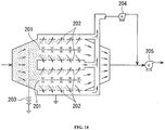
- a dust collecting apparatus comprising a discharge electrode 201 in a flow of gas including a particulate matter, a filtration device 202 provided opposite the discharge electrode 201, a high-voltage power source 203 that applies a high voltage between the discharge electrode 201 and the filtration device 202, an extraction blower 204 that adjusts the gas flow passing through the filtration device 202, and a main blower 205 that sucks in the exhaust gas, for example, as shown in FIG. 14 , is known as a PM collecting apparatus of such an electric dust collection system (see, for example, Patent Document 1).
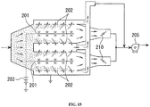
- a dust collecting apparatus is also known in which the extraction blower 204 is omitted, a gas outlet is divided in two, and a damper 210 for pressure loss adjustment is provided in each gas outlet instead of the blower, as shown in FIG. 15 (see, for example, Patent Document 1).
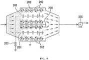
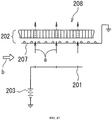
- a dust removing apparatus which includes a discharge electrode 201 in a gas flow including a particulate matter, a filtration device 202 having a counter electrode 207 disposed opposite the discharge electrode 201, a high-voltage power source 203 that applies a high voltage between the discharge electrode 201 and the filtration device 202, and a closed space 208 provided inside the filtration means 202 or at the rear surface thereof, as shown in FIGS. 16 and 17 (see, for example, Patent Document 2).
- JP 2007 100635 A describes a discharge electrode charging particulate matter in exhaust gas that is provided at a center part of a casing, a dust collecting electrode collecting charged particulate matter that is provided on an inner wall surface of the casing, wherein an exhaust gas supply passage supplying exhaust gas reaching an inlet part to the dust collecting electrode and separating collected particulate matter, and a re-collecting part re-collecting particulate matter separated from the dust collecting electrode and a filter with a heater burning the re-collected particulate matter are provided.
- JP 2011 245429 A discloses an electrostatic precipitator which includes a tubular electrode 3 and a discharge electrode 2 arranged on a central part of the tubular electrode, wherein a voltage is applied between the tubular electrode 3 and the discharge electrode 2 while causing a gas containing particulate material to flow through an inner part of the tubular electrode 3, a corona discharge is generated and, thereby, the particulate material 5 in the gas containing the particulate material is removed.
- a large number of through-holes 3b for causing the particulate material to pass therethrough are formed in the tubular electrode 3, at the same time, the tubular electrode 3 is arranged in a tubular casing electrode 4 larger than the tubular electrode 3 and a potential having the same polarity as the tubular electrode 3 is applied to the casing electrode 4.
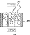
- the amount of the exhaust gas flowing through the filtration device 202 is adjusted by the extraction blower 204, but since the filtration device 202 is required to use a filtration material with sufficiently fine pores for filtering the particulate matter of a submicron-order size, the loss of pressure in the filtration device 202 is large and a large-capacity blower should be used as the extraction blower 204. In this case, after operating for a certain time, the filtration device 202 is clogged by the particulate matter 209, as shown in FIG. 18 , and the dust collection becomes impossible. The resultant unresolved problem is that the filtration device 202 should be frequently replaced.
- the particulate matter 209 is mostly collected close to the surface of the filtration device 202. In this case, the collected particulate matter 209 is exposed to the main gas flow.
- the unresolved problem encountered in this case is that when the conditions are changed to obtain a high-speed main gas flow, the particulate matter collected on the surface of the filtration device 202 is stripped away by the drag of the main gas flow, so called re-entrainment.
- the extraction blower can be omitted, and the extraction amount in the filtration device 202 is adjusted by the pressure loss regulating damper 210. Therefore, since the filtration device 202 is required to use a filtration material with sufficiently fine pores for filtering the particulate matter of a submicron-order size, the loss of pressure in the filtration device 202 is large and the pressure loss regulating damper 210 should be regulated to assume a nearly closed state. In this case, the pressure loss in the main flow caused by the pressure loss regulating damper 210 increases, and therefore a large-capacity blower should be used as the blower 205. Yet another unresolved problem is that, as shown in FIG.
- the unresolved problem encountered when the closing degree of the pressure loss regulating damper 210 is small is that, although the capacity of the blower 205 may be reduced, since the amount of gas blown through the filtration device 202 is also small, the particulate matter 209 collected on the surface of the filtration device 202 is stripped away, as shown in FIG. 19 .
- a movable mechanism such as the pressure loss regulating damper 210 is extremely prone to failure in a high-temperature exhaust gas.
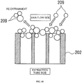
- the secondary flow created by an ion wind generated between the discharge electrode 201 and the counter electrode 207 has a maximum flow velocity of about 2 m/s. Since the filtration device 202 is required to use a filtration material with sufficiently fine pores for filtering the particulate matter of a submicron-order size and the pressure loss of the filtration device 202 is large, it is difficult to cause a sufficient amount of gas to pass through the filtration device 202 only with the secondary flow created by the ion wind, and the particulate matter 209 is mostly collected close to the surface of the filtration device 202, as shown in FIG. 20 . In this case, the collected particulate matter is exposed to the main gas flow.
- the unresolved problem encountered in this case is that when the conditions are changed to obtain a high-speed main gas flow, the particulate matter 209 collected on the surface of the filtration device 202 is stripped away by the drag of the main gas flow.
- the present invention has been created to resolve the problems unresolved in the above-described related art, and it is an objective of the present invention to provide an electrostatic precipitator that does not require a large-capacity extraction device when collecting a PM, demonstrates high dust collection performance which is free from clogging or re-entrainment under high-blowing-rate conditions, and has a low probability of failure.
- the electrostatic precipitator includes: a plate-shaped electrode having formed therein a plurality of through holes that allow a particulate matter to pass therethrough; a discharge electrode disposed to face one surface of the plate-shaped electrode; a discharge generating unit that applies a voltage between the plate-shaped electrode and the discharge electrode and generates an electric discharge imparting a Coulomb force to the particulate matter; a collection region that is formed on an opposite side of the plate-shaped electrode to a surface thereof facing the discharge electrode and collects the particulate matter; a gas flow-through region that is formed between the plate-shaped electrode and the discharge electrode and allows gas including the particulate matter to flow therethrough; and a particulate matter recovery unit that causes a recovery gas to flow through in the collection region in a direction crossing the flow-through direction of the gas including the particulate matter and strips
- the particulate matter in the gas including the particulate matter is electrically charged by the electric discharge, such as corona discharge and barrier discharge, generated between the discharge electrode and plate-shaped electrode, the charged particulate matter is moved by a Coulomb force through the through holes into the collection space formed on the surface of the plate-shaped electrode on the side opposite that facing the discharge electrode, and the particulate matter is collected in the collection space.
- the collected particulate matter is stripped away and recovered by the recovery gas flowing through in the direction crossing the flow-through direction of the exhaust gas including the particulate matter.
- the particulate matter can be reliably stripped away and recovered by the recovery gas in the flow-through state of the exhaust gas including the particulate matter, with the exhaust gas including the particulate matter not being involved in re-entrainment.
- the discharge portion of the discharge electrode is configured by thorn-shaped discharge portions. Therefore, a comparatively thick discharge portion can be formed. As a result, the processing and assembling are facilitated, the production cost can be reduced, and the service life can be extended.
- the extension direction of the plate-shaped electrode main body crosses the flow-through direction of the gas including the particulate matter.
- the PM is electrically charged and a Coulomb force is applied thereto by a barrier discharge generated between the plate-shaped electrode and the discharge electrode.
- the discharge electrode operates as a heater which is configured by a heat generating resistor connected between a pair of terminals and burns the adhered particulate matter when a voltage is applied between the pair of terminals.
- the collection region is surrounded by an angular tubular body formed by the pair of the opposing plate-shaped electrodes and a pair of end plate portions closing both end portions of the pair of plate-shaped electrodes that are parallel to the flow-through direction of the recovery gas.
- the recovery gas is sucked in from both sides of the collection region. Therefore, the recovery efficiency of the particulate matter can be increased.
- a suction hood that sucks in the recovery gas only of the collection regions is disposed between a plurality of collection regions, which are formed between the opposing electrodes, and the cyclone dust collector.
- the recovery gas can be caused by the suction hood to flow through only the collection regions, and the recovery gas can be caused to flow through in the direction crossing the direction of the exhaust gas including the particulate matter, without affecting the exhaust gas including the particulate matter. Further, since the suction location can be restricted, the flow rate of the recovery gas can be inhibited and the suction device can be reduced in size.
- a plate shaped electrode having a plurality of through holes and a discharge electrode are disposed opposite each other, a collection region is formed on a side of the plate-shaped electrode opposite that facing the discharge electrode, a PM-containing gas is caused to flow through between the plate-shaped electrode and the discharge electrode, and a voltage is applied between the plate-shaped electrode and the discharge electrode, thereby generating an electric discharge and charging the PM.
- the PM is moved by a Coulomb force through the through holes and the PM is collected in the collection space.
- the collected PM can be reliably recovered by the recovery gas flowing in the direction crossing the flow-through direction of the PM-containing gas, without re-entrainment.
- the PM collected in the collection region can be recovered without providing a large-capacity extraction blower. Furthermore, the PM is recovered without re-entrainment even under high blowing rate conditions, high dust collection performance can be demonstrated, and electrostatic precipitator with a low probability of failure can be provided.
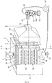
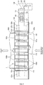
- FIG. 1 is a perspective view showing, with a partial cut-out, a housing according to the first embodiment of the present invention.
- the reference numeral 1 stands for an electrostatic precipitator that can collect particulate matter (PM) with a particle diameter equal to or less than 100 ⁇ m including, as the main component, carbon contained in exhaust gas, for example, of an internal combustion engine, in particular, a diesel engine for a ship, in particular suspended particulate matter (SPM) with a particle diameter equal to or less than 10 ⁇ m.
- PM particulate matter
- SPM suspended particulate matter
- the electrostatic precipitator 1 has, for example, a cubic housing 2.
- a plurality of dust collecting electrodes 40 each being constituted, for example, by a square plate-shaped electrode 20 and a discharge electrode 30 that faces from a predetermined distance L1, as shown in FIG. 2 , one surface of the plate-shaped electrode 20, is provided inside the housing 2.
- the plate-shaped electrode 20 is formed from a punching plate 22 in which, for example, a plurality of round through holes 21, which reach from the surface facing the discharge electrode 30, to the surface on the opposite side, is formed over the entire surface.
- the plate shape electrodes are arranged, for example, such that the plate surface thereof is in the vertical direction.
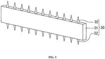
- the discharge electrode 30 has a flat rectangular cross section and includes, for example, a band-shaped electrode main body 31 extending in the horizontal direction opposite the plate-shaped electrode 20 and a large number of thorn-shaped electrode portions 32 which are formed at a predetermined distance in the horizontal direction on the upper and lower end surfaces which become the end surface sides in the cross section of the band-shaped electrode main body 31.
- the long sides in the cross section of the band-shaped electrode main body 31 are disposed parallel to each other opposite the plate-shaped electrodes 20.
- a plurality of (for example, three) discharge electrodes 30 is disposed parallel to each other at a predetermined distance in the vertical direction.
- Two dust collecting electrodes 40 are disposed at a relationship such that the plate-shaped electrodes 20 thereof face each other through a predetermined distance L2.
- the upper and lower end portions of the plate-shaped electrodes 20 disposed opposite each other are closed by end plates 23a and 23b, and an angular tubular electrode body 24 opened at the left and right ends is formed by the plate-shaped electrodes 20 and the end plates 23a and 23b.
- a high-voltage power source 45 that applies a high voltage, for example, of about 103 V to 105 V is connected between the angular tubular electrode body 24 and the discharge electrode 30, the positive electrode being connected to the angular tubular electrode body 24 and the negative electrode being connected to the discharge electrode 30.
- the positive electrode side of the high-voltage power source 45 is grounded.
- a Coulomb force acts from the electric field between the angular tubular electrode body 24 and the discharge electrodes 30 on the PM, and the PM starts moving toward the angular tubular electrode body 24. Since the PM has a certain mass, it is directly introduced by the force of inertia into the collection region 25 via the through holes 21 in the angular tubular electrode body 24.
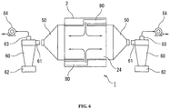
- a recovery port 61 of a cyclone dust collector 60 communicates with the suction port 51 of the separation suction hood 50.
- the cyclone dust collector 60 performs solid-gas separation of the mixed fluid including the sucked-in collected PM and recovery gas, and a blower 64 serving as a suction device is connected to a suction port 63 formed in the upper portion of a housing 60a. Where the blower 64 is actuated, gas is sucked in by the blower 64 from the suction port 63 of the cyclone dust collector 60, whereby the mixed fluid including the collected PM and recovery gas is sucked in from the recovery port 61 and subjected to solid-gas separation.
- the separated PM falls down into a PM recovery unit 62 located therebelow and is recovered.
- the separated recovery gas is returned from the upper suction port 63 through the blower 64 into the exhaust gas introducing port 3 on the lower surface side of the electric dust collecting apparatus 1.
- the exhaust gas introducing port 3 of the housing 2 in the electrostatic precipitator 1 is connected by a gas flow-through unit 71 such as a duct to a PM-containing gas discharge device 70 such as a diesel engine of a ship.
- the exhaust gas discharge port 4 of the housing 2 is likewise connected to a gas discharge unit 73 such as a chimney by a gas flow-through unit 72 such as a duct.
- the PM contained in the PM-containing gas is exposed to the corona discharge and electrically charged.
- a Coulomb force acts from the electric field between the angular tubular electrode bodies 24 and the discharge electrodes 30 upon the PM, and the PM starts moving toward the plate-shaped electrodes 20 constituting the angular tubular electrode bodies 24. Since the PM has a mass, it is caused by an inertia force to pass through the through holes 21 of the plate-shaped electrodes 20 and introduced into the internal collection regions 25.
- the external air is sucked in as the recovery gas from the openings 5 in the housing 2, and this recovery gas passes through the collection regions 25 in the direction orthogonal to the flow-through direction of the PM-containing exhaust gas. Therefore, the PM collected in the collection regions 25 is stripped away and supplied together with the recovery gas into the cyclone dust collector 60 through the separation and suction hood 50.
- the mixed fluid including the recovery gas and stripped PM which has reached the separation and suction hood 50, is introduced from the recovery port 61 into the cyclone dust collector 60, and the mixed gas is subjected to solid-gas separation.
- the separated PM falls down into the PM recovery unit 62 located in the bottom portion and recovered.
- the recovery gas including a certain amount of the separated PM is sucked in by the blower 64 from the suction port 63 and returned to the gas flow-through unit 71 close to the exhaust gas introducing port 3 of the housing 2.
- the exhaust gas may be simply caused to flow through in the gas flow channels between the discharge electrodes 30 and the plate-shaped electrodes 20 constituting the angular tubular electrode bodies 24, and it is not necessary to provide a blower as an extraction means. Further, since it is not necessary to provide a damper or the like that hinders the exhaust gas flow, the pressure loss of the exhaust gas can be reduced.
- the through holes 21 formed in the plate-shaped electrodes 20 can be formed to have a comparatively large diameter, regardless of the particle diameter of the PM, the pressure loss can be respectively suppressed. Furthermore, the PM is collected on the inner circumferential surface of the plate-shaped electrodes 20 of the angular tubular electrode bodies 24 constituting the collection regions 25. Therefore, the collection of a large amount of PM corresponding to the surface area of the plate-shaped electrodes 20 is allowed, the through holes 21 are very difficult to clog, and the collection can be reliably prevented from being hindered by clogging.
- the plate-shaped electrodes 20 can use a punching metal, the plate metal processing involving rounding or bending is unnecessary, the angular tubular electrode bodies 24 can be formed by connecting the upper and lower ends by the end plates 23a and 23b, and the processing cost can be greatly reduced.
- a plurality of band-shaped electrode main bodies 31 of the discharge electrodes 30 is disposed in parallel in the flow-through direction so as to extend in the direction crossing the flow-through direction of the PM-containing exhaust gas. Therefore, the arrangement positions of the thorn-shaped discharge portions of the discharge electrodes 30 can be shifted in the direction orthogonal to the flow-through direction of the PM-containing exhaust gas. As a result, the corona discharge can be generated everywhere over the entire region orthogonal to the flow-through direction of the PM-containing exhaust gas and the PM collection ratio of the PM-containing exhaust gas can be increased.
- discharge electrodes 30 it is not necessary to form the discharge electrodes 30 as needle-shaped electrode portions, and comparatively thick thorn-shaped electrode portions 32 may be formed. Therefore, the processing is facilitated and the service life can be extended.
- a dust collecting electrode structure can be also considered in which a discharge electrode is configured of a rod-shaped portion and a large number of needle-shaped electrode portions formed on the outer circumferential side of the rod-shaped portion, and a cylindrical electrode portion having a large number of through holes formed therein is arranged so as to surround the discharge electrode.
- a corona discharge is generated by applying a high voltage between the discharge electrode and the cylindrical electrode portion, thereby electrically charging the PM of the PM-containing exhaust gas flowing through to the inner circumferential surface side of the cylindrical electrode portion, and moving the charged PM to the collection space outside the cylindrical electrode.
- the PM collected in the collection space is blown off for recovery, for example, with an air blower in the same direction as the flow-through direction of the PM-containing exhaust gas.
- a dust collecting electrode can be formed by a simple configuration using the plate-shaped electrode 20 together with the discharge electrode 30. Further, since the flow of the recovery gas inside the collection region is formed by suction in the direction crossing the flow direction of the PM-containing exhaust gas on the outside thereof, the PM stripped away from the inner circumferential surface of the plate-shaped electrodes 20 by the recovery gas can be reliably prevented from being remixed with the PM-containing exhaust gas.
- the recovery gas suction units are provided at both ends of the collection region 25, the recovery gas suction effect is augmented and the collected PM can be stripped away and recovered with higher efficiency.
- the angular tubular electrode body 24 is formed of two plate-shaped electrodes 20 and the end plates 23a, 23b, but any tubular structure can be used, provided that the plate-shaped electrodes 20 are arranged opposite each other at the predetermined distance L2 from each other.
- the angular tubular electrode body 24 is configured by combining two dust collecting electrodes 40, but when a sufficient PM collection ratio is attained by providing only one dust collecting electrode 40, the configuration shown in FIG. 7 may be used.
- the angular tubular electrode body 24 having the collection region 25 formed inside thereof may be also configured by disposing the plate-shaped electrode 20 and the discharge electrodes 30 opposite each other at the predetermined distance L1 from each other and disposing a sealing plate 81 (can be also realized by the side wall of the housing 2) connecting the ends of the end plates 23a, 23b on the side of the plate-shaped electrode 20 opposite that where the discharge electrodes 30 are disposed.
- the separation and suction hood 50 may be disposed on the bottom surface side and the PM-containing exhaust gas may be caused to flow through in the horizontal direction.
- the discharge generated between the discharge electrodes and the plate electrodes is changed from the corona discharge to a barrier discharge.
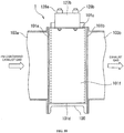
- an electrically conductive housing 100 of the electrostatic precipitator 1 is formed in a rectangular parallelepiped shape, as shown in FIGS. 9 and 10 .
- the housing 100 has a front plate portion 101a and a rear plate portion 101b, the longitudinal direction being the left-right direction.
- the housing 100 also has a top plate portion 101c and a bottom plate portion 101d connecting the upper and lower ends of the front plate portion 101a and the rear plate portion 101b, and a left plate portion 101e and a right plate portion 101f connecting the right and left ends of the front plate portion 101a and the rear plate portion 101b.
- openings 102a and 102b extending in the front-rear direction are formed, as shown in FIG. 8 , at a predetermined distance L3 in the left-right direction in the front plate portion 101a and the rear plate portion 101b.
- the width L4 of those openings 102a and 102b is set to be less than the predetermined distance L3.
- rectangular openings 102c and 102d bounded by the front plate portion 101a, rear plate portion 101b, left plate portion 101e, and right plate portion 101f are formed, as shown in FIG. 8 , in the top plate portion 101c and the bottom plate portion 101d.
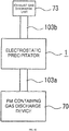
- An exhaust gas flow-through duct 103a for example, of a square cross section, which is connected to the PM-containing gas discharge device 70 such as a diesel engine for a ship, e.g. such as the above-described diesel engine for a ship, is coupled, as shown in FIG. 9 , to the opening 102a of the front plate portion 101a.
- the PM-containing gas discharge device 70 such as a diesel engine for a ship, e.g. such as the above-described diesel engine for a ship, is coupled, as shown in FIG. 9 , to the opening 102a of the front plate portion 101a.
- An exhaust gas flow-through duct 103b which is likewise of a square cross section and is connected to the above-described gas discharge unit 73, is coupled to the opening 102b of the rear plate portion 101b.
- angular tubular electrode bodies 110 having the configuration similar to that of the angular tubular electrode bodies 24 in the first embodiment are disposed in parallel between the positions excluding the openings 102a and 102b of the front plate portion 101a and the rear plate portion 101b. Therefore, the angular tubular electrode bodies 110 are disposed at a predetermined distance equal to the width L4 of the openings 102a and 102b in the direction along the exhaust gas flow-through direction and perpendicular to the exhaust gas flow-through direction.
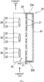
- angular tubular electrode bodies 110 are formed as rectangular parallelepipeds with open top and bottom surfaces, as shown in FIG. 8 . Further, plate-shaped electrodes 112a and 112b are disposed at the left and right side surfaces of the angular tubular electrode bodies 110 such that the distance between the outer side surfaces thereof is the abovementioned predetermined distance L3.
- Those plate-shaped electrodes 112a and 112b are each formed, for example, from a punching plate 114 in which a plurality of round through holes 113 is formed, in the same manner as the plate-shaped electrodes 20 in the above-described first embodiment, and disposed, for example, to extend in the front-rear direction, that is, in the exhaust gas flow-through direction, such that the plate surfaces thereof are in the vertical direction.
- Recovery gas intake ports 116 which directly communicate with the external air, set to have an opening ratio equal to or greater than 90% and serve to take in the recovery gas are formed, as shown in FIG. 8 , at the upper end sides of those angular tubular electrode bodies 110 and 115.
- the regions between the angular tubular electrode bodies 110 and between the angular tubular electrode bodies 110 and the angular tubular electrode bodies 115 serve as gas flow-through regions 117 through which the exhaust gas supplied from the exhaust gas flow-through duct 103a flows rearward.
- the discharge electrodes 120 are disposed to face individually the plate-shaped electrodes 112a and 112b, 112c and 112a, and 112b and 112c.
- the discharge electrode 120 is formed in a rectangular shape along the exhaust gas flow-through direction. As shown in FIG. 11 , the discharge electrode 120 has the configuration of a ceramic heater having a heat-generating resistor 122 formed in a zigzag manner on a flat surface incorporated in an alumina or silicon nitride ceramic 121 which is a dielectric. In the heat-generating resistor 122, terminal connection pads 123a and 123b are formed at both ends at the front and rear positions in the upper portion thereof. Lead terminals 124a and 124b extending to the outside are joined by soldering or the like to the terminal connection pads 123a and 123b. In other words, the discharge electrode 120 has a configuration in which the heat-generating resistor 122 is covered by the ceramic 121 as a dielectric.
- each discharge electrode 120 is supported by a heat-resistant insulating spacer 125 disposed on the opening 102c side of the top plate portion 101c of the housing 2 and a heat-resistant insulating spacer 126 disposed between the lower ends of the angular tubular electrode body 110, between the lower ends of the angular tubular electrode bodies 115 and 110 and between the lower ends of the angular tubular electrode body 110 and the angular tubular electrode body 115.
- a barrier discharge generating unit 130 serving as a discharge generating unit is connected to the high-voltage power supply bars 128a and 128b.
- the barrier discharge generating unit 130 has a high-withstand-voltage power relay 131, which is connected between the high-voltage power supply bars 128a and 128b, and a serial circuit of a high-withstand-voltage power relay 132, which is connected between the ground and a connection point of one terminal of the high-withstand-voltage power relay 131 and the high-voltage power supply bar 128a, and high-voltage AC power source 133 generating a high-voltage AC, for example, of 10 kV.
- a point between the high-voltage AC power source 133 and the ground is connected to the housing 100.
- the biased state of the high-withstand-voltage power relays 131 and 132 is periodically canceled, the application of a high-voltage AC to the discharge electrodes 120 is stopped, the high-withstand-voltage power relays 136 and 137 are instead set to the biased state, and a low-voltage AC is applied to the lead terminals 124a and 124b of the discharge electrodes 120, thereby actuating the discharge electrodes 120 as ceramic heaters.
- the discharge electrodes 120 are heated to about 800°C for about 1 min to 2 min, and the entire PM adhered to the surface is burned and removed.
- the exhaust gas flow-through duct 103a coupled to the housing 100 in the electrostatic precipitator 1 is connected to a PM-containing gas discharge device 70 such as a diesel engine of a ship.
- the exhaust gas flow-through duct 103b coupled to the housing 100 is connected to a gas discharge unit 73 such as a chimney.
- a barrier discharge plasma column is generated and a barrier discharge is generated between the discharge electrodes 120 and the plate-shaped electrodes 112a to 112c of the angular tubular electrode bodies 110 and 115. Since the heat-generating resistor 122 serving as an electrode in the discharge electrode 120 is covered with the ceramic 121, which is a dielectric, the barrier discharge is a silent discharge causing no sparks.
- the PM-containing exhaust gas is caused to flow between the discharge electrodes 120 and the plate-shaped electrodes 112a to 112c.
- the PM contained in the PM-containing exhaust gas is electrically charged when passing through the barrier discharge plasma column, a Coulomb force acts thereupon from the electric field produced by the barrier discharge maintaining voltage, and the PM moves toward the plate-shaped electrodes 112a to 112c serving as ground electrodes.
- the plate-shaped electrodes 112a to 112c serving as ground electrodes.
- not all the PM acted upon by the Coulomb force moves toward the plate-shaped electrodes 112a to 112c and some PM moves toward the discharge electrode 120.
- the PM moving toward the plate-shaped electrodes 112a to 112c is introduced to the collection regions inside the angular tubular electrode bodies 110 and 115 from the through holes 111 formed in the plate-shaped electrodes 112a to 112c, in the same manner as in the above-described first embodiment.
- the mixed fluid including the recovery gas and stripped PM which has reached the suction hood 140, is introduced from the suction port 141 into the cyclone dust collector 60, and the mixed gas is subjected to solid-gas separation.
- the separated PM falls down into the PM recovery unit 62 located in the bottom portion and recovered.
- the recovery gas including a certain amount of the separated PM is sucked in by the blower 64 from the suction port 63 and returned to the vicinity of the opening 102a of the exhaust gas flow-through duct 103a coupled to the housing 100.
- a barrier discharge plasma column is formed between the discharge electrodes 120 and the plate-shaped electrodes 112a to 112c, and a barrier discharge is generated. Since the heat-generating resistor 122 which serves as an electrode of the discharge electrode 120 in this process is covered with the ceramic 121, the discharge current flows through the ceramic 121 from the heat-generating resistor 122, and a silent discharge causing no sparks is generated till the insulation breakdown of the ceramic 121 itself is reached.
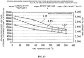
- the discharge characteristic is such as shown in FIG. 13 .
- the spark discharge voltage is represented by a characteristic line L11
- the corona discharge start voltage is represented by a characteristic line L12
- the gas density ratio is represented by a characteristic line L13.
- the spark discharge voltage does not decrease significantly when the PM-containing exhaust gas temperature is equal to or lower than 150°C, but where the temperature exceeds 150°C, the decrease ratio of the spark discharge voltage related to the increase in exhaust gas temperature increases.
- the flow-through direction of the recovery gas which recovers the collected PM
- the flow-through direction of the recovery gas is orthogonal to the flow-through direction of the PM-containing exhaust gas, but such a configuration is not limiting and the PM-containing exhaust gas and the recovery gas may be caused to flow in the directions crossing each other.
- blower 64 is used as the suction device, but such a configuration is not limiting, and another suction device such as a vacuum ejector can be used.
- an electrostatic precipitator that does not require a large-capacity extraction device, demonstrates high dust collection performance which is free from clogging or re-entrainment under high-blowing-rate conditions, and has a low probability of failure.
- 1 -electrostatic precipitator 2 - housing; 3 - gas introducing port; 4 - gas discharge port; 5 - opening; 20 - plate-shaped electrode; 21 - through hole; 22 - punching metal; 23a, 23b - end plates; 24 - angular tubular electrode body; 30 - discharge electrode; 31 - band-shaped electrode main body; 32 - thorn-shaped electrode portion; 33 - gas flow-through region; 40 - dust collecting electrode; 50 - separation and suction hood; 60 - cyclone dust collector; 62 - PM recovery unit; 64 - blower; 100 - housing; 103a, 103b - exhaust gas flow-through ducts; 110, 115 - angular tubular bodies; 112a to 112c - plate-shaped electrodes; 117 - gas flow-through region; 120 - discharge electrode; 121 - ceramics; 122 - heat-generating resistor; 124a, 124b - lead terminals; 128a
Landscapes
- Electrostatic Separation (AREA)
- Processes For Solid Components From Exhaust (AREA)
Description
- The present invention relates to an electrostatic precipitator that removes particulate matter (PM) from a PM-containing gas such as exhaust gas, for example, of an internal combustion engine, which includes the PM.
- Exhaust gas discharged from an internal combustion engine includes hazardous substances such as NOx, SOx, and also PM including carbon as the main component. The PM that has penetrated into a human body as a result of breathing is known to cause various health problems, and it is desirable to develop a PM collecting apparatus with high collection efficiency.
- A method in which a filter is disposed in an exhaust gas duct can be used in such a PM removing apparatus, but the filter can be easily clogged and has a large pressure loss. By contrast, an electrostatic precipitator does not have a risk of clogging and has a small pressure loss, and therefore can be effectively installed in the exhaust gas duct of an internal combustion engine.
- A dust collecting apparatus comprising a
discharge electrode 201 in a flow of gas including a particulate matter, afiltration device 202 provided opposite thedischarge electrode 201, a high-voltage power source 203 that applies a high voltage between thedischarge electrode 201 and thefiltration device 202, anextraction blower 204 that adjusts the gas flow passing through thefiltration device 202, and amain blower 205 that sucks in the exhaust gas, for example, as shown inFIG. 14 , is known as a PM collecting apparatus of such an electric dust collection system (see, for example, Patent Document 1). Likewise, a dust collecting apparatus is also known in which theextraction blower 204 is omitted, a gas outlet is divided in two, and adamper 210 for pressure loss adjustment is provided in each gas outlet instead of the blower, as shown inFIG. 15 (see, for example, Patent Document 1). - A dust removing apparatus is also known which includes a
discharge electrode 201 in a gas flow including a particulate matter, afiltration device 202 having acounter electrode 207 disposed opposite thedischarge electrode 201, a high-voltage power source 203 that applies a high voltage between thedischarge electrode 201 and thefiltration device 202, and a closedspace 208 provided inside the filtration means 202 or at the rear surface thereof, as shown inFIGS. 16 and17 (see, for example, Patent Document 2). -
- Patent Document 1: Japanese Patent Application Publication No.
H2-63560 - Patent Document 2: Japanese Patent Application Publication No.
H2-184357 -
JP 2007 100635 A -
JP 2011 245429 A discharge electrode 2 arranged on a central part of the tubular electrode, wherein a voltage is applied between the tubular electrode 3 and thedischarge electrode 2 while causing a gas containing particulate material to flow through an inner part of the tubular electrode 3, a corona discharge is generated and, thereby, the particulate material 5 in the gas containing the particulate material is removed. A large number of through-holes 3b for causing the particulate material to pass therethrough are formed in the tubular electrode 3, at the same time, the tubular electrode 3 is arranged in atubular casing electrode 4 larger than the tubular electrode 3 and a potential having the same polarity as the tubular electrode 3 is applied to thecasing electrode 4. - However, in the conventional example shown in
FIG. 14 which is described inPatent Document 1, the amount of the exhaust gas flowing through thefiltration device 202 is adjusted by theextraction blower 204, but since thefiltration device 202 is required to use a filtration material with sufficiently fine pores for filtering the particulate matter of a submicron-order size, the loss of pressure in thefiltration device 202 is large and a large-capacity blower should be used as theextraction blower 204. In this case, after operating for a certain time, thefiltration device 202 is clogged by theparticulate matter 209, as shown inFIG. 18 , and the dust collection becomes impossible. The resultant unresolved problem is that thefiltration device 202 should be frequently replaced. Conversely, where the capacity of theextraction blower 204 is small, the amount of gas flowing through thefiltration device 202 is small. Therefore, as shown inFIG. 19 , theparticulate matter 209 is mostly collected close to the surface of thefiltration device 202. In this case, the collectedparticulate matter 209 is exposed to the main gas flow. The unresolved problem encountered in this case is that when the conditions are changed to obtain a high-speed main gas flow, the particulate matter collected on the surface of thefiltration device 202 is stripped away by the drag of the main gas flow, so called re-entrainment. - Likewise, in the conventional example shown in
FIG. 15 and described inPatent Document 1, the extraction blower can be omitted, and the extraction amount in thefiltration device 202 is adjusted by the pressureloss regulating damper 210. Therefore, since thefiltration device 202 is required to use a filtration material with sufficiently fine pores for filtering the particulate matter of a submicron-order size, the loss of pressure in thefiltration device 202 is large and the pressureloss regulating damper 210 should be regulated to assume a nearly closed state. In this case, the pressure loss in the main flow caused by the pressureloss regulating damper 210 increases, and therefore a large-capacity blower should be used as theblower 205. Yet another unresolved problem is that, as shown inFIG. 18 , where thefiltration device 202 operates for a certain time, the device is clogged and the dust collection becomes impossible. Conversely, the unresolved problem encountered when the closing degree of the pressureloss regulating damper 210 is small is that, although the capacity of theblower 205 may be reduced, since the amount of gas blown through thefiltration device 202 is also small, theparticulate matter 209 collected on the surface of thefiltration device 202 is stripped away, as shown inFIG. 19 . Yet another unresolved problem is that a movable mechanism such as the pressureloss regulating damper 210 is extremely prone to failure in a high-temperature exhaust gas. - In the conventional example shown in
FIG. 16 and described inPatent Document 2, the secondary flow created by an ion wind generated between thedischarge electrode 201 and thecounter electrode 207 has a maximum flow velocity of about 2 m/s. Since thefiltration device 202 is required to use a filtration material with sufficiently fine pores for filtering the particulate matter of a submicron-order size and the pressure loss of thefiltration device 202 is large, it is difficult to cause a sufficient amount of gas to pass through thefiltration device 202 only with the secondary flow created by the ion wind, and theparticulate matter 209 is mostly collected close to the surface of thefiltration device 202, as shown inFIG. 20 . In this case, the collected particulate matter is exposed to the main gas flow. The unresolved problem encountered in this case is that when the conditions are changed to obtain a high-speed main gas flow, theparticulate matter 209 collected on the surface of thefiltration device 202 is stripped away by the drag of the main gas flow. - The present invention has been created to resolve the problems unresolved in the above-described related art, and it is an objective of the present invention to provide an electrostatic precipitator that does not require a large-capacity extraction device when collecting a PM, demonstrates high dust collection performance which is free from clogging or re-entrainment under high-blowing-rate conditions, and has a low probability of failure.
- In order to attain the abovementioned objective, the present invention provides an electrostatic precipitator according to
claim 1. Preferred embodiments are described independent claims 2 to 13. According to a first aspect of the present invention, the electrostatic precipitator includes: a plate-shaped electrode having formed therein a plurality of through holes that allow a particulate matter to pass therethrough; a discharge electrode disposed to face one surface of the plate-shaped electrode; a discharge generating unit that applies a voltage between the plate-shaped electrode and the discharge electrode and generates an electric discharge imparting a Coulomb force to the particulate matter; a collection region that is formed on an opposite side of the plate-shaped electrode to a surface thereof facing the discharge electrode and collects the particulate matter; a gas flow-through region that is formed between the plate-shaped electrode and the discharge electrode and allows gas including the particulate matter to flow therethrough; and a particulate matter recovery unit that causes a recovery gas to flow through in the collection region in a direction crossing the flow-through direction of the gas including the particulate matter and strips and recovers the collected particulate matter in a flow-through state of the gas including the particulate matter. The particulate matter in the gas including particulate matter is electrically charged by the electric discharge and collected in the collection region through the through holes, and the particulate matter collected in the collection region is stripped away and recovered by the recovery gas. - With such a configuration, the particulate matter in the gas including the particulate matter is electrically charged by the electric discharge, such as corona discharge and barrier discharge, generated between the discharge electrode and plate-shaped electrode, the charged particulate matter is moved by a Coulomb force through the through holes into the collection space formed on the surface of the plate-shaped electrode on the side opposite that facing the discharge electrode, and the particulate matter is collected in the collection space. The collected particulate matter is stripped away and recovered by the recovery gas flowing through in the direction crossing the flow-through direction of the exhaust gas including the particulate matter. As a result, the particulate matter can be reliably stripped away and recovered by the recovery gas in the flow-through state of the exhaust gas including the particulate matter, with the exhaust gas including the particulate matter not being involved in re-entrainment.
- In the electrostatic precipitator according to a second aspect of the present invention, the discharge generating unit generates a corona discharge by applying a DC voltage between the plate-shaped electrode and the discharge electrode.
- According to the second aspect, the PM is electrically charged and a Coulomb force is applied thereto by a corona discharge generated between the plate-shaped electrode and the discharge electrode.
- In the electrostatic precipitator according to a third aspect of the present invention, the discharge electrode includes: a plate-shaped electrode main body that has a rectangular cross section, with the long sides of the cross section facing the plate-shaped electrode; and thorn-shaped discharge portions formed at the short sides of the cross section of the plate-shaped electrode main body.
- According to the third aspect, the discharge portion of the discharge electrode is configured by thorn-shaped discharge portions. Therefore, a comparatively thick discharge portion can be formed. As a result, the processing and assembling are facilitated, the production cost can be reduced, and the service life can be extended.
- In the electrostatic precipitator according to a fourth aspect of the present invention, the extension direction of the plate-shaped electrode main body crosses the flow-through direction of the gas including the particulate matter.
- According to the fourth aspect, with such a configuration, by arranging the thorn-shaped discharge portion in a plurality of discharge electrodes such that positions thereof do not overlap, it is possible to form the corona discharge region effective with respect to the entire gas including the particulate matter that flows therethrough and the particulate matter removal ratio can be increased.
- In the electrostatic precipitator according to a fifth aspect of the present invention, the discharge generating unit generates a barrier discharge by applying an AC voltage between the plate-shaped electrode and the discharge electrode.
- According to the fifth aspect, the PM is electrically charged and a Coulomb force is applied thereto by a barrier discharge generated between the plate-shaped electrode and the discharge electrode.
- In the electrostatic precipitator according to a sixth aspect of the present invention, the discharge electrode is formed by a metal electrode and a dielectric covering the metal electrode to have a plate shape having a plate surface along the flow-through direction of the gas including the particulate matter.
- According to the sixth aspect, since the metal electrode is covered by the dielectric, a barrier discharge plasma column can be generated between the discharge electrode and the opposing plate-shaped electrode and a silent discharge can be realized.
- In the electrostatic precipitator according to a seventh aspect of the present invention, the discharge electrode operates as a heater which is configured by a heat generating resistor connected between a pair of terminals and burns the adhered particulate matter when a voltage is applied between the pair of terminals.
- According to the seventh aspect, the particulate matter adhered to the discharge electrode can be burned and removed.
- In the electrostatic precipitator according to an eighth aspect of the present invention, two sets of the plate-shaped electrode and the discharge electrodes are disposed in parallel in a relationship such that the plate-shaped electrodes face each other, and the collection region is formed between the opposing plate-shaped electrodes.
- According to the eighth aspect, two sets of the plate-shaped electrode and the discharge electrodes are combined to form the collection space between the plate-shaped electrodes. Therefore, the width can be reduced by comparison with the case in which the collection spaces are provided individually.
- In the electrostatic precipitator according to a ninth aspect of the present invention, the collection region is surrounded by an angular tubular body formed by the pair of the opposing plate-shaped electrodes and a pair of end plate portions closing both end portions of the pair of plate-shaped electrodes that are parallel to the flow-through direction of the recovery gas.
- According to the ninth aspect, the collection region is surrounded by an angular tubular body, and the recovery gas flows through inside thereof. As a result, the recovery gas can be caused to flow through without affecting the flow-through state of the gas including the particulate matter.
- In the electrostatic precipitator according to a tenth aspect of the present invention, a cyclone dust collector is connected to one side of the collection region in a recovery gas flow-through direction, a suction device is connected to the cyclone dust collector, and a recovery gas flow is formed by a suction force of the suction device.
- According to the tenth aspect, since the recovery gas flow is formed by suction, the particulate matter can be reliably recovered without being involved in re-entrainment.
- In the electrostatic precipitator according to an eleventh aspect of the present invention, cyclone dust collectors are individually connected to both sides of the collection region in a recovery gas flow-through direction, a suction device is connected to each of the cyclone dust collectors, and a bidirectional recovery gas flow is formed by a suction force of the suction device.
- According to the eleventh aspect, the recovery gas is sucked in from both sides of the collection region. Therefore, the recovery efficiency of the particulate matter can be increased.
- In the electrostatic precipitator according to a twelfth aspect of the present invention, a suction hood that sucks in the recovery gas only of the collection regions is disposed between a plurality of collection regions, which are formed between the opposing electrodes, and the cyclone dust collector.
- With such a configuration, the recovery gas can be caused by the suction hood to flow through only the collection regions, and the recovery gas can be caused to flow through in the direction crossing the direction of the exhaust gas including the particulate matter, without affecting the exhaust gas including the particulate matter. Further, since the suction location can be restricted, the flow rate of the recovery gas can be inhibited and the suction device can be reduced in size.
- In accordance with the present invention, a plate shaped electrode having a plurality of through holes and a discharge electrode are disposed opposite each other, a collection region is formed on a side of the plate-shaped electrode opposite that facing the discharge electrode, a PM-containing gas is caused to flow through between the plate-shaped electrode and the discharge electrode, and a voltage is applied between the plate-shaped electrode and the discharge electrode, thereby generating an electric discharge and charging the PM. As a result, the PM is moved by a Coulomb force through the through holes and the PM is collected in the collection space. The collected PM can be reliably recovered by the recovery gas flowing in the direction crossing the flow-through direction of the PM-containing gas, without re-entrainment. The PM collected in the collection region can be recovered without providing a large-capacity extraction blower. Furthermore, the PM is recovered without re-entrainment even under high blowing rate conditions, high dust collection performance can be demonstrated, and electrostatic precipitator with a low probability of failure can be provided.
-
-
FIG. 1 is a perspective view, with a partial cut-out, of a housing showing the first embodiment of the electrostatic precipitator in accordance with the present invention; -
FIG. 2 is a cross-sectional view taken along the A-A line inFIG. 1 ; -
FIG. 3 is a perspective view of a discharge electrode that can be used in the present invention; -
FIG. 4 is a cross-sectional view of a separation and suction hood taken along the B-B line inFIG. 1 ; -
FIG. 5 is a schematic diagram showing the schematic configuration of the exhaust gas treatment system; -
FIG. 6 is a schematic configuration diagram showing another embodiment of the present invention; -
FIG. 7 is a cross-sectional view of the principal portion illustrating yet another embodiment of the present invention; -
FIG. 8 is a vertical sectional view illustrating the second embodiment of the present invention; -
FIG. 9 is a cross-sectional view taken along the C-C line inFIG. 8 ; -
FIG. 10 is a side view of the configuration shown inFIG. 8 ; -
FIG. 11 shows the discharge electrode that can be used in the second embodiment, withFIG. 11(a) being a perspective view of the entire configuration andFIG. 11(b) being a perspective view of a state with a separated dielectric plate; -
FIG. 12 is a schematic diagram showing the schematic configuration of the exhaust gas treatment system using the second embodiment; -
FIG. 13 is a characteristic diagram showing a corona discharge characteristic; -
FIG. 14 is an explanatory drawing illustrating an example of the related art; -
FIG. 15 is an explanatory drawing illustrating another example of the related art; -
FIG. 16 is an explanatory drawing illustrating yet another example of the related art; -
FIG. 17 is a detailed configuration diagram of the filtration device shown inFIG. 14 ; -
FIG. 18 is a schematic diagram showing a particulate matter collection state in the filtration device; -
FIG. 19 is a schematic diagram showing a re-entrainment state in the filtration device; and -
FIG. 20 is a schematic diagram showing a re-entrainment state in the filtration device. - The embodiments of the present invention will be explained hereinbelow with reference to the appended drawings.
-
FIG. 1 is a perspective view showing, with a partial cut-out, a housing according to the first embodiment of the present invention. - In the figure, the
reference numeral 1 stands for an electrostatic precipitator that can collect particulate matter (PM) with a particle diameter equal to or less than 100 µm including, as the main component, carbon contained in exhaust gas, for example, of an internal combustion engine, in particular, a diesel engine for a ship, in particular suspended particulate matter (SPM) with a particle diameter equal to or less than 10 µm. - The
electrostatic precipitator 1 has, for example, acubic housing 2. A plurality ofdust collecting electrodes 40, each being constituted, for example, by a square plate-shapedelectrode 20 and adischarge electrode 30 that faces from a predetermined distance L1, as shown inFIG. 2 , one surface of the plate-shapedelectrode 20, is provided inside thehousing 2. - The plate-shaped
electrode 20 is formed from a punchingplate 22 in which, for example, a plurality of round throughholes 21, which reach from the surface facing thedischarge electrode 30, to the surface on the opposite side, is formed over the entire surface. The plate shape electrodes are arranged, for example, such that the plate surface thereof is in the vertical direction. - Further, as shown in
FIG. 3 , thedischarge electrode 30 has a flat rectangular cross section and includes, for example, a band-shaped electrodemain body 31 extending in the horizontal direction opposite the plate-shapedelectrode 20 and a large number of thorn-shapedelectrode portions 32 which are formed at a predetermined distance in the horizontal direction on the upper and lower end surfaces which become the end surface sides in the cross section of the band-shaped electrodemain body 31. The long sides in the cross section of the band-shaped electrodemain body 31 are disposed parallel to each other opposite the plate-shapedelectrodes 20. - In the present configuration, a plurality of (for example, three)
discharge electrodes 30 is disposed parallel to each other at a predetermined distance in the vertical direction. - Two
dust collecting electrodes 40 are disposed at a relationship such that the plate-shapedelectrodes 20 thereof face each other through a predetermined distance L2. The upper and lower end portions of the plate-shapedelectrodes 20 disposed opposite each other are closed byend plates tubular electrode body 24 opened at the left and right ends is formed by the plate-shapedelectrodes 20 and theend plates - Therefore, the interior of the angular
tubular electrode body 24 serves as aPM collection region 25, and a plurality ofdischarge electrodes 30 is disposed at positions facing the plate-shapedelectrodes 20 on the outside of the angulartubular electrode body 24. - Therefore, in the adjacent
dust collecting electrodes 40, thedischarge electrode 30 is shared, and thedischarge electrode 30, angulartubular electrode body 24,discharge electrode 30, and angulartubular electrode body 24 are disposed in parallel in the order of description. The number of thedischarge electrodes 30 and angulartubular electrode bodies 24 is set according to the flow rate of the PM-containing exhaust gas from which the particulate matter should be collected. - Further, a high-
voltage power source 45 that applies a high voltage, for example, of about 103 V to 105 V is connected between the angulartubular electrode body 24 and thedischarge electrode 30, the positive electrode being connected to the angulartubular electrode body 24 and the negative electrode being connected to thedischarge electrode 30. The positive electrode side of the high-voltage power source 45 is grounded. - Therefore, a corona discharge is generated between the angular
tubular electrode body 24 and the thorn-shapedelectrode portions 32 of thedischarge electrodes 30, and the PM of the PM-containing exhaust gas passing through a gas flow-throughregion 33 formed between the angulartubular electrode body 24 and thedischarge electrodes 30 is exposed to the corona discharge and electrically charged. - Further, a Coulomb force acts from the electric field between the angular
tubular electrode body 24 and thedischarge electrodes 30 on the PM, and the PM starts moving toward the angulartubular electrode body 24. Since the PM has a certain mass, it is directly introduced by the force of inertia into thecollection region 25 via the throughholes 21 in the angulartubular electrode body 24. - In the
collection region 25, since the flow field is extremely weak, the PM is hardly affected by the flow field, and the PM receives an electric image force created by the difference in electric potential between the electric charges carried by the PM itself and the plate-shapedelectrode 20 of the angulartubular electrode body 24 and is collected by moving to the inner circumferential surface of the plate-shapedelectrode 20, which constitutes the angulartubular electrode body 24, and adhering thereto. - Further, an exhaust gas introducing port 3 and an exhaust
gas discharge port 4 through which the PM-containing exhaust gas passes are formed in the lower surface and upper surface of thehousing 2, respectively, and the PM-containing gas introduced into thehousing 2 from the exhaust gas introducing port 3 flows through vertically in the direction crossing the extension direction of thedischarge electrodes 30 between thedischarge electrodes 30 and the plate-shapedelectrodes 20 of the angulartubular electrode bodies 24, and then the PM-containing gas is discharged from the exhaustgas discharge port 4. - A plurality of openings 5 facing the inner surface of the angular
tubular electrode bodies 24 is formed, for example, in the left end surface of thehousing 2, and a separation andsuction hood 50 serving as a PM recovery unit that sucks in the recovery gas only from the inner surface side of the angulartubular electrode bodies 24 is disposed at the right end surface. As shown inFIG. 4 , the separation andsuction hood 50 hasseparation suction passages 52 communicating with the inner surface of the angulartubular electrode bodies 24 and communicating with asuction port 51 at the other end. In order to facilitate the understanding of the explanation of the example, inFIG. 1 , the right end surfaces of thehousing 2 and the angulartubular electrode bodies 24 are shown as separated from the separation andsuction hood 50. However, in the actual configuration of the example, as shown inFIG. 4 , the right end surfaces of thehousing 2 and the angulartubular electrode bodies 24 are not separated from the separation andsuction hood 50. The separation andsuction hood 50 is disposed in contact with the right end surfaces of thehousing 2 and the angulartubular electrode bodies 24. - A
recovery port 61 of acyclone dust collector 60 communicates with thesuction port 51 of theseparation suction hood 50. Thecyclone dust collector 60 performs solid-gas separation of the mixed fluid including the sucked-in collected PM and recovery gas, and ablower 64 serving as a suction device is connected to asuction port 63 formed in the upper portion of a housing 60a. Where theblower 64 is actuated, gas is sucked in by theblower 64 from thesuction port 63 of thecyclone dust collector 60, whereby the mixed fluid including the collected PM and recovery gas is sucked in from therecovery port 61 and subjected to solid-gas separation. The separated PM falls down into aPM recovery unit 62 located therebelow and is recovered. The separated recovery gas is returned from theupper suction port 63 through theblower 64 into the exhaust gas introducing port 3 on the lower surface side of the electricdust collecting apparatus 1. - Further, since the
cyclone dust collector 60 is connected to thecollection regions 25 inside the angulartubular electrode bodies 24 through theseparation suction hood 50, where theblower 64 is actuated, the external air is sucked in as the recovery gas from the openings 5 in thehousing 2, and this recovery gas passes through thecollection regions 25 in the direction orthogonal to the flow direction of the PM-containing exhaust gas. As a result, the PM collected in thecollection regions 25 is stripped away and supplied together with the recovery gas into thecyclone dust collector 60 through theseparation suction hood 50. - The operation of the first embodiment is explained below.
- First, as shown schematically in
FIG. 5 , the exhaust gas introducing port 3 of thehousing 2 in theelectrostatic precipitator 1 is connected by a gas flow-throughunit 71 such as a duct to a PM-containinggas discharge device 70 such as a diesel engine of a ship. The exhaustgas discharge port 4 of thehousing 2 is likewise connected to agas discharge unit 73 such as a chimney by a gas flow-throughunit 72 such as a duct. - Where the PM-containing
gas discharge device 70 is actuated in this state, the PM-containing exhaust gas is outputted from the PM-containinggas discharge device 70, and this PM-containing exhaust gas is introduced into the exhaust gas introducing port 3 in thehousing 2 of theelectrostatic precipitator 1. - As a result of applying a high voltage from the high-
voltage power source 45 between the angulartubular electrode bodies 24 and thedischarge electrodes 30, a corona discharge crossing the gas flow-throughregions 33 of the PM-containing gas is generated from the tips of the thorn-shapedelectrode portions 32 of thedischarge electrodes 30 toward thedischarge electrodes 30 constituting the angulartubular electrode bodies 24. - Therefore, the PM contained in the PM-containing gas is exposed to the corona discharge and electrically charged. A Coulomb force acts from the electric field between the angular
tubular electrode bodies 24 and thedischarge electrodes 30 upon the PM, and the PM starts moving toward the plate-shapedelectrodes 20 constituting the angulartubular electrode bodies 24. Since the PM has a mass, it is caused by an inertia force to pass through the throughholes 21 of the plate-shapedelectrodes 20 and introduced into theinternal collection regions 25. - In the
collection regions 25, since the flow field is extremely weak, the PM is hardly affected by the flow field, and the PM receives an electric image force created by the difference in electric potential between the electric charges carried by the PM itself and the plate-shapedelectrodes 20 of the angulartubular electrode bodies 24 and is collected by moving to the inner circumferential surface of the plate-shapedelectrodes 20 and adhering thereto. - Where the PM is thus collected on the inner circumferential surface of the plate-shaped
electrodes 20 and theblower 64 is actuated with a predetermined period, the external air is sucked in as the recovery gas from the openings 5 in thehousing 2, and this recovery gas passes through thecollection regions 25 in the direction orthogonal to the flow-through direction of the PM-containing exhaust gas. Therefore, the PM collected in thecollection regions 25 is stripped away and supplied together with the recovery gas into thecyclone dust collector 60 through the separation andsuction hood 50. In this case, by setting the opening ratio of the throughholes 21 of the plate-shapedelectrodes 20 to 20% to 40% and setting the opening ratio of the openings 5 to 90% or greater, it is possible to increase the flow channel resistance in the throughholes 21 of the plate-shapedelectrodes 20 and minimize the suction of the PM-containing exhaust gas by the recovery gas. As a result, even when the flow velocity of the recovery gas is increased, the PM-containing exhaust gas is not sucked in and the PM collected on the inner circumferential surface of the plate-shapedelectrodes 20 can be efficiently stripped away and discharged to the separation andsuction hood 50. - In this case, in the separation and
suction hood 50, recovery gas suction passages (separation and suction passages 52) are formed at positions facing the inner circumferential surface of the angulartubular electrode bodies 24. Therefore, since the recovery gas suction passages are not open in the PM-containing exhaust gas flow channels in the angulartubular electrode bodies 24, the PM-containing gas can be reliably prevented from being directly sucked in. - Further, the mixed fluid including the recovery gas and stripped PM, which has reached the separation and
suction hood 50, is introduced from therecovery port 61 into thecyclone dust collector 60, and the mixed gas is subjected to solid-gas separation. The separated PM falls down into thePM recovery unit 62 located in the bottom portion and recovered. The recovery gas including a certain amount of the separated PM is sucked in by theblower 64 from thesuction port 63 and returned to the gas flow-throughunit 71 close to the exhaust gas introducing port 3 of thehousing 2. - Thus, with the first embodiment, since the PM is collected in the
collection regions 25 formed opposite the PM-containing exhaust gas flow channel, with the plate-shaped electrodes being interposed therebetween, by causing the recovery gas to flow in the direction crossing the flow-through direction of the PM-containing exhaust gas in thecollection regions 25 in the flow-through state of the PM-containing exhaust gas, it is possible to strip away and reliably recover the collected PM, without remixing the collected PM with the PM-containing exhaust gas. - In this case, the exhaust gas may be simply caused to flow through in the gas flow channels between the
discharge electrodes 30 and the plate-shapedelectrodes 20 constituting the angulartubular electrode bodies 24, and it is not necessary to provide a blower as an extraction means. Further, since it is not necessary to provide a damper or the like that hinders the exhaust gas flow, the pressure loss of the exhaust gas can be reduced. - In addition, since the through
holes 21 formed in the plate-shapedelectrodes 20 can be formed to have a comparatively large diameter, regardless of the particle diameter of the PM, the pressure loss can be respectively suppressed. Furthermore, the PM is collected on the inner circumferential surface of the plate-shapedelectrodes 20 of the angulartubular electrode bodies 24 constituting thecollection regions 25. Therefore, the collection of a large amount of PM corresponding to the surface area of the plate-shapedelectrodes 20 is allowed, the throughholes 21 are very difficult to clog, and the collection can be reliably prevented from being hindered by clogging. - Further, since the flow strength of the flow field in the
collection region 25 is weak, the collected PM is unlikely to be scattered again into the exhaust gas flow channel. Yet another attainable effect is that since no movable parts, such as a damper or a blower, is present in theelectrostatic precipitator 1, the possibility of a malfunction is extremely low. - Further, the plate-shaped
electrodes 20 can use a punching metal, the plate metal processing involving rounding or bending is unnecessary, the angulartubular electrode bodies 24 can be formed by connecting the upper and lower ends by theend plates - Further, the sets of the
discharge electrodes 30 and the plate-shapedelectrodes 20 are combined so that the plate-shaped electrodes of the two sets face each other and thecollection regions 25 are formed between the plate-shapedelectrodes 20. Therefore, because only one collection space is used, the spacing in the width direction can be reduced and the configuration can be narrowed by comparison with that in which the collection region is provided in each set of thedischarge electrode 30 and the plate-shapedelectrode 20. - Further, a plurality of band-shaped electrode
main bodies 31 of thedischarge electrodes 30 is disposed in parallel in the flow-through direction so as to extend in the direction crossing the flow-through direction of the PM-containing exhaust gas. Therefore, the arrangement positions of the thorn-shaped discharge portions of thedischarge electrodes 30 can be shifted in the direction orthogonal to the flow-through direction of the PM-containing exhaust gas. As a result, the corona discharge can be generated everywhere over the entire region orthogonal to the flow-through direction of the PM-containing exhaust gas and the PM collection ratio of the PM-containing exhaust gas can be increased. - Further, it is not necessary to form the
discharge electrodes 30 as needle-shaped electrode portions, and comparatively thick thorn-shapedelectrode portions 32 may be formed. Therefore, the processing is facilitated and the service life can be extended. - A dust collecting electrode structure can be also considered in which a discharge electrode is configured of a rod-shaped portion and a large number of needle-shaped electrode portions formed on the outer circumferential side of the rod-shaped portion, and a cylindrical electrode portion having a large number of through holes formed therein is arranged so as to surround the discharge electrode. In this case, a corona discharge is generated by applying a high voltage between the discharge electrode and the cylindrical electrode portion, thereby electrically charging the PM of the PM-containing exhaust gas flowing through to the inner circumferential surface side of the cylindrical electrode portion, and moving the charged PM to the collection space outside the cylindrical electrode. The PM collected in the collection space is blown off for recovery, for example, with an air blower in the same direction as the flow-through direction of the PM-containing exhaust gas.
- With such a configuration, the PM collected in the collection space is blown off by the air blower, and most of the blown PM is not sucked from the suction port facing the air blower. For this reason, the PM can be remixed with the PM-containing exhaust gas flowing inside the cylindrical electrode and can be released to the atmosphere. Thus, the recovery efficiency of the collected PM can decrease. Further, the processing cost of the cylindrical electrode and the like is high, multiple electric dust collecting units should be combined in order to process a large amount of PM-containing exhaust gas, and a high assembling accuracy is required. In addition, when the needle-shaped electrode portion is used for the discharge electrode, the service life can be shortened by comparison with that of the thorn-shaped electrode portions.
- By contrast, in the first embodiment, as described hereinabove, a dust collecting electrode can be formed by a simple configuration using the plate-shaped
electrode 20 together with thedischarge electrode 30. Further, since the flow of the recovery gas inside the collection region is formed by suction in the direction crossing the flow direction of the PM-containing exhaust gas on the outside thereof, the PM stripped away from the inner circumferential surface of the plate-shapedelectrodes 20 by the recovery gas can be reliably prevented from being remixed with the PM-containing exhaust gas. - Further, in the first embodiment, the case is explained in which the separation and
suction hood 50 is provided in one opening of the angulartubular electrode body 24 and the recovery gas is sucked in from the other side of the angulartubular electrode body 24, but the present invention is not limited to such a configuration. Thus, in a variation example of the first embodiment, asuction opening 80 extending along theend plates tubular electrode body 24, as shown inFIG. 6 . Thecyclone dust collectors 60 may be connected by respective separation andsuction hoods 50 to the openings at both ends of the angulartubular electrode body 24, and ablower 64 serving as a suction device may be connected to thosecyclone dust collectors 60. - In this case, since the recovery gas suction units are provided at both ends of the
collection region 25, the recovery gas suction effect is augmented and the collected PM can be stripped away and recovered with higher efficiency. - Further, in the first embodiment, the case is explained in which the angular
tubular electrode body 24 is formed of two plate-shapedelectrodes 20 and theend plates electrodes 20 are arranged opposite each other at the predetermined distance L2 from each other. - In the first embodiment, the case is explained in which the angular
tubular electrode body 24 is configured by combining twodust collecting electrodes 40, but when a sufficient PM collection ratio is attained by providing only onedust collecting electrode 40, the configuration shown inFIG. 7 may be used. Thus, the angulartubular electrode body 24 having thecollection region 25 formed inside thereof may be also configured by disposing the plate-shapedelectrode 20 and thedischarge electrodes 30 opposite each other at the predetermined distance L1 from each other and disposing a sealing plate 81 (can be also realized by the side wall of the housing 2) connecting the ends of theend plates electrode 20 opposite that where thedischarge electrodes 30 are disposed. - Further, in the first embodiment, the case is explained in which the flow-through direction of the PM-containing exhaust gas and the flow-through direction of the recovery gas are orthogonal, but such a configuration is not limiting and the two flow-through directions may cross each other.
- Further, in the first embodiment, the case is explained in which the PM-containing exhaust gas flows through the
electrostatic precipitator 1 in the vertical direction from the bottom surface to the top surface, but such a configuration is not limiting, and the flow-through direction of the PM-containing exhaust gas can be set randomly. Thus, the separation andsuction hood 50 may be disposed on the bottom surface side and the PM-containing exhaust gas may be caused to flow through in the horizontal direction. - The second embodiment of the present invention will be explained below with reference to
FIGS. 8 to 11 . - In the second embodiment, the discharge generated between the discharge electrodes and the plate electrodes is changed from the corona discharge to a barrier discharge.
- Thus, in the second embodiment, an electrically
conductive housing 100 of theelectrostatic precipitator 1 is formed in a rectangular parallelepiped shape, as shown inFIGS. 9 and10 . Thus, thehousing 100 has afront plate portion 101a and arear plate portion 101b, the longitudinal direction being the left-right direction. Thehousing 100 also has atop plate portion 101c and abottom plate portion 101d connecting the upper and lower ends of thefront plate portion 101a and therear plate portion 101b, and aleft plate portion 101e and aright plate portion 101f connecting the right and left ends of thefront plate portion 101a and therear plate portion 101b. - Further, for example, six
rectangular openings FIG. 8 , at a predetermined distance L3 in the left-right direction in thefront plate portion 101a and therear plate portion 101b. The width L4 of thoseopenings - Further,
rectangular openings front plate portion 101a,rear plate portion 101b, leftplate portion 101e, andright plate portion 101f are formed, as shown inFIG. 8 , in thetop plate portion 101c and thebottom plate portion 101d. - An exhaust gas flow-through
duct 103a, for example, of a square cross section, which is connected to the PM-containinggas discharge device 70 such as a diesel engine for a ship, e.g. such as the above-described diesel engine for a ship, is coupled, as shown inFIG. 9 , to theopening 102a of thefront plate portion 101a. - An exhaust gas flow-through
duct 103b, which is likewise of a square cross section and is connected to the above-describedgas discharge unit 73, is coupled to theopening 102b of therear plate portion 101b. - Inside the
housing 100, as shown inFIG. 8 and9 , five angulartubular electrode bodies 110 having the configuration similar to that of the angulartubular electrode bodies 24 in the first embodiment are disposed in parallel between the positions excluding theopenings front plate portion 101a and therear plate portion 101b. Therefore, the angulartubular electrode bodies 110 are disposed at a predetermined distance equal to the width L4 of theopenings - Those angular
tubular electrode bodies 110 are formed as rectangular parallelepipeds with open top and bottom surfaces, as shown inFIG. 8 . Further, plate-shapedelectrodes tubular electrode bodies 110 such that the distance between the outer side surfaces thereof is the abovementioned predetermined distance L3. Those plate-shapedelectrodes punching plate 114 in which a plurality of round throughholes 113 is formed, in the same manner as the plate-shapedelectrodes 20 in the above-described first embodiment, and disposed, for example, to extend in the front-rear direction, that is, in the exhaust gas flow-through direction, such that the plate surfaces thereof are in the vertical direction. - Angular
tubular electrode bodies 115 forming a plate-shapedelectrode 112c are disposed on the outside of the angulartubular electrode bodies 110 at the left and right ends only at the surfaces facing the angulartubular electrode bodies 110 at the predetermined distance L4 therefrom. Those angulartubular electrode bodies 115 are also formed as rectangular parallelepipeds with open top and bottom surfaces similarly to the angulartubular electrode bodies 110. - Recovery
gas intake ports 116 which directly communicate with the external air, set to have an opening ratio equal to or greater than 90% and serve to take in the recovery gas are formed, as shown inFIG. 8 , at the upper end sides of those angulartubular electrode bodies - Further, the regions between the angular
tubular electrode bodies 110 and between the angulartubular electrode bodies 110 and the angulartubular electrode bodies 115 serve as gas flow-throughregions 117 through which the exhaust gas supplied from the exhaust gas flow-throughduct 103a flows rearward. In the central portion (in the left-right direction) of the gas flow-throughregions 117, thedischarge electrodes 120 are disposed to face individually the plate-shapedelectrodes - The
discharge electrode 120 is formed in a rectangular shape along the exhaust gas flow-through direction. As shown inFIG. 11 , thedischarge electrode 120 has the configuration of a ceramic heater having a heat-generatingresistor 122 formed in a zigzag manner on a flat surface incorporated in an alumina orsilicon nitride ceramic 121 which is a dielectric. In the heat-generatingresistor 122,terminal connection pads Lead terminals terminal connection pads discharge electrode 120 has a configuration in which the heat-generatingresistor 122 is covered by the ceramic 121 as a dielectric. - As shown in
FIG. 8 , eachdischarge electrode 120 is supported by a heat-resistantinsulating spacer 125 disposed on theopening 102c side of thetop plate portion 101c of thehousing 2 and a heat-resistantinsulating spacer 126 disposed between the lower ends of the angulartubular electrode body 110, between the lower ends of the angulartubular electrode bodies tubular electrode body 110 and the angulartubular electrode body 115. - As shown in
FIGS. 8 and9 , thelead terminals discharge electrodes 120 are electrically connected, in a state of being pushed downward by a pushing spring 129, to high-voltagepower supply bars voltage support insulators top plate portion 101c of thehousing 2. - As shown in
FIG. 9 , a barrierdischarge generating unit 130 serving as a discharge generating unit is connected to the high-voltagepower supply bars discharge generating unit 130 has a high-withstand-voltage power relay 131, which is connected between the high-voltagepower supply bars voltage power relay 132, which is connected between the ground and a connection point of one terminal of the high-withstand-voltage power relay 131 and the high-voltagepower supply bar 128a, and high-voltageAC power source 133 generating a high-voltage AC, for example, of 10 kV. A point between the high-voltageAC power source 133 and the ground is connected to thehousing 100. - Further, as shown in
FIG. 9 , aheating control unit 135 is connected to the high-voltagepower supply bars heating control unit 135 has a low-voltageAC power source 138 generating a low-voltage AC, for example, of about 54 V, which is connected separately through high-withstand-voltage power relays 136 and 137 to the high-voltagepower supply bars - Where a high-voltage AC is outputted from the high-voltage
AC power source 133 and the high-withstand-voltage power relays 131 and 132 are set to the biased state (ON state), the high-voltage AC is applied between thedischarge electrodes 120 and the plate-shapedelectrodes 112a to 112c. As a result, a barrier discharge plasma column is generated between thedischarge electrodes 120 and the plate-shapedelectrodes 112a to 112c. - The PM-containing exhaust gas flows through between the
discharge electrodes 120 and the plate-shapedelectrodes 112a to 112c. Therefore, the PM contained in the PM-containing exhaust gas is electrically charged during passing through a barrier discharge plasma column, a Coulomb force acts thereupon from the electric field produced by the barrier discharge maintaining voltage, and the PM moves toward the plate-shapedelectrodes 112a to 112c serving as ground electrodes. In some cases, not all the PM acted upon by the Coulomb force moves toward the plate-shapedelectrodes 112a to 112c and some PM moves toward thedischarge electrode 120. - The PM moving toward the plate-shaped
electrodes 112a to 112c is collected inside the angulartubular electrode bodies 110 from the through holes 111 formed in the plate-shapedelectrodes 112a to 112c. - As for the PM that has adhered to the
discharge electrodes 120, the biased state of the high-withstand-voltage power relays 131 and 132 is periodically canceled, the application of a high-voltage AC to thedischarge electrodes 120 is stopped, the high-withstand-voltage power relays 136 and 137 are instead set to the biased state, and a low-voltage AC is applied to thelead terminals discharge electrodes 120, thereby actuating thedischarge electrodes 120 as ceramic heaters. As a result, thedischarge electrodes 120 are heated to about 800°C for about 1 min to 2 min, and the entire PM adhered to the surface is burned and removed. - Further, a
suction hood 140 is coupled to theopening 102c formed in thebottom plate portion 101d of thehousing 100. Thesuction hood 140 communicates only with the opening 118 in the bottom of the angulartubular electrode bodies insulating spacer 126 from the gas flow-throughregion 117. - The
recovery port 61 of thecyclone dust collector 60 is communicated, in the same manner as in the above-described first embodiment, with asuction port 141 of the suction hood 140 (this configuration is not shown in the figure). Theblower 64 serving as a suction device is connected to thesuction port 63 formed in the upper portion of the housing 60a in thecyclone dust collector 60. Where theblower 64 is actuated, theblower 64 sucks in the gas from thesuction port 63 of thecyclone dust collector 60, thereby performing suction of the mixed fluid of the collected PM and recovery gas from therecovery port 61 and solid-gas separation thereof. The separated PM falls down into thePM recovery unit 62 located therebelow and is recovered. The separated recovery gas is returned from theupper suction port 63 through theblower 64 into an exhaust gas flow-throughduct 103a connected to the front side of theelectrostatic precipitator 1. - The operation of the second embodiment is explained below.
- First, as shown schematically in
FIG. 12 , the exhaust gas flow-throughduct 103a coupled to thehousing 100 in theelectrostatic precipitator 1 is connected to a PM-containinggas discharge device 70 such as a diesel engine of a ship. The exhaust gas flow-throughduct 103b coupled to thehousing 100 is connected to agas discharge unit 73 such as a chimney. - Where a high-voltage AC, for example of 10 kV, is generated in this state by the high-voltage
AC power source 133 of the barrierdischarge generating unit 130 of theelectrostatic precipitator 1 and the high-withstand-voltage power relays 131 and 132 are biased, the high-voltage AC generated in the high-voltageAC power source 133 is applied between thedischarge electrodes 120 and the angulartubular electrode bodies power supply bars - As a result, a barrier discharge plasma column is generated and a barrier discharge is generated between the
discharge electrodes 120 and the plate-shapedelectrodes 112a to 112c of the angulartubular electrode bodies resistor 122 serving as an electrode in thedischarge electrode 120 is covered with the ceramic 121, which is a dielectric, the barrier discharge is a silent discharge causing no sparks. - Once the barrier discharge has been generated, the PM-containing exhaust gas is caused to flow between the
discharge electrodes 120 and the plate-shapedelectrodes 112a to 112c. As a result, the PM contained in the PM-containing exhaust gas is electrically charged when passing through the barrier discharge plasma column, a Coulomb force acts thereupon from the electric field produced by the barrier discharge maintaining voltage, and the PM moves toward the plate-shapedelectrodes 112a to 112c serving as ground electrodes. In some cases, not all the PM acted upon by the Coulomb force moves toward the plate-shapedelectrodes 112a to 112c and some PM moves toward thedischarge electrode 120. - The PM moving toward the plate-shaped
electrodes 112a to 112c is introduced to the collection regions inside the angulartubular electrode bodies electrodes 112a to 112c, in the same manner as in the above-described first embodiment. - In the collection regions, since the flow field is extremely weak, the PM is hardly affected by the flow field, and the PM receives an electric image force created by the difference in electric potential between the electric charges carried by the PM itself and the plate-shaped
electrodes 112a to 112c of the angulartubular electrode bodies electrodes 112a to 112c and adhering thereto. - Where the PM is thus collected on the inner circumferential surface of the plate-shaped
electrodes 112a to 112c and theblower 64 is intermittently actuated with a predetermined period, the external air is sucked in as the recovery gas from the recoverygas intake port 116 in thehousing 100. This recovery gas passes through the collection regions of the angulartubular electrode bodies cyclone dust collector 60 through thesuction hood 140. - In this case, by setting the opening ratio of the through
holes 113 of the plate-shapedelectrodes 112a to 112c to 20% to 40% and setting the opening ratio of the recoverygas intake ports 116 of the angulartubular electrode bodies holes 21 of the plate-shapedelectrodes 20 and minimize the suction of the PM-containing exhaust gas by the recovery gas. As a result, even when the flow velocity of the recovery gas is increased, the PM-containing exhaust gas is not sucked in and the PM collected on the inner circumferential surface of the plate-shapedelectrodes 112a to 112c can be efficiently stripped away and discharged to thesuction hood 140. - In this case, in the
suction hood 140, the gas flow-throughregion 117 is sealed by the heat-resistantinsulating spacer 126 and only the bottom surfaces of the angulartubular electrode bodies region 117 can be reliably prevented from being directly sucked in by thesuction hood 140. - Further, the mixed fluid including the recovery gas and stripped PM, which has reached the
suction hood 140, is introduced from thesuction port 141 into thecyclone dust collector 60, and the mixed gas is subjected to solid-gas separation. The separated PM falls down into thePM recovery unit 62 located in the bottom portion and recovered. The recovery gas including a certain amount of the separated PM is sucked in by theblower 64 from thesuction port 63 and returned to the vicinity of theopening 102a of the exhaust gas flow-throughduct 103a coupled to thehousing 100. - Meanwhile, the supply of the high-voltage AC to the high-voltage
power supply bars discharge generating unit 130 from the biased state to the non-biased state with a predetermined periodicity. - In this state, the high-withstand-voltage power relays 136 and 137 of the
heating control unit 135 are set to the biased state, and a low-voltage AC outputted from the low-voltageAC power source 138 is supplied to the high-voltagepower supply bars power supply bars terminal connection pads resistor 122 through thelead terminals discharge electrodes 120. As a result, thedischarge electrodes 120 operate as ceramic heaters and raise the surface temperature to 400°C to 800°C for about 1 min to 2 min. - The entire PM adhered to the surface of the ceramic 121 of the
discharge electrodes 120 is thus burned and removed. - Thus, with the second embodiment, a barrier discharge plasma column is formed between the
discharge electrodes 120 and the plate-shapedelectrodes 112a to 112c, and a barrier discharge is generated. Since the heat-generatingresistor 122 which serves as an electrode of thedischarge electrode 120 in this process is covered with the ceramic 121, the discharge current flows through the ceramic 121 from the heat-generatingresistor 122, and a silent discharge causing no sparks is generated till the insulation breakdown of the ceramic 121 itself is reached. - Further, since the ceramic 121 can withstand the temperature of 400°C to 800°C, which is the heater operation temperature, spark-free electric dust collection can be performed even when the temperature of the PM-containing exhaust gas exceeds 300°C.
- Incidentally, where a corona discharge is generated between the
discharge electrodes 30 and the plate-shapedelectrodes 20, as in the first embodiment, the discharge characteristic is such as shown inFIG. 13 . InFIG. 13 , the spark discharge voltage is represented by a characteristic line L11, the corona discharge start voltage is represented by a characteristic line L12, and the gas density ratio is represented by a characteristic line L13. - As follows from
FIG. 13 , when a corona discharge is used, the spark discharge voltage does not decrease significantly when the PM-containing exhaust gas temperature is equal to or lower than 150°C, but where the temperature exceeds 150°C, the decrease ratio of the spark discharge voltage related to the increase in exhaust gas temperature increases. - Meanwhile, for the corona discharge start voltage, the voltage drop ratio when the temperature exceeds 150°C is conversely less than that before the temperature reaches 150°C, and the corona discharge start voltage at an exhaust gas temperature of about 250°C decreases to below 2/3 that at the normal exhaust gas temperature.
- Thus, when a corona discharge is used, where the exhaust gas temperature exceeds 250°C, the spark discharge voltage decreases. Therefore, the increase in the corona discharge voltage is restricted to avoid spark generation, the corona discharge start voltage is lowered, the Coulomb force acting upon the PM is weakened, and the dust collection performance is degraded.
- However, where the barrier discharge is used, as in the second embodiment, since the electrode portion of the
discharge electrode 120 is covered with the ceramic 121, which is a dielectric, the spark discharge is unlikely to occur, and dust collection performance is not degraded and good dust collection effect can be obtained even when the PM-containing exhaust gas temperature exceeds 300°C. - Further, the opposing surface areas of the
discharge electrodes 120 and the plate-shapedelectrodes 112a to 112c can be increased, the density of the generated barrier discharge plasma column can be increased over that of the ion shower column generated during the corona discharge in the first embodiment, and the dust collection efficiency can be increased. - In the second embodiment, the case is explained in which the ceramic heater is used as the
discharge electrode 120, but such a configuration is not limiting, and a ferroelectric material, for example, such as barium titanate can be used as the dielectric covering the flat electrode. Essentially, any dielectric can be used, provided that this dielectric has high heat resistance. - In the second embodiment, the case is explained in which the flow-through direction of the recovery gas, which recovers the collected PM, is orthogonal to the flow-through direction of the PM-containing exhaust gas, but such a configuration is not limiting and the PM-containing exhaust gas and the recovery gas may be caused to flow in the directions crossing each other.
- Further, in the second embodiment, the flow-through direction of the PM-containing exhaust gas is not limited to the horizontal direction and can be set to a random direction inclusive of the vertical direction. In the second embodiment, a pair of suction hoods can be also disposed opposite each other, in the same manner as shown in
FIG. 6 in the first embodiment, and the recovery gas intake port can be provided in thehousing 100 therebetween. - Further, in the first and second embodiments, the case is explained in which the
blower 64 is used as the suction device, but such a configuration is not limiting, and another suction device such as a vacuum ejector can be used. - Further, in the first and second embodiments, the case is explained in which the PM contained in the exhaust gas discharged from a diesel engine is removed, but such a feature is not limiting, and PM can be removed from any PM-containing gas.
- In accordance with the present invention, it is possible to provide an electrostatic precipitator that does not require a large-capacity extraction device, demonstrates high dust collection performance which is free from clogging or re-entrainment under high-blowing-rate conditions, and has a low probability of failure.
- 1 -electrostatic precipitator ; 2 - housing; 3 - gas introducing port; 4 - gas discharge port; 5 - opening; 20 - plate-shaped electrode; 21 - through hole; 22 - punching metal; 23a, 23b - end plates; 24 - angular tubular electrode body; 30 - discharge electrode; 31 - band-shaped electrode main body; 32 - thorn-shaped electrode portion; 33 - gas flow-through region; 40 - dust collecting electrode; 50 - separation and suction hood; 60 - cyclone dust collector; 62 - PM recovery unit; 64 - blower; 100 - housing; 103a, 103b - exhaust gas flow-through ducts; 110, 115 - angular tubular bodies; 112a to 112c - plate-shaped electrodes; 117 - gas flow-through region; 120 - discharge electrode; 121 - ceramics; 122 - heat-generating resistor; 124a, 124b - lead terminals; 128a, 128b - high-voltage power supply bars; 130 - barrier discharge generating unit; 131, 132 - high-withstand-voltage power relays; 133 - high-voltage AC power source; 135 - heating control unit; 136, 137 - high-withstand-voltage power relays; 138 - low-voltage AC power source.
Claims (13)
- An electrostatic precipitator (1), comprising:a housing (2);a plate-shaped electrode (20) having formed therein a plurality of through holes (21) that allow a particulate matter to pass therethrough, wherein the plate-shaped electrode (20) is arranged in the housing (2) such that the plate surface thereof is in a vertical direction;a discharge electrode (30) disposed to face, from a predetermined distance (L1), one surface of the plate-shaped electrode (20);a discharge generating unit (45, 130) that is configured to apply a voltage between the plate-shaped electrode (20) and the discharge electrode (30) and to generate an electric discharge imparting a Coulomb force to the particulate matter;a collection region (25) that is formed on an opposite side of the plate-shaped electrode (20) to a surface thereof facing the discharge electrode (30) and that is configured to collect the particulate matter;a gas flow-through region (33) that is formed between the plate-shaped electrode (20) and the discharge electrode (30) and allows gas including the particulate matter to flow therethrough;an exhaust gas introducing port (3), formed in a lower part of the housing (2), and an exhaust gas discharge port (4), formed in an upper part of the housing (2), being arranged such that the gas including the particulate matter introduced into the housing (2) from the exhaust gas introducing port (3) flows through vertically and is discharged from the exhaust gas discharge port (4); anda particulate matter recovery unit (50, 51, 60, 64) that is configured to cause a recovery gas to flow through in the collection region (25) in a direction crossing the flow-through direction of the gas including the particulate matter, wherein the electrostatic precipitator (1) is configured such that, when the particulate matter in the gas including particulate matter is electrically charged by the electric discharge, the electrically charged particulate matter in the gas including particulate matter is collected in the collection region (25) through the through holes (21), and the particulate matter collected in the collection region (25) is stripped away and recovered by the recovery gas while not being re-entrained.
- The electrostatic precipitator (1) according to claim 1, wherein the discharge generating unit (45) is configured to generate a corona discharge by applying a DC voltage between the plate-shaped electrode (20) and the discharge electrode (30).
- The electrostatic precipitator (1) according to claim 2, wherein the discharge electrode (30) comprises:a plate-shaped electrode main body (31) that has a rectangular cross section, with the long sides of the cross section facing the plate-shaped electrode (20); andthorn-shaped discharge portions (32) formed at the short sides of the cross section of the plate-shaped electrode main body.
- The electrostatic precipitator (1) according to claim 3, wherein an extension direction of the plate-shaped electrode main body (31) crosses the flow-through direction of the gas including the particulate matter.
- The electrostatic precipitator (1) according to claim 1, wherein the discharge generating unit (130) is configured to generate a barrier discharge by applying an AC voltage between the plate-shaped electrode (20) and the discharge electrode (30).
- The electrostatic precipitator (1) according to claim 5, wherein the discharge electrode (30) is formed by a metal electrode and a dielectric covering the metal electrode to have a plate shape having a plate surface along the flow-through direction of the gas including the particulate matter.
- The electrostatic precipitator (1) according to claim 6, wherein the discharge electrode (30) is configured to operate as a heater which is configured by a heat generating resistor connected between a pair of terminals and burns the adhered particulate matter when a voltage is applied between the pair of terminals.
- The electrostatic precipitator (1) according to claim 1, wherein a plurality of sets of the plate-shaped electrode (20) and the discharge electrodes (30) are disposed in parallel in a relationship such that the plate-shaped electrodes (20) face each other, and the collection region is formed between the opposing plate-shaped electrodes (20).
- The electrostatic precipitator (1) according to claim 1, wherein the collection region (25) is formed in an angular tubular shape having at least the pair of the opposing plate-shaped electrodes (20) and a pair of end plate portions (23a, 23b) closing both end portions of the pair of plate-shaped electrodes (20) that are parallel to the flow-through direction of the recovery gas.
- The electrostatic precipitator (1) according to claim 9, wherein a cyclone dust collector (60) is connected to one side of the collection region (25) in a recovery gas flow-through direction, a suction device (64) is connected to the cyclone dust collector (60), and a recovery gas flow is formed by a suction force of the suction device (64).
- The electrostatic precipitator (1) according to claim 9, wherein cyclone dust collectors (60) are individually connected to both sides of the collection region (25) in a recovery gas flow-through direction, a suction device (64) is connected to each of the cyclone dust collectors (60), and a bidirectional recovery gas flow is formed by a suction force of the suction device (64).
- The electrostatic precipitator (1) according to claim 10 or 11, wherein a suction hood (50) that is configured to suck in the recovery gas only of the collection regions (25) is disposed between a plurality of collection regions (25), which are formed between the opposing electrodes (20), and the cyclone dust collector (60).
- The electrostatic precipitator (1) according to any one of claims 1 to 12, wherein the electrostatic precipitator (1) is configured to suck in external air as the recovery gas from openings (5) in the housing (2) and to cause the recovery gas to pass through the collection region (25) in a direction orthogonal to the flow direction of the gas including the particulate matter.
Applications Claiming Priority (2)
| Application Number | Priority Date | Filing Date | Title |
|---|---|---|---|
| JP2012169093 | 2012-07-31 | ||
| PCT/JP2013/002644 WO2014020800A1 (en) | 2012-07-31 | 2013-04-18 | Electrostatic precipitator |
Publications (3)
| Publication Number | Publication Date |
|---|---|
| EP2881177A1 EP2881177A1 (en) | 2015-06-10 |
| EP2881177A4 EP2881177A4 (en) | 2016-05-18 |
| EP2881177B1 true EP2881177B1 (en) | 2020-03-18 |
Family
ID=50027518
Family Applications (1)
| Application Number | Title | Priority Date | Filing Date |
|---|---|---|---|
| EP13825156.6A Active EP2881177B1 (en) | 2012-07-31 | 2013-04-18 | Electrostatic precipitator |
Country Status (5)
| Country | Link |
|---|---|
| EP (1) | EP2881177B1 (en) |
| JP (1) | JP5761461B2 (en) |
| KR (1) | KR101574550B1 (en) |
| CN (1) | CN104271248B (en) |
| WO (1) | WO2014020800A1 (en) |
Families Citing this family (20)
| Publication number | Priority date | Publication date | Assignee | Title |
|---|---|---|---|---|
| JP6506600B2 (en) * | 2015-04-21 | 2019-04-24 | 日本特殊陶業株式会社 | Particle detection system |
| KR101596872B1 (en) * | 2015-05-06 | 2016-02-23 | 한국산업기술시험원 | Electric precipitator |
| KR101707802B1 (en) * | 2016-02-23 | 2017-02-17 | 주식회사 신한이엔지 | Gas purification apparatus and gas purification method |
| KR102074398B1 (en) * | 2016-06-15 | 2020-02-06 | 후지 덴키 가부시키가이샤 | Particulate matter combustion device |
| JP6150001B1 (en) * | 2016-12-28 | 2017-06-21 | 富士電機株式会社 | Particulate matter combustion equipment |
| WO2018148948A1 (en) * | 2017-02-17 | 2018-08-23 | 白三妮 | Air particle precipitation and adsorption device |
| KR101931341B1 (en) * | 2017-03-31 | 2018-12-20 | 카페24 주식회사 | Electronic dust collector and method using suction of vacuum |
| JP7109194B2 (en) | 2018-01-15 | 2022-07-29 | 三菱重工パワー環境ソリューション株式会社 | Electrostatic precipitator |
| KR102089859B1 (en) * | 2018-07-12 | 2020-05-25 | 한국기계연구원 | Apparatus for seperating dust |
| CN112512695B (en) | 2018-08-01 | 2023-08-11 | 三菱重工动力环保有限公司 | Electrostatic precipitator |
| CN109173535A (en) * | 2018-10-22 | 2019-01-11 | 肇庆学院 | A method of charcoal processing tail gas is handled for the packaged type system of field charcoal processing vent gas treatment and using the system |
| US11268711B2 (en) * | 2018-12-21 | 2022-03-08 | Robert Bosch Gmbh | Electrostatic charging air cleaning device |
| CN110642059B (en) * | 2019-08-28 | 2021-01-15 | 合肥中汇睿能能源科技有限公司 | Dust collecting equipment for polyimide film |
| CN111714677B (en) * | 2020-06-02 | 2021-08-10 | 四川大学 | Fan wheel electrode structure for inactivating aerosol-transmitted viruses |
| JP2022035345A (en) * | 2020-08-20 | 2022-03-04 | 富士電機株式会社 | Electrostatic precipitator |
| KR102618450B1 (en) * | 2020-12-28 | 2023-12-27 | 엘에스일렉트릭(주) | Inverter apparatus with dust collection unit |
| KR20230043449A (en) * | 2021-09-24 | 2023-03-31 | 삼성전자주식회사 | Electrostatic precipitator and control method thereof |
| KR102682107B1 (en) * | 2021-12-10 | 2024-07-08 | 한국에너지기술연구원 | Electrostatic Precipitator and Dust Collection Method using Same |
| KR20230132315A (en) * | 2022-03-08 | 2023-09-15 | 엘지전자 주식회사 | Electrostatic precipitator and home appliance comprising the same |
| KR20240039537A (en) * | 2022-09-19 | 2024-03-26 | 삼성전자주식회사 | Electrostatic precipitator and air conditioner comprising the same |
Citations (1)
| Publication number | Priority date | Publication date | Assignee | Title |
|---|---|---|---|---|
| US20120073436A1 (en) * | 2010-09-23 | 2012-03-29 | Chevron U.S.A., Inc. | Method to control particulate matter emissions |
Family Cites Families (21)
| Publication number | Priority date | Publication date | Assignee | Title |
|---|---|---|---|---|
| JPS60118258A (en) * | 1983-11-30 | 1985-06-25 | Fuji Electric Co Ltd | Electric dust collecting apparatus |
| JPH0263560A (en) | 1988-08-30 | 1990-03-02 | Mitsubishi Heavy Ind Ltd | Dust removing device |
| JPH02184357A (en) | 1989-01-12 | 1990-07-18 | Mitsubishi Heavy Ind Ltd | Dust collector |
| CN2077752U (en) * | 1990-11-22 | 1991-05-29 | 石家庄铁路分局石家庄电力机务段 | Electrostatic flue dust collector |
| JP3211032B2 (en) * | 1991-08-02 | 2001-09-25 | 株式会社エルデック | Electric dust collector |
| KR930017626A (en) * | 1992-02-28 | 1993-09-20 | 강진구 | Electrostatic precipitator |
| CN2184487Y (en) * | 1994-03-18 | 1994-12-07 | 浙江大学 | Air purifier composite dust collecting plate electrostatic dust collection device |
| CN2281843Y (en) * | 1996-11-25 | 1998-05-20 | 声宝股份有限公司 | High voltage dust collection electric board |
| JP2000140691A (en) | 1998-11-06 | 2000-05-23 | Mitsubishi Heavy Ind Ltd | Dry type dust collector |
| JP2000354788A (en) * | 1999-06-15 | 2000-12-26 | Tadao Totsuka | Air cleaner |
| JP3790394B2 (en) * | 1999-11-05 | 2006-06-28 | 富士電機ホールディングス株式会社 | Air purification device |
| US6544317B2 (en) * | 2001-03-21 | 2003-04-08 | Energy & Environmental Research Center Foundation | Advanced hybrid particulate collector and method of operation |
| JP4339049B2 (en) * | 2003-08-29 | 2009-10-07 | 日新電機株式会社 | Exhaust gas treatment method and exhaust gas treatment apparatus |
| JP4256795B2 (en) | 2004-02-12 | 2009-04-22 | 中国電力株式会社 | Cleaning method of electric dust collector |
| JP4529013B2 (en) * | 2004-10-01 | 2010-08-25 | いすゞ自動車株式会社 | Gas processing equipment |
| CN1911526B (en) * | 2005-08-10 | 2010-08-18 | 金烈水 | High efficiency electrostatic dust separator |
| JP2007100635A (en) * | 2005-10-06 | 2007-04-19 | Mitsubishi Heavy Ind Ltd | Exhaust emission control device |
| JP2008019853A (en) * | 2006-06-16 | 2008-01-31 | Denso Corp | Exhaust treatment device for internal combustion engine |
| WO2008012923A1 (en) * | 2006-07-25 | 2008-01-31 | Tornex Inc. | Electrostatic precipitator |
| US8092768B2 (en) * | 2010-02-11 | 2012-01-10 | Energy & Environmental Research Center Foundation | Advanced particulate matter control apparatus and methods |
| JP5705461B2 (en) * | 2010-05-27 | 2015-04-22 | 富士電機株式会社 | Electric dust collector |
-
2013
- 2013-04-18 CN CN201380024136.XA patent/CN104271248B/en not_active Expired - Fee Related
- 2013-04-18 KR KR1020147031135A patent/KR101574550B1/en not_active Expired - Fee Related
- 2013-04-18 JP JP2014527949A patent/JP5761461B2/en not_active Expired - Fee Related
- 2013-04-18 WO PCT/JP2013/002644 patent/WO2014020800A1/en not_active Ceased
- 2013-04-18 EP EP13825156.6A patent/EP2881177B1/en active Active
Patent Citations (1)
| Publication number | Priority date | Publication date | Assignee | Title |
|---|---|---|---|---|
| US20120073436A1 (en) * | 2010-09-23 | 2012-03-29 | Chevron U.S.A., Inc. | Method to control particulate matter emissions |
Also Published As
| Publication number | Publication date |
|---|---|
| KR20140144271A (en) | 2014-12-18 |
| EP2881177A1 (en) | 2015-06-10 |
| JPWO2014020800A1 (en) | 2016-07-21 |
| EP2881177A4 (en) | 2016-05-18 |
| WO2014020800A1 (en) | 2014-02-06 |
| CN104271248B (en) | 2016-10-05 |
| JP5761461B2 (en) | 2015-08-12 |
| KR101574550B1 (en) | 2015-12-04 |
| CN104271248A (en) | 2015-01-07 |
Similar Documents
| Publication | Publication Date | Title |
|---|---|---|
| EP2881177B1 (en) | Electrostatic precipitator | |
| EP2316575B1 (en) | Electric precipitator and air cleaner having the same | |
| US6544317B2 (en) | Advanced hybrid particulate collector and method of operation | |
| US6932857B1 (en) | Multi-stage collector and method of operation | |
| HU223251B1 (en) | Laminar flow electrostatic precipation system | |
| EP1005397A1 (en) | Combination of filter and electrostatic separator | |
| JP4856139B2 (en) | Electric dust collector | |
| EP2892653B1 (en) | Method for collecting fine particles from flue gases, and a corresponding device and arrangement | |
| ZA200706171B (en) | Method and device for electrostatically charging and separating particles that are difficult to separate | |
| US20160144380A1 (en) | Composite dust collector | |
| CN106733183A (en) | Lampblack filter and lampblack absorber | |
| JPH0910625A (en) | Electric precipitator | |
| KR100980341B1 (en) | Electric multi cyclone dust collector | |
| KR100722863B1 (en) | Collector cell unit of electric dust collector | |
| CN217178625U (en) | Collecting device and oil smoke clarification plant | |
| JP2011050896A (en) | Electric dust collector | |
| KR101648117B1 (en) | Composite dust collector | |
| CN216173231U (en) | Electric purification device and air purification equipment | |
| KR20180087332A (en) | Particulate matter combustion device | |
| JP2965952B2 (en) | Electric dust collector for tunnel | |
| KR20160078239A (en) | An Electric Precipitating Filter Having a Structure of a Ring Connector and a Method for Producing a Ring Type of a Collecting Electrode | |
| CN113877729A (en) | Electric purification device and air purification equipment | |
| US7377957B2 (en) | Method and construction of filters and pre-filters for extending the life cycle of the filter bodies therein | |
| KR102089342B1 (en) | Precipitation Device having Dielectrophoresis Particle Separating Module | |
| KR101619240B1 (en) | An Electric Precipitating Filter Having a Structure of a Ring Connector and a Method for Producing a Ring Type of a Collecting Electrode |
Legal Events
| Date | Code | Title | Description |
|---|---|---|---|
| PUAI | Public reference made under article 153(3) epc to a published international application that has entered the european phase |
Free format text: ORIGINAL CODE: 0009012 |
|
| 17P | Request for examination filed |
Effective date: 20141031 |
|
| AK | Designated contracting states |
Kind code of ref document: A1 Designated state(s): AL AT BE BG CH CY CZ DE DK EE ES FI FR GB GR HR HU IE IS IT LI LT LU LV MC MK MT NL NO PL PT RO RS SE SI SK SM TR |
|
| AX | Request for extension of the european patent |
Extension state: BA ME |
|
| DAX | Request for extension of the european patent (deleted) | ||
| RA4 | Supplementary search report drawn up and despatched (corrected) |
Effective date: 20160418 |
|
| RIC1 | Information provided on ipc code assigned before grant |
Ipc: B03C 3/88 20060101ALI20160411BHEP Ipc: B03C 3/09 20060101ALN20160411BHEP Ipc: B03C 3/36 20060101ALI20160411BHEP Ipc: B03C 3/017 20060101ALN20160411BHEP Ipc: B03C 3/47 20060101ALI20160411BHEP Ipc: B03C 3/41 20060101ALN20160411BHEP Ipc: B03C 3/74 20060101ALI20160411BHEP Ipc: B03C 3/08 20060101ALN20160411BHEP Ipc: B03C 3/06 20060101ALN20160411BHEP Ipc: B03C 3/51 20060101AFI20160411BHEP Ipc: B03C 3/40 20060101ALI20160411BHEP Ipc: B03C 3/15 20060101ALI20160411BHEP |
|
| GRAP | Despatch of communication of intention to grant a patent |
Free format text: ORIGINAL CODE: EPIDOSNIGR1 |
|
| STAA | Information on the status of an ep patent application or granted ep patent |
Free format text: STATUS: GRANT OF PATENT IS INTENDED |
|
| RIC1 | Information provided on ipc code assigned before grant |
Ipc: B03C 3/88 20060101ALI20190930BHEP Ipc: B03C 3/36 20060101ALI20190930BHEP Ipc: B03C 3/12 20060101ALI20190930BHEP Ipc: B03C 3/09 20060101ALN20190930BHEP Ipc: B03C 3/47 20060101ALI20190930BHEP Ipc: B03C 3/41 20060101ALN20190930BHEP Ipc: B03C 3/08 20060101ALN20190930BHEP Ipc: B03C 3/017 20060101ALN20190930BHEP Ipc: B03C 3/40 20060101ALI20190930BHEP Ipc: B03C 3/74 20060101ALI20190930BHEP Ipc: B03C 3/51 20060101AFI20190930BHEP Ipc: B03C 3/06 20060101ALN20190930BHEP Ipc: B03C 3/15 20060101ALI20190930BHEP |
|
| INTG | Intention to grant announced |
Effective date: 20191016 |
|
| GRAS | Grant fee paid |
Free format text: ORIGINAL CODE: EPIDOSNIGR3 |
|
| GRAA | (expected) grant |
Free format text: ORIGINAL CODE: 0009210 |
|
| STAA | Information on the status of an ep patent application or granted ep patent |
Free format text: STATUS: THE PATENT HAS BEEN GRANTED |
|
| AK | Designated contracting states |
Kind code of ref document: B1 Designated state(s): AL AT BE BG CH CY CZ DE DK EE ES FI FR GB GR HR HU IE IS IT LI LT LU LV MC MK MT NL NO PL PT RO RS SE SI SK SM TR |
|
| REG | Reference to a national code |
Ref country code: GB Ref legal event code: FG4D |
|
| REG | Reference to a national code |
Ref country code: DE Ref legal event code: R096 Ref document number: 602013067016 Country of ref document: DE |
|
| REG | Reference to a national code |
Ref country code: AT Ref legal event code: REF Ref document number: 1245296 Country of ref document: AT Kind code of ref document: T Effective date: 20200415 Ref country code: IE Ref legal event code: FG4D |
|
| PG25 | Lapsed in a contracting state [announced via postgrant information from national office to epo] |
Ref country code: RS Free format text: LAPSE BECAUSE OF FAILURE TO SUBMIT A TRANSLATION OF THE DESCRIPTION OR TO PAY THE FEE WITHIN THE PRESCRIBED TIME-LIMIT Effective date: 20200318 Ref country code: NO Free format text: LAPSE BECAUSE OF FAILURE TO SUBMIT A TRANSLATION OF THE DESCRIPTION OR TO PAY THE FEE WITHIN THE PRESCRIBED TIME-LIMIT Effective date: 20200618 Ref country code: FI Free format text: LAPSE BECAUSE OF FAILURE TO SUBMIT A TRANSLATION OF THE DESCRIPTION OR TO PAY THE FEE WITHIN THE PRESCRIBED TIME-LIMIT Effective date: 20200318 |
|
| REG | Reference to a national code |
Ref country code: NL Ref legal event code: MP Effective date: 20200318 |
|
| PG25 | Lapsed in a contracting state [announced via postgrant information from national office to epo] |
Ref country code: HR Free format text: LAPSE BECAUSE OF FAILURE TO SUBMIT A TRANSLATION OF THE DESCRIPTION OR TO PAY THE FEE WITHIN THE PRESCRIBED TIME-LIMIT Effective date: 20200318 Ref country code: LV Free format text: LAPSE BECAUSE OF FAILURE TO SUBMIT A TRANSLATION OF THE DESCRIPTION OR TO PAY THE FEE WITHIN THE PRESCRIBED TIME-LIMIT Effective date: 20200318 Ref country code: SE Free format text: LAPSE BECAUSE OF FAILURE TO SUBMIT A TRANSLATION OF THE DESCRIPTION OR TO PAY THE FEE WITHIN THE PRESCRIBED TIME-LIMIT Effective date: 20200318 Ref country code: BG Free format text: LAPSE BECAUSE OF FAILURE TO SUBMIT A TRANSLATION OF THE DESCRIPTION OR TO PAY THE FEE WITHIN THE PRESCRIBED TIME-LIMIT Effective date: 20200618 Ref country code: GR Free format text: LAPSE BECAUSE OF FAILURE TO SUBMIT A TRANSLATION OF THE DESCRIPTION OR TO PAY THE FEE WITHIN THE PRESCRIBED TIME-LIMIT Effective date: 20200619 |
|
| REG | Reference to a national code |
Ref country code: LT Ref legal event code: MG4D |
|
| PG25 | Lapsed in a contracting state [announced via postgrant information from national office to epo] |
Ref country code: NL Free format text: LAPSE BECAUSE OF FAILURE TO SUBMIT A TRANSLATION OF THE DESCRIPTION OR TO PAY THE FEE WITHIN THE PRESCRIBED TIME-LIMIT Effective date: 20200318 |
|
| PG25 | Lapsed in a contracting state [announced via postgrant information from national office to epo] |
Ref country code: RO Free format text: LAPSE BECAUSE OF FAILURE TO SUBMIT A TRANSLATION OF THE DESCRIPTION OR TO PAY THE FEE WITHIN THE PRESCRIBED TIME-LIMIT Effective date: 20200318 Ref country code: CZ Free format text: LAPSE BECAUSE OF FAILURE TO SUBMIT A TRANSLATION OF THE DESCRIPTION OR TO PAY THE FEE WITHIN THE PRESCRIBED TIME-LIMIT Effective date: 20200318 Ref country code: PT Free format text: LAPSE BECAUSE OF FAILURE TO SUBMIT A TRANSLATION OF THE DESCRIPTION OR TO PAY THE FEE WITHIN THE PRESCRIBED TIME-LIMIT Effective date: 20200812 Ref country code: LT Free format text: LAPSE BECAUSE OF FAILURE TO SUBMIT A TRANSLATION OF THE DESCRIPTION OR TO PAY THE FEE WITHIN THE PRESCRIBED TIME-LIMIT Effective date: 20200318 Ref country code: SM Free format text: LAPSE BECAUSE OF FAILURE TO SUBMIT A TRANSLATION OF THE DESCRIPTION OR TO PAY THE FEE WITHIN THE PRESCRIBED TIME-LIMIT Effective date: 20200318 Ref country code: EE Free format text: LAPSE BECAUSE OF FAILURE TO SUBMIT A TRANSLATION OF THE DESCRIPTION OR TO PAY THE FEE WITHIN THE PRESCRIBED TIME-LIMIT Effective date: 20200318 Ref country code: SK Free format text: LAPSE BECAUSE OF FAILURE TO SUBMIT A TRANSLATION OF THE DESCRIPTION OR TO PAY THE FEE WITHIN THE PRESCRIBED TIME-LIMIT Effective date: 20200318 Ref country code: IS Free format text: LAPSE BECAUSE OF FAILURE TO SUBMIT A TRANSLATION OF THE DESCRIPTION OR TO PAY THE FEE WITHIN THE PRESCRIBED TIME-LIMIT Effective date: 20200718 |
|
| REG | Reference to a national code |
Ref country code: AT Ref legal event code: MK05 Ref document number: 1245296 Country of ref document: AT Kind code of ref document: T Effective date: 20200318 |
|
| REG | Reference to a national code |
Ref country code: CH Ref legal event code: PL |
|
| REG | Reference to a national code |
Ref country code: DE Ref legal event code: R097 Ref document number: 602013067016 Country of ref document: DE |
|
| PG25 | Lapsed in a contracting state [announced via postgrant information from national office to epo] |
Ref country code: MC Free format text: LAPSE BECAUSE OF FAILURE TO SUBMIT A TRANSLATION OF THE DESCRIPTION OR TO PAY THE FEE WITHIN THE PRESCRIBED TIME-LIMIT Effective date: 20200318 |
|
| PLBE | No opposition filed within time limit |
Free format text: ORIGINAL CODE: 0009261 |
|
| STAA | Information on the status of an ep patent application or granted ep patent |
Free format text: STATUS: NO OPPOSITION FILED WITHIN TIME LIMIT |
|
| PG25 | Lapsed in a contracting state [announced via postgrant information from national office to epo] |
Ref country code: ES Free format text: LAPSE BECAUSE OF FAILURE TO SUBMIT A TRANSLATION OF THE DESCRIPTION OR TO PAY THE FEE WITHIN THE PRESCRIBED TIME-LIMIT Effective date: 20200318 Ref country code: LU Free format text: LAPSE BECAUSE OF NON-PAYMENT OF DUE FEES Effective date: 20200418 Ref country code: CH Free format text: LAPSE BECAUSE OF NON-PAYMENT OF DUE FEES Effective date: 20200430 Ref country code: LI Free format text: LAPSE BECAUSE OF NON-PAYMENT OF DUE FEES Effective date: 20200430 Ref country code: DK Free format text: LAPSE BECAUSE OF FAILURE TO SUBMIT A TRANSLATION OF THE DESCRIPTION OR TO PAY THE FEE WITHIN THE PRESCRIBED TIME-LIMIT Effective date: 20200318 Ref country code: AT Free format text: LAPSE BECAUSE OF FAILURE TO SUBMIT A TRANSLATION OF THE DESCRIPTION OR TO PAY THE FEE WITHIN THE PRESCRIBED TIME-LIMIT Effective date: 20200318 |
|
| REG | Reference to a national code |
Ref country code: BE Ref legal event code: MM Effective date: 20200430 |
|
| 26N | No opposition filed |
Effective date: 20201221 |
|
| PG25 | Lapsed in a contracting state [announced via postgrant information from national office to epo] |
Ref country code: BE Free format text: LAPSE BECAUSE OF NON-PAYMENT OF DUE FEES Effective date: 20200430 Ref country code: PL Free format text: LAPSE BECAUSE OF FAILURE TO SUBMIT A TRANSLATION OF THE DESCRIPTION OR TO PAY THE FEE WITHIN THE PRESCRIBED TIME-LIMIT Effective date: 20200318 |
|
| GBPC | Gb: european patent ceased through non-payment of renewal fee |
Effective date: 20200618 |
|
| PG25 | Lapsed in a contracting state [announced via postgrant information from national office to epo] |
Ref country code: GB Free format text: LAPSE BECAUSE OF NON-PAYMENT OF DUE FEES Effective date: 20200618 Ref country code: IE Free format text: LAPSE BECAUSE OF NON-PAYMENT OF DUE FEES Effective date: 20200418 |
|
| PG25 | Lapsed in a contracting state [announced via postgrant information from national office to epo] |
Ref country code: SI Free format text: LAPSE BECAUSE OF FAILURE TO SUBMIT A TRANSLATION OF THE DESCRIPTION OR TO PAY THE FEE WITHIN THE PRESCRIBED TIME-LIMIT Effective date: 20200318 |
|
| PG25 | Lapsed in a contracting state [announced via postgrant information from national office to epo] |
Ref country code: TR Free format text: LAPSE BECAUSE OF FAILURE TO SUBMIT A TRANSLATION OF THE DESCRIPTION OR TO PAY THE FEE WITHIN THE PRESCRIBED TIME-LIMIT Effective date: 20200318 Ref country code: MT Free format text: LAPSE BECAUSE OF FAILURE TO SUBMIT A TRANSLATION OF THE DESCRIPTION OR TO PAY THE FEE WITHIN THE PRESCRIBED TIME-LIMIT Effective date: 20200318 Ref country code: CY Free format text: LAPSE BECAUSE OF FAILURE TO SUBMIT A TRANSLATION OF THE DESCRIPTION OR TO PAY THE FEE WITHIN THE PRESCRIBED TIME-LIMIT Effective date: 20200318 |
|
| PG25 | Lapsed in a contracting state [announced via postgrant information from national office to epo] |
Ref country code: MK Free format text: LAPSE BECAUSE OF FAILURE TO SUBMIT A TRANSLATION OF THE DESCRIPTION OR TO PAY THE FEE WITHIN THE PRESCRIBED TIME-LIMIT Effective date: 20200318 Ref country code: AL Free format text: LAPSE BECAUSE OF FAILURE TO SUBMIT A TRANSLATION OF THE DESCRIPTION OR TO PAY THE FEE WITHIN THE PRESCRIBED TIME-LIMIT Effective date: 20200318 |
|
| PGFP | Annual fee paid to national office [announced via postgrant information from national office to epo] |
Ref country code: FR Payment date: 20230309 Year of fee payment: 11 |
|
| PGFP | Annual fee paid to national office [announced via postgrant information from national office to epo] |
Ref country code: IT Payment date: 20230310 Year of fee payment: 11 |
|
| PGFP | Annual fee paid to national office [announced via postgrant information from national office to epo] |
Ref country code: DE Payment date: 20230228 Year of fee payment: 11 |
|
| REG | Reference to a national code |
Ref country code: DE Ref legal event code: R119 Ref document number: 602013067016 Country of ref document: DE |
|
| PG25 | Lapsed in a contracting state [announced via postgrant information from national office to epo] |
Ref country code: DE Free format text: LAPSE BECAUSE OF NON-PAYMENT OF DUE FEES Effective date: 20241105 |
|
| PG25 | Lapsed in a contracting state [announced via postgrant information from national office to epo] |
Ref country code: FR Free format text: LAPSE BECAUSE OF NON-PAYMENT OF DUE FEES Effective date: 20240430 |
|
| PG25 | Lapsed in a contracting state [announced via postgrant information from national office to epo] |
Ref country code: FR Free format text: LAPSE BECAUSE OF NON-PAYMENT OF DUE FEES Effective date: 20240430 Ref country code: DE Free format text: LAPSE BECAUSE OF NON-PAYMENT OF DUE FEES Effective date: 20241105 |
|
| PG25 | Lapsed in a contracting state [announced via postgrant information from national office to epo] |
Ref country code: IT Free format text: LAPSE BECAUSE OF NON-PAYMENT OF DUE FEES Effective date: 20240418 |