EP2881154A1 - Method and device for flash evaporation - Google Patents
Method and device for flash evaporation Download PDFInfo
- Publication number
- EP2881154A1 EP2881154A1 EP13195699.7A EP13195699A EP2881154A1 EP 2881154 A1 EP2881154 A1 EP 2881154A1 EP 13195699 A EP13195699 A EP 13195699A EP 2881154 A1 EP2881154 A1 EP 2881154A1
- Authority
- EP
- European Patent Office
- Prior art keywords
- heat exchanger
- mixer
- fluid mixture
- pressure
- mixing
- Prior art date
- Legal status (The legal status is an assumption and is not a legal conclusion. Google has not performed a legal analysis and makes no representation as to the accuracy of the status listed.)
- Granted
Links
Images
Classifications
-
- B—PERFORMING OPERATIONS; TRANSPORTING
- B01—PHYSICAL OR CHEMICAL PROCESSES OR APPARATUS IN GENERAL
- B01D—SEPARATION
- B01D3/00—Distillation or related exchange processes in which liquids are contacted with gaseous media, e.g. stripping
- B01D3/06—Flash distillation
Definitions
- the present invention relates to an apparatus and a method for separating a fluid mixture by means of continuous flash evaporation and a flash tank.
- flash evaporation a vapor is formed from a fluid mixture in which more volatile components of the fluid mixture accumulate.
- the flash evaporation is thus a one-stage distillation, in which process the separation of the fluid mixture can take place via one or more stages.
- the fluid mixture is heated in a plate or shell and tube heat exchanger at a pre-pressure P1 and then expanded to a lower pressure P2 (P2 ⁇ P1) in a flash and separation tank.
- P2 pressure
- the relaxation takes place when the pressure is abruptly lowered by releasing an outlet cross-section (eg a valve, a nozzle, a diaphragm, a constriction or a pipe which produces a sufficient pressure loss).
- an outlet cross-section eg a valve, a nozzle, a diaphragm, a constriction or a pipe which produces a sufficient pressure loss.
- the expansion and separation tank it comes to the flash evaporation, ie the overheating of the liquid and thus the formation of steam.
- the overheated liquid and its vapor are no longer in balance.
- the flash evaporation is thus suitable for the separation of a variety of fluid mixtures, which may have very different viscosities depending on the composition and application.
- the viscosity of a fluid mixture can also change during the process.
- Flash evaporation is a very old process and is described in countless patent publications.
- DE 39 41 278 describes a falling-film evaporator for producing a concentrate.
- the evaporation takes place in two stages. It is in an upper Brüdenraum deducted part of the steam. Partial expansion takes place via a bundle of evaporation tubes, the fluid mixture being distributed to these tubes. In a lower vapor chamber, another part of the vapor is withdrawn.
- This device is operated in a repeating loop (loop circuit). The product is completely back mixed, which can be a disadvantage for sensitive products.
- This type of evaporator is particularly suitable for fluid mixtures with low viscosity.
- US 3,853,672 shows a falling-film evaporator for high-viscosity polymers with a shell-and-tube heat exchanger. Again, the fluid mixture is distributed to several pipes passed through this and then passes into a first expansion chamber. The volatile vapor is vaporized vertically from top to bottom at low pressure. A pressure reducing valve leads into a second Entsparmungshunt, whereby the degassing takes place in this second chamber at a lower vacuum.
- a disadvantage of this arrangement is the wide residence time distribution.
- DE 2 400 661 proposes a downdraft evaporator with a tube bundle heat exchanger, wherein in the individual tubes additional static helical elements are installed.
- the helical elements act as static mixing elements, which mix the divided liquid locally in each individual bundle tube. Since the liquid components are mixed independently in the individual tubes, Maldistributions bine can occur over the entire cross-section.
- EP 1 800 724 discloses a static degassing apparatus in which in the feed to the phase separation chamber, a heat exchanger with built-mixer elements is present.
- EP 1 556 418 is a heated to the process temperature polymer melt in passed a feed chamber in which the melt is sprayed with a foaming agent.
- the subsequent static mixer should ensure that the foaming agent is well mixed with the melt before passing the mixture into the flash tank.
- a foaming agent also called entraining agent, the partial pressure in the fluid mixture can be changed, whereby very small amounts of volatile substances can be removed from the mixture.
- WO 02/051606 proposes to add to a polymer melt with the aid of a static mixer foaming and improving the degassing efficiency entrainer. to achieve a change in the partial pressure and thus to remove very small amounts of volatiles.
- WO 99/67002 shows a method for evaporating a viscous polymer solution having at least 30 wt .-%, preferably at least 50 to 70 wt .-% of solvents and monomers.
- the polymer solution to be evaporated is passed through a heated spiral tube as a film flow at a steam exit speed of 200 to 300 m / s and subsequently flows into a heated separator.
- the heaters of the helical tube and the separator are designed so that the heating medium temperatures in the helical tube and in the separator are above the softening point of the polymer.
- Another important process criterion is that the two-phase mixture formed in the helical tube of polymer melt and solvent and monomer vapors in the heated steam separator is expanded to a pressure in the range of 10 mbar to 800 mbarabs In this method, a large part is evaporated in the helical tube.
- the spiral tube has the disadvantage that the ratio of the surface to the volume decreases massively at a scale enlargement.
- the volatile vapor can not coalesce, resulting in high pulsations if not enough liquid is vaporized.
- EP 2 596 860 describes a circulation reactor for the continuous implementation and control of reactions in liquid and / or gaseous media, which has at least one static Fluitec mixer heat exchanger.
- the invention has for its object to provide an improved continuously operating flash evaporator and a method for separating a fluid mixture by means of continuous flash evaporation, which ensure high reliability and ensure a gentle low-foaming relax.
- the inventive continuous expansion evaporator for the separation of a fluid mixture has a heat exchanger, a flash tank and a separation vessel.
- the expansion vessel according to the invention is formed by a mixer-heat exchanger, wherein the mixer-heat exchanger has an outer tube with at least one arranged in the outer tube mixing insert and wherein the outer tube forms a flow channel for receiving a full flow of the fluid mixture.
- a pressure reducer is present in the flow direction of the fluid mixture after the heat exchanger and before the mixer-heat exchanger, and the separation vessel is downstream of the mixer-heat exchanger in the flow direction.
- the fluid mixture is mixed globally in the mixer heat exchanger over the length and width of the mixer-heat exchanger and deflected by 90 °.
- the fluid mixture usually consists of a mixture of two or more liquids or at least one gas and at least one liquid or solids and at least one liquid.
- the boiling delay and the foaming are shifted into the mixer heat exchanger.
- this forms an additional heat source, which can homogeneously supply enough heat to the fluid mixture.
- it enables global mixing over its entire cross-section, leading to early coalescence. This prevents too vigorous and unwanted foaming.
- the inventive expansion evaporator thus enables gentle, low-foaming and reliable evaporation at a defined relaxation.
- the expansion evaporator according to the invention has an improved performance with regard to the mixing and retention behavior as well as the heat exchange at the local critical points during the expansion.
- the mixer heat exchanger has a longitudinal axis defining a main flow direction within the mixer heat exchanger, wherein the liquid flow cross sections of the mixer heat exchanger in this main flow direction over approximately the entire length of the mixer heat exchanger are selected such that the Maldistribution minimized and the Residence time distribution is tight.
- the mixer-heat exchanger at least two mixing elements arranged one behind the other in its longitudinal direction, which are rotated by 90 ° to each other.
- the individual mixing elements are preferably firmly connected to each other and they are preferably identical except for their rotated arrangement.
- a mixing element preferably has a non-repeating pattern in the arrangement of the deflecting elements, which repeats itself only in the next mixing element. Thanks to this arrangement, the mixer-heat exchanger mixes the fluid mixture flowing through over almost the entire length of the mixer-heat exchanger and over its entire liquid-flow cross sections steadily and with changing radial directions.
- Adjacent mixing inserts can be aligned the same or each offset by 90 ° to each other. This results in arrangements in which, for example, 10 mixing elements are arranged one after the other and each offset by 90 °. However, every second, third or nth element can also be rotated.
- the length of a mixing section (also called mixer) consisting of one or more identically aligned mixing elements is preferably approximately four times that of Width of the mixing insert, more preferably approximately twice, and most preferably, the length of this mixing section or mixer corresponds approximately to the width of the mixing insert.
- this mixer heat exchanger a unique, intensive, radial mixing is created across the entire product chamber. This mixing performance can be used in the flash evaporation to contact the bubbles in the foaming fluid mixture and connect, respectively. to colise.
- the mixer heat exchanger has at least one mixing insert and a tube bundle, the mixer heat exchanger having web plates, wherein the tube bundle is formed of a plurality of tubes extending in the longitudinal direction of the mixer heat exchanger insert, and wherein the web plates in a arranged oblique angle to the tubes and are firmly connected with these.
- the web plates of a mixing insert preferably form the above-mentioned mixing element.
- the mixing inserts are preferably arranged offset by 90 ° to each other.
- the web plates extend through the tube bundle.
- the web plates are arranged in pairs crossed to each other.
- the tubes are flowed through by a heat transfer medium and are flowed around by the fluid mixture to be tempered.
- This mixer heat exchanger has the large heat transfer capacity of a tube bundle apparatus. However, the product stream is not split into parallel streams so that the radial mixing effect occurs throughout the product stream.
- Fluitec mixer heat exchangers are particularly suitable. These Fluitec mixer heat exchangers have special mixer installations and allow fluidic control of cross mixing and surface renewal. These mixer-heat exchangers are thus suitable in particular both for chemical reactions (eg, polymerizations, polycondensations) with heat of reaction and for tempering processes (heating or cooling) of highly viscous liquids.
- the mixer-heat exchanger can be used as a kind of expansion vessel in a flash evaporator.
- the evaporation of the volatile components of the fluid mixture takes place extremely gently. Thanks to the steady addition of heat over the length of the mixer-heat exchanger, the temperature of the fluid mixture can not cool down at the same rate as the pressure relaxes because the temperature change is subject to the heat and mass transfer mechanisms at the water / vapor interface, which are slower. An emerging boiling time delay can thus be used to increase the evaporation capacity. This can in turn be a deeper Relaxation pressure can be used in the separation vessel. This can be chosen so deep that high-viscosity mixtures do not freeze.
- a connecting line in particular a connecting tube, is present between the mixer-heat exchanger and the separating vessel. This allows a low-foam discharge of the two-phase flow in the separation vessel.
- a feed pump is provided for conveying the fluid mixture and for establishing a first pressure, wherein the feed pump is arranged upstream of the heat exchanger in the flow direction.
- Suitable heat exchangers for heating the fluid mixture are known, in particular continuously operating heat exchangers, such as tube bundle or plate heat exchangers and mixer heat exchangers for particularly sensitive .Fluidgemische
- pressure reducers are also suitable as pressure reducers, such as a valve, a nozzle, a diaphragm, a perforated plate or a constriction.
- the separation vessel is a vessel with an enlarged volume compared to the mixer heat exchanger, for example a known expansion vessel.
- a residual relaxation takes place. It usually has a vent or drain for the vapor and a collection area for the residual mixture, i. the swamp, up.
- the sump can be conveyed via a conveyor, usually a pump or an extruder, to other process devices.
- the mixer-heat exchanger can be arranged standing or lying. If he is standing, his entrance is at the bottom and his exit at the top or vice versa.
- a fill level sensor for detecting or measuring a fill level may be present in the separation vessel. The detection or measurement can be done for example by means of radar.
- an entraining agent may be added to the fluid mixture prior to the mixer heat exchanger.
- the fluid mixture is evaporated in the mixer-heat exchanger in a metastable region, so that it comes in the fluid mixture to a controlled crystal formation.
- the device may be formed in two or more stages, wherein in each case a mixer-heat exchanger is followed by a separation vessel and then in turn one or more pairs of mixer-heat exchangers and separation vessels are arranged. In between, optionally further pressure reducers can be arranged.
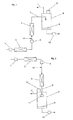
- the mixer-heat exchanger 4 is arranged in this example standing with lower input and upper output.
- a feed line 12 for an entrainer can be present between pressure reducer 3 and mixer-heat exchanger 4.
- a fluid mixture is supplied to the heat exchanger 2 by means of the feed pump 1. There, the fluid mixture is heated and built up a pressure. Subsequently, the fluid mixture is conveyed to the pressure reducer 3, where it is expanded to a first pressure P1 and thus passes into the mixer-heat exchanger 4. In the mixer-heat exchanger 4, it is reheated or maintained at the temperature and simultaneously mixed as described above evenly. There is a bumping and foaming instead. The resulting two-phase mixture is conducted via the connecting line 7 to the separation vessel 6 and rested there at a lower pressure P2 compared to the first pressure P1. The vapor 7 is led away via the trigger and collected the remaining mixture in the collecting area 9 and then carried away by means of the suction pump or the extruder 10.
- FIG. 2 the mixer-heat exchanger is also shown standing, here the input is located above and the output below. Same parts are given the same reference numbers as in FIG. 1 designated.
- a distributor 11 for example a shower, in order to distribute the fluid flowing into the separating vessel uniformly.
- manifolds 11 are known in the art.
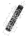
- FIG. 3 an example of a preferred mixer heat exchanger is shown. It is one of the above Fluitec mixer heat exchangers, as described in detail in the above patent publications. The other Fluitec mixer heat exchangers mentioned above can also be used.
- the mixer heat exchanger according to FIG. 3 Therefore, only briefly explained here:
- the mixer heat exchanger according FIG. 3 has an unillustrated outer tube with a flow channel for flowing media to be tempered.
- this outer tube is at least one mixing insert, preferably at least two mixing inserts are arranged with an integrated tube bundle 415.
- Each mixing insert 41, 42, 43, 44 consists of a plurality of web plates 47, 48, 49, 410, 411, 412, which form the mixing elements as a group.
- Each mixing insert 41, 42, 43, 44 has four intersecting web plates 47, 48 and eight shortened intersecting web plates 49, 410, 411, 412.
- the ratio of the maximum web width x to the pipe diameter Di is 0.25 and the ratio of the length L of a mixing element to the pipe diameter Di is 0.8 to 1.2 and the angle of the web plates to the tube axis is 42 ° to 48 °.
- the ratio of the vertical distance (y) in each mixing insert 41, 42, 43, 44 to the pipe diameter Di has a value of 0.2 to 0.4.
- the mixing inserts 41, 42, 43, 44 are arranged one behind the other in the flow channel, with the adjacent inserts relative to the longitudinal axis of the insert, i. the longitudinal axis of the tubes are rotated at an angle of 90 ° to each other.
- the individual mixing inserts can also be rotated in a different pattern. For example, Every third, fourth or fifth mixing insert can be rotated.
- the mixing inserts have ellipses into which at least one tube 45, 46 of the tube bundle 415 is inserted and fastened to the mixing insert.
- the tubes are soldered, for example, with the web plates.
- the comparative example is carried out in a conventional expansion evaporator with substantial relaxation in a flash tank.
- a heated to 120 ° fluid mixture consisting of water and dissolved sugar is released via a valve directly in the flash tank.
- the pressure P1 is from 3 bar to P2 100 mbar relaxed, which leads to a very strong foaming in the expansion tank.
- the foaming is so strong that the flash tank is suddenly filled with foam, so that no distillate can be removed via the vapors.
- the process must therefore be completely aborted.
- Increasing the pressure P2 in the flash tank the foaming slows down. Nevertheless, the process can not be performed with a high level of operational safety, as it always comes back to a violent foaming. Continuous process control is thus only possible with a minimum evaporation performance.
- the second application example relates to a degassing with the aid of the flash evaporator according to FIG. 2 ,
- the polymer solution is preheated in the heat exchanger 2, expanded in the Fluitec mixer heat exchanger 4 and separated in the separation vessel 6.
- Known entrainers are water, methanol, CO2, water vapor and nitrogen, which mixed with the mixer heat exchanger before the separation chamber, here the degassing chamber, respectively. be dispersed. Decisive for the construction of the system is the required input and residual concentration at the outlet from the flash evaporator.
- a residual amount of 600 to 1100 PPM without entrainer and a residual amount of 100 to 400 PPM can be achieved.
- the inventive expansion evaporator with additional heat source allows a gentle and reliable evaporation of a fluid mixture.
Landscapes
- Chemical & Material Sciences (AREA)
- Chemical Kinetics & Catalysis (AREA)
- Vaporization, Distillation, Condensation, Sublimation, And Cold Traps (AREA)
Abstract
Ein kontinuierlich arbeitender Entspannungsverdampfer für die Trennung eines Fluidgemischs weist einen Wärmeübertrager (2), einen Entspannungsbehälter und ein Trenngefäss (6) auf. Der Entspannungsbehälter ist durch einen Mischer-Wärmetauscher (4) gebildet, wobei der Mischer-Wärmetauscher (4) ein Aussenrohrmit mindestens einem im Aussenrohrangeordneten Mischeinsatz aufweist und wobei das Aussenrohr einen Strömungskanal bildet zur Aufnahme eines Vollstroms des Fluidgemischs. In Strömungsrichtung des Fluidgemischs nach dem Wärmeübertrager (2) und vor dem Mischer-Wärmetauscher (4) ist ein Druckreduzierer (3) vorhanden und das Trenngefäss (6) ist in Strömungsrichtung dem Mischer-Wärmetauscher (6) nachgeschaltet. Dieser Entspannungsverdampfer mit zusätzlicher Wärmequelle ermöglicht ein schonendes und betriebssicheres Verdampfen eines Fluidgemischs.A continuous expansion evaporator for the separation of a fluid mixture has a heat exchanger (2), a flash tank and a separating vessel (6). The expansion vessel is formed by a mixer heat exchanger (4), wherein the mixer heat exchanger (4) has an outer tube with at least one mixing insert arranged in the outer tube and wherein the outer tube forms a flow channel for receiving a full flow of the fluid mixture. In the flow direction of the fluid mixture after the heat exchanger (2) and before the mixer heat exchanger (4), a pressure reducer (3) is present and the separation vessel (6) downstream of the mixer-heat exchanger (6). This expansion evaporator with additional heat source enables a gentle and reliable evaporation of a fluid mixture.
Description
Die vorliegende Erfindung betrifft eine Vorrichtung und ein Verfahren zur Trennung eines Fluidgemischs mittels kontinuierlicher Entspannungsverdampfung sowie einen Entspannungsbehälter.The present invention relates to an apparatus and a method for separating a fluid mixture by means of continuous flash evaporation and a flash tank.
Durch Entspannungsverdampfung entsteht aus einem Fluidgemisch ein Dampf, in welchem sich leichter flüchtige Komponenten des Fluidgemischs anreichern. Die Entspannungsverdampfung ist somit eine einstufige Destillation, wobei in diesem Verfahren die Trennung des Fluidgemischs über eine oder mehrere Stufen erfolgen kann.By flash evaporation, a vapor is formed from a fluid mixture in which more volatile components of the fluid mixture accumulate. The flash evaporation is thus a one-stage distillation, in which process the separation of the fluid mixture can take place via one or more stages.
Üblicherweise wird das Fluidgemisch in einem Platten- oder Rohrbündelwärmetauscher bei einem Vordruck P1 erhitzt und anschließend auf einen niedrigeren Druck P2 (P2 < P1) in einem Entspannungs- und Trennbehälter entspannt. Die Entspannung erfolgt, wenn der Druck durch Freigeben eines Austrittsquerschnitts (z.B. einem Ventil, einer Düse, einer Blende, einer Verengung oder eines Rohres welches einen ausreichenden Druckverlust erzeugt) schlagartig abgesenkt wird. Im Entspannungs- und Trennbehälter kommt es so zur Entspannungsverdampfung, also zur Überhitzung der Flüssigkeit und damit zur Entstehung von Dampf. Die überhitzte Flüssigkeit und ihr Dampf befinden sich nicht mehr im Gleichgewicht. Dieser Zustand bedeutet, dass die Flüssigkeit Wärme abgeben muss - in diesem Falle geschieht das durch einen Energieeintrag an Siedekeime und schon vorhandene Dampfblasen im Entspannungs- und Trennbehälter. Dies führt zum Blasenwachstum und deren Aufstieg und schließlich zum Aufwallen der Flüssigkeit und zur Ausspeicherung von Masse und Energie in Form von Dampf - der Vorgang, der im Allgemeinen als "Kochen" bezeichnet wird. Der Dampf transportiert somit Energie aus dem Entspannungs- und Trennbehälter.Usually, the fluid mixture is heated in a plate or shell and tube heat exchanger at a pre-pressure P1 and then expanded to a lower pressure P2 (P2 <P1) in a flash and separation tank. The relaxation takes place when the pressure is abruptly lowered by releasing an outlet cross-section (eg a valve, a nozzle, a diaphragm, a constriction or a pipe which produces a sufficient pressure loss). In the expansion and separation tank it comes to the flash evaporation, ie the overheating of the liquid and thus the formation of steam. The overheated liquid and its vapor are no longer in balance. This condition means that the liquid must give off heat - in this case, this is done by an energy input to Siedekeime and already existing vapor bubbles in the expansion and separation tank. This leads to bubble growth and its ascent, and finally to liquid spewing and mass and energy depletion in the form of steam - the process commonly referred to as "cooking." The steam thus transports energy the relaxation and separation tank.
Typische Anwendungen der Entspannungsverdampfung sind:
- das Trennen von leicht flüchtigen Stoffen aus einer Flüssigkeit,
- das Eindicken von Fruchtsäften;
- die Herstellung von Hartbonbons;
- die Aufbereitung von Zucker;
- das Kochen einer Würze;
- die Aufbereitung von industriellem Abwasser;
- die Herstellung von Konzentraten;
- die Polykondensation von Kunststoffen sowie
- die Restentgasung von Polymeren.
- the separation of volatile substances from a liquid,
- the thickening of fruit juices;
- the production of hard candies;
- the processing of sugar;
- the cooking of a wort;
- the treatment of industrial waste water;
- the production of concentrates;
- the polycondensation of plastics as well
- the residual degassing of polymers.
Die Entspannungsverdampfung eignet sich somit zur Trennung einer Vielzahl von Fluidgemischen, welche je nach Zusammensetzung und Anwendungsbereich sehr unterschiedliche Viskositäten aufweisen können. Die Viskosität eines Fluidgemischs kann sich auch während des Prozesses verändern.The flash evaporation is thus suitable for the separation of a variety of fluid mixtures, which may have very different viscosities depending on the composition and application. The viscosity of a fluid mixture can also change during the process.
Die Entspannungsverdampfung ist ein sehr alter Prozess und wird insbesondere in unzähligen Patentpublikationen beschrieben.Flash evaporation is a very old process and is described in countless patent publications.
So zeigt beispielsweise die
Diese Art von Verdampfer eignet sich besonders für Fluidgemische mit geringer Viskosität.This type of evaporator is particularly suitable for fluid mixtures with low viscosity.
Es sind weitere Patentpublikationen bekannt, welche Strangverdampfer mit Rohrbündel-Wärmetauscher offenbaren, wobei die Rohre von dem zu erwärmenden Fluidgemisch durchströmt werden. Beispiele sind
In
Auch
Bei der Berechnung der Druckentlastung spielen Siedeverzug, Aufschäumen des Fluidgemischs durch Entspannungsverdampfung, Phasenseparation, kritisches Ausströmen sowie die thermo- und fluiddynamische Kopplung von Apparatekomponenten und - gruppen eine Rolle. Kenntnisse über diese physikalischen Vorgänge sind in der Regel nicht in ausreichendem Mass vorhanden, so dass stets längere Versuchsphasen notwendig sind, bis ein Trennungsprozess mit einer neuen Zusammensetzung eines Fluidgemischs die erwünschten Resultate bringt.In the calculation of the pressure relief, delayed settling, foaming of the fluid mixture by flash evaporation, phase separation, critical outflow as well as the thermo-fluid dynamic coupling of apparatus components and groups play a role. Knowledge of these physical processes is usually not to a sufficient degree, so that always longer test phases are necessary until a separation process with a new composition of a fluid mixture brings the desired results.
Ferner sind in
Der Erfindung liegt die Aufgabe zugrunde, einen verbesserten kontinuierlich arbeitenden Entspannungsverdampfer sowie ein Verfahren zur Trennung eines Fluidgemischs mittels kontinuierlicher Entspannungsverdampfung zu schaffen, welche eine hohe Betriebssicherheit gewährleisten und ein schonendes schaumarmes Entspannen sicherstellen.The invention has for its object to provide an improved continuously operating flash evaporator and a method for separating a fluid mixture by means of continuous flash evaporation, which ensure high reliability and ensure a gentle low-foaming relax.
Diese Aufgabe lösen ein Entspannungsverdampfer mit den Merkmalen des Anspruchs 1, ein Entspannungsbehälter mit den Merkmalen des Anspruchs 12 sowie ein Verfahren zur Entspannungsverdampfung mit den Merkmalen des Anspruchs 13.This object is achieved by a flash evaporator having the features of claim 1, a flash tank having the features of
Der erfindungsgemässe kontinuierlich arbeitende Entspannungsverdampfer für die Trennung eines Fluidgemischs weist einen Wärmeübertrager, einen Entspannungsbehälter und ein Trenngefäss auf. Der Entspannungsbehälter ist erfindungsgemäss durch einen Mischer-Wärmetauscher gebildet, wobei der Mischer-Wärmetauscher ein Aussenrohr mit mindestens einem im Aussenrohr angeordneten Mischeinsatz aufweist und wobei das Aussenrohr einen Strömungskanal bildet zur Aufnahme eines Vollstroms des Fluidgemischs. In Strömungsrichtung des Fluidgemischs nach dem Wärmeübertrager und vor dem Mischer-Wärmetauscher ist ein Druckreduzierer vorhanden und das Trenngefäss ist in Strömungsrichtung dem Mischer-Wärmetauscher nachgeschaltet.The inventive continuous expansion evaporator for the separation of a fluid mixture has a heat exchanger, a flash tank and a separation vessel. The expansion vessel according to the invention is formed by a mixer-heat exchanger, wherein the mixer-heat exchanger has an outer tube with at least one arranged in the outer tube mixing insert and wherein the outer tube forms a flow channel for receiving a full flow of the fluid mixture. In the flow direction of the fluid mixture after the heat exchanger and before the mixer-heat exchanger, a pressure reducer is present and the separation vessel is downstream of the mixer-heat exchanger in the flow direction.
Das erfindungsgemässe Verfahren zum Trennen eines Fluidgemischs mittels kontinuierlich arbeitender Entspannungsverdampfung weist mindestens folgende Schritte auf:
- Fördern eines Fluidgemischs mit Druckaufbau auf einen ersten Druck,
- Erwärmen des Fluidgemischs,
- Teilentspannen des erwärmten Fluidgemischs,
- Zuführen in einen Mischer-Wärmetauscher, wobei dem Fluidgemisch im Mischer-Wärmetauscher stetig Wärme zugeführt wird und wobei der Druck des sich im Mischer-Wärmetauscher befindlichen Fluidgemischs stetig abgesenkt wird und
- Restentgasung des Fluidgemischs bei einem zweiten Druck, welcher kleiner ist als der erste Druck in einem Trenngefäss, wobei ein Brüden aus dem Trenngefäss abgeleitet und ein Restgemisch des Fluidgemischs gesammelt wird.
- Conveying a fluid mixture with pressure buildup to a first pressure,
- Heating the fluid mixture,
- Partial relaxation of the heated fluid mixture,
- Feeding in a mixer-heat exchanger, wherein the fluid mixture in the mixer heat exchanger is continuously supplied with heat and wherein the pressure of the fluid mixture located in the mixer heat exchanger is steadily lowered and
- Residual degassing of the fluid mixture at a second pressure which is less than the first pressure in a separation vessel, wherein a vapor derived from the separation vessel and a residual mixture of the fluid mixture is collected.
Vorzugsweise wird das Fluidgemisch im Mischer-Wärmetauscher über die Länge und Breite des Mischer-Wärmetauschers global gemischt und um 90° umgelenkt.Preferably, the fluid mixture is mixed globally in the mixer heat exchanger over the length and width of the mixer-heat exchanger and deflected by 90 °.
Das Fluidgemisch besteht üblicherweise aus einem Gemisch von zwei oder mehr Flüssigkeiten oder mindestens einem Gas und mindestens einer Flüssigkeit oder Festkörpern und mindestens einer Flüssigkeit.The fluid mixture usually consists of a mixture of two or more liquids or at least one gas and at least one liquid or solids and at least one liquid.
Im erfindungsgemässen Entspannungsverdampfer und im erfindungsgemässen Verfahren sind der Siedeverzug und das Aufschäumen in den Mischer-Wärmetauscher verlagert. Dieser bildet einerseits eine zusätzliche Wärmequelle, welche dem Fluidgemisch genügend Wärme homogen zuführen kann. Andererseits ermöglicht er eine globale Vermischung über seinen ganzen Querschnitt, was zu einer frühzeitigen Koaleszenz führt. Dies verhindert ein zu heftiges und ungewolltes Aufschäumen. Der erfindungsgemässe Entspannungsverdampfer ermöglicht so ein schonendes, schaumarmes und betriebssicheres Verdampfen bei einer definierten Entspannung.In the flash evaporator according to the invention and in the process according to the invention, the boiling delay and the foaming are shifted into the mixer heat exchanger. On the one hand, this forms an additional heat source, which can homogeneously supply enough heat to the fluid mixture. On the other hand, it enables global mixing over its entire cross-section, leading to early coalescence. This prevents too vigorous and unwanted foaming. The inventive expansion evaporator thus enables gentle, low-foaming and reliable evaporation at a defined relaxation.
Vorteilhaft ist zudem, dass der erfindungsgemässe Entspannungsverdampfer eine verbesserte Leistung bezüglich des Misch- und Verweilzeitverhaltens sowie auch des Wärmetauschs an den lokalen kritischen Stellen während der Entspannung aufweist.It is also advantageous that the expansion evaporator according to the invention has an improved performance with regard to the mixing and retention behavior as well as the heat exchange at the local critical points during the expansion.
Vorzugsweise weist der Mischer-Wärmetauscher eine Längsachse auf, welche eine Hauptströmungsrichtung innerhalb des Mischer-Wärmetauschers definiert, wobei die flüssigkeitsdurchströmbaren Querschnitte des Mischer-Wärmetauscher in dieser Hauptströmungsrichtung über annähernd die gesamte Länge des Mischer-Wärmetauschers derart gewählt sind, dass die Maldistribution minimiert und die Verweilzeitverteilung eng ist.Preferably, the mixer heat exchanger has a longitudinal axis defining a main flow direction within the mixer heat exchanger, wherein the liquid flow cross sections of the mixer heat exchanger in this main flow direction over approximately the entire length of the mixer heat exchanger are selected such that the Maldistribution minimized and the Residence time distribution is tight.
Vorzugsweise weist der Mischer-Wärmetauscher mindestens zwei in seiner Längsrichtung hintereinander angeordnete Mischelemente auf, welche um 90° zueinander gedreht sind. Die einzelnen Mischelemente sind vorzugsweise fest miteinander verbunden und sie sind bis auf ihre gedrehte Anordnung vorzugsweise identisch ausgebildet. Ein Mischelement weist vorzugsweise ein sich nicht wiederholendes Muster in der Anordnung der Umlenkelemente auf, welches sich erst im nächsten Mischelement wiederholt. Dank dieser Anordnung mischt der Mischer-Wärmetauscher das durchströmende Fluidgemisch über annähernd die gesamte Länge des Mischer-Wärmetauschers und über seine gesamten flüssigkeitsdurchströmten Querschnitte stetig und mit sich ändernden Radialrichtungen.Preferably, the mixer-heat exchanger at least two mixing elements arranged one behind the other in its longitudinal direction, which are rotated by 90 ° to each other. The individual mixing elements are preferably firmly connected to each other and they are preferably identical except for their rotated arrangement. A mixing element preferably has a non-repeating pattern in the arrangement of the deflecting elements, which repeats itself only in the next mixing element. Thanks to this arrangement, the mixer-heat exchanger mixes the fluid mixture flowing through over almost the entire length of the mixer-heat exchanger and over its entire liquid-flow cross sections steadily and with changing radial directions.
Benachbarte Mischeinsätze können gleich ausgerichtet sein oder jeweils um 90° zueinander versetzt sein. So entstehen Anordnungen, bei welchen zum Beispiel 10 Mischelemente nacheinander angeordnet sind und jeweils um 90° versetzt sind. Es lassen sich jedoch auch jedes, jedes zweite, dritte oder n-te Element drehen.Adjacent mixing inserts can be aligned the same or each offset by 90 ° to each other. This results in arrangements in which, for example, 10 mixing elements are arranged one after the other and each offset by 90 °. However, every second, third or nth element can also be rotated.
Die Länge einer Mischstrecke (auch Mischer genannt) bestehend aus einem oder mehreren gleich ausgerichteten Mischelementen beträgt vorzugsweise annähernd das Vierfache der Breite des Mischeinsatzes, noch bevorzugter annähernd das Doppelte und am bevorzugtesten entspricht die Länge dieser Mischstrecke bzw. Mischers annähernd Breite des Mischeinsatzes.The length of a mixing section (also called mixer) consisting of one or more identically aligned mixing elements is preferably approximately four times that of Width of the mixing insert, more preferably approximately twice, and most preferably, the length of this mixing section or mixer corresponds approximately to the width of the mixing insert.
Dank dieses Mischers-Wärmetauschers entsteht ein einzigartiges, intensives, radiales Mischen über den ganzen Produkteraum. Diese Mischleistung lässt sich bei der Entspannungsverdampfung nutzen, um die Blasen im aufschäumenden Fluidgemisch zu kontaktieren und zu verbinden, resp. zu kolaeszieren.Thanks to this mixer heat exchanger, a unique, intensive, radial mixing is created across the entire product chamber. This mixing performance can be used in the flash evaporation to contact the bubbles in the foaming fluid mixture and connect, respectively. to colise.
In einer bevorzugten Ausführungsform weist der Mischer-Wärmetauscher mindestens einen Mischeinsatz und ein Rohrbündel auf, wobei der Mischer-Wärmetauscher Stegplatten aufweist, wobei das Rohrbündel aus mehreren Rohren gebildet ist, welche sich in Längsrichtung des Mischer-Wärmetauschereinsatzes erstrecken, und wobei die Stegplatten in einem schrägen Winkel zu den Rohren angeordnet und mit diesen fest verbunden sind. Die Stegplatten eines Mischeinsatzes bilden vorzugsweise das oben genannte Mischelement. Die Mischeinsätze sind vorzugsweise um 90° versetzt zueinander angeordnet.In a preferred embodiment, the mixer heat exchanger has at least one mixing insert and a tube bundle, the mixer heat exchanger having web plates, wherein the tube bundle is formed of a plurality of tubes extending in the longitudinal direction of the mixer heat exchanger insert, and wherein the web plates in a arranged oblique angle to the tubes and are firmly connected with these. The web plates of a mixing insert preferably form the above-mentioned mixing element. The mixing inserts are preferably arranged offset by 90 ° to each other.
Vorzugsweise reichen mindestens ein Teil der Stegplatten durch das Rohrbündel hindurch. Vorzugsweise sind die Stegplatten paarweise gekreuzt zueinander angeordnet. Die Rohre sind von einem Wärmeträgermedium durchströmbar und werden vom zu temperierenden Fluidgemisch umströmt.Preferably, at least a portion of the web plates extend through the tube bundle. Preferably, the web plates are arranged in pairs crossed to each other. The tubes are flowed through by a heat transfer medium and are flowed around by the fluid mixture to be tempered.
Dieser Mischer-Wärmetauscher weist die grosse Wärmeübertragungskapazität eines Rohrbündelapparates auf. Der Produktstrom wird jedoch nicht in Parallelströme aufgeteilt, so dass der radiale Mischeffekt über den gesamten Produktstrom erfolgt.This mixer heat exchanger has the large heat transfer capacity of a tube bundle apparatus. However, the product stream is not split into parallel streams so that the radial mixing effect occurs throughout the product stream.
Besonders geeignet sind die oben erwähnten sogenannten Fluitec Mischer-Wärmetauscher. Diese Fluitec Mischer-Wärmetauscher weisen spezielle Mischereinbauten auf und ermöglichen eine strömungstechnische Beherrschung der Quervermischung und der Oberflächenerneuerung. Diese Mischer-Wärmetauscher eignen sich somit insbesondere sowohl für chemische Reaktionen (z.B. Polymerisationen, Polykondensationen) mit Wärmetönung als auch für Temperiervorgänge (Erwärmung oder Kühlung) von hochviskosen Flüssigkeiten.Particularly suitable are the above-mentioned so-called Fluitec mixer heat exchangers. These Fluitec mixer heat exchangers have special mixer installations and allow fluidic control of cross mixing and surface renewal. These mixer-heat exchangers are thus suitable in particular both for chemical reactions (eg, polymerizations, polycondensations) with heat of reaction and for tempering processes (heating or cooling) of highly viscous liquids.
Fluitec Mischer-Wärmetauscher verfügen über eine sehr hohe Mischleistung. Aufgrund der sehr hohen erzielten Nusselt-Zahl sowie der grossen Oberfläche besitzen diese Mischer-Wärmetauscher ein ausgezeichnetes volumenbezogenes Wärmeübertragungsvermögen. Um die Mischleistung im Fluitec Wärmetauscher zu gewährleisten, weist er üblicherweise eine eher schlanke Form auf. Beispielsweise lassen sich Betriebsdrücke von 300 bar bei einer Temperatur von 300°C konstruktiv realisieren. Zahlreiche Untersuchungen haben auch gezeigt, dass Fluitec Mischer-Wärmetauscher ein ausgezeichnetes Verweilzeitverhalten aufweisen. Einige der konstruktiven Merkmale der Fluitec Mischer-Wärmetauscher sind stichwortartig beschrieben die Folgenden:
- die Mischer-Wärmetauscher-Fläche ist als Paket ausbaubar;
- die gesamte Oberfläche kann kontrolliert gereinigt und auch sterilisiert werden;
- der Mischer-Wärmetauscher-Querschnitt ist in der Hauptströmungsrichtung des Fluidgemischs geometrisch überall definiert und reduziert die Maldistribution auf ein Minimum, so dass eine enge Verweilzeitverteilung gewährleistet ist;
- durch die hohe volumenspezifische Wärmeübeitragungsfläche sind die Fluitec Mischer-Wärmetauscher für hochviskose Flüssigkeiten und für temperatursensitive Medien besonders geeignet.
- the mixer heat exchanger surface is removable as a package;
- the entire surface can be cleaned and sterilized in a controlled manner;
- the mixer-heat exchanger cross-section is geometrically defined everywhere in the main flow direction of the fluid mixture and minimizes the distribution of maldistribles, thus ensuring a narrow residence time distribution;
- The high volume-specific heat transfer surface makes the Fluitec mixer heat exchangers particularly suitable for high-viscosity liquids and temperature-sensitive media.
Es hat sich nun gezeigt, dass sich diese besonderen Eigenschaften vorteilhaft in der kontinuierlich arbeitenden Entspannungsverdampfung auswirken. Dadurch lässt sich der Mischer-Wärmetauscher als eine Art Entspannungsgefäss in einem Entspannungsverdampfer einsetzen.It has now been shown that these special properties have an advantageous effect in the continuous expansion evaporation. As a result, the mixer-heat exchanger can be used as a kind of expansion vessel in a flash evaporator.
Infolge des stetigen Druckverlusts im Mischer-Wärmetauscher, insbesondere im Fluitec Mischer-Wärmetauscher, erfolgt die Verdampfung der flüchtigen Anteile des Fluidgemischs äusserst schonend. Dank der stetigen Zugabe von Wärme über die Länge des Mischer-Wärmetauschers kann die Temperatur des Fluidgemischs nicht mit gleicher Geschwindigkeit abkühlen wie sich der Druck entspannt, da die Temperaturänderung den Wärme- und Stoffübertragungsmechanismen an der Phasengrenzfläche Wasser/Dampf unterliegt, welche langsamer verlaufen. Ein entstehender Siedezeitverzug kann somit zur Erhöhung der Verdampfungsleistung genutzt werden. Dadurch kann wiederum ein tieferer Entspannungsdruck im Trennungsgefäss verwendet werden. Dieser kann so tief gewählt werden, dass hochviskose Gemische nicht einfrieren.As a result of the constant pressure loss in the mixer-heat exchanger, in particular in the Fluitec mixer heat exchanger, the evaporation of the volatile components of the fluid mixture takes place extremely gently. Thanks to the steady addition of heat over the length of the mixer-heat exchanger, the temperature of the fluid mixture can not cool down at the same rate as the pressure relaxes because the temperature change is subject to the heat and mass transfer mechanisms at the water / vapor interface, which are slower. An emerging boiling time delay can thus be used to increase the evaporation capacity. This can in turn be a deeper Relaxation pressure can be used in the separation vessel. This can be chosen so deep that high-viscosity mixtures do not freeze.
Entstehende Dampfblasen koaleszieren im Mischer-Wärmetauscher, da das Fluidgemisch über annähernd die gesamte Länge des Mischer-Wärmetauschers und über den gesamten durchströmten Querschnitt stetig sowie mit sich ändernden Radialrichtungen gemischt wird. Dadurch wird das Gemisch stets innig kontaktiert und seine Temperatur wird maximal homogenisiert.
In einer bevorzugten Ausführungsform ist zwischen dem Mischer-Wärmetauscher und dem Trenngefäss eine Verbindungsleitung, insbesondere ein Verbindungsrohr vorhanden. Dies ermöglicht einen schaumarmen Austrag der Zweiphasenströmung in das Trenngefäss.Resulting vapor bubbles coalesce in the mixer-heat exchanger, since the fluid mixture is mixed over almost the entire length of the mixer-heat exchanger and over the entire flow-through cross-section continuously and with changing radial directions. As a result, the mixture is always intimately contacted and its temperature is maximized homogenized.
In a preferred embodiment, a connecting line, in particular a connecting tube, is present between the mixer-heat exchanger and the separating vessel. This allows a low-foam discharge of the two-phase flow in the separation vessel.
Üblicherweise ist eine Förderpumpe vorhanden zum Fördern des Fluidgemischs und zum Aufbau eines ersten Drucks, wobei die Förderpumpe in Strömungsrichtung vor dem Wärmeübertrager angeordnet ist.Usually, a feed pump is provided for conveying the fluid mixture and for establishing a first pressure, wherein the feed pump is arranged upstream of the heat exchanger in the flow direction.
Als Wärmeübertrager zum Heizen des Fluidgemischs eignen sich bekannte, insbesondere kontinuierlich arbeitende Wärmeübertrager, wie beispielsweise Rohrbündel- oder Platten-Wärmetauscher sowie Mischer-Wärmetauscher für besonders sensitive .FluidgemischeSuitable heat exchangers for heating the fluid mixture are known, in particular continuously operating heat exchangers, such as tube bundle or plate heat exchangers and mixer heat exchangers for particularly sensitive .Fluidgemische
Als Druckreduzierer eignen sich ebenfalls die bekannten Mittel, wie beispielsweise ein Ventil, eine Düse, eine Blende, ein Lochplatte oder eine Verengung.Also suitable as pressure reducers are the known means, such as a valve, a nozzle, a diaphragm, a perforated plate or a constriction.
Das Trenngefäss ist ein Gefäss mit gegenüber dem Mischer-Wärmetauscher vergrössertem Volumen, beispielsweise ein bekanntes Entspannungsgefäss. In diesem Trenngefäss findet eine Restentspannung statt. Es weist üblicherweise einen Abzug oder eine Ableitung für den Brüden und einen Sammelbereich für das Restgemisch, d.h. den Sumpf, auf. Der Sumpf kann über ein Förderorgan, üblicherweise eine Pumpe oder ein Extruder, zu weiteren Prozessvorrichtungen gefördert werden.The separation vessel is a vessel with an enlarged volume compared to the mixer heat exchanger, for example a known expansion vessel. In this separation vessel, a residual relaxation takes place. It usually has a vent or drain for the vapor and a collection area for the residual mixture, i. the swamp, up. The sump can be conveyed via a conveyor, usually a pump or an extruder, to other process devices.
Der Mischer-Wärmetauscher kann stehend oder liegend angeordnet sein. Ist er stehend angeordnet, so befindet sich sein Eingang unten und sein Ausgang oben bzw. umgekehrt. Optional kann im Trenngefäss ein Füllstandsensor zur Detektion oder Messung eines Füllstandes vorhanden sein. Die Detektion oder Messung kann beispielsweise mittels Radar erfolgen. Optional kann dem Fluidgemisch vor dem Mischer-Wärmetauscher ein Schleppmittel zugegeben werden. Optional wird das Fluidgemisch im Mischer-Wärmetauscher in einen metastabilen Bereich verdampft, so dass es im Fluidgemisch zu einer kontrollierten Kristallbildung kommt.The mixer-heat exchanger can be arranged standing or lying. If he is standing, his entrance is at the bottom and his exit at the top or vice versa. Optionally, a fill level sensor for detecting or measuring a fill level may be present in the separation vessel. The detection or measurement can be done for example by means of radar. Optionally, an entraining agent may be added to the fluid mixture prior to the mixer heat exchanger. Optionally, the fluid mixture is evaporated in the mixer-heat exchanger in a metastable region, so that it comes in the fluid mixture to a controlled crystal formation.
Optional kann die Vorrichtung zwei- oder mehrstufig ausgebildet sein, wobei jeweils einem Mischer-Wärmetauscher ein Trenngefäss folgt und anschliessend wiederum ein oder mehrerer Paare von Mischer-Wär-metauschern und Trenngefässen angeordnet sind. Dazwischen können optional weitere Druckreduzierer angeordnet sein.Optionally, the device may be formed in two or more stages, wherein in each case a mixer-heat exchanger is followed by a separation vessel and then in turn one or more pairs of mixer-heat exchangers and separation vessels are arranged. In between, optionally further pressure reducers can be arranged.
Weitere Vorteile, Merkmale und Einzelheiten der Erfindung ergeben sich aus der nachfolgenden Beschreibung bevorzugter Ausführungsbeispiele sowie anhand der Zeichnung, die lediglich zur Erläuterung dient und nicht einschränkend auszulegen ist. Die Zeichnung zeigt schematisch in
- Figur 1
- einen erfindungsgemässen Entspannungsverdampfer in einer ersten Ausführungsform;
Figur 2- einen erflndungsgemässen Entspannungsverdampfer in einer zweiten Ausführungsform und
Figur 3- ein Fluitec Mischer-Wärmetauscher in einer ersten Ausführungsform.
- FIG. 1
- an inventive expansion evaporator in a first embodiment;
- FIG. 2
- a discharge according to the invention expansion evaporator in a second embodiment and
- FIG. 3
- a Fluitec mixer heat exchanger in a first embodiment.
-
Figur 1 zeigt einen erfindungsgemässen Entspannungsverdampfer mit einer Förderpumpe 1, einem Wärmeübertrager 2, einem Druckreduzierer 3, einem Mischer-Wärmetauscher 4, einer Verbindungsleitung 5 und einem Trenngefäss 6. Der untere Bereich des Trenngefässes 6 bildet einen Sammelbereich 9. In einem oberen Bereich, vorzugsweise im obersten Bereich ist eine Ableitung oder ein Abzug 7 vorhanden. Optional kann ein Füllstandsensor 8 vorhanden sein.FIG. 1 shows an inventive expansion evaporator with a feed pump 1, aheat exchanger 2, apressure reducer 3, a mixer-heat exchanger 4, a connectingline 5 and a separating vessel 6. The lower region of the separating vessel 6 forms a collecting region 9. In an upper region, preferably in the uppermost region, a discharge or atrigger 7 is present. Optionally, alevel sensor 8 may be present.
Der Mischer-Wärmetauscher 4 ist in diesem Beispiel stehend mit unterem Eingang und oberen Ausgang angeordnet.The mixer-heat exchanger 4 is arranged in this example standing with lower input and upper output.
Optional kann zwischen Druckreduzierer 3 und Mischer-Wärmetauscher 4 eine Zuleitung 12 für ein Schleppmittel vorhanden sein.Optionally, a
Ein Fluidgemisch wird mittels der Förderpumpe 1 dem Wärmeübertrager 2 zugeführt. Dort wird das Fluidgemisch erhitzt und ein Druck aufgebaut. Anschliessend wird das Fluidgemisch zum Druckreduzierer 3 gefördert, wo es auf einen ersten Druck P1 entspannt wird und so in den Mischer-Wärmetauscher 4 gelangt. Im Mischer-Wärmetauscher 4 wird es wieder erwärmt oder auf der Temperatur gehalten und gleichzeitig wie bereits oben beschrieben gleichmässig durchmischt. Es finden ein Siedeverzug und ein Aufschäumen statt. Das entstandene Zweiphasengemisch wird über die Verbindungsleitung 7 zum Trenngefäss 6 geführt und dort bei einem im Vergleich zum ersten Druck P1 tieferen Druck P2 restentspannt. Der Brüden 7 wird über den Abzug weggeleitet und das Restgemisch im Sammelbereich 9 gesammelt und anschliessend mittels der Saugpumpe oder dem Extruder 10 weggefördert.A fluid mixture is supplied to the
In
In
Der Mischer-Wärmetauscher gemäss
Jeder Mischeinsatz 41, 42, 43, 44 besteht aus mehreren Stegplatten 47, 48, 49, 410, 411, 412, welche als Gruppe die Mischelemente bilden. Jeder Mischeinsatz 41, 42, 43, 44 weist vier sich kreuzend hindurchreichende Stegplatten 47,48 und acht gekürzte sich kreuzende Stegplatten 49, 410, 411, 412 auf. Das Verhältnis der maximalen Stegbreite x zum Rohrdurchmesser Di beträgt 0.25 und das Verhältnis der Länge L eines Mischelementes zum Rohrdurchmesser Di beträgt 0.8 bis 1.2 und der Winkel der Stegplatten zur Rohrachse beträgt 42° bis 48°. Zusätzlich weist das Verhältnis des senkrechten Abstandes (y) in jedem Mischeinsatz 41, 42, 43, 44 zum Rohrdurchmesser Di einen Wert von 0.2 bis 0.4 auf. Die Mischeinsätze 41, 42, 43, 44 sind im Strömungskanal hintereinander angeordnet, wobei die aneinander grenzenden Einsätze bezüglich der Längsachse des Einsatzes, d.h. der Längsachse der Rohre, um einen Winkel von 90° gegeneinander verdreht sind. Wie bereits oben erwähnt lassen sich die einzelnen Mischeinsätze auch in einem anderen Muster drehen. Z.B. kann jeder dritte, vierte oder fünfte Mischeinsatz gedreht sein.Each mixing
Die Mischeinsätze besitzen Ellipsen, in welche man mindestens einen Rohr 45, 46 des Rohrbündels 415 einschiebt und am Mischeinsatz befestigt. Die Rohre sind beispielsweise mit den Stegplatten verlötet.The mixing inserts have ellipses into which at least one
Im Folgenden werden zwei Anwendungsbeispiele sowie ein Vergleichsbeispiel genannt:In the following two application examples and a comparative example are mentioned:
Das Vergleichsbeispiel wird in einem konventionellen Entspannungsverdampfer mit wesentlicher Entspannung in einem Entspannungsbehälter durchgeführt. Ein auf 120° erhitztes Fluidgemisch bestehend aus Wasser und gelöstem Zucker wird über ein Ventil direkt im Entspannungsbehälter entspannt. Der Druck P1 wird von 3 bar auf P2 100 mbar entspannt, was zu einem sehr starken Aufschäumen im Entspannungsbehälter führt. Das Aufschäumen ist so stark, dass der Entspannungsbehälter schlagartig mit Schaum gefüllt ist, so dass kein Destillat über den Brüden abgeführt werden kann. Der Prozess muss somit vollständig abgebrochen werden. Erhöht man den Druck P2 im Entspannungsbehälter, so verlangsamt sich das Aufschäumen. Trotzdem kann der Prozess nicht mit einer hohen Betriebssicherheit geführt werden, da es immer wieder zu einem heftigen Aufschäumen kommt. Eine kontinuierliche Prozessführung ist somit nur bei einer minimalen Verdampfungsleistung möglich.The comparative example is carried out in a conventional expansion evaporator with substantial relaxation in a flash tank. A heated to 120 ° fluid mixture consisting of water and dissolved sugar is released via a valve directly in the flash tank. The pressure P1 is from 3 bar to P2 100 mbar relaxed, which leads to a very strong foaming in the expansion tank. The foaming is so strong that the flash tank is suddenly filled with foam, so that no distillate can be removed via the vapors. The process must therefore be completely aborted. Increasing the pressure P2 in the flash tank, the foaming slows down. Nevertheless, the process can not be performed with a high level of operational safety, as it always comes back to a violent foaming. Continuous process control is thus only possible with a minimum evaporation performance.
Es wird die Vorrichtung gemäss
Das zweite Anwendungsbeispiel betrifft eine Entgasung mit Hilfe des Entspannungsverdampfers gemäss
Da bei einer Polymerisation der chemische Umsatz nicht vollständig abläuft, findet man im polymerisierten Produkt noch Monomere, Oligomere, Abbau- und Zersetzungsprodukte sowie die verschiedensten Additive. Diese Bestandteile müssen dem Polymer zum Verbessern der Produktequalität (Trübung, Geruch, Festigkeit), zum Vermeiden gesundheitlicher Schädigung (aggressive Medien) und zum Verringern der Kosten (Rohstoffrückgewinnung) entzogen werden. Im weitesten Sinne nennt man in der Kunststofftechnik die Einheitsoperation zur Entfernung solcher flüchtigen Bestandteile aus Gas/Flüssig-, Flüssig/Flüssig- und Fest/Flüssiggemischen Entgasen.Since in a polymerization, the chemical conversion is not complete, can be found in the polymerized product nor monomers, oligomers, degradation and decomposition products and a variety of additives. These ingredients must be avoided by the polymer to improve product quality (haze, odor, strength) damage to health (aggressive media) and to reduce costs (raw material recovery). In the broadest sense, in plastics engineering, the unit operation for the removal of such volatile constituents from gas / liquid, liquid / liquid and solid / liquid mixtures is called degassing.
Im erfindungsgemässen Entspannungsverdampfer gemäss
Da Polymere in der Regel sehr viskos sind und Viskositäten bis 50'000 Pas aufweisen können, haben zusätzliche Effekte auf die Verdampfung einen Einfluss. Neben dem Niveau des Unterdruckes im Verdampfer hängt das Entgasungsergebnis einerseits von der Leistung des Wärmetauschers 2 sowie von der Bauart des Entgasungsapparates ab. Andererseits sind folgende Zusammenhänge gerade bei steigender Viskosität zu beachten:
- Mit zunehmender Phasengrenzfläche und abnehmender Schichtdicke steigt die Entgasungsleistung an. Phasengrenzfläche und Schichtdicke werden direkt durch die Abmessung und die Geometrie der Entgasungsvorrichtung bestimmt. Es ist daher vorteilhaft, das Polymer in der Trennkammer 6
über den Verteiler 11 in dünne Schichten zu verteilen, so dass eine effiziente Entgasung gewährleistet ist. - Mit zunehmender Temperatur steigt die Entgasungsleistung an, allerdings sind der Temperatur wegen der üblicherweise einsetzenden Produkteschädigung Grenzen gesetzt. Daher ist der Einsatz einer zusätzlichen Wärmequelle, d.h. des Mischer-Wärmetauschers 4 vorteilhaft, welcher insbesondere global über den ganzen Querschnitt und alternierenden in quer zur Längsachse mischen kann, so dass der Wärmeeintrag homogen erfolgt. Insbesondere die Verwendung des Fluitec Mischer-Wärmetauscher hat sich hier bewährt.
- Mit abfallendem Druck steigt die Entgasungsleistung an. Unterdrücke von 5 - 200 mbar sind speziell in der Ausführungsform gemäss
Figur 2 vorteilhaft. Bei zu grossen Dampfgeschwindigkeiten kann es jedoch zum Mitreissen von Polymerschmelze in den Entgasungsschacht, d.h.dem Abzug 7 führen. Daher ist eine Teilentgasung im Mischer-Wärmetauscher 4, insbesondere im Fluitec Mischer-Wärmetauscher, besonders vorteilhaft. - Zunehmende Verweilzeit des Gutes in der Entgasungskammer beeinflusst die Entgasungsleistung positiv. Allerdings muss das Verweilzeitspektrum eng gewählt werden, da sich Depolymerisationseffekte negativ auf die Entgasungsleistung auswirken können. Wird nun ein Teil der Entgasung in den Mischer-Wärmetauscher 4, insbesondere im Fluitec Mischer-Wärmetauscher, verlagert und dabei eine Strömungsrichtung von oben nach unten berücksichtigt, so bleibt die Verweilzeit bei hoher Entgasungsleistung kurz und das Verweilzeitspektrum sehr eng. Dies insbesondere deshalb, wenn der Querschnitt des Mischer-Wärmetauschers in der Hauptströmungsrichtung geometrisch überall so definiert ist, dass die Maldistribution auf ein Minimum reduziert wird und dass eine enge Verweilzeitverteilung gewährleistet ist. Dieser Aufbau begünstigt die Leistung des Entspannungsverdampfers besonders.
- Mit dem Einsatz von Schleppmitteln lässt sich der Molanteil der abzutrennenden Komponente in der Dampfphase reduzieren. Die Entgasungsleistung steigt dadurch an, da dies zu einer Reduktion der Gleichgewichtskonzentration führt. Da der Mischer-Wärmetauscher 4, insbesondere der Fluitec-Mischer Wärmetauscher, gleichzeigt die Wärmezufuhr bei globaler homogener Mischleistung sicherstellt, können optional vor dem Mischer-Wärmetauscher 4 zusätzliche Schleppmittel zugegeben werden. Der Zusatz von Schleppmittel kann den Einsatz einer Einstufigen Entspannungsverdampfung ermöglichen. Eine zweistufige Ausführung, d.h. eine Verwendung von zwei Paaren aufeinanderfolgender Mischer-Wärmetauscher/Trenngefässen ist in Ausnahmefällen auch denkbar.
- With increasing phase interface and decreasing layer thickness, the degassing increases. Phase interface and layer thickness are determined directly by the dimension and the geometry of the degassing device. It is therefore advantageous to distribute the polymer in the separation chamber 6 via the
distributor 11 into thin layers, so that efficient degassing is ensured. - As the temperature increases, the degassing power increases, but the temperature is limited due to the usually onset of product damage. Therefore, the use of an additional heat source, ie the mixer-heat exchanger 4 is advantageous, which in particular can mix globally over the entire cross-section and alternating in transverse to the longitudinal axis, so that the heat input is homogeneous. In particular, the use of the Fluitec mixer heat exchanger has proven itself here.
- With decreasing pressure, the degassing power increases. Underpressures of 5-200 mbar are especially in the embodiment according to
FIG. 2 advantageous. At too high vapor velocities, however, it can lead to the entrainment of polymer melt in the degassing shaft, ie thetrigger 7. Partial degassing in the mixer-heat exchanger 4, in particular in the Fluitec mixer-heat exchanger, is therefore particularly advantageous. - Increasing residence time of the material in the degassing chamber affects the Degassing performance positive. However, the residence time spectrum must be narrow because depolymerization effects can negatively impact degassing performance. If now a part of the degassing in the mixer-heat exchanger 4, in particular in the Fluitec mixer-heat exchanger, displaced while a direction of flow from top to bottom, so the dwell time at high degassing performance remains short and the residence time spectrum is very narrow. This is especially true if the cross-section of the mixer-heat exchanger in the main flow direction is defined geometrically everywhere, so that the Maldistribution is reduced to a minimum and that a narrow residence time distribution is ensured. This structure particularly favors the performance of the flash evaporator.
- With the use of entrainers, the mole fraction of the component to be separated can be reduced in the vapor phase. The degassing performance increases because it leads to a reduction of the equilibrium concentration. Since the mixer heat exchanger 4, in particular the Fluitec mixer heat exchanger, gleichzeigt the heat supply ensures a global homogeneous mixing performance, 4 additional entraining agents can optionally be added before the mixer heat exchanger. The addition of entraining agent may allow the use of one-stage flash evaporation. A two-stage design, ie a use of two pairs of successive mixer heat exchangers / separation vessels is also conceivable in exceptional cases.
Bekannte Schleppmittel sind Wasser, Methanol, CO2, Wasserdampf und Stickstoff, welche mit dem Mischer-Wärmetauscher vor der Trennkammer, hier die Entgasungskammer, eingemischt resp. eindispergiert werden. Entscheidend für den Aufbau des Systems ist die geforderte Eingangs- und Restkonzentration am Austritt aus dem Entspannungsverdampfer.Known entrainers are water, methanol, CO2, water vapor and nitrogen, which mixed with the mixer heat exchanger before the separation chamber, here the degassing chamber, respectively. be dispersed. Decisive for the construction of the system is the required input and residual concentration at the outlet from the flash evaporator.
So kann beispielsweise bei einem Polystyrolgemisch mit 20% leichtflüchtigen Dämpfen mit einem Differenzdruck von max. 10 bar ein Restmengenanteil von 600 bis 1100 PPM ohne Schleppmittel und ein Restmengenanteil von 100 bis 400 PPM erreicht werden.For example, in a polystyrene mixture with 20% volatile vapors with a differential pressure of max. 10 bar a residual amount of 600 to 1100 PPM without entrainer and a residual amount of 100 to 400 PPM can be achieved.
Der erfindungsgemässe Entspannungsverdampfer mit zusätzlicher Wärmequelle ermöglicht ein schonendes und betriebssicheres Verdampfen eines Fluidgemischs.The inventive expansion evaporator with additional heat source allows a gentle and reliable evaporation of a fluid mixture.
- 11
- Förderpumpefeed pump
- 22
- WärmeübertragerHeat exchanger
- 33
- Druckreduziererpressure reducer
- 44
- Mischer-WärmetauscherMixer-heat exchanger
- 4141
- Mischeinsatzmixed use
- 4242
- Mischeinsatzmixed use
- 4343
- Mischeinsatzmixed use
- 4444
- Mischeinsatzmixed use
- 4545
- Rohrpipe
- 4646
- Rohrpipe
- 4949
- Stegplatteweb plate
- 410410
- Stegplatteweb plate
- 411411
- Stegplatteweb plate
- 412412
- Stegplatteweb plate
- 415415
- Rohrbündeltube bundle
- 55
- Verbindungsrohrconnecting pipe
- 66
- Trenngefässseparation vessel
- 77
- Ableitung für den BrüdenDerivation for the vapors
- 88th
- Füllstandssensorlevel sensor
- 99
- Sammelbereich für den SumpfCollection area for the sump
- 1010
- Förderorganconveying member
- 1111
- Verteilerdistributor
- 1212
- SchleppmittelzuleitungEntraining agent supply line
Claims (15)
dass der Entspannungsbehälter durch einen Mischer-Wärmetauscher (4) gebildet ist, wobei der Mischer-Wärmetauscher (4) ein Aussenrohr mit mindestens einem im Aussenrohr angeordneten Mischeinsatz aufweist und wobei das Aussenrohr einen Strömungskanal bildet zur Aufnahme eines Vollstroms des Fluidgemischs,
dass in Strömungsrichtung des Fluidgemischs nach dem Wärmeübertrager (2) und vor dem Mischer-Wärmetauscher (4) ein Druckreduzierer (3) vorhanden ist und dass das Trenngefäss (6) in Strömungsrichtung dem Mischer-Wärmetauscher (6) nachgeschaltet ist.Continuously operating flash evaporator for the separation of a fluid mixture, wherein the flash evaporator comprises a heat exchanger (2), a flash tank and a separation vessel (6), characterized
that the expansion vessel is formed by a mixer-heat exchanger (4), wherein the mixer-heat exchanger (4) having an outer tube with at least one arranged in the outer tube mixing insert, and wherein the outer tube a flow channel formed to receive a full stream of the fluid mixture,
in that a pressure reducer (3) is present in the direction of flow of the fluid mixture downstream of the heat exchanger (2) and upstream of the mixer heat exchanger (4), and in that the separating vessel (6) is connected downstream of the mixer heat exchanger (6).
Priority Applications (1)
| Application Number | Priority Date | Filing Date | Title |
|---|---|---|---|
| EP13195699.7A EP2881154B1 (en) | 2013-12-04 | 2013-12-04 | Method and device for flash evaporation |
Applications Claiming Priority (1)
| Application Number | Priority Date | Filing Date | Title |
|---|---|---|---|
| EP13195699.7A EP2881154B1 (en) | 2013-12-04 | 2013-12-04 | Method and device for flash evaporation |
Publications (2)
| Publication Number | Publication Date |
|---|---|
| EP2881154A1 true EP2881154A1 (en) | 2015-06-10 |
| EP2881154B1 EP2881154B1 (en) | 2018-02-21 |
Family
ID=49765318
Family Applications (1)
| Application Number | Title | Priority Date | Filing Date |
|---|---|---|---|
| EP13195699.7A Active EP2881154B1 (en) | 2013-12-04 | 2013-12-04 | Method and device for flash evaporation |
Country Status (1)
| Country | Link |
|---|---|
| EP (1) | EP2881154B1 (en) |
Cited By (3)
| Publication number | Priority date | Publication date | Assignee | Title |
|---|---|---|---|---|
| DE102018002669A1 (en) | 2018-03-31 | 2019-10-02 | Michael T. Witt | Flash evaporator system |
| EP3620230A1 (en) * | 2018-09-07 | 2020-03-11 | Fluitec Invest AG | Device of a chemical reactor and a method |
| CN119281182A (en) * | 2024-10-11 | 2025-01-10 | 上海应用技术大学 | A bladeless online mixer for plant protection |
Citations (17)
| Publication number | Priority date | Publication date | Assignee | Title |
|---|---|---|---|---|
| DE2400661A1 (en) | 1973-01-09 | 1974-07-11 | Monsanto Co | IMPROVED FALL FLOW EVAPORATION PROCESS |
| US3853672A (en) | 1973-01-09 | 1974-12-10 | Monsanto Co | Falling strand devolatilizer using one preheater with two flash chambers |
| DE2808854A1 (en) * | 1977-05-31 | 1979-01-04 | Sulzer Ag | A BUILT-IN FLOW CHANNEL FOR A MEDIUM INVOLVED IN AN INDIRECT EXCHANGE, IN PARTICULAR HEAT EXCHANGE |
| EP0413830A1 (en) | 1989-03-06 | 1991-02-27 | Nippon Steel Chemical Co., Ltd. | Method or removing volatile substances and apparatus therefor |
| DE3941278A1 (en) | 1989-12-14 | 1991-06-20 | Erwin Dr Ing Hess | Vertical tube evaporator - gives improved separation of droplets from the product vapour in compact a unit |
| DE4019916A1 (en) | 1990-06-22 | 1992-01-02 | Bosch Gmbh Robert | METHOD AND DEVICE FOR CONTINUOUSLY MANUFACTURING A HARD CANDY MESSAGE |
| WO1999067002A1 (en) | 1998-06-23 | 1999-12-29 | Bayer Aktiengesellschaft | Method for isolating polymers from solutions |
| EP1067352A1 (en) | 1999-07-07 | 2001-01-10 | Fluitec Georg AG | Heat exchange device |
| DE10031766A1 (en) | 2000-06-29 | 2002-01-10 | Bayer Ag | Rubber-free copolymers with low monomer residues and process and device for their production |
| WO2002051606A1 (en) | 2000-12-27 | 2002-07-04 | Bayer Aktiengesellschaft | Device for carrying out material exchange processes |
| US20040136882A1 (en) * | 2002-09-16 | 2004-07-15 | Verser Donald W. | Proceess and apparatus for separating polymer solids, hydrocarbon fluids, and purge gas |
| WO2005063351A1 (en) | 2003-12-19 | 2005-07-14 | Bayer Technology Services Gmbh | Strand evaporator device |
| EP1556418A1 (en) | 2002-08-30 | 2005-07-27 | O & D Trading Limited | Process and apparatus for degassing a polymer |
| EP1800724A1 (en) | 2005-12-21 | 2007-06-27 | Sulzer Chemtech AG | Static degasing apparatus for a liquid containing a polymer |
| WO2008141472A1 (en) | 2007-05-24 | 2008-11-27 | Atlas Holding Ag | Flow channel for a mixer-heat exchanger |
| EP2113732A1 (en) * | 2008-04-30 | 2009-11-04 | Fluitec Invest AG | Mixer-heat exchanger |
| EP2596860A1 (en) | 2011-11-25 | 2013-05-29 | Fluitec Invest AG | Loop-type reactor fitted with a heat exchanger |
-
2013
- 2013-12-04 EP EP13195699.7A patent/EP2881154B1/en active Active
Patent Citations (17)
| Publication number | Priority date | Publication date | Assignee | Title |
|---|---|---|---|---|
| DE2400661A1 (en) | 1973-01-09 | 1974-07-11 | Monsanto Co | IMPROVED FALL FLOW EVAPORATION PROCESS |
| US3853672A (en) | 1973-01-09 | 1974-12-10 | Monsanto Co | Falling strand devolatilizer using one preheater with two flash chambers |
| DE2808854A1 (en) * | 1977-05-31 | 1979-01-04 | Sulzer Ag | A BUILT-IN FLOW CHANNEL FOR A MEDIUM INVOLVED IN AN INDIRECT EXCHANGE, IN PARTICULAR HEAT EXCHANGE |
| EP0413830A1 (en) | 1989-03-06 | 1991-02-27 | Nippon Steel Chemical Co., Ltd. | Method or removing volatile substances and apparatus therefor |
| DE3941278A1 (en) | 1989-12-14 | 1991-06-20 | Erwin Dr Ing Hess | Vertical tube evaporator - gives improved separation of droplets from the product vapour in compact a unit |
| DE4019916A1 (en) | 1990-06-22 | 1992-01-02 | Bosch Gmbh Robert | METHOD AND DEVICE FOR CONTINUOUSLY MANUFACTURING A HARD CANDY MESSAGE |
| WO1999067002A1 (en) | 1998-06-23 | 1999-12-29 | Bayer Aktiengesellschaft | Method for isolating polymers from solutions |
| EP1067352A1 (en) | 1999-07-07 | 2001-01-10 | Fluitec Georg AG | Heat exchange device |
| DE10031766A1 (en) | 2000-06-29 | 2002-01-10 | Bayer Ag | Rubber-free copolymers with low monomer residues and process and device for their production |
| WO2002051606A1 (en) | 2000-12-27 | 2002-07-04 | Bayer Aktiengesellschaft | Device for carrying out material exchange processes |
| EP1556418A1 (en) | 2002-08-30 | 2005-07-27 | O & D Trading Limited | Process and apparatus for degassing a polymer |
| US20040136882A1 (en) * | 2002-09-16 | 2004-07-15 | Verser Donald W. | Proceess and apparatus for separating polymer solids, hydrocarbon fluids, and purge gas |
| WO2005063351A1 (en) | 2003-12-19 | 2005-07-14 | Bayer Technology Services Gmbh | Strand evaporator device |
| EP1800724A1 (en) | 2005-12-21 | 2007-06-27 | Sulzer Chemtech AG | Static degasing apparatus for a liquid containing a polymer |
| WO2008141472A1 (en) | 2007-05-24 | 2008-11-27 | Atlas Holding Ag | Flow channel for a mixer-heat exchanger |
| EP2113732A1 (en) * | 2008-04-30 | 2009-11-04 | Fluitec Invest AG | Mixer-heat exchanger |
| EP2596860A1 (en) | 2011-11-25 | 2013-05-29 | Fluitec Invest AG | Loop-type reactor fitted with a heat exchanger |
Cited By (3)
| Publication number | Priority date | Publication date | Assignee | Title |
|---|---|---|---|---|
| DE102018002669A1 (en) | 2018-03-31 | 2019-10-02 | Michael T. Witt | Flash evaporator system |
| EP3620230A1 (en) * | 2018-09-07 | 2020-03-11 | Fluitec Invest AG | Device of a chemical reactor and a method |
| CN119281182A (en) * | 2024-10-11 | 2025-01-10 | 上海应用技术大学 | A bladeless online mixer for plant protection |
Also Published As
| Publication number | Publication date |
|---|---|
| EP2881154B1 (en) | 2018-02-21 |
Similar Documents
| Publication | Publication Date | Title |
|---|---|---|
| EP2001585B1 (en) | Process and apparatus for conducting polymerization processes | |
| EP1086143B1 (en) | Method and device for continuous production of polymers | |
| EP1656396B1 (en) | Method and device for the elimination of volatile substances from high-viscous media | |
| EP1800724B1 (en) | Process for static degassing a liquid containing polymers | |
| DE68913247T2 (en) | Degassing a liquid containing a polymer and volatile components. | |
| EP2188047B1 (en) | Polymerisation reactor, polymerisation device, method for producing bio-degreadeable polyester and uses | |
| EP3582868B1 (en) | Distribution device, in particular for falling film evaporators and use of the same | |
| DE102005001802A1 (en) | Process for the continuous performance of polymerization processes | |
| EP0752268A2 (en) | Method and apparatus for the continuous production of polymers | |
| EP2881154B1 (en) | Method and device for flash evaporation | |
| DE2400661A1 (en) | IMPROVED FALL FLOW EVAPORATION PROCESS | |
| EP0220591B1 (en) | Fermentation plant | |
| EP2764912B1 (en) | Reactor with vertical condensing tube and process for the polymerisation of polyamides in such a reactor | |
| DE2461104B2 (en) | Process for removing heat during methyl methacrylate bulk polymerization and apparatus for carrying out the process | |
| EP1094873B1 (en) | Method for isolating polymers from solutions | |
| DE3045628C2 (en) | ||
| EP1299434B1 (en) | Copolymers, devoid of rubber, with a low residual monomer content and a method and device for producing the same | |
| EP2588503B1 (en) | Process for thermal separation of a solution consisting of thermoplastic polymer and solvent | |
| DE1667242B2 (en) | Device for contacting a gas with a liquid | |
| EP4245395B1 (en) | Device and method for continuous gas exchange in a flow of a fluid mixture | |
| EP1477223A2 (en) | Large volume reactor with a plurality of process chambers | |
| DE3334338C2 (en) | Method and device for the bulk polymerization of styrenic and alkenyl nitrile monomers | |
| EP3620230A1 (en) | Device of a chemical reactor and a method | |
| DE1938749A1 (en) | Method and device for the formation of an annular flow of liquid which runs along the inner surface of a pipe wall | |
| EP1951392B1 (en) | Tube bundle heat exchanger and method for removing dissolved substances from a polymer solution |
Legal Events
| Date | Code | Title | Description |
|---|---|---|---|
| PUAI | Public reference made under article 153(3) epc to a published international application that has entered the european phase |
Free format text: ORIGINAL CODE: 0009012 |
|
| 17P | Request for examination filed |
Effective date: 20131204 |
|
| AK | Designated contracting states |
Kind code of ref document: A1 Designated state(s): AL AT BE BG CH CY CZ DE DK EE ES FI FR GB GR HR HU IE IS IT LI LT LU LV MC MK MT NL NO PL PT RO RS SE SI SK SM TR |
|
| AX | Request for extension of the european patent |
Extension state: BA ME |
|
| R17P | Request for examination filed (corrected) |
Effective date: 20151201 |
|
| RBV | Designated contracting states (corrected) |
Designated state(s): AL AT BE BG CH CY CZ DE DK EE ES FI FR GB GR HR HU IE IS IT LI LT LU LV MC MK MT NL NO PL PT RO RS SE SI SK SM TR |
|
| STAA | Information on the status of an ep patent application or granted ep patent |
Free format text: STATUS: EXAMINATION IS IN PROGRESS |
|
| 17Q | First examination report despatched |
Effective date: 20161220 |
|
| GRAP | Despatch of communication of intention to grant a patent |
Free format text: ORIGINAL CODE: EPIDOSNIGR1 |
|
| STAA | Information on the status of an ep patent application or granted ep patent |
Free format text: STATUS: GRANT OF PATENT IS INTENDED |
|
| INTG | Intention to grant announced |
Effective date: 20170731 |
|
| GRAJ | Information related to disapproval of communication of intention to grant by the applicant or resumption of examination proceedings by the epo deleted |
Free format text: ORIGINAL CODE: EPIDOSDIGR1 |
|
| STAA | Information on the status of an ep patent application or granted ep patent |
Free format text: STATUS: EXAMINATION IS IN PROGRESS |
|
| GRAR | Information related to intention to grant a patent recorded |
Free format text: ORIGINAL CODE: EPIDOSNIGR71 |
|
| GRAS | Grant fee paid |
Free format text: ORIGINAL CODE: EPIDOSNIGR3 |
|
| STAA | Information on the status of an ep patent application or granted ep patent |
Free format text: STATUS: GRANT OF PATENT IS INTENDED |
|
| INTC | Intention to grant announced (deleted) | ||
| GRAA | (expected) grant |
Free format text: ORIGINAL CODE: 0009210 |
|
| STAA | Information on the status of an ep patent application or granted ep patent |
Free format text: STATUS: THE PATENT HAS BEEN GRANTED |
|
| INTG | Intention to grant announced |
Effective date: 20171218 |
|
| RIN1 | Information on inventor provided before grant (corrected) |
Inventor name: ALTENBURGER, DANIEL Inventor name: GEORG, ALAIN Inventor name: ANDREOLI, SILVANO Inventor name: VOEGELI, TOBIAS |
|
| AK | Designated contracting states |
Kind code of ref document: B1 Designated state(s): AL AT BE BG CH CY CZ DE DK EE ES FI FR GB GR HR HU IE IS IT LI LT LU LV MC MK MT NL NO PL PT RO RS SE SI SK SM TR |
|
| REG | Reference to a national code |
Ref country code: GB Ref legal event code: FG4D Free format text: NOT ENGLISH |
|
| REG | Reference to a national code |
Ref country code: CH Ref legal event code: EP |
|
| REG | Reference to a national code |
Ref country code: AT Ref legal event code: REF Ref document number: 971084 Country of ref document: AT Kind code of ref document: T Effective date: 20180315 |
|
| REG | Reference to a national code |
Ref country code: IE Ref legal event code: FG4D Free format text: LANGUAGE OF EP DOCUMENT: GERMAN |
|
| REG | Reference to a national code |
Ref country code: DE Ref legal event code: R096 Ref document number: 502013009450 Country of ref document: DE |
|
| REG | Reference to a national code |
Ref country code: CH Ref legal event code: NV Representative=s name: ISLER AND PEDRAZZINI AG, CH |
|
| REG | Reference to a national code |
Ref country code: NL Ref legal event code: MP Effective date: 20180221 |
|
| REG | Reference to a national code |
Ref country code: LT Ref legal event code: MG4D |
|
| PG25 | Lapsed in a contracting state [announced via postgrant information from national office to epo] |
Ref country code: FI Free format text: LAPSE BECAUSE OF FAILURE TO SUBMIT A TRANSLATION OF THE DESCRIPTION OR TO PAY THE FEE WITHIN THE PRESCRIBED TIME-LIMIT Effective date: 20180221 Ref country code: NO Free format text: LAPSE BECAUSE OF FAILURE TO SUBMIT A TRANSLATION OF THE DESCRIPTION OR TO PAY THE FEE WITHIN THE PRESCRIBED TIME-LIMIT Effective date: 20180521 Ref country code: CY Free format text: LAPSE BECAUSE OF FAILURE TO SUBMIT A TRANSLATION OF THE DESCRIPTION OR TO PAY THE FEE WITHIN THE PRESCRIBED TIME-LIMIT Effective date: 20180221 Ref country code: HR Free format text: LAPSE BECAUSE OF FAILURE TO SUBMIT A TRANSLATION OF THE DESCRIPTION OR TO PAY THE FEE WITHIN THE PRESCRIBED TIME-LIMIT Effective date: 20180221 Ref country code: NL Free format text: LAPSE BECAUSE OF FAILURE TO SUBMIT A TRANSLATION OF THE DESCRIPTION OR TO PAY THE FEE WITHIN THE PRESCRIBED TIME-LIMIT Effective date: 20180221 Ref country code: ES Free format text: LAPSE BECAUSE OF FAILURE TO SUBMIT A TRANSLATION OF THE DESCRIPTION OR TO PAY THE FEE WITHIN THE PRESCRIBED TIME-LIMIT Effective date: 20180221 Ref country code: LT Free format text: LAPSE BECAUSE OF FAILURE TO SUBMIT A TRANSLATION OF THE DESCRIPTION OR TO PAY THE FEE WITHIN THE PRESCRIBED TIME-LIMIT Effective date: 20180221 |
|
| PG25 | Lapsed in a contracting state [announced via postgrant information from national office to epo] |
Ref country code: LV Free format text: LAPSE BECAUSE OF FAILURE TO SUBMIT A TRANSLATION OF THE DESCRIPTION OR TO PAY THE FEE WITHIN THE PRESCRIBED TIME-LIMIT Effective date: 20180221 Ref country code: SE Free format text: LAPSE BECAUSE OF FAILURE TO SUBMIT A TRANSLATION OF THE DESCRIPTION OR TO PAY THE FEE WITHIN THE PRESCRIBED TIME-LIMIT Effective date: 20180221 Ref country code: RS Free format text: LAPSE BECAUSE OF FAILURE TO SUBMIT A TRANSLATION OF THE DESCRIPTION OR TO PAY THE FEE WITHIN THE PRESCRIBED TIME-LIMIT Effective date: 20180221 Ref country code: BG Free format text: LAPSE BECAUSE OF FAILURE TO SUBMIT A TRANSLATION OF THE DESCRIPTION OR TO PAY THE FEE WITHIN THE PRESCRIBED TIME-LIMIT Effective date: 20180521 Ref country code: GR Free format text: LAPSE BECAUSE OF FAILURE TO SUBMIT A TRANSLATION OF THE DESCRIPTION OR TO PAY THE FEE WITHIN THE PRESCRIBED TIME-LIMIT Effective date: 20180522 |
|
| PG25 | Lapsed in a contracting state [announced via postgrant information from national office to epo] |
Ref country code: MT Free format text: LAPSE BECAUSE OF FAILURE TO SUBMIT A TRANSLATION OF THE DESCRIPTION OR TO PAY THE FEE WITHIN THE PRESCRIBED TIME-LIMIT Effective date: 20180221 |
|
| PG25 | Lapsed in a contracting state [announced via postgrant information from national office to epo] |
Ref country code: IT Free format text: LAPSE BECAUSE OF FAILURE TO SUBMIT A TRANSLATION OF THE DESCRIPTION OR TO PAY THE FEE WITHIN THE PRESCRIBED TIME-LIMIT Effective date: 20180221 Ref country code: RO Free format text: LAPSE BECAUSE OF FAILURE TO SUBMIT A TRANSLATION OF THE DESCRIPTION OR TO PAY THE FEE WITHIN THE PRESCRIBED TIME-LIMIT Effective date: 20180221 Ref country code: EE Free format text: LAPSE BECAUSE OF FAILURE TO SUBMIT A TRANSLATION OF THE DESCRIPTION OR TO PAY THE FEE WITHIN THE PRESCRIBED TIME-LIMIT Effective date: 20180221 Ref country code: PL Free format text: LAPSE BECAUSE OF FAILURE TO SUBMIT A TRANSLATION OF THE DESCRIPTION OR TO PAY THE FEE WITHIN THE PRESCRIBED TIME-LIMIT Effective date: 20180221 Ref country code: AL Free format text: LAPSE BECAUSE OF FAILURE TO SUBMIT A TRANSLATION OF THE DESCRIPTION OR TO PAY THE FEE WITHIN THE PRESCRIBED TIME-LIMIT Effective date: 20180221 |
|
| REG | Reference to a national code |
Ref country code: DE Ref legal event code: R097 Ref document number: 502013009450 Country of ref document: DE |
|
| PG25 | Lapsed in a contracting state [announced via postgrant information from national office to epo] |
Ref country code: DK Free format text: LAPSE BECAUSE OF FAILURE TO SUBMIT A TRANSLATION OF THE DESCRIPTION OR TO PAY THE FEE WITHIN THE PRESCRIBED TIME-LIMIT Effective date: 20180221 Ref country code: SK Free format text: LAPSE BECAUSE OF FAILURE TO SUBMIT A TRANSLATION OF THE DESCRIPTION OR TO PAY THE FEE WITHIN THE PRESCRIBED TIME-LIMIT Effective date: 20180221 Ref country code: CZ Free format text: LAPSE BECAUSE OF FAILURE TO SUBMIT A TRANSLATION OF THE DESCRIPTION OR TO PAY THE FEE WITHIN THE PRESCRIBED TIME-LIMIT Effective date: 20180221 Ref country code: SM Free format text: LAPSE BECAUSE OF FAILURE TO SUBMIT A TRANSLATION OF THE DESCRIPTION OR TO PAY THE FEE WITHIN THE PRESCRIBED TIME-LIMIT Effective date: 20180221 |
|
| PLBE | No opposition filed within time limit |
Free format text: ORIGINAL CODE: 0009261 |
|
| STAA | Information on the status of an ep patent application or granted ep patent |
Free format text: STATUS: NO OPPOSITION FILED WITHIN TIME LIMIT |
|
| 26N | No opposition filed |
Effective date: 20181122 |
|
| PG25 | Lapsed in a contracting state [announced via postgrant information from national office to epo] |
Ref country code: SI Free format text: LAPSE BECAUSE OF FAILURE TO SUBMIT A TRANSLATION OF THE DESCRIPTION OR TO PAY THE FEE WITHIN THE PRESCRIBED TIME-LIMIT Effective date: 20180221 |
|
| GBPC | Gb: european patent ceased through non-payment of renewal fee |
Effective date: 20181204 |
|
| PG25 | Lapsed in a contracting state [announced via postgrant information from national office to epo] |
Ref country code: MC Free format text: LAPSE BECAUSE OF FAILURE TO SUBMIT A TRANSLATION OF THE DESCRIPTION OR TO PAY THE FEE WITHIN THE PRESCRIBED TIME-LIMIT Effective date: 20180221 Ref country code: LU Free format text: LAPSE BECAUSE OF NON-PAYMENT OF DUE FEES Effective date: 20181204 |
|
| REG | Reference to a national code |
Ref country code: IE Ref legal event code: MM4A |
|
| REG | Reference to a national code |
Ref country code: BE Ref legal event code: MM Effective date: 20181231 |
|
| PG25 | Lapsed in a contracting state [announced via postgrant information from national office to epo] |
Ref country code: IE Free format text: LAPSE BECAUSE OF NON-PAYMENT OF DUE FEES Effective date: 20181204 Ref country code: FR Free format text: LAPSE BECAUSE OF NON-PAYMENT OF DUE FEES Effective date: 20181231 |
|
| PG25 | Lapsed in a contracting state [announced via postgrant information from national office to epo] |
Ref country code: BE Free format text: LAPSE BECAUSE OF NON-PAYMENT OF DUE FEES Effective date: 20181231 |
|
| PG25 | Lapsed in a contracting state [announced via postgrant information from national office to epo] |
Ref country code: GB Free format text: LAPSE BECAUSE OF NON-PAYMENT OF DUE FEES Effective date: 20181204 |
|
| REG | Reference to a national code |
Ref country code: AT Ref legal event code: MM01 Ref document number: 971084 Country of ref document: AT Kind code of ref document: T Effective date: 20181204 |
|
| PG25 | Lapsed in a contracting state [announced via postgrant information from national office to epo] |
Ref country code: TR Free format text: LAPSE BECAUSE OF FAILURE TO SUBMIT A TRANSLATION OF THE DESCRIPTION OR TO PAY THE FEE WITHIN THE PRESCRIBED TIME-LIMIT Effective date: 20180221 |
|
| PG25 | Lapsed in a contracting state [announced via postgrant information from national office to epo] |
Ref country code: AT Free format text: LAPSE BECAUSE OF NON-PAYMENT OF DUE FEES Effective date: 20181204 |
|
| PG25 | Lapsed in a contracting state [announced via postgrant information from national office to epo] |
Ref country code: PT Free format text: LAPSE BECAUSE OF FAILURE TO SUBMIT A TRANSLATION OF THE DESCRIPTION OR TO PAY THE FEE WITHIN THE PRESCRIBED TIME-LIMIT Effective date: 20180221 |
|
| PG25 | Lapsed in a contracting state [announced via postgrant information from national office to epo] |
Ref country code: HU Free format text: LAPSE BECAUSE OF FAILURE TO SUBMIT A TRANSLATION OF THE DESCRIPTION OR TO PAY THE FEE WITHIN THE PRESCRIBED TIME-LIMIT; INVALID AB INITIO Effective date: 20131204 Ref country code: MK Free format text: LAPSE BECAUSE OF NON-PAYMENT OF DUE FEES Effective date: 20180221 |
|
| PG25 | Lapsed in a contracting state [announced via postgrant information from national office to epo] |
Ref country code: IS Free format text: LAPSE BECAUSE OF FAILURE TO SUBMIT A TRANSLATION OF THE DESCRIPTION OR TO PAY THE FEE WITHIN THE PRESCRIBED TIME-LIMIT Effective date: 20180621 |
|
| PGFP | Annual fee paid to national office [announced via postgrant information from national office to epo] |
Ref country code: CH Payment date: 20250101 Year of fee payment: 12 |
|
| REG | Reference to a national code |
Ref country code: CH Ref legal event code: U11 Free format text: ST27 STATUS EVENT CODE: U-0-0-U10-U11 (AS PROVIDED BY THE NATIONAL OFFICE) Effective date: 20260101 |
|
| PGFP | Annual fee paid to national office [announced via postgrant information from national office to epo] |
Ref country code: DE Payment date: 20251211 Year of fee payment: 13 |