EP2880802B1 - Multiplexing of channel state information and hybrid automatic repeat request - acknowledgement information - Google Patents
Multiplexing of channel state information and hybrid automatic repeat request - acknowledgement information Download PDFInfo
- Publication number
- EP2880802B1 EP2880802B1 EP13825921.3A EP13825921A EP2880802B1 EP 2880802 B1 EP2880802 B1 EP 2880802B1 EP 13825921 A EP13825921 A EP 13825921A EP 2880802 B1 EP2880802 B1 EP 2880802B1
- Authority
- EP
- European Patent Office
- Prior art keywords
- bit stream
- bits
- ack
- harq
- csi
- Prior art date
- Legal status (The legal status is an assumption and is not a legal conclusion. Google has not performed a legal analysis and makes no representation as to the accuracy of the status listed.)
- Not-in-force
Links
- 238000000034 method Methods 0.000 claims description 56
- 230000005540 biological transmission Effects 0.000 claims description 52
- 125000004122 cyclic group Chemical group 0.000 claims description 24
- 238000004891 communication Methods 0.000 claims description 16
- 230000009977 dual effect Effects 0.000 claims description 8
- 102100036409 Activated CDC42 kinase 1 Human genes 0.000 description 75
- 101000741965 Homo sapiens Inactive tyrosine-protein kinase PRAG1 Proteins 0.000 description 72
- 102100038659 Inactive tyrosine-protein kinase PRAG1 Human genes 0.000 description 72
- 210000004027 cell Anatomy 0.000 description 31
- 239000011159 matrix material Substances 0.000 description 9
- 230000000737 periodic effect Effects 0.000 description 9
- 230000008569 process Effects 0.000 description 6
- 230000004044 response Effects 0.000 description 6
- 210000004460 N cell Anatomy 0.000 description 5
- 230000004913 activation Effects 0.000 description 4
- 230000009849 deactivation Effects 0.000 description 4
- 230000002776 aggregation Effects 0.000 description 3
- 238000004220 aggregation Methods 0.000 description 3
- 238000001514 detection method Methods 0.000 description 3
- 238000013507 mapping Methods 0.000 description 3
- 230000002093 peripheral effect Effects 0.000 description 3
- 238000013138 pruning Methods 0.000 description 3
- 239000000969 carrier Substances 0.000 description 2
- 230000001419 dependent effect Effects 0.000 description 2
- VJYFKVYYMZPMAB-UHFFFAOYSA-N ethoprophos Chemical compound CCCSP(=O)(OCC)SCCC VJYFKVYYMZPMAB-UHFFFAOYSA-N 0.000 description 2
- 230000003993 interaction Effects 0.000 description 2
- 230000006978 adaptation Effects 0.000 description 1
- 230000008859 change Effects 0.000 description 1
- 230000006835 compression Effects 0.000 description 1
- 238000007906 compression Methods 0.000 description 1
- 238000005516 engineering process Methods 0.000 description 1
- 230000007613 environmental effect Effects 0.000 description 1
- PCHJSUWPFVWCPO-UHFFFAOYSA-N gold Chemical group [Au] PCHJSUWPFVWCPO-UHFFFAOYSA-N 0.000 description 1
- 239000004973 liquid crystal related substance Substances 0.000 description 1
- 230000007774 longterm Effects 0.000 description 1
- 239000000463 material Substances 0.000 description 1
- 230000010363 phase shift Effects 0.000 description 1
- 238000012913 prioritisation Methods 0.000 description 1
- 230000011664 signaling Effects 0.000 description 1
- 239000000126 substance Substances 0.000 description 1
- 230000001052 transient effect Effects 0.000 description 1
Images


Classifications
-
- H—ELECTRICITY
- H04—ELECTRIC COMMUNICATION TECHNIQUE
- H04B—TRANSMISSION
- H04B17/00—Monitoring; Testing
- H04B17/20—Monitoring; Testing of receivers
- H04B17/27—Monitoring; Testing of receivers for locating or positioning the transmitter
-
- H—ELECTRICITY
- H04—ELECTRIC COMMUNICATION TECHNIQUE
- H04L—TRANSMISSION OF DIGITAL INFORMATION, e.g. TELEGRAPHIC COMMUNICATION
- H04L65/00—Network arrangements, protocols or services for supporting real-time applications in data packet communication
- H04L65/60—Network streaming of media packets
- H04L65/61—Network streaming of media packets for supporting one-way streaming services, e.g. Internet radio
- H04L65/613—Network streaming of media packets for supporting one-way streaming services, e.g. Internet radio for the control of the source by the destination
-
- H—ELECTRICITY
- H04—ELECTRIC COMMUNICATION TECHNIQUE
- H04W—WIRELESS COMMUNICATION NETWORKS
- H04W40/00—Communication routing or communication path finding
-
- H—ELECTRICITY
- H04—ELECTRIC COMMUNICATION TECHNIQUE
- H04L—TRANSMISSION OF DIGITAL INFORMATION, e.g. TELEGRAPHIC COMMUNICATION
- H04L1/00—Arrangements for detecting or preventing errors in the information received
- H04L1/12—Arrangements for detecting or preventing errors in the information received by using return channel
- H04L1/16—Arrangements for detecting or preventing errors in the information received by using return channel in which the return channel carries supervisory signals, e.g. repetition request signals
- H04L1/18—Automatic repetition systems, e.g. Van Duuren systems
- H04L1/1829—Arrangements specially adapted for the receiver end
- H04L1/1861—Physical mapping arrangements
-
- H—ELECTRICITY
- H04—ELECTRIC COMMUNICATION TECHNIQUE
- H04B—TRANSMISSION
- H04B7/00—Radio transmission systems, i.e. using radiation field
- H04B7/24—Radio transmission systems, i.e. using radiation field for communication between two or more posts
- H04B7/26—Radio transmission systems, i.e. using radiation field for communication between two or more posts at least one of which is mobile
-
- G—PHYSICS
- G06—COMPUTING; CALCULATING OR COUNTING
- G06F—ELECTRIC DIGITAL DATA PROCESSING
- G06F16/00—Information retrieval; Database structures therefor; File system structures therefor
- G06F16/90—Details of database functions independent of the retrieved data types
- G06F16/95—Retrieval from the web
- G06F16/953—Querying, e.g. by the use of web search engines
- G06F16/9535—Search customisation based on user profiles and personalisation
-
- G—PHYSICS
- G06—COMPUTING; CALCULATING OR COUNTING
- G06F—ELECTRIC DIGITAL DATA PROCESSING
- G06F16/00—Information retrieval; Database structures therefor; File system structures therefor
- G06F16/90—Details of database functions independent of the retrieved data types
- G06F16/95—Retrieval from the web
- G06F16/953—Querying, e.g. by the use of web search engines
- G06F16/9537—Spatial or temporal dependent retrieval, e.g. spatiotemporal queries
-
- H—ELECTRICITY
- H04—ELECTRIC COMMUNICATION TECHNIQUE
- H04B—TRANSMISSION
- H04B7/00—Radio transmission systems, i.e. using radiation field
- H04B7/24—Radio transmission systems, i.e. using radiation field for communication between two or more posts
- H04B7/26—Radio transmission systems, i.e. using radiation field for communication between two or more posts at least one of which is mobile
- H04B7/2612—Arrangements for wireless medium access control, e.g. by allocating physical layer transmission capacity
-
- H—ELECTRICITY
- H04—ELECTRIC COMMUNICATION TECHNIQUE
- H04J—MULTIPLEX COMMUNICATION
- H04J11/00—Orthogonal multiplex systems, e.g. using WALSH codes
-
- H—ELECTRICITY
- H04—ELECTRIC COMMUNICATION TECHNIQUE
- H04L—TRANSMISSION OF DIGITAL INFORMATION, e.g. TELEGRAPHIC COMMUNICATION
- H04L1/00—Arrangements for detecting or preventing errors in the information received
- H04L1/0001—Systems modifying transmission characteristics according to link quality, e.g. power backoff
- H04L1/0009—Systems modifying transmission characteristics according to link quality, e.g. power backoff by adapting the channel coding
- H04L1/0013—Rate matching, e.g. puncturing or repetition of code symbols
-
- H—ELECTRICITY
- H04—ELECTRIC COMMUNICATION TECHNIQUE
- H04L—TRANSMISSION OF DIGITAL INFORMATION, e.g. TELEGRAPHIC COMMUNICATION
- H04L41/00—Arrangements for maintenance, administration or management of data switching networks, e.g. of packet switching networks
- H04L41/06—Management of faults, events, alarms or notifications
- H04L41/0654—Management of faults, events, alarms or notifications using network fault recovery
- H04L41/0659—Management of faults, events, alarms or notifications using network fault recovery by isolating or reconfiguring faulty entities
-
- H—ELECTRICITY
- H04—ELECTRIC COMMUNICATION TECHNIQUE
- H04L—TRANSMISSION OF DIGITAL INFORMATION, e.g. TELEGRAPHIC COMMUNICATION
- H04L41/00—Arrangements for maintenance, administration or management of data switching networks, e.g. of packet switching networks
- H04L41/08—Configuration management of networks or network elements
- H04L41/0803—Configuration setting
- H04L41/0813—Configuration setting characterised by the conditions triggering a change of settings
- H04L41/082—Configuration setting characterised by the conditions triggering a change of settings the condition being updates or upgrades of network functionality
-
- H—ELECTRICITY
- H04—ELECTRIC COMMUNICATION TECHNIQUE
- H04L—TRANSMISSION OF DIGITAL INFORMATION, e.g. TELEGRAPHIC COMMUNICATION
- H04L41/00—Arrangements for maintenance, administration or management of data switching networks, e.g. of packet switching networks
- H04L41/08—Configuration management of networks or network elements
- H04L41/0803—Configuration setting
- H04L41/0823—Configuration setting characterised by the purposes of a change of settings, e.g. optimising configuration for enhancing reliability
- H04L41/0836—Configuration setting characterised by the purposes of a change of settings, e.g. optimising configuration for enhancing reliability to enhance reliability, e.g. reduce downtime
-
- H—ELECTRICITY
- H04—ELECTRIC COMMUNICATION TECHNIQUE
- H04L—TRANSMISSION OF DIGITAL INFORMATION, e.g. TELEGRAPHIC COMMUNICATION
- H04L43/00—Arrangements for monitoring or testing data switching networks
- H04L43/08—Monitoring or testing based on specific metrics, e.g. QoS, energy consumption or environmental parameters
- H04L43/0805—Monitoring or testing based on specific metrics, e.g. QoS, energy consumption or environmental parameters by checking availability
- H04L43/0811—Monitoring or testing based on specific metrics, e.g. QoS, energy consumption or environmental parameters by checking availability by checking connectivity
-
- H—ELECTRICITY
- H04—ELECTRIC COMMUNICATION TECHNIQUE
- H04L—TRANSMISSION OF DIGITAL INFORMATION, e.g. TELEGRAPHIC COMMUNICATION
- H04L45/00—Routing or path finding of packets in data switching networks
- H04L45/28—Routing or path finding of packets in data switching networks using route fault recovery
-
- H—ELECTRICITY
- H04—ELECTRIC COMMUNICATION TECHNIQUE
- H04L—TRANSMISSION OF DIGITAL INFORMATION, e.g. TELEGRAPHIC COMMUNICATION
- H04L45/00—Routing or path finding of packets in data switching networks
- H04L45/302—Route determination based on requested QoS
- H04L45/306—Route determination based on the nature of the carried application
-
- H—ELECTRICITY
- H04—ELECTRIC COMMUNICATION TECHNIQUE
- H04L—TRANSMISSION OF DIGITAL INFORMATION, e.g. TELEGRAPHIC COMMUNICATION
- H04L45/00—Routing or path finding of packets in data switching networks
- H04L45/302—Route determination based on requested QoS
- H04L45/308—Route determination based on user's profile, e.g. premium users
-
- H—ELECTRICITY
- H04—ELECTRIC COMMUNICATION TECHNIQUE
- H04L—TRANSMISSION OF DIGITAL INFORMATION, e.g. TELEGRAPHIC COMMUNICATION
- H04L45/00—Routing or path finding of packets in data switching networks
- H04L45/38—Flow based routing
-
- H—ELECTRICITY
- H04—ELECTRIC COMMUNICATION TECHNIQUE
- H04L—TRANSMISSION OF DIGITAL INFORMATION, e.g. TELEGRAPHIC COMMUNICATION
- H04L47/00—Traffic control in data switching networks
- H04L47/10—Flow control; Congestion control
- H04L47/27—Evaluation or update of window size, e.g. using information derived from acknowledged [ACK] packets
-
- H—ELECTRICITY
- H04—ELECTRIC COMMUNICATION TECHNIQUE
- H04L—TRANSMISSION OF DIGITAL INFORMATION, e.g. TELEGRAPHIC COMMUNICATION
- H04L5/00—Arrangements affording multiple use of the transmission path
-
- H—ELECTRICITY
- H04—ELECTRIC COMMUNICATION TECHNIQUE
- H04L—TRANSMISSION OF DIGITAL INFORMATION, e.g. TELEGRAPHIC COMMUNICATION
- H04L5/00—Arrangements affording multiple use of the transmission path
- H04L5/003—Arrangements for allocating sub-channels of the transmission path
- H04L5/0032—Distributed allocation, i.e. involving a plurality of allocating devices, each making partial allocation
- H04L5/0035—Resource allocation in a cooperative multipoint environment
-
- H—ELECTRICITY
- H04—ELECTRIC COMMUNICATION TECHNIQUE
- H04L—TRANSMISSION OF DIGITAL INFORMATION, e.g. TELEGRAPHIC COMMUNICATION
- H04L5/00—Arrangements affording multiple use of the transmission path
- H04L5/003—Arrangements for allocating sub-channels of the transmission path
- H04L5/0053—Allocation of signaling, i.e. of overhead other than pilot signals
- H04L5/0055—Physical resource allocation for ACK/NACK
-
- H—ELECTRICITY
- H04—ELECTRIC COMMUNICATION TECHNIQUE
- H04L—TRANSMISSION OF DIGITAL INFORMATION, e.g. TELEGRAPHIC COMMUNICATION
- H04L5/00—Arrangements affording multiple use of the transmission path
- H04L5/003—Arrangements for allocating sub-channels of the transmission path
- H04L5/0053—Allocation of signaling, i.e. of overhead other than pilot signals
- H04L5/0057—Physical resource allocation for CQI
-
- H—ELECTRICITY
- H04—ELECTRIC COMMUNICATION TECHNIQUE
- H04L—TRANSMISSION OF DIGITAL INFORMATION, e.g. TELEGRAPHIC COMMUNICATION
- H04L65/00—Network arrangements, protocols or services for supporting real-time applications in data packet communication
- H04L65/1066—Session management
- H04L65/1101—Session protocols
- H04L65/1104—Session initiation protocol [SIP]
-
- H—ELECTRICITY
- H04—ELECTRIC COMMUNICATION TECHNIQUE
- H04L—TRANSMISSION OF DIGITAL INFORMATION, e.g. TELEGRAPHIC COMMUNICATION
- H04L65/00—Network arrangements, protocols or services for supporting real-time applications in data packet communication
- H04L65/80—Responding to QoS
-
- H—ELECTRICITY
- H04—ELECTRIC COMMUNICATION TECHNIQUE
- H04L—TRANSMISSION OF DIGITAL INFORMATION, e.g. TELEGRAPHIC COMMUNICATION
- H04L67/00—Network arrangements or protocols for supporting network services or applications
- H04L67/01—Protocols
- H04L67/02—Protocols based on web technology, e.g. hypertext transfer protocol [HTTP]
-
- H—ELECTRICITY
- H04—ELECTRIC COMMUNICATION TECHNIQUE
- H04L—TRANSMISSION OF DIGITAL INFORMATION, e.g. TELEGRAPHIC COMMUNICATION
- H04L67/00—Network arrangements or protocols for supporting network services or applications
- H04L67/2866—Architectures; Arrangements
- H04L67/30—Profiles
- H04L67/303—Terminal profiles
-
- H—ELECTRICITY
- H04—ELECTRIC COMMUNICATION TECHNIQUE
- H04L—TRANSMISSION OF DIGITAL INFORMATION, e.g. TELEGRAPHIC COMMUNICATION
- H04L67/00—Network arrangements or protocols for supporting network services or applications
- H04L67/2866—Architectures; Arrangements
- H04L67/30—Profiles
- H04L67/306—User profiles
-
- H—ELECTRICITY
- H04—ELECTRIC COMMUNICATION TECHNIQUE
- H04L—TRANSMISSION OF DIGITAL INFORMATION, e.g. TELEGRAPHIC COMMUNICATION
- H04L67/00—Network arrangements or protocols for supporting network services or applications
- H04L67/50—Network services
- H04L67/51—Discovery or management thereof, e.g. service location protocol [SLP] or web services
-
- H—ELECTRICITY
- H04—ELECTRIC COMMUNICATION TECHNIQUE
- H04L—TRANSMISSION OF DIGITAL INFORMATION, e.g. TELEGRAPHIC COMMUNICATION
- H04L67/00—Network arrangements or protocols for supporting network services or applications
- H04L67/50—Network services
- H04L67/52—Network services specially adapted for the location of the user terminal
-
- H—ELECTRICITY
- H04—ELECTRIC COMMUNICATION TECHNIQUE
- H04L—TRANSMISSION OF DIGITAL INFORMATION, e.g. TELEGRAPHIC COMMUNICATION
- H04L67/00—Network arrangements or protocols for supporting network services or applications
- H04L67/50—Network services
- H04L67/75—Indicating network or usage conditions on the user display
-
- H—ELECTRICITY
- H04—ELECTRIC COMMUNICATION TECHNIQUE
- H04N—PICTORIAL COMMUNICATION, e.g. TELEVISION
- H04N21/00—Selective content distribution, e.g. interactive television or video on demand [VOD]
- H04N21/20—Servers specifically adapted for the distribution of content, e.g. VOD servers; Operations thereof
- H04N21/23—Processing of content or additional data; Elementary server operations; Server middleware
- H04N21/234—Processing of video elementary streams, e.g. splicing of video streams, manipulating MPEG-4 scene graphs
- H04N21/2343—Processing of video elementary streams, e.g. splicing of video streams, manipulating MPEG-4 scene graphs involving reformatting operations of video signals for distribution or compliance with end-user requests or end-user device requirements
- H04N21/23439—Processing of video elementary streams, e.g. splicing of video streams, manipulating MPEG-4 scene graphs involving reformatting operations of video signals for distribution or compliance with end-user requests or end-user device requirements for generating different versions
-
- H—ELECTRICITY
- H04—ELECTRIC COMMUNICATION TECHNIQUE
- H04N—PICTORIAL COMMUNICATION, e.g. TELEVISION
- H04N21/00—Selective content distribution, e.g. interactive television or video on demand [VOD]
- H04N21/20—Servers specifically adapted for the distribution of content, e.g. VOD servers; Operations thereof
- H04N21/25—Management operations performed by the server for facilitating the content distribution or administrating data related to end-users or client devices, e.g. end-user or client device authentication, learning user preferences for recommending movies
- H04N21/258—Client or end-user data management, e.g. managing client capabilities, user preferences or demographics, processing of multiple end-users preferences to derive collaborative data
- H04N21/25808—Management of client data
- H04N21/25825—Management of client data involving client display capabilities, e.g. screen resolution of a mobile phone
-
- H—ELECTRICITY
- H04—ELECTRIC COMMUNICATION TECHNIQUE
- H04W—WIRELESS COMMUNICATION NETWORKS
- H04W12/00—Security arrangements; Authentication; Protecting privacy or anonymity
- H04W12/06—Authentication
-
- H—ELECTRICITY
- H04—ELECTRIC COMMUNICATION TECHNIQUE
- H04W—WIRELESS COMMUNICATION NETWORKS
- H04W16/00—Network planning, e.g. coverage or traffic planning tools; Network deployment, e.g. resource partitioning or cells structures
- H04W16/18—Network planning tools
-
- H—ELECTRICITY
- H04—ELECTRIC COMMUNICATION TECHNIQUE
- H04W—WIRELESS COMMUNICATION NETWORKS
- H04W24/00—Supervisory, monitoring or testing arrangements
- H04W24/02—Arrangements for optimising operational condition
-
- H—ELECTRICITY
- H04—ELECTRIC COMMUNICATION TECHNIQUE
- H04W—WIRELESS COMMUNICATION NETWORKS
- H04W24/00—Supervisory, monitoring or testing arrangements
- H04W24/04—Arrangements for maintaining operational condition
-
- H—ELECTRICITY
- H04—ELECTRIC COMMUNICATION TECHNIQUE
- H04W—WIRELESS COMMUNICATION NETWORKS
- H04W24/00—Supervisory, monitoring or testing arrangements
- H04W24/10—Scheduling measurement reports ; Arrangements for measurement reports
-
- H—ELECTRICITY
- H04—ELECTRIC COMMUNICATION TECHNIQUE
- H04W—WIRELESS COMMUNICATION NETWORKS
- H04W28/00—Network traffic management; Network resource management
- H04W28/02—Traffic management, e.g. flow control or congestion control
- H04W28/0205—Traffic management, e.g. flow control or congestion control at the air interface
-
- H—ELECTRICITY
- H04—ELECTRIC COMMUNICATION TECHNIQUE
- H04W—WIRELESS COMMUNICATION NETWORKS
- H04W28/00—Network traffic management; Network resource management
- H04W28/02—Traffic management, e.g. flow control or congestion control
- H04W28/0247—Traffic management, e.g. flow control or congestion control based on conditions of the access network or the infrastructure network
-
- H—ELECTRICITY
- H04—ELECTRIC COMMUNICATION TECHNIQUE
- H04W—WIRELESS COMMUNICATION NETWORKS
- H04W28/00—Network traffic management; Network resource management
- H04W28/02—Traffic management, e.g. flow control or congestion control
- H04W28/08—Load balancing or load distribution
- H04W28/086—Load balancing or load distribution among access entities
- H04W28/0861—Load balancing or load distribution among access entities between base stations
- H04W28/0865—Load balancing or load distribution among access entities between base stations of different Radio Access Technologies [RATs], e.g. LTE or WiFi
-
- H—ELECTRICITY
- H04—ELECTRIC COMMUNICATION TECHNIQUE
- H04W—WIRELESS COMMUNICATION NETWORKS
- H04W4/00—Services specially adapted for wireless communication networks; Facilities therefor
- H04W4/02—Services making use of location information
-
- H—ELECTRICITY
- H04—ELECTRIC COMMUNICATION TECHNIQUE
- H04W—WIRELESS COMMUNICATION NETWORKS
- H04W4/00—Services specially adapted for wireless communication networks; Facilities therefor
- H04W4/02—Services making use of location information
- H04W4/023—Services making use of location information using mutual or relative location information between multiple location based services [LBS] targets or of distance thresholds
-
- H—ELECTRICITY
- H04—ELECTRIC COMMUNICATION TECHNIQUE
- H04W—WIRELESS COMMUNICATION NETWORKS
- H04W4/00—Services specially adapted for wireless communication networks; Facilities therefor
- H04W4/70—Services for machine-to-machine communication [M2M] or machine type communication [MTC]
-
- H—ELECTRICITY
- H04—ELECTRIC COMMUNICATION TECHNIQUE
- H04W—WIRELESS COMMUNICATION NETWORKS
- H04W40/00—Communication routing or communication path finding
- H04W40/02—Communication route or path selection, e.g. power-based or shortest path routing
-
- H—ELECTRICITY
- H04—ELECTRIC COMMUNICATION TECHNIQUE
- H04W—WIRELESS COMMUNICATION NETWORKS
- H04W40/00—Communication routing or communication path finding
- H04W40/02—Communication route or path selection, e.g. power-based or shortest path routing
- H04W40/20—Communication route or path selection, e.g. power-based or shortest path routing based on geographic position or location
-
- H—ELECTRICITY
- H04—ELECTRIC COMMUNICATION TECHNIQUE
- H04W—WIRELESS COMMUNICATION NETWORKS
- H04W40/00—Communication routing or communication path finding
- H04W40/24—Connectivity information management, e.g. connectivity discovery or connectivity update
- H04W40/246—Connectivity information discovery
-
- H—ELECTRICITY
- H04—ELECTRIC COMMUNICATION TECHNIQUE
- H04W—WIRELESS COMMUNICATION NETWORKS
- H04W40/00—Communication routing or communication path finding
- H04W40/34—Modification of an existing route
-
- H—ELECTRICITY
- H04—ELECTRIC COMMUNICATION TECHNIQUE
- H04W—WIRELESS COMMUNICATION NETWORKS
- H04W48/00—Access restriction; Network selection; Access point selection
- H04W48/02—Access restriction performed under specific conditions
- H04W48/06—Access restriction performed under specific conditions based on traffic conditions
-
- H—ELECTRICITY
- H04—ELECTRIC COMMUNICATION TECHNIQUE
- H04W—WIRELESS COMMUNICATION NETWORKS
- H04W48/00—Access restriction; Network selection; Access point selection
- H04W48/08—Access restriction or access information delivery, e.g. discovery data delivery
- H04W48/14—Access restriction or access information delivery, e.g. discovery data delivery using user query or user detection
-
- H—ELECTRICITY
- H04—ELECTRIC COMMUNICATION TECHNIQUE
- H04W—WIRELESS COMMUNICATION NETWORKS
- H04W48/00—Access restriction; Network selection; Access point selection
- H04W48/18—Selecting a network or a communication service
-
- H—ELECTRICITY
- H04—ELECTRIC COMMUNICATION TECHNIQUE
- H04W—WIRELESS COMMUNICATION NETWORKS
- H04W52/00—Power management, e.g. TPC [Transmission Power Control], power saving or power classes
-
- H—ELECTRICITY
- H04—ELECTRIC COMMUNICATION TECHNIQUE
- H04W—WIRELESS COMMUNICATION NETWORKS
- H04W52/00—Power management, e.g. TPC [Transmission Power Control], power saving or power classes
- H04W52/02—Power saving arrangements
-
- H—ELECTRICITY
- H04—ELECTRIC COMMUNICATION TECHNIQUE
- H04W—WIRELESS COMMUNICATION NETWORKS
- H04W52/00—Power management, e.g. TPC [Transmission Power Control], power saving or power classes
- H04W52/02—Power saving arrangements
- H04W52/0209—Power saving arrangements in terminal devices
-
- H—ELECTRICITY
- H04—ELECTRIC COMMUNICATION TECHNIQUE
- H04W—WIRELESS COMMUNICATION NETWORKS
- H04W52/00—Power management, e.g. TPC [Transmission Power Control], power saving or power classes
- H04W52/02—Power saving arrangements
- H04W52/0209—Power saving arrangements in terminal devices
- H04W52/0212—Power saving arrangements in terminal devices managed by the network, e.g. network or access point is master and terminal is slave
- H04W52/0216—Power saving arrangements in terminal devices managed by the network, e.g. network or access point is master and terminal is slave using a pre-established activity schedule, e.g. traffic indication frame
-
- H—ELECTRICITY
- H04—ELECTRIC COMMUNICATION TECHNIQUE
- H04W—WIRELESS COMMUNICATION NETWORKS
- H04W52/00—Power management, e.g. TPC [Transmission Power Control], power saving or power classes
- H04W52/02—Power saving arrangements
- H04W52/0209—Power saving arrangements in terminal devices
- H04W52/0225—Power saving arrangements in terminal devices using monitoring of external events, e.g. the presence of a signal
- H04W52/0229—Power saving arrangements in terminal devices using monitoring of external events, e.g. the presence of a signal where the received signal is a wanted signal
-
- H—ELECTRICITY
- H04—ELECTRIC COMMUNICATION TECHNIQUE
- H04W—WIRELESS COMMUNICATION NETWORKS
- H04W52/00—Power management, e.g. TPC [Transmission Power Control], power saving or power classes
- H04W52/02—Power saving arrangements
- H04W52/0209—Power saving arrangements in terminal devices
- H04W52/0225—Power saving arrangements in terminal devices using monitoring of external events, e.g. the presence of a signal
- H04W52/0235—Power saving arrangements in terminal devices using monitoring of external events, e.g. the presence of a signal where the received signal is a power saving command
-
- H—ELECTRICITY
- H04—ELECTRIC COMMUNICATION TECHNIQUE
- H04W—WIRELESS COMMUNICATION NETWORKS
- H04W52/00—Power management, e.g. TPC [Transmission Power Control], power saving or power classes
- H04W52/02—Power saving arrangements
- H04W52/0209—Power saving arrangements in terminal devices
- H04W52/0261—Power saving arrangements in terminal devices managing power supply demand, e.g. depending on battery level
- H04W52/0274—Power saving arrangements in terminal devices managing power supply demand, e.g. depending on battery level by switching on or off the equipment or parts thereof
-
- H—ELECTRICITY
- H04—ELECTRIC COMMUNICATION TECHNIQUE
- H04W—WIRELESS COMMUNICATION NETWORKS
- H04W72/00—Local resource management
- H04W72/04—Wireless resource allocation
-
- H—ELECTRICITY
- H04—ELECTRIC COMMUNICATION TECHNIQUE
- H04W—WIRELESS COMMUNICATION NETWORKS
- H04W72/00—Local resource management
- H04W72/20—Control channels or signalling for resource management
-
- H—ELECTRICITY
- H04—ELECTRIC COMMUNICATION TECHNIQUE
- H04W—WIRELESS COMMUNICATION NETWORKS
- H04W74/00—Wireless channel access, e.g. scheduled or random access
- H04W74/02—Hybrid access techniques
-
- H—ELECTRICITY
- H04—ELECTRIC COMMUNICATION TECHNIQUE
- H04W—WIRELESS COMMUNICATION NETWORKS
- H04W74/00—Wireless channel access, e.g. scheduled or random access
- H04W74/08—Non-scheduled or contention based access, e.g. random access, ALOHA, CSMA [Carrier Sense Multiple Access]
-
- H—ELECTRICITY
- H04—ELECTRIC COMMUNICATION TECHNIQUE
- H04W—WIRELESS COMMUNICATION NETWORKS
- H04W74/00—Wireless channel access, e.g. scheduled or random access
- H04W74/08—Non-scheduled or contention based access, e.g. random access, ALOHA, CSMA [Carrier Sense Multiple Access]
- H04W74/0808—Non-scheduled or contention based access, e.g. random access, ALOHA, CSMA [Carrier Sense Multiple Access] using carrier sensing, e.g. as in CSMA
- H04W74/0816—Non-scheduled or contention based access, e.g. random access, ALOHA, CSMA [Carrier Sense Multiple Access] using carrier sensing, e.g. as in CSMA carrier sensing with collision avoidance
-
- H—ELECTRICITY
- H04—ELECTRIC COMMUNICATION TECHNIQUE
- H04W—WIRELESS COMMUNICATION NETWORKS
- H04W74/00—Wireless channel access, e.g. scheduled or random access
- H04W74/08—Non-scheduled or contention based access, e.g. random access, ALOHA, CSMA [Carrier Sense Multiple Access]
- H04W74/0833—Non-scheduled or contention based access, e.g. random access, ALOHA, CSMA [Carrier Sense Multiple Access] using a random access procedure
-
- H—ELECTRICITY
- H04—ELECTRIC COMMUNICATION TECHNIQUE
- H04W—WIRELESS COMMUNICATION NETWORKS
- H04W76/00—Connection management
- H04W76/10—Connection setup
-
- H—ELECTRICITY
- H04—ELECTRIC COMMUNICATION TECHNIQUE
- H04W—WIRELESS COMMUNICATION NETWORKS
- H04W76/00—Connection management
- H04W76/10—Connection setup
- H04W76/11—Allocation or use of connection identifiers
-
- H—ELECTRICITY
- H04—ELECTRIC COMMUNICATION TECHNIQUE
- H04W—WIRELESS COMMUNICATION NETWORKS
- H04W76/00—Connection management
- H04W76/10—Connection setup
- H04W76/14—Direct-mode setup
-
- H—ELECTRICITY
- H04—ELECTRIC COMMUNICATION TECHNIQUE
- H04W—WIRELESS COMMUNICATION NETWORKS
- H04W76/00—Connection management
- H04W76/10—Connection setup
- H04W76/15—Setup of multiple wireless link connections
-
- H—ELECTRICITY
- H04—ELECTRIC COMMUNICATION TECHNIQUE
- H04W—WIRELESS COMMUNICATION NETWORKS
- H04W76/00—Connection management
- H04W76/10—Connection setup
- H04W76/15—Setup of multiple wireless link connections
- H04W76/16—Involving different core network technologies, e.g. a packet-switched [PS] bearer in combination with a circuit-switched [CS] bearer
-
- H—ELECTRICITY
- H04—ELECTRIC COMMUNICATION TECHNIQUE
- H04W—WIRELESS COMMUNICATION NETWORKS
- H04W76/00—Connection management
- H04W76/20—Manipulation of established connections
- H04W76/28—Discontinuous transmission [DTX]; Discontinuous reception [DRX]
-
- H—ELECTRICITY
- H04—ELECTRIC COMMUNICATION TECHNIQUE
- H04W—WIRELESS COMMUNICATION NETWORKS
- H04W8/00—Network data management
- H04W8/005—Discovery of network devices, e.g. terminals
-
- H—ELECTRICITY
- H04—ELECTRIC COMMUNICATION TECHNIQUE
- H04W—WIRELESS COMMUNICATION NETWORKS
- H04W8/00—Network data management
- H04W8/22—Processing or transfer of terminal data, e.g. status or physical capabilities
- H04W8/24—Transfer of terminal data
-
- H—ELECTRICITY
- H04—ELECTRIC COMMUNICATION TECHNIQUE
- H04W—WIRELESS COMMUNICATION NETWORKS
- H04W80/00—Wireless network protocols or protocol adaptations to wireless operation
- H04W80/02—Data link layer protocols
-
- H—ELECTRICITY
- H04—ELECTRIC COMMUNICATION TECHNIQUE
- H04W—WIRELESS COMMUNICATION NETWORKS
- H04W80/00—Wireless network protocols or protocol adaptations to wireless operation
- H04W80/08—Upper layer protocols
-
- H—ELECTRICITY
- H04—ELECTRIC COMMUNICATION TECHNIQUE
- H04W—WIRELESS COMMUNICATION NETWORKS
- H04W88/00—Devices specially adapted for wireless communication networks, e.g. terminals, base stations or access point devices
- H04W88/02—Terminal devices
- H04W88/06—Terminal devices adapted for operation in multiple networks or having at least two operational modes, e.g. multi-mode terminals
-
- H—ELECTRICITY
- H04—ELECTRIC COMMUNICATION TECHNIQUE
- H04L—TRANSMISSION OF DIGITAL INFORMATION, e.g. TELEGRAPHIC COMMUNICATION
- H04L41/00—Arrangements for maintenance, administration or management of data switching networks, e.g. of packet switching networks
- H04L41/08—Configuration management of networks or network elements
-
- H—ELECTRICITY
- H04—ELECTRIC COMMUNICATION TECHNIQUE
- H04L—TRANSMISSION OF DIGITAL INFORMATION, e.g. TELEGRAPHIC COMMUNICATION
- H04L65/00—Network arrangements, protocols or services for supporting real-time applications in data packet communication
- H04L65/10—Architectures or entities
- H04L65/1016—IP multimedia subsystem [IMS]
-
- H—ELECTRICITY
- H04—ELECTRIC COMMUNICATION TECHNIQUE
- H04W—WIRELESS COMMUNICATION NETWORKS
- H04W16/00—Network planning, e.g. coverage or traffic planning tools; Network deployment, e.g. resource partitioning or cells structures
- H04W16/24—Cell structures
- H04W16/28—Cell structures using beam steering
-
- H—ELECTRICITY
- H04—ELECTRIC COMMUNICATION TECHNIQUE
- H04W—WIRELESS COMMUNICATION NETWORKS
- H04W28/00—Network traffic management; Network resource management
- H04W28/02—Traffic management, e.g. flow control or congestion control
- H04W28/08—Load balancing or load distribution
- H04W28/0827—Triggering entity
- H04W28/0831—Core entity
-
- H—ELECTRICITY
- H04—ELECTRIC COMMUNICATION TECHNIQUE
- H04W—WIRELESS COMMUNICATION NETWORKS
- H04W28/00—Network traffic management; Network resource management
- H04W28/02—Traffic management, e.g. flow control or congestion control
- H04W28/08—Load balancing or load distribution
- H04W28/09—Management thereof
- H04W28/0925—Management thereof using policies
-
- H—ELECTRICITY
- H04—ELECTRIC COMMUNICATION TECHNIQUE
- H04W—WIRELESS COMMUNICATION NETWORKS
- H04W52/00—Power management, e.g. TPC [Transmission Power Control], power saving or power classes
- H04W52/02—Power saving arrangements
- H04W52/0209—Power saving arrangements in terminal devices
- H04W52/0251—Power saving arrangements in terminal devices using monitoring of local events, e.g. events related to user activity
- H04W52/0258—Power saving arrangements in terminal devices using monitoring of local events, e.g. events related to user activity controlling an operation mode according to history or models of usage information, e.g. activity schedule or time of day
-
- Y—GENERAL TAGGING OF NEW TECHNOLOGICAL DEVELOPMENTS; GENERAL TAGGING OF CROSS-SECTIONAL TECHNOLOGIES SPANNING OVER SEVERAL SECTIONS OF THE IPC; TECHNICAL SUBJECTS COVERED BY FORMER USPC CROSS-REFERENCE ART COLLECTIONS [XRACs] AND DIGESTS
- Y02—TECHNOLOGIES OR APPLICATIONS FOR MITIGATION OR ADAPTATION AGAINST CLIMATE CHANGE
- Y02D—CLIMATE CHANGE MITIGATION TECHNOLOGIES IN INFORMATION AND COMMUNICATION TECHNOLOGIES [ICT], I.E. INFORMATION AND COMMUNICATION TECHNOLOGIES AIMING AT THE REDUCTION OF THEIR OWN ENERGY USE
- Y02D30/00—Reducing energy consumption in communication networks
- Y02D30/70—Reducing energy consumption in communication networks in wireless communication networks
Definitions
- Embodiments of the present invention relate generally to the field of wireless communications, and more particularly, to multiplexing channel state information and hybrid automatic repeat request - acknowledgement information.
- a conflict may occur when a user equipment is configured for carrier aggregation and the timing for multi-cell hybrid automatic repeat request - acknowledgement (HARQ-ACK) transmission using by a physical uplink control channel (PUCCH) format 1 b with channel selection and for CSI using PUCCH format 2 is overlapped in the same subframe.
- the UE drops the CSI and transmits the HARQ-ACK information using PUCCH format 1 b with channel selection.
- the frequent dropping of the CSI due to collision between the CSI and the HARQ-ACK information may result in downlink throughput loss due to the unavailability of proper CSI feedback.
- WO2011157098 discloses a method for transmitting information on a physical uplink control channel (PUCCH) including the following steps: a user equipment (UE) selects information from channel state information (CSI) to transmit (S1); the information selected from the CSI is transmitted on the PUCCH with one or both of hybrid automatic retransmission acknowledgment information and a scheduling request (S2), which enables a base station to obtain not only the information in the CSI but also one or both of the hybrid automatic retransmission acknowledgment information and the scheduling request from the PUCCH.
- CSI channel state information
- S2 scheduling request
- ZTE "Remaining Issues of UL Channel Combinations for Rel-10", 3GPP DRAFT; Rl-110808, 3RD GENERATION PARTNERSHIP PROJECT (3GPP), MOBILE COMPETENCE CENTRE; 650, ROUTE DES LUCIOLES; F-06921 SOPHIA-ANTIPOLIS CEDEX; FRANCE, vol. RAN WG1, no. Taipei, Taiwan; 15 February 2011 , discloses multiplexing of periodic CSI/SR and ACK/NACK under the scenario of carrier aggregation.
- WO2012057571 discloses a method for transmitting uplink control information in the event a plurality of cells are constructed, which comprises the following steps: receiving a PDCCH and/or a PDSCH; generating acknowledgement information on the PDCCH and/or PDSCH; and, if acknowledgement information transmission timing and channel state information transmission timing collide with each other, dropping the channel state information and transmitting only the acknowledgement information, or transmitting the acknowledgement information and the channel state information together in accordance with a predetermined condition.
- Illustrative embodiments of the present disclosure include, but are not limited to, methods, systems, computer-readable media, and apparatuses for multiplexing channel state information (CSI) and hybrid automatic repeat request - acknowledgement (HARQ-ACK) information.
- CSI channel state information
- HARQ-ACK hybrid automatic repeat request - acknowledgement
- Embodiments described may enhance downlink throughput while reducing a dropping loss of CSI or HARQ-ACK information.
- a and/or B means (A), (B), or (A and B).
- the phrases “A/B” and “A or B” mean (A), (B), or (A and B), similar to the phrase “A and/or B.”
- module refers to, is part of, or includes hardware components such as an Application Specific Integrated Circuit (ASIC), an electronic circuit, a logic circuit, a processor (shared, dedicated, or group) and/or memory (shared, dedicated, or group) that are configured to provide the described functionality.
- ASIC Application Specific Integrated Circuit
- the module may execute one or more software or firmware programs to provide at least some of the described functionality.
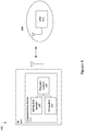
- FIG. 1 schematically illustrates a network environment 100 in accordance with various embodiments.
- the network environment 100 includes a user equipment (UE) 104 wirelessly coupled with a radio access network (RAN) 108.
- the RAN 108 may include an enhanced node base station (eNB) 112 configured to communicate with the UE 104 via an over-the-air (OTA) interface.
- eNB enhanced node base station
- OTA over-the-air
- the RAN 108 may be part of a 3GPP LTE Advanced (LTE-A) network and may be referred to as an evolved universal terrestrial radio access network (EUTRAN). In other embodiments, other radio access network technologies may be utilized.
- LTE-A 3GPP LTE Advanced
- EUTRAN evolved universal terrestrial radio access network
- other radio access network technologies may be utilized.
- the UE 104 may include a communication device 116 that implements various communication protocols in order to effectuate communication with the RAN 108.
- the communication device 116 may be a chip, chipset, or other collection of programmed and/or pre-configured circuitry.
- the communication device 116 may include or be part of baseband circuitry, a radio transceiver circuitry, etc.
- the communication device 116 may include a HARQ-ACK module 120, a channel state information (CSI) module 124, and a transmit module 128 coupled with one another at least as shown.
- CSI channel state information
- the HARQ-ACK module 120 may implement various HARQ processes. For example, in some embodiments, the HARQ-ACK module 120 may determine whether downlink data was correctly received on a Physical Downlink Shared Channel (PDSCH). The HARQ-ACK module 120 may generate HARQ-ACK bit stream, which includes acknowledgement/negative acknowledgement (ACK/NACK) bits, to indicate whether codewords of a downlink transmission were successfully received. In some embodiments, the HARQ-ACK module 120 may generate one ACK/NACK bit for a single codeword downlink transmission and two ACK/NACK bits for a two-codeword downlink transmission. The ACK/NACK bits that correspond to a PDSCH transmission in subframe i-k may be transmitted in subframe i .
- ACK/NACK bits that correspond to a PDSCH transmission in subframe i-k may be transmitted in subframe i .
- the value k may be different in various embodiments and may depend on, for example, a frame structure type, a time division duplex (TDD) uplink/downlink (UL/DL) configuration, etc.
- the value k may be equal to four in some FDD embodiments.
- the HARQ processes may be in accordance with relevant technical specifications, for example, 3GPP Technical Specification (TS) 36.213 V10.6.0 (26 June 2012 ).
- the CSI module 124 may control generation and transmission of various CSI components that relate to channel state.
- the CSI components could include, but are not limited to, channel quality indicator (CQI), precoding matrix indicator (PMI), rank indicator (RI), and precoding type indicator (PTI).
- CQI channel quality indicator
- PMI precoding matrix indicator
- RI rank indicator
- PTI precoding type indicator
- the UE 104 may be semi-statically configured by higher layers to periodically feedback the various CSI components on the PUCCH.
- the CSI feedback may be in accordance with relevant technical specifications, for example, 3GPP TS 36.213.
- the transmit module 128 may be coupled with both the HARQ-ACK module 120 and the CSI module 124.
- the transmit module 128 may receive a HARQ bit stream from the HARQ-ACK module 120 and a CSI bit stream from the CSI module 124.
- a scheduling conflict (or collision) may occur when attempting to encode the HARQ bit stream and the CSI bit stream for transmission. For example, this may occur when the CSI bit stream, which may correspond to a one-cell periodic CSI, is to be transmitted using PUCCH format 2 and the HARQ bit stream, which may correspond to a multi-cell HARQ-ACK, is to be transmitted using PUCCH format 1b with channel selection.
- PUCCH format 2 may be used, for example, to report wideband CQI/PMI and, in some embodiments, may include up to 11 bits.
- the CSI transmitted by PUCCH format 2 can be the final CSI for a certain downlink (DL) cooperative multipoint (CoMP) set and/or for a certain serving cell in a carrier aggregation (CA) scheme.
- DL downlink
- CoMP cooperative multipoint
- CA carrier aggregation
- CA carrier aggregation
- PUCCH format 1b with channel selection may be used so that some of the HARQ-ACK information to be conveyed is indicated by selecting one of a number of possible PUCCH resources.
- PUCCH format 1b with channel selection may be utilized for UEs that support no more than four ACK/NACK bits and are configured with up to two component carriers (CCs) in a CA scheme.
- the payload sizes for HARQ-ACK information using PUCCH format 1b with channel selection may be vary from two to four bits.
- a scheduling conflict may occur when a total number of uplink control information (UCI) bits, which may include both the ACK/NACK bits and the CSI bits, is over 13 bits.
- UCI uplink control information
- the UCI may include up to 15 bits, for example.
- the transmit module 128 may perform various resolution processes in the transmitting of the UCI.
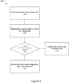
- Figure 2 illustrates a method 200 in accordance with some embodiments.
- Method 200 may be performed by a transmit module of a UE, such as transmit module 128 of UE 104.
- the UE may include and/or have access to one or more computer-readable media having instructions stored thereon, that, when executed, cause the UE, or the transmit module 128, to perform some or all of the method 200.
- A may refer to a number of UCI bits, which may depend on the transmission format;
- a CSI bit stream may be represented by a' 0 , a' 1 , a' 2 , a' 3 , . .., a' A' -1
- a HARQ-ACK bit stream may be represented by a 0 ′′ , a 1 ′′ , ⁇ , a N ⁇ 1 ′′ .
- the method 200 may include detecting a potential scheduling conflict.
- a potential scheduling conflict may occur when the CSI bit stream is to be transmitted using PUCCH format 2 and the HARQ bit stream is to be simultaneously transmitted using PUCCH format 1b with channel selection.
- detection of a potential scheduling conflict may be done when a particular parameter is set. For example, this may be when simultaneousAckNackAndCQI, or an updated paramater such as simultaneousAckNackAndCQI-ChSeI-rX for PUCCH format 1b with channel selection where X is a release-dependent number (e.g., 12), is true.
- the parameter may be set by RRC signaling as described in 3GPP TS 36.331 v9.10.0 (14 March 2012 ), for example.
- the method 200 may include determining a number of UCI bits to be transmitted in a PUCCH transmission of a subframe.
- the UCI bits may include ACK/NACK bits and CSI bits.
- the UCI bits may further include one or more scheduling request (SR) bits.
- SR scheduling request
- the method 200 may include determining whether number of UCI bits is greater than a payload size capable of being conveyed by the PUCCH transmission of a subframe.
- a payload capacity of a PUCCH transmission, having format 2 may be 13 bits, given capabilities of presently-available Reed-Muller (RM) coding.
- the method 200 may include, at 216, jointly coding CSI bits and ACK/NACK bits.
- the CSI and ACK/NACK bits may be multiplexed together and jointly coded for transmission on, for example, a PUCCH format 2 resource.
- FIG. 3 illustrates a transmit module 300 that may be capable of multiplexing the CSI and ACK/NACK bits and jointly coding them on a PUCCH format 2 resource in accordance with some embodiments.
- the transmit module 300 may be similar to and substantially interchangeable with transmit module 128.
- Transmit module 300 may be a time domain structure of PUCCH format 2 for normal cyclical prefix (CP). In other embodiments, other structures may be used.
- CP normal cyclical prefix
- a multiplexer module 304 may multiplex the CSI bit stream with the HARQ-ACK information bit stream to yield a UCI bit stream, a, according to Equation 1.
- a 0 , a 1 , a 2 , a 3 , ... , a A ⁇ 1 a 0 ' , a 1 ' , a 2 ' , a 3 ' , ... , a A ' ⁇ 1 ' , a 0 " , a 1 " , ⁇ , a N ⁇ 1 "
- Equation 1 While the multiplexing of Equation 1 is shown with the HARQ-ACK information bit stream added to the end of the CSI bit stream, other embodiments may use other manners of multiplexing.
- the CSI bit stream may be added to the end of the HARQ-ACK bit stream.
- the CSI bit stream and HARQ-ACK bit stream may be interleaved with one another.
- the SR may also be multiplexed with the CSI and ACK/NACK bits.
- the SR bit may be multiplexed at an end of the ACK/NACK bits.
- an SR bit '1' may represent a positive SR and an SR bit '0' may represent a negative SR.
- the UCI bit stream may be coded, by encoder module 308, using RM coding, tailbiting convolutional coding (TBCC), or some other suitable coding process to provide an encoded bit stream b.
- the UCI bit stream may be coded according to a (20, A ) RM code.
- the code words of the (20, A ) RM code may be a linear combination of the 13 basis sequences denoted M i,n and defined in Table 1.
- PN pseudo-noise
- C-RNTI cell radio network temporary identifier
- the scrambled bits b ⁇ (0),..., b ⁇ (19) may be modulated by modulator module 312.
- the modulator module 314 may employ a quadrature phase shift keying (QPSK) modulation, resulting in a block of complex-valued modulation symbols d (0),..., d (9)
- QPSK quadrature phase shift keying
- bit(s) b (20),..., b ( M bit -1) may be modulated as described in Table 2 resulting in a single modulation symbol d (10) used in the generation of the reference signal (RS) for PUCCH format 2a and 2b as described in section 5.4.2 of 3GPP TS 36.211 v10.5.0.
- the shifted symbols may then be transformed by respective inverse Fast Fourier Transform modules 320 1-9 for transmission on respective PUCCH resource blocks.
- resource blocks 1, 3, 4, 5, and 7 of the first and second slots may be PUCCH resource blocks, while resource blocks 2 and 6 are PUCCH demodulation reference signal (DRS) resource blocks.
- DRS PUCCH demodulation reference signal
- dual RM coding may be used to jointly code the CSI and ACK/NACK bits.
- any RM coding may be used, for example, (32, O) or (20, A ), (20, A ) may be assumed for purposes of discussion.
- a first RM encoder can be used for the channel coding of first UCI and a second RM encoder can be used for the channel coding for a second UCI, where the first UCI may be CSI bits and the second UCI may be ACK/NACK bits or vice versa.
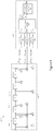
- FIG. 4 illustrates a transmit module 400 in accordance with some embodiments.
- the transmit module 400 may be similar to and substantially interchangeable with transmit module 128.
- the transmit module 400 may be configured to provide dual RM coding for PUCCH format 2.
- the transmit module 400 may include a multiplexer module 404 to multiplex the CSI bit stream with the ACK/NACK bit stream to yield the UCI bit stream similar to that discussed above.
- the transmit module 400 may include a segmenter module 408 to segment the UCI bit stream into two parts. Each segment may be provided to a respective encoder module 412 and 416.
- the encoder modules 412 and 416 may be (20, A ) RM encoders to encode the segmented bit streams.
- the transmit module 400 may further include modulator modules 420 and 424 respectively coupled with the encoder modules 412 and 416.
- the modulator modules 420 and 424 may modulate the encoded bit streams, with QPSK modulation, for example, and provide five QPSK symbols each.
- the transmit module 400 may further include a mapper module 428 coupled with the modulator modules 420 and 424 to receive the QPSK symbols.
- the mapper module 428 may alternatively map the 10 QPSK symbols as d(0) - d(9) for transmission on PUCCH format 2 resources.
- the mapper module 428 may be placed before the modulator modules 420 and 424. Such embodiments may provide a similar alternative mapping operation by mapping two bits from each segment in an alternative manner. Then, QPSK modulation may be applied.
- the joint coding of the CSI and ACK/NACK bits may be done with TBCC.
- a TBCC with constraint length of seven and a mother coding rate of 1/3 may be described below.
- FIG. 5 illustrates an encoder module 500 that may be used in the transmit module 128 in accordance with various embodiments.
- the encoder module 500 may be a mother coding rate 1/3 tail biting convolutional encoder having an encoding section 504 and a rate matching section 508.
- the encoding section 504 may include delay modules 512, serially coupled with one another, of a shift register 514 coupled with adder modules 516 as shown.
- the encoding section output streams, d k 0 , d k 1 and d k 2 may correspond to the first, second, and third parity streams, respectively, as shown in Figure 5 .
- the rate matching section 508 may include sub-block interleaver modules 520, 524, and 528 coupled with the encoding section 504 to respectively receive and subsequently interleave the output streams of the encoding section 504.
- the bits input to the sub-block interleaver modules 520, 524, and 528 may be denoted by d 0 i , d 1 i , d 2 i , ..., d D ⁇ 1 i , where D is the number of bits.
- the rows of the rectangular matrix may be numbered 0, 1, 2, ... R subblock CC ⁇ 1 from top to bottom.
- the intercolumn permuted R subblock CC ⁇ C subblock CC matrix may be equal to: y P 0 y P 1 y P 2 ⁇ y P C subblock CC ⁇ 1 y P 0 ⁇ C subblock CC y P 1 + C subblock CC y P 2 + C subblock CC ⁇ y P C subblock CC ⁇ 1 + C subblock CC ⁇ ⁇ ⁇ ⁇ ⁇ y P 0 + R subblock CC ⁇ 1 ⁇ C subblock CC y P 1 + R subblock CC ⁇ 1 ⁇ C subblock CC y P 2 + R subblock CC ⁇ 1 ⁇ C subblock CC ⁇ y P C subblock CC ⁇ 1 + R subblock CC ⁇ 1 ⁇ C subblock CC ⁇ 1 + R subblock CC ⁇ 1 ⁇ C subblock CC ⁇ 1 ⁇ C subblock CC
- the interleaved streams as shown in Figure 5 , may include v k 0 , v k 1 , and v k 2 respectively provided by sub-block interleaver modules 520, 524, and 528.
- the sub-block interleaver modules 520, 524, and 528 may also be used in interleaving PDCCH modulation symbols.
- the input bit sequence may include PDCCH symbol quadruplets.
- the rate matching section 508 may further include a bit collection module 532 coupled with the sub-block interleaver modules 520, 524, and 528 to receive the interleaved streams and a bit selection and pruning module 536 coupled with the bit collection module 532.
- the bit selection and pruning module 536 may generate the rate matching output bit sequence by the following algorithm.
- the method 200 may include, at 220, discarding CSI bits and coding ACK/NACK bits for transmission using PUCCH format 1b with channel selection. While some embodiments may include discarding ACK/NACK bits instead of CSI bits, typically the ACK/NACK bits are associated with a relatively higher priority and, therefore, will not be discarded.
- CSI bits may be discarded.
- a dropping rule may be implemented in order to provide a relative priority among the CSI bits. For example, CSI may be prioritized according to a PUCCH reporting type associated with the specific CSI information.
- reporting types 3 may be associated with a first priority
- reporting types 2 wideband CQI/PMI
- 2b wideband first PMI
- 2c wideband CQI, first PMI, second PMI
- 4 wideband CQI
- the specific type of CSI is shown in parentheticals.
- the third priority CSI will be dropped before the second priority CSI and the second priority CSI will be dropped before the first priority CSI.
- priority of a cell may decrease as a corresponding serving cell index (for example, ServCellIndex ) increases. That is, the lower the cell index, the higher the priority.
- the coding of the ACK/NACK bits, and any remaining CSI and/or SR bits, may be done using RM coding or TBCC such as the coding shown and described above.
- the ACK/NACK bits may be transmitted on the SR PUCCH resource and CSI can be dropped.
- Figure 6 illustrates a method 600 in accordance with other embodiments.
- Method 600 may be performed by a transmit module of a UE, such as transmit module 128 of UE 104.
- the UE may include and/or have access to one or more computer-readable media having instructions stored thereon, that, when executed, cause the UE, or the transmit module 128, to perform some or all of the method 600.
- the method 600 may include detecting a potential scheduling conflict.
- a potential scheduling conflict may occur when the CSI bit stream is to be transmitted using PUCCH format 2 and the HARQ bit stream is to be transmitted using PUCCH format 1b with channel selection.
- the method 600 may include determining a number of UCI bits to be transmitted in a PUCCH transmission of a subframe.
- the method 600 may include determining whether the number of UCI bits is greater than a payload capacity of the PUCCH transmission of a subframe.
- a payload capacity of a PUCCH format 2 transmission may be 13 bits, given capabilities of presently-available RM coding.
- the method 600 may include, at 616, jointly coding CSI bits and ACK/NACK bits. This may be done similar to that described above with respect to 216 of method 200.
- the method 600 may include, at 620, bundling ACK/NACK bits. In some embodiments, if the number of ACK/NACK bits is more than two, they may be compressed (or bundled) to make the number of ACK/NACK bits no more than two.
- a most significant bit may represent spatial-bundled HARQ-ACK for a primary cell (PCell) and a least significant bit (LSB) may represent spatial-bundled HARQ-ACK for a secondary cell (SCell).
- the bundling may be done by a logical AND operation. For example, an ACK and NACK/discontinuous transmission (DTX) may be mapped to 1 and 0, respectively.
- DTX discontinuous transmission
- the logical AND operation for the bit representation may then be applied as follows:
- four ACK/NACK bits may be compressed to two bundled ACK/NACK bits (one for the PCell and one for the SCell).
- the number of an ACK counter may be used for the bundling operation.
- the UE may detect that at least one downlink assignment has been missed.
- N SPS may be the number of PDSCH transmissions without a corresponding PDCCH within the subframe(s) n-k in serving cell c, where k ⁇ K (0 or 1).
- N cells DL may be the number of configured DL serving cells (with channel selection, this value is 2).
- V DAI , c DL may be the value of the downlink assignment index (DAI) in PDCCH with DCI format 1/1A/1B/1D/2/2A/2B/2C detected by the UE according to Table 5 in subframe n-k m in serving cell c, where k m is the smallest value in the set K , defined in Table 6 such that the UE detects a DCI format 1/1A/1B/1D/2/2A/2B/2C as defined in 3GPP TS 36.213.
- DCI downlink assignment index
- U DAI , c may be the total number of PDCCH(s) with assigned PDSCH transmission(s) and PDCCH indicating downlink SPS release detected by the UE within the subframe(s) n-k in serving cell c, where k ⁇ K.
- the method 600 may include, at 624, transmitting the bundled ACK/NACK bits and the CSI bits.
- the bundled HARQ-ACK may be transmitted either by phase modulation on a second reference signal (RS) using PUCCH format 2 or by joint coding of the CSI and the bundled HARQ-ACK using PUCCH format 2.
- the joint coding may be TBCC, RM coding, or dual RM coding, similar to that described above
- the phase modulation process may be used for normal CP case and the joint coding process, for example TBCC, may be used for extended CP since the number of RS symbols in a slot for extended CP is one that is not available for RS modulation.
- This embodiment may be described in further detail below with respect to Figure 8 .
- the SR may be treated as a part of the ACK/NACK bits. If an SR bit is not part of the UCI and a scheduling request is positive, then the bundled HARQ-ACK may be transmitted on an SR resource.
- phase modulation may be applied as follows.
- the bits b (20),..., b ( M bit -1) may be modulated as described in Table 7 resulting in a single modulation symbol d(10) used in the generation of the reference signal for PUCCH format 2a and 2b. Since the above-bundled HARQ-ACK bits may be two, M bit may be 22. That is, b(20) and b(21) may be bundled HARQ-ACK bits.
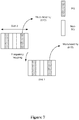
- Figure 7 illustrates phase modulation using PUCCH format 2b in accordance with some embodiments.
- the second RS of each slot may be modulated by d(10) to transmit the bundled HARQ-ACK.
- a hybrid scheme may be used, while joint coding is used for extended CP.
- a hybrid scheme may involve a first operation in which HARQ-ACK mapped states are developed using, for example, time-domain compression. This may result in four bundled ACK/NACK bits, b 0 , b 1 , b 2 , and b 3 .
- a first set of the bundled ACK/NACK bits for example, two bits, b 0 and b 1 , may be jointly coded with CSI bits, while a second set of the bundled ACK/NACK bits, for example, the remaining two bits, b 2 and b 3 , may be separately coded.
- the encode first set may be moduled on a non-referency symbol, while the second encoded set may modulated with an RS symbol in a second slot of PUCCH format 2.
- the above methods 200 and 600 respectively describe that, when a number of UCI bits is greater than a payload capacity of a PUCCH format 2 transmission, for example, the CSI bits may be dropped or the ACK/NACK bits may be bundeled.
- the UCI bits may be jointly coded using TBCC, which in some embodiments may be capable of increasing payload capacity to 15 or even 20 bits.
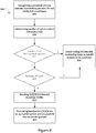
- Figure 8 illustrates a method 800 in accordance with another embodiment.
- Method 200 may be performed by a transmit module of a UE, such as transmit module 128 of UE 104.
- the UE may include and/or have access to one or more computer-readable media having instructions stored thereon, that, when executed, cause the UE, or the transmit module 128, to perform some or all of the method 200.
- the method 800 may include, at 804, recognizing a potential collision between transmitting periodic CSI and HARQ-ACK in a subframe. In some embodiments, this may be similar to determining a potential scheduling conflict as discussed above.
- the method 800 may include determining a number of UCI bits to be transmitted.
- the method 800 may include determining whether a number of UCI bits is greater than a payload capacity of a subframe using PUCCH format 2, for example.
- the method 800 may include, at 816, jointly coding the UCI bits, using TBCC, for example, and modulating them on non-reference symbols of the subframe.
- Other embodiments described herein may similarly modulate the jointly coded UCI bits on the non-reference symbols of the subframe.
- the method 800 may include, at 820, determining whether an extended CP is used.
- the method 800 may loop back to jointly coding the UCI bits and modulating them on non-reference symbols of the subframe at 816.
- the method may include, at 824, bundling ACK/NACK bits and encoding CSI bits.
- the method 800 may include, at 828, modulating bundled ACK/NACK bits on second reference symbol of the subframe and encoded CSI bits on non-reference symbols.
- the HARQ-ACK codebook size may be determined by a radio resource control (RRC) configuration level such as the number of configured serving cells and configured transmission modes.
- RRC radio resource control
- the CSI reporting may be done for the activated cells only by a media access control (MAC) control element (CE).
- MAC media access control
- the change by the MAC CE is more frequent than by RRC.
- the CSI reporting in a transient period by activation/deactivation may be ignored by the eNB since the information may not be available until the eNB knows the UE successfully receives the MAC CE.
- multiplexing of CSI and HARQ-ACK may refer to jointly encoding CSI and ACK/NACK bits, for example.
- the payload size may be a predetermined value, for example, 13 bits, that corresponds to the payload capacity of PUCCH format 2. Any remaining information bits, other than CSI and ACK/NACK bits, may be padded by a predetermined bit or bit pattern, for example, all '0'. An eNB may decode the PUCCH based on the predetermined value. Thus, even if the eNB assumes a wrong CSI payload size, the HARQ-ACK information can survive.
- a concatenation may be performed according to a predefined order to ensure the reliability of the HARQ-ACK information.
- the CSI bits may be appended at an end of a sequence of concatenated ACK/NACK bits.
- the multiplexed CSI may always be for the PCell. In particular, this may be done for the CC activation/deactivation ambiguity period. As the PCell will not be deactivated, there will be no ambiguity. If the subframe in which the CSI and HARQ-ACK is to be transmitted is not for CSI reporting for the PCell, the payload for CSI may be reserved, zero-padded, or predetermined value-padded. Alternatively, if the subframe in which the CSI and HARQ-ACK is to be transmitted is not for CSI reporting for the PCell, the CSI content may be dropped and the HARQ-ACK information may be transmitted by PUCCH format 1b with channel selection.
- the jointly-coded CSI may be for a serving cell that is predetermined or RRC-configured. In particular, this may be useful during the CC activation/deactivation ambiguity period. If the subframe in which the CSI and HARQ-ACK is to be transmitted is not for CSI reporting for the configured (or predetermined) SCell, the payload for CSI may be reserved, zero-padded, or predetermined value-padded.
- the CSI content may be dropped and the HARQ-ACK information may be transmitted by PUCCH format 1b with channel selection.
- the multiplexing of CSI and HARQ-ACK may be done only when the CSI reporting is to be done for the predetermined serving cell(s). In particular, this may be useful during the CC activation/deactivation ambiguity period.
- the predetermined serving cells may be predetermined by a technical specification, primary cell (or cell with the lowest cell index), or RRC-configured cell(s).
- the CSI may be dropped and the HARQ-ACK may be done by PUCCH format 1b with channel selection, or other multiplexing methods may be used, for example, phase modulation for bundled ACK/NACK on the second RS in a slot or joint coding of CSI and bundled ACK/NACK.
- Figure 9 illustrates multiplexing of UCI on PUSCH (for normal CP) in accordance with some embodiments.
- Figure 9 illustrates resource blocks of a subframe.
- the RBs may include one or more single-carrier (SC) frequency division multiple access (FDMA) symbols over one or more virtual sub-carriers (discrete Fourier transform (DFT) input).
- SC single-carrier
- FDMA frequency division multiple access
- DFT discrete Fourier transform
- the CSI and/or ACK/NACK bits may be piggybacked on PUSCH together with the UL-SCH.
- the periodic CSI and the HARQ-ACK may be piggybacked on PUSCH as seen in Figure 9 .
- the piggybacked HARQ-ACK may be either original HARQ-ACK for PUCCH format 1b with channel selection or bundled HARQ-ACK depending on the use case.
- individual ACK/NACK bits as in PUCCH format 3 may be piggybacked on PUSCH.
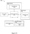
- FIG. 10 illustrates, for one embodiment, an example system 1000 comprising one or more processor(s) 1004, system control logic 1008 coupled with at least one of the processor(s) 1004, system memory 1012 coupled with system control logic 1008, non-volatile memory (NVM)/storage 1016 coupled with system control logic 1008, a network interface 1020 coupled with system control logic 1008, and input/output (I/O) devices 1032 coupled with system control logic 1008.
- processor(s) 1004 coupled with at least one of the processor(s) 1004, system memory 1012 coupled with system control logic 1008, non-volatile memory (NVM)/storage 1016 coupled with system control logic 1008, a network interface 1020 coupled with system control logic 1008, and input/output (I/O) devices 1032 coupled with system control logic 1008.
- I/O input/output
- the processor(s) 1004 may include one or more single-core or multi-core processors.
- the processor(s) 1004 may include any combination of general-purpose processors and dedicated processors (e.g., graphics processors, application processors, baseband processors, etc.).
- System control logic 1008 may include any suitable interface controllers to provide for any suitable interface to at least one of the processor(s) 1004 and/or to any suitable device or component in communication with system control logic 1008.
- System control logic 1008 for one embodiment may include one or more memory controller(s) to provide an interface to system memory 1012.
- System memory 1012 may be used to load and store data and/or instructions, e.g., feedback logic 1024.
- System memory 1012 for one embodiment may include any suitable volatile memory, such as suitable dynamic random access memory (DRAM), for example.
- DRAM dynamic random access memory
- NVM/storage 1016 may include one or more tangible, non-transitory computer-readable media used to store data and/or instructions, e.g., feedback logic 1024.
- NVM/storage 1016 may include any suitable non-volatile memory, such as flash memory, for example, and/or may include any suitable non-volatile storage device(s), such as one or more hard disk drive(s) (HDD(s)), one or more compact disk (CD) drive(s), and/or one or more digital versatile disk (DVD) drive(s), for example.
- HDD hard disk drive
- CD compact disk
- DVD digital versatile disk
- the NVM/storage 1016 may include a storage resource physically part of a device on which the system 1000 is installed or it may be accessible by, but not necessarily a part of, the device.
- the NVM/storage 1016 may be accessed over a network via the network interface 1020 and/or over Input/Output (I/O) devices 1032.
- I/O Input/Output
- the feedback logic 1024 may include instructions that, when executed by one or more of the processors 1004, cause the system 1000 to perform feedback of UCI as described with respect to the above embodiments.
- the feedback logic 1024 may include hardware, software, and/or firmware components that may or may not be explicitly shown in system 1000.
- Network interface 1020 may have a transceiver 1022 to provide a radio interface for system 1000 to communicate over one or more network(s) and/or with any other suitable device.
- the transceiver 1022 may be integrated with other components of system 1000.
- the transceiver 1022 may include a processor of the processor(s) 1004, memory of the system memory 1012, and NVM/Storage of NVM/Storage 1016.
- Network interface 1020 may include any suitable hardware and/or firmware.
- Network interface 1020 may include a plurality of antennas to provide a multiple input, multiple output radio interface.
- Network interface 1020 for one embodiment may include, for example, a wired network adapter, a wireless network adapter, a telephone modem, and/or a wireless modem.
- At least one of the processor(s) 1004 may be packaged together with logic for one or more controller(s) of system control logic 1008.
- at least one of the processor(s) 1004 may be packaged together with logic for one or more controllers of system control logic 1008 to form a System in Package (SiP).
- SiP System in Package
- at least one of the processor(s) 1004 may be integrated on the same die with logic for one or more controller(s) of system control logic 1008.
- at least one of the processor(s) 1004 may be integrated on the same die with logic for one or more controller(s) of system control logic 1008 to form a System on Chip (SoC).
- SoC System on Chip
- the I/O devices 1032 may include user interfaces designed to enable user interaction with the system 1000, peripheral component interfaces designed to enable peripheral component interaction with the system 1000, and/or sensors designed to determine environmental conditions and/or location information related to the system 1000.
- the user interfaces could include, but are not limited to, a display (e.g., a liquid crystal display, a touch screen display, etc.), speakers, a microphone, one or more cameras (e.g., a still camera and/or a video camera), a flashlight (e.g., a light emitting diode flash), and a keyboard.
- a display e.g., a liquid crystal display, a touch screen display, etc.
- speakers e.g., a microphone
- one or more cameras e.g., a still camera and/or a video camera
- a flashlight e.g., a light emitting diode flash
- the peripheral component interfaces may include, but are not limited to, a non-volatile memory port, a universal serial bus (USB) port, an audio jack, and a power supply interface.
- a non-volatile memory port may include, but are not limited to, a non-volatile memory port, a universal serial bus (USB) port, an audio jack, and a power supply interface.
- USB universal serial bus
- the sensors may include, but are not limited to, a gyro sensor, an accelerometer, a proximity sensor, an ambient light sensor, and a positioning unit.
- the positioning unit may also be part of, or interact with, the network interface 1020 to communicate with components of a positioning network, e.g., a global positioning system (GPS) satellite.
- GPS global positioning system
- system 1000 may be a mobile computing device such as, but not limited to, a laptop computing device, a tablet computing device, a netbook, a smartphone, etc. In various embodiments, system 1000 may have more or less components, and/or different architectures.
Description
- Embodiments of the present invention relate generally to the field of wireless communications, and more particularly, to multiplexing channel state information and hybrid automatic repeat request - acknowledgement information.
- In
Release 10 of the 3rd Generation Partnership Project (3GPP) Long Term Evolution - Advanced (LTE-A) standard, a conflict may occur when a user equipment is configured for carrier aggregation and the timing for multi-cell hybrid automatic repeat request - acknowledgement (HARQ-ACK) transmission using by a physical uplink control channel (PUCCH) format 1 b with channel selection and for CSI usingPUCCH format 2 is overlapped in the same subframe. In such an event, the UE drops the CSI and transmits the HARQ-ACK information using PUCCH format 1 b with channel selection. However, the frequent dropping of the CSI due to collision between the CSI and the HARQ-ACK information may result in downlink throughput loss due to the unavailability of proper CSI feedback. - QUALCOMM INCORPORATED: "On reducing periodic CSI dropping for CA operation", 3GPP DRAFT; R1-122762 ON REDUCING PERIODIC CSI DROPPING FOR CA OPERATION, 3RD GENERATION PARTNERSHIP PROJECT (3GPP), MOBILE COMPETENCE CENTRE; 650, ROUTE DES LUCIOLES; F-06921 SOPHIA-ANTIPOLIS CEDEX; FRANCE, vol. RAN WG1, no. Prague, Czech Republic; 12 May 2012, discloses utilization of the PUCCH
format 3 to convey CSI feedback with and without ACK/NACK/SR including multiplexing, prioritization, encoding and power control. -
WO2011157098 discloses a method for transmitting information on a physical uplink control channel (PUCCH) including the following steps: a user equipment (UE) selects information from channel state information (CSI) to transmit (S1); the information selected from the CSI is transmitted on the PUCCH with one or both of hybrid automatic retransmission acknowledgment information and a scheduling request (S2), which enables a base station to obtain not only the information in the CSI but also one or both of the hybrid automatic retransmission acknowledgment information and the scheduling request from the PUCCH. - ZTE: "Remaining Issues of UL Channel Combinations for Rel-10", 3GPP DRAFT; Rl-110808, 3RD GENERATION PARTNERSHIP PROJECT (3GPP), MOBILE COMPETENCE CENTRE; 650, ROUTE DES LUCIOLES; F-06921 SOPHIA-ANTIPOLIS CEDEX; FRANCE, vol. RAN WG1, no. Taipei, Taiwan; 15 February 2011, discloses multiplexing of periodic CSI/SR and ACK/NACK under the scenario of carrier aggregation.
-
WO2012057571 discloses a method for transmitting uplink control information in the event a plurality of cells are constructed, which comprises the following steps: receiving a PDCCH and/or a PDSCH; generating acknowledgement information on the PDCCH and/or PDSCH; and, if acknowledgement information transmission timing and channel state information transmission timing collide with each other, dropping the channel state information and transmitting only the acknowledgement information, or transmitting the acknowledgement information and the channel state information together in accordance with a predetermined condition. - Embodiments will be readily understood by the following detailed description in conjunction with the accompanying drawings. To facilitate this description, like reference numerals designate like structural elements.
- Embodiments are illustrated by way of example and not by way of limitation in the figures of the accompanying drawings.
-
Figure 1 schematically illustrates a network environment in accordance with various embodiments. -
Figure 2 illustrates a method of transmitting uplink control information (UCI) in accordance with various embodiments. -
Figure 3 schematically illustrates a transmit module in accordance with various embodiments. -
Figure 4 schematically illustrates a transmit module in accordance with various embodiments. -
Figure 5 schematically illustrates an encoder module in accordance with various embodiments. -
Figure 6 illustrates a method of transmitting uplink control information (UCI) in accordance with various embodiments. -
Figure 7 illustrates phase modulation concepts in accordance with various embodiments. -
Figure 8 illustrates a method of transmitting UCI in accordance with various embodiments. -
Figure 9 illustrates multiplexing of UCI on PUSCH in accordance with various embodiments. -
Figure 10 schematically depicts an example system in accordance with various embodiments. - Illustrative embodiments of the present disclosure include, but are not limited to, methods, systems, computer-readable media, and apparatuses for multiplexing channel state information (CSI) and hybrid automatic repeat request - acknowledgement (HARQ-ACK) information. Embodiments described may enhance downlink throughput while reducing a dropping loss of CSI or HARQ-ACK information.
- Various aspects of the illustrative embodiments will be described using terms commonly employed by those skilled in the art to convey the substance of their work to others skilled in the art. However, it will be apparent to those skilled in the art that alternate embodiments may be practiced with only some of the described aspects. For purposes of explanation, specific numbers, materials, and configurations are set forth in order to provide a thorough understanding of the illustrative embodiments. However, it will be apparent to one skilled in the art that alternate embodiments may be practiced without the specific details. In other instances, well-known features are omitted or simplified in order not to obscure the illustrative embodiments.
- Further, various operations will be described as multiple discrete operations, in turn, in a manner that is most helpful in understanding the illustrative embodiments; however, the order of description should not be construed as to imply that these operations are necessarily order dependent. In particular, these operations need not be performed in the order of presentation.
- The phrase "in some embodiments" is used repeatedly. The phrase generally does not refer to the same embodiments; however, it may. The terms "comprising," "having," and "including" are synonymous, unless the context dictates otherwise.
- The phrase "A and/or B" means (A), (B), or (A and B). The phrases "A/B" and "A or B" mean (A), (B), or (A and B), similar to the phrase "A and/or B."
- As used herein, the term "module" refers to, is part of, or includes hardware components such as an Application Specific Integrated Circuit (ASIC), an electronic circuit, a logic circuit, a processor (shared, dedicated, or group) and/or memory (shared, dedicated, or group) that are configured to provide the described functionality. In some embodiments, the module may execute one or more software or firmware programs to provide at least some of the described functionality.
-
Figure 1 schematically illustrates anetwork environment 100 in accordance with various embodiments. Thenetwork environment 100 includes a user equipment (UE) 104 wirelessly coupled with a radio access network (RAN) 108. The RAN 108 may include an enhanced node base station (eNB) 112 configured to communicate with the UE 104 via an over-the-air (OTA) interface. The RAN 108 may be part of a 3GPP LTE Advanced (LTE-A) network and may be referred to as an evolved universal terrestrial radio access network (EUTRAN). In other embodiments, other radio access network technologies may be utilized. - The UE 104 may include a
communication device 116 that implements various communication protocols in order to effectuate communication with the RAN 108. Thecommunication device 116 may be a chip, chipset, or other collection of programmed and/or pre-configured circuitry. In some embodiments, thecommunication device 116 may include or be part of baseband circuitry, a radio transceiver circuitry, etc. - The
communication device 116 may include a HARQ-ACK module 120, a channel state information (CSI)module 124, and atransmit module 128 coupled with one another at least as shown. - The HARQ-
ACK module 120 may implement various HARQ processes. For example, in some embodiments, the HARQ-ACK module 120 may determine whether downlink data was correctly received on a Physical Downlink Shared Channel (PDSCH). The HARQ-ACK module 120 may generate HARQ-ACK bit stream, which includes acknowledgement/negative acknowledgement (ACK/NACK) bits, to indicate whether codewords of a downlink transmission were successfully received. In some embodiments, the HARQ-ACK module 120 may generate one ACK/NACK bit for a single codeword downlink transmission and two ACK/NACK bits for a two-codeword downlink transmission. The ACK/NACK bits that correspond to a PDSCH transmission in subframe i-k may be transmitted in subframe i. The value k may be different in various embodiments and may depend on, for example, a frame structure type, a time division duplex (TDD) uplink/downlink (UL/DL) configuration, etc. The value k may be equal to four in some FDD embodiments. In some embodiments, the HARQ processes may be in accordance with relevant technical specifications, for example, 3GPP Technical Specification (TS) 36.213 V10.6.0 (26 June 2012). - The CSI
module 124 may control generation and transmission of various CSI components that relate to channel state. The CSI components could include, but are not limited to, channel quality indicator (CQI), precoding matrix indicator (PMI), rank indicator (RI), and precoding type indicator (PTI). In some embodiments, the UE 104 may be semi-statically configured by higher layers to periodically feedback the various CSI components on the PUCCH. In some embodiments, the CSI feedback may be in accordance with relevant technical specifications, for example, 3GPP TS 36.213. - The transmit
module 128 may be coupled with both the HARQ-ACK module 120 and theCSI module 124. The transmitmodule 128 may receive a HARQ bit stream from the HARQ-ACK module 120 and a CSI bit stream from theCSI module 124. In some embodiments, a scheduling conflict (or collision) may occur when attempting to encode the HARQ bit stream and the CSI bit stream for transmission. For example, this may occur when the CSI bit stream, which may correspond to a one-cell periodic CSI, is to be transmitted usingPUCCH format 2 and the HARQ bit stream, which may correspond to a multi-cell HARQ-ACK, is to be transmitted using PUCCH format 1b with channel selection. -
PUCCH format 2 may be used, for example, to report wideband CQI/PMI and, in some embodiments, may include up to 11 bits. The CSI transmitted byPUCCH format 2 can be the final CSI for a certain downlink (DL) cooperative multipoint (CoMP) set and/or for a certain serving cell in a carrier aggregation (CA) scheme. Hereafter, the CA case may be assumed for convenience; however, similar concepts may be equally applicable for DL CoMP CSI feedback, which may require a greater number of CSI bits than a single cell operation. - PUCCH format 1b with channel selection may be used so that some of the HARQ-ACK information to be conveyed is indicated by selecting one of a number of possible PUCCH resources. PUCCH format 1b with channel selection may be utilized for UEs that support no more than four ACK/NACK bits and are configured with up to two component carriers (CCs) in a CA scheme. The payload sizes for HARQ-ACK information using PUCCH format 1b with channel selection may be vary from two to four bits.
- If a transmission resource, for example,
PUCCH format 2, that is to be used for both the CSI and the HARQ-ACK has a payload size of up to, for example, 13 bits, then a scheduling conflict may occur when a total number of uplink control information (UCI) bits, which may include both the ACK/NACK bits and the CSI bits, is over 13 bits. With up to 11 bits for the CSI and up to 4 bits for the HARQ-ACK, the UCI may include up to 15 bits, for example. - Upon detecting a potential scheduling conflict, the transmit
module 128 may perform various resolution processes in the transmitting of the UCI. -
Figure 2 illustrates amethod 200 in accordance with some embodiments.Method 200 may be performed by a transmit module of a UE, such as transmitmodule 128 ofUE 104. In some embodiments, the UE may include and/or have access to one or more computer-readable media having instructions stored thereon, that, when executed, cause the UE, or the transmitmodule 128, to perform some or all of themethod 200. - For purposes of the present discussion, A may refer to a number of UCI bits, which may depend on the transmission format; A' may refer to a number of CSI bits (for example, A'= 4, 5, ... 11), C may refer to a maximum payload size that may be conveyed by PUCCH format 2 (for example, C=11 or 13), N may refer to a number of ACK/NACK bits for channel selection (for example, N= 2, 3, or 4), a CSI bit stream may be represented by a' 0,a' 1,a' 2,a' 3,...,a' A'-1, and a HARQ-ACK bit stream may be represented by


- At 204, the
method 200 may include detecting a potential scheduling conflict. As mentioned above, a potential scheduling conflict may occur when the CSI bit stream is to be transmitted usingPUCCH format 2 and the HARQ bit stream is to be simultaneously transmitted using PUCCH format 1b with channel selection. In some embodiments, detection of a potential scheduling conflict may be done when a particular parameter is set. For example, this may be when simultaneousAckNackAndCQI, or an updated paramater such as simultaneousAckNackAndCQI-ChSeI-rX for PUCCH format 1b with channel selection where X is a release-dependent number (e.g., 12), is true. In some embodiments, the parameter may be set by RRC signaling as described in 3GPP TS 36.331 v9.10.0 (14 March 2012), for example. - At 208, the
method 200 may include determining a number of UCI bits to be transmitted in a PUCCH transmission of a subframe. As mentioned above, the UCI bits may include ACK/NACK bits and CSI bits. In some embodiments, the UCI bits may further include one or more scheduling request (SR) bits. - At 212, the
method 200 may include determining whether number of UCI bits is greater than a payload size capable of being conveyed by the PUCCH transmission of a subframe. In various embodiments, a payload capacity of a PUCCH transmission, havingformat 2, may be 13 bits, given capabilities of presently-available Reed-Muller (RM) coding. - If it is determined that the number of UCI bits to be transmitted is not greater than the payload size, then the
method 200 may include, at 216, jointly coding CSI bits and ACK/NACK bits. The CSI and ACK/NACK bits may be multiplexed together and jointly coded for transmission on, for example, aPUCCH format 2 resource. -
Figure 3 illustrates a transmitmodule 300 that may be capable of multiplexing the CSI and ACK/NACK bits and jointly coding them on aPUCCH format 2 resource in accordance with some embodiments. The transmitmodule 300 may be similar to and substantially interchangeable with transmitmodule 128. Transmitmodule 300 may be a time domain structure ofPUCCH format 2 for normal cyclical prefix (CP). In other embodiments, other structures may be used. - A
multiplexer module 304 may multiplex the CSI bit stream with the HARQ-ACK information bit stream to yield a UCI bit stream, a, according toEquation 1.
- While the multiplexing of
Equation 1 is shown with the HARQ-ACK information bit stream added to the end of the CSI bit stream, other embodiments may use other manners of multiplexing. For example, in another embodiment, the CSI bit stream may be added to the end of the HARQ-ACK bit stream. In still another embodiment, the CSI bit stream and HARQ-ACK bit stream may be interleaved with one another. - If SR is to be transmitted in the same subframe without an uplink shared channel (UL-SCH), the SR may also be multiplexed with the CSI and ACK/NACK bits. In some embodiments, the SR bit may be multiplexed at an end of the ACK/NACK bits. In some embodiments, an SR bit '1' may represent a positive SR and an SR bit '0' may represent a negative SR.
- The UCI bit stream may be coded, by
encoder module 308, using RM coding, tailbiting convolutional coding (TBCC), or some other suitable coding process to provide an encoded bit stream b. In some embodiments, the UCI bit stream may be coded according to a (20, A) RM code. The code words of the (20, A) RM code may be a linear combination of the 13 basis sequences denoted Mi,n and defined in Table 1.Table 1 - Basis sequences for (20, A) code i Mi,0 Mi,1 Mi,2 Mi,3 Mi,4 Mi,5 Mi,6 Mi,7 Mi,8 Mi,9 Mi,10 Mi, 11 Mi, 12 0 1 1 0 0 0 0 0 0 0 0 1 1 0 1 1 1 1 0 0 0 0 0 0 1 1 1 0 2 1 0 0 1 0 0 1 0 1 1 1 1 1 3 1 0 1 1 0 0 0 0 1 0 1 1 1 4 1 1 1 1 0 0 0 1 0 0 1 1 1 5 1 1 0 0 1 0 1 1 1 0 1 1 1 6 1 0 1 0 1 0 1 0 1 1 1 1 1 7 1 0 0 1 1 0 0 1 1 0 1 1 1 8 1 1 0 1 1 0 0 1 0 1 1 1 1 9 1 0 1 1 1 0 1 0 0 1 1 1 1 10 1 0 1 0 0 1 1 1 0 1 1 1 1 11 1 1 1 0 0 1 1 0 1 0 1 1 1 12 1 0 0 1 0 1 0 1 1 1 1 1 1 13 1 1 0 1 0 1 0 1 0 1 1 1 1 14 1 0 0 0 1 1 0 1 0 0 1 0 1 15 1 1 0 0 1 1 1 1 0 1 1 0 1 16 1 1 1 0 1 1 1 0 0 1 0 1 1 17 1 0 0 1 1 1 0 0 1 0 0 1 1 18 1 1 0 1 1 1 1 1 0 0 0 0 0 19 1 0 0 0 0 1 1 0 0 0 0 0 0 - The bits of the encoded bit stream may be denoted by b 0,b 1,b 2,b 3,...,b B-1 where B=20 and with

- The encoded bit stream may be scrambled, by
scrambler module 312, with a UE-specific scrambling sequence to provide a scrambled bit stream having scrambled bits b̃(0),...,b̃(19) according to
encoder module 308, may be initialized with
- The scrambled bits b̃(0),...,b̃(19) may be modulated by
modulator module 312. In some embodiments, themodulator module 314 may employ a quadrature phase shift keying (QPSK) modulation, resulting in a block of complex-valued modulation symbols d(0),...,d(9) - Each complex-valued symbol d(0),...,d(9) may be multiplied, by multiplier modules 3161-9, with a cyclically shifted length


- Resources used for transmission of PUCCH formats 2/2a/2b may be identified by a resource
index 


- For PUCCH formats 2a and 2b, supported for normal cyclic prefix only, the bit(s) b(20),...,b(M bit -1) may be modulated as described in Table 2 resulting in a single modulation symbol d(10) used in the generation of the reference signal (RS) for PUCCH format 2a and 2b as described in section 5.4.2 of 3GPP TS 36.211 v10.5.0.
Table 2 PUCCH format b(20),...,b(M bit -1) d(10) 2a 0 1 1 -1 2b 00 1 01 -j 10 j 11 -1 - The shifted symbols may then be transformed by respective inverse Fast Fourier Transform modules 3201-9 for transmission on respective PUCCH resource blocks. As can be seen in
Figure 3 , resource blocks 1, 3, 4, 5, and 7 of the first and second slots may be PUCCH resource blocks, while resource blocks 2 and 6 are PUCCH demodulation reference signal (DRS) resource blocks. - In another embodiment, dual RM coding may be used to jointly code the CSI and ACK/NACK bits. Although any RM coding may be used, for example, (32, O) or (20, A), (20, A) may be assumed for purposes of discussion.
- In another embodiment using dual RM coding, a first RM encoder can be used for the channel coding of first UCI and a second RM encoder can be used for the channel coding for a second UCI, where the first UCI may be CSI bits and the second UCI may be ACK/NACK bits or vice versa.
-
Figure 4 illustrates a transmitmodule 400 in accordance with some embodiments. The transmitmodule 400 may be similar to and substantially interchangeable with transmitmodule 128. The transmitmodule 400 may be configured to provide dual RM coding forPUCCH format 2. - The transmit
module 400 may include amultiplexer module 404 to multiplex the CSI bit stream with the ACK/NACK bit stream to yield the UCI bit stream similar to that discussed above. - The transmit
module 400 may include asegmenter module 408 to segment the UCI bit stream into two parts. Each segment may be provided to arespective encoder module encoder modules - The transmit
module 400 may further includemodulator modules encoder modules modulator modules - The transmit
module 400 may further include amapper module 428 coupled with themodulator modules mapper module 428 may alternatively map the 10 QPSK symbols as d(0) - d(9) for transmission onPUCCH format 2 resources. - In some embodiments, the
mapper module 428 may be placed before themodulator modules - In some embodiments, the joint coding of the CSI and ACK/NACK bits may be done with TBCC. A TBCC with constraint length of seven and a mother coding rate of 1/3 may be described below.
-
Figure 5 illustrates anencoder module 500 that may be used in the transmitmodule 128 in accordance with various embodiments. Theencoder module 500 may be amother coding rate 1/3 tail biting convolutional encoder having anencoding section 504 and arate matching section 508. - The
encoding section 504 may includedelay modules 512, serially coupled with one another, of ashift register 514 coupled withadder modules 516 as shown. An initial value of theshift register 514 of theencoding section 504 may be set to values corresponding to the last six information bits of an input stream, which may be the UCI bit stream, so that the initial and final stages of theshift register 514, corresponding to outputs of the first andlast delay modules 512, respectively, are the same. Therefore, denoting theshift register 514 of theencoding section 504 by s 0,s 1,s 2,...,s 5, then the initial value of the shift register may be set to si = c (K-1-i) . - The encoding section output streams,


Figure 5 . - The
rate matching section 508 may includesub-block interleaver modules encoding section 504 to respectively receive and subsequently interleave the output streams of theencoding section 504. - The bits input to the
sub-block interleaver modules 


First, assign

Second, determine a number of rows of the matrix


Third, if


column 0 or row 0:
Fourth, perform inter-column permutation for the matrix based on the pattern
Table 3 - Inter-column permutation for sub-block interleaver module Number of columns Inter-column permutation pattern 

32 < 1, 17, 9, 25, 5, 21, 13, 29, 3, 19, 11, 27, 7, 23, 15, 31, 0, 16, 8, 24, 4, 20, 12, 28, 2, 18, 10, 26, 6, 22, 14, 30 > 

Fifth, the output of thesub-block interleaver modules 


Figure 5 , may include


sub-block interleaver modules - The
sub-block interleaver modules - The
rate matching section 508 may further include abit collection module 532 coupled with thesub-block interleaver modules bit collection module 532. - The
bit collection module 532 may provide a virtual circular buffer to provide a bit-collection bit stream having a length of Kw = 3K Π that is generated as follows:


- The rate matching output bit sequence may be ek , k=0, 1, ..., E-1, wherein E denotes the rate matching output sequence length. The bit selection and pruning module 536 may generate the rate matching output bit sequence by the following algorithm.

- Referring again to
Figure 2 , if it is determined, at 212, that the number of UCI bits to be transmitted is greater than the payload capacity, then themethod 200 may include, at 220, discarding CSI bits and coding ACK/NACK bits for transmission using PUCCH format 1b with channel selection. While some embodiments may include discarding ACK/NACK bits instead of CSI bits, typically the ACK/NACK bits are associated with a relatively higher priority and, therefore, will not be discarded. - In some embodiments, only some of the CSI bits may be discarded. In such cases, a dropping rule may be implemented in order to provide a relative priority among the CSI bits. For example, CSI may be prioritized according to a PUCCH reporting type associated with the specific CSI information. For example, reporting types 3 (RI), 5 (RI/first PMI), 6 (RI/PTI), and 2a (wideband first PMI), may be associated with a first priority; reporting types 2 (wideband CQI/PMI), 2b (wideband first PMI), 2c (wideband CQI, first PMI, second PMI), and 4 (wideband CQI) may be associated with a second priority; and reporting types 1 (sub-band CQI) and 1a (sub-band CQI/second PMI) may be associated with a third priority. The specific type of CSI is shown in parentheticals. Thus, the third priority CSI will be dropped before the second priority CSI and the second priority CSI will be dropped before the first priority CSI. Among reporting types with the same priority, priority of a cell may decrease as a corresponding serving cell index (for example, ServCellIndex) increases. That is, the lower the cell index, the higher the priority.
- The coding of the ACK/NACK bits, and any remaining CSI and/or SR bits, may be done using RM coding or TBCC such as the coding shown and described above.
- In some embodiments, if the number of UCI bits includes an SR bit and is greater than the payload size and if SR is positive, the ACK/NACK bits may be transmitted on the SR PUCCH resource and CSI can be dropped.
-
Figure 6 illustrates amethod 600 in accordance with other embodiments.Method 600 may be performed by a transmit module of a UE, such as transmitmodule 128 ofUE 104. In some embodiments, the UE may include and/or have access to one or more computer-readable media having instructions stored thereon, that, when executed, cause the UE, or the transmitmodule 128, to perform some or all of themethod 600. - At 604, the
method 600 may include detecting a potential scheduling conflict. As mentioned above, a potential scheduling conflict may occur when the CSI bit stream is to be transmitted usingPUCCH format 2 and the HARQ bit stream is to be transmitted using PUCCH format 1b with channel selection. - At 608, the
method 600 may include determining a number of UCI bits to be transmitted in a PUCCH transmission of a subframe. - At 612, the
method 600 may include determining whether the number of UCI bits is greater than a payload capacity of the PUCCH transmission of a subframe. In various embodiments, a payload capacity of aPUCCH format 2 transmission may be 13 bits, given capabilities of presently-available RM coding. - If it is determined that the number of UCI bits to be transmitted is not greater than the payload capacity, then the
method 600 may include, at 616, jointly coding CSI bits and ACK/NACK bits. This may be done similar to that described above with respect to 216 ofmethod 200. - If it is determined, at 612, that the number of UCI bits to be transmitted is greater than the payload capacity, then the
method 600 may include, at 620, bundling ACK/NACK bits. In some embodiments, if the number of ACK/NACK bits is more than two, they may be compressed (or bundled) to make the number of ACK/NACK bits no more than two. - If transmit module is configured for frequency division duplexing (FDD), spatial bundling per serving cell may be applied. A most significant bit (MSB) may represent spatial-bundled HARQ-ACK for a primary cell (PCell) and a least significant bit (LSB) may represent spatial-bundled HARQ-ACK for a secondary cell (SCell). The bundling may be done by a logical AND operation. For example, an ACK and NACK/discontinuous transmission (DTX) may be mapped to 1 and 0, respectively. The logical AND operation for the bit representation may then be applied as follows:
- ACK, ACK → bundled HARQ-ACK is ACK;
- ACK, NACK/DTX → bundled HARQ-ACK is NACK;
- NACK/DTX, ACK → bundled HARQ-ACK is NACK; and
- NACK/DTX, NACK/DTX → bundled HARQ-ACK is NACK.
- Thus, four ACK/NACK bits (two for the PCell and two for the SCell) may be compressed to two bundled ACK/NACK bits (one for the PCell and one for the SCell).
- While the above bundling describes use of a logical AND operation, other embodiments may use other logical operations, such as a logical OR operation.
- If transmit module is configured for time division duplexing (TDD), the number of an ACK counter may be used for the bundling operation. The value of b(0), b(1) may be generated according to Table 4 from


Table 4 - Mapping between multiple HARQ-ACK responses and b(0), b(1) Number of ACK among multiple 
b(0),b(1) 0 or None (UE detect at least one DL assignment is missed) 0, 0 1 1, 1 2 1, 0 3 0, 1 4 1, 1 5 1, 0 6 0, 1 7 1, 1 8 1, 0 9 0, 1 NSPS may be the number of PDSCH transmissions without a corresponding PDCCH within the subframe(s) n-k in serving cell c, where k∈K (0 or 1).


DCI format 1/1A/1B/1D/2/2A/2B/2C detected by the UE according to Table 5 in subframe n-km in serving cell c, where km is the smallest value in the set K, defined in Table 6 such that the UE detects aDCI format 1/1A/1B/1D/2/2A/2B/2C as defined in 3GPP TS 36.213.DAI MSB, LSB 
Number of subframes with PDSCH transmission and with PDCCH/EPDCCH indicating DL SPS release 0,0 1 1 or 5 or 9 0,1 2 2 or 6 1,0 3 3 or 7 1,1 4 0 or 4 or 8 Table 5 - Value of Downlink Assignment Index Table 6- Downlink association set index K: for {k 0,k 1,···k M-1} TDD UL/DL Configuration Subframe n 0 1 2 3 4 5 6 7 8 9 0 - - 6 - 4 - - 6 - 4 1 - - 7, 6 4 - - - 7, 6 4 - 2 - - 8, 7, 4, 6 - - - - 8, 7, 4, 6 - - 3 - - 7, 6, 11 6, 5 5, 4 - - - - - 4 - - 12, 8, 7, 11 6, 5, 4, 7 - - - - - - 5 - - 13, 12, 9, 8, 7, 5, 4, 11, 6 - - - - - - - 6 - - 7 7 5 - - 7 7 - - U DAI,c may be the total number of PDCCH(s) with assigned PDSCH transmission(s) and PDCCH indicating downlink SPS release detected by the UE within the subframe(s) n-k in serving cell c, where k∈K.
- Referring again to
Figure 6 , upon bundling the ACK/NACK bits at 620, themethod 600 may include, at 624, transmitting the bundled ACK/NACK bits and the CSI bits. The bundled HARQ-ACK may be transmitted either by phase modulation on a second reference signal (RS) usingPUCCH format 2 or by joint coding of the CSI and the bundled HARQ-ACK usingPUCCH format 2. The joint coding may be TBCC, RM coding, or dual RM coding, similar to that described above - In another embodiment, the phase modulation process may be used for normal CP case and the joint coding process, for example TBCC, may be used for extended CP since the number of RS symbols in a slot for extended CP is one that is not available for RS modulation. This embodiment may be described in further detail below with respect to
Figure 8 . If SR is also part of the UCI, then the SR may be treated as a part of the ACK/NACK bits. If an SR bit is not part of the UCI and a scheduling request is positive, then the bundled HARQ-ACK may be transmitted on an SR resource. - In some embodiments, phase modulation may be applied as follows. For PUCCH formats 2a and 2b, supported for normal cyclic prefix only, the bits b(20),...,b(M bit -1) may be modulated as described in Table 7 resulting in a single modulation symbol d(10) used in the generation of the reference signal for PUCCH format 2a and 2b. Since the above-bundled HARQ-ACK bits may be two, Mbit may be 22. That is, b(20) and b(21) may be bundled HARQ-ACK bits.
Table 7 - Modulation symbol d(10) for PUCCH formats 2a and 2b PUCCH format b(20),...,b(M bit -1) d(10) 2a 0 1 1 -1 2b 00 1 01 -j 10 j 11 -1 -
Figure 7 illustrates phase modulation using PUCCH format 2b in accordance with some embodiments. As can be seen inFigure 7 , the second RS of each slot may be modulated by d(10) to transmit the bundled HARQ-ACK. - In still another embodiment, for normal CP, a hybrid scheme may be used, while joint coding is used for extended CP. A hybrid scheme may involve a first operation in which HARQ-ACK mapped states are developed using, for example, time-domain compression. This may result in four bundled ACK/NACK bits, b0, b1, b2, and b3 . A first set of the bundled ACK/NACK bits, for example, two bits, b0 and b1 , may be jointly coded with CSI bits, while a second set of the bundled ACK/NACK bits, for example, the remaining two bits, b2 and b3 , may be separately coded. The encode first set may be moduled on a non-referency symbol, while the second encoded set may modulated with an RS symbol in a second slot of
PUCCH format 2. - The
above methods PUCCH format 2 transmission, for example, the CSI bits may be dropped or the ACK/NACK bits may be bundeled. However, in other embodiments, the UCI bits may be jointly coded using TBCC, which in some embodiments may be capable of increasing payload capacity to 15 or even 20 bits. -
Figure 8 illustrates amethod 800 in accordance with another embodiment.Method 200 may be performed by a transmit module of a UE, such as transmitmodule 128 ofUE 104. In some embodiments, the UE may include and/or have access to one or more computer-readable media having instructions stored thereon, that, when executed, cause the UE, or the transmitmodule 128, to perform some or all of themethod 200. - The
method 800 may include, at 804, recognizing a potential collision between transmitting periodic CSI and HARQ-ACK in a subframe. In some embodiments, this may be similar to determining a potential scheduling conflict as discussed above. - At 808, the
method 800 may include determining a number of UCI bits to be transmitted. - At 812, the
method 800 may include determining whether a number of UCI bits is greater than a payload capacity of a subframe usingPUCCH format 2, for example. - If, at 812, it is determined that the number of UCI bits is not greater than the payload capacity, then the
method 800 may include, at 816, jointly coding the UCI bits, using TBCC, for example, and modulating them on non-reference symbols of the subframe. Other embodiments described herein may similarly modulate the jointly coded UCI bits on the non-reference symbols of the subframe. - If, at 812, it is determined that the number of UCI bits is greater than the payload capacity, then the
method 800 may include, at 820, determining whether an extended CP is used. - If, at 820, it is determined that an extended CP is used, then the
method 800 may loop back to jointly coding the UCI bits and modulating them on non-reference symbols of the subframe at 816. - If, at 820, it is determined that an extended CP is not used (for example, a normal CP is used), then the method may include, at 824, bundling ACK/NACK bits and encoding CSI bits.
- Following 824, the
method 800 may include, at 828, modulating bundled ACK/NACK bits on second reference symbol of the subframe and encoded CSI bits on non-reference symbols. - In a general HARQ-ACK procedure, the HARQ-ACK codebook size may be determined by a radio resource control (RRC) configuration level such as the number of configured serving cells and configured transmission modes. On the other hand, the CSI reporting may be done for the activated cells only by a media access control (MAC) control element (CE). In general, the change by the MAC CE is more frequent than by RRC. In Rel-10 of 3GPP LTE-A, the CSI reporting in a transient period by activation/deactivation may be ignored by the eNB since the information may not be available until the eNB knows the UE successfully receives the MAC CE. However, with joint coding of HARQ-ACK and CSI, the contents may not be easily ignored because the HARQ-ACK may not be ignored due to its importance. These situations may be handled as follows. As used below, "multiplexing of CSI and HARQ-ACK" may refer to jointly encoding CSI and ACK/NACK bits, for example.
- In some embodiments, in case of multiplexing of CSI and HARQ-ACK information, the payload size may be a predetermined value, for example, 13 bits, that corresponds to the payload capacity of
PUCCH format 2. Any remaining information bits, other than CSI and ACK/NACK bits, may be padded by a predetermined bit or bit pattern, for example, all '0'. An eNB may decode the PUCCH based on the predetermined value. Thus, even if the eNB assumes a wrong CSI payload size, the HARQ-ACK information can survive. - In some embodiments, in case of multiplexing of CSI and HARQ-ACK, a concatenation may be performed according to a predefined order to ensure the reliability of the HARQ-ACK information. In such embodiments, the CSI bits may be appended at an end of a sequence of concatenated ACK/NACK bits.
- In some embodiments, in case of multiplexing of CSI and HARQ-ACK, the multiplexed CSI may always be for the PCell. In particular, this may be done for the CC activation/deactivation ambiguity period. As the PCell will not be deactivated, there will be no ambiguity. If the subframe in which the CSI and HARQ-ACK is to be transmitted is not for CSI reporting for the PCell, the payload for CSI may be reserved, zero-padded, or predetermined value-padded. Alternatively, if the subframe in which the CSI and HARQ-ACK is to be transmitted is not for CSI reporting for the PCell, the CSI content may be dropped and the HARQ-ACK information may be transmitted by PUCCH format 1b with channel selection.
- In some embodiments, in case of multiplexing of CSI and HARQ-ACK, the jointly-coded CSI may be for a serving cell that is predetermined or RRC-configured. In particular, this may be useful during the CC activation/deactivation ambiguity period. If the subframe in which the CSI and HARQ-ACK is to be transmitted is not for CSI reporting for the configured (or predetermined) SCell, the payload for CSI may be reserved, zero-padded, or predetermined value-padded. Alternatively, if the subframe in which the CSI and HARQ-ACK is to be transmitted is not for CSI reporting for the configured (or predetermined) SCell, the CSI content may be dropped and the HARQ-ACK information may be transmitted by PUCCH format 1b with channel selection.
- In some embodiments, the multiplexing of CSI and HARQ-ACK may be done only when the CSI reporting is to be done for the predetermined serving cell(s). In particular, this may be useful during the CC activation/deactivation ambiguity period. The predetermined serving cells may be predetermined by a technical specification, primary cell (or cell with the lowest cell index), or RRC-configured cell(s). When CSI reporting is not to be done for the predetermined serving cell(s), the CSI may be dropped and the HARQ-ACK may be done by PUCCH format 1b with channel selection, or other multiplexing methods may be used, for example, phase modulation for bundled ACK/NACK on the second RS in a slot or joint coding of CSI and bundled ACK/NACK.
-
Figure 9 illustrates multiplexing of UCI on PUSCH (for normal CP) in accordance with some embodiments.Figure 9 illustrates resource blocks of a subframe. The RBs may include one or more single-carrier (SC) frequency division multiple access (FDMA) symbols over one or more virtual sub-carriers (discrete Fourier transform (DFT) input). - If a UE is not configured by simultaneous transmission of PUSCH and PUCCH and if PUSCH is transmitted on the subframe that is also transmitted by PUCCH that contains periodic CSI and/or ACK/NACK bits, the CSI and/or ACK/NACK bits may be piggybacked on PUSCH together with the UL-SCH.
- The periodic CSI and the HARQ-ACK may be piggybacked on PUSCH as seen in
Figure 9 . The piggybacked HARQ-ACK may be either original HARQ-ACK for PUCCH format 1b with channel selection or bundled HARQ-ACK depending on the use case. Alternatively, individual ACK/NACK bits as inPUCCH format 3 may be piggybacked on PUSCH. - The
UE 104 described herein may be implemented into a system using any suitable hardware and/or software to configure as desired.Figure 10 illustrates, for one embodiment, anexample system 1000 comprising one or more processor(s) 1004,system control logic 1008 coupled with at least one of the processor(s) 1004,system memory 1012 coupled withsystem control logic 1008, non-volatile memory (NVM)/storage 1016 coupled withsystem control logic 1008, anetwork interface 1020 coupled withsystem control logic 1008, and input/output (I/O)devices 1032 coupled withsystem control logic 1008. - The processor(s) 1004 may include one or more single-core or multi-core processors. The processor(s) 1004 may include any combination of general-purpose processors and dedicated processors (e.g., graphics processors, application processors, baseband processors, etc.).
-
System control logic 1008 for one embodiment may include any suitable interface controllers to provide for any suitable interface to at least one of the processor(s) 1004 and/or to any suitable device or component in communication withsystem control logic 1008. -
System control logic 1008 for one embodiment may include one or more memory controller(s) to provide an interface tosystem memory 1012.System memory 1012 may be used to load and store data and/or instructions, e.g.,feedback logic 1024.System memory 1012 for one embodiment may include any suitable volatile memory, such as suitable dynamic random access memory (DRAM), for example. - NVM/
storage 1016 may include one or more tangible, non-transitory computer-readable media used to store data and/or instructions, e.g.,feedback logic 1024. NVM/storage 1016 may include any suitable non-volatile memory, such as flash memory, for example, and/or may include any suitable non-volatile storage device(s), such as one or more hard disk drive(s) (HDD(s)), one or more compact disk (CD) drive(s), and/or one or more digital versatile disk (DVD) drive(s), for example. - The NVM/
storage 1016 may include a storage resource physically part of a device on which thesystem 1000 is installed or it may be accessible by, but not necessarily a part of, the device. For example, the NVM/storage 1016 may be accessed over a network via thenetwork interface 1020 and/or over Input/Output (I/O)devices 1032. - The
feedback logic 1024 may include instructions that, when executed by one or more of theprocessors 1004, cause thesystem 1000 to perform feedback of UCI as described with respect to the above embodiments. In various embodiments, thefeedback logic 1024 may include hardware, software, and/or firmware components that may or may not be explicitly shown insystem 1000. -
Network interface 1020 may have atransceiver 1022 to provide a radio interface forsystem 1000 to communicate over one or more network(s) and/or with any other suitable device. In various embodiments, thetransceiver 1022 may be integrated with other components ofsystem 1000. For example, thetransceiver 1022 may include a processor of the processor(s) 1004, memory of thesystem memory 1012, and NVM/Storage of NVM/Storage 1016.Network interface 1020 may include any suitable hardware and/or firmware.Network interface 1020 may include a plurality of antennas to provide a multiple input, multiple output radio interface.Network interface 1020 for one embodiment may include, for example, a wired network adapter, a wireless network adapter, a telephone modem, and/or a wireless modem. - For one embodiment, at least one of the processor(s) 1004 may be packaged together with logic for one or more controller(s) of
system control logic 1008. For one embodiment, at least one of the processor(s) 1004 may be packaged together with logic for one or more controllers ofsystem control logic 1008 to form a System in Package (SiP). For one embodiment, at least one of the processor(s) 1004 may be integrated on the same die with logic for one or more controller(s) ofsystem control logic 1008. For one embodiment, at least one of the processor(s) 1004 may be integrated on the same die with logic for one or more controller(s) ofsystem control logic 1008 to form a System on Chip (SoC). - In various embodiments, the I/
O devices 1032 may include user interfaces designed to enable user interaction with thesystem 1000, peripheral component interfaces designed to enable peripheral component interaction with thesystem 1000, and/or sensors designed to determine environmental conditions and/or location information related to thesystem 1000. - In various embodiments, the user interfaces could include, but are not limited to, a display (e.g., a liquid crystal display, a touch screen display, etc.), speakers, a microphone, one or more cameras (e.g., a still camera and/or a video camera), a flashlight (e.g., a light emitting diode flash), and a keyboard.
- In various embodiments, the peripheral component interfaces may include, but are not limited to, a non-volatile memory port, a universal serial bus (USB) port, an audio jack, and a power supply interface.
- In various embodiments, the sensors may include, but are not limited to, a gyro sensor, an accelerometer, a proximity sensor, an ambient light sensor, and a positioning unit. The positioning unit may also be part of, or interact with, the
network interface 1020 to communicate with components of a positioning network, e.g., a global positioning system (GPS) satellite. - In various embodiments, the
system 1000 may be a mobile computing device such as, but not limited to, a laptop computing device, a tablet computing device, a netbook, a smartphone, etc. In various embodiments,system 1000 may have more or less components, and/or different architectures. - Although certain embodiments have been illustrated and described herein for purposes of description, a wide variety of alternate and/or equivalent embodiments or implementations calculated to achieve the same purposes may be substituted for the embodiments shown and described without departing from the scope of the present disclosure. This application is intended to cover any adaptations or variations of the embodiments discussed herein. Therefore, it is manifestly intended that embodiments described herein be limited only by the claims and the equivalents thereof.
- Some non-limiting examples are provide below.
- Example 1 includes an apparatus for transmitting uplink control information comprising: a hybrid automatic repeat request - acknowledgement (HARQ-ACK) module to generate a HARQ-ACK bit stream to indicate whether downlink data was successfully received on a physical downlink shared channel (PDSCH); a channel state indicator module (CSI) to generate a CSI bit stream that relates to a channel state; and a transmit module coupled with the HARQ-ACK module to receive the HARQ-ACK bit stream and further coupled with the CSI module to receive the CSI bit stream, the transmit module to: jointly code the HARQ-ACK bit stream and the CSI bit stream on a physical uplink control channel (PUCCH) transmission if the number of uplink control information (UCI) bits, which include bits of the HARQ-ACK bit stream and the CSI bit stream, to be transmitted is not greater than a payload capacity of the PUCCH transmission; and discard at least some bits of the CSI bit stream or bundle at least some of the bits of the HARQ-ACK bit stream if the number of UCI bits is greater than the payload capacity.
- Example 2 includes the apparatus of
example claim 1, wherein if the number of the UCI bits is less than or equal to the payload capacity, the transmit module is to jointly code the bits of the HARQ-ACK bit stream and the CSI bit stream with a Reed-Muller (RM) code. - Example 3 includes the apparatus of example 2, wherein the RM code is a dual RM code.
- Example 4 includes the apparatus of example 3, wherein the transmit module further comprises: a first RM encoder module to code a first segment of a UCI bit stream; and a second RM encoder module to code a second segment of the UCI bit stream.
- Example 5 includes the apparatus of example 4, wherein the first segment is bits of the CSI bit stream and the second segment is bits of the HARQ-ACK bit stream.
- Example 6 includes the apparatus of example 1, wherein the number of the UCI bits is less than or equal to the payload capacity and the transmit module is to jointly code the bits of the HARQ-ACK bit stream and the CSI bit stream with a tailbiting convolutional code (TBCC).
- Example 7 includes the apparatus of example 1, wherein the PUCCH transmission is a
PUCCH Format 2 transmission. - Example 8 includes the apparatus of any of examples 1-7, wherein the UCI bits includes a scheduling request (SR) bit that indicates a positive SR, the number of UCI bits is greater than the payload capacity, and the transmit module is further to: transmit bits of the HARQ-ACK bit stream on an SR PUCCH and drop the bits of the CSI bit stream.
- Example 9 includes anapparatus for transmitting uplink control information comprising: a hybrid automatic repeat request - acknowledgement (HARQ-ACK) module to generate a HARQ-ACK bit stream to indicate whether downlink data was successfully received on a physical downlink shared channel (PDSCH); a channel state indicator module (CSI) to generate a CSI bit stream that relates to a channel state; and
a transmit module coupled with the HARQ-ACK module to receive the HARQ-ACK bit stream and further coupled with the CSI module to receive the CSI bit stream, the transmit module to:- detect a potential scheduling conflict between a hybrid automatic repeat request - acknowledgement (HARQ-ACK) transmission using channel selection and a channel state information (CSI) transmission; andjointly code, based on detection of a potential scheduling conflict CSI bits of the CSI transmission and ACK/NACK bits of the HARQ-ACK transmission, on a physical uplink control channel (PUCCH) of a subframe with a tailbiting convolutional code (TBCC).
- Example 10 includes the apparatus of example 9, wherein the PUCCH transmission is a
PUCCH Format 2 transmission. - Example 11 includes the apparatus of example 9, wherein the transmit module comprises: an encoder section to generate a plurality of output streams based on the CSI bit stream and the HARQ-ACK bit stream; and a rate matcher coupled with the encoding section to receive the plurality of output streams and to generate a serial output bit sequence based on the plurality of output streams.
- Example 12 includes the apparatus of example 11, wherein the encoding section comprises: a plurality of delay elements serially coupled with one another; and a plurality of adder elements coupled with the plurality of delay elements.
- Example 13 includes the apparatus of example 11, wherein the rate matcher comprises: a plurality of sub-block interleaver modules to respectively receive the plurality of output streams from the encoder section and to provide a respective plurality of interleaved streams; a bit collection module coupled with the plurality of sub-block interleaver modules to receive the plurality of interleaved streams, to provide a virtual circular buffer to output a bit-collection bit stream; and a bit selection and pruning module coupled with the bit collection module to receive the bit-collection bit stream and provide a rate-matched output bit sequence.
- Example 14 includes the apparatus of any of examples 9-13, wherein the TBCC has a constraint length of seven and a mother coding rate of 1/3.
- Example 15 includes a method for transmitting uplink control information comprising: recognizing a potential collision between transmitting periodic channel state information (CSI) and transmitting hybrid automatic repeat request - acknowledgement (HARQ-ACK) in a subframe; determining a number of uplink control information (UCI) bits, which includes CSI bits of the CSI transmission and ACK/NACK bits of the HARQ-ACK transmission, to be transmitted in the subframe using a physical uplink control channel (PUCCH); if a normal cyclic prefix is used, modulating bundled ACK/NACK bits on a second reference signal (RS) symbol of the subframe and modulating, after channel coding, encoded CSI bits on non-RS symbols; and if an extended cyclic prefix is used, jointly coding the CSI bits and the ACK/NACK bits and modulating the jointly encoded CSI bits and ACK/NACK bits on non-RS symbols of the subframe.
- Example 16 includes the method of example 15, wherein if a normal cyclic prefix is used, the method further comprises: bundling the ACK/NACK bits.
- Example 17 includes the method of example 16, wherein a transmit module is configured for frequency division duplexing and the bundling of the ACK/NACK bits comprises: spatially bundling the ACK/NACK bits by having a most significant bit represent spatially-bundled HARQ-ACK for a primary cell and a least significant bit represent spatially-bundled HARQ-ACK for a secondary cell.
- Example 18 includes the method of example 17, wherein the spatial bundling is based on a logical AND operation.
- Example 19 includes the method of example 16, wherein a transmit module is configured for time division duplexing and the bundling of the ACK/NACK bits comprises: using a number of an ACK counter that tracks a number of ACKs among multiple HARQ-ACK responses to generate the bundled ACK/NACK bits.
- Example 20 includes a system for wireless communications comprising: user interfaces that include a display, a speaker, and a microphone; and a communication device coupled with the user interfaces to transmit and receive data over a wireless network, the communication device including: a hybrid automatic repeat request - acknowledgement (HARQ-ACK) module to generate a HARQ-ACK bit stream to indicate whether downlink data was
successfully received on a physical downlink shared channel (PDSCH); a channel state indicator module (CSI) to generate a CSI bit stream that relates to a channel state; and a transmit module coupled with the HARQ-ACK module to receive the HARQ-ACK bit stream and further coupled with the CSI module to receive the CSI bit stream, the transmit module to: if an extended cyclic prefix is used, jointly code bits of the HARQ-ACK bit stream and bits of the CSI bit stream; and if a normal cyclic prefix is used, jointly code a first set of bits of the HARQ-ACK bit stream with bits of the CSI bit stream and separately code a second set of bits of the HARQ-ACK bit stream. - Example 21 includes the system of example 20, wherein, if a normal cyclic prefix is used, the transmit module is further to: modulate jointly encoded first set of bits of the HARQ-ACK bit stream and bits of the CSI bit stream on a non-reference signal (RS) symbol of a subframe; and modulate the seperately coded second set of bits of the HARQ-ACK bit stream on a RS symbol of the subframe.
- Example 22 includes the system of example 21, wherein the reference signal symbol is in a second slot of the subframe.
- Example 23 includes the system of example 20, wherein the transmit module is to jointly code the bits of the HARQ-ACK bit stream and bits of the CSI bit stream with a dual RM code.
- Example 24 includes the system of example 20, wherein the transmit module is to jointly code the bits of the HARQ-ACK bit stream and the bits of the CSI bit stream with a tailbiting convolutional code (TBCC).
- Example 25 includes the system of any of examples 20 - 24, wherein transmit module is to transmit the HARQ-ACK bit stream and the CSI bit stream on a physical uplink control channel (PUCCH)
Format 2 transmission. - Example 26 includes an apparatus for transmitting uplink control information comprising: means for recognizing a potential collision between transmitting periodic channel state information (CSI) and transmitting hybrid automatic repeat request - acknowledgement (HARQ-ACK) in a subframe; means for determining a number of uplink control information (UCI) bits, which includes CSI bits of the CSI transmission and ACK/NACK bits of the HARQ-ACK transmission, to be transmitted in the subframe using a physical uplink control channel (PUCCH); if a normal cyclic prefix is used, means for modulating bundled ACK/NACK bits on a second reference signal (RS) symbol of the subframe and modulating, after channel coding, encoded CSI bits on non-RS symbols; and if an extended cyclic prefix is used, means for jointly coding the CSI bits and the ACK/NACK bits and modulating the jointly encoded CSI bits and ACK/NACK bits on non-RS symbols of the subframe.
- Example 27 includes the apparatus of example 26, further comprising: means for bundling the ACK/NACK bits if a normal cyclic prefix is used.
- Example 28 includes the apparatus of example 27, wherein the apparatus is configured for frequency division duplexing and further comprises: means for spatially bundling the ACK/NACK bits by having a most significant bit represent spatially-bundled HARQ-ACK for a primary cell and a least significant bit represent spatially-bundled HARQ-ACK for a secondary cell.
- Example 29 includes the apparatus of example 28, wherein the spatial bundling is based on a logical AND operation.
- Example 30 includes the apparatus of example 27, wherein the apparatus is configured for time division duplexing and further comprises: means for using a number of an ACK counter that tracks a number of ACKs among multiple HARQ-ACK responses to generate the bundled ACK/NACK bits.
- Example 31 includes one or more computer readable media having instructions that, when executed, cause a communication device to jointly code bits of an hybrid automatic repeat request - acknowledgement (HARQ-ACK) bit stream and bits of a channel state information (CSI) bit stream if an extended cyclic prefix is used; and jointly code a first set of bits of the HARQ-ACK bit stream with bits of the CSI bit stream and separately code a second set of bits of the HARQ-ACK bit stream if a normal cyclic prefix is used.
- Example 32 includes the one or more computer readable media of example 31, wherein, if a normal cyclic prefix is used, the instructions further cause the device to: modulate jointly encoded first set of bits of the HARQ-ACK bit stream and bits of the CSI bit stream on a non-reference signal (RS) symbol of a subframe; and modulate the seperately coded second set of bits of the HARQ-ACK bit stream on a RS symbol of the subframe.
- Example 33 includes the one or more computer-readable media of example 32, wherein the reference signal symbol is in a second slot of the subframe.
- Example 34 includes an apparatus for transmitting uplink control information comprising: means for generating a HARQ-ACK bit stream to indicate whether downlink data was successfully received on a physical downlink shared channel (PDSCH); means for generating a CSI bit stream that relates to a channel state; and means for detecting a potential scheduling conflict between a hybrid automatic repeat request - acknowledgement (HARQ-ACK) transmission using channel selection and a channel state information (CSI) transmission; and jointly coding, based on detection of a potential scheduling conflict CSI bits of the CSI transmission and ACK/NACK bits of the HARQ-ACK transmission, on a physical uplink control channel (PUCCH) of a subframe with a tailbiting convolutional code (TBCC).
Claims (11)
- A method comprising:generating a hybrid automatic repeat request - acknowledgement (HARQ-ACK) bit stream to indicate whether downlink data was successfully received on a physical downlink shared channel (PDSCH);generating a channel state indicator (CSI) bit stream that relates to a channel state;if an extended cyclic prefix is used, jointly coding bits of the HARQ-ACK bit stream and bits of the CSI bit stream with a dual Reed-Muller code or a tailbiting convolutional code (TBCC); the method being characterised in that if a normal cyclic prefix is used, jointly coding a first set of bits of the HARQ-ACK bit stream with bits of the CSI bit stream and separately coding a second set of bits of the HARQ-ACK bit stream.
- The method of claim 1, wherein, if a normal cyclic prefix is used, the method further comprises:modulating jointly encoded first set of bits of the HARQ-ACK bit stream and bits of the CSI bit stream on a non-reference signal (RS) symbol of a subframe; andmodulating the separately coded second set of bits of the HARQ-ACK bit stream on a RS symbol of the subframe.
- The method of claim 2, wherein the reference signal symbol is in a second slot of the subframe.
- The method of any of claims 1-3, wherein the HARQ-ACK bit stream and the CSI bit stream are to be transmitted on a physical uplink control channel (PUCCH) Format 2 transmission.
- A system for wireless communications comprising:user interfaces that include a display, a speaker, and a microphone; anda communication device coupled with the user interfaces to transmit and receive data over a wireless network, the communication device including:a hybrid automatic repeat request - acknowledgement (HARQ-ACK) module to generate a HARQ-ACK bit stream to indicate whether downlink data was successfully received on a physical downlink shared channel (PDSCH);a channel state indicator module (CSI) to generate a CSI bit stream that relates to a channel state; anda transmit module coupled with the HARQ-ACK module to receive the HARQ-ACK bit stream and further coupled with the CSI module to receive the CSI bit stream, the transmit module to:if an extended cyclic prefix is used, jointly code bits of the HARQ-ACK bit stream and bits of the CSI bit stream with a dual RM code or a tailbiting convolutional code (TBCC); andif a normal cyclic prefix is used, jointly code a first set of bits of the HARQ-ACK bit stream with bits of the CSI bit stream and separately code a second set of bits of the HARQ-ACK bit stream.
- The system of claim 5, wherein, if a normal cyclic prefix is used, the transmit module is further to:modulate jointly encoded first set of bits of the HARQ-ACK bit stream and bits of the CSI bit stream on a non-reference signal (RS) symbol of a subframe; andmodulate the seperately coded second set of bits of the HARQ-ACK bit stream on a RS symbol of the subframe.
- The system of claim 6, wherein the reference signal symbol is in a second slot of the subframe.
- The system of any of claims 5-7, wherein transmit module is to transmit the HARQ-ACK bit stream and the CSI bit stream on a physical uplink control channel (PUCCH) Format 2 transmission.
- One or more computer readable media having instructions that, when executed, cause a communication device to:jointly code bits of an hybrid automatic repeat request - acknowledgement (HARQ-ACK) bit stream and bits of a channel state information (CSI) bit stream if an extended cyclic prefix is used; andjointly code a first set of bits of the HARQ-ACK bit stream with bits of the CSI bit stream and separately code a second set of bits of the HARQ-ACK bit stream if a normal cyclic prefix is used.
- The one or more computer readable media of claim 9, wherein, if a normal cyclic prefix is used, the instructions further cause the device to:modulate jointly encoded first set of bits of the HARQ-ACK bit stream and bits of the CSI bit stream on a non-reference signal (RS) symbol of a subframe; andmodulate the seperately coded second set of bits of the HARQ-ACK bit stream on a RS symbol of the subframe.
- The one or more computer-readable media of claim 10, wherein the reference signal symbol is in a second slot of the subframe.
Priority Applications (1)
| Application Number | Priority Date | Filing Date | Title |
|---|---|---|---|
| EP18151568.5A EP3328142A1 (en) | 2012-08-03 | 2013-08-05 | Multiplexing of channel state information and hybrid automatic repeat request - acknowledgement information |
Applications Claiming Priority (3)
| Application Number | Priority Date | Filing Date | Title |
|---|---|---|---|
| US201261679627P | 2012-08-03 | 2012-08-03 | |
| US13/934,095 US9294230B2 (en) | 2012-07-02 | 2013-07-02 | Multiplexing of channel state information and hybrid automatic repeat request—acknowledgement information |
| PCT/US2013/053659 WO2014022861A1 (en) | 2012-08-03 | 2013-08-05 | Multiplexing of channel state information and hybrid automatic repeat request - acknowledgement information |
Related Child Applications (2)
| Application Number | Title | Priority Date | Filing Date |
|---|---|---|---|
| EP18151568.5A Division-Into EP3328142A1 (en) | 2012-08-03 | 2013-08-05 | Multiplexing of channel state information and hybrid automatic repeat request - acknowledgement information |
| EP18151568.5A Division EP3328142A1 (en) | 2012-08-03 | 2013-08-05 | Multiplexing of channel state information and hybrid automatic repeat request - acknowledgement information |
Publications (3)
| Publication Number | Publication Date |
|---|---|
| EP2880802A1 EP2880802A1 (en) | 2015-06-10 |
| EP2880802A4 EP2880802A4 (en) | 2016-05-11 |
| EP2880802B1 true EP2880802B1 (en) | 2018-03-28 |
Family
ID=74555376
Family Applications (2)
| Application Number | Title | Priority Date | Filing Date |
|---|---|---|---|
| EP13825921.3A Not-in-force EP2880802B1 (en) | 2012-08-03 | 2013-08-05 | Multiplexing of channel state information and hybrid automatic repeat request - acknowledgement information |
| EP18151568.5A Withdrawn EP3328142A1 (en) | 2012-08-03 | 2013-08-05 | Multiplexing of channel state information and hybrid automatic repeat request - acknowledgement information |
Family Applications After (1)
| Application Number | Title | Priority Date | Filing Date |
|---|---|---|---|
| EP18151568.5A Withdrawn EP3328142A1 (en) | 2012-08-03 | 2013-08-05 | Multiplexing of channel state information and hybrid automatic repeat request - acknowledgement information |
Country Status (6)
| Country | Link |
|---|---|
| EP (2) | EP2880802B1 (en) |
| CN (3) | CN108155977B (en) |
| ES (1) | ES2669271T3 (en) |
| HK (2) | HK1249809A1 (en) |
| HU (1) | HUE037722T2 (en) |
| WO (1) | WO2014022861A1 (en) |
Families Citing this family (17)
| Publication number | Priority date | Publication date | Assignee | Title |
|---|---|---|---|---|
| WO2016163855A1 (en) * | 2015-04-09 | 2016-10-13 | Samsung Electronics Co., Ltd. | Method for multiplexing uplink information |
| US10491337B2 (en) | 2015-08-12 | 2019-11-26 | Lg Electronics Inc. | Method for transmitting ACK/NACK in wireless communication system and apparatus using same |
| US11115158B2 (en) * | 2016-05-13 | 2021-09-07 | Lenovo Innovations Limited (Hong Kong) | Data acknowledgement in a wireless communication system |
| WO2017218749A1 (en) * | 2016-06-15 | 2017-12-21 | Intel IP Corporation | Channel state and beam related information reporting |
| CN110463102B (en) * | 2017-03-24 | 2022-06-21 | 瑞典爱立信有限公司 | Method, apparatus, and medium for HARQ-ACK feedback |
| CN106941371B (en) * | 2017-04-19 | 2019-12-24 | 西安电子科技大学 | Reliable transmission method for on-demand files of satellite measurement and control network |
| US11038652B2 (en) * | 2017-06-09 | 2021-06-15 | Apple Inc. | Concurrent transmission of acknowledgment and scheduling request information on a control channel |
| DK3646500T3 (en) * | 2017-06-28 | 2022-03-07 | Ericsson Telefon Ab L M | Operating a user device and a receiving radio node based on a HARQ codebook, configured by a configuring radio node |
| WO2019082247A1 (en) * | 2017-10-23 | 2019-05-02 | 株式会社Nttドコモ | User terminal and radio communication method |
| CN108259154B (en) * | 2018-01-12 | 2022-05-24 | 中兴通讯股份有限公司 | Information transmission method, information reception method, information transmission device, information reception device, storage medium, and electronic device |
| WO2019192007A1 (en) | 2018-04-05 | 2019-10-10 | Qualcomm Incorporated | Collision handling for csi reporting on pusch |
| CN110380833A (en) * | 2018-04-13 | 2019-10-25 | 维沃移动通信有限公司 | PUCCH resource determines method, terminal and the network equipment |
| CN111106903B (en) * | 2018-10-26 | 2021-06-04 | 电信科学技术研究院有限公司 | Feedback method, receiving method, terminal and network device for hybrid automatic repeat request |
| CN114340008A (en) * | 2019-01-11 | 2022-04-12 | 华为技术有限公司 | Method and device for multiplexing uplink control information |
| CN112242891B (en) * | 2019-07-19 | 2022-06-14 | 大唐移动通信设备有限公司 | Information transmission method and device |
| CN114614953A (en) * | 2020-12-09 | 2022-06-10 | 维沃移动通信有限公司 | Uplink control information transmission method, device, terminal and network side equipment |
| CN113347667B (en) * | 2021-06-08 | 2022-07-05 | 武汉虹信科技发展有限责任公司 | Bit compression method and system for reporting UCI (uplink control information) |
Family Cites Families (11)
| Publication number | Priority date | Publication date | Assignee | Title |
|---|---|---|---|---|
| CN101499878A (en) * | 2008-01-31 | 2009-08-05 | 展讯通信(上海)有限公司 | HSDPA medium and high order modulated uplink signaling transmission method for TD-SCDMA system |
| US8855630B2 (en) * | 2008-02-08 | 2014-10-07 | Qualcomm Incorporated | Enhanced multiplexing system and technique for uplink control channels |
| WO2010123893A1 (en) * | 2009-04-22 | 2010-10-28 | Interdigital Patent Holdings, Inc. | Method and apparatus for transmitting uplink control information for carrier aggregated spectrums |
| CN101800620A (en) * | 2009-12-25 | 2010-08-11 | 中兴通讯股份有限公司 | Method and device for transmitting physical uplink control channel |
| KR101703865B1 (en) * | 2010-01-27 | 2017-02-07 | 엘지전자 주식회사 | Method anda apparatus for transmitting uplink conrtol information in wireless communication system |
| US20120113910A1 (en) * | 2010-05-06 | 2012-05-10 | Yu-Chih Jen | Method of Handling a Physical Uplink Control Channel Transmission and Related Communication Device |
| CN102281133B (en) * | 2010-06-13 | 2014-02-19 | 华为技术有限公司 | Method and device for transmitting information in physical uplink control channel |
| KR101797496B1 (en) * | 2010-07-07 | 2017-12-12 | 엘지전자 주식회사 | Method and apparatus for transmitting control information in a wireless communication system |
| CN102377539B (en) * | 2010-08-12 | 2015-05-13 | 华为技术有限公司 | Methods for feedback and acquisition of channel state information (CSI) of a plurality of component carriers (CC), user equipment (UE) and evolved NodeB |
| AU2011321124B2 (en) * | 2010-10-28 | 2013-11-14 | Lg Electronics Inc. | Method and apparatus for transmitting control information |
| CN102255694A (en) * | 2011-07-19 | 2011-11-23 | 电信科学技术研究院 | Channel state information transmission method and equipment |
-
2013
- 2013-08-05 EP EP13825921.3A patent/EP2880802B1/en not_active Not-in-force
- 2013-08-05 CN CN201810108964.6A patent/CN108155977B/en not_active Expired - Fee Related
- 2013-08-05 EP EP18151568.5A patent/EP3328142A1/en not_active Withdrawn
- 2013-08-05 WO PCT/US2013/053659 patent/WO2014022861A1/en active Application Filing
- 2013-08-05 ES ES13825921.3T patent/ES2669271T3/en active Active
- 2013-08-05 CN CN201810437535.3A patent/CN108599906B/en not_active Expired - Fee Related
- 2013-08-05 HU HUE13825921A patent/HUE037722T2/en unknown
- 2013-08-05 CN CN201380035928.7A patent/CN104429015B/en not_active Expired - Fee Related
-
2018
- 2018-07-16 HK HK18109171.2A patent/HK1249809A1/en unknown
- 2018-10-26 HK HK18113740.6A patent/HK1254729A1/en unknown
Non-Patent Citations (1)
| Title |
|---|
| None * |
Also Published As
| Publication number | Publication date |
|---|---|
| WO2014022861A1 (en) | 2014-02-06 |
| HK1249809A1 (en) | 2018-11-09 |
| EP2880802A1 (en) | 2015-06-10 |
| EP2880802A4 (en) | 2016-05-11 |
| CN108599906B (en) | 2021-03-12 |
| CN108155977B (en) | 2021-02-05 |
| CN108599906A (en) | 2018-09-28 |
| HK1254729A1 (en) | 2019-07-26 |
| HUE037722T2 (en) | 2018-09-28 |
| ES2669271T3 (en) | 2018-05-24 |
| CN104429015A (en) | 2015-03-18 |
| EP3328142A1 (en) | 2018-05-30 |
| CN108155977A (en) | 2018-06-12 |
| CN104429015B (en) | 2018-06-12 |
Similar Documents
| Publication | Publication Date | Title |
|---|---|---|
| US10492185B2 (en) | Multiplexing of channel state information and hybrid automatic repeat request-acknowledgement information | |
| EP2880802B1 (en) | Multiplexing of channel state information and hybrid automatic repeat request - acknowledgement information | |
| EP3657721B1 (en) | Harq-ack feedback codebook sending method, apparatus and device | |
| EP3251245B1 (en) | Uplink feedback methods for operating with a large number of carriers | |
| US10455555B2 (en) | Uplink control information transmission with large number of bits | |
| AU2011280441B2 (en) | Apparatus for transmitting an uplink signal and method thereof | |
| US8094639B2 (en) | Method for multiplexing data and control information | |
| KR20190099081A (en) | Scalable Feedback Reporting | |
| EP3267610A1 (en) | Uplink control data transmission | |
| WO2011069436A1 (en) | Method and apparatus for transmitting uplink control information | |
| EP2880789B1 (en) | Uplink control information transmission with large number of bits | |
| US10749638B2 (en) | Soft buffer handling with limited memory access bandwidth |
Legal Events
| Date | Code | Title | Description |
|---|---|---|---|
| PUAI | Public reference made under article 153(3) epc to a published international application that has entered the european phase |
Free format text: ORIGINAL CODE: 0009012 |
|
| 17P | Request for examination filed |
Effective date: 20150123 |
|
| AK | Designated contracting states |
Kind code of ref document: A1 Designated state(s): AL AT BE BG CH CY CZ DE DK EE ES FI FR GB GR HR HU IE IS IT LI LT LU LV MC MK MT NL NO PL PT RO RS SE SI SK SM TR |
|
| AX | Request for extension of the european patent |
Extension state: BA ME |
|
| DAX | Request for extension of the european patent (deleted) | ||
| RIC1 | Information provided on ipc code assigned before grant |
Ipc: H04W 72/04 20090101AFI20160205BHEP |
|
| REG | Reference to a national code |
Ref country code: DE Ref legal event code: R079 Ref document number: 602013035185 Country of ref document: DE Free format text: PREVIOUS MAIN CLASS: H04L0001180000 Ipc: H04W0072040000 |
|
| RA4 | Supplementary search report drawn up and despatched (corrected) |
Effective date: 20160413 |
|
| RIC1 | Information provided on ipc code assigned before grant |
Ipc: H04W 72/04 20090101AFI20160407BHEP |
|
| GRAP | Despatch of communication of intention to grant a patent |
Free format text: ORIGINAL CODE: EPIDOSNIGR1 |
|
| INTG | Intention to grant announced |
Effective date: 20171102 |
|
| GRAS | Grant fee paid |
Free format text: ORIGINAL CODE: EPIDOSNIGR3 |
|
| GRAA | (expected) grant |
Free format text: ORIGINAL CODE: 0009210 |
|
| AK | Designated contracting states |
Kind code of ref document: B1 Designated state(s): AL AT BE BG CH CY CZ DE DK EE ES FI FR GB GR HR HU IE IS IT LI LT LU LV MC MK MT NL NO PL PT RO RS SE SI SK SM TR |
|
| REG | Reference to a national code |
Ref country code: GB Ref legal event code: FG4D |
|
| REG | Reference to a national code |
Ref country code: CH Ref legal event code: EP |
|
| REG | Reference to a national code |
Ref country code: AT Ref legal event code: REF Ref document number: 984499 Country of ref document: AT Kind code of ref document: T Effective date: 20180415 |
|
| REG | Reference to a national code |
Ref country code: IE Ref legal event code: FG4D |
|
| REG | Reference to a national code |
Ref country code: DE Ref legal event code: R096 Ref document number: 602013035185 Country of ref document: DE |
|
| REG | Reference to a national code |
Ref country code: ES Ref legal event code: FG2A Ref document number: 2669271 Country of ref document: ES Kind code of ref document: T3 Effective date: 20180524 |
|
| REG | Reference to a national code |
Ref country code: NL Ref legal event code: FP |
|
| PG25 | Lapsed in a contracting state [announced via postgrant information from national office to epo] |
Ref country code: LT Free format text: LAPSE BECAUSE OF FAILURE TO SUBMIT A TRANSLATION OF THE DESCRIPTION OR TO PAY THE FEE WITHIN THE PRESCRIBED TIME-LIMIT Effective date: 20180328 Ref country code: FI Free format text: LAPSE BECAUSE OF FAILURE TO SUBMIT A TRANSLATION OF THE DESCRIPTION OR TO PAY THE FEE WITHIN THE PRESCRIBED TIME-LIMIT Effective date: 20180328 Ref country code: NO Free format text: LAPSE BECAUSE OF FAILURE TO SUBMIT A TRANSLATION OF THE DESCRIPTION OR TO PAY THE FEE WITHIN THE PRESCRIBED TIME-LIMIT Effective date: 20180628 Ref country code: HR Free format text: LAPSE BECAUSE OF FAILURE TO SUBMIT A TRANSLATION OF THE DESCRIPTION OR TO PAY THE FEE WITHIN THE PRESCRIBED TIME-LIMIT Effective date: 20180328 |
|
| REG | Reference to a national code |
Ref country code: LT Ref legal event code: MG4D |
|
| REG | Reference to a national code |
Ref country code: EE Ref legal event code: FG4A Ref document number: E015732 Country of ref document: EE Effective date: 20180614 |
|
| PG25 | Lapsed in a contracting state [announced via postgrant information from national office to epo] |
Ref country code: BG Free format text: LAPSE BECAUSE OF FAILURE TO SUBMIT A TRANSLATION OF THE DESCRIPTION OR TO PAY THE FEE WITHIN THE PRESCRIBED TIME-LIMIT Effective date: 20180628 Ref country code: RS Free format text: LAPSE BECAUSE OF FAILURE TO SUBMIT A TRANSLATION OF THE DESCRIPTION OR TO PAY THE FEE WITHIN THE PRESCRIBED TIME-LIMIT Effective date: 20180328 Ref country code: SE Free format text: LAPSE BECAUSE OF FAILURE TO SUBMIT A TRANSLATION OF THE DESCRIPTION OR TO PAY THE FEE WITHIN THE PRESCRIBED TIME-LIMIT Effective date: 20180328 Ref country code: LV Free format text: LAPSE BECAUSE OF FAILURE TO SUBMIT A TRANSLATION OF THE DESCRIPTION OR TO PAY THE FEE WITHIN THE PRESCRIBED TIME-LIMIT Effective date: 20180328 |
|
| REG | Reference to a national code |
Ref country code: HU Ref legal event code: AG4A Ref document number: E037722 Country of ref document: HU |
|
| REG | Reference to a national code |
Ref country code: SK Ref legal event code: T3 Ref document number: E 27669 Country of ref document: SK |
|
| PG25 | Lapsed in a contracting state [announced via postgrant information from national office to epo] |
Ref country code: RO Free format text: LAPSE BECAUSE OF FAILURE TO SUBMIT A TRANSLATION OF THE DESCRIPTION OR TO PAY THE FEE WITHIN THE PRESCRIBED TIME-LIMIT Effective date: 20180328 Ref country code: IT Free format text: LAPSE BECAUSE OF FAILURE TO SUBMIT A TRANSLATION OF THE DESCRIPTION OR TO PAY THE FEE WITHIN THE PRESCRIBED TIME-LIMIT Effective date: 20180328 Ref country code: PL Free format text: LAPSE BECAUSE OF FAILURE TO SUBMIT A TRANSLATION OF THE DESCRIPTION OR TO PAY THE FEE WITHIN THE PRESCRIBED TIME-LIMIT Effective date: 20180328 Ref country code: AL Free format text: LAPSE BECAUSE OF FAILURE TO SUBMIT A TRANSLATION OF THE DESCRIPTION OR TO PAY THE FEE WITHIN THE PRESCRIBED TIME-LIMIT Effective date: 20180328 |
|
| PG25 | Lapsed in a contracting state [announced via postgrant information from national office to epo] |
Ref country code: SM Free format text: LAPSE BECAUSE OF FAILURE TO SUBMIT A TRANSLATION OF THE DESCRIPTION OR TO PAY THE FEE WITHIN THE PRESCRIBED TIME-LIMIT Effective date: 20180328 Ref country code: CZ Free format text: LAPSE BECAUSE OF FAILURE TO SUBMIT A TRANSLATION OF THE DESCRIPTION OR TO PAY THE FEE WITHIN THE PRESCRIBED TIME-LIMIT Effective date: 20180328 |
|
| PG25 | Lapsed in a contracting state [announced via postgrant information from national office to epo] |
Ref country code: PT Free format text: LAPSE BECAUSE OF FAILURE TO SUBMIT A TRANSLATION OF THE DESCRIPTION OR TO PAY THE FEE WITHIN THE PRESCRIBED TIME-LIMIT Effective date: 20180730 |
|
| REG | Reference to a national code |
Ref country code: DE Ref legal event code: R097 Ref document number: 602013035185 Country of ref document: DE |
|
| REG | Reference to a national code |
Ref country code: GR Ref legal event code: EP Ref document number: 20180401806 Country of ref document: GR Effective date: 20190109 |
|
| PG25 | Lapsed in a contracting state [announced via postgrant information from national office to epo] |
Ref country code: DK Free format text: LAPSE BECAUSE OF FAILURE TO SUBMIT A TRANSLATION OF THE DESCRIPTION OR TO PAY THE FEE WITHIN THE PRESCRIBED TIME-LIMIT Effective date: 20180328 |
|
| PLBE | No opposition filed within time limit |
Free format text: ORIGINAL CODE: 0009261 |
|
| STAA | Information on the status of an ep patent application or granted ep patent |
Free format text: STATUS: NO OPPOSITION FILED WITHIN TIME LIMIT |
|
| 26N | No opposition filed |
Effective date: 20190103 |
|
| PG25 | Lapsed in a contracting state [announced via postgrant information from national office to epo] |
Ref country code: MC Free format text: LAPSE BECAUSE OF FAILURE TO SUBMIT A TRANSLATION OF THE DESCRIPTION OR TO PAY THE FEE WITHIN THE PRESCRIBED TIME-LIMIT Effective date: 20180328 |
|
| PG25 | Lapsed in a contracting state [announced via postgrant information from national office to epo] |
Ref country code: LU Free format text: LAPSE BECAUSE OF NON-PAYMENT OF DUE FEES Effective date: 20180805 |
|
| PG25 | Lapsed in a contracting state [announced via postgrant information from national office to epo] |
Ref country code: SI Free format text: LAPSE BECAUSE OF FAILURE TO SUBMIT A TRANSLATION OF THE DESCRIPTION OR TO PAY THE FEE WITHIN THE PRESCRIBED TIME-LIMIT Effective date: 20180328 |
|
| REG | Reference to a national code |
Ref country code: AT Ref legal event code: UEP Ref document number: 984499 Country of ref document: AT Kind code of ref document: T Effective date: 20180328 |
|
| PG25 | Lapsed in a contracting state [announced via postgrant information from national office to epo] |
Ref country code: MT Free format text: LAPSE BECAUSE OF NON-PAYMENT OF DUE FEES Effective date: 20180805 |
|
| PG25 | Lapsed in a contracting state [announced via postgrant information from national office to epo] |
Ref country code: TR Free format text: LAPSE BECAUSE OF FAILURE TO SUBMIT A TRANSLATION OF THE DESCRIPTION OR TO PAY THE FEE WITHIN THE PRESCRIBED TIME-LIMIT Effective date: 20180328 |
|
| REG | Reference to a national code |
Ref country code: ES Ref legal event code: PC2A Owner name: APPLE INC. Effective date: 20200330 |
|
| REG | Reference to a national code |
Ref country code: EE Ref legal event code: GB1A Ref document number: E015732 Country of ref document: EE Owner name: APPLE INC., US Free format text: FORMER OWNER: INTEL CORPORATION, US Ref country code: CH Ref legal event code: PUE Owner name: APPLE, INC., US Free format text: FORMER OWNER: INTEL CORPORATION, US |
|
| REG | Reference to a national code |
Ref country code: NL Ref legal event code: PD Owner name: APPLE INC.; US Free format text: DETAILS ASSIGNMENT: CHANGE OF OWNER(S), ASSIGNMENT; FORMER OWNER NAME: INTEL CORPORATION Effective date: 20200527 Ref country code: DE Ref legal event code: R081 Ref document number: 602013035185 Country of ref document: DE Owner name: APPLE INC., CUPERTINO, US Free format text: FORMER OWNER: INTEL CORPORATION, SANTA CLARA, CALIF., US |
|
| PG25 | Lapsed in a contracting state [announced via postgrant information from national office to epo] |
Ref country code: CY Free format text: LAPSE BECAUSE OF FAILURE TO SUBMIT A TRANSLATION OF THE DESCRIPTION OR TO PAY THE FEE WITHIN THE PRESCRIBED TIME-LIMIT Effective date: 20180328 Ref country code: MK Free format text: LAPSE BECAUSE OF NON-PAYMENT OF DUE FEES Effective date: 20180328 |
|
| REG | Reference to a national code |
Ref country code: CH Ref legal event code: PK Free format text: BERICHTIGUNG INHABER |
|
| REG | Reference to a national code |
Ref country code: HU Ref legal event code: GB9C Owner name: APPLE INC., US Free format text: FORMER OWNER(S): INTEL CORPORATION, US |
|
| PG25 | Lapsed in a contracting state [announced via postgrant information from national office to epo] |
Ref country code: IS Free format text: LAPSE BECAUSE OF FAILURE TO SUBMIT A TRANSLATION OF THE DESCRIPTION OR TO PAY THE FEE WITHIN THE PRESCRIBED TIME-LIMIT Effective date: 20180728 |
|
| PGFP | Annual fee paid to national office [announced via postgrant information from national office to epo] |
Ref country code: EE Payment date: 20200629 Year of fee payment: 8 |
|
| PGFP | Annual fee paid to national office [announced via postgrant information from national office to epo] |
Ref country code: SK Payment date: 20200625 Year of fee payment: 8 |
|
| REG | Reference to a national code |
Ref country code: SK Ref legal event code: PC4A Ref document number: E 27669 Country of ref document: SK Owner name: APPLE INC., CUPERTINO, CA, US Free format text: FORMER OWNER: INTEL CORPORATION, SANTA CLARA CA,US Effective date: 20200819 |
|
| PGFP | Annual fee paid to national office [announced via postgrant information from national office to epo] |
Ref country code: NL Payment date: 20200814 Year of fee payment: 8 |
|
| PGFP | Annual fee paid to national office [announced via postgrant information from national office to epo] |
Ref country code: GR Payment date: 20200715 Year of fee payment: 8 Ref country code: FR Payment date: 20200715 Year of fee payment: 8 Ref country code: DE Payment date: 20200722 Year of fee payment: 8 Ref country code: IE Payment date: 20200811 Year of fee payment: 8 Ref country code: GB Payment date: 20200729 Year of fee payment: 8 Ref country code: ES Payment date: 20200901 Year of fee payment: 8 |
|
| PGFP | Annual fee paid to national office [announced via postgrant information from national office to epo] |
Ref country code: HU Payment date: 20200629 Year of fee payment: 8 Ref country code: CH Payment date: 20200814 Year of fee payment: 8 Ref country code: BE Payment date: 20200715 Year of fee payment: 8 Ref country code: AT Payment date: 20200728 Year of fee payment: 8 |
|
| REG | Reference to a national code |
Ref country code: AT Ref legal event code: PC Ref document number: 984499 Country of ref document: AT Kind code of ref document: T Owner name: APPLE INC., US Effective date: 20201110 |
|
| REG | Reference to a national code |
Ref country code: BE Ref legal event code: PD Owner name: APPLE INC.; US Free format text: DETAILS ASSIGNMENT: CHANGE OF OWNER(S), CESSION Effective date: 20200429 |
|
| REG | Reference to a national code |
Ref country code: DE Ref legal event code: R119 Ref document number: 602013035185 Country of ref document: DE |
|
| REG | Reference to a national code |
Ref country code: EE Ref legal event code: MM4A Ref document number: E015732 Country of ref document: EE Effective date: 20210831 |
|
| REG | Reference to a national code |
Ref country code: CH Ref legal event code: PL |
|
| REG | Reference to a national code |
Ref country code: NL Ref legal event code: MM Effective date: 20210901 |
|
| REG | Reference to a national code |
Ref country code: AT Ref legal event code: MM01 Ref document number: 984499 Country of ref document: AT Kind code of ref document: T Effective date: 20210805 |
|
| REG | Reference to a national code |
Ref country code: BE Ref legal event code: MM Effective date: 20210831 |
|
| GBPC | Gb: european patent ceased through non-payment of renewal fee |
Effective date: 20210805 |
|
| REG | Reference to a national code |
Ref country code: SK Ref legal event code: MM4A Ref document number: E 27669 Country of ref document: SK Effective date: 20210805 |
|
| PG25 | Lapsed in a contracting state [announced via postgrant information from national office to epo] |
Ref country code: LI Free format text: LAPSE BECAUSE OF NON-PAYMENT OF DUE FEES Effective date: 20210831 Ref country code: CH Free format text: LAPSE BECAUSE OF NON-PAYMENT OF DUE FEES Effective date: 20210831 Ref country code: AT Free format text: LAPSE BECAUSE OF NON-PAYMENT OF DUE FEES Effective date: 20210805 |
|
| PG25 | Lapsed in a contracting state [announced via postgrant information from national office to epo] |
Ref country code: GR Free format text: LAPSE BECAUSE OF NON-PAYMENT OF DUE FEES Effective date: 20220308 Ref country code: EE Free format text: LAPSE BECAUSE OF NON-PAYMENT OF DUE FEES Effective date: 20210831 |
|
| PG25 | Lapsed in a contracting state [announced via postgrant information from national office to epo] |
Ref country code: NL Free format text: LAPSE BECAUSE OF NON-PAYMENT OF DUE FEES Effective date: 20210901 |
|
| PG25 | Lapsed in a contracting state [announced via postgrant information from national office to epo] |
Ref country code: SK Free format text: LAPSE BECAUSE OF NON-PAYMENT OF DUE FEES Effective date: 20210805 Ref country code: IE Free format text: LAPSE BECAUSE OF NON-PAYMENT OF DUE FEES Effective date: 20210805 Ref country code: GB Free format text: LAPSE BECAUSE OF NON-PAYMENT OF DUE FEES Effective date: 20210805 Ref country code: FR Free format text: LAPSE BECAUSE OF NON-PAYMENT OF DUE FEES Effective date: 20210831 Ref country code: DE Free format text: LAPSE BECAUSE OF NON-PAYMENT OF DUE FEES Effective date: 20220301 Ref country code: BE Free format text: LAPSE BECAUSE OF NON-PAYMENT OF DUE FEES Effective date: 20210831 |
|
| REG | Reference to a national code |
Ref country code: ES Ref legal event code: FD2A Effective date: 20221028 |
|
| PG25 | Lapsed in a contracting state [announced via postgrant information from national office to epo] |
Ref country code: ES Free format text: LAPSE BECAUSE OF NON-PAYMENT OF DUE FEES Effective date: 20210806 |
|
| PG25 | Lapsed in a contracting state [announced via postgrant information from national office to epo] |
Ref country code: HU Free format text: LAPSE BECAUSE OF NON-PAYMENT OF DUE FEES Effective date: 20210806 |