EP2880397B1 - System for performing dual path, two-dimensional optical coherence tomography (oct) - Google Patents
System for performing dual path, two-dimensional optical coherence tomography (oct) Download PDFInfo
- Publication number
- EP2880397B1 EP2880397B1 EP13826457.7A EP13826457A EP2880397B1 EP 2880397 B1 EP2880397 B1 EP 2880397B1 EP 13826457 A EP13826457 A EP 13826457A EP 2880397 B1 EP2880397 B1 EP 2880397B1
- Authority
- EP
- European Patent Office
- Prior art keywords
- interferometer
- light source
- light
- point
- lens
- Prior art date
- Legal status (The legal status is an assumption and is not a legal conclusion. Google has not performed a legal analysis and makes no representation as to the accuracy of the status listed.)
- Not-in-force
Links
- 238000012014 optical coherence tomography Methods 0.000 title claims description 54
- 230000009977 dual effect Effects 0.000 title claims description 38
- 230000003287 optical effect Effects 0.000 claims description 56
- 238000003384 imaging method Methods 0.000 claims description 37
- 238000005259 measurement Methods 0.000 claims description 17
- 210000001525 retina Anatomy 0.000 claims description 17
- 238000001228 spectrum Methods 0.000 claims description 16
- 238000000034 method Methods 0.000 claims description 12
- 210000004087 cornea Anatomy 0.000 claims description 6
- 150000001875 compounds Chemical class 0.000 claims description 4
- 238000006073 displacement reaction Methods 0.000 claims description 4
- 230000003595 spectral effect Effects 0.000 description 22
- 230000003068 static effect Effects 0.000 description 16
- 238000000701 chemical imaging Methods 0.000 description 14
- 230000010355 oscillation Effects 0.000 description 11
- 230000005540 biological transmission Effects 0.000 description 8
- 230000001066 destructive effect Effects 0.000 description 8
- 230000001131 transforming effect Effects 0.000 description 7
- 238000005305 interferometry Methods 0.000 description 6
- 230000001427 coherent effect Effects 0.000 description 5
- 210000001747 pupil Anatomy 0.000 description 4
- 238000002310 reflectometry Methods 0.000 description 4
- 239000003086 colorant Substances 0.000 description 3
- 230000001934 delay Effects 0.000 description 3
- 230000003111 delayed effect Effects 0.000 description 3
- 238000005286 illumination Methods 0.000 description 3
- 238000011144 upstream manufacturing Methods 0.000 description 3
- 238000005311 autocorrelation function Methods 0.000 description 2
- 238000004364 calculation method Methods 0.000 description 2
- 230000001419 dependent effect Effects 0.000 description 2
- 239000006185 dispersion Substances 0.000 description 2
- 230000010287 polarization Effects 0.000 description 2
- 230000005855 radiation Effects 0.000 description 2
- 238000012876 topography Methods 0.000 description 2
- 230000007812 deficiency Effects 0.000 description 1
- 238000003745 diagnosis Methods 0.000 description 1
- 238000010586 diagram Methods 0.000 description 1
- 201000010099 disease Diseases 0.000 description 1
- 208000037265 diseases, disorders, signs and symptoms Diseases 0.000 description 1
- 238000002296 dynamic light scattering Methods 0.000 description 1
- 230000000694 effects Effects 0.000 description 1
- 210000000744 eyelid Anatomy 0.000 description 1
- 230000002452 interceptive effect Effects 0.000 description 1
- 239000000463 material Substances 0.000 description 1
- 238000000386 microscopy Methods 0.000 description 1
- 238000005535 overpotential deposition Methods 0.000 description 1
- 230000000737 periodic effect Effects 0.000 description 1
- 238000010008 shearing Methods 0.000 description 1
- 238000004611 spectroscopical analysis Methods 0.000 description 1
- 238000010183 spectrum analysis Methods 0.000 description 1
- 210000001138 tear Anatomy 0.000 description 1
- 238000003325 tomography Methods 0.000 description 1
- 238000002604 ultrasonography Methods 0.000 description 1
Images


Classifications
-
- G—PHYSICS
- G01—MEASURING; TESTING
- G01B—MEASURING LENGTH, THICKNESS OR SIMILAR LINEAR DIMENSIONS; MEASURING ANGLES; MEASURING AREAS; MEASURING IRREGULARITIES OF SURFACES OR CONTOURS
- G01B9/00—Measuring instruments characterised by the use of optical techniques
- G01B9/02—Interferometers
- G01B9/02015—Interferometers characterised by the beam path configuration
- G01B9/02029—Combination with non-interferometric systems, i.e. for measuring the object
- G01B9/0203—With imaging systems
-
- A—HUMAN NECESSITIES
- A61—MEDICAL OR VETERINARY SCIENCE; HYGIENE
- A61B—DIAGNOSIS; SURGERY; IDENTIFICATION
- A61B3/00—Apparatus for testing the eyes; Instruments for examining the eyes
- A61B3/10—Objective types, i.e. instruments for examining the eyes independent of the patients' perceptions or reactions
- A61B3/102—Objective types, i.e. instruments for examining the eyes independent of the patients' perceptions or reactions for optical coherence tomography [OCT]
-
- G—PHYSICS
- G01—MEASURING; TESTING
- G01B—MEASURING LENGTH, THICKNESS OR SIMILAR LINEAR DIMENSIONS; MEASURING ANGLES; MEASURING AREAS; MEASURING IRREGULARITIES OF SURFACES OR CONTOURS
- G01B9/00—Measuring instruments characterised by the use of optical techniques
- G01B9/02—Interferometers
- G01B9/02015—Interferometers characterised by the beam path configuration
- G01B9/02032—Interferometers characterised by the beam path configuration generating a spatial carrier frequency, e.g. by creating lateral or angular offset between reference and object beam
-
- G—PHYSICS
- G01—MEASURING; TESTING
- G01B—MEASURING LENGTH, THICKNESS OR SIMILAR LINEAR DIMENSIONS; MEASURING ANGLES; MEASURING AREAS; MEASURING IRREGULARITIES OF SURFACES OR CONTOURS
- G01B9/00—Measuring instruments characterised by the use of optical techniques
- G01B9/02—Interferometers
- G01B9/02034—Interferometers characterised by particularly shaped beams or wavefronts
- G01B9/02035—Shaping the focal point, e.g. elongated focus
- G01B9/02036—Shaping the focal point, e.g. elongated focus by using chromatic effects, e.g. a wavelength dependent focal point
-
- G—PHYSICS
- G01—MEASURING; TESTING
- G01B—MEASURING LENGTH, THICKNESS OR SIMILAR LINEAR DIMENSIONS; MEASURING ANGLES; MEASURING AREAS; MEASURING IRREGULARITIES OF SURFACES OR CONTOURS
- G01B9/00—Measuring instruments characterised by the use of optical techniques
- G01B9/02—Interferometers
- G01B9/02041—Interferometers characterised by particular imaging or detection techniques
- G01B9/02043—Imaging of the Fourier or pupil or back focal plane, i.e. angle resolved imaging
-
- G—PHYSICS
- G01—MEASURING; TESTING
- G01B—MEASURING LENGTH, THICKNESS OR SIMILAR LINEAR DIMENSIONS; MEASURING ANGLES; MEASURING AREAS; MEASURING IRREGULARITIES OF SURFACES OR CONTOURS
- G01B9/00—Measuring instruments characterised by the use of optical techniques
- G01B9/02—Interferometers
- G01B9/02041—Interferometers characterised by particular imaging or detection techniques
- G01B9/02044—Imaging in the frequency domain, e.g. by using a spectrometer
-
- G—PHYSICS
- G01—MEASURING; TESTING
- G01B—MEASURING LENGTH, THICKNESS OR SIMILAR LINEAR DIMENSIONS; MEASURING ANGLES; MEASURING AREAS; MEASURING IRREGULARITIES OF SURFACES OR CONTOURS
- G01B9/00—Measuring instruments characterised by the use of optical techniques
- G01B9/02—Interferometers
- G01B9/02055—Reduction or prevention of errors; Testing; Calibration
- G01B9/02056—Passive reduction of errors
- G01B9/02057—Passive reduction of errors by using common path configuration, i.e. reference and object path almost entirely overlapping
-
- G—PHYSICS
- G01—MEASURING; TESTING
- G01B—MEASURING LENGTH, THICKNESS OR SIMILAR LINEAR DIMENSIONS; MEASURING ANGLES; MEASURING AREAS; MEASURING IRREGULARITIES OF SURFACES OR CONTOURS
- G01B9/00—Measuring instruments characterised by the use of optical techniques
- G01B9/02—Interferometers
- G01B9/02055—Reduction or prevention of errors; Testing; Calibration
- G01B9/02062—Active error reduction, i.e. varying with time
- G01B9/02064—Active error reduction, i.e. varying with time by particular adjustment of coherence gate, i.e. adjusting position of zero path difference in low coherence interferometry
- G01B9/02065—Active error reduction, i.e. varying with time by particular adjustment of coherence gate, i.e. adjusting position of zero path difference in low coherence interferometry using a second interferometer before or after measuring interferometer
-
- G—PHYSICS
- G01—MEASURING; TESTING
- G01B—MEASURING LENGTH, THICKNESS OR SIMILAR LINEAR DIMENSIONS; MEASURING ANGLES; MEASURING AREAS; MEASURING IRREGULARITIES OF SURFACES OR CONTOURS
- G01B9/00—Measuring instruments characterised by the use of optical techniques
- G01B9/02—Interferometers
- G01B9/0209—Low-coherence interferometers
- G01B9/02091—Tomographic interferometers, e.g. based on optical coherence
-
- G—PHYSICS
- G01—MEASURING; TESTING
- G01B—MEASURING LENGTH, THICKNESS OR SIMILAR LINEAR DIMENSIONS; MEASURING ANGLES; MEASURING AREAS; MEASURING IRREGULARITIES OF SURFACES OR CONTOURS
- G01B2290/00—Aspects of interferometers not specifically covered by any group under G01B9/02
- G01B2290/60—Reference interferometer, i.e. additional interferometer not interacting with object
Definitions
- the present invention relates to surface optical measurements, and more particularly, to a method and apparatus for measuring the surface and layers of an object.
- Optical Coherence Tomography is a technique for obtaining sub-surface images of translucent or opaque materials at a resolution equivalent to a low-power microscope. It is effectively 'optical ultrasound', imaging reflections from within tissue to provide cross-sectional images. It is known to use Optical Coherence Tomography (OCT) for taking cross-sectional pictures of the retina in order to diagnose and follow treatment in certain eye conditions and diseases.
- A-scan contains information about the spatial dimensions and location of structures within the item of interest.
- a cross-sectional tomograph (B-scan) may be achieved by laterally combining a series of these axial depth scans (A-scan).
- WO 2006/103663 discloses a method and apparatus for analyzing optical properties of an object using a light beam having a plurality of amplitudes, phases and polarizations of a plurality of wavelengths impinging from the object, obtaining modified illuminations corresponding to the light beam, modulating the light beam, analyzing the modulated light beam, and obtaining a plurality of amplitudes, phases and polarizations maps of the plurality of wavelengths, which are used to determine the object's optical properties.
- OCT optical coherence tomography
- US Patent No. 7,281,801 describes a system and method for measuring the thickness of a tear film layer and the heights of tear menisci around upper and lower eyelids of an eye.
- a plurality of images are acquired between consecutive blinks the eye using optical coherence tomography (OCT).
- OCT optical coherence tomography
- the images depict the tear film layer and tear menisci as distinct from the cornea of the eye.
- a plurality of reflectivity profiles from an OCT image are aligned and averaged. The difference between a first peak and a second peak of the average reflectivity profile is measured to determine the thickness of the tear film layer.
- a B scan is required.
- OSA/CLEO/QELS 2010 discloses the use of an extended light source by creating interference fringes at the focal plane of a lens. An interfering phase mask is used to extend the depth of focus.
- Drexler et al. "Dual Beam Optical Coherence Tomography" in Signal Identification for Ophthalmologic Diagnosis directs reference and object beams to the object.
- the light that is reflected back by the cornea serves as a reference for the light reflected by the retina.
- This requires a B scan and requires a sensor having very high spectral resolution owing to the high optical path difference between the reference beam and the object beam.
- WO/2008/087613 discloses an apparatus and a method combining achromatic complex Fourier Domain OCT signal reconstruction with a common path and dual beam configuration.
- the apparatus directs a modulated interferometric point light source to an object to be measured and is not able to measure optical characteristics of a two-dimensional object within an optical system other than by point-by-point scanning.
- US 2009/0080739 discloses a similar approach for performing spectral OCT imaging on a target by repeatedly scanning the target along a transverse scanning line with an object beam derived from an OCT interferometer having a narrowband source.
- the wavelength of the narrowband source is modulated over a range of wavelengths at a rate that is slow relative to the rate of scanning the target.
- the object beam returned from the target is detected to produce a set of data obtained from multiple scans along said scanning line over the entire range of wavelengths.
- the data is then processed to extract an OCT image (typically a B-scan) of the target containing depth information.
- OCT systems of this type involve the use of short coherent light, that is, light with a distinct spectral width and therefore short time coherence.
- the object is scanned point by point along a line extending on the object surface in the x-direction by the measurement beam of an interferometer. Under every surface point the measurement beam also penetrates into the object (in the z-direction) and the diffusely reflected light is interfered with the reference beam of the interferometer. Interference occurs because of the use of short coherence light only when the measurement beam and reference beam have the same path length within the coherence length.
- US Patent No. 7,695,140 (Fercher ) describes an ophthalmologic measuring method that can depict three-dimensional structures of the interfaces of an eye by means of low coherence interferometry based on reference points.
- the pupil is illuminated at a number of points by a low coherence light source.
- the measurement radiation reflected at these points by the interfaces and surfaces of the eye is superimposed with a reference radiation.
- the measurement data generated thereby are spectrally split up by a diffraction grating, projected onto a two-dimensional detector array, and routed to a control unit that determines a three-dimensional structure of all intraocular interfaces and surfaces of the eye. This makes it possible to determine the depth positions of the measuring beams at many pupil points with a single image taken by the array camera by illuminating the pupil with an aperture grid, and the reference mirror contains a periodic phase grid.
- US Patent No. 6,810,140 discloses a system for three dimensional real-time imaging apparatus of the ocular retina, wherein laser rays are formed into a two dimensional ray surface sequentially with time by using a polygon mirror motor and galvanometer and irradiated on the almost transparent retina through the pupil.
- the optical system is complex and the polygon mirror performs optical scanning.
- the invention describes a method and an apparatus having the features of the respective independent claims for performing optical measurements by using a common-path interferometer and a modulated light source.
- OCT Optical Coherence Tomography
- This object is realized in accordance with the invention by a system for performing dual path, two-dimensional Optical Coherence Tomography (OCT) on an object lying in a specific plane in order to measure a physical characteristic of the object, said system comprising:
- the spatial light modulator may consist of interferometers of any kind, tunable filters etc. a configurable imaging system for imaging the fringe patterns on to said specific plane so as to allow two-dimensional measurement of the object without spatial scanning.
- extended is means that the light source is not a point light source and directs an incident beam over a large, i.e. extended area.
- broadband is meant that the light is not monochromatic.
- the object whose physical characteristic is to be measured is an optical system having a lens upstream of the specific plane in the optical system where the object is located.
- the optical system may be an eye whose lens is constituted by the combination of the cornea and the intra-ocular lens both of which act to refract incoming light.
- measuring an object using interferometer requires that the reference arm and the object arm should be identical. If the object is located in an optical system, the reference arm should include an identical optical system and this cannot be attained in measuring Biological objects.
- the reference layer may be constituted by one surface in the retina, there is no need for the reference arm and the retina can be measured not point by point but in 2D at once.
- the light source is an extended broadband light source. It can also implemented in point by point Time domain OCT or Fourier domain OCT.
- an extended broadband light source is modulated to produce interference fringes at the focal plane of a lens, which are then projected on to the object. This allows us to use an existing i.e. independent optical system to project the fringes on to the object.
- the spectrum of the light source is modulated be means of moving one mirror of a Michelson interferometer.
- the fringes are located at the effective focal plane of the lens after the interferometer and the illumination system is a separate unit, we therefore separate between the image plane of the light source and the image plane of the fringes produced by the light source.
- the fringes at the focal plane of the lens will be of a different color pattern relative to out-of-focus fringes that are imaged in front of or behind the focal plane. So even without moving the interferometer's mirror in order to adjust the optical path difference (OPD), the colors and form of the fringes on the object may be used as an indication of depth.
- OPD optical path difference
- the invention finds application not only to measure the different layers of the retina but by changing the focus of the projection system may be used to measure the intraocular lens or tear film.
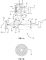
- Fig. 1a shows schematically a system 10 for performing dual path, two-dimensional Optical Coherence Tomography (OCT) on an object 11 lying in a specific plane 12 in order to measure a physical characteristic of the object.
- the system 10 comprises an extended broadband light source 13 for producing an incident light beam 14 and a dual beam interferometer 15 for intercepting the incident light beam and directing it via a beam splitter 16 that splits the incident beam into first and second component beams 17 and 18, respectively.
- the interferometer 15 directs the second component beam 18 on to a moveable mirror 19 for creating an optical path difference between the first component beam 17 and a reflection 20 of the second component beam 18.
- a focusing lens 21 having a focal plane 22 is configured for focusing the first component beam 17 and the reflection 20 of the second component beam to form a fringe pattern 23 on the focal plane 22.
- the fringe pattern 23 comprises a series of concentric circles of different colors as shown schematically in Fig. 1b .
- a configurable imaging system shown generally as 25 images the fringe pattern 23 on to the plane 12 so as to allow two-dimensional measurement of the object without spatial scanning.
- a second focusing lens 26 between the light source 13 and the interferometer 15 located relative to the light source so as to direct the incident beam 14 as a collimated beam on to the interferometer. This requires that the light source 13 be displaced from the second focusing lens 26 by a distance equal to the focal length of the lens 26. The lens 26 then focuses the light source as a parallel light beam whose image is superimposed on to the fringe pattern.
- the configurable imaging system 25 comprises a beam splitter 30 that directs the light emanating from the fringe pattern 23 and images it using a first imaging lens 31 on to the layered object 11 and transmits the light reflected therefrom through a second imaging lens 32 on to a camera 33.
- the component wavelengths of the broadband light source are focused by the focusing lens 21 so that the fringe pattern includes colored fringes.
- the fringe pattern may be annular or linear in shape.
- the color of the colored fringes changes as a function of displacement of the object from the focal plane of the imaging system 25 thus allowing quantitative measurement of a location of a point on the object as a function of the color of the fringe pattern at this point.
- the pattern of the colored fringes changes as a function of displacement of the object from the focal plane of the imaging system 25 thus allowing quantitative measurement of a location of a point on the object as a function of the fringe pattern at this point.
- the superimposition of the light source's image and the fringe pattern is undesirable in which case the light source 13 may be configured to direct the incident beam as a non-collimated beam on to the interferometer.
- the image of the light source is no longer formed of parallel beams and so is not superimposed on to the fringe pattern.
- the object 11 includes layers 34a, 34b, 34c etc. one of which e.g. 34a is used as a reference.
- the measured signal is the light reflected from each point of the object and is the interference of the reflections from all the layers at that point and it is proportional to the autocorrelation function of the object's structure.
- the object may also be part of an optical device such as an optical device that includes a lens upstream of the object to be measured.
- One optical device that lends itself to measurement using the invention is the eye wherein the object to be measured may be the retina, cornea, tear film or the intra-ocular lens of the eye.
- optical systems having lens upstream of the object to be measured as, of course, is the case when the retina is to be subjected to OCT have traditionally militated against the use of dual beam OCT which is actually an interferometer, since there is a need for a reference mirror.
- the reference arm should include an identical optical system and this cannot be attained in measuring variable biological objects.
- the invention avoids the need for the reference arm since the reference layer may be constituted by one surface in the retina.
- the imaging system 25 may be configured to form together with the lens of the optical device a compound lens having a focal plane on the specific plane of the optical device.
- the imaging system 25 together with the cornea, tear film and the intra-ocular lens of the eye form a compound lens, whose focus may be adjusted by configuring the imaging system 25 thereby ensuring that the fringe pattern is focused on to the desired object plane of the retina.
- this idea of avoiding the need for reference mirror and enabling measuring the retina in 2D at once rather than point by point can be implemented using any kind of light source, such as broadband or monochromatic light source, extended or point light source, swept source etc.
- the light source is an extended broadband light source. It can also implemented in point by point Time domain OCT or Fourier domain OCT
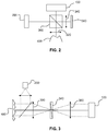
- Fig. 2 shows a dual path white light interferometer such as a Michelson or Linnik interferometer combined with a spectral imaging camera or a spectral imager to realize a 2D OCT in a FD-OCT type to obtain the surface structure of an object (topography).
- a fixed reference mirror is used and there is no need for stepping the interferometer's reference mirror.
- a spectral imaging camera 100 is incorporated with a White light interferometer such as Linnik interferometer 300.
- the light incoming from a broadband white light source 200 is split into two beams by a beam splitter 310.
- One beam is directed through an objective lens 320 to illuminate the object 400 and the other beam is directed to a reference mirror 360 through a lens 340.
- the light reflected from the object interferes with the light reflected from the mirror on a certain plane where a spectral imaging camera 100 is located. Due to the short coherence length of the white light, fringes are obtained only when the optical path difference between two beams is very small. The cause for this effect is that the different interference of the different wavelengths overlap and the overall result is that the visibility is reduced. When the optical path difference between two beams is very small, the different fringe patterns of the different wavelengths are still in phase and the fringes are still visible.
- the focal plane can be found accurately by analyzing the fringe pattern.
- moving the objective or the reference mirror causes the fringe pattern to scan the height of the object, and its contours are obtained.
- the intensity that is obtained by the white light interferometry is analyzed by means of a spectral imaging camera.
- This optical setup has the advantages of both the TD OCT and FD OCT.
- This interferometer provides the height data through the interference between the light that comes from the object and the light that comes from the reference mirror similarly to the FD OCT.
- the spectrum of the light is measured using dispersion devices such as grating.
- the optical path differences (translated to the heights in the object) are calculated by Fourier Transform.
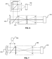
- Fig. 3 illustrates a common path interferometer such as Zernike phase contrast optical system combined with a spectral imaging camera or a spectral imager to realize a 2D OCT in a FD-OCT type for topography.
- a spectral imaging camera 100 is incorporated with a white light common path interferometer.
- the light incoming from a broadband light source 200 illuminates the object 400 which is located at the front focal plane of the lens 300.
- the reflected light is gathered by the lens 300 and propagates to the back focal plane of the lens 300.
- the second lens 360 creates a successive 2D Fourier transform of said modified wavefront on its back focal plane in which the spectral imaging camera 100 is located. Since the lower spatial frequencies of the object and the higher spatial frequencies interfere, an image of the object is created on the camera where now the phase map of the complex transmission or the complex reflection function of the object modifies the intensity map of the object accordingly.
- the lower spatial frequencies part of the wavefront can be considered as a reference beam for the higher spatial frequencies part of the wavefront. Accordingly, as the wavelength is changed the interference pattern at each point of the image will be oscillating between instructive and destructive interference in a similar manner to the dual path interferometer.
- the reference beam is the lower spatial frequencies part of the wavefront which is object dependent. Since each wavelength "sees” different object, the "reference beam” is different for each wavelength, the interference intensity oscillation envelope at each image's point might be modulated relative to the interference intensity oscillation envelope in the dual path interferometer. However, since the change of the "seen” object of close wavelengths is small and continuous it is expected that the main oscillation frequency between instructive and destructive interference is similar to the oscillation frequency in the dual path interferometer. Thus, the common path interferometer also provides the height data through the interference as the FD OCT.
- the spectrum of the light can be measured using dispersion devices such as grating in a scanning mode or a Hyperspectral camera in the imaging mode.
- the optical path differences (translated to the heights in the object) can be calculated by Fourier Transforming the spectral data.
- a common path interferometer it is meant a common path interferometer where the interference is obtained by amplitude division interference or by wavefront division interference.
- Fig. 4 illustrates another illustrative example in which the Hyperspectral Camera 100 attached to a static dual path interferometer 300 is specifically a Fourier Transform Hyperspectral Camera.
- a broadband light source 200 illuminates an object 400 through a static dual path interferometer 300.
- the light that is reflected from the object propagates through the static dual path interferometer 300 to the Hyperspectral Camera 100.
- the Hyperspectral Camera 100 consists of a beam splitter 160, a moving mirror 120, a static mirror 140 and a camera 180.
- This optical system is configured as an imaging system that images a point on the object into a pixel in the camera.
- the Fourier Transform Hyperspectral Camera is actually a camera that is attached to an interferometer.
- the camera creates the interferogram of each point of the scene which is the intensities of the incoming light from this point at different Optical Path Difference (OPDs) of the interferometer.
- OPDs Optical Path Difference
- Fourier transforming (or Cosine Fourier Transforming) the interferogram gives the spectrogram which is the spectrum data of the incoming light from that certain point.
- FD OCT the height of a certain point in the object is calculated by Fourier transforming the spectrogram of that point obtained by a fixed mirror interferometer.
- the signal at the Hyperspectral Camera is the interferogram in which by Fourier transforming it, the spectral data of the incoming light from each point is calculated.
- This setup is a kind of TD OCT but it releases the requirement for attaching a movable mirror interferometer to the object.
- a fixed mirror interferometer is attached to object and the interferogram is obtained inside the Hyperspectral Camera.
- Fig. 5 illustrates another illustrative example in which a camera 180 is attached to a static dual path interferometer 300 and a broadband light source 200 is modulated by a modulator 250.
- the modulated light illuminates the object 400 through the static dual path interferometer 300 and the reflected light propagates to the camera 180 through the static dual path interferometer 300.
- the Hyperspectral Camera is a camera that is attached to an interferometer.
- a Fourier Transform spectrometry inside the Hyperspectral Camera there is an interferometer.
- the interferometer inside the spectrometer modulates the incoming light differently for different wavelengths due to the destructive and instructive interference.
- v is the optical frequency
- k 1 and k 2 are the splitting parameters of the interferometer
- I i ( v ) is the intensity of incoming light in a certain optical frequency
- OPD is the Optical Path Difference of the two interferometer's arms.
- the spectrometer serves as a filter with a varying cosine spectral transmission function dependent on its current OPD between its mirrors.
- this filter can be located anywhere in the optical path of the light, and instead of placing the interferometer 250 just before the camera it can be also located just after the light source.
- the spectrum of the incoming light from the light source is modulated with a varying cosine function before impinging on the object by moving its movable mirror 260.
- the frequency of said varying cosine modulation function that modulated the spectrum is determined by the OPD of the two interferometer's mirrors 260 and 270. This implies that whenever the OPD in the modulating interferometer matches the OPD between the object 400 and the fixed mirror in the fixe interferometer, the signal on the detector is maximal.
- This example describes a kind of OCT in which there is no need for using a spectrometer and or moving mirrors in the interferometer as long as the spectrum of a broadband light source can be modulated. Modulating the light source serves as using an interferometer, thus whenever an interferometer is needed, the interferometer can be omitted as long as the light source is spectrally modulated as described above. Accordingly, the Michelson interferometer in FTS can be omitted when the light source is spectrally modulated.
- the modulating device is not limited to a Michelson interferometer and can be implemented using any kind of spectral modulators such as Babinet compensators, prisms or any interferometric schemes such as a scanning mirror interferometer or a Tunable Fabry-Perot interferometer.
- spectral modulators such as Babinet compensators, prisms or any interferometric schemes such as a scanning mirror interferometer or a Tunable Fabry-Perot interferometer.
- Fig. 6 illustrates another illustrative example in which a camera 180 is attached to a static common path interferometer 300 and a broadband light source 200 is modulated by a modulator 250.
- the modulated light illuminates the object 400 and the reflected light propagates to the camera 180 through the static dual path interferometer 300.
- the lower spatial frequencies part of the wavefront is considered as a reference beam for the higher spatial frequencies part of the wavefront.
- the interference intensity at each point of the image will be oscillate between instructive and destructive interference in a similar manner as in the dual path interferometer.
- the "reference beam" is different for each wavelength the frequency of the oscillation between the instructive and destructive interference might be modulated.
- the main frequency of the oscillation will be similar to the oscillation frequency in the dual path interferometer.
- the light source's spectrum is modulated by a varying cosine modulation function, it is expected that whenever a certain frequency of said varying cosine modulation function of the light source spectrum matches the main oscillation frequency between the instructive and destructive interference in the common path interferometer, the signal on the detector is maximal.
- the modulating device can be implemented using any kind of spectral modulators such as Babinet compensators, prisms or any interferometric schemes such as a scanning mirror interferometer or a Tunable Fabry-Perot interferometer.
- spectral modulators such as Babinet compensators, prisms or any interferometric schemes such as a scanning mirror interferometer or a Tunable Fabry-Perot interferometer.
- a camera is attached to a static common path interferometer and the light source is extended broadband light source with an arbitrary structure is modulated.
- a common path interferometer such a Zernike phase contrast system
- the 2D Fourier transform of the complex transmission or the complex reflection function in transmission or reflection mode
- the lower spatial frequencies part of the wavefront is delayed relative to the higher spatial frequencies part of the wavefront and at the back focal plane of the second lens both parts interfere to obtain the image.
- each point of the light source creates a 2D Fourier transform of the object in the light source's image plane and all these 2D Fourier transforms overlaps but they are not coherent.
- a phase plate with the light source's structure which is not a point that is located in the light source's image plane, delays not only the lower spatial frequencies part of each 2D Fourier transform of the object but also part of the higher spatial frequencies. Both parts of each 2D Fourier transform of the object that are coherent interfere at the back focal plane of the second lens. All the interference patterns created by each point of the light source overlap non-coherently to create the image. However, as the wavelength is changed the interference intensity at each point of the image will be oscillating between instructive and destructive interference in a similar manner.
- the main frequency of the intensity oscillation will be similar to the intensity oscillation frequency of the dual path interferometer.
- the signal on the detector should be maximal whenever a certain frequency of the varying cosine modulation function of the light source's spectrum matches the main intensity oscillation frequency in the common path interferometer.
- the structure of the extended light source may be any structure and the structure of the phase plate may be similar or not similar to the structure of the extended light source as long as part of each wavefront representing each 2D Fourier transform of the object is delayed to another part of the wavefront.
- the phase plate may be located in any plane in the optical system as long as part of each wavefront created by illumination of each point of the light source is delayed relative to another part of the wavefront.
- the modulating device is not restricted to a Michelson interferometer but it can be implemented using any kind of spectral modulators such as Babinet compensators, prisms or any interferometric schemes such as a scanning mirror interferometer or a Tunable Fabry-Perot interferometer.
- spectral modulators such as Babinet compensators, prisms or any interferometric schemes such as a scanning mirror interferometer or a Tunable Fabry-Perot interferometer.
- the spectrum of the reflected light from the object is calculated taking the following considerations into account.
- a Fourier Transform Hyperspectral Camera is attached to a fixed interferometer, the camera creates the interferogram of each point of the object and Fourier transforming the interferogram gives the spectrogram which is the spectrum data of the incoming light from that certain point.
- the reflected light from the object may be modulated owing to a non-fixed virtual reference beam and the calculated spectrogram may be incorrect.
- the modulation function of the spectrogram can be calculated and the incorrect calculated spectrogram can be repaired.
- Fig. 7 illustrates a spectral imaging camera or a spectral imager 100 combined with an imaging system to 300 obtain the layer structure of an object 400 without the need for a reference mirror.
- An extended broadband light source 200 illuminates the object.
- the light incoming from a white light source is split into two beams by a beam splitter.
- one beam is directed to the object and the other beam is directed to a reference mirror.
- the light reflected from the object interferes with the light reflected from the mirror.
- the mirror creates an image of the light source that is used as a reference light source and it interferes with the other light sources images that created by the different layers of the object.
- the present invention avoids the requirement for a reference mirror for applications where the thicknesses of the different layers are of importance and not the actual topometry.
- one of the images of the light source created by the different layers can be used as the reference light source for the other images.
- the imaging system gathers the light reflected light from the different layers at each point of the object into a conjugate point in the detectors array to obtain the interference between the light that is reflected from said different layers at each point of the object.
- the interference obtained is similar to the interference that is obtained when a reference mirror is used except that in this setup one of the layers is used as reference mirror for the other layers instead of using an additional reference mirror.
- the intensity function is an autocorrelation function but when one layer has higher reflection coefficient it can serve as a reference.
- the interference can be analyzed to obtain the thicknesses of the different layers in the same manner as is analyzed in a white light interferometry by means of a spectral imaging camera that is attached to the imaging optical system as described above.
- Fig. 8 illustrates a camera 180 attached to an imaging system 300 and where an extended broadband light source 200 is modulated by a modulator 250.
- the modulated light illuminates a layered object 400.
- a spectrally modulated light source serves as using an interferometer in a FTS, and the interferometer can be omitted as long as the light source is spectrally modulated as described above and thus, the Michelson interferometer in FTS can be omitted when the light source is spectrally modulated.
- one layer of the object can be used as the reference for the other layers in the object.
- the imaging system gathers the light reflected from the different layers at each point of the object into an image point in the detectors array.
- the reflected light from the different layers at each point of the object interfere to obtain the resulting intensity in that image point.
- the interference obtained is similar to the interference that is obtained when a reference mirror is used except that in this setup one of the layers is used as the reference for the other layers instead of using an additional reference mirror.
- the interference can be analyzed to obtain the thicknesses of the different layers in the same manner as described above.
- the 2D spectral analysis can be done by means of a spectral imaging camera that is attached to the imaging optical system as described above. However, as described in previous embodiments, when the light source is spectrally modulated, the spectral imaging camera can be replaced by a monochromatic camera.
- a priori knowledge of the spectral characteristics of the different layers of the object can be used to analyze the signal in different wavelength bands. By comparing the signals that would be obtained in different wavelength bands, some ambiguities in interpreting the results can be removed.
Landscapes
- Physics & Mathematics (AREA)
- General Physics & Mathematics (AREA)
- Health & Medical Sciences (AREA)
- Life Sciences & Earth Sciences (AREA)
- General Health & Medical Sciences (AREA)
- Radiology & Medical Imaging (AREA)
- Nuclear Medicine, Radiotherapy & Molecular Imaging (AREA)
- Medical Informatics (AREA)
- Engineering & Computer Science (AREA)
- Biomedical Technology (AREA)
- Heart & Thoracic Surgery (AREA)
- Ophthalmology & Optometry (AREA)
- Molecular Biology (AREA)
- Surgery (AREA)
- Animal Behavior & Ethology (AREA)
- Biophysics (AREA)
- Public Health (AREA)
- Veterinary Medicine (AREA)
- Investigating Or Analysing Materials By Optical Means (AREA)
- Instruments For Measurement Of Length By Optical Means (AREA)
Description
- The present invention relates to surface optical measurements, and more particularly, to a method and apparatus for measuring the surface and layers of an object.
- Optical Coherence Tomography (OCT) is a technique for obtaining sub-surface images of translucent or opaque materials at a resolution equivalent to a low-power microscope. It is effectively 'optical ultrasound', imaging reflections from within tissue to provide cross-sectional images. It is known to use Optical Coherence Tomography (OCT) for taking cross-sectional pictures of the retina in order to diagnose and follow treatment in certain eye conditions and diseases.
- Light in an OCT system is broken into two arms-a sample arm (containing the item of interest) and a reference arm (usually a mirror). The combination of reflected light from the sample arm and reference light from the reference arm gives rise to an interference pattern, but only if light from both arms have an optical difference of less than a coherence length. By scanning the mirror in the reference arm, a reflectivity profile of the sample can be obtained (this is time domain OCT). Areas of the sample that reflect back a lot of light will create greater interference than areas that do not. Any light that is outside the short coherence length will not interfere. This reflectivity profile, called an A-scan, contains information about the spatial dimensions and location of structures within the item of interest. A cross-sectional tomograph (B-scan) may be achieved by laterally combining a series of these axial depth scans (A-scan).
-
WO 2006/103663 discloses a method and apparatus for analyzing optical properties of an object using a light beam having a plurality of amplitudes, phases and polarizations of a plurality of wavelengths impinging from the object, obtaining modified illuminations corresponding to the light beam, modulating the light beam, analyzing the modulated light beam, and obtaining a plurality of amplitudes, phases and polarizations maps of the plurality of wavelengths, which are used to determine the object's optical properties. - The use of OCT for modulating the light before it strikes the object is described, for example, in
WO 2008/087613 , which discloses an apparatus and method combining achromatic complex Fourier domain OCT signal reconstruction with a common path and dual beam configuration. Light is directed through an interferometer, which splits the light to a dual beam and directs the two beams to the object in a common path. The combined dual beam interacts with a multi-layered object to obtain tomograms of a single point of the object. A B scan is required. -
US Patent No. 7,281,801 describes a system and method for measuring the thickness of a tear film layer and the heights of tear menisci around upper and lower eyelids of an eye. A plurality of images are acquired between consecutive blinks the eye using optical coherence tomography (OCT). The images depict the tear film layer and tear menisci as distinct from the cornea of the eye. In an embodiment, a plurality of reflectivity profiles from an OCT image are aligned and averaged. The difference between a first peak and a second peak of the average reflectivity profile is measured to determine the thickness of the tear film layer. A B scan is required. - Alex Zlotnik et al. "Full Field Spectral Domain Optical Coherence Tomography with Improved Extended Depth of Focus", OSA/CLEO/QELS 2010 discloses the use of an extended light source by creating interference fringes at the focal plane of a lens. An interfering phase mask is used to extend the depth of focus.
- Drexler et al. "Dual Beam Optical Coherence Tomography" in Signal Identification for Ophthalmologic Diagnosis directs reference and object beams to the object. The light that is reflected back by the cornea serves as a reference for the light reflected by the retina. This requires a B scan and requires a sensor having very high spectral resolution owing to the high optical path difference between the reference beam and the object beam.
-
WO/2008/087613 discloses an apparatus and a method combining achromatic complex Fourier Domain OCT signal reconstruction with a common path and dual beam configuration. The apparatus directs a modulated interferometric point light source to an object to be measured and is not able to measure optical characteristics of a two-dimensional object within an optical system other than by point-by-point scanning. -
US 2009/0080739 discloses a similar approach for performing spectral OCT imaging on a target by repeatedly scanning the target along a transverse scanning line with an object beam derived from an OCT interferometer having a narrowband source. The wavelength of the narrowband source is modulated over a range of wavelengths at a rate that is slow relative to the rate of scanning the target. The object beam returned from the target is detected to produce a set of data obtained from multiple scans along said scanning line over the entire range of wavelengths. The data is then processed to extract an OCT image (typically a B-scan) of the target containing depth information. - The above-referenced publications are representative of those that use OCT to image successive points of an object and thus require scanning of the OCT beam over a complete area of interest. OCT systems of this type involve the use of short coherent light, that is, light with a distinct spectral width and therefore short time coherence. The object is scanned point by point along a line extending on the object surface in the x-direction by the measurement beam of an interferometer. Under every surface point the measurement beam also penetrates into the object (in the z-direction) and the diffusely reflected light is interfered with the reference beam of the interferometer. Interference occurs because of the use of short coherence light only when the measurement beam and reference beam have the same path length within the coherence length.
- The literature recognizes the deficiency of such an approach and addresses the need to perform area imaging. Thus, for example,
US Patent No. 7,695,140 (Fercher ) describes an ophthalmologic measuring method that can depict three-dimensional structures of the interfaces of an eye by means of low coherence interferometry based on reference points. To this end, the pupil is illuminated at a number of points by a low coherence light source. The measurement radiation reflected at these points by the interfaces and surfaces of the eye is superimposed with a reference radiation. The measurement data generated thereby are spectrally split up by a diffraction grating, projected onto a two-dimensional detector array, and routed to a control unit that determines a three-dimensional structure of all intraocular interfaces and surfaces of the eye. This makes it possible to determine the depth positions of the measuring beams at many pupil points with a single image taken by the array camera by illuminating the pupil with an aperture grid, and the reference mirror contains a periodic phase grid. -
US Patent No. 6,810,140 discloses a system for three dimensional real-time imaging apparatus of the ocular retina, wherein laser rays are formed into a two dimensional ray surface sequentially with time by using a polygon mirror motor and galvanometer and irradiated on the almost transparent retina through the pupil. The optical system is complex and the polygon mirror performs optical scanning. -
WO 2012/035170 and Oh W Y, et al., "Spectrally-modulated full-field optical coherence microscopy for ultrahigh-resolution endoscopic imaging" (XP002640122) describe OCT systems having features corresponding to the preamble of the independent claims. But they require use of a reference beam. - There is thus required a method and system that uses a dual beam and produces a two-dimensional area image without the need for scanning.
- The invention describes a method and an apparatus having the features of the respective independent claims for performing optical measurements by using a common-path interferometer and a modulated light source.
- It is therefore a first object of the present invention to provide a method and system that performs dual path, two-dimensional Optical Coherence Tomography (OCT) on an object lying in a specific plane in order to measure a physical characteristic of the object by means of a two-dimensional area image that avoids the need for point-by-point scanning.
- This object is realized in accordance with the invention by a system for performing dual path, two-dimensional Optical Coherence Tomography (OCT) on an object lying in a specific plane in order to measure a physical characteristic of the object, said system comprising:
- an extended broadband light source for producing an incident light beam,
- a spatial light modulator (SLM) that modulates, in time, the spectrum of the light source differently in the spatial domain to obtain, in time, different fringe patterns.
- The spatial light modulator (SLM) may consist of interferometers of any kind, tunable filters etc.
a configurable imaging system for imaging the fringe patterns on to said specific plane so as to allow two-dimensional measurement of the object without spatial scanning. - By "extended" is means that the light source is not a point light source and directs an incident beam over a large, i.e. extended area. Likewise, by "broadband" is meant that the light is not monochromatic. These two properties of the light source cooperate such that the components colors of the light source appear as colored fringes at the input to the imaging system. According to the invention the object is multi-layered, one of whose serves as the reference layer thus avoiding the need for a reference beam. In the case of the eye, the reference layer may be constituted by one surface in the retina.
- In one application of the invention the object whose physical characteristic is to be measured is an optical system having a lens upstream of the specific plane in the optical system where the object is located. More particularly, the optical system may be an eye whose lens is constituted by the combination of the cornea and the intra-ocular lens both of which act to refract incoming light. This has prevented use of two-dimensional OCT for measuring characteristics of the eye using the advantageous broadband light sources and interferometry without the need for point-by-point scanning. In general, measuring an object using interferometer requires that the reference arm and the object arm should be identical. If the object is located in an optical system, the reference arm should include an identical optical system and this cannot be attained in measuring Biological objects. However, in the invention, since the reference layer may be constituted by one surface in the retina, there is no need for the reference arm and the retina can be measured not point by point but in 2D at once.
- This idea of avoiding the need for reference mirror and enabling measuring the retina in 2D at once rather than point by point, can be implemented using any kind of light source, such as broadband or monochromatic light source, extended or point light source, swept source etc. For the purpose of the present invention as defined in claim 1, the light source is an extended broadband light source. It can also implemented in point by point Time domain OCT or Fourier domain OCT.
- In one embodiment of the invention, an extended broadband light source is modulated to produce interference fringes at the focal plane of a lens, which are then projected on to the object. This allows us to use an existing i.e. independent optical system to project the fringes on to the object.
- The spectrum of the light source is modulated be means of moving one mirror of a Michelson interferometer.
- By controlling the focal length of the projection system it is thus possible to control on which part of the object in 3D space we want to perform tomography.
- Furthermore since the fringes are located at the effective focal plane of the lens after the interferometer and the illumination system is a separate unit, we therefore separate between the image plane of the light source and the image plane of the fringes produced by the light source.
- The fringes at the focal plane of the lens will be of a different color pattern relative to out-of-focus fringes that are imaged in front of or behind the focal plane. So even without moving the interferometer's mirror in order to adjust the optical path difference (OPD), the colors and form of the fringes on the object may be used as an indication of depth.
- The invention finds application not only to measure the different layers of the retina but by changing the focus of the projection system may be used to measure the intraocular lens or tear film.
- In order to understand the invention and to see how it may be carried out in practice, embodiments will now be described, by way of non-limiting example only, with reference to the accompanying drawing wherein
Figures 2 to 8 are not related to the present invention but whose inclusion is for background explanation of the present invention, in which: -
Figs. 1a is a schematic diagram of an optical system according to an embodiment of the invention; -
Fig. 1b shows schematically a fringe pattern produced by the system ofFig. 1a ; -
Fig. 2 illustrates a dual path white light interferometer combined with a spectral imaging camera or a spectral imager; -
Fig. 3 illustrates a common path interferometer is combined with a spectral imaging camera or a spectral imager; -
Fig. 4 illustrates a a Fourier Transform Hyperspectral Camera that is attached to a static dual path interferometer; -
Fig. 5 illustrates a monochrome camera attached to a static dual path interferometer while the object is illuminated by a modulated broadband light source; -
Fig. 6 illustrates a monochrome camera attached to a static common path interferometer while the object is illuminated by a modulated broadband light source; -
Fig. 7 illustrates a spectral imaging camera or a spectral imager attached to an imaging system without a reference mirror; and -
Fig. 8 illustrates a monochrome camera attached to an imaging system while the object is illuminated by a modulated broadband light source. -
Fig. 1a shows schematically asystem 10 for performing dual path, two-dimensional Optical Coherence Tomography (OCT) on anobject 11 lying in aspecific plane 12 in order to measure a physical characteristic of the object. Thesystem 10 comprises an extendedbroadband light source 13 for producing anincident light beam 14 and adual beam interferometer 15 for intercepting the incident light beam and directing it via abeam splitter 16 that splits the incident beam into first and second component beams 17 and 18, respectively. Theinterferometer 15 directs thesecond component beam 18 on to amoveable mirror 19 for creating an optical path difference between thefirst component beam 17 and areflection 20 of thesecond component beam 18. A focusinglens 21 having afocal plane 22 is configured for focusing thefirst component beam 17 and thereflection 20 of the second component beam to form afringe pattern 23 on thefocal plane 22. Thefringe pattern 23 comprises a series of concentric circles of different colors as shown schematically inFig. 1b . - A configurable imaging system shown generally as 25 images the
fringe pattern 23 on to theplane 12 so as to allow two-dimensional measurement of the object without spatial scanning. In some embodiments there may be included a second focusinglens 26 between thelight source 13 and theinterferometer 15 located relative to the light source so as to direct theincident beam 14 as a collimated beam on to the interferometer. This requires that thelight source 13 be displaced from the second focusinglens 26 by a distance equal to the focal length of thelens 26. Thelens 26 then focuses the light source as a parallel light beam whose image is superimposed on to the fringe pattern. - The
configurable imaging system 25 comprises abeam splitter 30 that directs the light emanating from thefringe pattern 23 and images it using afirst imaging lens 31 on to the layeredobject 11 and transmits the light reflected therefrom through asecond imaging lens 32 on to acamera 33. - Preferably the component wavelengths of the broadband light source are focused by the focusing
lens 21 so that the fringe pattern includes colored fringes. The fringe pattern may be annular or linear in shape. - In some embodiments, the color of the colored fringes changes as a function of displacement of the object from the focal plane of the
imaging system 25 thus allowing quantitative measurement of a location of a point on the object as a function of the color of the fringe pattern at this point. - In some embodiments, the pattern of the colored fringes changes as a function of displacement of the object from the focal plane of the
imaging system 25 thus allowing quantitative measurement of a location of a point on the object as a function of the fringe pattern at this point. - In other embodiments, the superimposition of the light source's image and the fringe pattern is undesirable in which case the
light source 13 may be configured to direct the incident beam as a non-collimated beam on to the interferometer. The image of the light source is no longer formed of parallel beams and so is not superimposed on to the fringe pattern. - The
object 11 includeslayers - To this end, the
imaging system 25 may be configured to form together with the lens of the optical device a compound lens having a focal plane on the specific plane of the optical device. Thus, in the case of performing OCT on the retina, theimaging system 25 together with the cornea, tear film and the intra-ocular lens of the eye form a compound lens, whose focus may be adjusted by configuring theimaging system 25 thereby ensuring that the fringe pattern is focused on to the desired object plane of the retina. - As mentioned above, this idea of avoiding the need for reference mirror and enabling measuring the retina in 2D at once rather than point by point, can be implemented using any kind of light source, such as broadband or monochromatic light source, extended or point light source, swept source etc. For the purpose of the present invention as defined in claim 1, the light source is an extended broadband light source. It can also implemented in point by point Time domain OCT or Fourier domain OCT
-
Fig. 2 shows a dual path white light interferometer such as a Michelson or Linnik interferometer combined with a spectral imaging camera or a spectral imager to realize a 2D OCT in a FD-OCT type to obtain the surface structure of an object (topography). In the interferometer a fixed reference mirror is used and there is no need for stepping the interferometer's reference mirror. Aspectral imaging camera 100 is incorporated with a White light interferometer such asLinnik interferometer 300. In a white light Linnik interferometer, the light incoming from a broadbandwhite light source 200 is split into two beams by a beam splitter 310. One beam is directed through anobjective lens 320 to illuminate theobject 400 and the other beam is directed to areference mirror 360 through alens 340. The light reflected from the object interferes with the light reflected from the mirror on a certain plane where aspectral imaging camera 100 is located. Due to the short coherence length of the white light, fringes are obtained only when the optical path difference between two beams is very small. The cause for this effect is that the different interference of the different wavelengths overlap and the overall result is that the visibility is reduced. When the optical path difference between two beams is very small, the different fringe patterns of the different wavelengths are still in phase and the fringes are still visible. When the mirror is placed such that the fringes are obtained in the focal plane of the objective lens, the focal plane can be found accurately by analyzing the fringe pattern. In TD OCT, moving the objective or the reference mirror causes the fringe pattern to scan the height of the object, and its contours are obtained. - However, according to the present invention, at each point of the object, the intensity that is obtained by the white light interferometry is analyzed by means of a spectral imaging camera. This optical setup has the advantages of both the TD OCT and FD OCT. In this setup there is a static interferometer in the light path inside the optical system and there is no need for stepping the reference mirror as in FD OCT. This interferometer provides the height data through the interference between the light that comes from the object and the light that comes from the reference mirror similarly to the FD OCT. In the regular FD OCT the spectrum of the light is measured using dispersion devices such as grating. Using the spectral data, the optical path differences (translated to the heights in the object) are calculated by Fourier Transform. Since the spectral data occupies one dimension of the detectors array, there is a need for a spatial scan of the object in order to measure a complete 2D object. However in the suggested setup a Hyperspectral Camera is used to measure the 2D spectral data of a 2D object simultaneously thus there is no need for spatial scan.
-
Fig. 3 illustrates a common path interferometer such as Zernike phase contrast optical system combined with a spectral imaging camera or a spectral imager to realize a 2D OCT in a FD-OCT type for topography. In this embodiment aspectral imaging camera 100 is incorporated with a white light common path interferometer. In a common path interferometer based on Zernike phase contrast optical system, the light incoming from abroadband light source 200 illuminates theobject 400 which is located at the front focal plane of thelens 300. The reflected light is gathered by thelens 300 and propagates to the back focal plane of thelens 300. It is well known that when a coherent point light source illuminates an object which is located at the front focal plane of a lens, the 2D Fourier transform of the complex transmission or the complex reflection function (in transmission or reflection mode) is obtained in the light source's image plane. In a collimated light illuminating the object the 2D Fourier transform of the complex transmission or the complex reflection function is obtained in the back focal plane of thelens 300. In the back focal plane of thelens 300 there is Diffractive Optical Element (DOE) 340 that delays one part of the wavefront relative to the other part. In general, the phase plate is located in the center of the back focal plane, thus it delays the lower spatial frequencies of the object relative to the higher spatial frequencies by a phase delay ΔΦ=π/2. Thesecond lens 360 creates a successive 2D Fourier transform of said modified wavefront on its back focal plane in which thespectral imaging camera 100 is located. Since the lower spatial frequencies of the object and the higher spatial frequencies interfere, an image of the object is created on the camera where now the phase map of the complex transmission or the complex reflection function of the object modifies the intensity map of the object accordingly. For this kind of interferometer, the lower spatial frequencies part of the wavefront can be considered as a reference beam for the higher spatial frequencies part of the wavefront. Accordingly, as the wavelength is changed the interference pattern at each point of the image will be oscillating between instructive and destructive interference in a similar manner to the dual path interferometer. The main difference is that in the common path interferometer the reference beam is the lower spatial frequencies part of the wavefront which is object dependent. Since each wavelength "sees" different object, the "reference beam" is different for each wavelength, the interference intensity oscillation envelope at each image's point might be modulated relative to the interference intensity oscillation envelope in the dual path interferometer. However, since the change of the "seen" object of close wavelengths is small and continuous it is expected that the main oscillation frequency between instructive and destructive interference is similar to the oscillation frequency in the dual path interferometer. Thus, the common path interferometer also provides the height data through the interference as the FD OCT. In a similar manner, the spectrum of the light can be measured using dispersion devices such as grating in a scanning mode or a Hyperspectral camera in the imaging mode. The optical path differences (translated to the heights in the object) can be calculated by Fourier Transforming the spectral data. - An extension of this idea is when the interference of the common path interferometer is created by shearing the wavefront or part of it relative to itself or relative to other as in shear interferometry. As the wavelength is changed the interference intensity at each point of the image will be oscillating between instructive and destructive interference in a similar manner to the dual path interferometer and the height can be calculated by Fourier transforming the interferogram.
- It is to be understood that whenever hereafter a common path interferometer is mentioned it is meant a common path interferometer where the interference is obtained by amplitude division interference or by wavefront division interference.
-
Fig. 4 illustrates another illustrative example in which theHyperspectral Camera 100 attached to a staticdual path interferometer 300 is specifically a Fourier Transform Hyperspectral Camera. In this example, abroadband light source 200 illuminates anobject 400 through a staticdual path interferometer 300. The light that is reflected from the object propagates through the staticdual path interferometer 300 to theHyperspectral Camera 100. TheHyperspectral Camera 100 consists of abeam splitter 160, a movingmirror 120, astatic mirror 140 and acamera 180. This optical system is configured as an imaging system that images a point on the object into a pixel in the camera. The Fourier Transform Hyperspectral Camera is actually a camera that is attached to an interferometer. The camera creates the interferogram of each point of the scene which is the intensities of the incoming light from this point at different Optical Path Difference (OPDs) of the interferometer. Fourier transforming (or Cosine Fourier Transforming) the interferogram gives the spectrogram which is the spectrum data of the incoming light from that certain point. However, in FD OCT the height of a certain point in the object is calculated by Fourier transforming the spectrogram of that point obtained by a fixed mirror interferometer. This implies that when a Fourier Transform Hyperspectral Camera is attached to a fixed mirror dual path interferometer, there is no need for performing the Fourier Transform calculations twice - one for the Fourier Transform Hyperspectral Camera to obtain the spectrogram and one for the FD OCT that is realized by the fixed mirror dual path interferometer to obtain the interferogram from the spectogram. The Hyperspectral Camera provides already the required height data without calculations. Whenever the OPD in the interferometer inside the Hyperspectral Camera is equivalent to the OPD between a point on the object and the static reference mirror in the static interferometer object's arm, the signal on the detector is maximal. Actually the signal at the Hyperspectral Camera is the interferogram in which by Fourier transforming it, the spectral data of the incoming light from each point is calculated. This setup is a kind of TD OCT but it releases the requirement for attaching a movable mirror interferometer to the object. In this scheme a fixed mirror interferometer is attached to object and the interferogram is obtained inside the Hyperspectral Camera. -
Fig. 5 illustrates another illustrative example in which acamera 180 is attached to a staticdual path interferometer 300 and abroadband light source 200 is modulated by amodulator 250. The modulated light illuminates theobject 400 through the staticdual path interferometer 300 and the reflected light propagates to thecamera 180 through the staticdual path interferometer 300. - The Hyperspectral Camera is a camera that is attached to an interferometer. In a Fourier Transform spectrometry inside the Hyperspectral Camera there is an interferometer. The interferometer inside the spectrometer modulates the incoming light differently for different wavelengths due to the destructive and instructive interference. In a Fourier Transform based on Michelson interferometer, the mirror in one arm is moved and the transmitted light intensity at a certain interferometer state is given by:

- Where v is the optical frequency, k1 and k2 are the splitting parameters of the interferometer, Ii (v) is the intensity of incoming light in a certain optical frequency and OPD is the Optical Path Difference of the two interferometer's arms.
- When, k 1 = k 2 = 0.5 the transmitted light intensity is
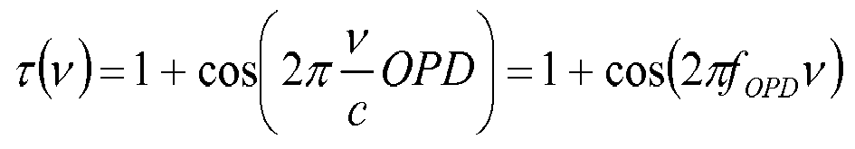

- The spectrometer serves as a filter with a varying cosine spectral transmission function dependent on its current OPD between its mirrors. However, this filter can be located anywhere in the optical path of the light, and instead of placing the
interferometer 250 just before the camera it can be also located just after the light source. In this configuration the spectrum of the incoming light from the light source is modulated with a varying cosine function before impinging on the object by moving itsmovable mirror 260. The frequency of said varying cosine modulation function that modulated the spectrum is determined by the OPD of the two interferometer'smirrors object 400 and the fixed mirror in the fixe interferometer, the signal on the detector is maximal. - This example describes a kind of OCT in which there is no need for using a spectrometer and or moving mirrors in the interferometer as long as the spectrum of a broadband light source can be modulated. Modulating the light source serves as using an interferometer, thus whenever an interferometer is needed, the interferometer can be omitted as long as the light source is spectrally modulated as described above. Accordingly, the Michelson interferometer in FTS can be omitted when the light source is spectrally modulated. The modulating device is not limited to a Michelson interferometer and can be implemented using any kind of spectral modulators such as Babinet compensators, prisms or any interferometric schemes such as a scanning mirror interferometer or a Tunable Fabry-Perot interferometer.
-
Fig. 6 illustrates another illustrative example in which acamera 180 is attached to a staticcommon path interferometer 300 and abroadband light source 200 is modulated by amodulator 250. The modulated light illuminates theobject 400 and the reflected light propagates to thecamera 180 through the staticdual path interferometer 300. In a common path interferometer, the lower spatial frequencies part of the wavefront is considered as a reference beam for the higher spatial frequencies part of the wavefront. As the wavelength is changed the interference intensity at each point of the image will be oscillate between instructive and destructive interference in a similar manner as in the dual path interferometer. However, since the "reference beam" is different for each wavelength the frequency of the oscillation between the instructive and destructive interference might be modulated. On the other hand, since the change of the "seen" object of close wavelengths is small and continuous it is expected that the main frequency of the oscillation will be similar to the oscillation frequency in the dual path interferometer. Thus, when the light source's spectrum is modulated by a varying cosine modulation function, it is expected that whenever a certain frequency of said varying cosine modulation function of the light source spectrum matches the main oscillation frequency between the instructive and destructive interference in the common path interferometer, the signal on the detector is maximal. - The modulating device can be implemented using any kind of spectral modulators such as Babinet compensators, prisms or any interferometric schemes such as a scanning mirror interferometer or a Tunable Fabry-Perot interferometer.
- In still another embodiment according to the present invention a camera is attached to a static common path interferometer and the light source is extended broadband light source with an arbitrary structure is modulated. In a common path interferometer such a Zernike phase contrast system, when a coherent point light source illuminates an object which is located at the front focal plane of a lens, the 2D Fourier transform of the complex transmission or the complex reflection function (in transmission or reflection mode) is obtained in the light source's image plane. In the light source's image plane, the lower spatial frequencies part of the wavefront is delayed relative to the higher spatial frequencies part of the wavefront and at the back focal plane of the second lens both parts interfere to obtain the image. When an extended light source is used, each point of the light source creates a 2D Fourier transform of the object in the light source's image plane and all these 2D Fourier transforms overlaps but they are not coherent. A phase plate with the light source's structure which is not a point that is located in the light source's image plane, delays not only the lower spatial frequencies part of each 2D Fourier transform of the object but also part of the higher spatial frequencies. Both parts of each 2D Fourier transform of the object that are coherent interfere at the back focal plane of the second lens. All the interference patterns created by each point of the light source overlap non-coherently to create the image. However, as the wavelength is changed the interference intensity at each point of the image will be oscillating between instructive and destructive interference in a similar manner. It is expected that the main frequency of the intensity oscillation will be similar to the intensity oscillation frequency of the dual path interferometer. Thus, when the light source's spectrum is modulated by a varying cosine modulation function, the signal on the detector should be maximal whenever a certain frequency of the varying cosine modulation function of the light source's spectrum matches the main intensity oscillation frequency in the common path interferometer.
- The structure of the extended light source may be any structure and the structure of the phase plate may be similar or not similar to the structure of the extended light source as long as part of each wavefront representing each 2D Fourier transform of the object is delayed to another part of the wavefront.
- The phase plate may be located in any plane in the optical system as long as part of each wavefront created by illumination of each point of the light source is delayed relative to another part of the wavefront.
- The modulating device is not restricted to a Michelson interferometer but it can be implemented using any kind of spectral modulators such as Babinet compensators, prisms or any interferometric schemes such as a scanning mirror interferometer or a Tunable Fabry-Perot interferometer.
- The spectrum of the reflected light from the object is calculated taking the following considerations into account. When a Fourier Transform Hyperspectral Camera is attached to a fixed interferometer, the camera creates the interferogram of each point of the object and Fourier transforming the interferogram gives the spectrogram which is the spectrum data of the incoming light from that certain point. However, using a common path interferometer instead of using a dual path interferometer, the reflected light from the object may be modulated owing to a non-fixed virtual reference beam and the calculated spectrogram may be incorrect. On the other hand, now that the object structure is measured, the modulation function of the spectrogram can be calculated and the incorrect calculated spectrogram can be repaired.
- This idea can be extended to increase the accuracy of the structure measurements. Now that the object structure is measured using the white light interferometry the low pass spatial frequencies of the object as seen by each wavelength can be calculated. These low pass spatial frequencies serve as the reference beam for each wavelength and now it is known. The intensity pattern obtained at each wavelength can be used to calculate the structure of the object more accurately.
-
Fig. 7 illustrates a spectral imaging camera or aspectral imager 100 combined with an imaging system to 300 obtain the layer structure of anobject 400 without the need for a reference mirror. An extendedbroadband light source 200 illuminates the object. In a white light interferometer, the light incoming from a white light source is split into two beams by a beam splitter. As mentioned above, in a conventional dual-path interferometer one beam is directed to the object and the other beam is directed to a reference mirror. The light reflected from the object interferes with the light reflected from the mirror. Actually, the mirror creates an image of the light source that is used as a reference light source and it interferes with the other light sources images that created by the different layers of the object. - The present invention avoids the requirement for a reference mirror for applications where the thicknesses of the different layers are of importance and not the actual topometry. Thus, in such an embodiment, one of the images of the light source created by the different layers can be used as the reference light source for the other images. The imaging system gathers the light reflected light from the different layers at each point of the object into a conjugate point in the detectors array to obtain the interference between the light that is reflected from said different layers at each point of the object. At each image's point, the interference obtained is similar to the interference that is obtained when a reference mirror is used except that in this setup one of the layers is used as reference mirror for the other layers instead of using an additional reference mirror. The intensity function is an autocorrelation function but when one layer has higher reflection coefficient it can serve as a reference. Thus, the interference can be analyzed to obtain the thicknesses of the different layers in the same manner as is analyzed in a white light interferometry by means of a spectral imaging camera that is attached to the imaging optical system as described above.
-
Fig. 8 illustrates acamera 180 attached to animaging system 300 and where an extendedbroadband light source 200 is modulated by amodulator 250. The modulated light illuminates alayered object 400. As described above, a spectrally modulated light source serves as using an interferometer in a FTS, and the interferometer can be omitted as long as the light source is spectrally modulated as described above and thus, the Michelson interferometer in FTS can be omitted when the light source is spectrally modulated. For some applications where the thicknesses of the different layers are of importance and not the actual topometry, one layer of the object can be used as the reference for the other layers in the object. The imaging system gathers the light reflected from the different layers at each point of the object into an image point in the detectors array. The reflected light from the different layers at each point of the object interfere to obtain the resulting intensity in that image point. At each image's point, the interference obtained is similar to the interference that is obtained when a reference mirror is used except that in this setup one of the layers is used as the reference for the other layers instead of using an additional reference mirror. Thus, the interference can be analyzed to obtain the thicknesses of the different layers in the same manner as described above. The 2D spectral analysis can be done by means of a spectral imaging camera that is attached to the imaging optical system as described above. However, as described in previous embodiments, when the light source is spectrally modulated, the spectral imaging camera can be replaced by a monochromatic camera. - There are several advantages when no reference mirror is used over the case when a reference mirror is used; The optical setup is much simpler; since no reference mirror is needed a regular optical system for imaging can also be used for measuring the layers thicknesses of the object and its spectral characteristics by only replacing its light source with a modulated light source; in some cases, the ratio between the signals to the background light is higher than in the case when a reference mirror is used since the light reflected from the reference mirror is also added to the background light.
- A priori knowledge of the spectral characteristics of the different layers of the object can be used to analyze the signal in different wavelength bands. By comparing the signals that would be obtained in different wavelength bands, some ambiguities in interpreting the results can be removed.
Claims (13)
- A system (10) for performing dual path, two-dimensional Optical Coherence Tomography (OCT) on an object (11) having a plurality of layers, and lying in a specific plane (12) in order to measure a physical characteristic of the object, said system comprising:an extended broadband light source (13) for producing an incident light beam (14),a dual beam interferometer (15) that comprises first a beam splitter (16) and that is configured to intercept the incident light beam and direct the incident light beam via the first beam splitter (16) such that the first beam splitter (16) splits the incident beam into a first component beam (17) and a second component beam (18) and creates an optical path difference between the first component beam (17) and a reflection (20) of the second component beam (18),a focusing lens (21) having a focal plane (22) and that is configured to focus the first component beam and the reflection of the second component beam to form a fringe pattern (23) on the focal plane of the focusing lens,a camera (33), andcharacterised in that the system further comprises:a configurable imaging system (25) comprising a second beam splitter (30) that directs the light from the fringe pattern (23) andimages the fringe pattern using a first imaging lens (31) on to said specific plane in which the object lies, andtransmits the light reflected therefrom through a second imaging lens (32) on to the camera, such that the light reflected from each point of the object comprises interference of reflections from all the layers of the object at that point, such that one of the plurality of layers of the object serves as a reference layer thus avoiding the need for a reference beam, so as to allow two-dimensional measurement of the object without spatial scanning.
- The system according to claim 1, wherein the fringe pattern comprises different colored fringes.
- The system according to claim 2, wherein the color of the colored fringes changes as a function of displacement of the object from the focal plane of the imaging system thus allowing quantitative measurement of a location of a point on the object as a function of the color of the fringe pattern at said point.
- The system according to claim 2, wherein the pattern of the colored fringes changes as a function of displacement of the object from the focal plane of the imaging system thus allowing quantitative measurement of a location of a point on the object as a function of the fringe pattern at said point.
- The system according to any one of claims 1 to 4, wherein the fringe pattern is annular.
- The system according to any one of claims 1 to 5, further including a second focusing lens (26) between the light source and the interferometer and being located relative to the light source so as to direct the incident beam as a collimated beam on to the interferometer whereby an image of the light source is superimposed on to the fringe pattern.
- The system according to any one of claims 1 to 5, wherein the light source is configured to direct the incident beam as a non-collimated beam on to the interferometer whereby an image of the light source is not superimposed on to the fringe pattern.
- The system according to any one of claims 1 to 7, wherein the object includes an object that is part of an optical device that includes a lens, and wherein the configurable imaging system is configured to form a compound lens together with the lens of the optical device, the compound lens having a focal plane that lies on the specific plane in which the object lies.
- The system according to claim 8, wherein the optical device is an eye, and the object is a retina of the eye, or a cornea of the eye, or a tear film of the eye, or an intra-ocular lens of the eye.
- The system according to any one of claims 1-9, wherein the dual beam interferometer comprises a moveable mirror (19) for creating the optical path difference between the first component beam (17) and the reflection (20) of the second component beam (18).
- The system according to any one of claims 1-10, further comprising a modulator that modulates the spectrum of the light source according to a varying cosine function.
- The system according to any one of claims 1-10, wherein the camera comprises a hyperspectral camera.
- A method for performing dual path, two-dimensional Optical Coherence Tomography (OCT) on an object (11) having a plurality of layers and lying in a specific plane (12), in order to measure a physical characteristic of the object, said method comprising:producing an incident light beam (14), using an extended broadband light source (13);using a dual beam interferometer (15) that comprises a first beam splitter (16) to intercept the incident light beam and direct the incident light beam via the first beam splitter (16), such that the first beam splitter splits (16) the incident beam into a first component beam (17) and a second component beam (18) and creates an optical path difference between the first component beam (17) and a reflection (20) of the second component beam (18);using a focusing lens (21) having a focal plane (22), focusing the first component beam and the reflection of the second component beam to form a fringe pattern (23) on the focal plane of the focusing lens,characterised further by the steps of:using a configurable imaging system (25) comprising a second beam splitter (30) that directs the light from the fringe pattern (23) and images the fringe pattern using a first imaging lens (31) on to said specific plane in which the object lies, andtransmitting the light reflected therefrom through a second imaging lens (32) on to a camera (33), such that the light reflected from each point of the object comprises interference of reflections from all the layers of the object at that point, such that one of the plurality of layers of the object serves as a reference layer thus avoiding the need for a reference beam, so as to allow two-dimensional measurement of the object without spatial scanning.
Priority Applications (1)
| Application Number | Priority Date | Filing Date | Title |
|---|---|---|---|
| EP19174755.9A EP3567337A1 (en) | 2012-07-30 | 2013-07-28 | System for performing dual path, two-dimensional optical coherence tomography (oct) |
Applications Claiming Priority (2)
| Application Number | Priority Date | Filing Date | Title |
|---|---|---|---|
| IL221187A IL221187A (en) | 2012-07-30 | 2012-07-30 | System for performing dual beam, two-dimensional optical coherence tomography (oct) |
| PCT/IL2013/050641 WO2014020597A1 (en) | 2012-07-30 | 2013-07-28 | System for performing dual path, two-dimensional optical coherence tomography (oct) |
Related Child Applications (2)
| Application Number | Title | Priority Date | Filing Date |
|---|---|---|---|
| EP19174755.9A Division-Into EP3567337A1 (en) | 2012-07-30 | 2013-07-28 | System for performing dual path, two-dimensional optical coherence tomography (oct) |
| EP19174755.9A Division EP3567337A1 (en) | 2012-07-30 | 2013-07-28 | System for performing dual path, two-dimensional optical coherence tomography (oct) |
Publications (3)
| Publication Number | Publication Date |
|---|---|
| EP2880397A1 EP2880397A1 (en) | 2015-06-10 |
| EP2880397A4 EP2880397A4 (en) | 2016-06-29 |
| EP2880397B1 true EP2880397B1 (en) | 2019-06-26 |
Family
ID=50027354
Family Applications (2)
| Application Number | Title | Priority Date | Filing Date |
|---|---|---|---|
| EP13826457.7A Not-in-force EP2880397B1 (en) | 2012-07-30 | 2013-07-28 | System for performing dual path, two-dimensional optical coherence tomography (oct) |
| EP19174755.9A Withdrawn EP3567337A1 (en) | 2012-07-30 | 2013-07-28 | System for performing dual path, two-dimensional optical coherence tomography (oct) |
Family Applications After (1)
| Application Number | Title | Priority Date | Filing Date |
|---|---|---|---|
| EP19174755.9A Withdrawn EP3567337A1 (en) | 2012-07-30 | 2013-07-28 | System for performing dual path, two-dimensional optical coherence tomography (oct) |
Country Status (4)
| Country | Link |
|---|---|
| US (3) | US9696134B2 (en) |
| EP (2) | EP2880397B1 (en) |
| IL (1) | IL221187A (en) |
| WO (1) | WO2014020597A1 (en) |
Families Citing this family (20)
| Publication number | Priority date | Publication date | Assignee | Title |
|---|---|---|---|---|
| US11803044B2 (en) | 2014-01-18 | 2023-10-31 | Daylight Solutions, Inc. | Low-noise spectroscopic imaging system with steerable substantially coherent illumination |
| US10437033B2 (en) * | 2014-01-18 | 2019-10-08 | Daylight Solutions, Inc. | Modulating spectroscopic imaging system using substantially coherent illumination |
| JP6449310B2 (en) | 2014-01-18 | 2019-01-09 | デイライト ソリューションズ、インコーポレイテッド | Low noise spectral imaging system |
| US10054429B2 (en) * | 2014-05-18 | 2018-08-21 | Adom, Advanced Optical Technologies Ltd. | System for tomography and/or topography measurements of a layered objects |
| JP6696977B2 (en) * | 2014-09-19 | 2020-05-20 | カール・ツアイス・メディテック・アーゲー | Optical coherence tomography system with zoomable Kepler system |
| CA2978457A1 (en) | 2015-03-03 | 2016-09-09 | Regents Of The University Of Minnesota | Etv2 and uses thereof |
| BR112017028608A2 (en) | 2015-06-30 | 2018-09-04 | Univ Minnesota | humanized heart muscle |
| RU2018103093A (en) | 2015-06-30 | 2019-07-31 | Реджентс Оф Зэ Юниверсити Оф Миннесота | HUMANIZED skeletal muscle |
| AT518602B1 (en) * | 2016-05-03 | 2019-02-15 | Zeiss Carl Meditec Ag | Ophthalmic length measurement using a double-beam space-time domain Wavelength Tuning Short-coherence interferometry |
| PL3573511T3 (en) | 2017-01-28 | 2021-12-20 | Cylite Pty Ltd | Optical coherence metrology and tomography with improved registration |
| US10893796B2 (en) | 2018-01-26 | 2021-01-19 | Topcon Corporation | 2D multi-layer thickness measurement |
| JP2019154764A (en) * | 2018-03-13 | 2019-09-19 | 株式会社トプコン | Tear film thickness measurement apparatus and method |
| GB2573754A (en) * | 2018-05-14 | 2019-11-20 | Univ Court Univ St Andrews | Spatially-offset optical coherence tomography |
| EP3608625B1 (en) | 2018-08-07 | 2023-10-25 | Hexagon Technology Center GmbH | Oct measuring system |
| US10916163B1 (en) * | 2019-10-29 | 2021-02-09 | Disney Enterprises, Inc. | Large-scale infinity optics window for use in small facility packaging applications |
| CN112394528B (en) * | 2020-11-25 | 2022-07-22 | 上海思量量子科技有限公司 | High-resolution multicolor beam splitting system and photon filtering method thereof |
| JP7058901B1 (en) | 2021-12-24 | 2022-04-25 | のりこ 安間 | 3D imager |
| WO2022224917A1 (en) * | 2021-04-19 | 2022-10-27 | のりこ 安間 | Three-dimensional image pickup device |
| CN115096857B (en) * | 2022-06-10 | 2025-06-20 | 北京石油化工学院 | An OCT imaging method and device based on Airy light sheet line scanning |
| CN115684011B (en) * | 2022-10-10 | 2025-04-15 | 国家纳米科学中心 | Nanowire imaging device and group refractive index measurement method |
Family Cites Families (22)
| Publication number | Priority date | Publication date | Assignee | Title |
|---|---|---|---|---|
| KR100339259B1 (en) | 2000-03-16 | 2002-06-01 | 양연식 | Three dimensional real-time image apparatus of ocular retina |
| EP1430270A4 (en) * | 2001-09-21 | 2006-10-25 | Kmac | Apparatus for measuring thickness profile and refractive index distribution of multiple layers of thin films by means of two-dimensional reflectometry and method of measuring the same |
| US20050254059A1 (en) | 2004-05-14 | 2005-11-17 | Alphonse Gerard A | Low coherence interferometric system for optical metrology |
| DE102004037479A1 (en) | 2004-08-03 | 2006-03-16 | Carl Zeiss Meditec Ag | Fourier domain OCT ray tracing on the eye |
| US7281801B2 (en) | 2004-09-15 | 2007-10-16 | University Of Rochester | Tear dynamics measured with optical coherence tomography |
| US20080158550A1 (en) | 2005-03-29 | 2008-07-03 | Yoel Arieli | Spectral Imaging Camera and Applications |
| GB2432066A (en) | 2005-11-02 | 2007-05-09 | Oti Ophthalmic Technologies | Optical coherence tomography imaging using repeated scan at slowly changing wavelength |
| WO2008087613A2 (en) | 2007-01-20 | 2008-07-24 | Ecole Polytechnique Federale De Lausanne (Epfl) | Dual beam heterodyne fourier domain optical coherence tomography |
| WO2009058850A1 (en) | 2007-10-30 | 2009-05-07 | University Of Miami | System and method for imaging tear film on an ocular surface |
| US7878651B2 (en) * | 2007-12-26 | 2011-02-01 | Carl Zeiss Meditec, Inc. | Refractive prescription using optical coherence tomography |
| IL189352A0 (en) * | 2008-02-07 | 2008-11-03 | Shmuel Sternklar | Means of measuring the electromagnetic spectral response of materials and imaging through media |
| US7800760B2 (en) | 2008-04-17 | 2010-09-21 | Heidelberg Engineering Gmbh | System and method for high resolution imaging of cellular detail in the retina |
| WO2010019515A2 (en) * | 2008-08-10 | 2010-02-18 | Board Of Regents, The University Of Texas System | Digital light processing hyperspectral imaging apparatus |
| WO2010096634A1 (en) | 2009-02-23 | 2010-08-26 | Dimensional Photonics International, Inc. | Speckle noise reduction for a coherent illumination imaging system |
| US8797539B2 (en) | 2009-02-24 | 2014-08-05 | Michael Galle | System and method for a virtual reference interferometer |
| WO2010122530A1 (en) * | 2009-04-24 | 2010-10-28 | Ecole Polytechnique Federale De Lausanne (Epfl) | A method and apparatus for enhanced spatial bandwidth wavefronts reconstructed from digital interferograms or holograms |
| EP2243420A1 (en) * | 2009-04-24 | 2010-10-27 | Schmidt-Erfurth, Ursula | Method for determining exudates in the retina |
| US20120013849A1 (en) * | 2010-07-13 | 2012-01-19 | University Of Kent At Canterbury | Apparatus and method of monitoring and measurement using spectral low coherence interferometry |
| WO2012035170A1 (en) * | 2010-09-17 | 2012-03-22 | Lltech Inc. | Optical tissue sectioning using full field optical coherence tomography |
| WO2012035148A1 (en) | 2010-09-17 | 2012-03-22 | Lltech Management | Full-field optical coherence tomography system for imaging an object |
| GB2485175A (en) | 2010-11-03 | 2012-05-09 | Univ City | Optical imaging system using incoherent light and interference fringes |
| US9179843B2 (en) * | 2011-04-21 | 2015-11-10 | Hassan Ghaderi MOGHADDAM | Method and system for optically evaluating proximity to the inferior alveolar nerve in situ |
-
2012
- 2012-07-30 IL IL221187A patent/IL221187A/en active IP Right Grant
-
2013
- 2013-07-28 US US14/417,971 patent/US9696134B2/en not_active Expired - Fee Related
- 2013-07-28 WO PCT/IL2013/050641 patent/WO2014020597A1/en not_active Ceased
- 2013-07-28 EP EP13826457.7A patent/EP2880397B1/en not_active Not-in-force
- 2013-07-28 EP EP19174755.9A patent/EP3567337A1/en not_active Withdrawn
-
2017
- 2017-05-25 US US15/605,947 patent/US10288407B2/en not_active Expired - Fee Related
-
2019
- 2019-04-02 US US16/373,304 patent/US20190226829A1/en not_active Abandoned
Non-Patent Citations (1)
| Title |
|---|
| None * |
Also Published As
| Publication number | Publication date |
|---|---|
| US20190226829A1 (en) | 2019-07-25 |
| US20150168125A1 (en) | 2015-06-18 |
| US9696134B2 (en) | 2017-07-04 |
| EP3567337A1 (en) | 2019-11-13 |
| WO2014020597A1 (en) | 2014-02-06 |
| US10288407B2 (en) | 2019-05-14 |
| EP2880397A1 (en) | 2015-06-10 |
| US20170261308A1 (en) | 2017-09-14 |
| IL221187A (en) | 2017-01-31 |
| EP2880397A4 (en) | 2016-06-29 |
Similar Documents
| Publication | Publication Date | Title |
|---|---|---|
| US10288407B2 (en) | System for performing dual path, two-dimensional optical coherence tomography (OCT) | |
| US11872015B2 (en) | Apparatus and method for confocal microscopy using dispersed structured illumination | |
| US11471039B2 (en) | High resolution 3-D spectral domain optical imaging apparatus and method | |
| JP5149196B2 (en) | Sample measurement by interferometry | |
| US9861277B2 (en) | Wavefront analyser | |
| US8605287B2 (en) | Extended range imaging | |
| EP3627093B1 (en) | Apparatus for parallel fourier domain optical coherence tomography imaging and imaging method using parallel fourier domain optical coherence tomography | |
| CN114646613B (en) | Holographic dot matrix coherent imaging method and system | |
| JP5784100B2 (en) | Image forming apparatus and image forming method | |
| Irsch | Optical principles of OCT | |
| US20240344819A1 (en) | Spectral domain optical imaging with wavelength comb illumination |
Legal Events
| Date | Code | Title | Description |
|---|---|---|---|
| PUAI | Public reference made under article 153(3) epc to a published international application that has entered the european phase |
Free format text: ORIGINAL CODE: 0009012 |
|
| 17P | Request for examination filed |
Effective date: 20150224 |
|
| AK | Designated contracting states |
Kind code of ref document: A1 Designated state(s): AL AT BE BG CH CY CZ DE DK EE ES FI FR GB GR HR HU IE IS IT LI LT LU LV MC MK MT NL NO PL PT RO RS SE SI SK SM TR |
|
| AX | Request for extension of the european patent |
Extension state: BA ME |
|
| DAX | Request for extension of the european patent (deleted) | ||
| RA4 | Supplementary search report drawn up and despatched (corrected) |
Effective date: 20160601 |
|
| RIC1 | Information provided on ipc code assigned before grant |
Ipc: G01B 9/02 20060101AFI20160525BHEP Ipc: G02B 27/10 20060101ALI20160525BHEP Ipc: A61B 6/00 20060101ALI20160525BHEP |
|
| STAA | Information on the status of an ep patent application or granted ep patent |
Free format text: STATUS: EXAMINATION IS IN PROGRESS |
|
| 17Q | First examination report despatched |
Effective date: 20180619 |
|
| GRAP | Despatch of communication of intention to grant a patent |
Free format text: ORIGINAL CODE: EPIDOSNIGR1 |
|
| STAA | Information on the status of an ep patent application or granted ep patent |
Free format text: STATUS: GRANT OF PATENT IS INTENDED |
|
| INTG | Intention to grant announced |
Effective date: 20190114 |
|
| GRAS | Grant fee paid |
Free format text: ORIGINAL CODE: EPIDOSNIGR3 |
|
| GRAA | (expected) grant |
Free format text: ORIGINAL CODE: 0009210 |
|
| STAA | Information on the status of an ep patent application or granted ep patent |
Free format text: STATUS: THE PATENT HAS BEEN GRANTED |
|
| AK | Designated contracting states |
Kind code of ref document: B1 Designated state(s): AL AT BE BG CH CY CZ DE DK EE ES FI FR GB GR HR HU IE IS IT LI LT LU LV MC MK MT NL NO PL PT RO RS SE SI SK SM TR |
|
| REG | Reference to a national code |
Ref country code: GB Ref legal event code: FG4D |
|
| REG | Reference to a national code |
Ref country code: CH Ref legal event code: EP |
|
| REG | Reference to a national code |
Ref country code: AT Ref legal event code: REF Ref document number: 1148799 Country of ref document: AT Kind code of ref document: T Effective date: 20190715 |
|
| REG | Reference to a national code |
Ref country code: DE Ref legal event code: R096 Ref document number: 602013057199 Country of ref document: DE |
|
| REG | Reference to a national code |
Ref country code: IE Ref legal event code: FG4D |
|
| REG | Reference to a national code |
Ref country code: NL Ref legal event code: MP Effective date: 20190626 |
|
| PG25 | Lapsed in a contracting state [announced via postgrant information from national office to epo] |
Ref country code: NO Free format text: LAPSE BECAUSE OF FAILURE TO SUBMIT A TRANSLATION OF THE DESCRIPTION OR TO PAY THE FEE WITHIN THE PRESCRIBED TIME-LIMIT Effective date: 20190926 Ref country code: AL Free format text: LAPSE BECAUSE OF FAILURE TO SUBMIT A TRANSLATION OF THE DESCRIPTION OR TO PAY THE FEE WITHIN THE PRESCRIBED TIME-LIMIT Effective date: 20190626 Ref country code: FI Free format text: LAPSE BECAUSE OF FAILURE TO SUBMIT A TRANSLATION OF THE DESCRIPTION OR TO PAY THE FEE WITHIN THE PRESCRIBED TIME-LIMIT Effective date: 20190626 Ref country code: SE Free format text: LAPSE BECAUSE OF FAILURE TO SUBMIT A TRANSLATION OF THE DESCRIPTION OR TO PAY THE FEE WITHIN THE PRESCRIBED TIME-LIMIT Effective date: 20190626 Ref country code: HR Free format text: LAPSE BECAUSE OF FAILURE TO SUBMIT A TRANSLATION OF THE DESCRIPTION OR TO PAY THE FEE WITHIN THE PRESCRIBED TIME-LIMIT Effective date: 20190626 Ref country code: LT Free format text: LAPSE BECAUSE OF FAILURE TO SUBMIT A TRANSLATION OF THE DESCRIPTION OR TO PAY THE FEE WITHIN THE PRESCRIBED TIME-LIMIT Effective date: 20190626 |
|
| REG | Reference to a national code |
Ref country code: LT Ref legal event code: MG4D |
|
| PG25 | Lapsed in a contracting state [announced via postgrant information from national office to epo] |
Ref country code: GR Free format text: LAPSE BECAUSE OF FAILURE TO SUBMIT A TRANSLATION OF THE DESCRIPTION OR TO PAY THE FEE WITHIN THE PRESCRIBED TIME-LIMIT Effective date: 20190927 Ref country code: BG Free format text: LAPSE BECAUSE OF FAILURE TO SUBMIT A TRANSLATION OF THE DESCRIPTION OR TO PAY THE FEE WITHIN THE PRESCRIBED TIME-LIMIT Effective date: 20190926 Ref country code: RS Free format text: LAPSE BECAUSE OF FAILURE TO SUBMIT A TRANSLATION OF THE DESCRIPTION OR TO PAY THE FEE WITHIN THE PRESCRIBED TIME-LIMIT Effective date: 20190626 Ref country code: LV Free format text: LAPSE BECAUSE OF FAILURE TO SUBMIT A TRANSLATION OF THE DESCRIPTION OR TO PAY THE FEE WITHIN THE PRESCRIBED TIME-LIMIT Effective date: 20190626 |
|
| REG | Reference to a national code |
Ref country code: AT Ref legal event code: MK05 Ref document number: 1148799 Country of ref document: AT Kind code of ref document: T Effective date: 20190626 |
|
| PG25 | Lapsed in a contracting state [announced via postgrant information from national office to epo] |
Ref country code: CZ Free format text: LAPSE BECAUSE OF FAILURE TO SUBMIT A TRANSLATION OF THE DESCRIPTION OR TO PAY THE FEE WITHIN THE PRESCRIBED TIME-LIMIT Effective date: 20190626 Ref country code: RO Free format text: LAPSE BECAUSE OF FAILURE TO SUBMIT A TRANSLATION OF THE DESCRIPTION OR TO PAY THE FEE WITHIN THE PRESCRIBED TIME-LIMIT Effective date: 20190626 Ref country code: EE Free format text: LAPSE BECAUSE OF FAILURE TO SUBMIT A TRANSLATION OF THE DESCRIPTION OR TO PAY THE FEE WITHIN THE PRESCRIBED TIME-LIMIT Effective date: 20190626 Ref country code: NL Free format text: LAPSE BECAUSE OF FAILURE TO SUBMIT A TRANSLATION OF THE DESCRIPTION OR TO PAY THE FEE WITHIN THE PRESCRIBED TIME-LIMIT Effective date: 20190626 Ref country code: AT Free format text: LAPSE BECAUSE OF FAILURE TO SUBMIT A TRANSLATION OF THE DESCRIPTION OR TO PAY THE FEE WITHIN THE PRESCRIBED TIME-LIMIT Effective date: 20190626 Ref country code: PT Free format text: LAPSE BECAUSE OF FAILURE TO SUBMIT A TRANSLATION OF THE DESCRIPTION OR TO PAY THE FEE WITHIN THE PRESCRIBED TIME-LIMIT Effective date: 20191028 Ref country code: SK Free format text: LAPSE BECAUSE OF FAILURE TO SUBMIT A TRANSLATION OF THE DESCRIPTION OR TO PAY THE FEE WITHIN THE PRESCRIBED TIME-LIMIT Effective date: 20190626 |
|
| PG25 | Lapsed in a contracting state [announced via postgrant information from national office to epo] |
Ref country code: IT Free format text: LAPSE BECAUSE OF FAILURE TO SUBMIT A TRANSLATION OF THE DESCRIPTION OR TO PAY THE FEE WITHIN THE PRESCRIBED TIME-LIMIT Effective date: 20190626 Ref country code: SM Free format text: LAPSE BECAUSE OF FAILURE TO SUBMIT A TRANSLATION OF THE DESCRIPTION OR TO PAY THE FEE WITHIN THE PRESCRIBED TIME-LIMIT Effective date: 20190626 Ref country code: IS Free format text: LAPSE BECAUSE OF FAILURE TO SUBMIT A TRANSLATION OF THE DESCRIPTION OR TO PAY THE FEE WITHIN THE PRESCRIBED TIME-LIMIT Effective date: 20191026 Ref country code: ES Free format text: LAPSE BECAUSE OF FAILURE TO SUBMIT A TRANSLATION OF THE DESCRIPTION OR TO PAY THE FEE WITHIN THE PRESCRIBED TIME-LIMIT Effective date: 20190626 |
|
| REG | Reference to a national code |
Ref country code: CH Ref legal event code: PL |
|
| PG25 | Lapsed in a contracting state [announced via postgrant information from national office to epo] |
Ref country code: MC Free format text: LAPSE BECAUSE OF FAILURE TO SUBMIT A TRANSLATION OF THE DESCRIPTION OR TO PAY THE FEE WITHIN THE PRESCRIBED TIME-LIMIT Effective date: 20190626 Ref country code: TR Free format text: LAPSE BECAUSE OF FAILURE TO SUBMIT A TRANSLATION OF THE DESCRIPTION OR TO PAY THE FEE WITHIN THE PRESCRIBED TIME-LIMIT Effective date: 20190626 |
|
| REG | Reference to a national code |
Ref country code: BE Ref legal event code: MM Effective date: 20190731 |
|
| PG25 | Lapsed in a contracting state [announced via postgrant information from national office to epo] |
Ref country code: DK Free format text: LAPSE BECAUSE OF FAILURE TO SUBMIT A TRANSLATION OF THE DESCRIPTION OR TO PAY THE FEE WITHIN THE PRESCRIBED TIME-LIMIT Effective date: 20190626 Ref country code: PL Free format text: LAPSE BECAUSE OF FAILURE TO SUBMIT A TRANSLATION OF THE DESCRIPTION OR TO PAY THE FEE WITHIN THE PRESCRIBED TIME-LIMIT Effective date: 20190626 |
|
| PG25 | Lapsed in a contracting state [announced via postgrant information from national office to epo] |
Ref country code: BE Free format text: LAPSE BECAUSE OF NON-PAYMENT OF DUE FEES Effective date: 20190731 Ref country code: IS Free format text: LAPSE BECAUSE OF FAILURE TO SUBMIT A TRANSLATION OF THE DESCRIPTION OR TO PAY THE FEE WITHIN THE PRESCRIBED TIME-LIMIT Effective date: 20200224 Ref country code: CH Free format text: LAPSE BECAUSE OF NON-PAYMENT OF DUE FEES Effective date: 20190731 Ref country code: LI Free format text: LAPSE BECAUSE OF NON-PAYMENT OF DUE FEES Effective date: 20190731 Ref country code: LU Free format text: LAPSE BECAUSE OF NON-PAYMENT OF DUE FEES Effective date: 20190728 |
|
| REG | Reference to a national code |
Ref country code: DE Ref legal event code: R097 Ref document number: 602013057199 Country of ref document: DE |
|
| PLBE | No opposition filed within time limit |
Free format text: ORIGINAL CODE: 0009261 |
|
| STAA | Information on the status of an ep patent application or granted ep patent |
Free format text: STATUS: NO OPPOSITION FILED WITHIN TIME LIMIT |
|
| PG2D | Information on lapse in contracting state deleted |
Ref country code: IS |
|
| PG25 | Lapsed in a contracting state [announced via postgrant information from national office to epo] |
Ref country code: IE Free format text: LAPSE BECAUSE OF NON-PAYMENT OF DUE FEES Effective date: 20190728 |
|
| 26N | No opposition filed |
Effective date: 20200603 |
|
| PG25 | Lapsed in a contracting state [announced via postgrant information from national office to epo] |
Ref country code: SI Free format text: LAPSE BECAUSE OF FAILURE TO SUBMIT A TRANSLATION OF THE DESCRIPTION OR TO PAY THE FEE WITHIN THE PRESCRIBED TIME-LIMIT Effective date: 20190626 |
|
| PG25 | Lapsed in a contracting state [announced via postgrant information from national office to epo] |
Ref country code: CY Free format text: LAPSE BECAUSE OF FAILURE TO SUBMIT A TRANSLATION OF THE DESCRIPTION OR TO PAY THE FEE WITHIN THE PRESCRIBED TIME-LIMIT Effective date: 20190626 |
|
| PG25 | Lapsed in a contracting state [announced via postgrant information from national office to epo] |
Ref country code: MT Free format text: LAPSE BECAUSE OF FAILURE TO SUBMIT A TRANSLATION OF THE DESCRIPTION OR TO PAY THE FEE WITHIN THE PRESCRIBED TIME-LIMIT Effective date: 20190626 Ref country code: HU Free format text: LAPSE BECAUSE OF FAILURE TO SUBMIT A TRANSLATION OF THE DESCRIPTION OR TO PAY THE FEE WITHIN THE PRESCRIBED TIME-LIMIT; INVALID AB INITIO Effective date: 20130728 |
|
| PGFP | Annual fee paid to national office [announced via postgrant information from national office to epo] |
Ref country code: FR Payment date: 20210721 Year of fee payment: 9 |
|
| PGFP | Annual fee paid to national office [announced via postgrant information from national office to epo] |
Ref country code: GB Payment date: 20210722 Year of fee payment: 9 Ref country code: DE Payment date: 20210721 Year of fee payment: 9 |
|
| PG25 | Lapsed in a contracting state [announced via postgrant information from national office to epo] |
Ref country code: MK Free format text: LAPSE BECAUSE OF FAILURE TO SUBMIT A TRANSLATION OF THE DESCRIPTION OR TO PAY THE FEE WITHIN THE PRESCRIBED TIME-LIMIT Effective date: 20190626 |
|
| REG | Reference to a national code |
Ref country code: DE Ref legal event code: R119 Ref document number: 602013057199 Country of ref document: DE |
|
| GBPC | Gb: european patent ceased through non-payment of renewal fee |
Effective date: 20220728 |
|
| PG25 | Lapsed in a contracting state [announced via postgrant information from national office to epo] |
Ref country code: FR Free format text: LAPSE BECAUSE OF NON-PAYMENT OF DUE FEES Effective date: 20220731 |
|
| PG25 | Lapsed in a contracting state [announced via postgrant information from national office to epo] |
Ref country code: GB Free format text: LAPSE BECAUSE OF NON-PAYMENT OF DUE FEES Effective date: 20220728 Ref country code: DE Free format text: LAPSE BECAUSE OF NON-PAYMENT OF DUE FEES Effective date: 20230201 |