EP2879978B1 - Link member having replaceable wear component - Google Patents
Link member having replaceable wear component Download PDFInfo
- Publication number
- EP2879978B1 EP2879978B1 EP13745987.1A EP13745987A EP2879978B1 EP 2879978 B1 EP2879978 B1 EP 2879978B1 EP 13745987 A EP13745987 A EP 13745987A EP 2879978 B1 EP2879978 B1 EP 2879978B1
- Authority
- EP
- European Patent Office
- Prior art keywords
- leg portion
- opening
- wear
- conveyor belt
- link member
- Prior art date
- Legal status (The legal status is an assumption and is not a legal conclusion. Google has not performed a legal analysis and makes no representation as to the accuracy of the status listed.)
- Active
Links
Images




Classifications
-
- B—PERFORMING OPERATIONS; TRANSPORTING
- B65—CONVEYING; PACKING; STORING; HANDLING THIN OR FILAMENTARY MATERIAL
- B65G—TRANSPORT OR STORAGE DEVICES, e.g. CONVEYORS FOR LOADING OR TIPPING, SHOP CONVEYOR SYSTEMS OR PNEUMATIC TUBE CONVEYORS
- B65G17/00—Conveyors having an endless traction element, e.g. a chain, transmitting movement to a continuous or substantially-continuous load-carrying surface or to a series of individual load-carriers; Endless-chain conveyors in which the chains form the load-carrying surface
- B65G17/06—Conveyors having an endless traction element, e.g. a chain, transmitting movement to a continuous or substantially-continuous load-carrying surface or to a series of individual load-carriers; Endless-chain conveyors in which the chains form the load-carrying surface having a load-carrying surface formed by a series of interconnected, e.g. longitudinal, links, plates, or platforms
- B65G17/08—Conveyors having an endless traction element, e.g. a chain, transmitting movement to a continuous or substantially-continuous load-carrying surface or to a series of individual load-carriers; Endless-chain conveyors in which the chains form the load-carrying surface having a load-carrying surface formed by a series of interconnected, e.g. longitudinal, links, plates, or platforms the surface being formed by the traction element
-
- B—PERFORMING OPERATIONS; TRANSPORTING
- B65—CONVEYING; PACKING; STORING; HANDLING THIN OR FILAMENTARY MATERIAL
- B65G—TRANSPORT OR STORAGE DEVICES, e.g. CONVEYORS FOR LOADING OR TIPPING, SHOP CONVEYOR SYSTEMS OR PNEUMATIC TUBE CONVEYORS
- B65G17/00—Conveyors having an endless traction element, e.g. a chain, transmitting movement to a continuous or substantially-continuous load-carrying surface or to a series of individual load-carriers; Endless-chain conveyors in which the chains form the load-carrying surface
- B65G17/06—Conveyors having an endless traction element, e.g. a chain, transmitting movement to a continuous or substantially-continuous load-carrying surface or to a series of individual load-carriers; Endless-chain conveyors in which the chains form the load-carrying surface having a load-carrying surface formed by a series of interconnected, e.g. longitudinal, links, plates, or platforms
- B65G17/063—Conveyors having an endless traction element, e.g. a chain, transmitting movement to a continuous or substantially-continuous load-carrying surface or to a series of individual load-carriers; Endless-chain conveyors in which the chains form the load-carrying surface having a load-carrying surface formed by a series of interconnected, e.g. longitudinal, links, plates, or platforms the load carrying surface being formed by profiles, rods, bars, rollers or the like attached to more than one traction element
- B65G17/064—Conveyors having an endless traction element, e.g. a chain, transmitting movement to a continuous or substantially-continuous load-carrying surface or to a series of individual load-carriers; Endless-chain conveyors in which the chains form the load-carrying surface having a load-carrying surface formed by a series of interconnected, e.g. longitudinal, links, plates, or platforms the load carrying surface being formed by profiles, rods, bars, rollers or the like attached to more than one traction element the profiles, rods, bars, rollers or the like being interconnected by a mesh or grid-like structure
-
- B—PERFORMING OPERATIONS; TRANSPORTING
- B65—CONVEYING; PACKING; STORING; HANDLING THIN OR FILAMENTARY MATERIAL
- B65G—TRANSPORT OR STORAGE DEVICES, e.g. CONVEYORS FOR LOADING OR TIPPING, SHOP CONVEYOR SYSTEMS OR PNEUMATIC TUBE CONVEYORS
- B65G17/00—Conveyors having an endless traction element, e.g. a chain, transmitting movement to a continuous or substantially-continuous load-carrying surface or to a series of individual load-carriers; Endless-chain conveyors in which the chains form the load-carrying surface
- B65G17/06—Conveyors having an endless traction element, e.g. a chain, transmitting movement to a continuous or substantially-continuous load-carrying surface or to a series of individual load-carriers; Endless-chain conveyors in which the chains form the load-carrying surface having a load-carrying surface formed by a series of interconnected, e.g. longitudinal, links, plates, or platforms
- B65G17/08—Conveyors having an endless traction element, e.g. a chain, transmitting movement to a continuous or substantially-continuous load-carrying surface or to a series of individual load-carriers; Endless-chain conveyors in which the chains form the load-carrying surface having a load-carrying surface formed by a series of interconnected, e.g. longitudinal, links, plates, or platforms the surface being formed by the traction element
- B65G17/083—Conveyors having an endless traction element, e.g. a chain, transmitting movement to a continuous or substantially-continuous load-carrying surface or to a series of individual load-carriers; Endless-chain conveyors in which the chains form the load-carrying surface having a load-carrying surface formed by a series of interconnected, e.g. longitudinal, links, plates, or platforms the surface being formed by the traction element the surface being formed by profiles, rods, bars, rollers or the like
-
- B—PERFORMING OPERATIONS; TRANSPORTING
- B65—CONVEYING; PACKING; STORING; HANDLING THIN OR FILAMENTARY MATERIAL
- B65G—TRANSPORT OR STORAGE DEVICES, e.g. CONVEYORS FOR LOADING OR TIPPING, SHOP CONVEYOR SYSTEMS OR PNEUMATIC TUBE CONVEYORS
- B65G17/00—Conveyors having an endless traction element, e.g. a chain, transmitting movement to a continuous or substantially-continuous load-carrying surface or to a series of individual load-carriers; Endless-chain conveyors in which the chains form the load-carrying surface
- B65G17/06—Conveyors having an endless traction element, e.g. a chain, transmitting movement to a continuous or substantially-continuous load-carrying surface or to a series of individual load-carriers; Endless-chain conveyors in which the chains form the load-carrying surface having a load-carrying surface formed by a series of interconnected, e.g. longitudinal, links, plates, or platforms
- B65G17/08—Conveyors having an endless traction element, e.g. a chain, transmitting movement to a continuous or substantially-continuous load-carrying surface or to a series of individual load-carriers; Endless-chain conveyors in which the chains form the load-carrying surface having a load-carrying surface formed by a series of interconnected, e.g. longitudinal, links, plates, or platforms the surface being formed by the traction element
- B65G17/086—Conveyors having an endless traction element, e.g. a chain, transmitting movement to a continuous or substantially-continuous load-carrying surface or to a series of individual load-carriers; Endless-chain conveyors in which the chains form the load-carrying surface having a load-carrying surface formed by a series of interconnected, e.g. longitudinal, links, plates, or platforms the surface being formed by the traction element specially adapted to follow a curved path
-
- B—PERFORMING OPERATIONS; TRANSPORTING
- B65—CONVEYING; PACKING; STORING; HANDLING THIN OR FILAMENTARY MATERIAL
- B65G—TRANSPORT OR STORAGE DEVICES, e.g. CONVEYORS FOR LOADING OR TIPPING, SHOP CONVEYOR SYSTEMS OR PNEUMATIC TUBE CONVEYORS
- B65G17/00—Conveyors having an endless traction element, e.g. a chain, transmitting movement to a continuous or substantially-continuous load-carrying surface or to a series of individual load-carriers; Endless-chain conveyors in which the chains form the load-carrying surface
- B65G17/30—Details; Auxiliary devices
- B65G17/38—Chains or like traction elements; Connections between traction elements and load-carriers
- B65G17/40—Chains acting as load-carriers
-
- B—PERFORMING OPERATIONS; TRANSPORTING
- B65—CONVEYING; PACKING; STORING; HANDLING THIN OR FILAMENTARY MATERIAL
- B65G—TRANSPORT OR STORAGE DEVICES, e.g. CONVEYORS FOR LOADING OR TIPPING, SHOP CONVEYOR SYSTEMS OR PNEUMATIC TUBE CONVEYORS
- B65G2201/00—Indexing codes relating to handling devices, e.g. conveyors, characterised by the type of product or load being conveyed or handled
- B65G2201/02—Articles
- B65G2201/0202—Agricultural and processed food products
-
- B—PERFORMING OPERATIONS; TRANSPORTING
- B65—CONVEYING; PACKING; STORING; HANDLING THIN OR FILAMENTARY MATERIAL
- B65G—TRANSPORT OR STORAGE DEVICES, e.g. CONVEYORS FOR LOADING OR TIPPING, SHOP CONVEYOR SYSTEMS OR PNEUMATIC TUBE CONVEYORS
- B65G2207/00—Indexing codes relating to constructional details, configuration and additional features of a handling device, e.g. Conveyors
- B65G2207/48—Wear protection or indication features
Definitions
- the present invention relates to conveyor belts, according to the preamble of claim 1.
- Conveyor belt systems are commonly used in various industrial fields for material handling and processing purposes. For instance, conveyor systems are used within food processing systems in which food items are placed on the support surface of a conveyor belt and processed, while being conveyed from one location to another. Various types of conveyor belts exist, including modular conveyor belts, which are especially popular in food processing systems. Moreover, conveyor systems are often used in a helical accumulator such as that disclose in U.S. Pat. No. 5,070,999 to Layne et al . which allows storage of a large number of items in the conveyor system.
- US patent 5,954,187 which represents the closest prior art, has a drive mechanism, such as belts that travel on a straight path, around turns or along a helical track, and specifically concerns the conveyor rods and side link connections in such conveyor belts.
- a drive mechanism such as belts that travel on a straight path, around turns or along a helical track
- US 5,954,187 suggests a hook-shaped end of a link member engaging the drive mechanism, so as to avoid drive problems between the belt edge and the portion of the drive mechanism that engages the belt.
- Conveyor belts used in spiral ovens are driven by a spiral cage made with evenly spaced vertical bars or a smooth cage surface. Due to the high temperatures required in an oven, the cage surface that would normally be covered with plastic in ambient or freezing applications must instead be made with stainless steel. A typical conveyor belt used in food processing equipment would also be made of stainless steel.
- Conveyor belts used in these applications are made with links and rods.
- the rods terminate at either end with either a weld to the link or a button head welded to the link. A continuous series of these elements are assembled to create an endless conveyor belt.
- the conveyor belt comprises a sacrificial or replaceable wear component that is attached to a conveyor belt.
- the conveyor belt can be any type of conveyor belt, such as a grid-type or flat-wire conveyor belt.
- the wear component is attached by mechanical or other means to allow its removal after a certain wear limit has been achieved.
- the wear component can be made of plastic, ceramic or any material machined or molded.
- an advantage of embodiments of the present invention is that the wear component can be removed and a new component can be installed to bring the conveyor belt to nearly new condition. This will extend belt life because only the wear component needs to be replaced, rather than the entire belt. This saves time and money, and provides a new uniform wear surface upon which the belt can be driven.
- the wear component can be rounded, oval or flat, and can be used in standard or extended leg links.
- the component is "snapped" into a slot in the extended leg of the link.
- the component is snapped into the leg of the link.
- the component can be attached with a special adhesive.
- a link member is also described.
- the link member comprises first and second leg portions, a connecting portion and a wear component.
- Each leg portion comprises a first opening at a proximal end and a second opening at a distal end.
- the first leg portion further comprises a third opening.
- the connecting portion connects the first and second leg portions at the distal end thereof.
- the wear component is received in the third opening.
- a link member having a replaceable wear component is described.
- FIG. 1 is a top view of a link member 100 having a wear component 180, in accordance with one implementation of the invention.
- Link member 100 has a first leg portion 110, a connecting portion 115 and a second leg portion 120.
- Connecting portion 115 connects first leg portion 110 and second leg portion 120 at a distal end of link member 100.
- First leg portion 110 and second leg portion 120 extend proximally from connecting portion 115.
- first leg portion 110 and second leg portion 120 can have different lengths.
- link member 100 can be an extended leg link member in which first leg portion 110 extends further proximally ( i.e., has a longer length) than second leg portion 120.
- First leg portion 110 has a first opening 130 and a second opening 150.
- Second leg portion 120 has a first opening 140 and a second opening 160.
- First opening 130 of first leg portion 110 and first opening 140 of second leg portion 120 are positioned at a proximal end of link member 100.
- Second opening 150 of first leg portion 110 and second opening 160 of second leg portion 120 are positioned at a distal end of link member 100.
- Pivot rod 190 is received in first opening 130 of first leg portion 110 and first opening 140 of second leg portion 120.
- pivot rod 190 is welded directly to first leg portion 110 at first opening 130.
- pivot rod 190 may include a button head (not shown) at an end thereof, which is instead welded to first leg portion 110 or is freestanding.
- a second pivot rod (not shown) is received in second opening 150 of first leg portion 110 and second opening 160 of second leg portion 120, as well as the first openings of the first and second leg portions of an adjacent link member (not shown).
- Link member 100 and pivot rod 190 can be made of stainless steel or another metal.
- First leg portion 110 includes a third opening 170 in which a wear component 180 is removably positioned.
- third opening 170 is positioned between first opening 130 and second opening 150 in first leg portion 110.
- Wear component 180 has a head portion and two leg portions. The ends of the two leg portions of wear component 180 can have a slightly larger diameter than a central area of the two leg portions in order to retain wear component 180 within third opening 170.
- wear component 180 In order to insert wear component 180 into third opening 170, the two legs of wear component 180 can be compressed toward each other while being pushed into third opening 170 until the ends of the leg portions snap into place and the head portion of wear component 180 is positioned against first leg portion 110.
- wear component 180 can have a single leg portion that can be compressed and snapped into place within third opening 170, without the need for a second leg portion. In either embodiment, the head portion of wear component 180 protrudes beyond the weld or button head between pivot rod 190 and first leg portion 110.
- FIG. 2 is a top view of link member 100 having a wear component 280, in accordance with an alternative embodiment.
- wear component 280 is C-shaped and is both snapped into third opening 170 of first leg portion 110 and is clipped onto first leg portion 110.
- wear component 280 has two legs connected by an arch that covers the weld between pivot rod 190 and first leg portion 110.
- pivot rod 190 is directly welded to first leg portion 110 in this embodiment, it is contemplated that pivot rod 190 can further include a button head at an end thereof, and that the button head can instead be welded to first leg portion 110 or be freestanding.
- the arch of wear component 280 would cover either the weld between the button head of pivot rod 190 and first leg portion 110 or the button head itself.
- the first leg of wear component 280 is positioned within third opening 170 of first leg portion 110.
- Third opening 170 is positioned between first opening 130 and second opening 150 of first leg portion 110.
- the second leg of wear component 280 has a recessed portion configured to receive the proximal end of first leg portion 110, as well as an extended portion having a greater diameter than the recessed portion in order to retain the second leg of wear component 280 on first leg portion 110.
- the first leg of wear component 280 has a similar recess and extended portion that allows it to be snapped into third opening 170 and retained therein.
- FIG. 3 is a top view of a link member 300 having a wear component 380, in accordance with an alternative embodiment, not part of the present invention. Similar to link member 100, link member 300 has a first leg portion 310, a connecting portion 315 and a second leg portion 320. Connecting portion 315 connects first leg portion 310 and second leg portion 320 at a distal end of link member 300. First leg portion 310 and second leg portion 320 extend proximally from connecting portion 315. Although shown and described as being substantially equal in length, it is contemplated that first leg portion 310 and second leg portion 320 can have different lengths. For example, link member 300 can be an extended leg link member in which first leg portion 310 extends further proximally ( i.e., has a longer length) than second leg portion 320.
- First leg portion 310 has a first opening 330 and a second opening 350.
- Second leg portion 320 has a first opening 340 and a second opening 360.
- First opening 330 of first leg portion 310 and first opening 340 of second leg portion 320 are positioned at a proximal end of link member 100.
- Second opening 350 of first leg portion 310 and second opening 360 of second leg portion 320 are positioned at a distal end of link member 300.
- Pivot rod 390 is received in first opening 330 of first leg portion 310 and first opening 340 of second leg portion 320.
- pivot rod 390 has button head 395.
- Button head 395 has a larger diameter than first opening 330 of first leg portion 310 and first opening 340 of second leg portion 320.
- button head 395 retains pivot rod 390 in first opening 330 of first leg portion 310 and first opening 340 of second leg portion 320.
- pivot rod 390 is welded to second leg portion 320.
- a weld can be present between button head 395 and first leg portion 310; between pivot rod 390 and first leg portion 310; or that no weld can be present at all.
- a second pivot rod (not shown) is received in second opening 350 of first leg portion 310 and second opening 360 of second leg portion 320, as well as the first openings of the first and second leg portions of an adjacent link member (not shown).
- Link member 300 and pivot rod 390 can be made of any material, and can be made of, for example, stainless steel or another metal.
- wear component 380 is positioned over button head 395.
- Wear component 380 has a flat portion positioned against the flat surface of button head 395 and two side portions curved around the side surfaces of button head 395.
- the side portions of wear component 380 can be positioned continuously around the side surfaces of button head 395, or can be placed at any number of locations around the perimeter of button head 395 as needed to secure wear component 380 in place.
- button head 395 fits within a recessed area of wear component 380.
- Wear component 380 has a larger diameter at the end of the side portions proximate to first leg portion 310 than at the center of the side portions, i.e ., wear component 380 has a lip at the end of the side portions. Thus, wear component 380 can be pushed onto button head 395 and be retained by the end of the side portions hugging the edges of button head 395.
- FIG. 4 is a top view of a link member 300 having a wear component 480, in accordance with an alternative embodiment, not part of the present invention.
- Pivot rod 490 is received in first opening 330 of first leg portion 310 and first opening 340 of second leg portion 320.
- pivot rod 490 has a threaded end 495 that has a smaller diameter than the remainder of pivot rod 490.
- threaded end 495 can have the same or a larger diameter than the remainder of pivot rod 490.
- pivot rod 490 is welded to second leg portion 320.
- a weld can be present between threaded end 495 and first leg portion 310; between pivot rod 490 and first leg portion 310; or that no weld can be present at all.
- a second pivot rod (not shown) is received in second opening 350 of first leg portion 310 and second opening 360 of second leg portion 320, as well as the first openings of the first and second leg portions of an adjacent link member (not shown).
- Link member 300 and pivot rod 490 can be made of stainless steel or another metal.
- wear component 480 is threaded or screwed on to threaded end 495.
- wear component 480 has a larger diameter than first opening 330 of first leg portion 310 and first opening 340 of second leg portion 320.
- wear component 480 retains pivot rod 390 in first opening 330 of first leg portion 310 and first opening 340 of second leg portion 320.
- wear component 480 can be a speed nut or press-on nut (not shown).
- FIG. 5 is a top view of an extended leg link member 500 having a wear component 580, in accordance with an implementation of the invention.
- Extended leg link member 500 has a first leg portion 510 and second leg portion 520.
- Connecting portion 515 connects first leg portion 510 and second leg portion 520 at a distal end of link member 500.
- First leg portion 510 and second leg portion 520 extend proximally from connecting portion 515.
- first leg portion 510 is longer than second leg portion 520, i.e., extends further proximally than second leg portion 520.
- First leg portion 510 has a first opening 530 and a second opening 550.
- Second leg portion 520 has a first opening 540 and a second opening 560.
- Second opening 550 of first leg portion 510 and second opening 560 of second leg portion 520 are positioned at a distal end of extended leg link member 500.
- First leg portion 510 has a third opening 570 positioned at a proximal end of extended leg link member 500.
- First opening 530 of first leg portion 510 is positioned between third opening 570 and second opening 550 of first leg portion 510.
- First opening 540 of second leg portion 520 is positioned parallel to first opening 530 of first leg portion 510.
- Pivot rod 590 is received in first opening 530 of first leg portion 510 and first opening 540 of second leg portion 520.
- pivot rod 590 is welded directly to first leg portion 510 at first opening 530.
- pivot rod 590 may include a button head (not shown) at an end thereof which is instead welded to first leg portion 510, or a button head or pivot rod that is instead freestanding without a weld.
- a second pivot rod (not shown) is received in second opening 550 of first leg portion 510 and second opening 560 of second leg portion 520, as well as the first openings of the first and second leg portions of an adjacent link member (not shown).
- Link member 500 and pivot rod 590 can be made of stainless steel or another metal.
- Wear component 580 is removably positioned in third opening 570 of first leg portion 510.
- third opening 570 is positioned further proximally than first opening 530 of first leg portion 510, such that first opening 530 is positioned between third opening 570 and second opening 550.
- Wear component 580 has a head portion and two leg portions. The ends of the two leg portions of wear component 580 can have a slightly larger diameter than a central area of the two leg portions in order to retain wear component 580 within the third opening 570.
- wear component 580 In order to insert wear component 580 into third opening 570, the two legs of wear component 580 can be compressed toward each other while being pushed into third opening 570 until the ends of the leg portions snap into place and the head portion of wear component 580 is positioned against first leg portion 510.
- wear component 580 can have a single leg portion that can be compressed and snapped into place within third opening 570, without the need for a second leg portion. In either embodiment, the head portion of wear component 580 protrudes beyond the weld or button head between pivot rod 590 and first leg portion 510.
- FIG. 6 is a side view of an extended leg link member 600 having wear component 680, in accordance with an implementation of the invention.
- First leg portion 610 has a first opening 630 and a second opening 650.
- Second opening 650 is positioned at a distal end of extended leg link member 600.
- First leg portion 610 has a third opening 670 positioned at a proximal end of extended leg link member 600.
- First opening 630 is positioned between third opening 670 and second opening 650.
- Wear component 680 is removably positioned in third opening 670.
- third opening 670 and second opening 650 are slots, while first opening 630 is a hole.
- any combination of slots, holes, and other openings can be used for the first, second and third openings described herein.
- FIG. 7 is a top view of a conveyor belt comprising a plurality of extended leg link members having wear components 780, in accordance with an implementation of the invention.
- FIG. 7 is a top view of a conveyor belt comprising a plurality of extended leg link members 600 as shown in a side view in FIG. 6 .
- Each extended leg link member has a first leg portion 710 and a second leg portion 720.
- a connecting portion 715 connects each first leg portion 710 and second leg portion 720 at a distal end of each link member.
- First leg portion 710 and second leg portion 710 extend proximally from connecting portion 715. As in FIG.
- first leg portion 710 is longer than second leg portion 720, i.e., first leg portion 710 extends further proximally than second leg portion 720. Unlike FIG. 5 , however, the extended portion of first leg portion 710 also extends in a direction away from the welded end of pivot rods 790.
- Each first leg portion 710 of FIG. 7 has a first opening 730 and a second opening 750.
- Each second leg portion 720 has a first opening 740 and a second opening 760.
- Second opening 750 of first leg portion 710 and second opening 760 of second leg portion 720 are positioned at a distal end of each extended leg link member.
- Each first leg portion 710 has a third opening 770 positioned at a proximal end of each extended leg link member.
- First opening 730 of first leg portion 710 is positioned between third opening 770 and second opening 750 of first leg portion 710.
- First opening 740 of second leg portion 720 is positioned parallel to first opening 730 of first leg portion 710.
- Pivot rod 790 is received in first opening 730 of first leg portion 710 and first opening 740 or second leg portion 720.
- each pivot rod 790 is welded directly to first leg portion 710 at first opening 730.
- pivot rod 790 may include a button head (not shown) at an end thereof which is instead welded to first leg portion 710, or a button head or pivot rod that is instead freestanding without a weld.
- one or more pivot rods 790 may be alternatively or additionally welded to second leg portion 720 at first opening 740.
- An adjacent pivot rod 795 is received in second opening 750 of first leg portion 710 and second opening 760 of second leg portion 720, as well as the first openings of the first and second leg portions 735 and 745, respectively, of an adjacent extended leg link member.
- the extended leg link members and pivot rods can be made of stainless steel or another metal.
- Wear component 780 is removably positioned in third opening 770 of each first leg portion 710.
- Wear component 780 has a head portion, a single leg portion and a central portion between the head portion and the leg portion.
- the leg portion of wear component 780 has a slightly larger diameter than the central portion in order to retain wear component 780 within the third opening 770.
- wear component 780 In order to insert wear component 780 into third opening 770, the central portion of wear component 780 is aligned with a slot (such as slot 670 of FIG. 6 ). Wear component 780 is then pushed into the slot such that the head portion of wear component 780 protrudes on one side of first leg portion 710, and the leg portion of wear component 780 protrudes on the opposite side of first leg portion 710. Although shown and described with respect to a single leg portion, it is contemplated that wear component 780 can have two or more leg portions that can be compressed and pushed into the slot.
- the head portion of wear component 780 protrudes beyond the weld between pivot rod 790 and first leg portion 710 in order to provide a wear surface between the extended link members of the conveyor belt and a spiral cage driving the conveyor belt, as discussed further herein.
- FIGS. 8-10 are top perspective views and side perspective views of a conveyor belt 800 comprising extended leg link members having wear components 880, in accordance with an implementation of the invention.
- each extended leg link member has a first leg portion 810 and a second leg portion 820.
- a connecting portion 815 connects each first leg portion 820 and second leg portion 820.
- first leg portion 810 is longer than second leg portion 820, i.e., first leg portion 810 extends further proximally than second leg portion 820 in at least one direction away from second leg portion 820.
- the portion of first leg portion 810 extending beyond second leg portion 820 is referred to as the "extended portion" of first leg portion 810.
- Pivot rods 890 interconnect first openings of first and second leg portions of one extended leg link member with the second openings of first and second leg portions of an adjacent link member, and are welded to the first leg portions of the extended leg link member at an end 825.
- the extended leg link members and pivot rods can be made of any material, and can be made of, for example, stainless steel or another metal.
- Wear components 880 are removably positioned in a third opening on the extended portion of each first leg portion 810.
- Wear component 880 has a head portion, a single leg portion and a central portion between the head portion and the leg portion.
- the head and leg portions of wear component 880 have a larger diameter than the central portion in order to retain wear component 880 within the third opening.
- the head portion of wear component 880 is flat. However, it is contemplated that the head portion can instead be rounded or any other shape.
- wear component 880 In order to insert wear component 880 into the third opening, the leg portion of wear component 880 is aligned with the third opening; in this case, a hole. Wear component 880 is then pushed or snapped into the hole such that the head portion of wear component 880 protrudes on one side of first leg portion 810, and the leg portion of wear component 880 protrudes on the opposite side of first leg portion 810. Although shown and described with respect to a single leg portion, it is contemplated that wear component 880 can have two or more leg portions that can be compressed and pushed into the slot (such as is shown with two leg portions in FIG. 5 ).
- the head portion of wear component 880 protrudes beyond the weld 825 between pivot rod 890 and first leg portion 810 in order to provide a wear surface between the extended link members of the conveyor belt and a spiral cage driving the conveyor belt, as discussed further herein.
- the link members and conveyor belts described with respect to FIGS. 1-10 herein can be used in spiral ovens driven by spiral cages made with evenly spaced vertical bars or a smooth cage surface. Due to the high temperatures required in an oven, the cage surface that would normally be covered with plastic in ambient or freezing applications is instead made with stainless steel. Similarly, in these applications, the described link members and pivot rods can also be made of stainless steel.
- the wear components described herein with respect to FIGS. 1-10 can be made of a high-temperature plastic, i.e., a plastic having a melting point above 93°C.
- a plastic having a melting point above 93°C include, but are not limited to, acrylic (PMMA), polyoxymethylene (POM or acetal), polybutylene terephthalate (PBT), polyethylene terephthalate (PET), polycarbonate (PC), polyhydroxylalkanoates (PHAs), polyester, polyethylene (PE), polyether ether ketone (PEEK), polypropylene (PP), polystyrene (PS), polyvinylidene chloride (PVDC) and styrene-acrylonitrile (SAN).
- PMMA acrylic
- POM or acetal polybutylene terephthalate
- PET polyethylene terephthalate
- PC polycarbonate
- PHAs polyhydroxylalkanoates
- polyester polyethylene
- PE polyether ether
- described embodiments are cost-effective in that only the wear components need be made of such materials, and standard stainless steel can be maintained on the spiral cages, link members and pivot rods.
- the described wear components create a uniform wear surface that contact the metal spiral cage. Over time and use, the described wear components that become worn down can be easily removed, disposed of, and replaced by a new wear component, as described above.
Landscapes
- Engineering & Computer Science (AREA)
- Mechanical Engineering (AREA)
- Chain Conveyers (AREA)
- Belt Conveyors (AREA)
Description
- The present invention relates to conveyor belts, according to the preamble of claim 1.
- Conveyor belt systems are commonly used in various industrial fields for material handling and processing purposes. For instance, conveyor systems are used within food processing systems in which food items are placed on the support surface of a conveyor belt and processed, while being conveyed from one location to another. Various types of conveyor belts exist, including modular conveyor belts, which are especially popular in food processing systems. Moreover, conveyor systems are often used in a helical accumulator such as that disclose in
U.S. Pat. No. 5,070,999 to Layne et al . which allows storage of a large number of items in the conveyor system. Moreover,US patent 5,954,187 , which represents the closest prior art, has a drive mechanism, such as belts that travel on a straight path, around turns or along a helical track, and specifically concerns the conveyor rods and side link connections in such conveyor belts. To this end,US 5,954,187 suggests a hook-shaped end of a link member engaging the drive mechanism, so as to avoid drive problems between the belt edge and the portion of the drive mechanism that engages the belt. - Conveyor belts used in spiral ovens are driven by a spiral cage made with evenly spaced vertical bars or a smooth cage surface. Due to the high temperatures required in an oven, the cage surface that would normally be covered with plastic in ambient or freezing applications must instead be made with stainless steel. A typical conveyor belt used in food processing equipment would also be made of stainless steel.
- Spiral theory requires that the spiral cage in these applications be driven slightly faster than the belt edge. This difference in speed results in adhesive wear between the inside belt edge and the rotating cage surface. Conveyor belts used in these applications are made with links and rods. The rods terminate at either end with either a weld to the link or a button head welded to the link. A continuous series of these elements are assembled to create an endless conveyor belt.
- The wear that occurs between the rotating cage surface and the inside belt edge results in the reduction of thickness of the button head. If this wear goes unabated, the button head and weld thin to the point that the weld between the link and rod fails, leading to operation failure of the entire belt. This results in both product loss and machine down time. If wear of the inside button heads is noticed upon inspection, users, as required, will "repair" the belts by adding additional weld material to the button head in order to extend the belt life. This "repair" process is timely, costly and inconsistent.
- Thus, there exists a need for a cost-effective wear component that interfaces between the links and rods and the spiral cage. There also exists a need for a wear component that is quickly and easily replaceable. Further, there exists an unfulfilled need for such a wear component that can be made to fit a variety of shapes, sizes and types of conveyor belts.
- In view of the foregoing, one aspect of the present invention provides a conveyor belt according to claim 1. The conveyor belt comprises a sacrificial or replaceable wear component that is attached to a conveyor belt. The conveyor belt can be any type of conveyor belt, such as a grid-type or flat-wire conveyor belt. The wear component is attached by mechanical or other means to allow its removal after a certain wear limit has been achieved. The wear component can be made of plastic, ceramic or any material machined or molded.
- Thus, an advantage of embodiments of the present invention is that the wear component can be removed and a new component can be installed to bring the conveyor belt to nearly new condition. This will extend belt life because only the wear component needs to be replaced, rather than the entire belt. This saves time and money, and provides a new uniform wear surface upon which the belt can be driven.
- The wear component can be rounded, oval or flat, and can be used in standard or extended leg links. In one embodiment, the component is "snapped" into a slot in the extended leg of the link. In another embodiment, the component is snapped into the leg of the link. Alternatively, the component can be attached with a special adhesive.
- A link member is also described. The link member comprises first and second leg portions, a connecting portion and a wear component. Each leg portion comprises a first opening at a proximal end and a second opening at a distal end. The first leg portion further comprises a third opening. The connecting portion connects the first and second leg portions at the distal end thereof. The wear component is received in the third opening.
- Still other aspects, features and advantages of the present invention are readily apparent from the following detailed description, simply by illustrating a number of exemplary embodiments and implementations, including the best mode contemplated for carrying out the present invention. The present invention also is capable of other and different embodiments, and its several details can be modified in various respects, all without departing from the scope of the present invention as disclosed in the appended claims. Accordingly, the drawings and descriptions are to be regarded as illustrative in nature, and not as restrictive.
- The present invention will be understood more fully from the detailed description given below and from the accompanying drawings of various embodiments of the invention, which, however, should not be taken to limit the invention to the specific embodiments, but are for explanation and understanding only.
-
FIG. 1 is a top view of a link member having a wear component in accordance with an embodiment of the invention. -
FIG. 2 is a top view of a link member having a wear component in accordance with another embodiment. -
FIG. 3 is a top view of a link member having a wear component not part of the present invention. -
FIG. 4 is a top view of a link member having a wear component not part of the present invention. -
FIG. 5 is a top view of an extended leg link member having a wear component in accordance with an embodiment of the invention. -
FIG. 6 is a side view of an extended leg link member having a wear component in accordance with an embodiment of the invention. -
FIG. 7 is a top view of a conveyor belt comprising extended leg link members having wear components in accordance with an embodiment of the invention. -
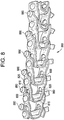
FIG. 8 is a top perspective view of a conveyor belt comprising extended leg link members having wear components in accordance with an embodiment of the invention. -
FIG. 9 is a side perspective view of a conveyor belt comprising extended leg link members having wear components in accordance with an embodiment of the invention. -
FIG. 10 is a side perspective view of a conveyor belt comprising extended leg link members having wear components in accordance with an embodiment of the invention. - A link member having a replaceable wear component is described.
- Referring now to the drawings, wherein like reference numerals designate identical or corresponding parts throughout the several views,
FIG. 1 is a top view of alink member 100 having awear component 180, in accordance with one implementation of the invention.Link member 100 has afirst leg portion 110, a connectingportion 115 and asecond leg portion 120. Connectingportion 115 connectsfirst leg portion 110 andsecond leg portion 120 at a distal end oflink member 100.First leg portion 110 andsecond leg portion 120 extend proximally from connectingportion 115. Although shown and described as being substantially equal in length, it is contemplated thatfirst leg portion 110 andsecond leg portion 120 can have different lengths. For example,link member 100 can be an extended leg link member in whichfirst leg portion 110 extends further proximally (i.e., has a longer length) thansecond leg portion 120. -
First leg portion 110 has afirst opening 130 and asecond opening 150.Second leg portion 120 has afirst opening 140 and asecond opening 160. First opening 130 offirst leg portion 110 andfirst opening 140 ofsecond leg portion 120 are positioned at a proximal end oflink member 100.Second opening 150 offirst leg portion 110 andsecond opening 160 ofsecond leg portion 120 are positioned at a distal end oflink member 100. -
Pivot rod 190 is received infirst opening 130 offirst leg portion 110 andfirst opening 140 ofsecond leg portion 120. In this embodiment,pivot rod 190 is welded directly tofirst leg portion 110 atfirst opening 130. It is contemplated, however, thatpivot rod 190 may include a button head (not shown) at an end thereof, which is instead welded tofirst leg portion 110 or is freestanding. A second pivot rod (not shown) is received insecond opening 150 offirst leg portion 110 andsecond opening 160 ofsecond leg portion 120, as well as the first openings of the first and second leg portions of an adjacent link member (not shown).Link member 100 andpivot rod 190 can be made of stainless steel or another metal. -
First leg portion 110 includes athird opening 170 in which awear component 180 is removably positioned. In this embodiment,third opening 170 is positioned betweenfirst opening 130 andsecond opening 150 infirst leg portion 110.Wear component 180 has a head portion and two leg portions. The ends of the two leg portions ofwear component 180 can have a slightly larger diameter than a central area of the two leg portions in order to retainwear component 180 withinthird opening 170. - In order to insert
wear component 180 intothird opening 170, the two legs ofwear component 180 can be compressed toward each other while being pushed intothird opening 170 until the ends of the leg portions snap into place and the head portion ofwear component 180 is positioned againstfirst leg portion 110. Although shown and described with respect to two leg portions, it is contemplated thatwear component 180 can have a single leg portion that can be compressed and snapped into place withinthird opening 170, without the need for a second leg portion. In either embodiment, the head portion ofwear component 180 protrudes beyond the weld or button head betweenpivot rod 190 andfirst leg portion 110. -
FIG. 2 is a top view oflink member 100 having awear component 280, in accordance with an alternative embodiment. In this embodiment, wearcomponent 280 is C-shaped and is both snapped intothird opening 170 offirst leg portion 110 and is clipped ontofirst leg portion 110. As shown inFIG. 2 , wearcomponent 280 has two legs connected by an arch that covers the weld betweenpivot rod 190 andfirst leg portion 110. As described above, althoughpivot rod 190 is directly welded tofirst leg portion 110 in this embodiment, it is contemplated thatpivot rod 190 can further include a button head at an end thereof, and that the button head can instead be welded tofirst leg portion 110 or be freestanding. In those embodiments, the arch ofwear component 280 would cover either the weld between the button head ofpivot rod 190 andfirst leg portion 110 or the button head itself. - The first leg of
wear component 280 is positioned withinthird opening 170 offirst leg portion 110.Third opening 170 is positioned betweenfirst opening 130 andsecond opening 150 offirst leg portion 110. The second leg ofwear component 280 has a recessed portion configured to receive the proximal end offirst leg portion 110, as well as an extended portion having a greater diameter than the recessed portion in order to retain the second leg ofwear component 280 onfirst leg portion 110. The first leg ofwear component 280 has a similar recess and extended portion that allows it to be snapped intothird opening 170 and retained therein. -
FIG. 3 is a top view of a link member 300 having awear component 380, in accordance with an alternative embodiment, not part of the present invention. Similar to linkmember 100, link member 300 has afirst leg portion 310, a connectingportion 315 and asecond leg portion 320. Connectingportion 315 connectsfirst leg portion 310 andsecond leg portion 320 at a distal end of link member 300.First leg portion 310 andsecond leg portion 320 extend proximally from connectingportion 315. Although shown and described as being substantially equal in length, it is contemplated thatfirst leg portion 310 andsecond leg portion 320 can have different lengths. For example, link member 300 can be an extended leg link member in whichfirst leg portion 310 extends further proximally (i.e., has a longer length) thansecond leg portion 320. -
First leg portion 310 has afirst opening 330 and asecond opening 350.Second leg portion 320 has afirst opening 340 and asecond opening 360. First opening 330 offirst leg portion 310 andfirst opening 340 ofsecond leg portion 320 are positioned at a proximal end oflink member 100.Second opening 350 offirst leg portion 310 andsecond opening 360 ofsecond leg portion 320 are positioned at a distal end of link member 300. -
Pivot rod 390 is received infirst opening 330 offirst leg portion 310 andfirst opening 340 ofsecond leg portion 320. In this embodiment,pivot rod 390 hasbutton head 395.Button head 395 has a larger diameter thanfirst opening 330 offirst leg portion 310 andfirst opening 340 ofsecond leg portion 320. Thus,button head 395 retainspivot rod 390 infirst opening 330 offirst leg portion 310 andfirst opening 340 ofsecond leg portion 320. - In this embodiment, not part of the present invention,
pivot rod 390 is welded tosecond leg portion 320. However, it is contemplated that a weld can be present betweenbutton head 395 andfirst leg portion 310; betweenpivot rod 390 andfirst leg portion 310; or that no weld can be present at all. A second pivot rod (not shown) is received insecond opening 350 offirst leg portion 310 andsecond opening 360 ofsecond leg portion 320, as well as the first openings of the first and second leg portions of an adjacent link member (not shown). Link member 300 andpivot rod 390 can be made of any material, and can be made of, for example, stainless steel or another metal. - Unlike
link member 100, it is not necessary for link member 300 to have a third opening forwear component 380. Instead, wearcomponent 380 is positioned overbutton head 395.Wear component 380 has a flat portion positioned against the flat surface ofbutton head 395 and two side portions curved around the side surfaces ofbutton head 395. The side portions ofwear component 380 can be positioned continuously around the side surfaces ofbutton head 395, or can be placed at any number of locations around the perimeter ofbutton head 395 as needed to securewear component 380 in place. In other words,button head 395 fits within a recessed area ofwear component 380.Wear component 380 has a larger diameter at the end of the side portions proximate tofirst leg portion 310 than at the center of the side portions, i.e., wearcomponent 380 has a lip at the end of the side portions. Thus, wearcomponent 380 can be pushed ontobutton head 395 and be retained by the end of the side portions hugging the edges ofbutton head 395. -
FIG. 4 is a top view of a link member 300 having awear component 480, in accordance with an alternative embodiment, not part of the present invention.Pivot rod 490 is received infirst opening 330 offirst leg portion 310 andfirst opening 340 ofsecond leg portion 320. In this embodiment,pivot rod 490 has a threadedend 495 that has a smaller diameter than the remainder ofpivot rod 490. However, it is contemplated that threadedend 495 can have the same or a larger diameter than the remainder ofpivot rod 490. - In this embodiment, not part of the present invention,
pivot rod 490 is welded tosecond leg portion 320. However, it is contemplated that a weld can be present between threadedend 495 andfirst leg portion 310; betweenpivot rod 490 andfirst leg portion 310; or that no weld can be present at all. A second pivot rod (not shown) is received insecond opening 350 offirst leg portion 310 andsecond opening 360 ofsecond leg portion 320, as well as the first openings of the first and second leg portions of an adjacent link member (not shown). Link member 300 andpivot rod 490 can be made of stainless steel or another metal. - Again, unlike
link member 100, it is not necessary for link member 300 to have a third opening forwear component 480. Instead, wearcomponent 480 is threaded or screwed on to threadedend 495. In this embodiment, wearcomponent 480 has a larger diameter thanfirst opening 330 offirst leg portion 310 andfirst opening 340 ofsecond leg portion 320. Thus, wearcomponent 480 retainspivot rod 390 infirst opening 330 offirst leg portion 310 andfirst opening 340 ofsecond leg portion 320. In still another embodiment, not part of the present invention, wearcomponent 480 can be a speed nut or press-on nut (not shown). -
FIG. 5 is a top view of an extendedleg link member 500 having awear component 580, in accordance with an implementation of the invention. Extendedleg link member 500 has afirst leg portion 510 andsecond leg portion 520. Connectingportion 515 connectsfirst leg portion 510 andsecond leg portion 520 at a distal end oflink member 500.First leg portion 510 andsecond leg portion 520 extend proximally from connectingportion 515. In this embodiment,first leg portion 510 is longer thansecond leg portion 520, i.e., extends further proximally thansecond leg portion 520. -
First leg portion 510 has afirst opening 530 and asecond opening 550.Second leg portion 520 has afirst opening 540 and asecond opening 560.Second opening 550 offirst leg portion 510 andsecond opening 560 ofsecond leg portion 520 are positioned at a distal end of extendedleg link member 500.First leg portion 510 has athird opening 570 positioned at a proximal end of extendedleg link member 500. First opening 530 offirst leg portion 510 is positioned betweenthird opening 570 andsecond opening 550 offirst leg portion 510. First opening 540 ofsecond leg portion 520 is positioned parallel tofirst opening 530 offirst leg portion 510. -
Pivot rod 590 is received infirst opening 530 offirst leg portion 510 andfirst opening 540 ofsecond leg portion 520. In this embodiment,pivot rod 590 is welded directly tofirst leg portion 510 atfirst opening 530. It is contemplated, however, thatpivot rod 590 may include a button head (not shown) at an end thereof which is instead welded tofirst leg portion 510, or a button head or pivot rod that is instead freestanding without a weld. A second pivot rod (not shown) is received insecond opening 550 offirst leg portion 510 andsecond opening 560 ofsecond leg portion 520, as well as the first openings of the first and second leg portions of an adjacent link member (not shown).Link member 500 andpivot rod 590 can be made of stainless steel or another metal. -
Wear component 580 is removably positioned inthird opening 570 offirst leg portion 510. In this embodiment,third opening 570 is positioned further proximally thanfirst opening 530 offirst leg portion 510, such thatfirst opening 530 is positioned betweenthird opening 570 andsecond opening 550.Wear component 580 has a head portion and two leg portions. The ends of the two leg portions ofwear component 580 can have a slightly larger diameter than a central area of the two leg portions in order to retainwear component 580 within thethird opening 570. - In order to insert
wear component 580 intothird opening 570, the two legs ofwear component 580 can be compressed toward each other while being pushed intothird opening 570 until the ends of the leg portions snap into place and the head portion ofwear component 580 is positioned againstfirst leg portion 510. Although shown and described with respect to two leg portions, it is contemplated thatwear component 580 can have a single leg portion that can be compressed and snapped into place withinthird opening 570, without the need for a second leg portion. In either embodiment, the head portion ofwear component 580 protrudes beyond the weld or button head betweenpivot rod 590 andfirst leg portion 510. - In the embodiments described above with respect to
FIGS. 1-5 , the first, second and third openings can be holes, slots or a combination thereof. For example,FIG. 6 is a side view of an extendedleg link member 600 havingwear component 680, in accordance with an implementation of the invention. InFIG. 6 , onlyfirst leg portion 610 is shown.First leg portion 610 has afirst opening 630 and asecond opening 650.Second opening 650 is positioned at a distal end of extendedleg link member 600.First leg portion 610 has athird opening 670 positioned at a proximal end of extendedleg link member 600.First opening 630 is positioned betweenthird opening 670 andsecond opening 650.Wear component 680 is removably positioned inthird opening 670. As shown inFIG. 6 ,third opening 670 andsecond opening 650 are slots, whilefirst opening 630 is a hole. However, any combination of slots, holes, and other openings can be used for the first, second and third openings described herein. -
FIG. 7 is a top view of a conveyor belt comprising a plurality of extended leg link members havingwear components 780, in accordance with an implementation of the invention. In one embodiment,FIG. 7 is a top view of a conveyor belt comprising a plurality of extendedleg link members 600 as shown in a side view inFIG. 6 . Each extended leg link member has afirst leg portion 710 and asecond leg portion 720. A connectingportion 715 connects eachfirst leg portion 710 andsecond leg portion 720 at a distal end of each link member.First leg portion 710 andsecond leg portion 710 extend proximally from connectingportion 715. As inFIG. 5 ,first leg portion 710 is longer thansecond leg portion 720, i.e.,first leg portion 710 extends further proximally thansecond leg portion 720. UnlikeFIG. 5 , however, the extended portion offirst leg portion 710 also extends in a direction away from the welded end ofpivot rods 790. - Each
first leg portion 710 ofFIG. 7 has afirst opening 730 and asecond opening 750. Eachsecond leg portion 720 has afirst opening 740 and asecond opening 760.Second opening 750 offirst leg portion 710 andsecond opening 760 ofsecond leg portion 720 are positioned at a distal end of each extended leg link member. Eachfirst leg portion 710 has athird opening 770 positioned at a proximal end of each extended leg link member. First opening 730 offirst leg portion 710 is positioned betweenthird opening 770 andsecond opening 750 offirst leg portion 710. First opening 740 ofsecond leg portion 720 is positioned parallel tofirst opening 730 offirst leg portion 710. -
Pivot rod 790 is received infirst opening 730 offirst leg portion 710 andfirst opening 740 orsecond leg portion 720. In this embodiment, eachpivot rod 790 is welded directly tofirst leg portion 710 atfirst opening 730. It is contemplated, however, thatpivot rod 790 may include a button head (not shown) at an end thereof which is instead welded tofirst leg portion 710, or a button head or pivot rod that is instead freestanding without a weld. It is further contemplated that one ormore pivot rods 790 may be alternatively or additionally welded tosecond leg portion 720 atfirst opening 740. Anadjacent pivot rod 795 is received insecond opening 750 offirst leg portion 710 andsecond opening 760 ofsecond leg portion 720, as well as the first openings of the first andsecond leg portions -
Wear component 780 is removably positioned inthird opening 770 of eachfirst leg portion 710.Wear component 780 has a head portion, a single leg portion and a central portion between the head portion and the leg portion. The leg portion ofwear component 780 has a slightly larger diameter than the central portion in order to retainwear component 780 within thethird opening 770. - In order to insert
wear component 780 intothird opening 770, the central portion ofwear component 780 is aligned with a slot (such asslot 670 ofFIG. 6 ).Wear component 780 is then pushed into the slot such that the head portion ofwear component 780 protrudes on one side offirst leg portion 710, and the leg portion ofwear component 780 protrudes on the opposite side offirst leg portion 710. Although shown and described with respect to a single leg portion, it is contemplated thatwear component 780 can have two or more leg portions that can be compressed and pushed into the slot. In either embodiment, the head portion ofwear component 780 protrudes beyond the weld betweenpivot rod 790 andfirst leg portion 710 in order to provide a wear surface between the extended link members of the conveyor belt and a spiral cage driving the conveyor belt, as discussed further herein. -
FIGS. 8-10 are top perspective views and side perspective views of aconveyor belt 800 comprising extended leg link members havingwear components 880, in accordance with an implementation of the invention. As described previously, each extended leg link member has afirst leg portion 810 and asecond leg portion 820. A connectingportion 815 connects eachfirst leg portion 820 andsecond leg portion 820. As inFIG. 7 ,first leg portion 810 is longer thansecond leg portion 820, i.e.,first leg portion 810 extends further proximally thansecond leg portion 820 in at least one direction away fromsecond leg portion 820. The portion offirst leg portion 810 extending beyondsecond leg portion 820 is referred to as the "extended portion" offirst leg portion 810. - Pivot
rods 890 interconnect first openings of first and second leg portions of one extended leg link member with the second openings of first and second leg portions of an adjacent link member, and are welded to the first leg portions of the extended leg link member at anend 825. The extended leg link members and pivot rods can be made of any material, and can be made of, for example, stainless steel or another metal. - Wear
components 880 are removably positioned in a third opening on the extended portion of eachfirst leg portion 810.Wear component 880 has a head portion, a single leg portion and a central portion between the head portion and the leg portion. The head and leg portions ofwear component 880 have a larger diameter than the central portion in order to retainwear component 880 within the third opening. As shown in this embodiment, the head portion ofwear component 880 is flat. However, it is contemplated that the head portion can instead be rounded or any other shape. - In order to insert
wear component 880 into the third opening, the leg portion ofwear component 880 is aligned with the third opening; in this case, a hole.Wear component 880 is then pushed or snapped into the hole such that the head portion ofwear component 880 protrudes on one side offirst leg portion 810, and the leg portion ofwear component 880 protrudes on the opposite side offirst leg portion 810. Although shown and described with respect to a single leg portion, it is contemplated thatwear component 880 can have two or more leg portions that can be compressed and pushed into the slot (such as is shown with two leg portions inFIG. 5 ). In either embodiment, the head portion ofwear component 880 protrudes beyond theweld 825 betweenpivot rod 890 andfirst leg portion 810 in order to provide a wear surface between the extended link members of the conveyor belt and a spiral cage driving the conveyor belt, as discussed further herein. - The link members and conveyor belts described with respect to
FIGS. 1-10 herein can be used in spiral ovens driven by spiral cages made with evenly spaced vertical bars or a smooth cage surface. Due to the high temperatures required in an oven, the cage surface that would normally be covered with plastic in ambient or freezing applications is instead made with stainless steel. Similarly, in these applications, the described link members and pivot rods can also be made of stainless steel. - However, the wear components described herein with respect to
FIGS. 1-10 can be made of a high-temperature plastic, i.e., a plastic having a melting point above 93°C. Such plastics include, but are not limited to, acrylic (PMMA), polyoxymethylene (POM or acetal), polybutylene terephthalate (PBT), polyethylene terephthalate (PET), polycarbonate (PC), polyhydroxylalkanoates (PHAs), polyester, polyethylene (PE), polyether ether ketone (PEEK), polypropylene (PP), polystyrene (PS), polyvinylidene chloride (PVDC) and styrene-acrylonitrile (SAN). For extremely high temperature applications, polyether ether ketone (PEEK) is preferred, as it has a melting point of approximately 343°C. - Because high-temperature plastics such as polyether ether ketone (PEEK) can be expensive in large volumes, described embodiments are cost-effective in that only the wear components need be made of such materials, and standard stainless steel can be maintained on the spiral cages, link members and pivot rods. The described wear components create a uniform wear surface that contact the metal spiral cage. Over time and use, the described wear components that become worn down can be easily removed, disposed of, and replaced by a new wear component, as described above.
- The present invention has been described in relation to particular examples, which are intended in all respects to be illustrative rather than restrictive. Those skilled in the art will appreciate that many different combinations of materials and components will be suitable for practicing the present invention.
- Other implementations of the invention will be apparent to those skilled in the art from consideration of the specification and practice of the invention disclosed herein. Various aspects and/or components of the described embodiments may be used singly or in any combination. It is intended that the specification and examples be considered as exemplary only, with the scope of the invention being indicated by the following claims.
Claims (19)
- A conveyor belt comprising:a plurality of metal link members (100, 500, 600), each link member of the plurality of link members comprising:a first leg portion and a second leg portion (110, 120, 510, 520, 710, 720, 810, 820), each of the first leg portion and the second leg portion comprising a first opening (130, 140, 530, 540, 730, 740) at a proximal end thereof and a second opening (150, 160, 550, 560, 750, 760) at a distal end thereof; anda connecting portion (115, 515, 715, 815) that connects the first leg portion and the second leg portion (110, 120, 510, 520, 710, 720, 810, 820) at the distal ends thereof;a plurality of pivot rods (190, 490, 590, 790, 890), each pivot rod of the plurality of pivot rods being received in the first opening (130, 140, 530, 540, 730, 740) of a separate link member of the plurality of link members (100, 500, 600) and the second opening (150, 160, 550, 560, 750, 760) of an adjacent link member of the plurality of link members to the separate link member; characterised in thatthe first leg portion of each link member of the plurality of link members comprises a third opening (170, 570, 670, 770),the conveyor belt further comprising a plurality of wear components (180, 280, 580, 680, 780, 880), each wear component of the plurality of wear components being received in the third opening (170, 570, 670, 770) of a separate link member of the plurality of link members, and each wear component of the plurality of wear components protruding beyond ends of the pivot rods extending through the first leg portion of the corresponding link member.
- The conveyor belt of claim 1, wherein each wear component of the plurality of wear components (180, 280, 580, 680, 780, 880) is made of a high-temperature plastic.
- The conveyor belt of claim 2, wherein the high-temperature plastic is polyether ether ketone (PEEK).
- The conveyor belt of any one of claims 1 to 3, wherein the first leg portion (510, 710, 810) of the plurality of link members are longer than the second leg portion (520, 720, 820) of the plurality of link members.
- The conveyor belt of any one of claims 1 to 4, wherein at least one wear component (180, 280, 580, 680, 780, 880) of the plurality of wear components is threaded into the third opening (170, 570, 670, 770) of a corresponding link member (100, 500, 600) of the at least one wear component.
- The conveyor belt of any one of claims 1 to 4, wherein at least one wear component (180, 280, 580, 680, 780, 880) of the plurality of wear components is mechanically deformed in the third opening (170, 570, 670, 770) of a corresponding link member (100, 500, 600) of the at least one wear component.
- The conveyor belt of any one of claims 1 to 4, wherein at least one wear component (180, 280, 580, 680, 780, 880) of the plurality of wear components is secured in the third opening (170, 570, 670, 770) of a corresponding link member (100, 500, 600) of the at least one wear component with adhesive.
- The conveyor belt of any one of claims 1 to 4, wherein at least one wear component of the plurality of wear components (180, 280) is snapped into the third opening (170) of a corresponding link member (100) of the at least one wear component.
- The conveyor belt of any one of claims 1 to 8, wherein the third openings (170) of the plurality of link members are positioned between the first opening (130) and the second opening (150) on respective first leg portions (110).
- The conveyor belt of any one of claims 1 to 8, wherein the third openings (570, 670, 770) of the plurality of link members are positioned between the first opening (530, 630, 730) and the proximal ends of respective first leg portions (510, 610, 710).
- The conveyor belt of any one of claims 1 to 10, wherein each wear component of the plurality of wear components (180, 280, 580, 680, 780, 880) is configured to contact a spiral cage.
- The conveyor belt of claim 11, wherein the spiral cage is metal, and the plurality of pivot rods (190, 590, 790, 890) are metal.
- The conveyor belt of any one of claims 1 to 12, wherein each wear component of the plurality of wear components protrudes from the first leg portion on opposing sides of the third opening (170, 570, 670, 770).
- The conveyor belt of any one of claims 1 to 13, wherein each pivot rod of the plurality of pivot rods (190, 590, 790, 890) includes a weld to a separate link member of the plurality of link members (100, 500, 600).
- The conveyor belt of any one of claims 1 to 14, wherein each pivot rod (190, 590, 790, 890) of the plurality of pivot rods is welded to the first leg portion (110, 510, 610, 710, 810) of a separate link member of the plurality of link members (100, 500, 600).
- The conveyor belt of claim 15, wherein each wear component (280) of the plurality of wear components covers the weld of a separate pivot rod of the plurality of pivot rods (190).
- The conveyor belt of any one of claims 1 to 16, wherein each wear component of the plurality of wear components (180, 280, 580, 680, 780, 880) is disposable.
- The conveyor belt of any one of claims 1 to 17, wherein each wear component of the plurality of wear components (180, 280, 580, 680, 780, 880) is replaceable.
- The conveyor belt of any one of claims 1 to 18, wherein each wear component of the plurality of wear components (180, 280, 580, 680, 780, 880) is attached to a separate link member of the plurality of link members (100, 500, 600) with adhesive.
Applications Claiming Priority (2)
| Application Number | Priority Date | Filing Date | Title |
|---|---|---|---|
| US13/562,820 US8857608B2 (en) | 2012-07-31 | 2012-07-31 | Link member having replaceable wear component |
| PCT/US2013/052739 WO2014022404A1 (en) | 2012-07-31 | 2013-07-30 | Link member having replaceable wear component |
Publications (2)
| Publication Number | Publication Date |
|---|---|
| EP2879978A1 EP2879978A1 (en) | 2015-06-10 |
| EP2879978B1 true EP2879978B1 (en) | 2017-08-23 |
Family
ID=48948550
Family Applications (1)
| Application Number | Title | Priority Date | Filing Date |
|---|---|---|---|
| EP13745987.1A Active EP2879978B1 (en) | 2012-07-31 | 2013-07-30 | Link member having replaceable wear component |
Country Status (8)
| Country | Link |
|---|---|
| US (1) | US8857608B2 (en) |
| EP (1) | EP2879978B1 (en) |
| JP (1) | JP6026658B2 (en) |
| KR (1) | KR101648491B1 (en) |
| BR (1) | BR112015002256B1 (en) |
| CA (1) | CA2880683C (en) |
| MX (1) | MX362342B (en) |
| WO (1) | WO2014022404A1 (en) |
Families Citing this family (6)
| Publication number | Priority date | Publication date | Assignee | Title |
|---|---|---|---|---|
| ITPD20120267A1 (en) * | 2012-09-14 | 2014-03-15 | Alit S R L | PERFECTED JERSEY FOR SIDE CHAIN FOR CONVEYOR BELTS |
| CN106470184B (en) * | 2015-08-14 | 2020-06-26 | 阿里巴巴集团控股有限公司 | Security authentication method, device and system |
| US10280004B2 (en) | 2017-03-03 | 2019-05-07 | Cambridge International Inc. | Direct edge drive conveyor belt |
| US11053081B2 (en) | 2019-05-08 | 2021-07-06 | Cambridge International, Inc. | Direct drive spiral conveyor belt systems and methods |
| US11305938B2 (en) | 2019-08-29 | 2022-04-19 | Cambridge International, Inc. | Active direct drive spiral conveyor belt systems and methods |
| CN111532663A (en) * | 2020-05-30 | 2020-08-14 | 金倍励金属(苏州)有限公司 | Metal mesh belt chain link structure |
Family Cites Families (45)
| Publication number | Priority date | Publication date | Assignee | Title |
|---|---|---|---|---|
| GB196050A (en) | 1922-01-11 | 1923-04-11 | Harry Simpson Pochin | Improvements relating to endless chains |
| US2547581A (en) | 1948-07-03 | 1951-04-03 | Albert G Kearns | Power transmission and conveyer line |
| US2619843A (en) | 1950-03-18 | 1952-12-02 | Charles W Kampfer | Universal link |
| FR1234348A (en) | 1958-07-09 | 1960-10-17 | Chain for carriers | |
| FR1251538A (en) | 1960-02-24 | 1961-01-20 | Buehler Ag Geb | Removable assembly for transport chains |
| LU40171A1 (en) | 1960-06-11 | 1961-07-24 | ||
| DE1159847B (en) | 1962-10-06 | 1963-12-19 | Hugo Mueller | Slatted conveyor |
| GB995391A (en) | 1963-05-10 | 1965-06-16 | Himpelm Engineers Ltd | Link conveyor belts |
| US3278000A (en) | 1964-12-14 | 1966-10-11 | Anson Ind Inc L | Conveyor chain with disconnectable ball bearing link joints |
| DE2048480A1 (en) | 1970-10-02 | 1972-04-06 | Hostert Automata | Transport chain |
| DE2150078C3 (en) | 1971-10-07 | 1981-05-14 | F.L. Smidth & Co. A/S, Koebenhavn | Bolt lock for chains |
| US3881593A (en) | 1974-01-28 | 1975-05-06 | Norton Co | Chain conveyor link and attachment therefor |
| US3944059A (en) | 1974-09-20 | 1976-03-16 | Garvey Corporation | Endless chain conveyor link |
| US4050323A (en) | 1976-01-12 | 1977-09-27 | Anson Thomas I | Pintle-type industrial conveyor chain |
| US4114467A (en) | 1976-12-02 | 1978-09-19 | Rexnord Inc. | Snap-on wear pad |
| GB2077685B (en) | 1979-07-18 | 1983-03-09 | Henrekson Ulf | Conveyor |
| DE3101209C2 (en) | 1981-01-16 | 1982-12-23 | Kabelschlepp Gmbh, 5900 Siegen | Flat top conveyor |
| US4490970A (en) | 1981-07-24 | 1985-01-01 | Superior Chain, Inc. | Conveyor link |
| US4518077A (en) | 1982-08-23 | 1985-05-21 | Rexnord Inc. | Polymeric snap-through attachment for a hollow rivet chain |
| DK152543C (en) | 1986-01-30 | 1988-08-01 | Poul Erik Damkjaer | Conveyor |
| JPH04226208A (en) | 1990-05-21 | 1992-08-14 | Ucc Corp | Module type conveyor belt |
| US5133449A (en) * | 1990-11-30 | 1992-07-28 | The Cambridge Wire Cloth Company | Frictional drive spiral conveyor system |
| US5280833A (en) * | 1991-08-27 | 1994-01-25 | Andre Robin | Turn conveyor with reduced friction feature |
| DE69510423T2 (en) | 1994-04-15 | 2000-02-24 | Jorgen Draebel | CONVEYOR CHAIN WITH A BASE CONSTRUCTED FROM CHAIN LINKS CROSS TO THE LENGTH DIRECTION OF THIS CONVEYOR CHAIN |
| US5566817A (en) | 1995-05-31 | 1996-10-22 | Meeker; William A. | Conveyor belt |
| US5954187A (en) | 1996-01-22 | 1999-09-21 | Cambridge, Inc. | Conveyor rod in side link connection |
| US6237750B1 (en) | 1996-04-16 | 2001-05-29 | Uni-Chains International | Transport band for conveying along a spiral path |
| US5775480A (en) * | 1996-06-14 | 1998-07-07 | The Laitram Corporation | Low-friction conveyor assembly |
| JP3626817B2 (en) * | 1996-07-25 | 2005-03-09 | 日本フイルコン株式会社 | Conveyor belt constituent unit piece and conveyor belt formed using the same |
| US5899322A (en) | 1996-08-22 | 1999-05-04 | Regina-Emerson Company | Retention clip for conveyor belts |
| US5782340A (en) * | 1997-03-06 | 1998-07-21 | Dolan; Rex H. | Tapered side support for conveyor belts |
| US6073756A (en) * | 1998-01-23 | 2000-06-13 | Uni-Chains A/S | Side-flexing conveyor belt |
| NL1010842C2 (en) * | 1998-12-18 | 2000-06-20 | Kaak Johan H B | Device for transporting objects. |
| DE19907306C1 (en) | 1999-02-22 | 2000-07-27 | Thiele Gmbh & Co Kg | Conveyor chain comprises paired, parallel, alternating inner plates and outer plates with holes having non-circular cross-section in ends of inner plates |
| DE10118537A1 (en) | 2001-04-14 | 2002-11-07 | Aumund Foerdererbau | Block link plate chain has hinge pins rigidly connected to block links and with outwards protruding pin ends upon which are fitted outer link plates interconnected by locking bars |
| US6749059B2 (en) | 2001-08-28 | 2004-06-15 | Laitram, L.L.C. | Modular conveyor belt with two-part hinge pin |
| US6578704B1 (en) * | 2002-11-18 | 2003-06-17 | The Laitran Corporation | Belts and belt modules for spiral conveyors |
| US7073662B2 (en) | 2004-02-20 | 2006-07-11 | Ashworth Bros., Inc. | Conveyor belt and method of assembly |
| DK1614644T3 (en) | 2004-07-06 | 2007-06-04 | Laitram Llc | Conveyor belt and conveyor belt module with a self-adjusting edge |
| EP1655242B1 (en) | 2004-10-29 | 2007-07-25 | PED Invest A/S | Side-flexing conveyor belt |
| DE102005002160A1 (en) | 2005-01-17 | 2006-08-17 | Mehmet Atak | Automatic engaging plastic cover, for chain links has rear wall and upper wall, enclosing cover body and rear wall, side wall, and plastic cover is fastened to outside chain link and cover possesses u-form configuration |
| US7490715B2 (en) | 2005-03-11 | 2009-02-17 | Joh. Winklhofer & Soehne Gmbh & Co. Kg | Link chain with improved wear resistance and method of manufacturing same |
| WO2007140242A2 (en) * | 2006-05-24 | 2007-12-06 | Span Tech Llc | Side-flexing conveyor chain with pivoting slats and related methods |
| US7735637B2 (en) * | 2007-01-11 | 2010-06-15 | Ashworth Bros., Inc. | Buttonless conveyor belt |
| NL2001235C2 (en) | 2008-01-29 | 2009-07-30 | Twentebelt B V | Conveyor belt. |
-
2012
- 2012-07-31 US US13/562,820 patent/US8857608B2/en active Active
-
2013
- 2013-07-30 BR BR112015002256-1A patent/BR112015002256B1/en active IP Right Grant
- 2013-07-30 EP EP13745987.1A patent/EP2879978B1/en active Active
- 2013-07-30 MX MX2015001481A patent/MX362342B/en active IP Right Grant
- 2013-07-30 CA CA2880683A patent/CA2880683C/en active Active
- 2013-07-30 WO PCT/US2013/052739 patent/WO2014022404A1/en not_active Ceased
- 2013-07-30 KR KR1020157005102A patent/KR101648491B1/en active Active
- 2013-07-30 JP JP2015525514A patent/JP6026658B2/en active Active
Non-Patent Citations (1)
| Title |
|---|
| None * |
Also Published As
| Publication number | Publication date |
|---|---|
| US20140034458A1 (en) | 2014-02-06 |
| JP6026658B2 (en) | 2016-11-16 |
| BR112015002256B1 (en) | 2021-03-09 |
| MX362342B (en) | 2019-01-11 |
| WO2014022404A1 (en) | 2014-02-06 |
| EP2879978A1 (en) | 2015-06-10 |
| JP2015527272A (en) | 2015-09-17 |
| KR101648491B1 (en) | 2016-08-16 |
| CA2880683A1 (en) | 2014-02-06 |
| BR112015002256A2 (en) | 2017-07-04 |
| KR20150038439A (en) | 2015-04-08 |
| US8857608B2 (en) | 2014-10-14 |
| MX2015001481A (en) | 2015-10-09 |
| CA2880683C (en) | 2017-11-07 |
Similar Documents
| Publication | Publication Date | Title |
|---|---|---|
| CA2880683C (en) | Link member having replaceable wear component | |
| US4865183A (en) | Wide chain conveyor sprocket drive | |
| EP3097030B1 (en) | Snap-on position limiter for a conveyor belt | |
| EP1277676A1 (en) | Snap-on side guards | |
| US3724285A (en) | Conveyor drive | |
| CA2458887C (en) | Modular conveyor belt with non-circular hinge pin | |
| WO2009082481A1 (en) | Modular plastic conveyor belt for spiral conversion | |
| US7556145B2 (en) | Gapless side guard | |
| AU2002361470A1 (en) | Modular conveyor belt with non-circular hinge pin | |
| EP2612829B1 (en) | Conveyor chain | |
| AU2016285715B2 (en) | Self-biasing scraper for a conveyor belt | |
| AU2005217360A1 (en) | Conveyor belt and method of assembly | |
| WO2011051411A1 (en) | Pivot rod and method of making thereof | |
| US4858751A (en) | Wide chain conveyor assembly | |
| EP3472071B1 (en) | Flat-top side-drive modular conveyor belt | |
| EP3350104B1 (en) | Conveyor support rail attachment, support rail and conveyor | |
| CN107074451A (en) | Ribbon conveyer with long tooth sprocket or roller | |
| EP2914519B1 (en) | Tapered scraper for a conveyor belt | |
| US11787639B2 (en) | Position limiter for flighted conveyor belt | |
| US9044901B2 (en) | Removable profile assembly and method of use | |
| EP1896347B1 (en) | Low back pressure module with l-shaped intermediate support | |
| CN113795443A (en) | Modular conveyor belt link | |
| EP4536567A1 (en) | Metal conveyor belt with service points |
Legal Events
| Date | Code | Title | Description |
|---|---|---|---|
| PUAI | Public reference made under article 153(3) epc to a published international application that has entered the european phase |
Free format text: ORIGINAL CODE: 0009012 |
|
| 17P | Request for examination filed |
Effective date: 20150225 |
|
| AK | Designated contracting states |
Kind code of ref document: A1 Designated state(s): AL AT BE BG CH CY CZ DE DK EE ES FI FR GB GR HR HU IE IS IT LI LT LU LV MC MK MT NL NO PL PT RO RS SE SI SK SM TR |
|
| AX | Request for extension of the european patent |
Extension state: BA ME |
|
| RIN1 | Information on inventor provided before grant (corrected) |
Inventor name: LACKNER, JOSEPH, M. Inventor name: LASECKI, JONATHAN, R. Inventor name: STEINHOFF, PAUL |
|
| DAX | Request for extension of the european patent (deleted) | ||
| 17Q | First examination report despatched |
Effective date: 20160205 |
|
| GRAP | Despatch of communication of intention to grant a patent |
Free format text: ORIGINAL CODE: EPIDOSNIGR1 |
|
| STAA | Information on the status of an ep patent application or granted ep patent |
Free format text: STATUS: GRANT OF PATENT IS INTENDED |
|
| RIC1 | Information provided on ipc code assigned before grant |
Ipc: B65G 17/06 20060101AFI20161024BHEP Ipc: B65G 17/40 20060101ALI20161024BHEP Ipc: B65G 17/08 20060101ALI20161024BHEP |
|
| INTG | Intention to grant announced |
Effective date: 20161108 |
|
| GRAJ | Information related to disapproval of communication of intention to grant by the applicant or resumption of examination proceedings by the epo deleted |
Free format text: ORIGINAL CODE: EPIDOSDIGR1 |
|
| STAA | Information on the status of an ep patent application or granted ep patent |
Free format text: STATUS: EXAMINATION IS IN PROGRESS |
|
| GRAP | Despatch of communication of intention to grant a patent |
Free format text: ORIGINAL CODE: EPIDOSNIGR1 |
|
| STAA | Information on the status of an ep patent application or granted ep patent |
Free format text: STATUS: GRANT OF PATENT IS INTENDED |
|
| INTC | Intention to grant announced (deleted) | ||
| INTG | Intention to grant announced |
Effective date: 20170310 |
|
| GRAS | Grant fee paid |
Free format text: ORIGINAL CODE: EPIDOSNIGR3 |
|
| GRAA | (expected) grant |
Free format text: ORIGINAL CODE: 0009210 |
|
| STAA | Information on the status of an ep patent application or granted ep patent |
Free format text: STATUS: THE PATENT HAS BEEN GRANTED |
|
| AK | Designated contracting states |
Kind code of ref document: B1 Designated state(s): AL AT BE BG CH CY CZ DE DK EE ES FI FR GB GR HR HU IE IS IT LI LT LU LV MC MK MT NL NO PL PT RO RS SE SI SK SM TR |
|
| REG | Reference to a national code |
Ref country code: GB Ref legal event code: FG4D |
|
| REG | Reference to a national code |
Ref country code: CH Ref legal event code: EP |
|
| REG | Reference to a national code |
Ref country code: AT Ref legal event code: REF Ref document number: 921082 Country of ref document: AT Kind code of ref document: T Effective date: 20170915 |
|
| REG | Reference to a national code |
Ref country code: IE Ref legal event code: FG4D |
|
| REG | Reference to a national code |
Ref country code: NL Ref legal event code: FP |
|
| REG | Reference to a national code |
Ref country code: DE Ref legal event code: R096 Ref document number: 602013025487 Country of ref document: DE |
|
| REG | Reference to a national code |
Ref country code: SE Ref legal event code: TRGR |
|
| REG | Reference to a national code |
Ref country code: LT Ref legal event code: MG4D |
|
| REG | Reference to a national code |
Ref country code: AT Ref legal event code: MK05 Ref document number: 921082 Country of ref document: AT Kind code of ref document: T Effective date: 20170823 |
|
| PG25 | Lapsed in a contracting state [announced via postgrant information from national office to epo] |
Ref country code: LT Free format text: LAPSE BECAUSE OF FAILURE TO SUBMIT A TRANSLATION OF THE DESCRIPTION OR TO PAY THE FEE WITHIN THE PRESCRIBED TIME-LIMIT Effective date: 20170823 Ref country code: HR Free format text: LAPSE BECAUSE OF FAILURE TO SUBMIT A TRANSLATION OF THE DESCRIPTION OR TO PAY THE FEE WITHIN THE PRESCRIBED TIME-LIMIT Effective date: 20170823 Ref country code: AT Free format text: LAPSE BECAUSE OF FAILURE TO SUBMIT A TRANSLATION OF THE DESCRIPTION OR TO PAY THE FEE WITHIN THE PRESCRIBED TIME-LIMIT Effective date: 20170823 Ref country code: NO Free format text: LAPSE BECAUSE OF FAILURE TO SUBMIT A TRANSLATION OF THE DESCRIPTION OR TO PAY THE FEE WITHIN THE PRESCRIBED TIME-LIMIT Effective date: 20171123 Ref country code: FI Free format text: LAPSE BECAUSE OF FAILURE TO SUBMIT A TRANSLATION OF THE DESCRIPTION OR TO PAY THE FEE WITHIN THE PRESCRIBED TIME-LIMIT Effective date: 20170823 |
|
| PG25 | Lapsed in a contracting state [announced via postgrant information from national office to epo] |
Ref country code: ES Free format text: LAPSE BECAUSE OF FAILURE TO SUBMIT A TRANSLATION OF THE DESCRIPTION OR TO PAY THE FEE WITHIN THE PRESCRIBED TIME-LIMIT Effective date: 20170823 Ref country code: GR Free format text: LAPSE BECAUSE OF FAILURE TO SUBMIT A TRANSLATION OF THE DESCRIPTION OR TO PAY THE FEE WITHIN THE PRESCRIBED TIME-LIMIT Effective date: 20171124 Ref country code: RS Free format text: LAPSE BECAUSE OF FAILURE TO SUBMIT A TRANSLATION OF THE DESCRIPTION OR TO PAY THE FEE WITHIN THE PRESCRIBED TIME-LIMIT Effective date: 20170823 Ref country code: LV Free format text: LAPSE BECAUSE OF FAILURE TO SUBMIT A TRANSLATION OF THE DESCRIPTION OR TO PAY THE FEE WITHIN THE PRESCRIBED TIME-LIMIT Effective date: 20170823 Ref country code: PL Free format text: LAPSE BECAUSE OF FAILURE TO SUBMIT A TRANSLATION OF THE DESCRIPTION OR TO PAY THE FEE WITHIN THE PRESCRIBED TIME-LIMIT Effective date: 20170823 Ref country code: BG Free format text: LAPSE BECAUSE OF FAILURE TO SUBMIT A TRANSLATION OF THE DESCRIPTION OR TO PAY THE FEE WITHIN THE PRESCRIBED TIME-LIMIT Effective date: 20171123 Ref country code: IS Free format text: LAPSE BECAUSE OF FAILURE TO SUBMIT A TRANSLATION OF THE DESCRIPTION OR TO PAY THE FEE WITHIN THE PRESCRIBED TIME-LIMIT Effective date: 20171223 |
|
| PG25 | Lapsed in a contracting state [announced via postgrant information from national office to epo] |
Ref country code: CZ Free format text: LAPSE BECAUSE OF FAILURE TO SUBMIT A TRANSLATION OF THE DESCRIPTION OR TO PAY THE FEE WITHIN THE PRESCRIBED TIME-LIMIT Effective date: 20170823 Ref country code: DK Free format text: LAPSE BECAUSE OF FAILURE TO SUBMIT A TRANSLATION OF THE DESCRIPTION OR TO PAY THE FEE WITHIN THE PRESCRIBED TIME-LIMIT Effective date: 20170823 Ref country code: RO Free format text: LAPSE BECAUSE OF FAILURE TO SUBMIT A TRANSLATION OF THE DESCRIPTION OR TO PAY THE FEE WITHIN THE PRESCRIBED TIME-LIMIT Effective date: 20170823 |
|
| REG | Reference to a national code |
Ref country code: DE Ref legal event code: R097 Ref document number: 602013025487 Country of ref document: DE |
|
| PG25 | Lapsed in a contracting state [announced via postgrant information from national office to epo] |
Ref country code: SK Free format text: LAPSE BECAUSE OF FAILURE TO SUBMIT A TRANSLATION OF THE DESCRIPTION OR TO PAY THE FEE WITHIN THE PRESCRIBED TIME-LIMIT Effective date: 20170823 Ref country code: EE Free format text: LAPSE BECAUSE OF FAILURE TO SUBMIT A TRANSLATION OF THE DESCRIPTION OR TO PAY THE FEE WITHIN THE PRESCRIBED TIME-LIMIT Effective date: 20170823 Ref country code: SM Free format text: LAPSE BECAUSE OF FAILURE TO SUBMIT A TRANSLATION OF THE DESCRIPTION OR TO PAY THE FEE WITHIN THE PRESCRIBED TIME-LIMIT Effective date: 20170823 |
|
| PLBE | No opposition filed within time limit |
Free format text: ORIGINAL CODE: 0009261 |
|
| STAA | Information on the status of an ep patent application or granted ep patent |
Free format text: STATUS: NO OPPOSITION FILED WITHIN TIME LIMIT |
|
| REG | Reference to a national code |
Ref country code: FR Ref legal event code: PLFP Year of fee payment: 6 |
|
| 26N | No opposition filed |
Effective date: 20180524 |
|
| PG25 | Lapsed in a contracting state [announced via postgrant information from national office to epo] |
Ref country code: SI Free format text: LAPSE BECAUSE OF FAILURE TO SUBMIT A TRANSLATION OF THE DESCRIPTION OR TO PAY THE FEE WITHIN THE PRESCRIBED TIME-LIMIT Effective date: 20170823 |
|
| REG | Reference to a national code |
Ref country code: CH Ref legal event code: PL |
|
| PG25 | Lapsed in a contracting state [announced via postgrant information from national office to epo] |
Ref country code: MC Free format text: LAPSE BECAUSE OF FAILURE TO SUBMIT A TRANSLATION OF THE DESCRIPTION OR TO PAY THE FEE WITHIN THE PRESCRIBED TIME-LIMIT Effective date: 20170823 Ref country code: LU Free format text: LAPSE BECAUSE OF NON-PAYMENT OF DUE FEES Effective date: 20180730 |
|
| REG | Reference to a national code |
Ref country code: BE Ref legal event code: MM Effective date: 20180731 |
|
| PG25 | Lapsed in a contracting state [announced via postgrant information from national office to epo] |
Ref country code: CH Free format text: LAPSE BECAUSE OF NON-PAYMENT OF DUE FEES Effective date: 20180731 Ref country code: LI Free format text: LAPSE BECAUSE OF NON-PAYMENT OF DUE FEES Effective date: 20180731 |
|
| REG | Reference to a national code |
Ref country code: IE Ref legal event code: MM4A |
|
| PG25 | Lapsed in a contracting state [announced via postgrant information from national office to epo] |
Ref country code: BE Free format text: LAPSE BECAUSE OF NON-PAYMENT OF DUE FEES Effective date: 20180731 |
|
| PG25 | Lapsed in a contracting state [announced via postgrant information from national office to epo] |
Ref country code: IE Free format text: LAPSE BECAUSE OF NON-PAYMENT OF DUE FEES Effective date: 20180730 |
|
| PG25 | Lapsed in a contracting state [announced via postgrant information from national office to epo] |
Ref country code: MT Free format text: LAPSE BECAUSE OF NON-PAYMENT OF DUE FEES Effective date: 20180730 |
|
| PG25 | Lapsed in a contracting state [announced via postgrant information from national office to epo] |
Ref country code: TR Free format text: LAPSE BECAUSE OF FAILURE TO SUBMIT A TRANSLATION OF THE DESCRIPTION OR TO PAY THE FEE WITHIN THE PRESCRIBED TIME-LIMIT Effective date: 20170823 |
|
| PG25 | Lapsed in a contracting state [announced via postgrant information from national office to epo] |
Ref country code: HU Free format text: LAPSE BECAUSE OF FAILURE TO SUBMIT A TRANSLATION OF THE DESCRIPTION OR TO PAY THE FEE WITHIN THE PRESCRIBED TIME-LIMIT; INVALID AB INITIO Effective date: 20130730 Ref country code: PT Free format text: LAPSE BECAUSE OF FAILURE TO SUBMIT A TRANSLATION OF THE DESCRIPTION OR TO PAY THE FEE WITHIN THE PRESCRIBED TIME-LIMIT Effective date: 20170823 |
|
| PG25 | Lapsed in a contracting state [announced via postgrant information from national office to epo] |
Ref country code: CY Free format text: LAPSE BECAUSE OF FAILURE TO SUBMIT A TRANSLATION OF THE DESCRIPTION OR TO PAY THE FEE WITHIN THE PRESCRIBED TIME-LIMIT Effective date: 20170823 Ref country code: MK Free format text: LAPSE BECAUSE OF NON-PAYMENT OF DUE FEES Effective date: 20170823 |
|
| PG25 | Lapsed in a contracting state [announced via postgrant information from national office to epo] |
Ref country code: AL Free format text: LAPSE BECAUSE OF FAILURE TO SUBMIT A TRANSLATION OF THE DESCRIPTION OR TO PAY THE FEE WITHIN THE PRESCRIBED TIME-LIMIT Effective date: 20170823 |
|
| PGFP | Annual fee paid to national office [announced via postgrant information from national office to epo] |
Ref country code: NL Payment date: 20250726 Year of fee payment: 13 |
|
| PGFP | Annual fee paid to national office [announced via postgrant information from national office to epo] |
Ref country code: DE Payment date: 20250729 Year of fee payment: 13 |
|
| PGFP | Annual fee paid to national office [announced via postgrant information from national office to epo] |
Ref country code: IT Payment date: 20250721 Year of fee payment: 13 |
|
| PGFP | Annual fee paid to national office [announced via postgrant information from national office to epo] |
Ref country code: GB Payment date: 20250728 Year of fee payment: 13 |
|
| PGFP | Annual fee paid to national office [announced via postgrant information from national office to epo] |
Ref country code: FR Payment date: 20250728 Year of fee payment: 13 |
|
| PGFP | Annual fee paid to national office [announced via postgrant information from national office to epo] |
Ref country code: SE Payment date: 20250727 Year of fee payment: 13 |