EP2879158A1 - Phase plate for a transmission electron microscope - Google Patents
Phase plate for a transmission electron microscope Download PDFInfo
- Publication number
- EP2879158A1 EP2879158A1 EP14193565.0A EP14193565A EP2879158A1 EP 2879158 A1 EP2879158 A1 EP 2879158A1 EP 14193565 A EP14193565 A EP 14193565A EP 2879158 A1 EP2879158 A1 EP 2879158A1
- Authority
- EP
- European Patent Office
- Prior art keywords
- phase plate
- etching
- tem
- examination chamber
- dry etching
- Prior art date
- Legal status (The legal status is an assumption and is not a legal conclusion. Google has not performed a legal analysis and makes no representation as to the accuracy of the status listed.)
- Granted
Links
Images

Classifications
-
- H—ELECTRICITY
- H01—ELECTRIC ELEMENTS
- H01J—ELECTRIC DISCHARGE TUBES OR DISCHARGE LAMPS
- H01J37/00—Discharge tubes with provision for introducing objects or material to be exposed to the discharge, e.g. for the purpose of examination or processing thereof
- H01J37/26—Electron or ion microscopes; Electron or ion diffraction tubes
- H01J37/261—Details
- H01J37/263—Contrast, resolution or power of penetration
-
- H—ELECTRICITY
- H01—ELECTRIC ELEMENTS
- H01J—ELECTRIC DISCHARGE TUBES OR DISCHARGE LAMPS
- H01J37/00—Discharge tubes with provision for introducing objects or material to be exposed to the discharge, e.g. for the purpose of examination or processing thereof
- H01J37/02—Details
- H01J37/04—Arrangements of electrodes and associated parts for generating or controlling the discharge, e.g. electron-optical arrangement or ion-optical arrangement
- H01J37/153—Electron-optical or ion-optical arrangements for the correction of image defects, e.g. stigmators
-
- H—ELECTRICITY
- H01—ELECTRIC ELEMENTS
- H01J—ELECTRIC DISCHARGE TUBES OR DISCHARGE LAMPS
- H01J37/00—Discharge tubes with provision for introducing objects or material to be exposed to the discharge, e.g. for the purpose of examination or processing thereof
- H01J37/26—Electron or ion microscopes; Electron or ion diffraction tubes
-
- H—ELECTRICITY
- H01—ELECTRIC ELEMENTS
- H01J—ELECTRIC DISCHARGE TUBES OR DISCHARGE LAMPS
- H01J37/00—Discharge tubes with provision for introducing objects or material to be exposed to the discharge, e.g. for the purpose of examination or processing thereof
- H01J37/26—Electron or ion microscopes; Electron or ion diffraction tubes
- H01J37/261—Details
-
- B—PERFORMING OPERATIONS; TRANSPORTING
- B08—CLEANING
- B08B—CLEANING IN GENERAL; PREVENTION OF FOULING IN GENERAL
- B08B7/00—Cleaning by methods not provided for in a single other subclass or a single group in this subclass
-
- H—ELECTRICITY
- H01—ELECTRIC ELEMENTS
- H01J—ELECTRIC DISCHARGE TUBES OR DISCHARGE LAMPS
- H01J2237/00—Discharge tubes exposing object to beam, e.g. for analysis treatment, etching, imaging
- H01J2237/02—Details
- H01J2237/022—Avoiding or removing foreign or contaminating particles, debris or deposits on sample or tube
-
- H—ELECTRICITY
- H01—ELECTRIC ELEMENTS
- H01J—ELECTRIC DISCHARGE TUBES OR DISCHARGE LAMPS
- H01J2237/00—Discharge tubes exposing object to beam, e.g. for analysis treatment, etching, imaging
- H01J2237/26—Electron or ion microscopes
- H01J2237/2614—Holography or phase contrast, phase related imaging in general, e.g. phase plates
Definitions
- the present invention relates to a phase plate, specifically to its use for a transmission electron microscope (TEM).
- TEM transmission electron microscope
- phase plate can be used, for example, when observing an organic, for example deep frozen specimen.
- the image contrast may be comparatively small and a substantial part of the image information may be contained in a phase shift of the scattered electron beam.
- impairment of the resolution for example, proved to be disadvantageous.
- phase plate which subjects part of the electron beam to an additional phase shift. Therefore, for example, non-scattered electrons may pass through the phase plate without any further interaction, for example through a through hole in the phase plate, whereas the scattered electrons pass through the phase plate material and are accordingly subjected to an additional phase shift.
- the contrast in the image can thus be increased.
- the technical problem underlying the present invention is to specify a particularly advantageous method for cleaning a phase plate.
- this object is achieved by a method wherein the phase plate is etched with an etching agent suitable for removing compounds containing oxygen and/or carbon, this etching taking place before the phase plate is irradiated for the first time in the TEM, and furthermore, after the etching, for the irradiation in the TEM, the phase plate being held in a holding atmosphere in which the portion of compounds containing oxygen and/or carbon is reduced.
- reduced means a concentration of at most 1x10 11 /cm 3 , preferably at most 5x10 10 /cm 3 , more preferably at most 1x10 10 /cm 3
- compounds containing carbon a concentration of at most 5x10 13 /cm 3 , preferably at most 1x10 13 /cm 3 , more preferably at most 5x10 12 /cm 3 .
- possible lower limits can be for example 1x10 8 /cm 3 or 1x10 9 /cm 3
- possible lower limits can be for example 1x10 8 /cm 3 or 1x10 9 /cm 3
- the compounds containing carbon for example 5x10 10 /cm 3 or 5x10 11 /cm 3 .
- the "compound containing oxygen” can for example also be the oxygen contained in the ambient air, and so the specified concentrations can relate, for example, to O 2 molecules.
- the term “compound” is therefore to be understood as meaning chemical compounds, in particular molecules, and not the number of particles (a plurality of molecules can for example form a dust particle).
- Volatile organic hydrocarbons or dimethyl sulphate are examples of compounds containing carbon.
- etching in principle it is not the phase plate material itself, but for example oxide compounds or carbon deposits on the surface, that should be removed.
- the inventors have found that surprisingly, satisfactory results can only be achieved by etching before the first irradiation. Therefore, if etching only takes place after the first irradiation (with electrons during an examination), according to the present situation more impurities are deposited and these are clearly harder to remove.
- the holding atmosphere is a high vacuum, and so the pressure is at most 10 -3 mbar, preferably at most 10 -4 mbar, and more preferably at most 10 -5 bar.
- the "holding atmosphere” is the atmosphere present after the etching, i.e. immediately after the end of the etching process, in particular after removing the etching substances (i.e. the etching agent), and which is ideally present until the start of irradiation with electrons when examining a sample in the TEM.
- the holding atmosphere should therefore be present without interruption from after etching until irradiation (and generally also during the latter).
- the holding atmosphere is, therefore, preferably a vacuum, in general a protective gas correspondingly largely free from compounds containing oxygen and/or carbon, for example, that would therefore have to be ultrapure, could also be provided for the holding of the phase plate, the "holding atmosphere" condition not being interrupted until the irradiation in the TEM.
- phase plate is dry etched, generally for example also with argon as the process gas, i.e. mechanical particle removal.
- etching is at least also chemical, i.e. an argon/hydrogen mixture, for example, can be provided.
- the dry etching can also take place in at least two stages each with a different process gas or a different process gas mixture ratio, i.e. for example in a first step oxygen can be provided as the process gas, and in a second step hydrogen can be provided as the process gas; an additional process gas, for example argon, can in principle respectively also be present here.
- a first step oxygen can be provided as the process gas
- hydrogen can be provided as the process gas
- an additional process gas for example argon
- oxygen is particularly preferable for oxygen to be the only process gas in a one-step process.
- the dry etching takes place in the TEM, and generally this does not necessarily mean in the examination chamber itself, but at least in a part structurally connected to the latter, for example also detachable by means of a screw connection.
- a sluice connected to the examination chamber by a sluice gate can therefore be provided, and the phase plate can be dry etched in this sluice.
- the phase plate (not yet irradiated) can therefore be introduced, for example, into the sluice, and the sluice can then be evacuated; before the phase plate is moved out of the sluice into the examination chamber it is dry etched, preferably at an intermediate pressure described in detail below.
- the sluice can then be further evacuated up to approximately the pressure in the examination chamber; after opening the (inner) sluicegate the phase plate can be moved into the examination chamber.
- the dry etching apparatus in particular its electrode(s) or coil(s), is not necessarily disposed in the sluice itself here, but can also be provided as a dry etching chamber connected pressure-fluidically to the latter, for example connected by a valve which is then open during the dry etching.
- the supply of gas, and so the intermediate pressure can be set by opening a valve, in particular a needle valve, which is preferably disposed at the dry etching chamber itself.
- phase plate is mounted here in the TEM, i.e. the examination chamber is flooded, generally with ambient air, and opened, and is then disposed in the beam path. Next - before the first irradiation with electrons - the phase plate is dry etched in the examination chamber.
- the holding atmosphere is generally a high vacuum in the examination chamber.
- the examination chamber of the TEM is opened, the phase plate is inserted when the examination chamber is flooded, and the examination chamber is then evacuated again, preferably up to intermediate pressure. At this intermediate pressure the phase plate is then dry etched in the examination chamber. Finally, the examination chamber is evacuated further up to a final pressure which, measured in mbar, is smaller than the intermediate pressure by at least one order of magnitude.
- the etching of the phase plate can advantageously be integrated into the process of inserting the phase plate.
- phase plate is etched in the examination chamber
- the dry etching apparatus itself does not necessarily have to be disposed in the examination chamber.
- the intermediate pressure can be for example at most 5x10 -3 mbar, preferably at most 2.5x10 -3 mbar, more preferably at most 1x10 -3 mbar, and (independently of these upper limits) for example at least 5x10 -5 mbar, preferably at least 7.5x10 -5 , more preferably at least 10 -4 mbar.
- the final pressure can be for example at most 5x10 -6 mbar, preferably at most 10 -6 mbar; lower limits for the vacuum are given by what is possible technically in a vacuum.
- a gas containing oxygen preferably ambient air
- the examination chamber in order to provide the process gas, a gas containing oxygen, preferably ambient air, is supplied, metered, to the examination chamber in order to set the intermediate pressure of at most 5x10 -3 mbar and at least 5x10 -5 mbar (the values disclosed above as preferred for the intermediate pressure should also be disclosed in this connection).
- the gas is not supplied directly to the examination chamber here, but to a dry etching chamber (connected pressure-fluidically to the examination chamber) in which, for example, electrode(s) and/or coil(s) are also disposed.
- the gas can be supplied, for example, by opening a valve, in particular a needle valve; "metered" means, for example, that an adjustment can also be made.
- the vacuum pump(s), for example, is or are operated further, and the intermediate pressure is set by correspondingly opening the valve.
- an etching rate of at least 0.05 nm/h is preferred for the etching of compounds containing oxygen and/or carbon, and a rate of at least 0.1 nm/h is more preferred and a rate of at least 0.15 nm/h is particularly preferred.
- Possible upper limits can be for example at most 600 nm/h, increasingly preferred in the sequence of at most 400 nm/h, 200 nm/h, 100 nm/h, 50 nm/h, 10 nm/h, 5 nm/h and 2.5 nm/h; one therefore then etches comparatively slowly.
- the etching rate should however be no more than for example 0.01 nm/h, 0.005 nm/h or 0.001 nm/h.
- the etching can last for example for at least 1 minute, preferably at least 10 minutes, more preferably at least 15 minutes, and at most (independently of these lower limits) at most 24 hours, preferably at most 6 hours, more preferably at most 3 hours.
- the phase plate has at least a first layer of a first phase plate material that is made of a metal, preferably comprising chrome, particularly preferably being made of chrome.
- the first layer can have a thickness of, for example, at least 3 nm, increasingly preferably in this sequence of at least 3.5 nm, 4 nm, 4.5 nm or 5 nm; upper limits independent of these lower limits are for example at most 20 nm, increasingly preferably in the sequence of at most 18 nm, 16 nm, 14 nm, 12 nm, 11 nm or 10 nm (the "thickness" is taken perpendicularly to the surface directions of the phase plate).
- the phase plate has at least two layers (approximately 2, 3, 4 or 5 layers), one of the layers being made of silicon, preferably polysilicon.
- the thickness of this layer can be, for example, at least 3 nm, preferably at least 4 nm, more preferably at least 4.5 nm, and (independently of this lower limit) at most 30 nm, increasingly preferably in this sequence at most 25 nm, 20 nm, 15 nm, 10 nm, 7.5 nm or 6 nm.
- phase plate with a first layer in fact a chrome layer which is provided over a second layer, namely a polysilicon layer, is particularly preferred.
- the chrome layer can be applied, for example, by vapour coating or sputtering.
- the invention also relates to a TEM that is designed for a method as described above and the phase plate is disposed in the beam path in the examination chamber of said TEM.
- the TEM further comprises a dry etching apparatus which is provided such that the phase plate can then be held in a holding atmosphere according to the definition given above.
- the dry etching apparatus in particular electrodes for generating plasma, can also be provided in the examination chamber itself here, but is preferably disposed in a separate volume that is however connected pressure-fluidically to that of the examination chamber. In other words, the plasma is therefore not generated in the examination chamber itself, but radicals generated in the separate volume are supplied to the examination chamber.
- the invention also relates to the use of this type of TEM wherein the phase plate is held in the holding atmosphere until irradiation, and reference is explicitly made once again to the features disclosed above within the context of the method and which should explicitly also be disclosed with regard to the use.
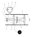
- the phase plate 1 is disposed in the beam path 2 of the TEM, in fact downstream of the sample 3. Specifically, the phase plate 1 is provided between the objective lens 4 and the image lens 5. A through hole 6 with a diameter of approx. 0.5 ⁇ m is made centrally in the phase plate (diameters are generally between 0.2 and 1 ⁇ m), through which electrons not scattered by the sample 3 can pass without any further interaction. However, the electrons scattered by the sample 3 are subjected to a phase shift upon passing through the phase plate 1, and this leads to an image with greater contrast due to interference with the unscattered electrons.
- a dry etching apparatus 8 is provided, pressure-fluidically connected to the examination chamber 7 of the TEM.
- a low pressure plasma is generated and corresponding electrodes 10 are arranged here (coils, for example, could also be provided as an alternative to electrodes).
- Oxygen is supplied here as the process gas, in fact oxygen from the ambient air (as an alternative, the gas from a specially attached pressure container could also be supplied).
- a needle valve 11 at the plasma chamber 9 is opened and the inflow is set such that the pressure present in the sample chamber 7 and the plasma chamber 9 is approximately 5x10 -4 mbar.
- the dry etching of the phase plate 1 takes place here before the first irradiation of the phase plate 1 with the electron beam, i.e. after the examination chamber 7 has been flooded and opened, the phase plate 1 has been inserted and evacuation to the intermediate pressure has taken place in the manner described above.
- the needle valve 11 is closed and the examination chamber 7 is evacuated further until there is a final pressure of approx. 10 -6 mbar. At this pressure the sample 3 can then be examined in the manner described above.
- Fig. 2 shows another embodiment which, as regards the structure of the TEM, corresponds to that of Fig. 1 .
- a vacuum sluice 21 is additionally provided by means of which the phase plate 1 can be introduced into the examination chamber 7.
- the outer sluicegate 23 is opened in order to introduce the phase plate 1 (the pressure in the sluice chamber corresponds to the ambient air pressure here).
- the sluice 21 is evacuated up to an intermediate pressure of approx. 5x10 -4 mbar.
- a vacuum pump 24 is connected pressure-fluidically to the latter.
- a dry etching apparatus 8 is provided, pressure-fluidically connected to the sluice 21, and a plasma is in turn generated between the electrodes 10.
- a needle valve 11 In order to supply oxygen as the process gas, there is in turn provided at the plasma chamber 9 of the dry etching apparatus 8 a needle valve 11 by means of which in this case oxygen is supplied from a pressure container (not shown). The supply is set here such that the intermediate pressure is approximately maintained.
- the dry etching apparatus 8 is deactivated for a period of approx. one hour, i.e. the field applied to the electrodes 10 is switched off. Likewise, the supply of oxygen is stopped and the sluice 21 is evacuated further, in fact up to a final pressure of approx. 10 -6 mbar.
- the inner sluicegate 22 Upon reaching this final pressure the inner sluicegate 22 is opened and the phase plate 1 is introduced into the (evacuated) examination chamber 7. Then the inner sluicegate 22 is closed again. The phase plate 1 is now available in the beam path of the TEM for the examination of a sample.
Landscapes
- Chemical & Material Sciences (AREA)
- Analytical Chemistry (AREA)
- Drying Of Semiconductors (AREA)
- Sampling And Sample Adjustment (AREA)
Abstract
Description
- The present invention relates to a phase plate, specifically to its use for a transmission electron microscope (TEM).
- This type of phase plate can be used, for example, when observing an organic, for example deep frozen specimen. In this type of application the image contrast may be comparatively small and a substantial part of the image information may be contained in a phase shift of the scattered electron beam. In attempts to make this phase shift visible in the image by means of defocusing, impairment of the resolution, for example, proved to be disadvantageous.
- Therefore, the most recent developments involve providing in the beam path of the TEM, downstream of the specimen, a phase plate, which subjects part of the electron beam to an additional phase shift. Therefore, for example, non-scattered electrons may pass through the phase plate without any further interaction, for example through a through hole in the phase plate, whereas the scattered electrons pass through the phase plate material and are accordingly subjected to an additional phase shift. The contrast in the image can thus be increased.
- The technical problem underlying the present invention is to specify a particularly advantageous method for cleaning a phase plate.
- According to the invention this object is achieved by a method wherein the phase plate is etched with an etching agent suitable for removing compounds containing oxygen and/or carbon, this etching taking place before the phase plate is irradiated for the first time in the TEM, and furthermore, after the etching, for the irradiation in the TEM, the phase plate being held in a holding atmosphere in which the portion of compounds containing oxygen and/or carbon is reduced.
- In this respect, in the case of the compounds containing oxygen, "reduced" means a concentration of at most 1x10¹¹/cm3, preferably at most 5x10¹⁰/cm3, more preferably at most 1x10¹⁰/cm3, and in the case of compounds containing carbon, a concentration of at most 5x10¹³/cm3, preferably at most 1x10¹³/cm3, more preferably at most 5x10¹²/cm3. Technically, in the case of the compounds containing oxygen, possible lower limits can be for example 1x10⁸/cm3 or 1x10⁹/cm3, and in the case of the compounds containing carbon for example 5x10¹⁰/cm3 or 5x10¹¹/cm3.
- The "compound containing oxygen" can for example also be the oxygen contained in the ambient air, and so the specified concentrations can relate, for example, to O2 molecules. The term "compound" is therefore to be understood as meaning chemical compounds, in particular molecules, and not the number of particles (a plurality of molecules can for example form a dust particle). Volatile organic hydrocarbons or dimethyl sulphate are examples of compounds containing carbon.
- These specified concentrations relate in this connection to molecules moving freely in the holding atmosphere or to molecules in freely moving compounds, i.e. not to elements limiting the volume containing the free-holding atmosphere - therefore, for example, a sealing ring sealing the examination chamber or an organic sample infiltrated into the examination chamber should (needless to say) not be taken into account when identifying the molecules containing carbon.
- In the "etching" of the phase plate, in principle it is not the phase plate material itself, but for example oxide compounds or carbon deposits on the surface, that should be removed. In this connection the inventors have found that surprisingly, satisfactory results can only be achieved by etching before the first irradiation. Therefore, if etching only takes place after the first irradiation (with electrons during an examination), according to the present situation more impurities are deposited and these are clearly harder to remove.
- Additional preferred embodiments are to be found in the dependent claims and the following description, no distinction being made between the presentation of the use and method aspects or the corresponding apparatus; the disclosure is to be understood, at least implicitly, with regard to all categories of claim.
- In one preferred configuration the holding atmosphere is a high vacuum, and so the pressure is at most 10-3 mbar, preferably at most 10-4 mbar, and more preferably at most 10-5 bar.
- In general, the "holding atmosphere" is the atmosphere present after the etching, i.e. immediately after the end of the etching process, in particular after removing the etching substances (i.e. the etching agent), and which is ideally present until the start of irradiation with electrons when examining a sample in the TEM. In this respect the holding atmosphere should therefore be present without interruption from after etching until irradiation (and generally also during the latter).
- Even though the holding atmosphere is, therefore, preferably a vacuum, in general a protective gas correspondingly largely free from compounds containing oxygen and/or carbon, for example, that would therefore have to be ultrapure, could also be provided for the holding of the phase plate, the "holding atmosphere" condition not being interrupted until the irradiation in the TEM.
- In a preferred configuration the phase plate is dry etched, generally for example also with argon as the process gas, i.e. mechanical particle removal. Preferably, etching is at least also chemical, i.e. an argon/hydrogen mixture, for example, can be provided.
- In general, the dry etching can also take place in at least two stages each with a different process gas or a different process gas mixture ratio, i.e. for example in a first step oxygen can be provided as the process gas, and in a second step hydrogen can be provided as the process gas; an additional process gas, for example argon, can in principle respectively also be present here.
- However, it is particularly preferable for oxygen to be the only process gas in a one-step process.
- Independently of the process gas in detail, in a preferred configuration, the dry etching takes place in the TEM, and generally this does not necessarily mean in the examination chamber itself, but at least in a part structurally connected to the latter, for example also detachable by means of a screw connection. For example, a sluice connected to the examination chamber by a sluice gate can therefore be provided, and the phase plate can be dry etched in this sluice. The phase plate (not yet irradiated) can therefore be introduced, for example, into the sluice, and the sluice can then be evacuated; before the phase plate is moved out of the sluice into the examination chamber it is dry etched, preferably at an intermediate pressure described in detail below. The sluice can then be further evacuated up to approximately the pressure in the examination chamber; after opening the (inner) sluicegate the phase plate can be moved into the examination chamber. The dry etching apparatus, in particular its electrode(s) or coil(s), is not necessarily disposed in the sluice itself here, but can also be provided as a dry etching chamber connected pressure-fluidically to the latter, for example connected by a valve which is then open during the dry etching. The supply of gas, and so the intermediate pressure, can be set by opening a valve, in particular a needle valve, which is preferably disposed at the dry etching chamber itself.
- Alternatively to the sluice, dry etching within the examination chamber of the TEM itself may also be preferred. The phase plate is mounted here in the TEM, i.e. the examination chamber is flooded, generally with ambient air, and opened, and is then disposed in the beam path. Next - before the first irradiation with electrons - the phase plate is dry etched in the examination chamber. In this connection the holding atmosphere is generally a high vacuum in the examination chamber.
- In a preferred configuration the examination chamber of the TEM is opened, the phase plate is inserted when the examination chamber is flooded, and the examination chamber is then evacuated again, preferably up to intermediate pressure. At this intermediate pressure the phase plate is then dry etched in the examination chamber. Finally, the examination chamber is evacuated further up to a final pressure which, measured in mbar, is smaller than the intermediate pressure by at least one order of magnitude. Thus, the etching of the phase plate can advantageously be integrated into the process of inserting the phase plate.
- Even though in this embodiment the phase plate is etched in the examination chamber, the dry etching apparatus itself does not necessarily have to be disposed in the examination chamber. A dry etching chamber connected pressure-fluidically to the examination chamber, in particular by means of a valve, is preferred.
- In general, the intermediate pressure can be for example at most 5x10⁻³ mbar, preferably at most 2.5x10⁻³ mbar, more preferably at most 1x10⁻³ mbar, and (independently of these upper limits) for example at least 5x10⁻⁵ mbar, preferably at least 7.5x10⁻⁵, more preferably at least 10-4 mbar. The final pressure can be for example at most 5x10⁻⁶ mbar, preferably at most 10-6 mbar; lower limits for the vacuum are given by what is possible technically in a vacuum. After inserting the phase plate, evacuation up to intermediate pressure takes place, particularly preferably directly, i.e. without previously reaching a lower pressure.
- In a preferred configuration, in order to provide the process gas, a gas containing oxygen, preferably ambient air, is supplied, metered, to the examination chamber in order to set the intermediate pressure of at most 5x10⁻³ mbar and at least 5x10⁻⁵ mbar (the values disclosed above as preferred for the intermediate pressure should also be disclosed in this connection). Generally, the gas is not supplied directly to the examination chamber here, but to a dry etching chamber (connected pressure-fluidically to the examination chamber) in which, for example, electrode(s) and/or coil(s) are also disposed. Generally, the gas can be supplied, for example, by opening a valve, in particular a needle valve; "metered" means, for example, that an adjustment can also be made. The vacuum pump(s), for example, is or are operated further, and the intermediate pressure is set by correspondingly opening the valve.
- In general, an etching rate of at least 0.05 nm/h is preferred for the etching of compounds containing oxygen and/or carbon, and a rate of at least 0.1 nm/h is more preferred and a rate of at least 0.15 nm/h is particularly preferred. Possible upper limits can be for example at most 600 nm/h, increasingly preferred in the sequence of at most 400 nm/h, 200 nm/h, 100 nm/h, 50 nm/h, 10 nm/h, 5 nm/h and 2.5 nm/h; one therefore then etches comparatively slowly.
- As already stated above, during etching ideally no phase plate material is removed, but in the case of dry etching with argon as the process gas for example, a certain degree of removal can nevertheless take place. In relation to the phase plate material the etching rate should however be no more than for example 0.01 nm/h, 0.005 nm/h or 0.001 nm/h.
- In general, the etching can last for example for at least 1 minute, preferably at least 10 minutes, more preferably at least 15 minutes, and at most (independently of these lower limits) at most 24 hours, preferably at most 6 hours, more preferably at most 3 hours.
- Additional preferred configurations relate to the properties of the phase plate itself, and the disclosure should explicitly also be understood as relating to a TEM with a corresponding phase plate. Preferably, the phase plate has at least a first layer of a first phase plate material that is made of a metal, preferably comprising chrome, particularly preferably being made of chrome. The first layer can have a thickness of, for example, at least 3 nm, increasingly preferably in this sequence of at least 3.5 nm, 4 nm, 4.5 nm or 5 nm; upper limits independent of these lower limits are for example at most 20 nm, increasingly preferably in the sequence of at most 18 nm, 16 nm, 14 nm, 12 nm, 11 nm or 10 nm (the "thickness" is taken perpendicularly to the surface directions of the phase plate).
- In a preferred configuration the phase plate has at least two layers (approximately 2, 3, 4 or 5 layers), one of the layers being made of silicon, preferably polysilicon. The thickness of this layer can be, for example, at least 3 nm, preferably at least 4 nm, more preferably at least 4.5 nm, and (independently of this lower limit) at most 30 nm, increasingly preferably in this sequence at most 25 nm, 20 nm, 15 nm, 10 nm, 7.5 nm or 6 nm.
- Therefore, a phase plate with a first layer, in fact a chrome layer which is provided over a second layer, namely a polysilicon layer, is particularly preferred. The chrome layer can be applied, for example, by vapour coating or sputtering.
- The invention also relates to a TEM that is designed for a method as described above and the phase plate is disposed in the beam path in the examination chamber of said TEM. Here the TEM further comprises a dry etching apparatus which is provided such that the phase plate can then be held in a holding atmosphere according to the definition given above. The dry etching apparatus, in particular electrodes for generating plasma, can also be provided in the examination chamber itself here, but is preferably disposed in a separate volume that is however connected pressure-fluidically to that of the examination chamber. In other words, the plasma is therefore not generated in the examination chamber itself, but radicals generated in the separate volume are supplied to the examination chamber.
- The invention also relates to the use of this type of TEM wherein the phase plate is held in the holding atmosphere until irradiation, and reference is explicitly made once again to the features disclosed above within the context of the method and which should explicitly also be disclosed with regard to the use.
- In the following the invention is described in more detail by means of an exemplary embodiment, no detailed distinction being made, furthermore, between the different categories of claim.
- Fig. 1
- shows a diagrammatic illustration of a TEM with a phase plate which is dry etched in the examination chamber;
- Fig. 2
- shows diagrammatically a TEM with a phase plate which is dry etched in a sluice of the TEM.
- As shown in
Fig. 1 , thephase plate 1 is disposed in thebeam path 2 of the TEM, in fact downstream of thesample 3. Specifically, thephase plate 1 is provided between theobjective lens 4 and theimage lens 5. A throughhole 6 with a diameter of approx. 0.5 µm is made centrally in the phase plate (diameters are generally between 0.2 and 1 µm), through which electrons not scattered by thesample 3 can pass without any further interaction. However, the electrons scattered by thesample 3 are subjected to a phase shift upon passing through thephase plate 1, and this leads to an image with greater contrast due to interference with the unscattered electrons. - A
dry etching apparatus 8 is provided, pressure-fluidically connected to theexamination chamber 7 of the TEM. In theplasma chamber 9 of said dry etching apparatus 8 a low pressure plasma is generated andcorresponding electrodes 10 are arranged here (coils, for example, could also be provided as an alternative to electrodes). Oxygen is supplied here as the process gas, in fact oxygen from the ambient air (as an alternative, the gas from a specially attached pressure container could also be supplied). For this purpose aneedle valve 11 at theplasma chamber 9 is opened and the inflow is set such that the pressure present in thesample chamber 7 and theplasma chamber 9 is approximately 5x10⁻⁴ mbar. - The dry etching of the
phase plate 1 takes place here before the first irradiation of thephase plate 1 with the electron beam, i.e. after theexamination chamber 7 has been flooded and opened, thephase plate 1 has been inserted and evacuation to the intermediate pressure has taken place in the manner described above. - After the etching the
needle valve 11 is closed and theexamination chamber 7 is evacuated further until there is a final pressure of approx. 10-6 mbar. At this pressure thesample 3 can then be examined in the manner described above. -
Fig. 2 shows another embodiment which, as regards the structure of the TEM, corresponds to that ofFig. 1 . In this case, however, avacuum sluice 21 is additionally provided by means of which thephase plate 1 can be introduced into theexamination chamber 7. For this purpose, when theinner sluicegate 22 is closed with respect to theexamination chamber 7, theouter sluicegate 23 is opened in order to introduce the phase plate 1 (the pressure in the sluice chamber corresponds to the ambient air pressure here). After introducing thephase plate 1 and closing theouter sluicegate 23, thesluice 21 is evacuated up to an intermediate pressure of approx. 5x10⁻⁴ mbar. In order to evacuate thesluice 21, avacuum pump 24 is connected pressure-fluidically to the latter. - A
dry etching apparatus 8 is provided, pressure-fluidically connected to thesluice 21, and a plasma is in turn generated between theelectrodes 10. In order to supply oxygen as the process gas, there is in turn provided at theplasma chamber 9 of the dry etching apparatus 8 aneedle valve 11 by means of which in this case oxygen is supplied from a pressure container (not shown). The supply is set here such that the intermediate pressure is approximately maintained. - After the etching of the
phase plate 1 in thesluice chamber 21 thedry etching apparatus 8 is deactivated for a period of approx. one hour, i.e. the field applied to theelectrodes 10 is switched off. Likewise, the supply of oxygen is stopped and thesluice 21 is evacuated further, in fact up to a final pressure of approx. 10-6 mbar. - Upon reaching this final pressure the
inner sluicegate 22 is opened and thephase plate 1 is introduced into the (evacuated)examination chamber 7. Then theinner sluicegate 22 is closed again. Thephase plate 1 is now available in the beam path of the TEM for the examination of a sample.
Claims (16)
- A method for cleaning a phase plate (1) which is designed to be disposed and irradiated in an examination chamber (7) in the beam path (2) of a transmission electron microscope (TEM),
said phase plate (1) being etched with an etching agent that is suitable for removing a compound that contains at least one of oxygen and carbon,
said etching taking place before said phase plate (1) is irradiated for the first time in said TEM,
and furthermore, after said etching, said phase plate (1) being held for said irradiation in said TEM in a holding atmosphere in which the portion of at least one of compounds containing oxygen and compounds containing carbon is reduced, which for said compounds containing oxygen means a molecule concentration of at most 1·1011/cm3, and for said compounds containing carbon means a molecule concentration of at most 5·1013/cm3. - The method according to Claim 1, wherein said holding atmosphere is a high vacuum.
- The method according to Claim 1 or 2, wherein said phase plate (1) is etched and said etching is dry etching, preferably at least also chemical dry etching.
- The method according to Claim 3, wherein said drying etching takes place in said TEM.
- The method according to Claim 4, wherein said dry etching takes place in a sluice (21) added to said examination chamber (7) of said TEM, which sluice (21) can be connected pressure-fluidically to said examination chamber (7) by opening an inner sluicegate (22), said etching taking place when said inner sluicegate (22) is closed.
- The method according to Claim 5, wherein when said inner sluicegate (22) is closed, said phase plate (1) is introduced into said sluice (21) through an outer sluicegate (23), said outer sluicegate (23) is then closed, and said sluice (21) is evacuated to an intermediate pressure at which said dry etching then takes place, further evacuation then taking place up to a final pressure which is lower than said intermediate pressure by at least a factor of 10, and said inner sluicegate (22) then being opened, and said phase plate (1) being introduced into said examination chamber (7).
- The method according to Claim 4, wherein said dry etching takes place in said examination chamber (7) of said TEM.
- The method according to Claim 7, wherein said examination chamber (7) of said TEM is opened, when said examination chamber (7) is flooded said phase plate (1) is inserted, and said examination chamber (7) is then evacuated up to an intermediate pressure at which said dry etching then takes place, evacuation then taking place to a final pressure which is lower than said intermediate pressure by at least a factor of 10.
- The method according to any of Claims 3 to 8, wherein a process gas provided for said dry etching comprises at least one of hydrogen and oxygen.
- The method according to Claim 9, wherein a gas containing oxygen, preferably ambient air, is supplied, metered, to said sluice (21) in combination with Claim 6, or in combination with Claim 8 is supplied to said examination chamber (7), in order to set an intermediate pressure of at most 5·10-3 mbar and at least 5·10-5 mbar and to dry etch with oxygen as the process gas.
- The method according to any of the preceding claims, wherein said phase plate (1) is etched and said etching agent has an etching rate of at least 0.05 nm/h in relation to said compound containing at least one of oxygen and carbon.
- The method according to any of the preceding claims, wherein said phase plate (1) has at least a first layer of a first phase plate material that is made of a metal, preferably chrome.
- The method according to any of the preceding claims, wherein said phase plate (1) has at least a first layer of a first phase plate material and a second layer of a second phase plate material, which second phase plate material is made of silicon, preferably polysilicon.
- A transmission electron microscope, designed for a method according to any of Claims 1 to 13, comprising
an examination chamber (7) and
a phase plate (1) which is disposed in said beam path in said examination chamber (7) of said transmission electron microscope,
said transmission electron microscope further comprising a dry etching apparatus by means of which said phase plate (1) can be etched with said etching agent, said dry etching apparatus (8) being provided such that after said etching, said phase plate (1) can be held in said holding atmosphere until said irradiation in said TEM. - A use of a TEM according to Claim 14, wherein said phase plate (1) is etched with an etching agent that is suitable for removing a compound that comprises at least one of oxygen and carbon, said etching taking place before said phase plate (1) is irradiated for the first time in said TEM, and said phase plate (1) being held after said etching until said irradiation in said TEM in a holding atmosphere in which the portion of at least one of molecules containing oxygen and compounds containing carbon is reduced, which for said compounds containing oxygen means a molecule concentration of at most 1·1011/cm3 and for said compounds containing carbon a molecule concentration of at most 5·1013/cm3.
- The use according to Claim 15 according to a method according to any of Claims 1 to 13.
Applications Claiming Priority (1)
| Application Number | Priority Date | Filing Date | Title |
|---|---|---|---|
| DE102013019297.8A DE102013019297A1 (en) | 2013-11-19 | 2013-11-19 | Phase plate for a transmission electron microscope |
Publications (2)
| Publication Number | Publication Date |
|---|---|
| EP2879158A1 true EP2879158A1 (en) | 2015-06-03 |
| EP2879158B1 EP2879158B1 (en) | 2016-08-24 |
Family
ID=51900800
Family Applications (1)
| Application Number | Title | Priority Date | Filing Date |
|---|---|---|---|
| EP14193565.0A Active EP2879158B1 (en) | 2013-11-19 | 2014-11-18 | Phase plate for a transmission electron microscope |
Country Status (5)
| Country | Link |
|---|---|
| US (1) | US9460890B2 (en) |
| EP (1) | EP2879158B1 (en) |
| JP (1) | JP6291403B2 (en) |
| CN (1) | CN104681383B (en) |
| DE (1) | DE102013019297A1 (en) |
Families Citing this family (1)
| Publication number | Priority date | Publication date | Assignee | Title |
|---|---|---|---|---|
| EP2881970A1 (en) | 2013-12-04 | 2015-06-10 | Fei Company | Method of producing a freestanding thin film of nano-crystalline carbon |
Citations (2)
| Publication number | Priority date | Publication date | Assignee | Title |
|---|---|---|---|---|
| EP1845551A1 (en) * | 2004-12-03 | 2007-10-17 | Inter-University Research Institute Corporation NA | Phase plate for phase-contrast electron microscope, method for manufacturing the same and phase-contrast electron microscope |
| US20120037815A1 (en) * | 2010-08-16 | 2012-02-16 | Yunn-Shin Shiue | Tem phase plate loading system |
Family Cites Families (40)
| Publication number | Priority date | Publication date | Assignee | Title |
|---|---|---|---|---|
| US3908124A (en) | 1974-07-01 | 1975-09-23 | Us Energy | Phase contrast in high resolution electron microscopy |
| JPS607048A (en) | 1983-06-24 | 1985-01-14 | Hitachi Ltd | Phase-contrast electron microscope |
| US4665315A (en) | 1985-04-01 | 1987-05-12 | Control Data Corporation | Method and apparatus for in-situ plasma cleaning of electron beam optical systems |
| US5633502A (en) * | 1995-08-11 | 1997-05-27 | E. A. Fischione Instruments, Inc. | Plasma processing system for transmission electron microscopy specimens and specimen holders |
| US5510624A (en) | 1995-09-01 | 1996-04-23 | The University Of Chicago | Simultaneous specimen and stage cleaning device for analytical electron microscope |
| US5814815A (en) | 1995-12-27 | 1998-09-29 | Hitachi, Ltd. | Phase-contrast electron microscope and phase plate therefor |
| JP2000268765A (en) | 1999-03-16 | 2000-09-29 | Jeol Ltd | Transmission electron microscope |
| JP2001084938A (en) | 1999-09-13 | 2001-03-30 | Hitachi Ltd | Transmission electron microscope and transmission electron microscope image observation method |
| US6452315B1 (en) | 2000-02-08 | 2002-09-17 | Ronald A. Vane | Compact RF plasma device for cleaning electron microscopes and vacuum chambers |
| JP3773389B2 (en) | 2000-03-27 | 2006-05-10 | 日本電子株式会社 | Thin film phase plate for phase contrast electron microscope, phase contrast electron microscope and phase plate antistatic method |
| JP3942363B2 (en) * | 2001-02-09 | 2007-07-11 | 日本電子株式会社 | Lens system for phase plate of transmission electron microscope and transmission electron microscope |
| US6548810B2 (en) | 2001-08-01 | 2003-04-15 | The University Of Chicago | Scanning confocal electron microscope |
| JP4328044B2 (en) | 2001-09-25 | 2009-09-09 | 日本電子株式会社 | Differential contrast electron microscope and data processing method of electron microscope image |
| DE10200645A1 (en) | 2002-01-10 | 2003-07-24 | Leo Elektronenmikroskopie Gmbh | Electron microscope with circular illumination aperture |
| DE10206703A1 (en) | 2002-02-18 | 2003-08-28 | Max Planck Gesellschaft | Phase plate for electron microscopy and electron microscopic imaging |
| DE10313644A1 (en) | 2003-03-26 | 2004-10-07 | Leica Microsystems Semiconductor Gmbh | Device and method for reducing the electron beam-induced deposition of contamination products |
| JP2005116365A (en) | 2003-10-08 | 2005-04-28 | Jeol Ltd | Transmission electron microscope with phase plate and phase plate lens system |
| JP2006012795A (en) * | 2004-05-21 | 2006-01-12 | Kyoto Univ | Transmission electron microscope |
| US7737412B2 (en) * | 2004-07-12 | 2010-06-15 | The Regents Of The University Of California | Electron microscope phase enhancement |
| US8212225B2 (en) * | 2005-05-13 | 2012-07-03 | State Of Oregon Acting By And Through The State Board Of Higher Education On Behalf Of The University Of Oregon | TEM grids for determination of structure-property relationships in nanotechnology |
| DE102005040267B4 (en) | 2005-08-24 | 2007-12-27 | Universität Karlsruhe | Method for producing a multilayer electrostatic lens arrangement, in particular a phase plate and such a phase plate |
| EP1950789A4 (en) | 2005-11-04 | 2011-05-11 | Nagayama Ip Holdings Llc | Phase plate for electron microscope, and its manufacturing method |
| US20090166558A1 (en) | 2005-11-15 | 2009-07-02 | Kuniaki Nagayama | Phase Contrast Electron Microscope Device |
| DE102006011615A1 (en) * | 2006-03-14 | 2007-09-20 | Carl Zeiss Nts Gmbh | Phase contrast electron microscope |
| DE102006055510B4 (en) | 2006-11-24 | 2009-05-07 | Ceos Corrected Electron Optical Systems Gmbh | Phase plate, image forming method and electron microscope |
| DE102007007923A1 (en) | 2007-02-14 | 2008-08-21 | Carl Zeiss Nts Gmbh | Phase-shifting element and particle beam device with phase-shifting element |
| EP2091062A1 (en) | 2008-02-13 | 2009-08-19 | FEI Company | TEM with aberration corrector and phase plate |
| GB0805819D0 (en) | 2008-03-31 | 2008-04-30 | Edgecombe Christopher | Phase plate for electron microscope |
| EP2131385A1 (en) | 2008-06-05 | 2009-12-09 | FEI Company | Hybrid phase plate |
| US7977633B2 (en) | 2008-08-27 | 2011-07-12 | Max-Planck-Gesellschaft Zur Foerderung Der Wissenschaften E. V. | Phase plate, in particular for an electron microscope |
| TWI449442B (en) | 2009-01-14 | 2014-08-11 | Dolby Lab Licensing Corp | Method and system for frequency domain active matrix decoding without feedback |
| WO2011071819A1 (en) | 2009-12-07 | 2011-06-16 | Regents Of The University Of California | Optical-cavity phase plate for transmission electron microscopy |
| EP2400522A1 (en) | 2010-06-24 | 2011-12-28 | Fei Company | Blocking member for use in the diffraction plane of a TEM |
| EP2485239A1 (en) | 2011-02-07 | 2012-08-08 | FEI Company | Method for centering an optical element in a TEM comprising a contrast enhancing element |
| JP5745957B2 (en) * | 2011-07-01 | 2015-07-08 | 株式会社日立ハイテクノロジーズ | Phase plate and electron microscope |
| US8716676B2 (en) * | 2011-08-04 | 2014-05-06 | Xei Scientific, Inc. | Device to load TEM sample holders into a vacuum chamber |
| JP2013174746A (en) * | 2012-02-24 | 2013-09-05 | National Institutes Of Natural Sciences | Phase plate device, method for manufacturing the same, and phase difference electron microscope |
| EP2667399A1 (en) | 2012-05-23 | 2013-11-27 | FEI Company | Improved phase plate for a TEM |
| EP2704178B1 (en) | 2012-08-30 | 2014-08-20 | Fei Company | Imaging a sample in a TEM equipped with a phase plate |
| JP6286270B2 (en) * | 2013-04-25 | 2018-02-28 | エフ イー アイ カンパニFei Company | Method using a phase plate in a transmission electron microscope |
-
2013
- 2013-11-19 DE DE102013019297.8A patent/DE102013019297A1/en not_active Withdrawn
-
2014
- 2014-11-17 JP JP2014232448A patent/JP6291403B2/en active Active
- 2014-11-18 EP EP14193565.0A patent/EP2879158B1/en active Active
- 2014-11-19 US US14/548,077 patent/US9460890B2/en active Active
- 2014-11-19 CN CN201410660475.3A patent/CN104681383B/en active Active
Patent Citations (2)
| Publication number | Priority date | Publication date | Assignee | Title |
|---|---|---|---|---|
| EP1845551A1 (en) * | 2004-12-03 | 2007-10-17 | Inter-University Research Institute Corporation NA | Phase plate for phase-contrast electron microscope, method for manufacturing the same and phase-contrast electron microscope |
| US20120037815A1 (en) * | 2010-08-16 | 2012-02-16 | Yunn-Shin Shiue | Tem phase plate loading system |
Non-Patent Citations (3)
| Title |
|---|
| IDZOREK G ET AL: "Reproducible, rugged, and inexpensive photocathode x-ray diode", REVIEW OF SCIENTIFIC INSTRUMENTS, AIP, MELVILLE, NY, US, vol. 79, no. 10, 31 October 2008 (2008-10-31), pages 10E922 - 10E922, XP012114774, ISSN: 0034-6748, DOI: 10.1063/1.2969279 * |
| MICHAEL MARKO ET AL: "Retrofit implementation of Zernike phase plate imaging for cryo-TEM", JOURNAL OF STRUCTURAL BIOLOGY, ACADEMIC PRESS, UNITED STATES, vol. 174, no. 2, 19 January 2011 (2011-01-19), pages 400 - 412, XP028190316, ISSN: 1047-8477, [retrieved on 20110125], DOI: 10.1016/J.JSB.2011.01.005 * |
| MÜLLER H ET AL: "Design of an electron microscope phase plate using a focused continuous-wave laser;Design of an electron microscope phase plate using a focused continuous-wave laser", NEW JOURNAL OF PHYSICS, INSTITUTE OF PHYSICS PUBLISHING, BRISTOL, GB, vol. 12, no. 7, 12 July 2010 (2010-07-12), pages 73011, XP020194658, ISSN: 1367-2630, DOI: 10.1088/1367-2630/12/7/073011 * |
Also Published As
| Publication number | Publication date |
|---|---|
| US9460890B2 (en) | 2016-10-04 |
| CN104681383A (en) | 2015-06-03 |
| DE102013019297A1 (en) | 2015-05-21 |
| US20150136172A1 (en) | 2015-05-21 |
| JP2015099778A (en) | 2015-05-28 |
| EP2879158B1 (en) | 2016-08-24 |
| JP6291403B2 (en) | 2018-03-14 |
| CN104681383B (en) | 2018-04-13 |
Similar Documents
| Publication | Publication Date | Title |
|---|---|---|
| US8349125B2 (en) | Cleaning device for transmission electron microscopes | |
| US6268608B1 (en) | Method and apparatus for selective in-situ etching of inter dielectric layers | |
| US5510624A (en) | Simultaneous specimen and stage cleaning device for analytical electron microscope | |
| KR102203973B1 (en) | Method and device for the surface treatment of substrates | |
| JP5918823B2 (en) | Electron microscope plasma cleaner and electron microscope cleaning method | |
| Leuthner et al. | Scanning transmission electron microscopy under controlled low-pressure atmospheres | |
| US8507879B2 (en) | Oxidative cleaning method and apparatus for electron microscopes using UV excitation in an oxygen radical source | |
| JP2011034895A (en) | Charged particle beam device and sample decontamination mechanism | |
| JP2007207758A (en) | Particle optical device having a predetermined final vacuum pressure | |
| US11668309B2 (en) | Vacuum component and evacuation method using the same | |
| Vladár et al. | Active monitoring and control of electron-beam-induced contamination | |
| Figueiredo et al. | Influence of ion induced secondary electron emission on the stability of ionisation vacuum gauges | |
| JP2007172862A (en) | Cleaning device for charged particle beam source and charged particle beam device using the same | |
| JP2002025497A (en) | Vacuum analyzer, mass analyzer, and electron microscope | |
| EP2879158B1 (en) | Phase plate for a transmission electron microscope | |
| EP1048071B1 (en) | Integrated circuit rewiring using gas-assisted focused ion beam (fib) etching | |
| Wanzenboeck et al. | Novel method for cleaning a vacuum chamber from hydrocarbon contamination | |
| US20070284541A1 (en) | Oxidative cleaning method and apparatus for electron microscopes using UV excitation in a oxygen radical source | |
| Holland | Substrate treatment and film deposition in ionized and activated gas | |
| Krivanek et al. | Atomic-resolution STEM at low primary energies | |
| JP2001325912A (en) | Electron beam inspection equipment | |
| JPH11329328A (en) | Electron beam inspection equipment | |
| JP2000149844A (en) | Electron beam inspection equipment | |
| Nagata et al. | Effect of annealing on implanted Ga of diamond-like carbon thin films fabricated by focused-ion-beam chemical vapor deposition | |
| JP2010281710A (en) | Method and apparatus for measuring electron spectrum |
Legal Events
| Date | Code | Title | Description |
|---|---|---|---|
| PUAI | Public reference made under article 153(3) epc to a published international application that has entered the european phase |
Free format text: ORIGINAL CODE: 0009012 |
|
| 17P | Request for examination filed |
Effective date: 20141118 |
|
| AK | Designated contracting states |
Kind code of ref document: A1 Designated state(s): AL AT BE BG CH CY CZ DE DK EE ES FI FR GB GR HR HU IE IS IT LI LT LU LV MC MK MT NL NO PL PT RO RS SE SI SK SM TR |
|
| AX | Request for extension of the european patent |
Extension state: BA ME |
|
| R17P | Request for examination filed (corrected) |
Effective date: 20151130 |
|
| RBV | Designated contracting states (corrected) |
Designated state(s): AL AT BE BG CH CY CZ DE DK EE ES FI FR GB GR HR HU IE IS IT LI LT LU LV MC MK MT NL NO PL PT RO RS SE SI SK SM TR |
|
| GRAP | Despatch of communication of intention to grant a patent |
Free format text: ORIGINAL CODE: EPIDOSNIGR1 |
|
| INTG | Intention to grant announced |
Effective date: 20160518 |
|
| GRAS | Grant fee paid |
Free format text: ORIGINAL CODE: EPIDOSNIGR3 |
|
| GRAA | (expected) grant |
Free format text: ORIGINAL CODE: 0009210 |
|
| AK | Designated contracting states |
Kind code of ref document: B1 Designated state(s): AL AT BE BG CH CY CZ DE DK EE ES FI FR GB GR HR HU IE IS IT LI LT LU LV MC MK MT NL NO PL PT RO RS SE SI SK SM TR |
|
| REG | Reference to a national code |
Ref country code: GB Ref legal event code: FG4D |
|
| REG | Reference to a national code |
Ref country code: CH Ref legal event code: EP |
|
| REG | Reference to a national code |
Ref country code: AT Ref legal event code: REF Ref document number: 823740 Country of ref document: AT Kind code of ref document: T Effective date: 20160915 |
|
| REG | Reference to a national code |
Ref country code: IE Ref legal event code: FG4D |
|
| REG | Reference to a national code |
Ref country code: DE Ref legal event code: R096 Ref document number: 602014003254 Country of ref document: DE |
|
| REG | Reference to a national code |
Ref country code: FR Ref legal event code: PLFP Year of fee payment: 3 |
|
| REG | Reference to a national code |
Ref country code: LT Ref legal event code: MG4D |
|
| REG | Reference to a national code |
Ref country code: NL Ref legal event code: MP Effective date: 20160824 |
|
| REG | Reference to a national code |
Ref country code: AT Ref legal event code: MK05 Ref document number: 823740 Country of ref document: AT Kind code of ref document: T Effective date: 20160824 |
|
| PG25 | Lapsed in a contracting state [announced via postgrant information from national office to epo] |
Ref country code: NO Free format text: LAPSE BECAUSE OF FAILURE TO SUBMIT A TRANSLATION OF THE DESCRIPTION OR TO PAY THE FEE WITHIN THE PRESCRIBED TIME-LIMIT Effective date: 20161124 Ref country code: NL Free format text: LAPSE BECAUSE OF FAILURE TO SUBMIT A TRANSLATION OF THE DESCRIPTION OR TO PAY THE FEE WITHIN THE PRESCRIBED TIME-LIMIT Effective date: 20160824 Ref country code: RS Free format text: LAPSE BECAUSE OF FAILURE TO SUBMIT A TRANSLATION OF THE DESCRIPTION OR TO PAY THE FEE WITHIN THE PRESCRIBED TIME-LIMIT Effective date: 20160824 Ref country code: IT Free format text: LAPSE BECAUSE OF FAILURE TO SUBMIT A TRANSLATION OF THE DESCRIPTION OR TO PAY THE FEE WITHIN THE PRESCRIBED TIME-LIMIT Effective date: 20160824 Ref country code: HR Free format text: LAPSE BECAUSE OF FAILURE TO SUBMIT A TRANSLATION OF THE DESCRIPTION OR TO PAY THE FEE WITHIN THE PRESCRIBED TIME-LIMIT Effective date: 20160824 Ref country code: LT Free format text: LAPSE BECAUSE OF FAILURE TO SUBMIT A TRANSLATION OF THE DESCRIPTION OR TO PAY THE FEE WITHIN THE PRESCRIBED TIME-LIMIT Effective date: 20160824 Ref country code: FI Free format text: LAPSE BECAUSE OF FAILURE TO SUBMIT A TRANSLATION OF THE DESCRIPTION OR TO PAY THE FEE WITHIN THE PRESCRIBED TIME-LIMIT Effective date: 20160824 |
|
| PG25 | Lapsed in a contracting state [announced via postgrant information from national office to epo] |
Ref country code: LV Free format text: LAPSE BECAUSE OF FAILURE TO SUBMIT A TRANSLATION OF THE DESCRIPTION OR TO PAY THE FEE WITHIN THE PRESCRIBED TIME-LIMIT Effective date: 20160824 Ref country code: ES Free format text: LAPSE BECAUSE OF FAILURE TO SUBMIT A TRANSLATION OF THE DESCRIPTION OR TO PAY THE FEE WITHIN THE PRESCRIBED TIME-LIMIT Effective date: 20160824 Ref country code: BE Free format text: LAPSE BECAUSE OF NON-PAYMENT OF DUE FEES Effective date: 20161130 Ref country code: PT Free format text: LAPSE BECAUSE OF FAILURE TO SUBMIT A TRANSLATION OF THE DESCRIPTION OR TO PAY THE FEE WITHIN THE PRESCRIBED TIME-LIMIT Effective date: 20161226 Ref country code: GR Free format text: LAPSE BECAUSE OF FAILURE TO SUBMIT A TRANSLATION OF THE DESCRIPTION OR TO PAY THE FEE WITHIN THE PRESCRIBED TIME-LIMIT Effective date: 20161125 Ref country code: SE Free format text: LAPSE BECAUSE OF FAILURE TO SUBMIT A TRANSLATION OF THE DESCRIPTION OR TO PAY THE FEE WITHIN THE PRESCRIBED TIME-LIMIT Effective date: 20160824 Ref country code: AT Free format text: LAPSE BECAUSE OF FAILURE TO SUBMIT A TRANSLATION OF THE DESCRIPTION OR TO PAY THE FEE WITHIN THE PRESCRIBED TIME-LIMIT Effective date: 20160824 |
|
| PG25 | Lapsed in a contracting state [announced via postgrant information from national office to epo] |
Ref country code: EE Free format text: LAPSE BECAUSE OF FAILURE TO SUBMIT A TRANSLATION OF THE DESCRIPTION OR TO PAY THE FEE WITHIN THE PRESCRIBED TIME-LIMIT Effective date: 20160824 Ref country code: RO Free format text: LAPSE BECAUSE OF FAILURE TO SUBMIT A TRANSLATION OF THE DESCRIPTION OR TO PAY THE FEE WITHIN THE PRESCRIBED TIME-LIMIT Effective date: 20160824 |
|
| REG | Reference to a national code |
Ref country code: DE Ref legal event code: R097 Ref document number: 602014003254 Country of ref document: DE |
|
| PG25 | Lapsed in a contracting state [announced via postgrant information from national office to epo] |
Ref country code: BE Free format text: LAPSE BECAUSE OF FAILURE TO SUBMIT A TRANSLATION OF THE DESCRIPTION OR TO PAY THE FEE WITHIN THE PRESCRIBED TIME-LIMIT Effective date: 20160824 Ref country code: SK Free format text: LAPSE BECAUSE OF FAILURE TO SUBMIT A TRANSLATION OF THE DESCRIPTION OR TO PAY THE FEE WITHIN THE PRESCRIBED TIME-LIMIT Effective date: 20160824 Ref country code: PL Free format text: LAPSE BECAUSE OF FAILURE TO SUBMIT A TRANSLATION OF THE DESCRIPTION OR TO PAY THE FEE WITHIN THE PRESCRIBED TIME-LIMIT Effective date: 20160824 Ref country code: SM Free format text: LAPSE BECAUSE OF FAILURE TO SUBMIT A TRANSLATION OF THE DESCRIPTION OR TO PAY THE FEE WITHIN THE PRESCRIBED TIME-LIMIT Effective date: 20160824 Ref country code: CZ Free format text: LAPSE BECAUSE OF FAILURE TO SUBMIT A TRANSLATION OF THE DESCRIPTION OR TO PAY THE FEE WITHIN THE PRESCRIBED TIME-LIMIT Effective date: 20160824 Ref country code: DK Free format text: LAPSE BECAUSE OF FAILURE TO SUBMIT A TRANSLATION OF THE DESCRIPTION OR TO PAY THE FEE WITHIN THE PRESCRIBED TIME-LIMIT Effective date: 20160824 Ref country code: BG Free format text: LAPSE BECAUSE OF FAILURE TO SUBMIT A TRANSLATION OF THE DESCRIPTION OR TO PAY THE FEE WITHIN THE PRESCRIBED TIME-LIMIT Effective date: 20161124 |
|
| PLBE | No opposition filed within time limit |
Free format text: ORIGINAL CODE: 0009261 |
|
| STAA | Information on the status of an ep patent application or granted ep patent |
Free format text: STATUS: NO OPPOSITION FILED WITHIN TIME LIMIT |
|
| 26N | No opposition filed |
Effective date: 20170526 |
|
| REG | Reference to a national code |
Ref country code: IE Ref legal event code: MM4A |
|
| PG25 | Lapsed in a contracting state [announced via postgrant information from national office to epo] |
Ref country code: SI Free format text: LAPSE BECAUSE OF FAILURE TO SUBMIT A TRANSLATION OF THE DESCRIPTION OR TO PAY THE FEE WITHIN THE PRESCRIBED TIME-LIMIT Effective date: 20160824 |
|
| PG25 | Lapsed in a contracting state [announced via postgrant information from national office to epo] |
Ref country code: LU Free format text: LAPSE BECAUSE OF NON-PAYMENT OF DUE FEES Effective date: 20161130 |
|
| REG | Reference to a national code |
Ref country code: FR Ref legal event code: PLFP Year of fee payment: 4 |
|
| PG25 | Lapsed in a contracting state [announced via postgrant information from national office to epo] |
Ref country code: IE Free format text: LAPSE BECAUSE OF NON-PAYMENT OF DUE FEES Effective date: 20161118 |
|
| PG25 | Lapsed in a contracting state [announced via postgrant information from national office to epo] |
Ref country code: HU Free format text: LAPSE BECAUSE OF FAILURE TO SUBMIT A TRANSLATION OF THE DESCRIPTION OR TO PAY THE FEE WITHIN THE PRESCRIBED TIME-LIMIT; INVALID AB INITIO Effective date: 20141118 |
|
| PG25 | Lapsed in a contracting state [announced via postgrant information from national office to epo] |
Ref country code: MC Free format text: LAPSE BECAUSE OF FAILURE TO SUBMIT A TRANSLATION OF THE DESCRIPTION OR TO PAY THE FEE WITHIN THE PRESCRIBED TIME-LIMIT Effective date: 20160824 Ref country code: MK Free format text: LAPSE BECAUSE OF FAILURE TO SUBMIT A TRANSLATION OF THE DESCRIPTION OR TO PAY THE FEE WITHIN THE PRESCRIBED TIME-LIMIT Effective date: 20160824 Ref country code: IS Free format text: LAPSE BECAUSE OF FAILURE TO SUBMIT A TRANSLATION OF THE DESCRIPTION OR TO PAY THE FEE WITHIN THE PRESCRIBED TIME-LIMIT Effective date: 20160824 Ref country code: CY Free format text: LAPSE BECAUSE OF FAILURE TO SUBMIT A TRANSLATION OF THE DESCRIPTION OR TO PAY THE FEE WITHIN THE PRESCRIBED TIME-LIMIT Effective date: 20160824 |
|
| PG25 | Lapsed in a contracting state [announced via postgrant information from national office to epo] |
Ref country code: CH Free format text: LAPSE BECAUSE OF NON-PAYMENT OF DUE FEES Effective date: 20171130 Ref country code: LI Free format text: LAPSE BECAUSE OF NON-PAYMENT OF DUE FEES Effective date: 20171130 |
|
| PG25 | Lapsed in a contracting state [announced via postgrant information from national office to epo] |
Ref country code: MT Free format text: LAPSE BECAUSE OF NON-PAYMENT OF DUE FEES Effective date: 20161118 |
|
| REG | Reference to a national code |
Ref country code: FR Ref legal event code: PLFP Year of fee payment: 5 |
|
| PG25 | Lapsed in a contracting state [announced via postgrant information from national office to epo] |
Ref country code: AL Free format text: LAPSE BECAUSE OF FAILURE TO SUBMIT A TRANSLATION OF THE DESCRIPTION OR TO PAY THE FEE WITHIN THE PRESCRIBED TIME-LIMIT Effective date: 20160824 Ref country code: TR Free format text: LAPSE BECAUSE OF FAILURE TO SUBMIT A TRANSLATION OF THE DESCRIPTION OR TO PAY THE FEE WITHIN THE PRESCRIBED TIME-LIMIT Effective date: 20160824 |
|
| P01 | Opt-out of the competence of the unified patent court (upc) registered |
Effective date: 20230524 |
|
| PGFP | Annual fee paid to national office [announced via postgrant information from national office to epo] |
Ref country code: DE Payment date: 20251010 Year of fee payment: 12 |
|
| PGFP | Annual fee paid to national office [announced via postgrant information from national office to epo] |
Ref country code: GB Payment date: 20251114 Year of fee payment: 12 |
|
| PGFP | Annual fee paid to national office [announced via postgrant information from national office to epo] |
Ref country code: FR Payment date: 20251111 Year of fee payment: 12 |