EP2879007A1 - Portable device with built-in antenna - Google Patents
Portable device with built-in antenna Download PDFInfo
- Publication number
- EP2879007A1 EP2879007A1 EP14189494.9A EP14189494A EP2879007A1 EP 2879007 A1 EP2879007 A1 EP 2879007A1 EP 14189494 A EP14189494 A EP 14189494A EP 2879007 A1 EP2879007 A1 EP 2879007A1
- Authority
- EP
- European Patent Office
- Prior art keywords
- antenna
- bezel
- portable device
- main body
- armor case
- Prior art date
- Legal status (The legal status is an assumption and is not a legal conclusion. Google has not performed a legal analysis and makes no representation as to the accuracy of the status listed.)
- Withdrawn
Links
- 230000005855 radiation Effects 0.000 claims abstract description 51
- 229910052751 metal Inorganic materials 0.000 claims abstract description 30
- 239000002184 metal Substances 0.000 claims abstract description 30
- 210000000707 wrist Anatomy 0.000 abstract description 51
- 239000011521 glass Substances 0.000 abstract description 26
- 125000006850 spacer group Chemical group 0.000 description 20
- 239000004973 liquid crystal related substance Substances 0.000 description 17
- 230000035945 sensitivity Effects 0.000 description 13
- 239000004033 plastic Substances 0.000 description 9
- 229920003023 plastic Polymers 0.000 description 9
- 230000006866 deterioration Effects 0.000 description 7
- 230000008901 benefit Effects 0.000 description 3
- 230000000903 blocking effect Effects 0.000 description 3
- 230000000694 effects Effects 0.000 description 3
- 238000005401 electroluminescence Methods 0.000 description 2
- 230000006870 function Effects 0.000 description 2
- AMGQUBHHOARCQH-UHFFFAOYSA-N indium;oxotin Chemical compound [In].[Sn]=O AMGQUBHHOARCQH-UHFFFAOYSA-N 0.000 description 2
- 239000000463 material Substances 0.000 description 2
- 238000012986 modification Methods 0.000 description 2
- 230000004048 modification Effects 0.000 description 2
- 229920005668 polycarbonate resin Polymers 0.000 description 2
- 239000004431 polycarbonate resin Substances 0.000 description 2
- 229910001220 stainless steel Inorganic materials 0.000 description 2
- 239000010935 stainless steel Substances 0.000 description 2
- RTAQQCXQSZGOHL-UHFFFAOYSA-N Titanium Chemical compound [Ti] RTAQQCXQSZGOHL-UHFFFAOYSA-N 0.000 description 1
- 230000009471 action Effects 0.000 description 1
- 230000009194 climbing Effects 0.000 description 1
- 230000001276 controlling effect Effects 0.000 description 1
- 230000001351 cycling effect Effects 0.000 description 1
- 238000010586 diagram Methods 0.000 description 1
- 230000006872 improvement Effects 0.000 description 1
- 238000004519 manufacturing process Methods 0.000 description 1
- 238000005259 measurement Methods 0.000 description 1
- 230000009467 reduction Effects 0.000 description 1
- 230000001105 regulatory effect Effects 0.000 description 1
- 230000003014 reinforcing effect Effects 0.000 description 1
- 239000000758 substrate Substances 0.000 description 1
- 230000001629 suppression Effects 0.000 description 1
- 239000010936 titanium Substances 0.000 description 1
- 229910052719 titanium Inorganic materials 0.000 description 1
Images






Classifications
-
- H—ELECTRICITY
- H01—ELECTRIC ELEMENTS
- H01Q—ANTENNAS, i.e. RADIO AERIALS
- H01Q1/00—Details of, or arrangements associated with, antennas
- H01Q1/27—Adaptation for use in or on movable bodies
- H01Q1/273—Adaptation for carrying or wearing by persons or animals
-
- G—PHYSICS
- G04—HOROLOGY
- G04R—RADIO-CONTROLLED TIME-PIECES
- G04R60/00—Constructional details
- G04R60/06—Antennas attached to or integrated in clock or watch bodies
-
- H—ELECTRICITY
- H01—ELECTRIC ELEMENTS
- H01Q—ANTENNAS, i.e. RADIO AERIALS
- H01Q1/00—Details of, or arrangements associated with, antennas
- H01Q1/12—Supports; Mounting means
- H01Q1/22—Supports; Mounting means by structural association with other equipment or articles
- H01Q1/24—Supports; Mounting means by structural association with other equipment or articles with receiving set
- H01Q1/241—Supports; Mounting means by structural association with other equipment or articles with receiving set used in mobile communications, e.g. GSM
Definitions
- the present invention relates to an antenna built-in portable device incorporating an antenna.
- the electronic watch includes a liquid-crystal panel section that displays information such as time and a present position and an antenna section that receives a satellite signal.
- the antenna section is configured by a patch antenna that receives a satellite signal, which is a circularly polarized radio wave.
- An armor case of the electronic watch is made of plastics (polycarbonate resin) in order to secure reception sensitivity in the antenna section.
- the liquid-crystal panel section In an inside space of the armor case, glass, the liquid-crystal panel section, a wiring board, the antenna section, a battery, and a back cover are arranged in this order from the front surface side of the electronic watch.
- the antenna section is formed in a size same as the size of the liquid-crystal panel section and the wiring board. This prevents the liquid-crystal panel section from projecting in the shape of eaves from the antenna section and prevents deterioration in reception performance of the antenna section.
- the metal bezel is arranged in the electronic watch disclosed in Patent Literature 1, the metal bezel projects in the shape of eves to the outer circumference side of the antenna section. Therefore, the reception performance of the antenna section is deteriorated.
- Such a problem is not limited to the electronic watch and is common to antenna built-in portable devices such as portable devices that record moving routes of walking, running, cycling, mountain climbing, and the like.
- An advantage of some aspects of the invention is to provide an antenna built-in portable device that can improve the feel of a material and prevent deterioration in reception performance.
- An aspect of the invention is directed to an antenna built-in portable device including: an armor case including an opening at least on a front surface side; a light-transmitting member that closes the opening; a metal bezel attached to the front surface of the armor case and arranged around the light-transmitting member; and an antenna arranged in a space on the inner side of the armor case.
- the antenna is a planar antenna, a maximum radiation direction of which is arranged to be directed toward the outer side of the bezel crossing the thickness direction of the armor case.
- the antenna is arranged in a position not overlapping the bezel in the maximum radiation direction of the antenna. At least a part of the antenna overlaps at least a part of the bezel in the thickness direction of the armor case.
- the armor case may be a case, a case main body and a back cover of which are configured by separate bodies, or may be a case of a one-piece type configured as a single body.
- the antenna is configured by a planar antenna such as a micro strip antenna (a patch antenna) capable of receiving a satellite signal such as a GPS signal.
- the maximum radiation direction of the antenna is arranged to be directed toward the outer side of the bezel crossing the thickness direction of the armor case. Therefore, for example, when the antenna built-in portable device is worn on the arm of a user and used, the maximum radiation direction of the antenna often faces the sky direction. Therefore, the antenna can directly receive a satellite signal transmitted from a GPS satellite located in the maximum radiation direction and can improve reception sensitivity.
- the antenna is arranged in the position not overlapping the metal bezel in the maximum radiation direction. Therefore, it is possible to prevent the satellite signal transmitted from the maximum radiation direction from being blocked by the metal bezel. Consequently, it is possible to improve the reception sensitivity in the antenna.
- the antenna and the bezel overlap in the thickness direction of the armor case, a radio wave made incident on the antenna from the thickness direction can be cut off by the metal bezel. Therefore, it is possible to suppress the reception of a satellite signal reflected on a building or the like and made incident on the antenna built-in portable device at an angle close to the horizontal. Therefore, it is possible to suppress occurrence of a multipath and improve accuracy of position information that can be acquired by the reception of the satellite signal.
- the metal bezel is arranged around the light-transmitting member made of glass, plastics, or the like. Therefore, a luxurious metallic ring can be arranged around the light-transmitting member. It is possible to improve design properties of the antenna built-in portable device.
- the antenna is arranged in a position where a first gap space, which is a minimum gap dimension in a direction orthogonal to the maximum radiation direction with respect to the bezel, is equal to or larger than a first dimension set in advance.
- the first gap dimension means a gap dimension of portions closest to each other in the direction orthogonal to the maximum radiation direction between, for example, a ring-like bezel and a rectangular parallelepiped antenna. It is preferable to set the first dimension to be equal to or larger than, for example, 1 mm.
- the first gap dimension is set to be equal to or larger than the first dimension, it is possible to further suppress deterioration in reception sensitivity due to the influence of the metal bezel. It is possible to secure, for example, reception performance necessary for receiving a GPS signal.
- the antenna is arranged in a position where a second gap space, which is a minimum gap dimension in the thickness direction of the armor case with respect to the bezel, is equal to or smaller than a second dimension set in advance.
- the second gap dimension means a gap dimension of portions closest to each other in the thickness direction of the armor case between, for example, a ring-like bezel and a rectangular parallelepiped antenna. It is preferable to usually set the second dimension to be larger than the first dimension and set to be equal to or smaller than, for example, 3.0 mm.
- the second gap dimension is set to be equal to or smaller than the second dimension, it is possible to prevent the gap between the metal bezel and the antenna from becoming markedly large. Therefore, it is possible to prevent deterioration in the effect of the bezel for blocking the reception of the satellite signal reflected on a building or the like. Therefore, it is possible to reduce the influence of the multipath.
- the antenna is configured by an antenna board and an antenna main body attached to the antenna board, the antenna main body is formed in a rectangular parallelepiped shape and includes an attachment surface attached to the antenna board, a radiation surface parallel to the attachment surface, and four side surfaces arranged between four sides of the attachment surface and four sides of the radiation surface, and one side among the four sides of the radiation surface is arranged in a position overlapping the bezel in the thickness direction of the armor case.
- the first gap dimension and the second gap dimension between the one side of the radiation surface and the bezel.
- the first gap dimension is set to be equal to or larger than the first dimension
- the maximum radiation direction of the antenna is an angle equal to or larger than 40 degrees and equal to or smaller than 50 degrees with respect to the thickness direction of the armor case.
- a display panel that displays information is arranged on the rear surface side of the light-transmitting member and, when an extended line extended along the maximum radiation direction from the outer circumferential edge of the bezel is defined, a portion opposed to the antenna at the outer circumferential edge of the display panel does not project further to the antenna side than the extended line.
- a thin and low-power consumption display panel such as a liquid crystal panel or an organic EL panel (organic electroluminescence panel) can be used.
- Such a display panel often includes a metal portion such as an ITO (Indium Tin Oxide) electrode. Therefore, if the portion opposed to the antenna is projected further to the antenna side than the defined extended line at the outer circumferential edge of the display panel, gap dimension of portions closest to each other in the direction orthogonal to the maximum radiation direction between the display panel and the antenna is smaller than the first gap dimension. In this case, it is likely that the reception performance in the antenna is deteriorated because of the influence of the metal portion of the display panel.
- ITO Indium Tin Oxide
- a wrist device 1 which is an embodiment of an antenna built-in portable device according to the invention is explained below with reference to the drawings.
- the wrist device 1 in this embodiment is a watch-type device worn on the wrist of a user.
- the wrist device 1 incorporates a GPS function for receiving, with a GPS receiver, satellite signals (GPS signals) transmitted from several GPS satellites 100 in the sky and learning the present position.
- GPS signals satellite signals
- the wrist device 1 can automatically measure, for example, a distance, speed, and a route of running according to position information and times of the GPS signals and can support exercise of the user.
- the wrist device 1 includes an armor case 2 and a band 3.
- a side for visually recognizing time and measurement data is represented as front surface side and a side worn on the arm is represented as rear surface side.
- an upper side is represented as 12 o'clock side and a lower side is represented as 6 o'clock side.
- the upper side and the lower side are set according to time display in a general analog watch.
- a direction connecting the rear surface side and the front surface side of the wrist device 1 (a direction of an arrow A1 shown in Fig. 3 ) is represented as thickness direction A1 of the wrist device 1.
- the armor case 2 includes a case main body 11 and a back cover 12.
- the case main body 11 is made of plastics such as polycarbonate resin and is formed in a substantially cylindrical shape.
- the back cover 12 is attached to the rear surface side, which is the arm side on which the wrist device 1 is worn, and closes an opening on the rear surface side.
- the back cover 12 may be made of plastics like the case main body 11 or may be made of metal such as stainless steel.
- an armor case of a one-piece type may be used in which the case main body 11 and the back cover 12 are integrally formed.
- Glass (a windshield) 13 which is a light-transmitting member according to the invention, is attached to an opening on the front surface side of the case main body 11, that is, the armor case 2.
- a protrusion section 111 projecting to the opening inner side is formed on the inner circumferential surface of the opening on the front surface side of the case main body 11.
- a circumferential ridge section 112 having an inner circumferential surface, which continues to the inner circumferential surface of the opening, and projecting toward the front surface side of the wrist device 1 is formed.
- a support ring 14 for the glass 13 is locked to the front surface side of the protrusion section 111.
- the glass 13 is placed on the front surface side of the support ring 14.
- a ring-like gasket 15 is arranged between the glass 13 and the ridge section 112.
- the light-transmitting member is not limited to the member made of the glass and may be a member made of plastics.
- the light-transmitting member only has to be a tabular member through which the user can visually recognize the rear surface side (a display section 20 explained below) from the front surface side thereof.
- a bezel 16 is attached to the front surface side of the case main body 11.
- the bezel 16 is made of metal such as stainless steel or titanium and is formed in a ring shape.
- a groove section 161 to be press-fit in the outer circumferential surface of the ridge section 112 is formed on the rear surface of the bezel 16.
- the diameter of the inner circumferential surface of the groove section 161 is set to a dimension substantially the same as the diameter of the outer circumferential surface of the ridge section 112. Therefore, even when the ridge section 112 is about to be deformed to the outer circumference side because the glass 13 is press-fit in the ridge section 112, it is possible to prevent the deformation of the ridge section 112 by press-fitting to attach the metal bezel 16 to the ridge section 112 in advance. That is, the bezel 16 also has a function of reinforcing press-fitting and fixing of the glass 13 to the case main body 11.
- the gasket 15 is arranged between the glass 13 and the ridge section 112 without a gap. As a result, it is possible to secure a necessary waterproof property.
- the display section 20 In the internal space between the case main body 11 and the back cover 12 (the internal space of the armor case 2), as shown in Figs. 4 and 5 , the display section 20, a spacer 25, a circuit board 26, and a circuit case 27 are arranged in order from the glass 13 side (the front surface side) to the back cover 12 side (the rear surface side).
- an antenna 30 is arranged laterally to the display section 20, the circuit board 26, and the circuit case 27. As shown in Fig. 2 , the antenna 30 is arranged on one band 3 side (the 6 o'clock side in the watch) with respect to the display section 20 located in the surface center of the wrist device 1.
- the display section 20 includes a liquid crystal panel 21 with a backlight and a panel frame 22 that holds the liquid crystal panel 21.
- the liquid crystal panel 21 is connected to the circuit board 26 via a flexible board 23.
- the panel frame 22 is made of a nonconductive member such as plastics.
- the spacer 25 is made of a nonconductive member such as plastics and arranged between the panel frame 22 and the circuit board 26.
- a plurality of hooks 251 are formed to project on the surface (the surface on the glass 13 side) of the spacer 25.
- the panel frame 22 of the display section 20 is held by the hooks 251.
- the circuit board 26 is mounted with various ICs and the like for controlling the display of the display section 20 and processing a satellite signal received by the antenna 30.
- the circuit case 27 is made of a nonconductive member such as plastics and holds a secondary battery 28, a vibration motor 29, and the like.
- a plurality of hooks 271 is formed to project on the upper surface of the circuit case 27. In a state in which the circuit board 26 is held between the spacer 25 and the circuit case 27, the hooks 271 are engaged with the spacer 25 to integrate the spacer 25, the circuit board 26, and the circuit case 27.
- inclined surfaces 252 and 272 inclined in a range of an angle equal to or larger than 40 degrees and equal to or smaller than 50 degrees with respect to the thickness direction of the wrist device 1 are formed on opposed surfaces of the spacer 25 and the circuit case 27, inclined surfaces 252 and 272 inclined in a range of an angle equal to or larger than 40 degrees and equal to or smaller than 50 degrees with respect to the thickness direction of the wrist device 1 are formed.
- the angle of the inclined surfaces 252 and 272 is set to 45 degrees.
- a protrusion 321 projecting sideways is formed on both side surfaces of the antenna board 32.
- the antenna 30 includes an antenna main body 31 configured by an antenna chip for GPS and the antenna board 32 on which the antenna main body 31 is mounted. Therefore, the antenna 30 is configured by an antenna module that includes the antenna main body 31 and the antenna board 32 and receives GPS signals transmitted from the GPS satellites 100.
- the antenna board 32 is connected to the circuit board 26 via a coaxial cable 33.
- the antenna main body 31 is configured by a micro strip antenna (a patch antenna), which is a rectangular parallelepiped planar antenna.
- a ground electrode, a dielectric layer, and a radiation electrode not shown in the figure are laminated in this order from the antenna board 32 side toward the case main body 11. Therefore, the antenna 30 has directivity.
- a maximum radiation direction R1 of the antenna 30 is a direction orthogonal to the plane of the antenna board 32, that is, the surface of the radiation electrode.
- the antenna 30 is positioned by the spacer 25 and the circuit case 27. Therefore, the antenna 30 is arranged in the predetermined position with respect to the case main body 11.
- the antenna main body 31 is arranged in a position not overlapping the liquid crystal panel 21 and overlapping the bezel 16. That is, the antenna main body 31 is arranged in a position not overlapping the liquid crystal panel 21 (the outer circumference side of the liquid crystal panel 21) in the thickness direction A1 of the wrist device 1. That is, the antenna 30 is arranged to shift in the 6 o'clock direction of the 12 o'clock direction and the 6 o'clock direction, in which the band 3 is connected, with respect to the liquid crystal panel 21 of the wrist device 1.
- At least a part of the antenna main body 31 overlaps a part of the bezel 16 (a part on the 6 o'clock side of the wrist device 1) in the thickness direction A1.
- the rectangular parallelepiped antenna main body 31 one side 3111 among four sides of a surface (a radiation surface 311) on the opposite side of a surface (an attachment surface) opposed to the antenna board 32 is arranged in a position overlapping the bezel 16. That is, the one side 3111 is a crossing line of a side surface 313, which is opposed to the glass 13 in the antenna main body 31, and the radiation surface 311.
- the radiation surface 311 of the antenna main body 31 is inclined at an angle equal to or larger than 40 degrees and equal to or smaller than 50 degrees, specifically, an angle of 45 degrees with respect to the thickness direction A1. Therefore, the maximum radiation direction R1 is also set to the angle of 45 degrees (the angle equal to or larger than 40 degrees and equal to or smaller than 50 degrees) with respect to the thickness direction A1.
- the one side 3111 nearest to the glass 13 side in the radiation surface 311 of the antenna main body 31 overlaps the bezel 16 in the thickness direction A1. Therefore, the bezel 16 and the antenna main body 31 overlap in the plan view from the front surface side of the wrist device 1.
- the antenna main body 31 is arranged in a position not overlapping the bezel 16 in the maximum radiation direction R1. That is, the first gap dimension H1 shown in Fig. 3 between the antenna main body 31 and the bezel 16 is set to be equal to or larger than a first dimension.
- the first gap dimension H1 is a minimum gap dimension between the antenna main body 31 and the bezel 16 in a direction R2 orthogonal to the maximum radiation direction R1. Specifically, a gap dimension in the direction R2 between the one side 3111 of the antenna main body 31 and the outer circumferential edge of the bezel 16 is the first gap dimension H1.
- the first dimension is set to 1 mm.
- the first dimension is verified by an experimental example explained below.
- the antenna main body 31 is arranged, with respect to the bezel 16, in a position where the second gap dimension H2, which is the minimum gap dimension in the thickness direction A1, is equal to or smaller than a second dimension.
- the second dimension is equal to or larger than the first dimension.
- the second dimension is set to 3.0 mm. That is, the second gap dimension H2 is set, for example, in a range of a dimension equal to or larger than 1.3 mm and equal to or smaller than 3. 0 mm and is set to, for example, 2.5 mm.
- the second gap dimension H2 is a gap dimension in the thickness direction A1 between the one side 3111 and the rear surface (the surface on the back cover 12 side) of the bezel 16.
- an interval in the direction R2 between the antenna main body 31 and the liquid crystal panel 21 is set to be equal to or larger than the first gap dimension H1. That is, when an extended line passing at the outer circumferential edge of the bezel 16 and extended in a direction along the maximum radiation direction R1 is set, the bezel 16 is configured not to project further to the antenna main body 31 side than the extended line. Therefore, like the metal bezel 16, a metal portion of an ITO (Indium Tin Oxide) electrode or the like of the liquid crystal panel 21 is apart from the antenna main body 31 by the first gap dimension H1 or more in the direction R2 orthogonal to the maximum radiation direction R1.
- ITO Indium Tin Oxide
- the wrist device 1 As shown in Fig. 1 , the wrist device 1 having the configuration explained above is worn on the arm of the user and used like a wristwatch.
- the antenna 30 When the wrist device 1 is worn on the arm of the user and used, the antenna 30 is arranged on the 6 o'clock side of the wrist device 1.
- the maximum radiation direction R1 is set in a direction inclining with respect to the thickness direction A1 (crossing the thickness direction A1) and a direction toward the outer side of the bezel 16.
- the antenna 30 can directly receive a satellite signal transmitted from the GPS satellite 100 located in the maximum radiation direction R1 and improve reception sensitivity.
- the first gap dimension H1 between the antenna main body 31 and the bezel 16 in the direction R2 orthogonal to the maximum radiation direction R1 is set to be equal to or larger than the first dimension (1 mm).
- the antenna main body 31 and the bezel 16 are arranged in positions not overlapping each other in the maximum radiation direction R1. Therefore, a satellite signal transmitted from the maximum radiation direction R1 and received by the antenna main body 31 is not blocked by the metal bezel 16. It is possible to improve the reception sensitivity in the antenna main body 31.
- the first gap dimension H1 is set to be equal to or larger than 1 mm, it is possible to secure the reception performance of the antenna 30 as shown in Figs. 7 to 10 .
- the abscissa in Figs. 7 to 10 indicates the first gap dimension H1 between the antenna 30 and the metal bezel 16. Therefore, a minus value of the first gap dimension H1 indicates that a part of the antenna main body 31 and a part of the bezel 16 overlap each other in the maximum radiation direction R1.
- Fig. 7 shows a return loss that indicates a loss of the antenna 30. A lower value indicates better performance.
- Fig. 8 shows a frequency band in which the return loss is equal to or smaller than -10 dB. Whereas the frequency of a radio wave used in a GPS signal is 1.57 GHz, there is no practical problem if the frequency band is equal to or higher than 5 MHz.
- Fig. 9 shows upper hemisphere efficiency and shows an average of sensitivity of a hemisphere section in a satellite direction when the wrist device 1 is worn on the arm.
- Fig. 10 shows an axial ratio of a circularly polarized wave.
- the first gap dimension H1 between the metal bezel 16 and the antenna 30 (the antenna main body 31) is equal to or larger than 1 mm.
- the antenna main body 31 is arranged the first gap dimension H1 or more apart from not only the bezel 16 but also the liquid crystal panel 21. Therefore, it is possible to prevent the metal ITO electrode or the like of the liquid crystal panel 21 from affecting the reception sensitivity in the antenna 30.
- a part of the satellite signals transmitted from the GPS satellites 100 are sometimes reflected on a building or the like and made incident on the wrist device 1 at an angle near the horizontal.
- both of the satellite signals reflected on the building or the like and the satellite signals directly transmitted from the GPS satellites 100 are received by the antenna 30 and a multipath occurs, a shift of time of the received satellite signals occur. Therefore, it is likely that correct time information and position information cannot be acquired.
- the bezel 16 is made of metal and parts of the bezel 16 and the antenna main body 31 overlap each other in the thickness direction A1, reflected waves of the satellite signals can be blocked by the bezel 16. Therefore, it is possible to suppress occurrence of the multipath and improve accuracy of position information that can be acquired by the reception of the satellite signals.
- the metal bezel 16 is arranged around the glass 13. Therefore, on the front (the front surface) of the wrist device 1, which is considered to be the face of the wrist device 1, a luxurious metallic ring can be arranged around an information display region formed by the display section 20. It is possible to improve design properties of the wrist device 1.
- the bezel 16 can reinforce the holding of the glass 13 by the ridge section 112 when the glass 13 is press-fit and can improve waterproof performance by the gasket 15.
- the holding of the glass 13 can be reinforced by the bezel 16, it is unnecessary to form the ridge section 112 thick. Therefore, it is possible to improve design properties, reduce the case main body 11 in size, and reduce manufacturing costs.
- the antenna 30 is held by the spacer 25 and the circuit case 27.
- the antenna 30 can be positioned by bringing the protrusion 321 of the antenna board 32 into contact with the wall section 253 formed in the spacer 25. Therefore, it is possible to accurately arrange the antenna 30 with respect to the case main body 11 in a position where the first gap dimension H1 and the second gap dimension H2 can be secured.
- the holding and the position setting of the antenna 30 are mainly performed by the spacer 25. Therefore, by preparing the spacer 25 corresponding to the size of the armor case 2, it is possible to position the antenna 30 in the predetermined position even with respect to the armor case 2 having a different size and hold the antenna 30. Consequently, it is possible to standardize the components other than the case main body 11, the back cover 12, and the spacer 25 and reduce costs.
- the second gap dimension H2 in the thickness direction A1 between the antenna main body 31 of the antenna 30 and the bezel 16 is suppressed to be equal to or smaller than 3.0 mm. Therefore, it is possible to prevent the thickness dimension of the wrist device 1 from increasing.
- the second gap dimension H2 by suppressing the second gap dimension H2 to be equal to or smaller than 3.0 mm, it is possible to prevent deterioration in a radio wave blocking effect by the metal bezel 16. That is, when the second gap dimension H2 increases and the gap between the bezel 16 and the antenna main body 31 increases, it is more highly likely that a radio wave passing the side of the bezel 16 reaches the antenna main body 31 via the gap portion. Therefore, the multipath is likely to occur. On the other hand, by setting the antenna main body 31 near the metal bezel 16, it is possible to secure a reflected wave blocking effect by the bezel 16. A lower limit value of the second gap dimension H2 is specified by the first gap dimension H1. Therefore, the first gap dimension H1 only has to be set to a value that can secure the first dimension or more (e.g., 1 mm or more).
- the maximum radiation direction R1 of the antenna 30 is inclined in the direction in the range of the angle equal to or larger than 40 degrees and equal to or smaller than 50 degrees, specifically, the direction of 45 degrees with respect to the thickness direction A1. Therefore, in the armor case 2, it is possible to appropriately set a balance between a dimension in the thickness direction A1 of a space necessary for housing the antenna 30 and a dimension in the plane direction orthogonal to the thickness direction A1. It is possible to set the plane size and the thickness dimension of the armor case 2 to appropriate sizes.
- the inclination angle of the antenna 30 with respect to the thickness direction A1 is reduced and the maximum radiation direction R1 is brought close to the direction orthogonal to the thickness direction A1, the dimension in the thickness direction A1 of the armor case 2 in which the antenna 30 is arranged increases. It is difficult to reduce the armor case 2 in thickness.
- the inclination angle of the antenna 30 with respect to the thickness direction A1 is increased and the maximum radiation direction R1 is brought close to the direction along the thickness direction A1, the plane dimension of the armor case 2 in which the antenna 30 is arranged increases.
- the maximum radiation direction R1 is close to the horizontal direction when the user wears the wrist device 1 on the arm and performs running or the like. Therefore, the reception sensitivity of satellite signals is deteriorated.
- the antenna 30 is set in the range of 40 to 50 degrees with respect to the thickness direction A1, it is possible to keep the armor case 2 within an appropriate size and secure the reception sensitivity of satellite signals.
- the light-transmitting member (the glass 13), the display section 20, and the bezel 16 of the wrist device 1 are not limited to the circular shape and may have other shapes such as an elliptical shape and a rectangular shape.
- the armor case 2 only has to be designed according to the shapes.
- the antenna 30 is not limited to the configuration in the embodiment.
- the antenna main body 31 is not limited to the configuration in which the ground electrode, the dielectric layer, and the radiation electrode are directly stuck together and laminated.
- the antenna main body 31 may have a configuration in which other substrates or the like are inserted among these layers.
- the arrangement position of the antenna 30 in the wrist device 1 is not limited to the 6 o'clock side of the display section 20 and may be the 12 o'clock side in the armor case 2.
- the armor case 2 of the wrist device 1 can be arranged on the inner side of the wrist.
- a fixing structure for the antenna 30 is not limited to the structure in which the antenna 30 is held by the spacer 25 and the circuit case 27 in the embodiment.
- Other fixing structures may be used in which, for example, the antenna board 32 is screwed by the circuit case 27 and the spacer 25.
- the configuration in the embodiment has an advantage that it is possible to improve assembleability.
- the first gap dimension H1 is not limited to the dimension equal to or larger than 1 mm.
- the first gap dimension H1 only has to be at least equal to or larger than 0 mm and may be any dimension as long as the antenna main body 31 does not overlap the bezel 16 in the maximum radiation direction R1.
- the first gap dimension H1 is set to be equal to or larger than 1 mm, there is an advantage that it is possible to improve the reception performance.
- the wrist device is not limited to the embodiment and may be an electronic watch and the like including the antenna 30.
- the antenna built-in portable device is not limited to the wrist device worn on the arm and can also be applied to a pocket watch, a portable electronic device, and the like.
- the display panel of the display section 20 is not limited to the liquid crystal panel 21 and only has to be small and thin displays that can be built in the wrist device 1 such as an organic EL panel (organic electroluminescence panel) and an EPD (Electrophoretic Display).
- an organic EL panel organic electroluminescence panel
- EPD Electrophoretic Display
Landscapes
- Physics & Mathematics (AREA)
- General Physics & Mathematics (AREA)
- Engineering & Computer Science (AREA)
- Computer Networks & Wireless Communication (AREA)
- Electric Clocks (AREA)
- Support Of Aerials (AREA)
- Details Of Aerials (AREA)
- Waveguide Aerials (AREA)
Abstract
Description
- The present invention relates to an antenna built-in portable device incorporating an antenna.
- There has been known, as an antenna built-in portable device, an electronic watch capable of receiving a satellite signal transmitted from a GPS (Global Positioning System) satellite and measuring a present position (see,
JP-A-2013-61308 - The electronic watch includes a liquid-crystal panel section that displays information such as time and a present position and an antenna section that receives a satellite signal. The antenna section is configured by a patch antenna that receives a satellite signal, which is a circularly polarized radio wave. An armor case of the electronic watch is made of plastics (polycarbonate resin) in order to secure reception sensitivity in the antenna section.
- In an inside space of the armor case, glass, the liquid-crystal panel section, a wiring board, the antenna section, a battery, and a back cover are arranged in this order from the front surface side of the electronic watch.
- The antenna section is formed in a size same as the size of the liquid-crystal panel section and the wiring board. This prevents the liquid-crystal panel section from projecting in the shape of eaves from the antenna section and prevents deterioration in reception performance of the antenna section.
- However, in the electronic watch described in
Patent Literature 1, improvement of the feel of a material of the watch is limited because the armor case is made of plastics. For example, in a general wristwatch, it is possible to give a luxurious feel of metal to the surface design of the wristwatch by using a metal bezel as a bezel arranged around the glass. - However, if the metal bezel is arranged in the electronic watch disclosed in
Patent Literature 1, the metal bezel projects in the shape of eves to the outer circumference side of the antenna section. Therefore, the reception performance of the antenna section is deteriorated. - Such a problem is not limited to the electronic watch and is common to antenna built-in portable devices such as portable devices that record moving routes of walking, running, cycling, mountain climbing, and the like.
- An advantage of some aspects of the invention is to provide an antenna built-in portable device that can improve the feel of a material and prevent deterioration in reception performance.
- An aspect of the invention is directed to an antenna built-in portable device including: an armor case including an opening at least on a front surface side; a light-transmitting member that closes the opening; a metal bezel attached to the front surface of the armor case and arranged around the light-transmitting member; and an antenna arranged in a space on the inner side of the armor case. The antenna is a planar antenna, a maximum radiation direction of which is arranged to be directed toward the outer side of the bezel crossing the thickness direction of the armor case. The antenna is arranged in a position not overlapping the bezel in the maximum radiation direction of the antenna. At least a part of the antenna overlaps at least a part of the bezel in the thickness direction of the armor case.
- In this aspect of the invention, the armor case may be a case, a case main body and a back cover of which are configured by separate bodies, or may be a case of a one-piece type configured as a single body. The antenna is configured by a planar antenna such as a micro strip antenna (a patch antenna) capable of receiving a satellite signal such as a GPS signal.
- According to this aspect, the maximum radiation direction of the antenna is arranged to be directed toward the outer side of the bezel crossing the thickness direction of the armor case. Therefore, for example, when the antenna built-in portable device is worn on the arm of a user and used, the maximum radiation direction of the antenna often faces the sky direction. Therefore, the antenna can directly receive a satellite signal transmitted from a GPS satellite located in the maximum radiation direction and can improve reception sensitivity.
- The antenna is arranged in the position not overlapping the metal bezel in the maximum radiation direction. Therefore, it is possible to prevent the satellite signal transmitted from the maximum radiation direction from being blocked by the metal bezel. Consequently, it is possible to improve the reception sensitivity in the antenna.
- Further, since at least parts of the antenna and the bezel overlap in the thickness direction of the armor case, a radio wave made incident on the antenna from the thickness direction can be cut off by the metal bezel. Therefore, it is possible to suppress the reception of a satellite signal reflected on a building or the like and made incident on the antenna built-in portable device at an angle close to the horizontal. Therefore, it is possible to suppress occurrence of a multipath and improve accuracy of position information that can be acquired by the reception of the satellite signal.
- Further, on the surface of the antenna built-in portable device, the metal bezel is arranged around the light-transmitting member made of glass, plastics, or the like. Therefore, a luxurious metallic ring can be arranged around the light-transmitting member. It is possible to improve design properties of the antenna built-in portable device.
- In the antenna built-in portable device in the aspect of the invention described above, it is preferable that the antenna is arranged in a position where a first gap space, which is a minimum gap dimension in a direction orthogonal to the maximum radiation direction with respect to the bezel, is equal to or larger than a first dimension set in advance.
- The first gap dimension means a gap dimension of portions closest to each other in the direction orthogonal to the maximum radiation direction between, for example, a ring-like bezel and a rectangular parallelepiped antenna. It is preferable to set the first dimension to be equal to or larger than, for example, 1 mm.
- In this configuration, since the first gap dimension is set to be equal to or larger than the first dimension, it is possible to further suppress deterioration in reception sensitivity due to the influence of the metal bezel. It is possible to secure, for example, reception performance necessary for receiving a GPS signal.
- In the antenna built-in portable device in the aspect of the invention described above, it is preferable that the antenna is arranged in a position where a second gap space, which is a minimum gap dimension in the thickness direction of the armor case with respect to the bezel, is equal to or smaller than a second dimension set in advance.
- The second gap dimension means a gap dimension of portions closest to each other in the thickness direction of the armor case between, for example, a ring-like bezel and a rectangular parallelepiped antenna. It is preferable to usually set the second dimension to be larger than the first dimension and set to be equal to or smaller than, for example, 3.0 mm.
- In this configuration, since the second gap dimension is set to be equal to or smaller than the second dimension, it is possible to prevent the gap between the metal bezel and the antenna from becoming markedly large. Therefore, it is possible to prevent deterioration in the effect of the bezel for blocking the reception of the satellite signal reflected on a building or the like. Therefore, it is possible to reduce the influence of the multipath.
- In the antenna built-in portable device in the aspect of the invention described above, it is preferable that the antenna is configured by an antenna board and an antenna main body attached to the antenna board, the antenna main body is formed in a rectangular parallelepiped shape and includes an attachment surface attached to the antenna board, a radiation surface parallel to the attachment surface, and four side surfaces arranged between four sides of the attachment surface and four sides of the radiation surface, and one side among the four sides of the radiation surface is arranged in a position overlapping the bezel in the thickness direction of the armor case.
- According to this configuration, it is possible to set the first gap dimension and the second gap dimension between the one side of the radiation surface and the bezel. According to this configuration, when the first gap dimension is set to be equal to or larger than the first dimension, it is possible to set the second gap dimension to a smallest dimension. Therefore, it is possible to easily attain both of the suppression effect for deterioration in the reception sensitivity and the reduction effect for the influence of the multipath and improve the reception performance.
- In the antenna built-in portable device in the aspect of the invention described above, it is preferable that the maximum radiation direction of the antenna is an angle equal to or larger than 40 degrees and equal to or smaller than 50 degrees with respect to the thickness direction of the armor case.
- According to this configuration, it is possible to balance a dimension in the plane direction occupied by the antenna in the armor case and a dimension in the thickness direction. Therefore, it is possible to prevent a situation in which one of the dimensions increases and the size and the thickness of the armor case increase. Therefore, it is possible to design the antenna built-in portable device in this configuration in a size appropriate for a wrist device worn on the wrist of a user.
- In the antenna built-in portable device in the aspect of the invention described above, it is preferable that a display panel that displays information is arranged on the rear surface side of the light-transmitting member and, when an extended line extended along the maximum radiation direction from the outer circumferential edge of the bezel is defined, a portion opposed to the antenna at the outer circumferential edge of the display panel does not project further to the antenna side than the extended line.
- As the display panel, a thin and low-power consumption display panel such as a liquid crystal panel or an organic EL panel (organic electroluminescence panel) can be used.
- Such a display panel often includes a metal portion such as an ITO (Indium Tin Oxide) electrode. Therefore, if the portion opposed to the antenna is projected further to the antenna side than the defined extended line at the outer circumferential edge of the display panel, gap dimension of portions closest to each other in the direction orthogonal to the maximum radiation direction between the display panel and the antenna is smaller than the first gap dimension. In this case, it is likely that the reception performance in the antenna is deteriorated because of the influence of the metal portion of the display panel.
- On the other hand, according to this configuration, it is possible to prevent the gap dimension between the display panel and the antenna from becoming smaller than the first gap dimension. Therefore, it is possible to reduce the influence of the metal portion of the display panel and secure the reception performance in the antenna.
- The invention will be described with reference to the accompanying drawings, wherein like numbers reference like elements.
-
Fig. 1 is a diagram showing a state in which a wrist device in an embodiment of the invention is worn on the arm of a user. -
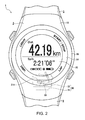
Fig. 2 is a front view showing the front surface side of the wrist device. -
Fig. 3 is a sectional view of the wrist device. -
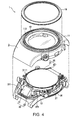
Fig. 4 is an exploded perspective view of the wrist device. -
Fig. 5 is an exploded perspective view showing a display section, a spacer, a circuit board, a circuit case, and an antenna of the wrist device. -
Fig. 6 is an exploded perspective view showing the spacer and the antenna of the wrist device. -
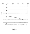
Fig. 7 is a graph showing a relation between a first gap dimension H1 between an antenna main body and a bezel and a return loss. -
Fig. 8 is a graph showing a relation between the first gap dimension H1 and a frequency band. -
Fig. 9 is a graph showing a relation between the first gap dimension H1 and upper hemisphere efficiency. -
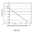
Fig. 10 is a graph showing a relation between the first gap dimension H1 and an axial ratio of a circularly polarized wave. - A
wrist device 1, which is an embodiment of an antenna built-in portable device according to the invention is explained below with reference to the drawings. - As shown in
Fig. 1 , thewrist device 1 in this embodiment is a watch-type device worn on the wrist of a user. Thewrist device 1 incorporates a GPS function for receiving, with a GPS receiver, satellite signals (GPS signals) transmitted fromseveral GPS satellites 100 in the sky and learning the present position. - Consequently, the
wrist device 1 can automatically measure, for example, a distance, speed, and a route of running according to position information and times of the GPS signals and can support exercise of the user. - As shown in
Figs. 2 to 4 as well, thewrist device 1 includes anarmor case 2 and aband 3. In thewrist device 1, a side for visually recognizing time and measurement data is represented as front surface side and a side worn on the arm is represented as rear surface side. When displayed information is seen on the front surface of thewrist device 1, an upper side is represented as 12 o'clock side and a lower side is represented as 6 o'clock side. The upper side and the lower side are set according to time display in a general analog watch. A direction connecting the rear surface side and the front surface side of the wrist device 1 (a direction of an arrow A1 shown inFig. 3 ) is represented as thickness direction A1 of thewrist device 1. - The
armor case 2 includes a casemain body 11 and aback cover 12. The casemain body 11 is made of plastics such as polycarbonate resin and is formed in a substantially cylindrical shape. In the casemain body 11, theback cover 12 is attached to the rear surface side, which is the arm side on which thewrist device 1 is worn, and closes an opening on the rear surface side. Theback cover 12 may be made of plastics like the casemain body 11 or may be made of metal such as stainless steel. - As the armor case, an armor case of a one-piece type may be used in which the case
main body 11 and theback cover 12 are integrally formed. - Glass (a windshield) 13, which is a light-transmitting member according to the invention, is attached to an opening on the front surface side of the case
main body 11, that is, thearmor case 2. In order to support theglass 13, as shown inFig. 3 , aprotrusion section 111 projecting to the opening inner side is formed on the inner circumferential surface of the opening on the front surface side of the casemain body 11. Further, on the front surface of the casemain body 11, acircumferential ridge section 112 having an inner circumferential surface, which continues to the inner circumferential surface of the opening, and projecting toward the front surface side of thewrist device 1 is formed. - A
support ring 14 for theglass 13 is locked to the front surface side of theprotrusion section 111. - The
glass 13 is placed on the front surface side of thesupport ring 14. A ring-like gasket 15 is arranged between theglass 13 and theridge section 112. - Therefore, after the
support ring 14 is arranged in theprotrusion section 111 of the casemain body 11, theglass 13 is press-fit in theridge section 112 via thegasket 15, whereby theglass 13 is attached to the casemain body 11. The light-transmitting member is not limited to the member made of the glass and may be a member made of plastics. The light-transmitting member only has to be a tabular member through which the user can visually recognize the rear surface side (adisplay section 20 explained below) from the front surface side thereof. - A
bezel 16 is attached to the front surface side of the casemain body 11. Thebezel 16 is made of metal such as stainless steel or titanium and is formed in a ring shape. Agroove section 161 to be press-fit in the outer circumferential surface of theridge section 112 is formed on the rear surface of thebezel 16. The diameter of the inner circumferential surface of thegroove section 161 is set to a dimension substantially the same as the diameter of the outer circumferential surface of theridge section 112. Therefore, even when theridge section 112 is about to be deformed to the outer circumference side because theglass 13 is press-fit in theridge section 112, it is possible to prevent the deformation of theridge section 112 by press-fitting to attach themetal bezel 16 to theridge section 112 in advance. That is, thebezel 16 also has a function of reinforcing press-fitting and fixing of theglass 13 to the casemain body 11. - It is possible to prevent, with the
bezel 16, theridge section 112 from being deformed to the outer circumference side. Therefore, thegasket 15 is arranged between theglass 13 and theridge section 112 without a gap. As a result, it is possible to secure a necessary waterproof property. - In the internal space between the case
main body 11 and the back cover 12 (the internal space of the armor case 2), as shown inFigs. 4 and5 , thedisplay section 20, aspacer 25, acircuit board 26, and acircuit case 27 are arranged in order from theglass 13 side (the front surface side) to theback cover 12 side (the rear surface side). In the internal space of thearmor case 2, anantenna 30 is arranged laterally to thedisplay section 20, thecircuit board 26, and thecircuit case 27. As shown inFig. 2 , theantenna 30 is arranged on oneband 3 side (the 6 o'clock side in the watch) with respect to thedisplay section 20 located in the surface center of thewrist device 1. - The
display section 20 includes aliquid crystal panel 21 with a backlight and apanel frame 22 that holds theliquid crystal panel 21. Theliquid crystal panel 21 is connected to thecircuit board 26 via aflexible board 23. Thepanel frame 22 is made of a nonconductive member such as plastics. - The
spacer 25 is made of a nonconductive member such as plastics and arranged between thepanel frame 22 and thecircuit board 26. A plurality ofhooks 251 are formed to project on the surface (the surface on theglass 13 side) of thespacer 25. Thepanel frame 22 of thedisplay section 20 is held by thehooks 251. - The
circuit board 26 is mounted with various ICs and the like for controlling the display of thedisplay section 20 and processing a satellite signal received by theantenna 30. - The
circuit case 27 is made of a nonconductive member such as plastics and holds asecondary battery 28, avibration motor 29, and the like. A plurality ofhooks 271 is formed to project on the upper surface of thecircuit case 27. In a state in which thecircuit board 26 is held between thespacer 25 and thecircuit case 27, thehooks 271 are engaged with thespacer 25 to integrate thespacer 25, thecircuit board 26, and thecircuit case 27. - As shown in
Figs. 5 and6 , on opposed surfaces of thespacer 25 and thecircuit case 27, inclinedsurfaces wrist device 1 are formed. In this embodiment, the angle of theinclined surfaces spacer 25 and thecircuit case 27 are integrated, anantenna board 32 of theantenna 30 is held between theinclined surfaces antenna 30. - In particular, on both side surfaces of the
antenna board 32, aprotrusion 321 projecting sideways is formed. Awall section 253, with which the end face on the inclining direction lower side of theprotrusion 321 comes into contact, is formed in thespacer 25. Therefore, the position of theantenna 30 in the direction along theinclined surfaces antenna 30 is held in a predetermined position (a position where a first gap dimension H1 and a second gap dimension H2 explained below are set values) with respect to the casemain body 11 by thespacer 25 and thecircuit case 27. - The
antenna 30 includes an antennamain body 31 configured by an antenna chip for GPS and theantenna board 32 on which the antennamain body 31 is mounted. Therefore, theantenna 30 is configured by an antenna module that includes the antennamain body 31 and theantenna board 32 and receives GPS signals transmitted from theGPS satellites 100. Theantenna board 32 is connected to thecircuit board 26 via acoaxial cable 33. - The antenna
main body 31 is configured by a micro strip antenna (a patch antenna), which is a rectangular parallelepiped planar antenna. In the antennamain body 31, a ground electrode, a dielectric layer, and a radiation electrode not shown in the figure are laminated in this order from theantenna board 32 side toward the casemain body 11. Therefore, theantenna 30 has directivity. As shown inFig. 3 , a maximum radiation direction R1 of theantenna 30 is a direction orthogonal to the plane of theantenna board 32, that is, the surface of the radiation electrode. - As explained above, the
antenna 30 is positioned by thespacer 25 and thecircuit case 27. Therefore, theantenna 30 is arranged in the predetermined position with respect to the casemain body 11. - That is, as shown in
Figs. 2 and3 , in a plan view from theglass 13 side of the wrist device 1 (the front surface side of the wrist device 1), the antennamain body 31 is arranged in a position not overlapping theliquid crystal panel 21 and overlapping thebezel 16. That is, the antennamain body 31 is arranged in a position not overlapping the liquid crystal panel 21 (the outer circumference side of the liquid crystal panel 21) in the thickness direction A1 of thewrist device 1. That is, theantenna 30 is arranged to shift in the 6 o'clock direction of the 12 o'clock direction and the 6 o'clock direction, in which theband 3 is connected, with respect to theliquid crystal panel 21 of thewrist device 1. - At least a part of the antenna
main body 31 overlaps a part of the bezel 16 (a part on the 6 o'clock side of the wrist device 1) in the thickness direction A1. Specifically, in the rectangular parallelepiped antennamain body 31, oneside 3111 among four sides of a surface (a radiation surface 311) on the opposite side of a surface (an attachment surface) opposed to theantenna board 32 is arranged in a position overlapping thebezel 16. That is, the oneside 3111 is a crossing line of aside surface 313, which is opposed to theglass 13 in the antennamain body 31, and theradiation surface 311. - The
radiation surface 311 of the antennamain body 31 is inclined at an angle equal to or larger than 40 degrees and equal to or smaller than 50 degrees, specifically, an angle of 45 degrees with respect to the thickness direction A1. Therefore, the maximum radiation direction R1 is also set to the angle of 45 degrees (the angle equal to or larger than 40 degrees and equal to or smaller than 50 degrees) with respect to the thickness direction A1. - The one
side 3111 nearest to theglass 13 side in theradiation surface 311 of the antennamain body 31 overlaps thebezel 16 in the thickness direction A1. Therefore, thebezel 16 and the antennamain body 31 overlap in the plan view from the front surface side of thewrist device 1. - The antenna
main body 31 is arranged in a position not overlapping thebezel 16 in the maximum radiation direction R1. That is, the first gap dimension H1 shown inFig. 3 between the antennamain body 31 and thebezel 16 is set to be equal to or larger than a first dimension. The first gap dimension H1 is a minimum gap dimension between the antennamain body 31 and thebezel 16 in a direction R2 orthogonal to the maximum radiation direction R1. Specifically, a gap dimension in the direction R2 between the oneside 3111 of the antennamain body 31 and the outer circumferential edge of thebezel 16 is the first gap dimension H1. - The first dimension is set to 1 mm. The first dimension is verified by an experimental example explained below.
- The antenna
main body 31 is arranged, with respect to thebezel 16, in a position where the second gap dimension H2, which is the minimum gap dimension in the thickness direction A1, is equal to or smaller than a second dimension. The second dimension is equal to or larger than the first dimension. In this embodiment, the second dimension is set to 3.0 mm. That is, the second gap dimension H2 is set, for example, in a range of a dimension equal to or larger than 1.3 mm and equal to or smaller than 3. 0 mm and is set to, for example, 2.5 mm. - In this embodiment, since the one
side 3111 of the antennamain body 31 is nearest to thebezel 16, the second gap dimension H2 is a gap dimension in the thickness direction A1 between the oneside 3111 and the rear surface (the surface on theback cover 12 side) of thebezel 16. - Further, an interval in the direction R2 between the antenna
main body 31 and theliquid crystal panel 21 is set to be equal to or larger than the first gap dimension H1. That is, when an extended line passing at the outer circumferential edge of thebezel 16 and extended in a direction along the maximum radiation direction R1 is set, thebezel 16 is configured not to project further to the antennamain body 31 side than the extended line. Therefore, like themetal bezel 16, a metal portion of an ITO (Indium Tin Oxide) electrode or the like of theliquid crystal panel 21 is apart from the antennamain body 31 by the first gap dimension H1 or more in the direction R2 orthogonal to the maximum radiation direction R1. - As shown in
Fig. 1 , thewrist device 1 having the configuration explained above is worn on the arm of the user and used like a wristwatch. When thewrist device 1 is worn on the arm of the user and used, theantenna 30 is arranged on the 6 o'clock side of thewrist device 1. The maximum radiation direction R1 is set in a direction inclining with respect to the thickness direction A1 (crossing the thickness direction A1) and a direction toward the outer side of thebezel 16. - Therefore, during running or walking, the maximum radiation direction R1 of the
antenna 30 often faces the sky direction. Therefore, theantenna 30 can directly receive a satellite signal transmitted from theGPS satellite 100 located in the maximum radiation direction R1 and improve reception sensitivity. - The first gap dimension H1 between the antenna
main body 31 and thebezel 16 in the direction R2 orthogonal to the maximum radiation direction R1 is set to be equal to or larger than the first dimension (1 mm). The antennamain body 31 and thebezel 16 are arranged in positions not overlapping each other in the maximum radiation direction R1. Therefore, a satellite signal transmitted from the maximum radiation direction R1 and received by the antennamain body 31 is not blocked by themetal bezel 16. It is possible to improve the reception sensitivity in the antennamain body 31. - In particular, by setting the first gap dimension H1 to be equal to or larger than 1 mm, it is possible to secure the reception performance of the
antenna 30 as shown inFigs. 7 to 10 . The abscissa inFigs. 7 to 10 indicates the first gap dimension H1 between theantenna 30 and themetal bezel 16. Therefore, a minus value of the first gap dimension H1 indicates that a part of the antennamain body 31 and a part of thebezel 16 overlap each other in the maximum radiation direction R1. -
Fig. 7 shows a return loss that indicates a loss of theantenna 30. A lower value indicates better performance.Fig. 8 shows a frequency band in which the return loss is equal to or smaller than -10 dB. Whereas the frequency of a radio wave used in a GPS signal is 1.57 GHz, there is no practical problem if the frequency band is equal to or higher than 5 MHz.Fig. 9 shows upper hemisphere efficiency and shows an average of sensitivity of a hemisphere section in a satellite direction when thewrist device 1 is worn on the arm.Fig. 10 shows an axial ratio of a circularly polarized wave. - As shown in
Figs. 7 to 10 , concerning all characteristics, it has been confirmed that sensitivity deterioration is low and sufficient performance can be secured if the first gap dimension H1 between themetal bezel 16 and the antenna 30 (the antenna main body 31) is equal to or larger than 1 mm. - Further, the antenna
main body 31 is arranged the first gap dimension H1 or more apart from not only thebezel 16 but also theliquid crystal panel 21. Therefore, it is possible to prevent the metal ITO electrode or the like of theliquid crystal panel 21 from affecting the reception sensitivity in theantenna 30. - Therefore, it is possible to secure reception sensitivity necessary for the
wrist device 1 that receives GPS signals and acquire position information. - Parts of the antenna
main body 31 and thebezel 16 overlap in the thickness direction A1. Therefore, it is possible to block, with themetal bezel 16, a radio wave made incident on thewrist device 1 from the thickness direction A1 and prevent reception in the antennamain body 31. That is, when the user is performing running or the like, satellite signals transmitted from theGPS satellites 100 in the sky are transmitted from the maximum radial direction R1. Therefore, the satellite signals can be directly received by the antennamain body 31. - On the other hand, a part of the satellite signals transmitted from the
GPS satellites 100 are sometimes reflected on a building or the like and made incident on thewrist device 1 at an angle near the horizontal. When both of the satellite signals reflected on the building or the like and the satellite signals directly transmitted from theGPS satellites 100 are received by theantenna 30 and a multipath occurs, a shift of time of the received satellite signals occur. Therefore, it is likely that correct time information and position information cannot be acquired. - On the other hand, in this embodiment, since the
bezel 16 is made of metal and parts of thebezel 16 and the antennamain body 31 overlap each other in the thickness direction A1, reflected waves of the satellite signals can be blocked by thebezel 16. Therefore, it is possible to suppress occurrence of the multipath and improve accuracy of position information that can be acquired by the reception of the satellite signals. - On the front surface of the
wrist device 1, themetal bezel 16 is arranged around theglass 13. Therefore, on the front (the front surface) of thewrist device 1, which is considered to be the face of thewrist device 1, a luxurious metallic ring can be arranged around an information display region formed by thedisplay section 20. It is possible to improve design properties of thewrist device 1. - Moreover, the
bezel 16 can reinforce the holding of theglass 13 by theridge section 112 when theglass 13 is press-fit and can improve waterproof performance by thegasket 15. - Further, since the holding of the
glass 13 can be reinforced by thebezel 16, it is unnecessary to form theridge section 112 thick. Therefore, it is possible to improve design properties, reduce the casemain body 11 in size, and reduce manufacturing costs. - The
antenna 30 is held by thespacer 25 and thecircuit case 27. In particular, theantenna 30 can be positioned by bringing theprotrusion 321 of theantenna board 32 into contact with thewall section 253 formed in thespacer 25. Therefore, it is possible to accurately arrange theantenna 30 with respect to the casemain body 11 in a position where the first gap dimension H1 and the second gap dimension H2 can be secured. - Further, the holding and the position setting of the
antenna 30 are mainly performed by thespacer 25. Therefore, by preparing thespacer 25 corresponding to the size of thearmor case 2, it is possible to position theantenna 30 in the predetermined position even with respect to thearmor case 2 having a different size and hold theantenna 30. Consequently, it is possible to standardize the components other than the casemain body 11, theback cover 12, and thespacer 25 and reduce costs. - The second gap dimension H2 in the thickness direction A1 between the antenna
main body 31 of theantenna 30 and thebezel 16 is suppressed to be equal to or smaller than 3.0 mm. Therefore, it is possible to prevent the thickness dimension of thewrist device 1 from increasing. - Further, by suppressing the second gap dimension H2 to be equal to or smaller than 3.0 mm, it is possible to prevent deterioration in a radio wave blocking effect by the
metal bezel 16. That is, when the second gap dimension H2 increases and the gap between thebezel 16 and the antennamain body 31 increases, it is more highly likely that a radio wave passing the side of thebezel 16 reaches the antennamain body 31 via the gap portion. Therefore, the multipath is likely to occur. On the other hand, by setting the antennamain body 31 near themetal bezel 16, it is possible to secure a reflected wave blocking effect by thebezel 16. A lower limit value of the second gap dimension H2 is specified by the first gap dimension H1. Therefore, the first gap dimension H1 only has to be set to a value that can secure the first dimension or more (e.g., 1 mm or more). - The maximum radiation direction R1 of the
antenna 30 is inclined in the direction in the range of the angle equal to or larger than 40 degrees and equal to or smaller than 50 degrees, specifically, the direction of 45 degrees with respect to the thickness direction A1. Therefore, in thearmor case 2, it is possible to appropriately set a balance between a dimension in the thickness direction A1 of a space necessary for housing theantenna 30 and a dimension in the plane direction orthogonal to the thickness direction A1. It is possible to set the plane size and the thickness dimension of thearmor case 2 to appropriate sizes. - For example, when the inclination angle of the
antenna 30 with respect to the thickness direction A1 is reduced and the maximum radiation direction R1 is brought close to the direction orthogonal to the thickness direction A1, the dimension in the thickness direction A1 of thearmor case 2 in which theantenna 30 is arranged increases. It is difficult to reduce thearmor case 2 in thickness. On the other hand, when the inclination angle of theantenna 30 with respect to the thickness direction A1 is increased and the maximum radiation direction R1 is brought close to the direction along the thickness direction A1, the plane dimension of thearmor case 2 in which theantenna 30 is arranged increases. The maximum radiation direction R1 is close to the horizontal direction when the user wears thewrist device 1 on the arm and performs running or the like. Therefore, the reception sensitivity of satellite signals is deteriorated. - On the other hand, as in this embodiment, if the
antenna 30 is set in the range of 40 to 50 degrees with respect to the thickness direction A1, it is possible to keep thearmor case 2 within an appropriate size and secure the reception sensitivity of satellite signals. - The invention is not limited to the embodiment. Various modifications are possible within the scope of the gist of the invention.
- The light-transmitting member (the glass 13), the
display section 20, and thebezel 16 of thewrist device 1 are not limited to the circular shape and may have other shapes such as an elliptical shape and a rectangular shape. Thearmor case 2 only has to be designed according to the shapes. - The
antenna 30 is not limited to the configuration in the embodiment. For example, the antennamain body 31 is not limited to the configuration in which the ground electrode, the dielectric layer, and the radiation electrode are directly stuck together and laminated. The antennamain body 31 may have a configuration in which other substrates or the like are inserted among these layers. - The arrangement position of the
antenna 30 in thewrist device 1 is not limited to the 6 o'clock side of thedisplay section 20 and may be the 12 o'clock side in thearmor case 2. In this case, thearmor case 2 of thewrist device 1 can be arranged on the inner side of the wrist. - A fixing structure for the
antenna 30 is not limited to the structure in which theantenna 30 is held by thespacer 25 and thecircuit case 27 in the embodiment. Other fixing structures may be used in which, for example, theantenna board 32 is screwed by thecircuit case 27 and thespacer 25. However, the configuration in the embodiment has an advantage that it is possible to improve assembleability. - The first gap dimension H1 is not limited to the dimension equal to or larger than 1 mm. The first gap dimension H1 only has to be at least equal to or larger than 0 mm and may be any dimension as long as the antenna
main body 31 does not overlap thebezel 16 in the maximum radiation direction R1. However, as shown inFigs. 7 to 10 , if the first gap dimension H1 is set to be equal to or larger than 1 mm, there is an advantage that it is possible to improve the reception performance. - The wrist device is not limited to the embodiment and may be an electronic watch and the like including the
antenna 30. The antenna built-in portable device is not limited to the wrist device worn on the arm and can also be applied to a pocket watch, a portable electronic device, and the like. - The display panel of the
display section 20 is not limited to theliquid crystal panel 21 and only has to be small and thin displays that can be built in thewrist device 1 such as an organic EL panel (organic electroluminescence panel) and an EPD (Electrophoretic Display).
Claims (7)
- An antenna built-in portable device comprising:an armor case including an opening at least on a front surface side;a light-transmitting member that closes the opening;a metal bezel attached to the front surface of the armor case and arranged around the light-transmitting member; andan antenna arranged in a space on an inner side of the armor case, whereinthe antenna is a planar antenna, a maximum radiation direction of which is arranged to be directed in a direction away from the bezel crossing a thickness direction of the armor case,the antenna is arranged in a position not overlapping the bezel in the maximum radiation direction of the antenna, andat least a part of the antenna overlaps at least a part of the bezel in a plan view of the bezel.
- The antenna built-in portable device according to claim 1, wherein the antenna is arranged in a position where a first gap space (H1), which is a minimum gap dimension between the bezel and the antenna in a direction orthogonal to the maximum radiation direction, is equal to or larger than a first dimension set in advance.
- The antenna built-in portable device according to claim 1 or 2, wherein the antenna is arranged in a position where a second gap space (H2), which is a minimum gap dimension between the bezel and the antenna in the thickness direction of the armor case, is equal to or smaller than a second dimension set in advance.
- The antenna built-in portable device according to claim 1, 2 or 3, wherein
the antenna is configured by an antenna board and an antenna main body attached to the antenna board,
the antenna main body is formed in a rectangular parallelepiped shape and includes an attachment surface attached to the antenna board, a radiation surface parallel to the attachment surface, and four side surfaces arranged between four sides of the attachment surface and four sides of the radiation surface, and
one side among the four sides of the radiation surface is arranged in a position overlapping the bezel in the thickness direction of the armor case. - The antenna built-in portable device according to any one of the preceding claims, wherein the maximum radiation direction of the antenna is an angle equal to or larger than 40 degrees and equal to or smaller than 50 degrees with respect to the thickness direction of the armor case.
- The antenna built-in portable device according to any one of the preceding claims, wherein
a display panel that displays information is arranged on a rear surface side of the light-transmitting member, and
when an extended line extended along the maximum radiation direction from an outer circumferential edge of the bezel is defined, a portion opposed to the antenna at an outer circumferential edge of the display panel does not project further to the antenna side than the extended line. - The antenna built-in portable device according to any one of the preceding claims, wherein the antenna built-in portable device is a wristwatch type device including a band fixed to the armor case.
Applications Claiming Priority (1)
| Application Number | Priority Date | Filing Date | Title |
|---|---|---|---|
| JP2013219442A JP6277665B2 (en) | 2013-10-22 | 2013-10-22 | Portable device |
Publications (1)
| Publication Number | Publication Date |
|---|---|
| EP2879007A1 true EP2879007A1 (en) | 2015-06-03 |
Family
ID=51743349
Family Applications (1)
| Application Number | Title | Priority Date | Filing Date |
|---|---|---|---|
| EP14189494.9A Withdrawn EP2879007A1 (en) | 2013-10-22 | 2014-10-20 | Portable device with built-in antenna |
Country Status (4)
| Country | Link |
|---|---|
| US (1) | US9912044B2 (en) |
| EP (1) | EP2879007A1 (en) |
| JP (1) | JP6277665B2 (en) |
| CN (1) | CN104570718A (en) |
Families Citing this family (26)
| Publication number | Priority date | Publication date | Assignee | Title |
|---|---|---|---|---|
| US10594025B2 (en) * | 2013-03-11 | 2020-03-17 | Suunto Oy | Coupled antenna structure and methods |
| US11059550B2 (en) | 2013-03-11 | 2021-07-13 | Suunto Oy | Diving computer with coupled antenna and water contact assembly |
| US10734731B2 (en) | 2013-03-11 | 2020-08-04 | Suunto Oy | Antenna assembly for customizable devices |
| US9450297B2 (en) * | 2013-03-11 | 2016-09-20 | Suunto Oy | Antenna for device having conducting casing |
| US11050142B2 (en) | 2013-03-11 | 2021-06-29 | Suunto Oy | Coupled antenna structure |
| US9601824B2 (en) | 2014-07-01 | 2017-03-21 | Microsoft Technology Licensing, Llc | Slot antenna integrated into a resonant cavity of an electronic device case |
| JP2016225736A (en) * | 2015-05-28 | 2016-12-28 | Tdk株式会社 | Electronic equipment |
| US9985341B2 (en) | 2015-08-31 | 2018-05-29 | Microsoft Technology Licensing, Llc | Device antenna for multiband communication |
| JP6812715B2 (en) * | 2016-09-26 | 2021-01-13 | カシオ計算機株式会社 | Sensing electronic device |
| JP6740893B2 (en) | 2016-12-26 | 2020-08-19 | カシオ計算機株式会社 | Electronics |
| JP6841049B2 (en) * | 2017-01-19 | 2021-03-10 | セイコーエプソン株式会社 | How to adjust the frequency of the antenna structure, portable electronic device, and antenna structure |
| CN206546881U (en) * | 2017-03-17 | 2017-10-10 | 深圳市大疆创新科技有限公司 | Wearable remote control equipment and the aircraft with the Wearable remote control equipment |
| EP3693812B1 (en) * | 2017-10-04 | 2022-12-14 | Citizen Watch Co., Ltd. | Radio clock |
| JP2019086414A (en) * | 2017-11-07 | 2019-06-06 | カシオ計算機株式会社 | Electronic timepiece |
| CN107967026B (en) * | 2017-11-23 | 2019-10-25 | Oppo广东移动通信有限公司 | Antenna assembly, terminal equipment and method for improving antenna radiation performance |
| TWI798344B (en) | 2018-02-08 | 2023-04-11 | 芬蘭商順妥公司 | Slot mode antennas |
| TWI790344B (en) | 2018-02-08 | 2023-01-21 | 芬蘭商順妥公司 | Slot mode antennas |
| JP7039313B2 (en) | 2018-02-14 | 2022-03-22 | オムロン株式会社 | Wireless communication devices, sensor devices and wearable devices |
| JP2019140624A (en) | 2018-02-14 | 2019-08-22 | オムロン株式会社 | Radio communication device, sensor device, and wearable device |
| JP7147355B2 (en) * | 2018-08-13 | 2022-10-05 | セイコーエプソン株式会社 | Electronics |
| KR102537495B1 (en) | 2018-10-02 | 2023-05-26 | 삼성전자주식회사 | An electronic device including an antenna module |
| US10539700B1 (en) | 2019-03-14 | 2020-01-21 | Suunto Oy | Diving computer with coupled antenna and water contact assembly |
| CN110034380B (en) * | 2019-04-30 | 2021-06-15 | Oppo广东移动通信有限公司 | Electronic equipment |
| CN217768748U (en) * | 2022-04-19 | 2022-11-08 | 华为技术有限公司 | Electronic equipment and electronic equipment assembly |
| JP2024127210A (en) * | 2023-03-09 | 2024-09-20 | カシオ計算機株式会社 | Clock module and electronic clock |
| US20240388003A1 (en) * | 2023-05-17 | 2024-11-21 | Microsoft Technology Licensing, Llc | Antenna array embedded in thinned region of display panel |
Citations (8)
| Publication number | Priority date | Publication date | Assignee | Title |
|---|---|---|---|---|
| JP2003152582A (en) * | 2001-11-13 | 2003-05-23 | Seiko Epson Corp | Wrist-mounted electronic device with wireless function |
| EP1489471A1 (en) * | 2003-06-18 | 2004-12-22 | Asulab S.A. | Ground connection of a printed circuit board placed in a wristwatch-type electronic device |
| US20050047282A1 (en) * | 2003-09-01 | 2005-03-03 | Casio Computer Co., Ltd. | Wrist watch case, wrist watch with auto time adjusting function by electric wave, and wrist mountable electric device case |
| JP2007266823A (en) * | 2006-03-28 | 2007-10-11 | Casio Comput Co Ltd | Antenna device and manufacturing method thereof |
| US20090059730A1 (en) * | 2007-08-28 | 2009-03-05 | Garmin Ltd. | Watch device having touch-bezel user interface |
| DE202009000651U1 (en) * | 2009-01-20 | 2009-06-10 | Chang, Tseng Yein, Chu-Pei City | Wrist watch with satellite signal receiver |
| EP2284948A1 (en) * | 2009-07-15 | 2011-02-16 | Lg Electronics Inc. | Watch type mobile terminal |
| JP2013061308A (en) | 2011-09-15 | 2013-04-04 | Seiko Epson Corp | Wrist device |
Family Cites Families (13)
| Publication number | Priority date | Publication date | Assignee | Title |
|---|---|---|---|---|
| SG101434A1 (en) * | 1999-12-29 | 2004-01-30 | Asulab Sa | Wristwatch provided with an antenna |
| JP2002290143A (en) * | 2001-03-26 | 2002-10-04 | Tdk Corp | Surface-mounted antenna, substrate on which the same is mounted and mounting method of the surface-mounted antenna |
| US6950685B2 (en) * | 2001-07-05 | 2005-09-27 | Eta Sa Manufacture Horlogère Suisse | Electronic instrument intended to be worn on the wrist and including, in particular, an antenna for receiving and/or transmitting radio-frequency signals |
| JP2005062161A (en) * | 2003-07-25 | 2005-03-10 | Seiko Epson Corp | Electronic clock with built-in antenna |
| JP4015104B2 (en) * | 2003-11-27 | 2007-11-28 | カシオ計算機株式会社 | Antenna device and clock |
| JP4747628B2 (en) | 2005-03-28 | 2011-08-17 | 日産自動車株式会社 | Automotive antenna |
| CN101490630B (en) * | 2006-07-13 | 2011-10-26 | 西铁城控股株式会社 | Clock with wireless function |
| JP4983293B2 (en) | 2007-02-20 | 2012-07-25 | カシオ計算機株式会社 | Radio clock |
| JP2009186373A (en) * | 2008-02-07 | 2009-08-20 | Seiko Epson Corp | Electronic clock with built-in antenna |
| JP5135265B2 (en) | 2009-03-13 | 2013-02-06 | シチズン時計株式会社 | Electronic clock with wireless function |
| JP5776359B2 (en) | 2011-06-17 | 2015-09-09 | カシオ計算機株式会社 | Sensitivity adjusting device and wristwatch |
| US8902716B2 (en) | 2011-06-17 | 2014-12-02 | Casio Computer Co., Ltd. | Sensitivity adjustment device, radio wave communication device and watch |
| JP5811619B2 (en) | 2011-06-17 | 2015-11-11 | カシオ計算機株式会社 | Sensitivity adjusting device and wristwatch |
-
2013
- 2013-10-22 JP JP2013219442A patent/JP6277665B2/en not_active Expired - Fee Related
-
2014
- 2014-10-20 US US14/518,982 patent/US9912044B2/en not_active Expired - Fee Related
- 2014-10-20 EP EP14189494.9A patent/EP2879007A1/en not_active Withdrawn
- 2014-10-21 CN CN201410562111.1A patent/CN104570718A/en active Pending
Patent Citations (8)
| Publication number | Priority date | Publication date | Assignee | Title |
|---|---|---|---|---|
| JP2003152582A (en) * | 2001-11-13 | 2003-05-23 | Seiko Epson Corp | Wrist-mounted electronic device with wireless function |
| EP1489471A1 (en) * | 2003-06-18 | 2004-12-22 | Asulab S.A. | Ground connection of a printed circuit board placed in a wristwatch-type electronic device |
| US20050047282A1 (en) * | 2003-09-01 | 2005-03-03 | Casio Computer Co., Ltd. | Wrist watch case, wrist watch with auto time adjusting function by electric wave, and wrist mountable electric device case |
| JP2007266823A (en) * | 2006-03-28 | 2007-10-11 | Casio Comput Co Ltd | Antenna device and manufacturing method thereof |
| US20090059730A1 (en) * | 2007-08-28 | 2009-03-05 | Garmin Ltd. | Watch device having touch-bezel user interface |
| DE202009000651U1 (en) * | 2009-01-20 | 2009-06-10 | Chang, Tseng Yein, Chu-Pei City | Wrist watch with satellite signal receiver |
| EP2284948A1 (en) * | 2009-07-15 | 2011-02-16 | Lg Electronics Inc. | Watch type mobile terminal |
| JP2013061308A (en) | 2011-09-15 | 2013-04-04 | Seiko Epson Corp | Wrist device |
Also Published As
| Publication number | Publication date |
|---|---|
| CN104570718A (en) | 2015-04-29 |
| JP2015081825A (en) | 2015-04-27 |
| US9912044B2 (en) | 2018-03-06 |
| JP6277665B2 (en) | 2018-02-14 |
| US20150109172A1 (en) | 2015-04-23 |
Similar Documents
| Publication | Publication Date | Title |
|---|---|---|
| US9912044B2 (en) | Antenna built-in portable device | |
| EP3410233B1 (en) | Timepiece with wireless communication function | |
| US9869975B2 (en) | Electronic timepiece | |
| EP2954591B1 (en) | Wrist-worn electronic device with bezel antenna configuration | |
| CN102467085B (en) | Electronic device equipped with antenna device and solar panel | |
| US11221591B2 (en) | Electronic timepiece having a conductive member spaced apart from a planar antenna | |
| JP5564953B2 (en) | ANTENNA DEVICE AND ELECTRONIC DEVICE | |
| US9886003B2 (en) | Electronic timepiece | |
| US10761491B2 (en) | Portable electronic device | |
| CN109752946B (en) | digital watch | |
| JP7409403B2 (en) | electronic clock | |
| JP6841049B2 (en) | How to adjust the frequency of the antenna structure, portable electronic device, and antenna structure | |
| US10739732B2 (en) | Antenna device and timepiece | |
| US9568892B2 (en) | Electronic timepiece | |
| JP7405185B2 (en) | Antenna equipment and clocks | |
| JP5796670B2 (en) | Arm-mounted electronic device | |
| US20200229722A1 (en) | Portable electronic apparatus and wrist apparatus | |
| JP2008205531A (en) | ANTENNA DEVICE AND ELECTRONIC DEVICE | |
| JP2000147169A (en) | Wrist watch with antenna | |
| EP4597235A1 (en) | Electronic device and electronic timepiece | |
| CN117762004A (en) | Electronic device and electronic timepiece |
Legal Events
| Date | Code | Title | Description |
|---|---|---|---|
| PUAI | Public reference made under article 153(3) epc to a published international application that has entered the european phase |
Free format text: ORIGINAL CODE: 0009012 |
|
| 17P | Request for examination filed |
Effective date: 20141020 |
|
| AK | Designated contracting states |
Kind code of ref document: A1 Designated state(s): AL AT BE BG CH CY CZ DE DK EE ES FI FR GB GR HR HU IE IS IT LI LT LU LV MC MK MT NL NO PL PT RO RS SE SI SK SM TR |
|
| AX | Request for extension of the european patent |
Extension state: BA ME |
|
| R17P | Request for examination filed (corrected) |
Effective date: 20151127 |
|
| RBV | Designated contracting states (corrected) |
Designated state(s): AL AT BE BG CH CY CZ DE DK EE ES FI FR GB GR HR HU IE IS IT LI LT LU LV MC MK MT NL NO PL PT RO RS SE SI SK SM TR |
|
| STAA | Information on the status of an ep patent application or granted ep patent |
Free format text: STATUS: THE APPLICATION HAS BEEN WITHDRAWN |
|
| 18W | Application withdrawn |
Effective date: 20190304 |