EP2878934B1 - Wet gas flow measuring method and apparatus - Google Patents
Wet gas flow measuring method and apparatus Download PDFInfo
- Publication number
- EP2878934B1 EP2878934B1 EP13823679.9A EP13823679A EP2878934B1 EP 2878934 B1 EP2878934 B1 EP 2878934B1 EP 13823679 A EP13823679 A EP 13823679A EP 2878934 B1 EP2878934 B1 EP 2878934B1
- Authority
- EP
- European Patent Office
- Prior art keywords
- gas
- opt
- gvf
- flow
- denotes
- Prior art date
- Legal status (The legal status is an assumption and is not a legal conclusion. Google has not performed a legal analysis and makes no representation as to the accuracy of the status listed.)
- Active
Links
- 238000000034 method Methods 0.000 title claims description 50
- 239000011800 void material Substances 0.000 claims description 123
- 239000007788 liquid Substances 0.000 claims description 64
- 230000007774 longterm Effects 0.000 claims description 13
- 230000009897 systematic effect Effects 0.000 claims description 4
- 239000007789 gas Substances 0.000 description 263
- 239000012071 phase Substances 0.000 description 81
- 238000010586 diagram Methods 0.000 description 16
- 238000004519 manufacturing process Methods 0.000 description 13
- 238000012937 correction Methods 0.000 description 12
- 239000000203 mixture Substances 0.000 description 10
- 239000007791 liquid phase Substances 0.000 description 8
- 238000007726 management method Methods 0.000 description 8
- 239000003595 mist Substances 0.000 description 8
- 238000000926 separation method Methods 0.000 description 7
- 238000005259 measurement Methods 0.000 description 6
- 238000005457 optimization Methods 0.000 description 5
- 238000004364 calculation method Methods 0.000 description 4
- 239000012530 fluid Substances 0.000 description 4
- XLYOFNOQVPJJNP-UHFFFAOYSA-N water Chemical compound O XLYOFNOQVPJJNP-UHFFFAOYSA-N 0.000 description 4
- 229930195733 hydrocarbon Natural products 0.000 description 3
- 150000002430 hydrocarbons Chemical class 0.000 description 3
- 239000004215 Carbon black (E152) Substances 0.000 description 2
- VNWKTOKETHGBQD-UHFFFAOYSA-N methane Chemical compound C VNWKTOKETHGBQD-UHFFFAOYSA-N 0.000 description 2
- 238000012986 modification Methods 0.000 description 2
- 230000004048 modification Effects 0.000 description 2
- 230000007547 defect Effects 0.000 description 1
- 230000000694 effects Effects 0.000 description 1
- 238000012423 maintenance Methods 0.000 description 1
- 239000003345 natural gas Substances 0.000 description 1
- 238000000746 purification Methods 0.000 description 1
- 238000005070 sampling Methods 0.000 description 1
Images

Classifications
-
- G—PHYSICS
- G01—MEASURING; TESTING
- G01F—MEASURING VOLUME, VOLUME FLOW, MASS FLOW OR LIQUID LEVEL; METERING BY VOLUME
- G01F3/00—Measuring the volume flow of fluids or fluent solid material wherein the fluid passes through the meter in successive and more or less isolated quantities, the meter being driven by the flow
- G01F3/30—Wet gas-meters
-
- G—PHYSICS
- G01—MEASURING; TESTING
- G01F—MEASURING VOLUME, VOLUME FLOW, MASS FLOW OR LIQUID LEVEL; METERING BY VOLUME
- G01F1/00—Measuring the volume flow or mass flow of fluid or fluent solid material wherein the fluid passes through a meter in a continuous flow
- G01F1/05—Measuring the volume flow or mass flow of fluid or fluent solid material wherein the fluid passes through a meter in a continuous flow by using mechanical effects
- G01F1/34—Measuring the volume flow or mass flow of fluid or fluent solid material wherein the fluid passes through a meter in a continuous flow by using mechanical effects by measuring pressure or differential pressure
- G01F1/36—Measuring the volume flow or mass flow of fluid or fluent solid material wherein the fluid passes through a meter in a continuous flow by using mechanical effects by measuring pressure or differential pressure the pressure or differential pressure being created by the use of flow constriction
- G01F1/363—Measuring the volume flow or mass flow of fluid or fluent solid material wherein the fluid passes through a meter in a continuous flow by using mechanical effects by measuring pressure or differential pressure the pressure or differential pressure being created by the use of flow constriction with electrical or electro-mechanical indication
-
- G—PHYSICS
- G01—MEASURING; TESTING
- G01F—MEASURING VOLUME, VOLUME FLOW, MASS FLOW OR LIQUID LEVEL; METERING BY VOLUME
- G01F1/00—Measuring the volume flow or mass flow of fluid or fluent solid material wherein the fluid passes through a meter in a continuous flow
- G01F1/74—Devices for measuring flow of a fluid or flow of a fluent solid material in suspension in another fluid
-
- G—PHYSICS
- G01—MEASURING; TESTING
- G01F—MEASURING VOLUME, VOLUME FLOW, MASS FLOW OR LIQUID LEVEL; METERING BY VOLUME
- G01F1/00—Measuring the volume flow or mass flow of fluid or fluent solid material wherein the fluid passes through a meter in a continuous flow
- G01F1/76—Devices for measuring mass flow of a fluid or a fluent solid material
- G01F1/86—Indirect mass flowmeters, e.g. measuring volume flow and density, temperature or pressure
- G01F1/88—Indirect mass flowmeters, e.g. measuring volume flow and density, temperature or pressure with differential-pressure measurement to determine the volume flow
Definitions
- the invention relates to a field of measurement, particularly, to a method for measuring wet gas flow and apparatus thereof.
- wet gas refers to natural gas wherein amounts of liquid hydrocarbons, water vapor, and free water are significantly higher than those required by pipeline conveying.
- wet gas can be simply defined as a gas which contains some liquid, wherein the amount of liquid can vary from a small amount of water or hydrocarbon to substantial amount of water and hydrocarbon.
- wet gas is defined as gas/liquid system with a Lockhart-Martinelli parameter smaller than approximately 0.3.
- wet gas metering techniques in the art primarily include two sorts, wherein one sort is a separation metering method, and another sort is the online metering method without any separation.
- the separation metering method is to utilize a separator to separate a wet gas fluid into a gas phase fluid and a liquid phase fluid, and then to respectively meter the flows of the gas phase and the liquid phase at respective outlet thereof.
- the separation effect of the separator on wet gas is poor, and due to the phenomena of liquid carry-over and gas carry-under, the error of the metering result is high.
- the structure and the flow process of the separator are complex, and thus the maintenances and managements to the system are complex with many links which should be controlled. Thus, fee for maintaining the operation of the system is high, and the metering process is disadvantageous to realize automatic managements to production process.
- the online metering method without any separation for wet gas can have two developing trends.
- the first developing trend relates to the use a single-phase gas flow meter (e.g., a Coriolis mass flow meter, a V-cone flow meter, an orifice plate flow meter, a turbine flow meter, a ultrasonic flow meter, a Venturi flow meter, a vortex flow meter, etc.) to meter wet gas, and is committed to study and develop various experiential models to find out "correction coefficients", thereby to correct metered results, so that a so-called gas flow rate value can be obtained.
- metering means for a liquid flow rate generally includes a sampling method or a tracing method.
- the limitations of this method and challenges confronted thereby mainly include the following aspects:
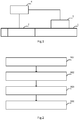
- FIG. 1 depicts an online metering scheme in the prior art, in which a differential pressure type flow measuring device 2 is used to measure the total flow differential pressure value of wet gas in pipeline 1; a phase fraction meter 3 arranged in the pipeline 1 is used to measure the gas void fraction of the wet gas in the pipeline 1; and a flow calculating module 4, based on the total flow differential pressure value and gas void fraction of the wet gas, can be used to calculate the gas volume flow rate Q g and the liquid volume flow rate Q l .
- phase fraction meter Since only one phase fraction meter is arranged in the pipeline 1, and the phase fraction meter per se involve a "drift" (e.g., the counting drift of a gamma-phase fraction meter), metering errors will be produced. Thus, precise metering to the gas void fraction of wet gas in a pipeline cannot be achieved.
- drift e.g., the counting drift of a gamma-phase fraction meter
- US2007/006640A1 relates to an apparatus for the measurement of a wet gas flow.
- the apparatus separates a fluid flow into a gas component and a liquid component by a separation device to flow within a gas leg portion and a liquid leg portion of the pipe.
- the wet gas flow (gas and liquid carry-over from separation) in the gas leg portion is measured in one embodiment by measuring the total flow differential pressure value via a differential pressure type flow measuring device (DP meter 308) and by measuring the gas void fraction by a phase fraction meter (sonar flow meter).
- DP meter 308 differential pressure type flow measuring device
- the gas volume rate and the liquid volume flow rate is then calculated by the two corresponding values in a flow calculating module.
- the technical problem to be solved by the invention is to provide a method for measuring wet gas flow and apparatus thereof, i.e., as the gas void fraction of the wet gas in the pipeline is detected by a redundant phase fraction meter, the gas volume flow rate Q g and the liquid volume flow rate Q l can be measured accurately, which meets the requirements on production measurements of oil and gas field and facilitates management improvement and production optimization of oil-gas reservoir.
- An aspect of the invention is to provide a method for measuring a wet gas flow, comprising the following steps:
- Another aspect of the invention is to provide a wet gas flow measuring apparatus, comprising a pipeline, a differential pressure type flow measuring device, at least two phase fraction meters, and a flow calculating module, wherein the differential pressure type flow measuring device and said at least two phase fraction meters are respectively installed on the pipeline, and wherein:
- a differential pressure type flow measuring device is used to measure the total flow differential pressure value of wet gas in a pipeline; at least two phase fraction meters are respectively used to measure the gas void fractions of wet gas in the pipeline; a flow calculating module, based on the gas void fractions respectively measured by the at least two phase fraction meters, can be used to calculate the optimized gas void fraction GVF opt , and the flow calculating module, based on the total flow differential pressure value ⁇ P and the optimized gas void fraction GVF opt , can be used to calculate the gas volume flow rate Q g and the liquid volume flow rate Q l .
- the gas volume flow rate Q g and the liquid volume flow rate Q l can be measured accurately, which meets the requirements on production measurements of oil and gas field and facilitates management improvement and production optimization of oil-gas reservoir.
- FIG. 2 is a diagram which describes one example for the wet gas flow measuring method of the invention, and as shown in Figure 2 , the wet gas flow measuring method in the embodiment may comprise the following steps:
- a differential pressure type flow measuring device is used to measure the total flow differential pressure value ⁇ P of wet gas in a pipeline; at least two phase fraction meters are respectively used to measure the gas void fractions of wet gas in the pipeline; a flow calculating module, based on the gas void fractions respectively measured by the at least two phase fraction meters, can be used to calculate the optimized gas void fraction GVF opt , and the flow calculating module, based on the total flow differential pressure value ⁇ P and the optimized gas void fraction GVF opt , can be used to calculate the gas volume flow rate Q g and the liquid volume flow rate Q l .
- the gas volume flow rate Q g and the liquid volume flow rate Q l can be measured accurately, which meets the requirements on production measurements of oil and gas field and facilitates management improvement and production optimization of oil-gas reservoir.
- the axial lines of the at least two phase fraction meters are respectively intersected with the axial direction of the pipeline and perpendicular thereto. Since the axial line of each phase fraction meter is respectively intersected with the axial direction of the pipeline and perpendicular thereto, the precision of measuring result can be further assured.
- the method as shown in Figure 3 may be used to calculate the gas volume flow rate Q g and the liquid volume flow rate Q l .
- a person skilled in the art will know that the method as shown in Figure 3 merely is illustrative, and thus a person skilled in the art can use other alternative methods to take the calculation.
- the method according to the invention for calculating the gas volume flow rate Q g and the liquid volume flow rate Q l comprises the following steps:
- the flow calculating module can calculate the optimized gas void fraction GVF opt by acquiring the mean value of the above gas void fractions which are respectively measured by at least two phase fraction meters.
- the calculation may be carried out with a method for calculating an arithmetic mean value, a geometric mean volume, or a root mean square mean value.
- the flow calculating module calculates the optimized gas void fraction GVF opt by a method for calculating a weighted mean value as shown in Figure 4 .
- Figure 4 is a diagram which describes the invention for calculating the optimized gas void fraction by utilizing a weighed means value. As shown in Figure 4 , the method for calculating the optimized gas void fraction comprises the following steps:
- Figure 5 is a diagram which describes another example for a wet gas flow measuring method. As compared with the example as shown in Figure 2 , the example as shown in Figure 5 further comprises the step 501 of the slip correction for the gas volume flow rate Q g and the liquid volume flow rate Q l after they are obtained in the step 204.
- a solution which is usually used in the art for solving the technical problem is to fit relevant experimental data so as to correct the gas flow rate and the liquid flow rate.
- the disadvantage of the correction resides in strong dependences of experiential models on experimental data and measuring conditions, so that the method cannot achieve the balance of the universality and the precision.
- the defect in the prior art may be overcome by utilizing a slip correction method provided, i.e., the precise analytic solution for the slip of gas and liquid annular mist flow, to correct the gas volume flow rate Q g and the liquid volume flow rate Q l , thereby to further increase measuring precisions.
- the step 203 is carried out according to the example as show in Figure 4
- the step 204 may be carried out according to the example as show in Figure 3 .
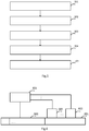
- FIG. 6 is a diagram which describes an example for the wet gas flow measuring apparatus of the invention.
- the wet gas flow measuring apparatus in the embodiment comprises a pipeline 601, a differential pressure type flow measuring device 602, at least two phase fraction meters 603, and a flow calculating module 604, wherein the differential pressure type flow measuring device 602 and said at least two phase fraction meters 603 are respectively installed on the pipeline, and wherein the pipeline 601 is used to convey the wet gas; the differential pressure type flow measuring device 602 is used to measure the total flow differential pressure value of wet gas in the pipeline; at least two phase fraction meters 603 are respectively used to measure the gas void fractions of wet gas in the pipeline; a flow calculating module 604, according to the gas void fractions respectively measured by the at least two phase fraction meters 603, can be used to calculate the optimized gas void fraction GVF opt , and the flow calculating module 604, according to the total flow differential pressure value ⁇ P and the optimized gas void fraction GVF opt , can be used to calculate the gas volume flow rate
- a differential pressure type flow measuring device is used to measure the total flow differential pressure value of wet gas in a pipeline; at least two phase fraction meters are respectively used to measure the gas void fractions of wet gas in the pipeline; a flow calculating module, according to the gas void fractions respectively measured by the at least two phase fraction meters, can be used to calculate the optimized gas void fraction GVF opt , and the flow calculating module, according to the total flow differential pressure value ⁇ P and the optimized gas void fraction GVF opt , can be used to calculate the gas volume flow rate Q g and the liquid volume flow rate Q l .
- the gas volume flow rate Q g and the liquid volume flow rate Q l can be measured accurately, which meets the requirements on production measurements of oil and gas field and facilitates management improvement and production optimization of oil-gas reservoir.
- the axial lines of the at least two phase fraction meters are respectively intersected with the axial direction of the pipeline and perpendicular thereto. Since the axial line of each phase fraction meter is respectively intersected with the axial direction of the pipeline and perpendicular thereto, the precision of measuring result can be further assured.
- said at least two phase fraction meters may either be installed on the same one section, or be installed on different sections of the pipeline.
- the flow calculating module 604 in particular, according to the optimized gas void fraction GVF opt , can calculate the mixed density ⁇ mix of wet gas; it, according to the total flow differential pressure value ⁇ P and the mixed density ⁇ mix of wet gas, can calculate the total volume flow rate Q of wet gas; and it, according to the total volume flow rate Q and the optimized gas void fraction GVF opt , can calculate the gas volume flow rate Q g and the liquid volume flow rate Q l .
- the flow calculating module 604 with a method for acquiring a mean value, can calculate the optimized gas void fraction GVF opt by calculating the mean value of the above gas void fractions which are respectively measured by at least two phase fraction meters. For example, the calculation may be carried out with a method for calculating an arithmetic mean value, a geometric mean value, or a root mean square mean value, etc.
- the flow calculating module 604 utilizes a method for calculating a weighed mean value to calculate the optimized gas void fraction GVF opt .
- the flow calculating module 604 specifically utilizes the comprehensive reliability function NICE () to obtain the optimized gas void fraction GVF opt :
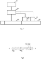
- FIG. 7 is a diagram which describes another example for a wet gas flow measuring apparatus.
- the wet gas flow measuring apparatus further comprises a slip correction module 701 for the correction of the gas volume flow rate Q g and the liquid volume flow rate Q l so as to acquire a corrected gas volume flow rate Q' g and a corrected liquid volume rate Q' l :
- Q 1 ′ Q 1 1 ⁇ GVF opt + Slip * GVF opt
- Q g ′ Q g * Slip 1 ⁇ GVF opt + Slip * GVF opt
- FIG 8 is a diagram which describes an example for horizontal arrangement of the wet gas flow measuring apparatus of the invention.
- the arrow represents the flowing direction of wet gas; sign 801 denotes the pipeline; sign 802 denotes a differential pressure type flow measuring device; sign 803 denotes the phase fraction meter (for the aim of simplifying the figure, merely two phase fraction meters are illustrated).
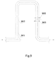
- Figure 9 is a diagram which describes an example for vertical arrangement of the wet gas flow measuring apparatus of the invention.
- the arrow represents the flowing direction of the wet gas;
- the sign 901 denotes the pipeline;
- sign 902 denotes a differential pressure type flow measuring device;
- sign 903 denotes the phase fraction meter (for the aim of simplifying the figure, merely two phase fraction meters are illustrated).
- a pressure transmitter and a temperature transmitter are further installed for measuring pressure and temperature in the pipeline respectively, thereby to facilitate management improvement and production optimization of oil-gas reservoir.
Landscapes
- Physics & Mathematics (AREA)
- Fluid Mechanics (AREA)
- General Physics & Mathematics (AREA)
- Measuring Volume Flow (AREA)
Description
- The invention relates to a field of measurement, particularly, to a method for measuring wet gas flow and apparatus thereof.
- Wet gas refers to natural gas wherein amounts of liquid hydrocarbons, water vapor, and free water are significantly higher than those required by pipeline conveying. Alternatively, wet gas can be simply defined as a gas which contains some liquid, wherein the amount of liquid can vary from a small amount of water or hydrocarbon to substantial amount of water and hydrocarbon. Generally wet gas is defined as gas/liquid system with a Lockhart-Martinelli parameter smaller than approximately 0.3. During the exploring of a gas field, the metering of wet gas is involved in individual processes from exploring single-well to integral-delivery of multi-well, purification treatment, and pressured delivery. Metering data of wet gas can facilitate to know about production ability and production conditions of gas wells, and is the primary basis for optimizing the production and improving managements to gas reservoir.
- Currently, wet gas metering techniques in the art primarily include two sorts, wherein one sort is a separation metering method, and another sort is the online metering method without any separation.
- The separation metering method is to utilize a separator to separate a wet gas fluid into a gas phase fluid and a liquid phase fluid, and then to respectively meter the flows of the gas phase and the liquid phase at respective outlet thereof. However, the separation effect of the separator on wet gas is poor, and due to the phenomena of liquid carry-over and gas carry-under, the error of the metering result is high. Secondly, the structure and the flow process of the separator are complex, and thus the maintenances and managements to the system are complex with many links which should be controlled. Thus, fee for maintaining the operation of the system is high, and the metering process is disadvantageous to realize automatic managements to production process.
- The online metering method without any separation for wet gas can have two developing trends. The first developing trend relates to the use a single-phase gas flow meter (e.g., a Coriolis mass flow meter, a V-cone flow meter, an orifice plate flow meter, a turbine flow meter, a ultrasonic flow meter, a Venturi flow meter, a vortex flow meter, etc.) to meter wet gas, and is committed to study and develop various experiential models to find out "correction coefficients", thereby to correct metered results, so that a so-called gas flow rate value can be obtained. In such wet gas metering method, metering means for a liquid flow rate generally includes a sampling method or a tracing method. However, the limitations of this method and challenges confronted thereby mainly include the following aspects:
- (1) the scope for which the "correction coefficient" of the gas flow rate is applicable is limited and depends on the liquid flow rate, and however, the method for measuring the liquid flow rate decides that its precision is not high even poor; and
- (2) the method utilizing the "correction coefficient" of the gas flow rate is limited to be used for wet gas having a very high gas content and a very low liquid phase content, and with the increase of liquid component content in the wet gas, the error of the method will become unacceptable.
- The second developing trend relates to metering wet gas by following or modifying online metering technique of a multi-phase flow.
Figure 1 depicts an online metering scheme in the prior art, in which a differential pressure typeflow measuring device 2 is used to measure the total flow differential pressure value of wet gas inpipeline 1; aphase fraction meter 3 arranged in thepipeline 1 is used to measure the gas void fraction of the wet gas in thepipeline 1; and aflow calculating module 4, based on the total flow differential pressure value and gas void fraction of the wet gas, can be used to calculate the gas volume flow rate Qg and the liquid volume flow rate Ql. - Since only one phase fraction meter is arranged in the
pipeline 1, and the phase fraction meter per se involve a "drift" (e.g., the counting drift of a gamma-phase fraction meter), metering errors will be produced. Thus, precise metering to the gas void fraction of wet gas in a pipeline cannot be achieved. -
US2007/006640A1 relates to an apparatus for the measurement of a wet gas flow. The apparatus separates a fluid flow into a gas component and a liquid component by a separation device to flow within a gas leg portion and a liquid leg portion of the pipe. The wet gas flow (gas and liquid carry-over from separation) in the gas leg portion is measured in one embodiment by measuring the total flow differential pressure value via a differential pressure type flow measuring device (DP meter 308) and by measuring the gas void fraction by a phase fraction meter (sonar flow meter). The gas volume rate and the liquid volume flow rate is then calculated by the two corresponding values in a flow calculating module. - The technical problem to be solved by the invention is to provide a method for measuring wet gas flow and apparatus thereof, i.e., as the gas void fraction of the wet gas in the pipeline is detected by a redundant phase fraction meter, the gas volume flow rate Qg and the liquid volume flow rate Ql can be measured accurately, which meets the requirements on production measurements of oil and gas field and facilitates management improvement and production optimization of oil-gas reservoir.
- An aspect of the invention is to provide a method for measuring a wet gas flow, comprising the following steps:
- (a) measuring the total flow differential pressure value ΔP of wet gas in a pipeline via a differential pressure type flow measuring device;
- (b) measuring gas void fraction of the wet gas in the pipeline via at least two phase fraction meters, respectively;
- (c) obtaining optimized gas void fraction GVF opt by a flow calculating module based on the gas void fractions respectively measured by the at least two phase fraction meters; and
- (d) calculating the gas volume flow rate Qg and the liquid volume flow rate Ql by the flow calculating module based on the total flow differential pressure value ΔP and the optimized gas void fraction GVFopt of the wet gas;
- (c1) calculating the short-term local reliability function F() of the gas void fraction Xi measured by each phase fraction meter: F(Xi) = D(Xi) = E([X¡ - E(Xi ]2), wherein Xi denotes the time sequence of the gas void fraction measured by the phase fraction meter i, 1≤i≤N; N denotes the number of phase fraction meters; D() denotes a variance function; and E() denotes an expectation function;
- (c2) constructing a long-term whole reliability function LF() for the gas void fraction Xi measured by each phase fraction meter:


- (c3) constructing a comprehensive reliability function NICE() for the gas void fraction Xi measured by each phase fraction meter by utilizing the short-term local reliability function F() and the long-term whole reliability function LF():

- (c4) obtaining the optimized gas void fraction GVFopt by utilizing the comprehensive reliability function NICE():

- Another aspect of the invention is to provide a wet gas flow measuring apparatus, comprising a pipeline, a differential pressure type flow measuring device, at least two phase fraction meters, and a flow calculating module, wherein the differential pressure type flow measuring device and said at least two phase fraction meters are respectively installed on the pipeline, and wherein:
- the pipeline is used to convey the wet gas;
- the differential pressure type flow measuring device is used to measure the total flow differential pressure value ΔP of wet gas in the pipeline;
- the at least two phase fraction meters are respectively used to measure the gas void fractions of wet gas in the pipeline; and
- the flow calculating module is used to calculate the optimized gas void fraction GVFopt based on the gas void fractions respectively measured by the at least two phase fraction meters; and the flow calculating module is used to calculate the gas volume flow rate Qg and the liquid volume flow rate Ql based on the total flow differential pressure value ΔP and the optimized gas void fraction GVFopt;
- the flow calculating module calculates the short-term local reliability function F() of the gas void fraction Xi measured by each phase fraction meter: F(Xi) = D(Xi) = E([X¡ - E(Xi ]2), wherein Xi denotes the time sequence of the gas void fraction measured by the phase fraction meter i, 1≤i≤N; N denotes the number of the phase fraction meters; D() denotes a variance function; and E() denotes an expectation function;
- the flow calculating module constructs a long-term whole reliability function LF() for the gas void fraction Xi measured by each phase fraction meter:


- which 0≤α≤1, 0≤m≤M-1, wherein M denotes the number of the gas void fractions included in the time sequence, and Xi [m] denotes the mth gas void fraction in the time sequence of the gas void fraction measured by the phase fraction meter i;
- the flow calculating module constructs a comprehensive reliability function NICE() of the gas void fraction Xi measured by each phase fraction meter by utilizing the short-term local reliability function F() and the long-term whole reliability function LF(), wherein NICE

- the flow calculating module utilizes the comprehensive reliability function NICE() to obtain the optimized gas void fraction GVFopt:

- In accordance with the invention, a differential pressure type flow measuring device is used to measure the total flow differential pressure value of wet gas in a pipeline; at least two phase fraction meters are respectively used to measure the gas void fractions of wet gas in the pipeline; a flow calculating module, based on the gas void fractions respectively measured by the at least two phase fraction meters, can be used to calculate the optimized gas void fraction GVFopt, and the flow calculating module, based on the total flow differential pressure value ΔP and the optimized gas void fraction GVFopt, can be used to calculate the gas volume flow rate Qg and the liquid volume flow rate Ql. As the gas void fraction of the wet gas in the pipeline is detected by a redundant phase fraction meter, the gas volume flow rate Qg and the liquid volume flow rate Ql can be measured accurately, which meets the requirements on production measurements of oil and gas field and facilitates management improvement and production optimization of oil-gas reservoir.
-
-
Figure 1 is a diagram which describes a scheme for measuring wet gas flow in the prior art. -
Figure 2 is a diagram which describes an example for the wet gas flow measuring method of the invention. -
Figure 3 is a diagram which describes an example for calculating the gas volume flow rate and the liquid volume flow rate of the invention. -
Figure 4 is a diagram which describes an example for calculating the optimized gas void fraction of the invention. -
Figure 5 is a diagram which describes another example for a wet gas flow measuring method. -
Figure 6 is a diagram which describes an example for the wet gas flow measuring apparatus of the invention. -
Figure 7 is a diagram which describes another example for a wet gas flow measuring apparatus. -
Figure 8 is a diagram which describes an example for horizontal arrangement of the wet gas flow measuring apparatus of the invention. -
Figure 9 is a diagram which describes an example for vertical arrangement of the wet gas flow measuring apparatus of the invention. - The reference signs in these figures have the following meanings:
- 1- Pipeline
- 2- Differential pressure type flow measuring device
- 3- Phase fraction meter
- 4- Flow calculating module
- 201- Measuring the total flow differential pressure value of wet gas in a pipeline via a differential pressure type flow measuring device
- 202- Measuring the gas void fraction of the wet gas in the pipeline via at least two phase fraction meters, respectively
- 203- Calculating the optimized gas void fraction by a flow calculating module
- 204- Calculating the gas volume flow rate and the liquid volume flow rate by the flow calculating module
- 301- Calculating the mixed density of the wet gas according to the optimized gas void fraction
- 302- Calculating the total volume flow rate of the wet gas according to the total flow differential pressure value and the mixed density of the wet gas
- 303- Calculating the gas volume flow rate and the liquid volume flow rate according to the total volume flow rate and the optimized gas void fraction
- 401- Calculating the short-term local reliability function F of the gas void fraction measured by each phase fraction meter
- 402- Constructing a long-term whole reliability function LF for the gas void fraction measured by each phase fraction meter
- 403- Constructing a comprehensive reliability function NICE for the gas void fraction measured by each phase fraction meter
- 404- Obtaining the optimized gas void fraction by utilizing the comprehensive reliability function NICE
- 501- Using a slip correction module to correct the gas volume flow rate and the liquid volume flow rate
- 601- Pipeline
- 602- Differential pressure type flow measuring device
- 603- Phase fraction meter
- 604- Flow calculating module
- 701- Slip correction module
- 801- Pipeline
- 802- Differential pressure type flow measuring device
- 803- Phase fraction meter
- 901- Pipeline
- 902- Differential pressure type flow measuring device
- 903- Phase fraction meter.
- By referring to the drawings, more all-around descriptions to the invention are made as follow, where exemplary examples of the invention are set forth.
-
Figure 2 is a diagram which describes one example for the wet gas flow measuring method of the invention, and as shown inFigure 2 , the wet gas flow measuring method in the embodiment may comprise the following steps: -
Step 201, measuring the total flow differential pressure value ΔP of wet gas in a pipeline via a differential pressure type flow measuring device; -
Step 202, measuring the gas void fraction of the wet gas in the pipeline via at least two phase fraction meters, respectively; -
Step 203, obtaining optimized gas void fraction GVF opt by a flow calculating module based on the gas void fractions respectively measured by the at least two phase fraction meters; and -
Step 204, calculating the gas volume flow rate Qg and the liquid volume flow rate Ql by the flow calculating module based on the total flow differential pressure value ΔP and the optimized gas void fraction GVFopt of the wet gas. - In accordance with the wet gas flow measuring method as provided in the above example of the invention, a differential pressure type flow measuring device is used to measure the total flow differential pressure value ΔP of wet gas in a pipeline; at least two phase fraction meters are respectively used to measure the gas void fractions of wet gas in the pipeline; a flow calculating module, based on the gas void fractions respectively measured by the at least two phase fraction meters, can be used to calculate the optimized gas void fraction GVFopt, and the flow calculating module, based on the total flow differential pressure value ΔP and the optimized gas void fraction GVFopt, can be used to calculate the gas volume flow rate Qg and the liquid volume flow rate Ql. As the gas void fraction of the wet gas in the pipeline is detected by a redundant phase fraction meter, the gas volume flow rate Qg and the liquid volume flow rate Ql can be measured accurately, which meets the requirements on production measurements of oil and gas field and facilitates management improvement and production optimization of oil-gas reservoir.
- It is preferred that the axial lines of the at least two phase fraction meters are respectively intersected with the axial direction of the pipeline and perpendicular thereto. Since the axial line of each phase fraction meter is respectively intersected with the axial direction of the pipeline and perpendicular thereto, the precision of measuring result can be further assured.
- It is preferred that in
above step 204, the method as shown inFigure 3 may be used to calculate the gas volume flow rate Qg and the liquid volume flow rate Ql. A person skilled in the art will know that the method as shown inFigure 3 merely is illustrative, and thus a person skilled in the art can use other alternative methods to take the calculation. As shown inFigure 3 , the method according to the invention for calculating the gas volume flow rate Qg and the liquid volume flow rate Ql comprises the following steps: -
Step 301, calculating the mixed density ρmix of wet gas according to the optimized gas void fraction GVFopt; -
Step 302, calculating the total volume flow rate Q of wet gas according to the total flow differential pressure value ΔP and mixed density ρmix of wet gas; and -
Step 303, calculating the gas volume flow rate Qg and the liquid volume flow rate Ql according to the total volume flow rate Q and the optimized gas void fraction GVFopt. - Preferably, in the
step 301, the following equation can be used to calculate the mixed density ρmix of wet gas: ρ mix = ρ gasGVFopt + ρliguid (1- GVFopt ), wherein ρgas denotes the gas density, and ρliquid denotes the liquid density. - Preferably, in the
step 302, the following equation can be used to calculate the total volume flow rate Q of wet gas:
- Preferably, in the
step 303, the equation Qg=Q×GVFopt can be used to calculate the gas volume flow rate Qg; and the equation Ql=Q×(1-GVFopt) can be used to calculate the liquid volume flow rate Ql. - A person skilled in the art will know that the specific equations used in the above steps 301-303 are merely illustrative, and thus a person skilled in the art can use other alternative equations to take the calculations.
- In the
above step 203, the flow calculating module, with a method for acquiring a mean value, can calculate the optimized gas void fraction GVFopt by acquiring the mean value of the above gas void fractions which are respectively measured by at least two phase fraction meters. For example, the calculation may be carried out with a method for calculating an arithmetic mean value, a geometric mean volume, or a root mean square mean value. - In
step 203 according to the present invention, the flow calculating module calculates the optimized gas void fraction GVFopt by a method for calculating a weighted mean value as shown inFigure 4 . -
Figure 4 is a diagram which describes the invention for calculating the optimized gas void fraction by utilizing a weighed means value. As shown inFigure 4 , the method for calculating the optimized gas void fraction comprises the following steps: -
Step 401, calculating the short-term local reliability function F() of the gas void fraction Xi measured by each phase fraction meter: F(Xi ) = D(Xi) = E([Xi - E(Xi ]2), wherein Xi denotes the time sequence of the gas void fractions measured by the phase fraction meter i, 1≤i≤N; N denotes the number of phase fraction meters; D() denotes a variance function; and E() denotes an expectation function; -
Step 402, constructing a long-term whole reliability function LF() for the gas void fraction Xi measured by each phase fraction meter:


-
Step 403, constructing a comprehensive reliability function NICE() for the gas void fraction Xi measured by each phase fraction meter by utilizing the short-term local reliability function F() and the long-term whole reliability function LF():
-
Step 404, obtaining the optimized gas void fraction GVFopt by utilizing the comprehensive reliability function NICE():
- A person skilled in the art can know that in a specific example, the comprehensive reliability function NICE() is deemed as the weight.
-
Figure 5 is a diagram which describes another example for a wet gas flow measuring method. As compared with the example as shown inFigure 2 , the example as shown inFigure 5 further comprises thestep 501 of the slip correction for the gas volume flow rate Qg and the liquid volume flow rate Ql after they are obtained in thestep 204. - It is preferred to use a calculating method for the precise slip analytic solution of a gas and liquid annular mist flow to conduct the slip correction to the gas volume flow rate Qg and the liquid volume flow rate Ql. The method is described specifically as follows:
- In
step 501, a slip correction module is used to correct the gas volume flow rate Qg and the liquid volume flow rate Ql, so as to acquire a corrected gas volume flow rate Q'g and a corrected liquid volume rate


- Since a difference between the velocities of gas phase and liquid phase (i.e., the slip) can result in some errors, a solution which is usually used in the art for solving the technical problem is to fit relevant experimental data so as to correct the gas flow rate and the liquid flow rate. However, the disadvantage of the correction resides in strong dependences of experiential models on experimental data and measuring conditions, so that the method cannot achieve the balance of the universality and the precision. The defect in the prior art may be overcome by utilizing a slip correction method provided, i.e., the precise analytic solution for the slip of gas and liquid annular mist flow, to correct the gas volume flow rate Qg and the liquid volume flow rate Ql, thereby to further increase measuring precisions.
- According to the invention, in
Figure 5 , thestep 203 is carried out according to the example as show inFigure 4 , and thestep 204 may be carried out according to the example as show inFigure 3 . -
Figure 6 is a diagram which describes an example for the wet gas flow measuring apparatus of the invention. As show inFigure 6 , the wet gas flow measuring apparatus in the embodiment comprises apipeline 601, a differential pressure typeflow measuring device 602, at least twophase fraction meters 603, and aflow calculating module 604, wherein the differential pressure typeflow measuring device 602 and said at least twophase fraction meters 603 are respectively installed on the pipeline, and wherein thepipeline 601 is used to convey the wet gas; the differential pressure typeflow measuring device 602 is used to measure the total flow differential pressure value of wet gas in the pipeline; at least twophase fraction meters 603 are respectively used to measure the gas void fractions of wet gas in the pipeline; aflow calculating module 604, according to the gas void fractions respectively measured by the at least twophase fraction meters 603, can be used to calculate the optimized gas void fraction GVFopt, and theflow calculating module 604, according to the total flow differential pressure value ΔP and the optimized gas void fraction GVFopt, can be used to calculate the gas volume flow rate Qg and the liquid volume flow rate Ql. - By utilizing the wet gas flow measuring apparatus provided in the above example in accordance with the invention, a differential pressure type flow measuring device is used to measure the total flow differential pressure value of wet gas in a pipeline; at least two phase fraction meters are respectively used to measure the gas void fractions of wet gas in the pipeline; a flow calculating module, according to the gas void fractions respectively measured by the at least two phase fraction meters, can be used to calculate the optimized gas void fraction GVFopt, and the flow calculating module, according to the total flow differential pressure value ΔP and the optimized gas void fraction GVFopt, can be used to calculate the gas volume flow rate Qg and the liquid volume flow rate Ql. As the gas void fraction of the wet gas in the pipeline is detected by a redundant phase fraction meter, the gas volume flow rate Qg and the liquid volume flow rate Ql can be measured accurately, which meets the requirements on production measurements of oil and gas field and facilitates management improvement and production optimization of oil-gas reservoir.
- It is preferred that the axial lines of the at least two phase fraction meters are respectively intersected with the axial direction of the pipeline and perpendicular thereto. Since the axial line of each phase fraction meter is respectively intersected with the axial direction of the pipeline and perpendicular thereto, the precision of measuring result can be further assured.
- Preferably, said at least two phase fraction meters may either be installed on the same one section, or be installed on different sections of the pipeline.
- Preferably, the
flow calculating module 604, in particular, according to the optimized gas void fraction GVFopt, can calculate the mixed density ρmix of wet gas; it, according to the total flow differential pressure value ΔP and the mixed density ρmix of wet gas, can calculate the total volume flow rate Q of wet gas; and it, according to the total volume flow rate Q and the optimized gas void fraction GVFopt, can calculate the gas volume flow rate Qg and the liquid volume flow rate Ql. - Preferably, the
flow calculating module 604 specifically uses the following equation ρmix = ρgasGVFopt + ρliguid (1-GVFopt ) to calculate the mixed density ρmix of wet gas, wherein ρgas denotes the gas density, and ρliquid denotes the liquid density. - Preferably, the
flow calculating module 604 specifically uses the equation
- Preferably, the
flow calculating module 604 uses the equation Qg=Q×GVFopt to calculate the gas volume flow rate Qg, and uses the equation Qg= Q×(1-GVFopt) to calculate the liquid volume flow rate Ql. - The
flow calculating module 604, with a method for acquiring a mean value, can calculate the optimized gas void fraction GVFopt by calculating the mean value of the above gas void fractions which are respectively measured by at least two phase fraction meters. For example, the calculation may be carried out with a method for calculating an arithmetic mean value, a geometric mean value, or a root mean square mean value, etc. - The
flow calculating module 604 according to the invention utilizes a method for calculating a weighed mean value to calculate the optimized gas void fraction GVFopt. Theflow calculating module 604 specifically calculates the short-term local reliability function F() of the gas void fraction Xi measured by each phase fraction meter: F(Xi ) = D(Xi ) = E([Xi - E(Xi )]2), wherein Xi denotes the time sequence of the gas void fraction measured by the phase fraction meter i, 1≤i≤N; N denotes the number of the phase fraction meters; D() denotes a variance function; and E() denotes an expectation function. - The
flow calculating module 604 specifically constructs a long-term whole reliability function LF() for the gas void fraction Xi measured by each phase fraction meter:


- The
flow calculating module 604 constructs a comprehensive reliability function NICE() of the gas void fraction Xi measured by each phase fraction meter by utilizing the short-term local reliability function F() and the long-term whole reliability function LF():
- The
flow calculating module 604 specifically utilizes the comprehensive reliability function NICE() to obtain the optimized gas void fraction GVFopt:
-
Figure 7 is a diagram which describes another example for a wet gas flow measuring apparatus. As compared with the example as shown inFigure 6 , the wet gas flow measuring apparatus further comprises aslip correction module 701 for the correction of the gas volume flow rate Qg and the liquid volume flow rate Ql so as to acquire a corrected gas volume flow rate Q'g and a corrected liquid volume rate Q'l:


- Where ε∈[d, 1], d=ε×(r2/R2), wherein r denotes the radius of the gas phase column; R denotes the radius of the pipeline; µ' k = εµk - ε + 1, wherein µk denotes the viscosity ratio of gas phase to liquid phase; ε denotes the gas volume fraction in the gas core of the annular mist flow; d is the gas volume fraction at the section of the pipeline. In the equation, when ε tends to d, the situation shows that the flow pattern of the wet gas is a pure mist flow without any liquid film, and at this time, there is no slip between gas phase and liquid phase and S=1. When ε tends to 1, the situation shows that the flow pattern of the wet gas is a liquid and gas annular flow. When the flow pattern of the wet gas is found between the pure mist flow and the gas and liquid annular flow model, ε takes a certain value between d and 1, and the value can be experientially selected by a person skilled in the art.
- It is preferred that the wet gas flow measuring apparatus may be horizontally or vertically installed.
Figure 8 is a diagram which describes an example for horizontal arrangement of the wet gas flow measuring apparatus of the invention. InFigure 8 , the arrow represents the flowing direction of wet gas; sign 801 denotes the pipeline; sign 802 denotes a differential pressure type flow measuring device; sign 803 denotes the phase fraction meter (for the aim of simplifying the figure, merely two phase fraction meters are illustrated).Figure 9 is a diagram which describes an example for vertical arrangement of the wet gas flow measuring apparatus of the invention. InFigure 9 , the arrow represents the flowing direction of the wet gas; thesign 901 denotes the pipeline; sign 902 denotes a differential pressure type flow measuring device; sign 903 denotes the phase fraction meter (for the aim of simplifying the figure, merely two phase fraction meters are illustrated). - Preferably, on the pipeline, a pressure transmitter and a temperature transmitter are further installed for measuring pressure and temperature in the pipeline respectively, thereby to facilitate management improvement and production optimization of oil-gas reservoir.
- The descriptions to the invention are made aimed for exemplifying and describing the invention, but not for exclusive or limiting the invention to the disclosures. Thus, many modification and variations are obvious for a person skilled in the art. To select and describe the examples is aimed to better set forth the theory and actual applications of the invention, and so, a person skilled in the art can understand the invention so that various examples with various modifications can be designed to be adapted for certain uses.
Claims (14)
- A method for measuring wet gas flow, the method comprises the steps of:(a) measuring the total flow differential pressure value ΔP of wet gas in a pipeline (601,801,901) via a differential pressure type flow measuring device (602,802,902);(b) measuring gas void fraction of the wet gas in the pipeline (601,801,901) via at least two phase fraction meters (603,803,903), respectively;(c) obtaining optimized gas void fraction GVF opt by a flow calculating module (604) based on the gas void fractions respectively measured by the at least two phase fraction meters (603,803,903); and(d) calculating the gas volume flow rate Qg and the liquid volume flow rate Ql by the flow calculating module (604), based on the total flow differential pressure value ΔP and the optimized gas void fraction GVFopt of the wet gas;characterized in that the step (c) comprises the following steps:(c1) calculating the short-term local reliability function F() of the gas void fraction Xi measured by each phase fraction meter: F(Xi ) = D(Xi ) = E([Xi - E(Xi )]2), wherein Xi denotes the time sequence of the gas void fraction measured by the phase fraction meter i, 1≤i≤N; N denotes the number of phase fraction meters; D() denotes a variance function; and E() denotes an expectation function;(c2) constructing a long-term whole reliability function LF() for the gas void fraction Xi measured by each phase fraction meter:


 (c3) constructing a comprehensive reliability function NICE() for the gas void fraction Xi measured by each phase fraction meter by utilizing the short-term local reliability function F() and the long-term whole reliability function LF():
 (c4) obtaining the optimized gas void fraction GVFopt by utilizing the comprehensive reliability function NICE():
- The method according to claim 1, characterized in that the axial lines of said at least two phase fraction meter (603,803,903), are respectively intersected with and perpendicular to the axial direction of the pipeline (601,801,901).
- The method according to claim 1 or 2, characterized in that the step (d) comprises the following steps:(d1) calculating the mixed density ρmix of the wet gas according to the optimized gas void fraction GVFopt;(d2) calculating the total volume flow rate Q of the wet gas according to the total flow differential pressure value ΔP and the mixed density ρmix; and(d3) calculating the gas volume flow rate Qg and the liquid volume flow rate Ql according to the total volume flow rate Q and the optimized gas void fraction GVFopt.
- The method according to claim 3, characterized in that the step (d1) comprises utilizing the equation ρmix = ρgasGVFopt + ρliguid (1-GVFopt ) to calculate the mixed density ρmix of the wet gas, wherein ρgas denotes the gas density, and ρliquid denotes the liquid density.
- The method according to claim 3, characterized in that the step (d2) comprises utilizing the equation

- The method according to claim 3, characterized in the step (d3) comprises the steps of:calculating the gas volume flow rate Qg by utilizing the equation Qg=Q×GVFopt; andcalculating the liquid volume flow rate Q1 by utilizing the equation Qg=Q×(1-GVFopt).
- A wet gas flow measuring apparatus, comprising a pipeline (601,801,901), a differential pressure type flow measuring device (602,802,902), at least two phase fraction meters (603,803,903), and a flow calculating module (604), wherein the differential pressure type flow measuring device (602,802,902) and said at least two phase fraction meters (603,803,903) are respectively installed on the pipeline (601,801,901), and wherein:the pipeline (601,801,901) is used to convey the wet gas;the differential pressure type flow measuring device (602,802,902) is used to measure the total flow differential pressure value ΔP of wet gas in the pipeline (601,801,901);the at least two phase fraction meters (603,803,903) are respectively used to measure the gas void fractions of wet gas in the pipeline; andthe flow calculating module (604) is used to calculate the optimized gas void fraction GVFopt based on the gas void fractions respectively measured by the at least two phase fraction meters (603,803,903); and the flow calculating module (604) is used to calculate the gas volume flow rate Qg and the liquid volume flow rate Ql based on the total flow differential pressure value ΔP and the optimized gas void fraction GVFopt, characterized in thatthe flow calculating module (604) is adapted to calculate the short-term local reliability function F() of the gas void fraction Xi measured by each phase fraction meter (603,803,903): F(Xi ) = D(Xi ) = E([Xi - E(Xi )]2), wherein Xi denotes the time sequence of the gas void fraction measured by the phase fraction meter (603,803,903) i, 1≤i≤N; N denotes the number of the phase fraction meters; D() denotes a variance function; and E() denotes an expectation function;the flow calculating module (604) is adapted to construct a long-term whole reliability function LF() for the gas void fraction Xi measured by each phase fraction meter (603,803,903):


 which 0≤α ≤ 1, 0≤m≤M-1, wherein M denotes the number of the gas void fractions included in the time sequence, and Xi [m] denotes the mth gas void fraction in the time sequence of the gas void fraction measured by the phase fraction meter i;the flow calculating module (604) is adapted to construct a comprehensive reliability function NICE() of the gas void fraction Xi measured by each phase fraction meter (603,803,903) by utilizing the short-term local reliability function F() and the long-term whole reliability function LF(), wherein NICE
 the flow calculating module (604) is adapted to utilize the comprehensive reliability function NICE() to obtain the optimized gas void fraction GVFopt:
- The wet gas flow measuring apparatus according to claim 7, characterized in that the axial lines of said at least two phase fraction meters (603,803,903) are intersected and perpendicular to the axial direction of the pipeline (601,801,901).
- The wet gas flow measuring apparatus according to claim 7 or 8, characterized in that the flow calculating module (604) is adapted to calculate the mixed density ρmix of wet gas based on the optimized gas void fraction GVFopt; and, the flow calculating module (604) is adapted to calculate the total volume flow rate Q of wet gas based on the total flow differential pressure value ΔP and the mixed density ρmix of wet gas; and, the flow calculating module (604) is adapted to calculate the gas volume flow rate Qg and the liquid volume flow rate Ql based on the total volume flow rate Q and the optimized gas void fraction GVFopt.
- The wet gas flow measuring apparatus according to claim 9, characterized in that the flow calculating module (604) is adapted to utilize the equation ρmix = ρgasGVFopt + ρliguid (1-GVFopt ) to calculate the mixed density ρmix of the wet gas, wherein ρgas denotes the gas density, and ρliquid denotes the liquid density.
- The wet gas flow measuring apparatus according to claim 9, characterized in that the flow calculating module (604) is adapted to utilize the equation

- The wet gas flow measuring apparatus according to claim 9, characterized in that the flow calculating module (604) is adapted to utilize the equation Qg=Q×GVFopt to calculate the gas volume flow rate Qg and utilizes the equation Q1=Q×(1-GVFopt) to calculate the gas volume flow rate Q1.
- The wet gas flow measuring apparatus according to claim 7 or 8, characterized in that said at least two phase fraction meters (603,803,903) are installed on the same one section of the pipeline (601,801,901).
- The wet gas flow measuring apparatus according to claim 7 or 8, characterized in that said at least two phase fraction meters (603,803,903) are installed on different sections of the pipeline (601,801,901).
Applications Claiming Priority (3)
| Application Number | Priority Date | Filing Date | Title |
|---|---|---|---|
| CN 201220360533 CN202748069U (en) | 2012-07-24 | 2012-07-24 | Moisture flow measuring device |
| CN 201210257891 CN102749111B (en) | 2012-07-24 | 2012-07-24 | Wet gas flow measuring method and device |
| PCT/CN2013/080004 WO2014015802A1 (en) | 2012-07-24 | 2013-07-24 | Wet gas flow measuring method and apparatus |
Publications (3)
| Publication Number | Publication Date |
|---|---|
| EP2878934A1 EP2878934A1 (en) | 2015-06-03 |
| EP2878934A4 EP2878934A4 (en) | 2016-04-13 |
| EP2878934B1 true EP2878934B1 (en) | 2017-09-06 |
Family
ID=49996599
Family Applications (1)
| Application Number | Title | Priority Date | Filing Date |
|---|---|---|---|
| EP13823679.9A Active EP2878934B1 (en) | 2012-07-24 | 2013-07-24 | Wet gas flow measuring method and apparatus |
Country Status (3)
| Country | Link |
|---|---|
| US (1) | US10077997B2 (en) |
| EP (1) | EP2878934B1 (en) |
| WO (1) | WO2014015802A1 (en) |
Families Citing this family (4)
| Publication number | Priority date | Publication date | Assignee | Title |
|---|---|---|---|---|
| WO2017044538A1 (en) | 2015-09-08 | 2017-03-16 | Saudi Arabian Oil Company | Systems and methods for accurate measurement of gas from wet gas wells |
| CN113049047B (en) * | 2021-01-29 | 2022-12-02 | 天津大学 | Newton iteration-based vortex street moisture split-phase flow measurement method |
| CN112945318B (en) * | 2021-01-29 | 2022-12-06 | 天津大学 | Moisture split-phase flow measuring method based on liquid film thickness measurement and vortex shedding flowmeter |
| CN113720403B (en) * | 2021-08-26 | 2023-11-21 | 成都洋湃科技有限公司 | Moisture two-phase flow metering method and metering device |
Family Cites Families (22)
| Publication number | Priority date | Publication date | Assignee | Title |
|---|---|---|---|---|
| US4683759A (en) * | 1985-12-23 | 1987-08-04 | Texaco Inc. | Characterization of two-phase flow in pipes |
| CN2277514Y (en) | 1996-11-19 | 1998-04-01 | 窦剑文 | Three-phase flow measuring unit for oil, gas and water |
| JPH1164066A (en) * | 1997-08-11 | 1999-03-05 | Sekiyu Kodan | Flow meter for multi-phase flow |
| JPH1164067A (en) * | 1997-08-11 | 1999-03-05 | Sekiyu Kodan | Flowmeter for multi-phase flow |
| EP1666850B1 (en) * | 2003-05-16 | 2018-10-31 | Haimo Technologies Group Corp. | Three-phase flow regulating means for oil, gas and water, three-phase flow measuring apparatus for oil, gas and water and measuring method thereof |
| NO320172B1 (en) * | 2004-02-27 | 2005-11-07 | Roxar Flow Measurement As | Flow templates and methods for painting individual quantities of gas, hydrocarbon liquid and water in a fluid mixture |
| US7834312B2 (en) * | 2005-02-24 | 2010-11-16 | Weatherford/Lamb, Inc. | Water detection and 3-phase fraction measurement systems |
| ATE486270T1 (en) * | 2005-07-07 | 2010-11-15 | Expro Meters Inc | SYSTEM AND METHOD FOR OPTIMIZING A GAS/LIQUID SEPARATION PROCESS |
| US8641813B2 (en) * | 2005-07-07 | 2014-02-04 | Expro Meters, Inc. | System and method for optimizing a gas/liquid separation process |
| CN100437046C (en) | 2006-11-30 | 2008-11-26 | 天津大学 | Measuring method of gas-liquid two-phase flow based on section measuring and apparatus thereof |
| WO2009037435A2 (en) * | 2007-09-18 | 2009-03-26 | Schlumberger Technology B.V. | Multiphase flow measurement |
| CN101255791B (en) | 2008-04-09 | 2011-05-25 | 浙江大学 | Apparatus for measuring flow of oil gas water multiphase flow |
| US7707897B2 (en) * | 2008-05-27 | 2010-05-04 | Baker Hughes Incorporated | Method of measuring multiphase flow using a multi-stage flow meter |
| NO334550B1 (en) * | 2008-12-12 | 2014-04-07 | Multi Phase Meters As | Method and apparatus for flow measurements for a wet gas and gas value measurements |
| US8620611B2 (en) * | 2009-08-13 | 2013-12-31 | Baker Hughes Incorporated | Method of measuring multi-phase fluid flow downhole |
| JP4599454B1 (en) * | 2009-09-07 | 2010-12-15 | 株式会社オーバル | Volumetric gas-liquid two-phase flow meter and multi-phase flow measurement system |
| CN102087298A (en) | 2011-01-25 | 2011-06-08 | 兰州海默科技股份有限公司 | Gamma ray section imaging device, and flow measurement device and method for multiphase flow |
| CN202093040U (en) | 2011-01-25 | 2011-12-28 | 兰州海默科技股份有限公司 | Gamma ray cross section imaging device, flow measuring devices for multiphase flow |
| CN102435245B (en) | 2012-01-06 | 2014-01-15 | 兰州海默科技股份有限公司 | Steam flow measuring device and method |
| CN202748069U (en) * | 2012-07-24 | 2013-02-20 | 兰州海默科技股份有限公司 | Moisture flow measuring device |
| CN102749111B (en) | 2012-07-24 | 2013-12-25 | 兰州海默科技股份有限公司 | Wet gas flow measuring method and device |
| CN102749104B (en) * | 2012-07-24 | 2014-09-24 | 兰州海默科技股份有限公司 | Method for accurately measuring gas flow and liquid flow in gas and liquid mixed fluid |
-
2013
- 2013-07-24 US US14/416,265 patent/US10077997B2/en active Active
- 2013-07-24 WO PCT/CN2013/080004 patent/WO2014015802A1/en active Application Filing
- 2013-07-24 EP EP13823679.9A patent/EP2878934B1/en active Active
Non-Patent Citations (1)
| Title |
|---|
| None * |
Also Published As
| Publication number | Publication date |
|---|---|
| US10077997B2 (en) | 2018-09-18 |
| US20150247749A1 (en) | 2015-09-03 |
| EP2878934A1 (en) | 2015-06-03 |
| EP2878934A4 (en) | 2016-04-13 |
| WO2014015802A1 (en) | 2014-01-30 |
Similar Documents
| Publication | Publication Date | Title |
|---|---|---|
| EP2801797A1 (en) | Steam flow metering device and metering method therefor | |
| US7987733B2 (en) | Determination of density for metering a fluid flow | |
| CA2760930C (en) | Multi-phase fluid measurement apparatus and method | |
| EP2878933B1 (en) | Method for measuring gas flow and liquid flow in a gas and liquid mixed fluid | |
| Shen et al. | Distribution parameter and drift velocity for two-phase flow in a large diameter pipe | |
| US5608170A (en) | Flow measurement system | |
| CN102246008B (en) | Method and apparatus for measurement of composition and flow rates of a wet gas | |
| EP2878934B1 (en) | Wet gas flow measuring method and apparatus | |
| RU2754656C1 (en) | Method and system for measuring flow rates of multiphase and/or multicomponent fluid extracted from oil and gas well | |
| US20140136125A1 (en) | System and method for multi-phase fluid measurement | |
| US20100138168A1 (en) | Apparatus and a method of measuring the flow of a fluid | |
| Hua et al. | Wet gas metering technique based on slotted orifice and swirlmeter in series | |
| CN102749111B (en) | Wet gas flow measuring method and device | |
| CN108759951B (en) | Method and device for measuring crude oil/natural gas/water three-phase flow on line | |
| US20120132010A1 (en) | Method for determining the flow rates of a first gas phase and at least one second liquid phase present in a polyphasic fluid | |
| CN202748069U (en) | Moisture flow measuring device | |
| CN102628702B (en) | Oil-water phase flow part separating and online measuring device and application method thereof | |
| CN103245387A (en) | Small-liquid-amount gas-liquid two-phase oil well meter | |
| Liu et al. | Application of a mass flowmeter for allocation measurement of crude oil production | |
| CN105318924B (en) | Gas-liquid/stream-liquid two-phase flow Flow Measuring System and measurement method | |
| CN210798947U (en) | Single-well crude oil three-phase flow metering device | |
| Meng et al. | The development of a multiphase flow meter without separation based on sloped open channel dynamics | |
| CN106017588A (en) | Multi-phase flow metering system and method | |
| US11815524B2 (en) | Volume fraction meter for multiphase fluid flow | |
| Meng et al. | Investigation on online multiphase flow meter in oilfield based on open channel flow |
Legal Events
| Date | Code | Title | Description |
|---|---|---|---|
| PUAI | Public reference made under article 153(3) epc to a published international application that has entered the european phase |
Free format text: ORIGINAL CODE: 0009012 |
|
| 17P | Request for examination filed |
Effective date: 20150213 |
|
| AK | Designated contracting states |
Kind code of ref document: A1 Designated state(s): AL AT BE BG CH CY CZ DE DK EE ES FI FR GB GR HR HU IE IS IT LI LT LU LV MC MK MT NL NO PL PT RO RS SE SI SK SM TR |
|
| AX | Request for extension of the european patent |
Extension state: BA ME |
|
| DAX | Request for extension of the european patent (deleted) | ||
| RA4 | Supplementary search report drawn up and despatched (corrected) |
Effective date: 20160316 |
|
| RIC1 | Information provided on ipc code assigned before grant |
Ipc: G01F 5/00 20060101AFI20160310BHEP Ipc: G01F 1/88 20060101ALI20160310BHEP Ipc: G01F 1/74 20060101ALI20160310BHEP Ipc: G01F 1/36 20060101ALI20160310BHEP |
|
| GRAP | Despatch of communication of intention to grant a patent |
Free format text: ORIGINAL CODE: EPIDOSNIGR1 |
|
| STAA | Information on the status of an ep patent application or granted ep patent |
Free format text: STATUS: GRANT OF PATENT IS INTENDED |
|
| INTG | Intention to grant announced |
Effective date: 20170302 |
|
| RAP1 | Party data changed (applicant data changed or rights of an application transferred) |
Owner name: HAIMO TECHNOLOGIES GROUP CORP. |
|
| GRAS | Grant fee paid |
Free format text: ORIGINAL CODE: EPIDOSNIGR3 |
|
| GRAA | (expected) grant |
Free format text: ORIGINAL CODE: 0009210 |
|
| STAA | Information on the status of an ep patent application or granted ep patent |
Free format text: STATUS: THE PATENT HAS BEEN GRANTED |
|
| AK | Designated contracting states |
Kind code of ref document: B1 Designated state(s): AL AT BE BG CH CY CZ DE DK EE ES FI FR GB GR HR HU IE IS IT LI LT LU LV MC MK MT NL NO PL PT RO RS SE SI SK SM TR |
|
| REG | Reference to a national code |
Ref country code: GB Ref legal event code: FG4D |
|
| REG | Reference to a national code |
Ref country code: CH Ref legal event code: EP Ref country code: AT Ref legal event code: REF Ref document number: 926373 Country of ref document: AT Kind code of ref document: T Effective date: 20170915 |
|
| REG | Reference to a national code |
Ref country code: IE Ref legal event code: FG4D |
|
| REG | Reference to a national code |
Ref country code: DE Ref legal event code: R096 Ref document number: 602013026342 Country of ref document: DE |
|
| REG | Reference to a national code |
Ref country code: NL Ref legal event code: MP Effective date: 20170906 |
|
| REG | Reference to a national code |
Ref country code: LT Ref legal event code: MG4D |
|
| PG25 | Lapsed in a contracting state [announced via postgrant information from national office to epo] |
Ref country code: FI Free format text: LAPSE BECAUSE OF FAILURE TO SUBMIT A TRANSLATION OF THE DESCRIPTION OR TO PAY THE FEE WITHIN THE PRESCRIBED TIME-LIMIT Effective date: 20170906 Ref country code: HR Free format text: LAPSE BECAUSE OF FAILURE TO SUBMIT A TRANSLATION OF THE DESCRIPTION OR TO PAY THE FEE WITHIN THE PRESCRIBED TIME-LIMIT Effective date: 20170906 Ref country code: SE Free format text: LAPSE BECAUSE OF FAILURE TO SUBMIT A TRANSLATION OF THE DESCRIPTION OR TO PAY THE FEE WITHIN THE PRESCRIBED TIME-LIMIT Effective date: 20170906 Ref country code: NO Free format text: LAPSE BECAUSE OF FAILURE TO SUBMIT A TRANSLATION OF THE DESCRIPTION OR TO PAY THE FEE WITHIN THE PRESCRIBED TIME-LIMIT Effective date: 20171206 Ref country code: LT Free format text: LAPSE BECAUSE OF FAILURE TO SUBMIT A TRANSLATION OF THE DESCRIPTION OR TO PAY THE FEE WITHIN THE PRESCRIBED TIME-LIMIT Effective date: 20170906 |
|
| REG | Reference to a national code |
Ref country code: AT Ref legal event code: MK05 Ref document number: 926373 Country of ref document: AT Kind code of ref document: T Effective date: 20170906 |
|
| PG25 | Lapsed in a contracting state [announced via postgrant information from national office to epo] |
Ref country code: RS Free format text: LAPSE BECAUSE OF FAILURE TO SUBMIT A TRANSLATION OF THE DESCRIPTION OR TO PAY THE FEE WITHIN THE PRESCRIBED TIME-LIMIT Effective date: 20170906 Ref country code: GR Free format text: LAPSE BECAUSE OF FAILURE TO SUBMIT A TRANSLATION OF THE DESCRIPTION OR TO PAY THE FEE WITHIN THE PRESCRIBED TIME-LIMIT Effective date: 20171207 Ref country code: ES Free format text: LAPSE BECAUSE OF FAILURE TO SUBMIT A TRANSLATION OF THE DESCRIPTION OR TO PAY THE FEE WITHIN THE PRESCRIBED TIME-LIMIT Effective date: 20170906 Ref country code: BG Free format text: LAPSE BECAUSE OF FAILURE TO SUBMIT A TRANSLATION OF THE DESCRIPTION OR TO PAY THE FEE WITHIN THE PRESCRIBED TIME-LIMIT Effective date: 20171206 Ref country code: LV Free format text: LAPSE BECAUSE OF FAILURE TO SUBMIT A TRANSLATION OF THE DESCRIPTION OR TO PAY THE FEE WITHIN THE PRESCRIBED TIME-LIMIT Effective date: 20170906 |
|
| PG25 | Lapsed in a contracting state [announced via postgrant information from national office to epo] |
Ref country code: NL Free format text: LAPSE BECAUSE OF FAILURE TO SUBMIT A TRANSLATION OF THE DESCRIPTION OR TO PAY THE FEE WITHIN THE PRESCRIBED TIME-LIMIT Effective date: 20170906 |
|
| PG25 | Lapsed in a contracting state [announced via postgrant information from national office to epo] |
Ref country code: PL Free format text: LAPSE BECAUSE OF FAILURE TO SUBMIT A TRANSLATION OF THE DESCRIPTION OR TO PAY THE FEE WITHIN THE PRESCRIBED TIME-LIMIT Effective date: 20170906 Ref country code: RO Free format text: LAPSE BECAUSE OF FAILURE TO SUBMIT A TRANSLATION OF THE DESCRIPTION OR TO PAY THE FEE WITHIN THE PRESCRIBED TIME-LIMIT Effective date: 20170906 Ref country code: CZ Free format text: LAPSE BECAUSE OF FAILURE TO SUBMIT A TRANSLATION OF THE DESCRIPTION OR TO PAY THE FEE WITHIN THE PRESCRIBED TIME-LIMIT Effective date: 20170906 |
|
| PG25 | Lapsed in a contracting state [announced via postgrant information from national office to epo] |
Ref country code: SM Free format text: LAPSE BECAUSE OF FAILURE TO SUBMIT A TRANSLATION OF THE DESCRIPTION OR TO PAY THE FEE WITHIN THE PRESCRIBED TIME-LIMIT Effective date: 20170906 Ref country code: AT Free format text: LAPSE BECAUSE OF FAILURE TO SUBMIT A TRANSLATION OF THE DESCRIPTION OR TO PAY THE FEE WITHIN THE PRESCRIBED TIME-LIMIT Effective date: 20170906 Ref country code: IT Free format text: LAPSE BECAUSE OF FAILURE TO SUBMIT A TRANSLATION OF THE DESCRIPTION OR TO PAY THE FEE WITHIN THE PRESCRIBED TIME-LIMIT Effective date: 20170906 Ref country code: SK Free format text: LAPSE BECAUSE OF FAILURE TO SUBMIT A TRANSLATION OF THE DESCRIPTION OR TO PAY THE FEE WITHIN THE PRESCRIBED TIME-LIMIT Effective date: 20170906 Ref country code: EE Free format text: LAPSE BECAUSE OF FAILURE TO SUBMIT A TRANSLATION OF THE DESCRIPTION OR TO PAY THE FEE WITHIN THE PRESCRIBED TIME-LIMIT Effective date: 20170906 Ref country code: IS Free format text: LAPSE BECAUSE OF FAILURE TO SUBMIT A TRANSLATION OF THE DESCRIPTION OR TO PAY THE FEE WITHIN THE PRESCRIBED TIME-LIMIT Effective date: 20180106 |
|
| REG | Reference to a national code |
Ref country code: DE Ref legal event code: R097 Ref document number: 602013026342 Country of ref document: DE |
|
| PLBE | No opposition filed within time limit |
Free format text: ORIGINAL CODE: 0009261 |
|
| STAA | Information on the status of an ep patent application or granted ep patent |
Free format text: STATUS: NO OPPOSITION FILED WITHIN TIME LIMIT |
|
| PG25 | Lapsed in a contracting state [announced via postgrant information from national office to epo] |
Ref country code: DK Free format text: LAPSE BECAUSE OF FAILURE TO SUBMIT A TRANSLATION OF THE DESCRIPTION OR TO PAY THE FEE WITHIN THE PRESCRIBED TIME-LIMIT Effective date: 20170906 |
|
| 26N | No opposition filed |
Effective date: 20180607 |
|
| PG25 | Lapsed in a contracting state [announced via postgrant information from national office to epo] |
Ref country code: SI Free format text: LAPSE BECAUSE OF FAILURE TO SUBMIT A TRANSLATION OF THE DESCRIPTION OR TO PAY THE FEE WITHIN THE PRESCRIBED TIME-LIMIT Effective date: 20170906 |
|
| REG | Reference to a national code |
Ref country code: DE Ref legal event code: R119 Ref document number: 602013026342 Country of ref document: DE |
|
| REG | Reference to a national code |
Ref country code: CH Ref legal event code: PL |
|
| PG25 | Lapsed in a contracting state [announced via postgrant information from national office to epo] |
Ref country code: MC Free format text: LAPSE BECAUSE OF FAILURE TO SUBMIT A TRANSLATION OF THE DESCRIPTION OR TO PAY THE FEE WITHIN THE PRESCRIBED TIME-LIMIT Effective date: 20170906 Ref country code: LU Free format text: LAPSE BECAUSE OF NON-PAYMENT OF DUE FEES Effective date: 20180724 |
|
| REG | Reference to a national code |
Ref country code: BE Ref legal event code: MM Effective date: 20180731 |
|
| REG | Reference to a national code |
Ref country code: IE Ref legal event code: MM4A |
|
| PG25 | Lapsed in a contracting state [announced via postgrant information from national office to epo] |
Ref country code: DE Free format text: LAPSE BECAUSE OF NON-PAYMENT OF DUE FEES Effective date: 20190201 Ref country code: CH Free format text: LAPSE BECAUSE OF NON-PAYMENT OF DUE FEES Effective date: 20180731 Ref country code: IE Free format text: LAPSE BECAUSE OF NON-PAYMENT OF DUE FEES Effective date: 20180724 Ref country code: LI Free format text: LAPSE BECAUSE OF NON-PAYMENT OF DUE FEES Effective date: 20180731 Ref country code: FR Free format text: LAPSE BECAUSE OF NON-PAYMENT OF DUE FEES Effective date: 20180731 |
|
| PG25 | Lapsed in a contracting state [announced via postgrant information from national office to epo] |
Ref country code: BE Free format text: LAPSE BECAUSE OF NON-PAYMENT OF DUE FEES Effective date: 20180731 |
|
| PG25 | Lapsed in a contracting state [announced via postgrant information from national office to epo] |
Ref country code: MT Free format text: LAPSE BECAUSE OF NON-PAYMENT OF DUE FEES Effective date: 20180724 |
|
| PG25 | Lapsed in a contracting state [announced via postgrant information from national office to epo] |
Ref country code: TR Free format text: LAPSE BECAUSE OF FAILURE TO SUBMIT A TRANSLATION OF THE DESCRIPTION OR TO PAY THE FEE WITHIN THE PRESCRIBED TIME-LIMIT Effective date: 20170906 |
|
| PG25 | Lapsed in a contracting state [announced via postgrant information from national office to epo] |
Ref country code: HU Free format text: LAPSE BECAUSE OF FAILURE TO SUBMIT A TRANSLATION OF THE DESCRIPTION OR TO PAY THE FEE WITHIN THE PRESCRIBED TIME-LIMIT; INVALID AB INITIO Effective date: 20130724 Ref country code: PT Free format text: LAPSE BECAUSE OF FAILURE TO SUBMIT A TRANSLATION OF THE DESCRIPTION OR TO PAY THE FEE WITHIN THE PRESCRIBED TIME-LIMIT Effective date: 20170906 |
|
| PG25 | Lapsed in a contracting state [announced via postgrant information from national office to epo] |
Ref country code: MK Free format text: LAPSE BECAUSE OF NON-PAYMENT OF DUE FEES Effective date: 20170906 Ref country code: CY Free format text: LAPSE BECAUSE OF FAILURE TO SUBMIT A TRANSLATION OF THE DESCRIPTION OR TO PAY THE FEE WITHIN THE PRESCRIBED TIME-LIMIT Effective date: 20170906 |
|
| PG25 | Lapsed in a contracting state [announced via postgrant information from national office to epo] |
Ref country code: AL Free format text: LAPSE BECAUSE OF FAILURE TO SUBMIT A TRANSLATION OF THE DESCRIPTION OR TO PAY THE FEE WITHIN THE PRESCRIBED TIME-LIMIT Effective date: 20170906 |
|
| PGFP | Annual fee paid to national office [announced via postgrant information from national office to epo] |
Ref country code: GB Payment date: 20230720 Year of fee payment: 11 |