EP2878823A1 - Electric pump - Google Patents
Electric pump Download PDFInfo
- Publication number
- EP2878823A1 EP2878823A1 EP13822373.0A EP13822373A EP2878823A1 EP 2878823 A1 EP2878823 A1 EP 2878823A1 EP 13822373 A EP13822373 A EP 13822373A EP 2878823 A1 EP2878823 A1 EP 2878823A1
- Authority
- EP
- European Patent Office
- Prior art keywords
- unit
- cover
- pump
- bus bar
- power supply
- Prior art date
- Legal status (The legal status is an assumption and is not a legal conclusion. Google has not performed a legal analysis and makes no representation as to the accuracy of the status listed.)
- Granted
Links
Images





Classifications
-
- F—MECHANICAL ENGINEERING; LIGHTING; HEATING; WEAPONS; BLASTING
- F04—POSITIVE - DISPLACEMENT MACHINES FOR LIQUIDS; PUMPS FOR LIQUIDS OR ELASTIC FLUIDS
- F04C—ROTARY-PISTON, OR OSCILLATING-PISTON, POSITIVE-DISPLACEMENT MACHINES FOR LIQUIDS; ROTARY-PISTON, OR OSCILLATING-PISTON, POSITIVE-DISPLACEMENT PUMPS
- F04C15/00—Component parts, details or accessories of machines, pumps or pumping installations, not provided for in groups F04C2/00 - F04C14/00
- F04C15/0057—Driving elements, brakes, couplings, transmission specially adapted for machines or pumps
- F04C15/008—Prime movers
-
- F—MECHANICAL ENGINEERING; LIGHTING; HEATING; WEAPONS; BLASTING
- F04—POSITIVE - DISPLACEMENT MACHINES FOR LIQUIDS; PUMPS FOR LIQUIDS OR ELASTIC FLUIDS
- F04C—ROTARY-PISTON, OR OSCILLATING-PISTON, POSITIVE-DISPLACEMENT MACHINES FOR LIQUIDS; ROTARY-PISTON, OR OSCILLATING-PISTON, POSITIVE-DISPLACEMENT PUMPS
- F04C18/00—Rotary-piston pumps specially adapted for elastic fluids
- F04C18/30—Rotary-piston pumps specially adapted for elastic fluids having the characteristics covered by two or more of groups F04C18/02, F04C18/08, F04C18/22, F04C18/24, F04C18/48, or having the characteristics covered by one of these groups together with some other type of movement between co-operating members
- F04C18/34—Rotary-piston pumps specially adapted for elastic fluids having the characteristics covered by two or more of groups F04C18/02, F04C18/08, F04C18/22, F04C18/24, F04C18/48, or having the characteristics covered by one of these groups together with some other type of movement between co-operating members having the movement defined in group F04C18/08 or F04C18/22 and relative reciprocation between the co-operating members
- F04C18/344—Rotary-piston pumps specially adapted for elastic fluids having the characteristics covered by two or more of groups F04C18/02, F04C18/08, F04C18/22, F04C18/24, F04C18/48, or having the characteristics covered by one of these groups together with some other type of movement between co-operating members having the movement defined in group F04C18/08 or F04C18/22 and relative reciprocation between the co-operating members with vanes reciprocating with respect to the inner member
- F04C18/3446—Rotary-piston pumps specially adapted for elastic fluids having the characteristics covered by two or more of groups F04C18/02, F04C18/08, F04C18/22, F04C18/24, F04C18/48, or having the characteristics covered by one of these groups together with some other type of movement between co-operating members having the movement defined in group F04C18/08 or F04C18/22 and relative reciprocation between the co-operating members with vanes reciprocating with respect to the inner member the inner and outer member being in contact along more than one line or surface
-
- B—PERFORMING OPERATIONS; TRANSPORTING
- B60—VEHICLES IN GENERAL
- B60T—VEHICLE BRAKE CONTROL SYSTEMS OR PARTS THEREOF; BRAKE CONTROL SYSTEMS OR PARTS THEREOF, IN GENERAL; ARRANGEMENT OF BRAKING ELEMENTS ON VEHICLES IN GENERAL; PORTABLE DEVICES FOR PREVENTING UNWANTED MOVEMENT OF VEHICLES; VEHICLE MODIFICATIONS TO FACILITATE COOLING OF BRAKES
- B60T13/00—Transmitting braking action from initiating means to ultimate brake actuator with power assistance or drive; Brake systems incorporating such transmitting means, e.g. air-pressure brake systems
- B60T13/10—Transmitting braking action from initiating means to ultimate brake actuator with power assistance or drive; Brake systems incorporating such transmitting means, e.g. air-pressure brake systems with fluid assistance, drive, or release
- B60T13/12—Transmitting braking action from initiating means to ultimate brake actuator with power assistance or drive; Brake systems incorporating such transmitting means, e.g. air-pressure brake systems with fluid assistance, drive, or release the fluid being liquid
- B60T13/16—Transmitting braking action from initiating means to ultimate brake actuator with power assistance or drive; Brake systems incorporating such transmitting means, e.g. air-pressure brake systems with fluid assistance, drive, or release the fluid being liquid using pumps directly, i.e. without interposition of accumulators or reservoirs
-
- F—MECHANICAL ENGINEERING; LIGHTING; HEATING; WEAPONS; BLASTING
- F04—POSITIVE - DISPLACEMENT MACHINES FOR LIQUIDS; PUMPS FOR LIQUIDS OR ELASTIC FLUIDS
- F04C—ROTARY-PISTON, OR OSCILLATING-PISTON, POSITIVE-DISPLACEMENT MACHINES FOR LIQUIDS; ROTARY-PISTON, OR OSCILLATING-PISTON, POSITIVE-DISPLACEMENT PUMPS
- F04C29/00—Component parts, details or accessories of pumps or pumping installations, not provided for in groups F04C18/00 - F04C28/00
- F04C29/0042—Driving elements, brakes, couplings, transmissions specially adapted for pumps
- F04C29/0085—Prime movers
-
- H—ELECTRICITY
- H02—GENERATION; CONVERSION OR DISTRIBUTION OF ELECTRIC POWER
- H02K—DYNAMO-ELECTRIC MACHINES
- H02K5/00—Casings; Enclosures; Supports
- H02K5/04—Casings or enclosures characterised by the shape, form or construction thereof
- H02K5/22—Auxiliary parts of casings not covered by groups H02K5/06-H02K5/20, e.g. shaped to form connection boxes or terminal boxes
-
- F—MECHANICAL ENGINEERING; LIGHTING; HEATING; WEAPONS; BLASTING
- F04—POSITIVE - DISPLACEMENT MACHINES FOR LIQUIDS; PUMPS FOR LIQUIDS OR ELASTIC FLUIDS
- F04C—ROTARY-PISTON, OR OSCILLATING-PISTON, POSITIVE-DISPLACEMENT MACHINES FOR LIQUIDS; ROTARY-PISTON, OR OSCILLATING-PISTON, POSITIVE-DISPLACEMENT PUMPS
- F04C2240/00—Components
- F04C2240/40—Electric motor
-
- F—MECHANICAL ENGINEERING; LIGHTING; HEATING; WEAPONS; BLASTING
- F04—POSITIVE - DISPLACEMENT MACHINES FOR LIQUIDS; PUMPS FOR LIQUIDS OR ELASTIC FLUIDS
- F04C—ROTARY-PISTON, OR OSCILLATING-PISTON, POSITIVE-DISPLACEMENT MACHINES FOR LIQUIDS; ROTARY-PISTON, OR OSCILLATING-PISTON, POSITIVE-DISPLACEMENT PUMPS
- F04C2240/00—Components
- F04C2240/80—Other components
- F04C2240/803—Electric connectors or cables; Fittings therefor
-
- F—MECHANICAL ENGINEERING; LIGHTING; HEATING; WEAPONS; BLASTING
- F04—POSITIVE - DISPLACEMENT MACHINES FOR LIQUIDS; PUMPS FOR LIQUIDS OR ELASTIC FLUIDS
- F04C—ROTARY-PISTON, OR OSCILLATING-PISTON, POSITIVE-DISPLACEMENT MACHINES FOR LIQUIDS; ROTARY-PISTON, OR OSCILLATING-PISTON, POSITIVE-DISPLACEMENT PUMPS
- F04C25/00—Adaptations of pumps for special use of pumps for elastic fluids
- F04C25/02—Adaptations of pumps for special use of pumps for elastic fluids for producing high vacuum
Definitions
- the present invention relates to, for example, an electric pump for causing a negative pressure chamber of a brake booster of a vehicle to be in a negative pressure.
- a vane-type vacuum pump has been used in a vehicle such as a car and the like in order to, for example, cause a negative pressure chamber of a brake booster to be in a negative pressure.
- Such vane-type vacuum pumps include an electric pump powered by an electric motor.
- Patent Literatures 1 and 2 disclose techniques about the conductive part.
- Patent Literature 1 discloses a technique in which a housing of a pump unit is provided with a wiring hole and a wire harness is inserted through the hole while being connected to a connector at a part positioned on an opposite side of the housing from a motor.
- Patent Literature 2 discloses a configuration in which an intermediate connector is removably provided to a base plate.
- Patent Literature 2 removably attaching an intermediate connector to a base plate as in Patent Literature 2 requires a space at the center side for an opening portion through which a rotation shaft is inserted. This limits a space for an electrical configuration including a connector. For example, even if the same motor is used (achieve commonality of motors), some types of electric pumps are provided with only a connector at a base plate, while others also provided with a controller board for driving the motor, and so on. The configuration disclosed in Patent Literature 2 with limited space for an electrical configuration cannot handle such various requirements.
- a connector can be provided at the cover positioned on an opposite side of the housing from the motor as in the configuration of Patent Literature 1.
- a flexibly moving wire harness is inserted into a wiring hole, and the configuration requires pulling the wire harness out of the wiring hole. It is also troublesome to connect the wire harness to the connector.
- the present invention has been achieved in view of the above circumstances and aims to provide an electric pump that allows sufficient space for an electric configuration as well as achieving commonality of motor units.
- an electric pump including: a motor unit including a rotation shaft, an end cap attached to an opening portion side of a motor cover, and a power supply bus bar integral with the end cap and extending toward a side away from a bottom of the motor cover; a pump unit including a rotor having a vane groove for receiving a vane and connecting to the rotation shaft and a pump plate integrally provided with an external wall portion and a cam ring on which the vane slides; and a cover covering the pump unit from a side opposite to the motor unit and provided with a connector box surrounding an insertion recessed portion into which the power supply bus bar is inserted.
- the pump plate has a penetration hole through which the power supply bus bar can be inserted, wiring is inserted into the power supply bus bar inserted through the penetration hole, the wiring protrudes from a front end side of the penetration hole, and the wiring is electrically connected to a connection unit provided in the insertion recessed portion.
- the pump plate be provided with a bulged portion formed by bulging a part of the cam ring toward an external diameter side, and the bulged portion be provided with the penetration hole.
- an extension unit extending outwardly from an external wall portion of the cover be provided to the external wall portion, a connector cover be drawn from the extension unit toward the motor unit side and an external cable be inserted into an inner space of the connector cover, and a conductive member having one end side electrically connected to the connection unit and the other end side protruding into the inner space of the connector cover be provided in an inside of the extension unit.
- a controller board electrically connected to the connection unit and controlling action of the rotation shaft in the motor unit be mounted onto the cover.
- An electric pump according to the present invention allows sufficient space for an electric configuration, and also achieves commonality of motor units.
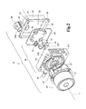
- Fig. 1 is an exploded perspective view showing a configuration of an electric pump 10 as seen from a cover 40 side.
- Fig. 2 is an exploded perspective view showing the configuration of the electric pump 10 as seen from a motor unit 20 side.
- Fig. 3 is a front view showing the configuration of the electric pump 10 as seen from the cover 40 side.
- the electric pump 10 includes the motor unit 20, a vane pump unit 30, and the cover 40 as main components.
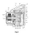
- Fig. 4 is a cross sectional view illustrating a configuration of the electric pump 10 taken along line A-A of Fig. 3 when it is seen from the side surface side.
- Fig. 5 is a cross sectional view illustrating a configuration of the electric pump 10 taken along line B-B of Fig. 3 when it is seen from the side surface side.
- the motor unit 20 includes an end cap 22, a rotation shaft 23, bearings 24, and magnets 25, which are covered by a motor cover 21.
- the rotation shaft 23 is rotatably supported at one end side by the bearing 24 (24a) attached to a bottom surface side (one end side) of the motor cover 21 and also rotatably supported by the bearing 24 (24b) attached to the end cap 22.
- a plurality of involute teeth 23a is formed at the other end side of the rotation shaft 23. That is, the rotation shaft 23 is an involute spline shaft, and a hole (spline hole 321) corresponding to the involute teeth 23a is provided at the center of a rotor 32 to be described later.
- the end cap 22 is attached to an opening side of the motor cover 21, which fits on the side of the vane pump unit 30, but a center hole 221 into which the rotation shaft 23 is inserted is provided at the center side of the end cap 22 (see Fig. 4 ). Further, a circumferential flange unit 222 protruding in a circumferential shape is provided at the center side of the end cap 22, and the bearing 24b explained above is fit into the fitting unit 223 encircled by the circumferential flange unit 222.
- a rotator 231 is attached to the rotation shaft 23, and a wire is wound around this rotator 231.
- magnets 25 are provided to face the rotator 231.
- a commutator 232 is attached to the rotation shaft 23 at the side closer to the vane pump unit 30 than the rotator 231, and the commutator 232 is disposed to be in contact with a brush 26.
- the brush 26 for providing electric power to the commutator 232 is supported by a brush support unit 233 supported by the end cap 22. Therefore, even when the commutator 232 rotates with respect to the brush 26 according to the rotation of the rotation shaft 23, the brush 26 does not follow the rotation shaft 23 and provides electric power to the commutator 232.
- the brush support unit 233 is integrally formed with the end cap 22. In the conventional configuration, the brush 26 is supported by a brush plate separate from the end cap 22, but in the present embodiment, a configuration is employed in which the brush support unit 233 having the function of the brush plate is integrally configured with the end cap 22. In the present embodiment, the end cap 22 integrally formed with the brush support unit 233 is formed by, for example, resin molding.
- the end cap 22 is integrally provided with a power supply bus bar 27.
- the power supply bus bar 27 is an elongated portion protruding from the end cap 22 toward the vane pump unit 30 side, and the cross section thereof taken in a direction perpendicular to the protruding direction is a flat shape made by connecting a pair of arcs of semicircles and a pair of straight lines.
- a lead line 28 (corresponding to wire) is present, and a portion of the lead line 28 protrudes from the end of the power supply bus bar 27.
- the lead line 28 is formed in such a manner that it is embedded in the power supply bus bar 27 by methods such as insert molding and the like, for example. Therefore, the lead line 28 electrically connecting the brush 26 and a connection unit 46 can be disposed over the entire long power supply bus bar 27.
- an insertion hole may be provided along the longitudinal direction of the power supply bus bar 27, and the lead line 28 may be inserted into the insertion hole. It should be noted that the connection unit 46 will be explained later.
- the end cap 22 of the motor unit 20 is attached to a pump plate 31, a component of the vane pump unit 30, via an O ring S1.
- the vane pump unit 30 includes not only the pump plate 31 but also the rotor 32, the vane 33, a seal S2 and the like, and the like, which will be explained later in order.
- the vane pump unit 30 is a portion functioning as a dry-type and vane-type vacuum pump not using any lubricating oil.
- the vane pump unit 30 corresponds to the pump unit.
- Fig. 6 is a side view of the electric pump 10.
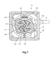
- Fig. 7 is a cross sectional view illustrating a configuration of the electric pump 10 taken along line C-C of Fig. 6 when it is seen from the front surface side (at the side of the cover 40).
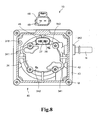
- Fig. 8 is a cross sectional view illustrating a configuration of the electric pump 10 taken along line D-D of Fig. 6 when it is seen from the front surface side (at the side of the cover 40).
- the pump plate 31 is a cam ring integrated-type plate in which each unit (for example, a cam bottom surface 315 and the like, explained later) including an external wall portion 311 and a cam ring 313 are integrally formed.
- the pump plate 31 is made of, for example, an aluminum-based member which is a material having a high degree of thermal conductivity, but may be made of other materials (for example, a steel-based member).
- aluminum-based material examples include publicly known aluminum alloys such as Al-Si-based, Al-Si-Cu-based, Al-Fe-Cu-based, and Al-Si-Fe-Cu-based alloys, and an Al-SiC composite material obtained by adding SiC powder to the aluminum or aluminum alloy.
- the entire internal configuration of the pump plate 31 is covered by the external wall portion 311 which has a substantially rectangular external appearance when seen in the top view, but this external wall portion 311 is provided with a nipple connection port unit 312 connected with a nipple N.
- the nipple connection port unit 312 is in communication with one end side of an intake path P (see Fig. 5 ) provided in the pump plate 31.
- the other end side of the intake path P is exposed in an intake chamber C2 explained later, and a gas can be introduced into the intake chamber C2.
- the cam ring 313 enclosed by the external wall portion 311 is provided.
- the cam ring 313 is a ring-shaped portion projecting from the bottom surface side (the motor unit 20 side) of the pump plate 31 toward the cover 40 side, and the inner wall surface of the cam ring 313 is a cam surface 314.
- a cam bottom surface 315 is provided at the bottom surface side in the inner space enclosed by the cam ring 313, so that the bottom surface side of the rotor 32 can be received.
- the closing plate 34 (explained later) is attached to the side of the cover 40 of the cam ring 313.
- a rotor chamber C1 which is a space closed by the cam surface 314, the cam bottom surface 315 (see Figs. 1 , 4 and 5 , and the like) and the closing plate 34 is formed.
- the cam surface 314 is provided in an oval shape, and the length in the minor axis side of the oval shape corresponds to the diameter of the rotor 32 which is a circular shape in the top view. Therefore, when the rotor 32 is arranged in the rotor chamber C1, two crescent shaped spaces (hereinafter referred to as intake chambers C2) with the short axis being the border is formed in the rotor chamber C1.
- the intake chambers C2 are in communication with the intake path P explained above, so that a gas can be introduced into this intake chamber C2.
- the cam surface 314 is formed with a coating film for improving the sliding property.
- the composition and the deposition method of the coating film are not particularly limited, but it is preferable to employ a publicly-known hard plating film.
- the hard plating film include Ni-P-X (X is at least a metal selected from W, Co, Pd, Re, Y, Mo, Ti, Mn, V, Zr, Cr, Cu, Au, Ag, Zn, Fe, Pb, Su, and Pt.
- Ni-B-X based plating film exemplified, for example, in JP 2001-192850 A
- Co-W based plating film exemplified, for example, in JP 4-94489 A
- Ni-Co-P-W based plating film exemplified, for example, in JP 4185523 B1 .
- the pump plate 31 is provided with a bulged portion 316 which is made by causing a portion of the cam ring 313 to bulge toward the external diameter side, and this bulged portion 316 is provided with a penetration hole 317.
- the penetration hole 317 is a hole through which the power supply bus bar 27 is inserted, and is configured to be in a hole shape slightly larger than the power supply bus bar 27. More specifically, even when the power supply bus bar 27 is inserted into the penetration hole 317, there is a slight gap between the power supply bus bar 27 and the inner wall surface of the penetration hole 317.
- a discharge pipe 318 is integrally formed in proximity to the inner peripheral side of the external wall portion 311 of the pump plate 31.
- the discharge pipe 318 is a portion for discharging a gas discharged to the inside of the cover 40 from communication holes 342 (explained later).
- the pump plate 31 is provided with a protruding pipe 319 in communication with the discharge pipe 318 to protrude to the side of the motor unit 20.
- the rotor 32 has a generally cylindrical appearance, but has at the center side the spline hole 321 corresponding to the above described involute teeth 23a. Rotational force of the rotation shaft 23 is transferred to the rotor 32 as the involute teeth 23a engage the spline hole 321.
- the external peripheral surface of the rotor 32 is provided with multiple vane grooves 322, and the vane 33 is movably accommodated in the vane groove 322.
- the vane groove 322 is provided in parallel to the central axial line L of the rotor 32 (see Figs.
- the vane groove 322 is not along the diameter direction of the rotor 32, and is formed in a direction such that a direction from the central side to the external peripheral side matches the direction of advancement of rotation.
- the vane 33 is disposed in the vane groove 322 explained above, and the vane 33 comes into abutment with the cam surface 314 due to the centrifugal force of the rotation of the rotor 32, so that the pressure chamber C3 is formed in the intake chamber C2.
- the pressure chamber C3 is a portion of the intake chamber C2 which is partitioned by a vane 33 and the rotor 32, or a portion thereof partitioned by adjacent vanes 33.
- the closing plate 34 is attached to the end surface of the cam ring 313 at the side of the cover 40 using screws and the like, for example, and the rotor chamber C1, which is a closed space, is formed by the attachment of the closing plate 34.
- a projection unit 341 projecting toward the cover 40 by plastic deformation of the closing plate 34 made through press work is formed on the closing plate 34.
- the projection unit 341 at the side of the motor unit 20 is a portion of the intake path P (see Fig. 5 ).
- the projection unit 341 at the side close to the rotation center is an opening portion in communication with the rotor chamber C1.
- a portion of an insertion hole P1 constituting the intake path P is formed in the cam ring 313 explained above, and the insertion hole P1 is in communication with the projection unit 341 at the side away from the rotation center.
- the insertion hole P1 is in communication with the nipple N explained above.
- the closing plate 34 is provided with the communication holes 342.
- the communication holes 342 are in communication with the intake chambers C2.
- the opening portion of the projection unit 341 is in communication with one end side of the intake chamber C2 in a crescent shape as shown in Fig. 7
- the communication hole 342 is in communication with the other end side of the intake chamber C2 in the crescent shape.
- the cover 40 is attached to the pump plate 31 with a seal S2 interposed therebetween.
- the cover 40 is a member for covering and closing the pump plate 31 opposite side to the motor unit 20.
- This cover 40 is provided with a top surface portion 41 and a side surface portion 42, and the top surface portion 41 faces the pump plate 31 with a predetermined gap therebetween.
- a flange unit 43 is provided on the side surface portion 42 at the side of the vane pump unit 30, and the flange unit 43 is in contact with the end surface of the external wall portion 311, and is fixed to the external wall portion 311 with screws M.
- multiple ribs 44 are provided to protrude from the top surface portion 41 toward the pump plate 31 side, and these ribs 44 are disposed along the vertical direction and the horizontal direction perpendicular to the central axial line L.
- Fig. 9 is is a cross sectional view illustrating a configuration of the electric pump 10 taken along line E-E of Fig. 6 when it is seen from the back surface side (the side of the motor unit 20).
- the end surface of the ribs 44 at the side of the vane pump unit 30 is a receiving surface for the resonator plate 50 as shown in Figs. 2 and 9 , and the resonator plate 50 is arranged on the receiving surface.
- small chambers C4 (see Fig. 5 ) enclosed by the top surface portion 41, the rib 44, and the resonator plate 50 are formed.
- the resonator plate 50 is formed with multiple holes 50a respectively in communication with the small chambers C4. The gas can enter there and exit therefrom through the hole 50a, and the small chamber C4 functions as a resonator using sound resonance effect.
- a connector box 45 is provided on the cover 40 in a protruding manner from the top surface portion 41 thereof toward the pump plate 31 side, and an insertion recessed portion 45a in a recessed shape is formed by being enclosed by the connector box 45.
- the power supply bus bar 27 explained above can be inserted into the insertion recessed portion 45a (see Fig. 4 ).
- the connection unit 46 electrically connected to the lead line 28 is provided in the insertion recessed portion 45a at the side of the top surface portion 41, and when the power supply bus bar 27 is inserted into the insertion recessed portion 45a, the lead line 28 is electrically connected to the connection unit 46.
- the insertion recessed portion 45a is provided in such a manner as to be positioned with the penetration hole 317 existing in the bulged portion 316.
- a grommet 51 shown in Figs. 1 , 2 , and 4 is disposed at the side of the opening of the connector box 45, and this grommet 51 is also in contact with the end surface of the bulged portion 316. As shown in Fig. 4 , the grommet 51 gets into the insertion recessed portion 45a by a predetermined amount, and the power supply bus bar 27 is inserted into the insertion recessed portion 45a via the grommet 51, and the lead line 28 is electrically connected to the connection unit 46 when inserted.
- the side surface portion 42 located in proximity to the connector box 45 is provided with an extension unit 47 extending in a direction away from the central axial line L, and a connector cover 48 extends from the extension unit 47 to return back to the motor unit 20 side in parallel with the central axial line L.
- the connector cover 48 is made in a cylindrical shape of which end portion at the side of the motor unit 20 is open, and a cable, not shown, can be inserted into this connector cover 48.
- the connector cover 48 can be formed in various shapes according to the connector shape of the vehicle to which the electric pump 10 according to the present embodiment is attached.
- a connector bus bar 49 one end side of which is electrically connected to the connection unit 46 is provided (see Fig. 4 ), the other end side of the connector bus bar 49 protrudes into the inside of the space of the connector cover 48, so that the connector bus bar 49 can be electrically connected to the inserted cable.
- the connector bus bar 49 corresponds to a conductive member.
- the rotation of the rotation shaft 23 rotates the rotor 32 counter-clockwise in Fig. 7 , and the rotation of the rotor 32 in turn applies centrifugal force on the vane 33 to cause the vane to fly out of the vane groove 322.
- the vane 33 contacts the cam surface 314, and when the vane 33 reaches the intake chamber C2, the pressure chamber C3 is formed between the vane 33 and a closest portion (the one closest portion) between the rotor 32 and the cam surface 314, or between adjacent vanes 33. Because the pressure chamber C3 increases its volume for a while as the vane 33 moves along the rotational direction of the rotor 32, a gas such as air is sucked through the opening portion of the projection unit 341.
- the pressure chamber C3 in turn decreases its volume, so that the gas inside is compressed. Accordingly, when the pressure chamber C3 communicates with the communication hole 342, a gas such as air is discharged through the communication hole 342.
- the end cap 22 is integrally provided with the power supply bus bar 27, which passes through the penetration hole 317 of the pump plate 31 and then is inserted into the insertion recessed portion 45a of the connector box 45.
- the lead line 28 protruding from the front end of the power supply bus bar 27 is electrically connected to the connection unit 46 in the insertion recessed portion 45a.
- the lead line 28 is electrically connected to the connection unit 46 which is provided at the cover 40 side.
- the electric pump 10 can meet various attachment modes and various requirements by changing designs of the cover 40 without having to change designs of the motor unit 20. That is, when a connecting portion to a connector is provided at the motor unit 20 side corresponding to various shapes of connectors, for example, in a vehicle and the like, where connectors with various shapes are used, even similar types of motor units 20 require forming different molds for molding according to the connecting portion to the connector, and also, molding the motor units 20 requires high accuracy in view of the relation with the axis of the rotation shaft 23, thereby increasing the costs accordingly.
- the connector cover 48 corresponds to such a portion. Then, shaping the connector cover 48 to correspond to various connectors can achieve commonality of motor units 20 which might even be electrically connected to various types of connectors.
- the electric pump 10 of the embodiment can easily correspond to changes in electrical configuration.
- an electric pump 10A with electrical configurations different from those of the electric pump 10 described in Figs. 1 to 9 will be described with reference to Fig. 10 .
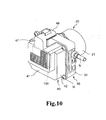
- Fig. 10 is a perspective view of the electric pump 10A having a configuration in which a controller board 100 is provided at a cover 40.
- a portion for mounting the controller board 100 is required to have a relatively large area. Accordingly, it is difficult to mount a controller board onto a conventional electric pump. As a result, the controller board is often mounted separately from the electric pump.
- the controller board 100 is provided at the top surface portion 41 of the cover 40 side.
- the top surface portion 41 is placed away from a vane pump unit 30 generating heat in a compression process, and further, the controller board 100 is provided at the top surface portion 41 side through small chambers C4 functioning as a resonator on the side away from the vane pump unit 30. Therefore, the present embodiment can suppress the influence of the heat generated in the vane pump unit 30 on the controller board 100.
- the pump plate 31 has the bulged portion 316 formed by bulging the part of the cam ring 313 toward the external diameter side, and the penetration hole 317 is provided in the bulged portion 316.
- Adoption of the configuration in which the power supply bus bar 27 is inserted through the penetration hole 317 of the bulged portion 316 as above improves guiding performance of the power supply bus bar 27, thereby preventing the power supply bus bar 27 from bending and so on until it is guided to a connection unit 46.
- presence of a little space between the power supply bus bar 27 and the inner wall surface of the penetration hole 317 allows heat generated in the compression process in a rotor chamber C1 to be released to the outside of the vane pump unit 30 through the space in the penetration hole 317.
- the provision of the bulged portion 316 increases the surface area of the cam ring 313, thereby also achieving the effect of releasing heat generated in the rotor chamber C1.
- the cover 40 is provided with the extension unit 47 and the connector cover 48.
- the external cable is inserted into the inner space of the connector cover 48.
- the connector bus bar 49 one end side of which is electrically connected to the connection unit 46 and the other end side of which protrudes into the inner space of the connector cover 48 is provided inside the extension unit 47. Therefore, the motor unit 20 is favorably provided with electric power simply by inserting an external cable into the connector cover 48.
- the electric pump 10 is of dry type not using a lubricating oil in the above embodiment, a wet type electric pump using a lubricating oil may be applied to the invention.
- the pump unit is the vane pump unit using a vane-type pump, the invention may be applied to a pump unit using pumps other than a vane-type pump.
- the above embodiment adopts the configuration in which the cover 40 is provided with the extension unit 47 protruding outwardly from the side surface portion 42, and the connector cover 48 is connected to the extension unit 47.
- the extension unit 47 may be removed and a portion corresponding to the connector cover 48 may extend from the side surface portion 42 toward the inside side of the cover 40.
- the above embodiment adopts the configuration in which one extension unit 47 extends outwardly from the side surface portion 42 of the cover 40 and one connector cover 48 is connected to the extension unit 47.
- the numbers of the extension unit 47 and the connector cover 48 are not limited to only one, and two or more extension units 47 and two or more connector covers 48 may be provided.
- a plurality of connector covers 48 corresponding to different types of cables and the same number of or less extension units 47 may be provided.
Landscapes
- Engineering & Computer Science (AREA)
- Mechanical Engineering (AREA)
- General Engineering & Computer Science (AREA)
- Transportation (AREA)
- Power Engineering (AREA)
- Applications Or Details Of Rotary Compressors (AREA)
- Rotary Pumps (AREA)
- Structures Of Non-Positive Displacement Pumps (AREA)
Abstract
Description
- The present invention relates to, for example, an electric pump for causing a negative pressure chamber of a brake booster of a vehicle to be in a negative pressure.
- A vane-type vacuum pump has been used in a vehicle such as a car and the like in order to, for example, cause a negative pressure chamber of a brake booster to be in a negative pressure. Such vane-type vacuum pumps include an electric pump powered by an electric motor.
- Such an electric pump is provided with a conductive part for providing electric power to a rotator of a motor. For example,
Patent Literatures Patent Literature 1 discloses a technique in which a housing of a pump unit is provided with a wiring hole and a wire harness is inserted through the hole while being connected to a connector at a part positioned on an opposite side of the housing from a motor.Patent Literature 2 discloses a configuration in which an intermediate connector is removably provided to a base plate. -
- [PTL 1]
JP 8-200217 A - [PTL 2]
JP 2010-236512 A - Now, removably attaching an intermediate connector to a base plate as in
Patent Literature 2 requires a space at the center side for an opening portion through which a rotation shaft is inserted. This limits a space for an electrical configuration including a connector. For example, even if the same motor is used (achieve commonality of motors), some types of electric pumps are provided with only a connector at a base plate, while others also provided with a controller board for driving the motor, and so on. The configuration disclosed inPatent Literature 2 with limited space for an electrical configuration cannot handle such various requirements. - Then, it is conceivable that a connector can be provided at the cover positioned on an opposite side of the housing from the motor as in the configuration of
Patent Literature 1. In the configuration ofPatent Literature 1, however, a flexibly moving wire harness is inserted into a wiring hole, and the configuration requires pulling the wire harness out of the wiring hole. It is also troublesome to connect the wire harness to the connector. - The present invention has been achieved in view of the above circumstances and aims to provide an electric pump that allows sufficient space for an electric configuration as well as achieving commonality of motor units.
- To solve the above problems, according to a first aspect of the present invention, provided is an electric pump, including: a motor unit including a rotation shaft, an end cap attached to an opening portion side of a motor cover, and a power supply bus bar integral with the end cap and extending toward a side away from a bottom of the motor cover; a pump unit including a rotor having a vane groove for receiving a vane and connecting to the rotation shaft and a pump plate integrally provided with an external wall portion and a cam ring on which the vane slides; and a cover covering the pump unit from a side opposite to the motor unit and provided with a connector box surrounding an insertion recessed portion into which the power supply bus bar is inserted. In the electric pump, the pump plate has a penetration hole through which the power supply bus bar can be inserted, wiring is inserted into the power supply bus bar inserted through the penetration hole, the wiring protrudes from a front end side of the penetration hole, and the wiring is electrically connected to a connection unit provided in the insertion recessed portion.
- According to another aspect of the invention, in the above invention, it is preferable that the pump plate be provided with a bulged portion formed by bulging a part of the cam ring toward an external diameter side, and the bulged portion be provided with the penetration hole.
- According to another aspect of the invention, in the above invention, it is preferable that an extension unit extending outwardly from an external wall portion of the cover be provided to the external wall portion, a connector cover be drawn from the extension unit toward the motor unit side and an external cable be inserted into an inner space of the connector cover, and a conductive member having one end side electrically connected to the connection unit and the other end side protruding into the inner space of the connector cover be provided in an inside of the extension unit.
- According to another aspect of the invention, in the above invention, it is preferable that a controller board electrically connected to the connection unit and controlling action of the rotation shaft in the motor unit be mounted onto the cover.
- An electric pump according to the present invention allows sufficient space for an electric configuration, and also achieves commonality of motor units.
-
- [
Fig. 1] Fig. 1 is an exploded perspective view showing a configuration of an electric pump according to an embodiment of the present invention as seen from a cover side. - [
Fig. 2] Fig. 2 is an exploded perspective view showing the configuration of the electric pump according to an embodiment of the present invention as seen from a motor unit side. - [
Fig. 3] Fig. 3 is a front view of the electric pump ofFig. 1 as seen from the cover side. - [
Fig. 4] Fig. 4 is a cross sectional view illustrating a configuration of electric pump taken along line A-A ofFig. 3 when it is seen from the side surface side. - [
Fig. 5] Fig. 5 is a cross sectional view illustrating a configuration of electric pump taken along line B-B ofFig. 3 when it is seen from the side surface side. - [
Fig. 6] Fig. 6 is a side view of the electric pump ofFig. 1 . - [
Fig. 7] Fig. 7 is a cross sectional view illustrating a configuration of electric pump taken along line C-C ofFig. 6 when it is seen from the front surface side (cover side). - [
Fig. 8] Fig. 8 is a cross sectional view illustrating a configuration of electric pump taken along line D-D ofFig. 6 when it is seen from the front surface side (cover side). - [
Fig. 9] Fig. 9 is a cross sectional view illustrating a configuration of electric pump taken along line E-E ofFig. 6 when it is seen from the front surface side (cover side). - [
Fig. 10] Fig. 10 is a perspective view showing a configuration of an electric pump according to a modification of the present invention. - Hereinafter, an electric pump according to an embodiment of the present invention will be described with reference to the drawings.
-
Fig. 1 is an exploded perspective view showing a configuration of anelectric pump 10 as seen from acover 40 side.Fig. 2 is an exploded perspective view showing the configuration of theelectric pump 10 as seen from amotor unit 20 side.Fig. 3 is a front view showing the configuration of theelectric pump 10 as seen from thecover 40 side. As shown inFigs. 1 to 3 , theelectric pump 10 includes themotor unit 20, avane pump unit 30, and thecover 40 as main components. -
Fig. 4 is a cross sectional view illustrating a configuration of theelectric pump 10 taken along line A-A ofFig. 3 when it is seen from the side surface side.Fig. 5 is a cross sectional view illustrating a configuration of theelectric pump 10 taken along line B-B ofFig. 3 when it is seen from the side surface side. As shown inFigs. 1 ,4 , and5 , themotor unit 20 includes anend cap 22, arotation shaft 23, bearings 24, andmagnets 25, which are covered by amotor cover 21. In more detail, therotation shaft 23 is rotatably supported at one end side by the bearing 24 (24a) attached to a bottom surface side (one end side) of themotor cover 21 and also rotatably supported by the bearing 24 (24b) attached to theend cap 22. A plurality ofinvolute teeth 23a is formed at the other end side of therotation shaft 23. That is, therotation shaft 23 is an involute spline shaft, and a hole (spline hole 321) corresponding to theinvolute teeth 23a is provided at the center of arotor 32 to be described later. - The
end cap 22 is attached to an opening side of themotor cover 21, which fits on the side of thevane pump unit 30, but acenter hole 221 into which therotation shaft 23 is inserted is provided at the center side of the end cap 22 (seeFig. 4 ). Further, acircumferential flange unit 222 protruding in a circumferential shape is provided at the center side of theend cap 22, and the bearing 24b explained above is fit into thefitting unit 223 encircled by thecircumferential flange unit 222. - A
rotator 231 is attached to therotation shaft 23, and a wire is wound around thisrotator 231. On the inner wall of themotor cover 21,magnets 25 are provided to face therotator 231. Further, acommutator 232 is attached to therotation shaft 23 at the side closer to thevane pump unit 30 than therotator 231, and thecommutator 232 is disposed to be in contact with abrush 26. - The
brush 26 for providing electric power to thecommutator 232 is supported by abrush support unit 233 supported by theend cap 22. Therefore, even when thecommutator 232 rotates with respect to thebrush 26 according to the rotation of therotation shaft 23, thebrush 26 does not follow therotation shaft 23 and provides electric power to thecommutator 232. Thebrush support unit 233 is integrally formed with theend cap 22. In the conventional configuration, thebrush 26 is supported by a brush plate separate from theend cap 22, but in the present embodiment, a configuration is employed in which thebrush support unit 233 having the function of the brush plate is integrally configured with theend cap 22. In the present embodiment, theend cap 22 integrally formed with thebrush support unit 233 is formed by, for example, resin molding. - As shown in
Figs. 1 and4 , theend cap 22 is integrally provided with a powersupply bus bar 27. The powersupply bus bar 27 is an elongated portion protruding from theend cap 22 toward thevane pump unit 30 side, and the cross section thereof taken in a direction perpendicular to the protruding direction is a flat shape made by connecting a pair of arcs of semicircles and a pair of straight lines. In the powersupply bus bar 27, a lead line 28 (corresponding to wire) is present, and a portion of thelead line 28 protrudes from the end of the powersupply bus bar 27. For example, when theend cap 22 having the powersupply bus bar 27 is resin-molded, thelead line 28 is formed in such a manner that it is embedded in the powersupply bus bar 27 by methods such as insert molding and the like, for example. Therefore, thelead line 28 electrically connecting thebrush 26 and aconnection unit 46 can be disposed over the entire long powersupply bus bar 27. However, an insertion hole may be provided along the longitudinal direction of the powersupply bus bar 27, and thelead line 28 may be inserted into the insertion hole. It should be noted that theconnection unit 46 will be explained later. - As shown in
Figs. 1 ,2 ,4 , and5 , theend cap 22 of themotor unit 20 is attached to apump plate 31, a component of thevane pump unit 30, via an O ring S1. Thevane pump unit 30 includes not only thepump plate 31 but also therotor 32, thevane 33, a seal S2 and the like, and the like, which will be explained later in order. In the present embodiment, thevane pump unit 30 is a portion functioning as a dry-type and vane-type vacuum pump not using any lubricating oil. Thevane pump unit 30 corresponds to the pump unit. -
Fig. 6 is a side view of theelectric pump 10.Fig. 7 is a cross sectional view illustrating a configuration of theelectric pump 10 taken along line C-C ofFig. 6 when it is seen from the front surface side (at the side of the cover 40).Fig. 8 is a cross sectional view illustrating a configuration of theelectric pump 10 taken along line D-D ofFig. 6 when it is seen from the front surface side (at the side of the cover 40). - As shown in
Figs. 1 and8 , thepump plate 31 is a cam ring integrated-type plate in which each unit (for example, a cambottom surface 315 and the like, explained later) including anexternal wall portion 311 and acam ring 313 are integrally formed. Moreover, thepump plate 31 is made of, for example, an aluminum-based member which is a material having a high degree of thermal conductivity, but may be made of other materials (for example, a steel-based member). Examples of aluminum-based material that can be used include publicly known aluminum alloys such as Al-Si-based, Al-Si-Cu-based, Al-Fe-Cu-based, and Al-Si-Fe-Cu-based alloys, and an Al-SiC composite material obtained by adding SiC powder to the aluminum or aluminum alloy. - As shown in
Figs. 1 and7 , the entire internal configuration of thepump plate 31 is covered by theexternal wall portion 311 which has a substantially rectangular external appearance when seen in the top view, but thisexternal wall portion 311 is provided with a nippleconnection port unit 312 connected with a nipple N. The nippleconnection port unit 312 is in communication with one end side of an intake path P (seeFig. 5 ) provided in thepump plate 31. The other end side of the intake path P is exposed in an intake chamber C2 explained later, and a gas can be introduced into the intake chamber C2. - At the central side of the
pump plate 31, thecam ring 313 enclosed by theexternal wall portion 311 is provided. Thecam ring 313 is a ring-shaped portion projecting from the bottom surface side (themotor unit 20 side) of thepump plate 31 toward thecover 40 side, and the inner wall surface of thecam ring 313 is acam surface 314. Acam bottom surface 315 is provided at the bottom surface side in the inner space enclosed by thecam ring 313, so that the bottom surface side of therotor 32 can be received. Further, the closing plate 34 (explained later) is attached to the side of thecover 40 of thecam ring 313. A rotor chamber C1 which is a space closed by thecam surface 314, the cam bottom surface 315 (seeFigs. 1 ,4 and5 , and the like) and theclosing plate 34 is formed. - As shown in
Fig. 7 , thecam surface 314 is provided in an oval shape, and the length in the minor axis side of the oval shape corresponds to the diameter of therotor 32 which is a circular shape in the top view. Therefore, when therotor 32 is arranged in the rotor chamber C1, two crescent shaped spaces (hereinafter referred to as intake chambers C2) with the short axis being the border is formed in the rotor chamber C1. The intake chambers C2 are in communication with the intake path P explained above, so that a gas can be introduced into this intake chamber C2. - Since the
electric pump 10 according to the present embodiment is dry-type not using any lubricating oil, thecam surface 314 is formed with a coating film for improving the sliding property. As long as the sliding property can be improved, the composition and the deposition method of the coating film are not particularly limited, but it is preferable to employ a publicly-known hard plating film. Examples of the hard plating film include Ni-P-X (X is at least a metal selected from W, Co, Pd, Re, Y, Mo, Ti, Mn, V, Zr, Cr, Cu, Au, Ag, Zn, Fe, Pb, Su, and Pt. The same applies hereinafter.) based plating film and Ni-B-X based plating film exemplified, for example, inJP 2001-192850 A JP 4-94489 A JP 4185523 B1 - As shown in
Figs. 1 and7 , thepump plate 31 is provided with a bulgedportion 316 which is made by causing a portion of thecam ring 313 to bulge toward the external diameter side, and this bulgedportion 316 is provided with apenetration hole 317. Thepenetration hole 317 is a hole through which the powersupply bus bar 27 is inserted, and is configured to be in a hole shape slightly larger than the powersupply bus bar 27. More specifically, even when the powersupply bus bar 27 is inserted into thepenetration hole 317, there is a slight gap between the powersupply bus bar 27 and the inner wall surface of thepenetration hole 317. Adischarge pipe 318 is integrally formed in proximity to the inner peripheral side of theexternal wall portion 311 of thepump plate 31. Thedischarge pipe 318 is a portion for discharging a gas discharged to the inside of thecover 40 from communication holes 342 (explained later). Thepump plate 31 is provided with a protrudingpipe 319 in communication with thedischarge pipe 318 to protrude to the side of themotor unit 20. - The
rotor 32 has a generally cylindrical appearance, but has at the center side thespline hole 321 corresponding to the above describedinvolute teeth 23a. Rotational force of therotation shaft 23 is transferred to therotor 32 as theinvolute teeth 23a engage thespline hole 321. The external peripheral surface of therotor 32 is provided withmultiple vane grooves 322, and thevane 33 is movably accommodated in thevane groove 322. Thevane groove 322 is provided in parallel to the central axial line L of the rotor 32 (seeFigs. 1 ,2 , and4 ), and thevane groove 322 is not along the diameter direction of therotor 32, and is formed in a direction such that a direction from the central side to the external peripheral side matches the direction of advancement of rotation. Thevane 33 is disposed in thevane groove 322 explained above, and thevane 33 comes into abutment with thecam surface 314 due to the centrifugal force of the rotation of therotor 32, so that the pressure chamber C3 is formed in the intake chamber C2. The pressure chamber C3 is a portion of the intake chamber C2 which is partitioned by avane 33 and therotor 32, or a portion thereof partitioned byadjacent vanes 33. - As shown in
Figs. 1 and8 , the closingplate 34 is attached to the end surface of thecam ring 313 at the side of thecover 40 using screws and the like, for example, and the rotor chamber C1, which is a closed space, is formed by the attachment of theclosing plate 34. Aprojection unit 341 projecting toward thecover 40 by plastic deformation of theclosing plate 34 made through press work is formed on theclosing plate 34. Theprojection unit 341 at the side of themotor unit 20 is a portion of the intake path P (seeFig. 5 ). Theprojection unit 341 at the side close to the rotation center is an opening portion in communication with the rotor chamber C1. A portion of an insertion hole P1 constituting the intake path P is formed in thecam ring 313 explained above, and the insertion hole P1 is in communication with theprojection unit 341 at the side away from the rotation center. The insertion hole P1 is in communication with the nipple N explained above. - The closing
plate 34 is provided with the communication holes 342. The communication holes 342 are in communication with the intake chambers C2. The opening portion of theprojection unit 341 is in communication with one end side of the intake chamber C2 in a crescent shape as shown inFig. 7 , and thecommunication hole 342 is in communication with the other end side of the intake chamber C2 in the crescent shape. When seen in the rotation direction of therotor 32, the external peripheral surface of therotor 32 passes in proximity to the opening portion of theprojection unit 341, and advances along the intake chamber C2 for some distance, and thereafter, comes to the vicinity of thecommunication hole 342. - As shown in
Figs. 1 and2 , thecover 40 is attached to thepump plate 31 with a seal S2 interposed therebetween. Thecover 40 is a member for covering and closing thepump plate 31 opposite side to themotor unit 20. Thiscover 40 is provided with atop surface portion 41 and aside surface portion 42, and thetop surface portion 41 faces thepump plate 31 with a predetermined gap therebetween. Aflange unit 43 is provided on theside surface portion 42 at the side of thevane pump unit 30, and theflange unit 43 is in contact with the end surface of theexternal wall portion 311, and is fixed to theexternal wall portion 311 with screws M. As shown inFig. 5 ,multiple ribs 44 are provided to protrude from thetop surface portion 41 toward thepump plate 31 side, and theseribs 44 are disposed along the vertical direction and the horizontal direction perpendicular to the central axial line L. -
Fig. 9 is is a cross sectional view illustrating a configuration of theelectric pump 10 taken along line E-E ofFig. 6 when it is seen from the back surface side (the side of the motor unit 20). The end surface of theribs 44 at the side of thevane pump unit 30 is a receiving surface for theresonator plate 50 as shown inFigs. 2 and9 , and theresonator plate 50 is arranged on the receiving surface. Accordingly, small chambers C4 (seeFig. 5 ) enclosed by thetop surface portion 41, therib 44, and theresonator plate 50 are formed. As shown inFig. 9 , theresonator plate 50 is formed withmultiple holes 50a respectively in communication with the small chambers C4. The gas can enter there and exit therefrom through thehole 50a, and the small chamber C4 functions as a resonator using sound resonance effect. - As shown in
Figs. 2 ,4 ,8 , and9 , aconnector box 45 is provided on thecover 40 in a protruding manner from thetop surface portion 41 thereof toward thepump plate 31 side, and an insertion recessedportion 45a in a recessed shape is formed by being enclosed by theconnector box 45. The powersupply bus bar 27 explained above can be inserted into the insertion recessedportion 45a (seeFig. 4 ). Theconnection unit 46 electrically connected to thelead line 28 is provided in the insertion recessedportion 45a at the side of thetop surface portion 41, and when the powersupply bus bar 27 is inserted into the insertion recessedportion 45a, thelead line 28 is electrically connected to theconnection unit 46. - The insertion recessed
portion 45a is provided in such a manner as to be positioned with thepenetration hole 317 existing in the bulgedportion 316. Agrommet 51 shown inFigs. 1 ,2 , and4 is disposed at the side of the opening of theconnector box 45, and thisgrommet 51 is also in contact with the end surface of the bulgedportion 316. As shown inFig. 4 , thegrommet 51 gets into the insertion recessedportion 45a by a predetermined amount, and the powersupply bus bar 27 is inserted into the insertion recessedportion 45a via thegrommet 51, and thelead line 28 is electrically connected to theconnection unit 46 when inserted. - As shown in
Figs. 3 ,4 ,6 ,9 , and the like, theside surface portion 42 located in proximity to theconnector box 45 is provided with anextension unit 47 extending in a direction away from the central axial line L, and aconnector cover 48 extends from theextension unit 47 to return back to themotor unit 20 side in parallel with the central axial line L. - It should be noted that the
connector cover 48 is made in a cylindrical shape of which end portion at the side of themotor unit 20 is open, and a cable, not shown, can be inserted into thisconnector cover 48. Theconnector cover 48 can be formed in various shapes according to the connector shape of the vehicle to which theelectric pump 10 according to the present embodiment is attached. - Inside of the
extension unit 47, aconnector bus bar 49 one end side of which is electrically connected to theconnection unit 46 is provided (seeFig. 4 ), the other end side of theconnector bus bar 49 protrudes into the inside of the space of theconnector cover 48, so that theconnector bus bar 49 can be electrically connected to the inserted cable. Theconnector bus bar 49 corresponds to a conductive member. - In the
electric pump 10 having the above configuration, electric power is provided from the cable via theconnector bus bar 49, theconnection unit 46, thelead line 28, thebrush 26, and thecommutator 232 to the wound wire of therotator 231, and by providing the electric power, therotator 231 and therotation shaft 23 are rotated. - Then, the rotation of the
rotation shaft 23 rotates therotor 32 counter-clockwise inFig. 7 , and the rotation of therotor 32 in turn applies centrifugal force on thevane 33 to cause the vane to fly out of thevane groove 322. Thus, thevane 33 contacts thecam surface 314, and when thevane 33 reaches the intake chamber C2, the pressure chamber C3 is formed between thevane 33 and a closest portion (the one closest portion) between therotor 32 and thecam surface 314, or betweenadjacent vanes 33. Because the pressure chamber C3 increases its volume for a while as thevane 33 moves along the rotational direction of therotor 32, a gas such as air is sucked through the opening portion of theprojection unit 341. However, as thevane 33 moves for a while toward a closest portion (the other closest portion) between therotor 32 and thecam surface 314, the pressure chamber C3 in turn decreases its volume, so that the gas inside is compressed. Accordingly, when the pressure chamber C3 communicates with thecommunication hole 342, a gas such as air is discharged through thecommunication hole 342. - When a gas enters into the
cover 40 through thecommunication hole 342, pressure fluctuations (sound wave) of the gas enters through theholes 50a. Then, at a particular frequency of the sound wave, air inside the small chambers C4 resonates, and the resonance strongly vibrates air flowing in and out of theholes 50a. This increases friction loss to give sound absorbing effect. Then, the gas discharged through thecommunication hole 342 is discharged through thedischarge pipe 318 to the outside. - According to the
electric pump 10 with the above configuration, theend cap 22 is integrally provided with the powersupply bus bar 27, which passes through thepenetration hole 317 of thepump plate 31 and then is inserted into the insertion recessedportion 45a of theconnector box 45. Thelead line 28 protruding from the front end of the powersupply bus bar 27 is electrically connected to theconnection unit 46 in the insertion recessedportion 45a. - Accordingly, the
lead line 28 is electrically connected to theconnection unit 46 which is provided at thecover 40 side. As a result, theelectric pump 10 can meet various attachment modes and various requirements by changing designs of thecover 40 without having to change designs of themotor unit 20. That is, when a connecting portion to a connector is provided at themotor unit 20 side corresponding to various shapes of connectors, for example, in a vehicle and the like, where connectors with various shapes are used, even similar types ofmotor units 20 require forming different molds for molding according to the connecting portion to the connector, and also, molding themotor units 20 requires high accuracy in view of the relation with the axis of therotation shaft 23, thereby increasing the costs accordingly. - When adopting a configuration in which the power
supply bus bar 27 protrudes from theend cap 22 and thelead line 28 protruding from the protruding end of the bus bar connects to theconnection unit 46 of thecover 40, as described above however, a portion corresponding to the connecting portion to the connector may be provided at thecover 40. In the present embodiment, theconnector cover 48 corresponds to such a portion. Then, shaping theconnector cover 48 to correspond to various connectors can achieve commonality ofmotor units 20 which might even be electrically connected to various types of connectors. - Moreover, in the present embodiment, various electrical configurations including the
connector bus bar 49 can be provided at thecover 40 which can secure sufficient space for electrical configuration. Accordingly, theelectric pump 10 of the embodiment can easily correspond to changes in electrical configuration. As a specific example, an electric pump 10A with electrical configurations different from those of theelectric pump 10 described inFigs. 1 to 9 will be described with reference toFig. 10 . -
Fig. 10 is a perspective view of the electric pump 10A having a configuration in which acontroller board 100 is provided at acover 40. When providing thecontroller board 100 incorporating a micro computer and the like for controlling action of therotation shaft 23 in themotor unit 20, a portion for mounting thecontroller board 100 is required to have a relatively large area. Accordingly, it is difficult to mount a controller board onto a conventional electric pump. As a result, the controller board is often mounted separately from the electric pump. - In contrast, in the present embodiment, because various electrical configurations including a
connector bus bar 49 can be provided at thecover 40 side which can secure sufficient space for electrical configuration, it is needless to say that thecontroller board 100 as shown inFig. 10 can be provided at thecover 40 side. Therefore, it is possible to achieve an electric pump 10A integrally incorporating thecontroller board 100, which is difficult to achieve with conventional techniques. - In the case of the electric pump 10A as shown in
Fig. 10 , thecontroller board 100 is provided at thetop surface portion 41 of thecover 40 side. Thetop surface portion 41 is placed away from avane pump unit 30 generating heat in a compression process, and further, thecontroller board 100 is provided at thetop surface portion 41 side through small chambers C4 functioning as a resonator on the side away from thevane pump unit 30. Therefore, the present embodiment can suppress the influence of the heat generated in thevane pump unit 30 on thecontroller board 100. - Moreover, in the present embodiment, the
pump plate 31 has the bulgedportion 316 formed by bulging the part of thecam ring 313 toward the external diameter side, and thepenetration hole 317 is provided in the bulgedportion 316. Adoption of the configuration in which the powersupply bus bar 27 is inserted through thepenetration hole 317 of the bulgedportion 316 as above improves guiding performance of the powersupply bus bar 27, thereby preventing the powersupply bus bar 27 from bending and so on until it is guided to aconnection unit 46. Also, presence of a little space between the powersupply bus bar 27 and the inner wall surface of thepenetration hole 317 allows heat generated in the compression process in a rotor chamber C1 to be released to the outside of thevane pump unit 30 through the space in thepenetration hole 317. Further, the provision of the bulgedportion 316 increases the surface area of thecam ring 313, thereby also achieving the effect of releasing heat generated in the rotor chamber C1. - Further, in the present embodiment, the
cover 40 is provided with theextension unit 47 and theconnector cover 48. The external cable is inserted into the inner space of theconnector cover 48. Theconnector bus bar 49 one end side of which is electrically connected to theconnection unit 46 and the other end side of which protrudes into the inner space of theconnector cover 48 is provided inside theextension unit 47. Therefore, themotor unit 20 is favorably provided with electric power simply by inserting an external cable into theconnector cover 48. - The embodiments of the present invention have been described hereinbefore. The invention however can be carried out with various modifications in addition to them. The modifications will be described hereinafter.
- Although the
electric pump 10 is of dry type not using a lubricating oil in the above embodiment, a wet type electric pump using a lubricating oil may be applied to the invention. Also, although in the embodiment the pump unit is the vane pump unit using a vane-type pump, the invention may be applied to a pump unit using pumps other than a vane-type pump. - The above embodiment adopts the configuration in which the
cover 40 is provided with theextension unit 47 protruding outwardly from theside surface portion 42, and theconnector cover 48 is connected to theextension unit 47. However, theextension unit 47 may be removed and a portion corresponding to theconnector cover 48 may extend from theside surface portion 42 toward the inside side of thecover 40. - The above embodiment adopts the configuration in which one
extension unit 47 extends outwardly from theside surface portion 42 of thecover 40 and oneconnector cover 48 is connected to theextension unit 47. However, the numbers of theextension unit 47 and theconnector cover 48 are not limited to only one, and two ormore extension units 47 and two or more connector covers 48 may be provided. For example, a plurality of connector covers 48 corresponding to different types of cables and the same number of orless extension units 47 may be provided. -
- 10, 10A ... Electric pump
- 20 ... Motor unit
- 21 ... Motor cover
- 22 ... End cap
- 23 ... Rotation shaft
- 23a ... Involute tooth
- 26 ... Brush
- 27 ... Power supply bus bar
- 28 ... Lead line (corresponding to wiring)
- 30 ... Vane pump unit (corresponding to pump unit)
- 31 ... Pump plate
- 32 ... Rotor
- 33 ... Vane
- 34 ... Closing plate
- 40 ... Cover
- 41 ... Top surface portion
- 42 ... Side surface portion
- 44 ... Rib
- 45 ... Connector box
- 45a ... Insertion recessed portion
- 46 ... Connection unit
- 47 ... Extension unit
- 48 ... Connector cover
- 49 ... Connector bus bar
- 50 ... Resonator plate
- 51 ... Grommet
- 100 ... Controller board
- 231 ... Rotator
- 232 ... Commutator
- 311 ... External wall portion
- 313 ... Cam ring
- 314 ... Cam surface
- 316 ... Bulged portion
- 317 ... Penetration hole
- 322 ... Vane groove
- 341 ... Projection unit
- 342 ... Communication hole
- C1 ... Rotor chamber
- C2 ... Intake chamber
- C3 ... Pressure chamber
- C4 ... Small chamber
Claims (4)
- An electric pump, comprising:a motor unit including a rotation shaft, an end cap attached to an opening portion side of a motor cover, and a power supply bus bar integral with the end cap and extending toward a side away from a bottom of the motor cover;a pump unit including a rotor having a vane groove for receiving a vane and connecting to the rotation shaft, and a pump plate integrally provided with an external wall portion and a cam ring on which the vane slides; anda cover covering the pump unit from a side opposite to the motor unit and provided with a connector box surrounding an insertion recessed portion into which the power supply bus bar is inserted,the pump plate having a penetration hole through which the power supply bus bar can be inserted, wiring being inserted into the power supply bus bar inserted through the penetration hole, the wiring protruding from a front end side of the penetration hole, and the wiring being electrically connected to a connection unit provided in the insertion recessed portion.
- The electric pump according to claim 1, wherein
the pump plate is provided with a bulged portion formed by bulging a part of the cam ring toward an external diameter side, and the bulged portion is provided with the penetration hole. - The electric pump according to claim 1 or 2, wherein
an extension unit extending outwardly from an external wall portion of the cover is provided to the external wall portion,
a connector cover is drawn from the extension unit and an external cable is inserted into an inner space of the connector cover, and
a conductive member having one end side electrically connected to the connection unit and the other end side protruding into the inner space of the connector cover is provided to an inside of the extension unit. - The electric pump according to any one of claims 1 to 3, wherein
a controller board electrically connected to the connection unit and controlling action of the rotation shaft in the motor unit is mounted onto the cover.
Applications Claiming Priority (2)
| Application Number | Priority Date | Filing Date | Title |
|---|---|---|---|
| JP2012166379A JP6091792B2 (en) | 2012-07-26 | 2012-07-26 | Electric pump |
| PCT/JP2013/070323 WO2014017633A1 (en) | 2012-07-26 | 2013-07-26 | Electric pump |
Publications (3)
| Publication Number | Publication Date |
|---|---|
| EP2878823A1 true EP2878823A1 (en) | 2015-06-03 |
| EP2878823A4 EP2878823A4 (en) | 2016-07-06 |
| EP2878823B1 EP2878823B1 (en) | 2017-11-15 |
Family
ID=49997438
Family Applications (1)
| Application Number | Title | Priority Date | Filing Date |
|---|---|---|---|
| EP13822373.0A Not-in-force EP2878823B1 (en) | 2012-07-26 | 2013-07-26 | Electric pump |
Country Status (5)
| Country | Link |
|---|---|
| US (1) | US9726174B2 (en) |
| EP (1) | EP2878823B1 (en) |
| JP (1) | JP6091792B2 (en) |
| CN (1) | CN104685214B (en) |
| WO (1) | WO2014017633A1 (en) |
Cited By (1)
| Publication number | Priority date | Publication date | Assignee | Title |
|---|---|---|---|---|
| WO2023036834A1 (en) * | 2021-09-10 | 2023-03-16 | Vitesco Technologies Germany Gmbh | Pump, in particular transmission oil pump, with a modular construction |
Families Citing this family (4)
| Publication number | Priority date | Publication date | Assignee | Title |
|---|---|---|---|---|
| TWI639064B (en) * | 2014-04-01 | 2018-10-21 | 日商尼康股份有限公司 | Substrate processing device and element manufacturing method |
| JP6518275B2 (en) * | 2017-02-24 | 2019-05-22 | シナノケンシ株式会社 | Electric pump |
| KR102694119B1 (en) * | 2018-09-12 | 2024-08-12 | 엘지이노텍 주식회사 | Motor |
| MX2024003446A (en) * | 2021-11-12 | 2024-04-03 | Ubukata Ind Co Ltd | DEVICE FOR FIXING ENCAPSULATED TYPE ELECTRIC COMPRESSOR AND MOTOR PROTECTOR. |
Family Cites Families (13)
| Publication number | Priority date | Publication date | Assignee | Title |
|---|---|---|---|---|
| JPH0494489A (en) | 1990-08-11 | 1992-03-26 | Kooken:Kk | Compressor |
| US5895207A (en) * | 1993-06-17 | 1999-04-20 | Itt Automotive Europe, Gmbh | Electric motor-pump assembly |
| JPH08200217A (en) * | 1995-01-23 | 1996-08-06 | Toyota Motor Corp | Electric pump and manufacturing method thereof |
| DE19949221A1 (en) * | 1999-10-13 | 2001-04-19 | Bosch Gmbh Robert | Electro-hydraulic unit for regulating a brake pressure of a hydraulic vehicle brake system |
| JP2001192850A (en) | 2000-01-11 | 2001-07-17 | Ebe Katsuo | Surface treating solution for sliding parts, surface treating method for sliding parts and sliding parts |
| JP4185523B2 (en) | 2005-12-14 | 2008-11-26 | 日本カニゼン株式会社 | Electroless nickel plating film and machine part having this film |
| JP2007318885A (en) * | 2006-05-25 | 2007-12-06 | Mabuchi Motor Co Ltd | Brushless motor |
| JP2008232134A (en) * | 2007-02-20 | 2008-10-02 | Calsonic Kansei Corp | Electric compressor |
| JP2010174851A (en) * | 2009-02-02 | 2010-08-12 | Calsonic Kansei Corp | Shaft-rotor assembly for compressor, vane rotary compressor, and method for manufacturing the shaft-rotor assembly for compressor |
| JP5129776B2 (en) * | 2009-03-31 | 2013-01-30 | 日信工業株式会社 | Electric pump |
| JP2010265833A (en) | 2009-05-15 | 2010-11-25 | Mikuni Corp | Electric pump |
| JP2011144788A (en) * | 2010-01-18 | 2011-07-28 | Toyota Industries Corp | Motor-driven compressor |
| JP2012012940A (en) * | 2010-06-29 | 2012-01-19 | Calsonic Kansei Corp | Gas compressor |
-
2012
- 2012-07-26 JP JP2012166379A patent/JP6091792B2/en not_active Expired - Fee Related
-
2013
- 2013-07-26 WO PCT/JP2013/070323 patent/WO2014017633A1/en not_active Ceased
- 2013-07-26 EP EP13822373.0A patent/EP2878823B1/en not_active Not-in-force
- 2013-07-26 US US14/417,323 patent/US9726174B2/en not_active Expired - Fee Related
- 2013-07-26 CN CN201380049750.1A patent/CN104685214B/en active Active
Cited By (2)
| Publication number | Priority date | Publication date | Assignee | Title |
|---|---|---|---|---|
| WO2023036834A1 (en) * | 2021-09-10 | 2023-03-16 | Vitesco Technologies Germany Gmbh | Pump, in particular transmission oil pump, with a modular construction |
| US12607190B2 (en) | 2021-09-10 | 2026-04-21 | Vitesco Technologies Germany Gmbh | Pump with a modular construction |
Also Published As
| Publication number | Publication date |
|---|---|
| EP2878823B1 (en) | 2017-11-15 |
| US9726174B2 (en) | 2017-08-08 |
| US20150275894A1 (en) | 2015-10-01 |
| WO2014017633A1 (en) | 2014-01-30 |
| CN104685214B (en) | 2016-10-26 |
| CN104685214A (en) | 2015-06-03 |
| EP2878823A4 (en) | 2016-07-06 |
| JP6091792B2 (en) | 2017-03-08 |
| JP2014025412A (en) | 2014-02-06 |
Similar Documents
| Publication | Publication Date | Title |
|---|---|---|
| EP2878823B1 (en) | Electric pump | |
| US10066626B2 (en) | Electric pump | |
| US20110175470A1 (en) | Motor-driven compressor | |
| KR101290863B1 (en) | Compressor | |
| EP2075470B1 (en) | Motor-driven compressor | |
| EP2692984B1 (en) | Motor-driven compressor | |
| JP6400288B2 (en) | Electric pump | |
| JP6645570B2 (en) | Electric device and electric supercharger | |
| EP2924291B1 (en) | Electric pump | |
| CN104364525B (en) | Motor compressor | |
| CN209067470U (en) | Electric oil pump | |
| CN115694048A (en) | Electric compressor | |
| JP5040818B2 (en) | Shield connector | |
| JP6601246B2 (en) | Electric compressor | |
| JP2019050711A (en) | Electric oil pump | |
| CN104251189B (en) | Motor-driven compressor | |
| EP2818706A1 (en) | Motor-driven compressor | |
| JP5861674B2 (en) | Electric compressor | |
| US20130202463A1 (en) | Motor-driven compressor | |
| WO2014017634A1 (en) | Electric pump | |
| CN110318977B (en) | Electric compressor | |
| KR20140021343A (en) | Inverter cover of motor driven compressor | |
| JP7811586B2 (en) | Electrical machinery | |
| JP2012188968A (en) | Vane pump | |
| JP2009041399A (en) | Compressor |
Legal Events
| Date | Code | Title | Description |
|---|---|---|---|
| PUAI | Public reference made under article 153(3) epc to a published international application that has entered the european phase |
Free format text: ORIGINAL CODE: 0009012 |
|
| 17P | Request for examination filed |
Effective date: 20150212 |
|
| AK | Designated contracting states |
Kind code of ref document: A1 Designated state(s): AL AT BE BG CH CY CZ DE DK EE ES FI FR GB GR HR HU IE IS IT LI LT LU LV MC MK MT NL NO PL PT RO RS SE SI SK SM TR |
|
| AX | Request for extension of the european patent |
Extension state: BA ME |
|
| DAX | Request for extension of the european patent (deleted) | ||
| RA4 | Supplementary search report drawn up and despatched (corrected) |
Effective date: 20160606 |
|
| RIC1 | Information provided on ipc code assigned before grant |
Ipc: F04C 29/00 20060101ALI20160531BHEP Ipc: F04C 18/344 20060101AFI20160531BHEP Ipc: F04C 25/02 20060101ALI20160531BHEP |
|
| GRAP | Despatch of communication of intention to grant a patent |
Free format text: ORIGINAL CODE: EPIDOSNIGR1 |
|
| RIC1 | Information provided on ipc code assigned before grant |
Ipc: H02K 5/22 20060101ALN20170424BHEP Ipc: F04C 25/02 20060101ALI20170424BHEP Ipc: F04C 18/344 20060101AFI20170424BHEP |
|
| INTG | Intention to grant announced |
Effective date: 20170518 |
|
| GRAS | Grant fee paid |
Free format text: ORIGINAL CODE: EPIDOSNIGR3 |
|
| GRAJ | Information related to disapproval of communication of intention to grant by the applicant or resumption of examination proceedings by the epo deleted |
Free format text: ORIGINAL CODE: EPIDOSDIGR1 |
|
| GRAL | Information related to payment of fee for publishing/printing deleted |
Free format text: ORIGINAL CODE: EPIDOSDIGR3 |
|
| GRAJ | Information related to disapproval of communication of intention to grant by the applicant or resumption of examination proceedings by the epo deleted |
Free format text: ORIGINAL CODE: EPIDOSDIGR1 |
|
| GRAP | Despatch of communication of intention to grant a patent |
Free format text: ORIGINAL CODE: EPIDOSNIGR1 |
|
| GRAR | Information related to intention to grant a patent recorded |
Free format text: ORIGINAL CODE: EPIDOSNIGR71 |
|
| GRAA | (expected) grant |
Free format text: ORIGINAL CODE: 0009210 |
|
| INTC | Intention to grant announced (deleted) | ||
| RIC1 | Information provided on ipc code assigned before grant |
Ipc: H02K 5/22 20060101ALN20170921BHEP Ipc: F04C 25/02 20060101ALI20170921BHEP Ipc: F04C 18/344 20060101AFI20170921BHEP |
|
| INTG | Intention to grant announced |
Effective date: 20171013 |
|
| AK | Designated contracting states |
Kind code of ref document: B1 Designated state(s): AL AT BE BG CH CY CZ DE DK EE ES FI FR GB GR HR HU IE IS IT LI LT LU LV MC MK MT NL NO PL PT RO RS SE SI SK SM TR |
|
| INTG | Intention to grant announced |
Effective date: 20171010 |
|
| REG | Reference to a national code |
Ref country code: CH Ref legal event code: EP Ref country code: GB Ref legal event code: FG4D Ref country code: AT Ref legal event code: REF Ref document number: 946579 Country of ref document: AT Kind code of ref document: T Effective date: 20171115 |
|
| RIC1 | Information provided on ipc code assigned before grant |
Ipc: H02K 5/22 20060101ALN20171006BHEP Ipc: F04C 25/02 20060101ALI20171006BHEP Ipc: F04C 18/344 20060101AFI20171006BHEP |
|
| REG | Reference to a national code |
Ref country code: IE Ref legal event code: FG4D |
|
| REG | Reference to a national code |
Ref country code: DE Ref legal event code: R096 Ref document number: 602013029587 Country of ref document: DE |
|
| REG | Reference to a national code |
Ref country code: NL Ref legal event code: MP Effective date: 20171115 |
|
| REG | Reference to a national code |
Ref country code: LT Ref legal event code: MG4D |
|
| REG | Reference to a national code |
Ref country code: AT Ref legal event code: MK05 Ref document number: 946579 Country of ref document: AT Kind code of ref document: T Effective date: 20171115 |
|
| PG25 | Lapsed in a contracting state [announced via postgrant information from national office to epo] |
Ref country code: LT Free format text: LAPSE BECAUSE OF FAILURE TO SUBMIT A TRANSLATION OF THE DESCRIPTION OR TO PAY THE FEE WITHIN THE PRESCRIBED TIME-LIMIT Effective date: 20171115 Ref country code: SE Free format text: LAPSE BECAUSE OF FAILURE TO SUBMIT A TRANSLATION OF THE DESCRIPTION OR TO PAY THE FEE WITHIN THE PRESCRIBED TIME-LIMIT Effective date: 20171115 Ref country code: FI Free format text: LAPSE BECAUSE OF FAILURE TO SUBMIT A TRANSLATION OF THE DESCRIPTION OR TO PAY THE FEE WITHIN THE PRESCRIBED TIME-LIMIT Effective date: 20171115 Ref country code: ES Free format text: LAPSE BECAUSE OF FAILURE TO SUBMIT A TRANSLATION OF THE DESCRIPTION OR TO PAY THE FEE WITHIN THE PRESCRIBED TIME-LIMIT Effective date: 20171115 Ref country code: NO Free format text: LAPSE BECAUSE OF FAILURE TO SUBMIT A TRANSLATION OF THE DESCRIPTION OR TO PAY THE FEE WITHIN THE PRESCRIBED TIME-LIMIT Effective date: 20180215 Ref country code: NL Free format text: LAPSE BECAUSE OF FAILURE TO SUBMIT A TRANSLATION OF THE DESCRIPTION OR TO PAY THE FEE WITHIN THE PRESCRIBED TIME-LIMIT Effective date: 20171115 |
|
| PG25 | Lapsed in a contracting state [announced via postgrant information from national office to epo] |
Ref country code: RS Free format text: LAPSE BECAUSE OF FAILURE TO SUBMIT A TRANSLATION OF THE DESCRIPTION OR TO PAY THE FEE WITHIN THE PRESCRIBED TIME-LIMIT Effective date: 20171115 Ref country code: GR Free format text: LAPSE BECAUSE OF FAILURE TO SUBMIT A TRANSLATION OF THE DESCRIPTION OR TO PAY THE FEE WITHIN THE PRESCRIBED TIME-LIMIT Effective date: 20180216 Ref country code: LV Free format text: LAPSE BECAUSE OF FAILURE TO SUBMIT A TRANSLATION OF THE DESCRIPTION OR TO PAY THE FEE WITHIN THE PRESCRIBED TIME-LIMIT Effective date: 20171115 Ref country code: HR Free format text: LAPSE BECAUSE OF FAILURE TO SUBMIT A TRANSLATION OF THE DESCRIPTION OR TO PAY THE FEE WITHIN THE PRESCRIBED TIME-LIMIT Effective date: 20171115 Ref country code: AT Free format text: LAPSE BECAUSE OF FAILURE TO SUBMIT A TRANSLATION OF THE DESCRIPTION OR TO PAY THE FEE WITHIN THE PRESCRIBED TIME-LIMIT Effective date: 20171115 Ref country code: BG Free format text: LAPSE BECAUSE OF FAILURE TO SUBMIT A TRANSLATION OF THE DESCRIPTION OR TO PAY THE FEE WITHIN THE PRESCRIBED TIME-LIMIT Effective date: 20180215 |
|
| REG | Reference to a national code |
Ref country code: FR Ref legal event code: PLFP Year of fee payment: 6 |
|
| PG25 | Lapsed in a contracting state [announced via postgrant information from national office to epo] |
Ref country code: SK Free format text: LAPSE BECAUSE OF FAILURE TO SUBMIT A TRANSLATION OF THE DESCRIPTION OR TO PAY THE FEE WITHIN THE PRESCRIBED TIME-LIMIT Effective date: 20171115 Ref country code: CZ Free format text: LAPSE BECAUSE OF FAILURE TO SUBMIT A TRANSLATION OF THE DESCRIPTION OR TO PAY THE FEE WITHIN THE PRESCRIBED TIME-LIMIT Effective date: 20171115 Ref country code: DK Free format text: LAPSE BECAUSE OF FAILURE TO SUBMIT A TRANSLATION OF THE DESCRIPTION OR TO PAY THE FEE WITHIN THE PRESCRIBED TIME-LIMIT Effective date: 20171115 Ref country code: CY Free format text: LAPSE BECAUSE OF FAILURE TO SUBMIT A TRANSLATION OF THE DESCRIPTION OR TO PAY THE FEE WITHIN THE PRESCRIBED TIME-LIMIT Effective date: 20171115 Ref country code: EE Free format text: LAPSE BECAUSE OF FAILURE TO SUBMIT A TRANSLATION OF THE DESCRIPTION OR TO PAY THE FEE WITHIN THE PRESCRIBED TIME-LIMIT Effective date: 20171115 |
|
| REG | Reference to a national code |
Ref country code: DE Ref legal event code: R097 Ref document number: 602013029587 Country of ref document: DE |
|
| PG25 | Lapsed in a contracting state [announced via postgrant information from national office to epo] |
Ref country code: SM Free format text: LAPSE BECAUSE OF FAILURE TO SUBMIT A TRANSLATION OF THE DESCRIPTION OR TO PAY THE FEE WITHIN THE PRESCRIBED TIME-LIMIT Effective date: 20171115 Ref country code: RO Free format text: LAPSE BECAUSE OF FAILURE TO SUBMIT A TRANSLATION OF THE DESCRIPTION OR TO PAY THE FEE WITHIN THE PRESCRIBED TIME-LIMIT Effective date: 20171115 Ref country code: PL Free format text: LAPSE BECAUSE OF FAILURE TO SUBMIT A TRANSLATION OF THE DESCRIPTION OR TO PAY THE FEE WITHIN THE PRESCRIBED TIME-LIMIT Effective date: 20171115 Ref country code: IT Free format text: LAPSE BECAUSE OF FAILURE TO SUBMIT A TRANSLATION OF THE DESCRIPTION OR TO PAY THE FEE WITHIN THE PRESCRIBED TIME-LIMIT Effective date: 20171115 |
|
| PGFP | Annual fee paid to national office [announced via postgrant information from national office to epo] |
Ref country code: FR Payment date: 20180612 Year of fee payment: 6 |
|
| PLBE | No opposition filed within time limit |
Free format text: ORIGINAL CODE: 0009261 |
|
| STAA | Information on the status of an ep patent application or granted ep patent |
Free format text: STATUS: NO OPPOSITION FILED WITHIN TIME LIMIT |
|
| 26N | No opposition filed |
Effective date: 20180817 |
|
| PG25 | Lapsed in a contracting state [announced via postgrant information from national office to epo] |
Ref country code: SI Free format text: LAPSE BECAUSE OF FAILURE TO SUBMIT A TRANSLATION OF THE DESCRIPTION OR TO PAY THE FEE WITHIN THE PRESCRIBED TIME-LIMIT Effective date: 20171115 |
|
| REG | Reference to a national code |
Ref country code: CH Ref legal event code: PL |
|
| GBPC | Gb: european patent ceased through non-payment of renewal fee |
Effective date: 20180726 |
|
| PG25 | Lapsed in a contracting state [announced via postgrant information from national office to epo] |
Ref country code: MC Free format text: LAPSE BECAUSE OF FAILURE TO SUBMIT A TRANSLATION OF THE DESCRIPTION OR TO PAY THE FEE WITHIN THE PRESCRIBED TIME-LIMIT Effective date: 20171115 Ref country code: LU Free format text: LAPSE BECAUSE OF NON-PAYMENT OF DUE FEES Effective date: 20180726 |
|
| REG | Reference to a national code |
Ref country code: BE Ref legal event code: MM Effective date: 20180731 |
|
| REG | Reference to a national code |
Ref country code: IE Ref legal event code: MM4A |
|
| PG25 | Lapsed in a contracting state [announced via postgrant information from national office to epo] |
Ref country code: CH Free format text: LAPSE BECAUSE OF NON-PAYMENT OF DUE FEES Effective date: 20180731 Ref country code: LI Free format text: LAPSE BECAUSE OF NON-PAYMENT OF DUE FEES Effective date: 20180731 Ref country code: GB Free format text: LAPSE BECAUSE OF NON-PAYMENT OF DUE FEES Effective date: 20180726 Ref country code: IE Free format text: LAPSE BECAUSE OF NON-PAYMENT OF DUE FEES Effective date: 20180726 |
|
| PG25 | Lapsed in a contracting state [announced via postgrant information from national office to epo] |
Ref country code: BE Free format text: LAPSE BECAUSE OF NON-PAYMENT OF DUE FEES Effective date: 20180731 |
|
| REG | Reference to a national code |
Ref country code: DE Ref legal event code: R082 Ref document number: 602013029587 Country of ref document: DE Representative=s name: SCHAEFER, MATTHIAS W., DIPL.-ING., DE Ref country code: DE Ref legal event code: R081 Ref document number: 602013029587 Country of ref document: DE Owner name: MIKUNI CORP., JP Free format text: FORMER OWNERS: KOKUSAN DENKI CO. LTD., NUMAZU, SHIZUOKA, JP; MIKUNI CORP., TOKIO/TOKYO, JP |
|
| PG25 | Lapsed in a contracting state [announced via postgrant information from national office to epo] |
Ref country code: MT Free format text: LAPSE BECAUSE OF NON-PAYMENT OF DUE FEES Effective date: 20180726 |
|
| PG25 | Lapsed in a contracting state [announced via postgrant information from national office to epo] |
Ref country code: TR Free format text: LAPSE BECAUSE OF FAILURE TO SUBMIT A TRANSLATION OF THE DESCRIPTION OR TO PAY THE FEE WITHIN THE PRESCRIBED TIME-LIMIT Effective date: 20171115 |
|
| PG25 | Lapsed in a contracting state [announced via postgrant information from national office to epo] |
Ref country code: HU Free format text: LAPSE BECAUSE OF FAILURE TO SUBMIT A TRANSLATION OF THE DESCRIPTION OR TO PAY THE FEE WITHIN THE PRESCRIBED TIME-LIMIT; INVALID AB INITIO Effective date: 20130726 Ref country code: PT Free format text: LAPSE BECAUSE OF FAILURE TO SUBMIT A TRANSLATION OF THE DESCRIPTION OR TO PAY THE FEE WITHIN THE PRESCRIBED TIME-LIMIT Effective date: 20171115 |
|
| PG25 | Lapsed in a contracting state [announced via postgrant information from national office to epo] |
Ref country code: FR Free format text: LAPSE BECAUSE OF NON-PAYMENT OF DUE FEES Effective date: 20190731 Ref country code: MK Free format text: LAPSE BECAUSE OF NON-PAYMENT OF DUE FEES Effective date: 20171115 |
|
| PG25 | Lapsed in a contracting state [announced via postgrant information from national office to epo] |
Ref country code: AL Free format text: LAPSE BECAUSE OF FAILURE TO SUBMIT A TRANSLATION OF THE DESCRIPTION OR TO PAY THE FEE WITHIN THE PRESCRIBED TIME-LIMIT Effective date: 20171115 Ref country code: IS Free format text: LAPSE BECAUSE OF FAILURE TO SUBMIT A TRANSLATION OF THE DESCRIPTION OR TO PAY THE FEE WITHIN THE PRESCRIBED TIME-LIMIT Effective date: 20180315 |
|
| PGFP | Annual fee paid to national office [announced via postgrant information from national office to epo] |
Ref country code: DE Payment date: 20240529 Year of fee payment: 12 |
|
| REG | Reference to a national code |
Ref country code: DE Ref legal event code: R119 Ref document number: 602013029587 Country of ref document: DE |
|
| PG25 | Lapsed in a contracting state [announced via postgrant information from national office to epo] |
Ref country code: DE Free format text: LAPSE BECAUSE OF NON-PAYMENT OF DUE FEES Effective date: 20260203 |