EP2878816A1 - Pump control device - Google Patents
Pump control device Download PDFInfo
- Publication number
- EP2878816A1 EP2878816A1 EP14773145.9A EP14773145A EP2878816A1 EP 2878816 A1 EP2878816 A1 EP 2878816A1 EP 14773145 A EP14773145 A EP 14773145A EP 2878816 A1 EP2878816 A1 EP 2878816A1
- Authority
- EP
- European Patent Office
- Prior art keywords
- pressure
- spool
- discharge
- signal
- pump
- Prior art date
- Legal status (The legal status is an assumption and is not a legal conclusion. Google has not performed a legal analysis and makes no representation as to the accuracy of the status listed.)
- Granted
Links
Images

Classifications
-
- F—MECHANICAL ENGINEERING; LIGHTING; HEATING; WEAPONS; BLASTING
- F04—POSITIVE - DISPLACEMENT MACHINES FOR LIQUIDS; PUMPS FOR LIQUIDS OR ELASTIC FLUIDS
- F04B—POSITIVE-DISPLACEMENT MACHINES FOR LIQUIDS; PUMPS
- F04B1/00—Multi-cylinder machines or pumps characterised by number or arrangement of cylinders
- F04B1/12—Multi-cylinder machines or pumps characterised by number or arrangement of cylinders having cylinder axes coaxial with, or parallel or inclined to, main shaft axis
- F04B1/26—Control
- F04B1/30—Control of machines or pumps with rotary cylinder blocks
- F04B1/306—Control of machines or pumps with rotary cylinder blocks by turning the swash plate, e.g. with fixed inclination
-
- F—MECHANICAL ENGINEERING; LIGHTING; HEATING; WEAPONS; BLASTING
- F04—POSITIVE - DISPLACEMENT MACHINES FOR LIQUIDS; PUMPS FOR LIQUIDS OR ELASTIC FLUIDS
- F04B—POSITIVE-DISPLACEMENT MACHINES FOR LIQUIDS; PUMPS
- F04B1/00—Multi-cylinder machines or pumps characterised by number or arrangement of cylinders
- F04B1/12—Multi-cylinder machines or pumps characterised by number or arrangement of cylinders having cylinder axes coaxial with, or parallel or inclined to, main shaft axis
- F04B1/26—Control
- F04B1/30—Control of machines or pumps with rotary cylinder blocks
- F04B1/32—Control of machines or pumps with rotary cylinder blocks by varying the relative positions of a swash plate and a cylinder block
- F04B1/324—Control of machines or pumps with rotary cylinder blocks by varying the relative positions of a swash plate and a cylinder block by changing the inclination of the swash plate
-
- F—MECHANICAL ENGINEERING; LIGHTING; HEATING; WEAPONS; BLASTING
- F04—POSITIVE - DISPLACEMENT MACHINES FOR LIQUIDS; PUMPS FOR LIQUIDS OR ELASTIC FLUIDS
- F04B—POSITIVE-DISPLACEMENT MACHINES FOR LIQUIDS; PUMPS
- F04B49/00—Control, e.g. of pump delivery, or pump pressure of, or safety measures for, machines, pumps, or pumping installations, not otherwise provided for, or of interest apart from, groups F04B1/00 - F04B47/00
- F04B49/002—Hydraulic systems to change the pump delivery
-
- F—MECHANICAL ENGINEERING; LIGHTING; HEATING; WEAPONS; BLASTING
- F04—POSITIVE - DISPLACEMENT MACHINES FOR LIQUIDS; PUMPS FOR LIQUIDS OR ELASTIC FLUIDS
- F04B—POSITIVE-DISPLACEMENT MACHINES FOR LIQUIDS; PUMPS
- F04B49/00—Control, e.g. of pump delivery, or pump pressure of, or safety measures for, machines, pumps, or pumping installations, not otherwise provided for, or of interest apart from, groups F04B1/00 - F04B47/00
- F04B49/08—Regulating by delivery pressure
-
- F—MECHANICAL ENGINEERING; LIGHTING; HEATING; WEAPONS; BLASTING
- F04—POSITIVE - DISPLACEMENT MACHINES FOR LIQUIDS; PUMPS FOR LIQUIDS OR ELASTIC FLUIDS
- F04B—POSITIVE-DISPLACEMENT MACHINES FOR LIQUIDS; PUMPS
- F04B49/00—Control, e.g. of pump delivery, or pump pressure of, or safety measures for, machines, pumps, or pumping installations, not otherwise provided for, or of interest apart from, groups F04B1/00 - F04B47/00
- F04B49/22—Control, e.g. of pump delivery, or pump pressure of, or safety measures for, machines, pumps, or pumping installations, not otherwise provided for, or of interest apart from, groups F04B1/00 - F04B47/00 by means of valves
Definitions
- the present invention relates to a pump control apparatus for controlling a discharge capacity of a pump.
- a conventional driving pressure source for a hydraulic device installed in a construction machine such as a hydraulic shovel may employ a swash plate type multiple piston pump that is driven to rotate by an engine.
- the piston pump includes two sets of an intake port and a discharge port, and discharges working oil from the respective discharge ports.
- JP2008-291732A discloses a pump control apparatus that controls a discharge capacity of a swash plate type multiple piston pump.
- the pump control apparatus includes a regulator that controls a tilt angle of the swash plate so that a power of the piston pump remains constant, and an average discharge pressure obtained by averaging discharge pressures led from respective discharge ports is used as a source pressure led to the regulator.
- JP2008-240518A discloses a regulator that is provided in a piston pump driven by an engine in order to control a discharge capacity of the pump in accordance with a signal pressure led thereto when a device such as an air conditioner is operated.
- a spool forming the regulator must be increased in size in response to an increase in a number of signal pressures, and as a result, the regulator increases in structural complexity.
- An object of the present invention is to provide a pump control apparatus that controls a discharge capacity of a pump using a regulator having a simple structure even when the number of signal pressures increases.
- a pump control apparatus for controlling a discharge capacity of a pump that discharges a working fluid from a plurality of discharge ports.
- the pump control apparatus includes: an actuator that varies the discharge capacity of the pump; and a regulator that regulates a control pressure led to the actuator.
- the regulator includes: a driving pressure port to which an average discharge pressure obtained by averaging respective discharge pressures of the working fluid discharged from the plurality of discharge ports is led; a source pressure port to which a high pressure side discharge pressure, which is the highest discharge pressure of the working fluid discharged from the plurality of discharge ports, is led; a signal pressure port to which a signal pressure is led; and a spool that regulates the control pressure using the high pressure side discharge pressure as a source pressure by moving upon reception of the average discharge pressure and the signal pressure, wherein a driving pressure receiving surface that receives the average discharge pressure is formed inside the spool, and a signal pressure receiving surface that receives the signal pressure is formed in an outer peripheral step portion of the spool.
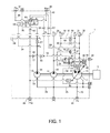
- FIG. 1 is a view showing a hydraulic circuit of a pump control apparatus 1 according to this embodiment of the present invention.
- the pump control apparatus 1 is an apparatus for driving a hydraulic device installed in a construction machine such as a hydraulic shovel, for example.
- the pump control apparatus 1 controls a discharge capacity (a pump displacement) of a variable capacity pump 11.
- variable capacity pump 11 is a swash plate type multiple piston pump, for example, that includes one intake port and two discharge ports.
- variable capacity pump 11 is driven by an engine 10 to suction working oil through the intake port from a tank port 30 connected to a tank via an intake passage 20, and discharge the working oil, which is pressurized by a piston that reciprocates so as to follow a swash plate 15, through the respective discharge ports.
- the working oil discharged from the respective discharge ports is distributed to respective hydraulic cylinders for driving a boom, an arm, and a bucket of the hydraulic shovel, left and right travel motors, and so on via a first discharge passage 21, a second discharge passage 22, pump ports 31, 32, and control valves (not shown).
- a part of the working oil is discharged from one of the discharge ports at a pressure P1 and supplied to the left travel motor through the first discharge passage 21.
- Another part of the working oil is discharged from the other discharge port at a pressure P2 and supplied to the right travel motor through the second discharge passage 22.
- the pump control apparatus 1 includes a first fixed capacity pump 12 and a second fixed capacity pump 13 that are disposed coaxially with the variable capacity pump 11.
- the first fixed capacity pump 12 and second fixed capacity pump 13 are pumps having a fixed discharge capacity, and are driven by the engine 10, which also serves as a drive source of the variable capacity pump 11.
- gear pumps are used as the first fixed capacity pump 12 and the second fixed capacity pump 13, but the embodiment is not limited thereto.
- the first fixed capacity pump 12 suctions working oil through an intake passage 25 that branches off from the intake passage 20, and delivers the pressurized working oil to a pump port 39 via a third discharge passage 23.
- This working oil is supplied via a control valve connected to the pump port 39 to a turning motor or the like for turning a cab (a driving seat) of the hydraulic shovel.
- the second fixed capacity pump 13 suctions working oil through an intake passage 26 that branches off from the intake passage 25, and delivers the pressurized working oil to a signal pressure port 34 via a signal pressure passage 24.
- This working oil is supplied through a signal pressure passage (not shown) connected to the signal pressure port 34 to a hydraulic drive unit or the like that switches the respective control valves.
- working oil is used as the working fluid that is supplied to and discharged from the variable capacity pump 11, the first fixed capacity pump 12, and the second fixed capacity pump 13.
- a working fluid such as an aqueous replacement fluid, for example, may be used instead of working oil.
- the variable capacity pump 11 which is constituted by a swash plate type piston pump, includes a cylinder block that is driven to rotate by the engine 10, a piston that reciprocates through a cylinder of the cylinder block so as to discharge the suctioned working oil, the swash plate 15 that follows the piston, horsepower control springs 48, 49 that bias a tilt angle of the swash plate 15 in an increasing direction, a small diameter actuator 47 that drives the swash plate 15 in a same direction to a spring force of the horsepower control springs 48, 49, a large diameter actuator 16 that drives the swash plate 15 against the spring force of the horsepower control springs 48, 49 and a driving force of the small diameter actuator 47, and a casing that houses these components.
- the multiple variable capacity pump 11 includes the single intake port and the two discharge ports, and in the cylinder block, a cylinder that communicates with the first discharge passage 21 and a cylinder that communicates with the second discharge passage 22 are provided.
- variable capacity pump 11 The discharge capacity of the variable capacity pump 11 is varied by driving the large diameter actuator 16 in order to vary the tilt angle of the swash plate 15, thereby varying a piston stroke of the piston that reciprocates so as to follow the swash plate 15.
- the large diameter actuator 16 reduces the tilt angle of the swash plate 15 in accordance with an increase in a control pressure Pcg led thereto.
- the discharge capacity of the variable capacity pump 11 decreases as the tilt angle of the swash plate 15 decreases.
- the pump control apparatus 1 includes a load sensing regulator 60 (referred to as an "LS regulator 60" hereafter) that regulates the control pressure Pcg led to the large diameter actuator 16, and a horsepower control regulator 40 that regulates a working oil pressure (a control pressure) Pc led to the LS regulator 60.
- LS regulator 60 load sensing regulator 60
- a horsepower control regulator 40 that regulates a working oil pressure (a control pressure) Pc led to the LS regulator 60.
- a throttle 57 is interposed in a second control pressure passage 56.
- the throttle 57 reduces pressure variation in the control pressure Pcg led to the large diameter actuator 16.
- the control pressure Pcg generated in the second control pressure passage 56 is extracted through a control pressure port 35 and detected by a pressure sensor.
- the horsepower control regulator 40 is a three-port, two-position switch valve having a spool 70 (see FIG. 2 ) that switches a position of the horsepower control regulator 40 to a position a or a position b.
- the spring force of the horsepower control springs 48, 49 is exerted on the spool 70, and an average discharge pressure Pave obtained by averaging the discharge pressure P1 and the discharge pressure P2 of the working oil discharged through the respective discharge ports is led to the spool 70 through a discharge pressure signal passage 63 as a signal pressure (a driving pressure) that counteracts the spring force.
- the spool 70 moves to a position in which the average discharge pressure Pave and the spring force of the horsepower control springs 48, 49 are counterbalanced. As a result, the position of the horsepower control regulator 40 is switched to the position a or the position b.
- the discharge pressure signal passage 63 includes a first discharge pressure signal passage 61 and a second discharge pressure signal passage 62 that branches off respectively from the first discharge passage 21 and the second discharge passage 22.
- a throttle 64 is provided in the first discharge pressure signal passage 61.
- a throttle 65 is provided in the second discharge pressure signal passage 62.
- the discharge pressure P1 generated in the first discharge passage 21 is led to the discharge pressure signal passage 63 through the throttle 64, and the discharge pressure P2 generated in the second discharge passage 22 is led to the discharge pressure signal passage 63 through the throttle 65. Accordingly, the average discharge pressure Pave serving as the average of the discharge pressure P1 and the discharge pressure P2 is generated in the discharge pressure signal passage 63. The average discharge pressure Pave is also extracted through an average discharge pressure port 32.
- the horsepower control springs 48, 49 are coupled to the spool 70 at one end and linked to the swash plate 15 at another end.
- a spring length of the horsepower control spring 49 is shorter than a spring length of the horsepower control spring 48 so that the spring force of the horsepower control springs 48, 49 increases in steps in accordance with the tilt angle of the swash plate 15 and a stroke of the spool 70.
- the horsepower control regulator 40 regulates a source pressure led to a first control pressure passage 55 from a source pressure passage 53, and a working oil pressure (a control pressure) Pc that is discharged into a low pressure passage 59 from the first control pressure passage 55 so as to be led to the LS regulator 60.
- the source pressure passage 53 includes a first source pressure passage 51 and a second source pressure passage 52 that branch off respectively from the first discharge passage 21 and the second discharge passage 22, and a high pressure selection valve 50 that generates the higher of the working oil pressure P1 generated in the first source pressure passage 51 and the working oil pressure P2 generated in the second source pressure passage 52 selectively in the source pressure passage 53.
- the higher of the working oil pressure P1 led into the first source pressure passage 51 from the first discharge passage 21 and the working oil pressure P2 led into the second source pressure passage 52 from the second discharge passage 22 is extracted by the high pressure selection valve 50, and led to the horsepower control regulator 40 and the small diameter actuator 47 through the source pressure passage 53.
- the horsepower control regulator 40 regulates the working oil pressure Pc such that a signal pressure based on the average discharge pressure Pave and the spring force of the horsepower control springs 48, 49 are counterbalanced.
- a signal pressure passage 29 that branches off from the third discharge passage 23 is connected to the horsepower control regulator 40, and a discharge pressure (referred to hereafter as a "second signal pressure") P3 of the first fixed capacity pump 12, which is led to the spool 70 through the signal pressure passage 29, acts on the horsepower control regulator 40 in a direction that counteracts the spring force.
- the second signal pressure P3 is also extracted through a second signal pressure port 39.
- an external signal pressure passage 28 is connected to the horsepower control regulator 40, and a horsepower control signal pressure Pi led to the horsepower control regulator 40 through the external signal pressure passage 28 acts on the spool 70 in a same direction to the spring force.
- the horsepower control signal pressure Pi increases, the spool 70 of the horsepower control regulator 40 moves in a direction for switching to the position b, leading to a reduction in the working oil pressure Pc.
- the LS regulator 60 is a three-port, two-position switch valve that includes a spool for switching the position of the LS regulator 60 to a position c or a position d.
- a signal pressure Pps generated on an upstream side of the control valve is led to one end of a spool of the LS regulator 60 from a signal port 36 through a signal passage 43.
- a signal pressure Pls generated on a downstream side of the control valve is led to another end of the spool of the LS regulator 60 from a signal pressure port 37 through a signal passage 44. Furthermore, a spring force of an LS spring 14 is exerted on the other end of the spool of the LS regulator 60.
- the spool of the LS regulator 60 moves to a position in which an LS differential pressure (Pps-Pls) generated before and after the control valve and the spring force of the LS spring 14 exerted on the other end of the spool are counterbalanced. As a result, the position of the LS regulator 60 is switched to the position c or the position d.
- Pps-Pls LS differential pressure
- the LS differential pressure (Pps-Pls) decreases as a result, the spool of the LS regulator 60 is held in the position c by the spring force of the LS spring 14, as shown in FIG. 1 .
- the first control pressure passage 55 connected to the horsepower control regulator 40 communicates with the second control pressure passage 56 connected to the large diameter actuator 16, and therefore the control pressure Pcg led to the large diameter actuator 16 from the LS regulator 60 takes a value based on the value Pc regulated by the horsepower control regulator 40.
- the signal pressure (the load pressure) Pls decreases.
- the LS differential pressure (Pps-Pls) increases as a result, the spool of the LS regulator 60 is moved in a direction for switching to the position d against the spring force of the LS spring 14.
- the source pressure passage 54 branching off from the second discharge passage 22, to which the discharge pressure P2 is led communicates with the second control pressure passage 56 connected to the large diameter actuator 16, and as a result, the control pressure Pcg increases.
- the LS regulator 60 regulates the control pressure Pcg led to the large diameter actuator 16 so that the LS differential pressure and the spring force of the LS spring 14 are counterbalanced.
- the discharge capacity of the variable capacity pump 11 is controlled such that the LS differential pressure (Pps-Pls) remains substantially constant irrespective of variation in the load on the hydraulic cylinders.
- a throttle 66 is provided in the first control pressure passage 55, and a throttle 67 is provided in the source pressure passage 54. As a result, pressure variation in the source pressure led to the LS regulator 60 is reduced.
- a control pressure connecting passage 69 communicates with the first control pressure passage 55 and the second control pressure passage 56.
- a throttle 18 and a check valve 17 are provided in the control pressure connecting passage 69.
- the check valve 17 is closed in a normal condition where the control pressure Pcg in the second control pressure passage 56 is higher than the working oil pressure Pc in the first control pressure passage 55.
- the check valve 17 opens such that the working oil pressure Pc in the first control pressure passage 55 is led to the large diameter actuator 16 through the second control pressure passage 56 that bypasses the LS regulator 60.
- the pump control apparatus 1 includes a regulating mechanism for increasing a discharge flow rate of the variable capacity pump 11 in accordance with an increase in a pump rotation speed of the second fixed capacity pump 13.
- the regulating mechanism is constituted by a throttle 27 interposed in the signal pressure passage 24 through which the working oil discharged from the second fixed capacity pump 13 is led, and a control pressure actuator 90 that drives the spool of the LS regulator 60 in accordance with a front-rear differential pressure of the throttle 27.
- An upstream pressure P4 of the throttle 27 in the signal pressure passage 24 is led to the control pressure actuator 90 through an upstream side control pressure connecting passage 94, and a downstream pressure P5 of the throttle 27 is led to the control pressure actuator 90 through a downstream side control pressure connecting passage 95.
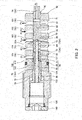
- FIG. 2 is a sectional view of the horsepower control regulator 40 according to this embodiment of the present invention.
- the horsepower control regulator 40 includes a tubular housing 100 having a spool housing hole 110, and the columnar spool 70, which is housed in the spool housing hole 110 to be free to slide.
- the housing 100 is attached to the casing of the variable capacity pump 11.
- the spool 70 has a tip end portion that projects from an open end of the spool housing hole 110, and a spring bearing is attached to the tip end portion.
- the horsepower control springs 48, 49 are interposed between the spring bearing and a feedback pin that moves in conjunction with the swash plate 15 of the variable capacity pump 11.
- a plug 140 is screwed, and thereby attached, to a base end portion of the housing 100.
- the spool 70 is biased in a direction heading toward the plug 140 (a leftward direction in FIG. 2 ) by the horsepower control springs 48, 49 such that the base end thereof impinges on the plug 140, and as a result, the stroke of the spool 70 is restricted.
- a back pressure chamber 130 is formed between the housing 100, the base end portion of the spool 70, and the plug 140.
- the back pressure chamber 130 communicates with the interior (on a tank side) of the casing of the variable capacity pump 11 through a through hole.
- An axial hole 79 extending in an axial direction is formed as an opening in the base end of the spool 70.
- a stepped columnar pin 96 is housed in the axial hole 79 to be free to slide.
- the pin 96 includes a large diameter pin portion 98 that impinges on the plug 140, a small diameter pin portion 97 that is thinner than the large diameter pin portion 98, and a pin outer peripheral step portion 99 formed between the large diameter pin portion 98 and the small diameter pin portion 97.
- the housing 100 includes five ports 101 to 105.
- the ports 101 to 105 extend in a radial direction of the spool 70 and open into the spool housing hole 110.
- the ports 101 to 105 communicate respectively with the passages 55, 53, 63, 29, 28 (see FIG. 1 ) described above via respective annular grooves formed in an outer periphery of the spool 70.
- a control pressure port 101 constitutes the first control pressure passage 55.
- the working oil pressure (control pressure) Pc that is led to the large diameter actuator 16 via the LS regulator 60 in response to an operation of the spool 70 is generated in the control pressure port 101.
- a source pressure port 102 constitutes the source pressure passage 53.
- the higher of the discharge pressures P1, P2 of the first discharge passage 21 and the second discharge passage 22 is led to the source pressure port 102.
- a driving pressure port 103 constitutes the discharge pressure signal passage 63.
- the average discharge pressure Pave obtained by averaging the discharge pressures P1, P2 of the working fluid discharged from the respective discharge ports of the variable capacity pump 11 is led to the driving pressure port 103.
- a second signal pressure port 104 constitutes the signal pressure passage 29.
- the pressure P3 of the working oil supplied to the turning motor from the first fixed capacity pump 12 is led to the second signal pressure port 104.
- a first signal pressure port 105 constitutes the external signal pressure passage 28.
- the horsepower control signal pressure Pi used to switch an operating mode is led to the first signal pressure port 105.
- a tank pressure port connecting hole 71, a driving pressure port connecting hole 72, and a second signal pressure connecting hole 73 are formed in the spool 70.
- These port connecting holes 71 to 73 extend in the radial direction of the spool 70, and respective ends thereof on both sides open onto annular grooves formed in the outer periphery of the spool 70.
- a tank pressure port 74 is formed in the tip end portion of the spool 70.
- the tank pressure port 74 extends in the axial direction of the spool 70 such that one end thereof opens into the tank pressure port connecting hole 71, and another end opens at the tip end of the spool 70 so as to communicate with the interior (on the tank side) of the casing of the variable capacity pump 11.
- the tank pressure port 74 discharges the working oil pressure Pc into the casing.
- the land portions 81, 82 open the tank pressure port connecting hole 71 and the source pressure port 102 selectively onto the spool housing hole 110, and as a result, the working oil pressure (control pressure) generated in the control pressure port 101 is regulated.
- the land portion 81 blocks communication between the tank pressure port connecting hole 71 and the control pressure port 101, and the land portion 82 blocks communication between the source pressure port 102 and the control pressure port 101.
- the tank pressure port connecting hole 71 communicates with the control pressure port 101, and as a result, the working oil pressure Pc is discharged into the case so as to decrease.
- the land portion 82 blocks communication between the source pressure port 102 and the control pressure port 101.
- the source pressure port 102 and the control pressure port 101 communicate such that the higher of the discharge pressures P1, P2 led to the source pressure passage 53 is led to the LS regulator 60 through the first control pressure passage 55.
- the working oil pressure Pc increases.
- the land portion 81 blocks communication between the tank pressure port connecting hole 71 and the control pressure port 101.
- the driving pressure port connecting hole 72 and the driving pressure port 103 communicate with each other at all times, regardless of the position of the spool 70.
- the land portion 83 blocks communication between the driving pressure port 103 and the source pressure port 102, and the land portion 84 blocks communication between the driving pressure port 103 and the second signal pressure port 104.
- a tip end 95A of the pin 96 projecting from the open end of the axial hole 79 faces a center of the driving pressure port connecting hole 72.
- a site on an inner wall surface of the driving pressure port connecting hole 72 that opposes the tip end 95A of the pin 96 constitutes a driving pressure receiving surface 72A.
- the driving pressure receiving surface 72A has a pressure receiving surface area that corresponds to a sectional area of the small diameter pin portion 97.
- a recessed portion 89 is formed in the site on the inner wall surface of the driving pressure port connecting hole 72 that opposes the tip end 95A of the pin 96.
- the recessed portion 89 is formed coaxially with the axial hole 79 so that the tip end 95A of the pin 96 does not interfere with the spool 70.
- a second signal pressure chamber 121 is defined between the axial hole 79 and the pin 96.
- the second signal pressure chamber 121, the second signal pressure port connecting hole 73, and the second signal pressure port 104 communicate with each other at all times, regardless of the position of the spool 70.
- a land portion 85 blocks communication between the second signal pressure port 104 and the first signal pressure port 105.
- the pin outer peripheral step portion 99 of the pin 96 faces the second signal pressure chamber 121, and a site on an inner wall surface of the second signal pressure port connecting hole 73 that opposes the pin outer peripheral step portion 99 of the pin 96 constitutes a second signal pressure receiving surface 73A.
- the second signal pressure receiving surface 73A has a pressure receiving surface area that corresponds to a sectional area difference between the small diameter pin portion 97 and the large diameter pin portion 98.
- the spool 70 is moved in the rightward direction of FIG. 2 by the second signal pressure P3 received by the second signal pressure receiving surface 73A, and as a result, the tip end portion of the spool 70 is pushed out of the housing 100.
- the spool 70 includes a small diameter spool portion 77, a large diameter spool portion 76 that is thicker than the small diameter spool portion 77, and an outer peripheral step portion 78 formed therebetween.
- the spool housing hole 110 of the housing 100 includes a small diameter hole portion 111 into which the small diameter spool portion 77 is inserted, and a large diameter hole portion 112 into which the large diameter spool portion 76 is inserted.
- a first signal pressure chamber 120 is defined between the large diameter hole portion 112 of the housing 100 and the spool 70.
- the first signal pressure chamber 120 and the first signal pressure port 105 communicate with each other at all times, regardless of the position of the spool 70.
- a land portion 86 blocks communication between the first signal pressure chamber 120 and the back pressure chamber 130.
- the outer peripheral step portion 78 of the spool 70 faces the first signal pressure chamber 120, and a site corresponding to a sectional area difference between the small diameter spool portion 77 and the large diameter spool portion 76 constitutes a first signal pressure receiving surface 78A.
- the spool 70 is moved in the leftward direction of FIG. 2 by the horsepower control signal pressure Pi received by the first signal pressure receiving surface 78A.
- the horsepower control regulator 40 regulates the working oil pressure Pc such that a signal pressure based on the average discharge pressure Pave and the spring force of the horsepower control springs 48, 49 are counterbalanced. Even after the rotation speed of the variable capacity pump 11 is increased, when the average discharge pressure Pave increases, the control pressure Pcg led through the LS regulator 60 is increased by the operation of the horsepower control regulator 40, and as a result, the discharge capacity of the variable capacity pump 11 decreases.
- a control system of the hydraulic shovel is switched between a high load mode (a normal operation mode) in which the engine 10 is operated at a predetermined rated rotation speed and a low load mode (a fuel saving operation mode) in which the engine 10 is operated at a lower rotation speed than the rated rotation speed.
- the horsepower control signal pressure Pi is increased in the high load mode and reduced in the low load mode.
- a mode switch is performed in response to a switch operation or the like performed by a driver, but is not limited thereto, and may be performed automatically when an air conditioner or the like is operated or the vehicle is stopped.
- the horsepower control signal pressure Pi is reduced such that a force generated by the horsepower control signal pressure Pi received by the first signal pressure receiving surface 78A decreases, and therefore the spool 70 moves in a direction for switching the position of the horsepower control regulator 40 to the position a.
- the working oil pressure Pc in the control pressure port 101 increases, leading to a reduction in the discharge capacity of the variable capacity pump 11.
- the working oil pressure P3 supplied to the turning motor from the first fixed capacity pump 12 increases.
- the second signal pressure P3 received by the second signal pressure receiving surface 73A increases, and therefore the spool 70 moves in a direction for switching the position of the horsepower control regulator 40 to the position a.
- the working oil pressure Pc in the control pressure port 101 increases, leading to a reduction in the discharge capacity of the variable capacity pump 11.
- FIG. 3 is a characteristic diagram showing a relationship between the signal pressures Pave, Pi, P3 and the discharge capacity of the variable capacity pump 11.
- the discharge capacity of the variable capacity pump 11 decreases. Accordingly, the power (horsepower) of the variable capacity pump 11 is regulated so as to remain substantially constant, and therefore an operation can be performed smoothly even when the rotation speed of the engine 10 is varied.
- the discharge capacity of the variable capacity pump 11 is reduced in comparison with the high load mode by the operation of the horsepower control regulator 40 in response to the horsepower control signal pressure Pi. Accordingly, the power of the variable capacity pump 11 decreases, leading to a reduction in the load exerted on the engine 10 that drives the variable capacity pump 11.
- the discharge capacity of the variable capacity pump 11 is reduced by the operation of the horsepower control regulator 40 in response to the second signal pressure P3 from the first fixed capacity pump 12. Accordingly, the power of the variable capacity pump 11 decreases further, leading to a further reduction in the load exerted on the engine 10 that drives the variable capacity pump 11.
- the horsepower control regulator 40 includes: the driving pressure port 103 to which the average discharge pressure Pave obtained by averaging the discharge pressures P1, P2 of the working fluid discharged from the plurality of discharge ports is led; the source pressure port 102 to which the high pressure side discharge pressure P1, P2, which is the highest discharge pressure of the working fluid discharged from the plurality of discharge ports, is led; the signal pressure port 105 to which the horsepower control signal pressure Pi is led; and the spool 70 that regulates the control pressure Pc using the high pressure side discharge pressure P1, P2 as a source pressure by moving upon reception of the average discharge pressure Pave and the horsepower control signal pressure Pi, wherein the driving pressure receiving surface 72A that receives the average discharge pressure Pave is formed inside the spool 70, and the signal pressure receiving surface 78A that receives the horsepower control signal pressure Pi is formed in the outer peripheral step portion 78 of the spool 70.
- the spool 70 of the horsepower control regulator 40 moves when the average discharge pressure Pave obtained by averaging the discharge pressures P1, P2 of the working fluid discharged through the plurality of discharge ports in the variable capacity pump 11 is received by the driving pressure receiving surface 72A formed inside the spool 70, thereby regulating the control pressure Pc led to the large diameter actuator 16 using the highest of the discharge pressures P1, P2 of the working fluid discharged through the plurality of discharge ports as a source pressure.
- the spool 70 also regulates the control pressure Pc by moving when the horsepower control signal pressure Pi is received by the signal pressure receiving surface 78A of the outer peripheral step portion 78.
- the pump control apparatus 1 configuring the pump control apparatus 1 to include the driving pressure receiving surface 72A inside the spool 70, the power of the variable capacity pump 11 can be controlled in accordance with the discharge pressure P1, P2 and the horsepower control signal pressure Pi of the variable capacity pump 11 using the simply structured horsepower control regulator 40 without increasing the size of the spool 70.
- a regulator in which a plurality of outer peripheral step portions are formed in the spool and driving pressure receiving surfaces for receiving the discharge pressures P1, P2 are formed respectively in the outer peripheral step portions may be considered as a comparative example. Further, use of a regulator in which a plurality of pin members that move in conjunction with the spool are provided and driving pressure receiving surfaces for receiving the discharge pressures P1, P2 are formed respectively on the pin members may be considered as another comparative example.
- the driving pressure receiving surface 72A that receives the average discharge pressure Pave obtained by averaging the discharge pressures P1, P2 is provided inside the spool 70, thereby eliminating the need to form a plurality of outer peripheral step portions for receiving the discharge pressures P1, P2, and as a result, an increase in the size of the spool 70 can be suppressed. Furthermore, there is no need to provide a plurality of pin members that move in conjunction with the spool 70 in the horsepower control regulator 40, and therefore the horsepower control regulator 40 can be realized with a simple structure.
- the horsepower control regulator 40 further includes: the driving pressure port connecting hole 72 formed inside the spool 70 so as to communicate with the driving pressure port 103; the axial hole 79 formed inside the spool 70 and connected to the driving pressure port connecting hole 72; and the pin 96 that is inserted into the axial hole 79 to be free to slide, and the site on the inner wall surface of the driving pressure port connecting hole 72 that opposes the pin 96 constitutes the driving pressure receiving surface 72A.
- the pin 96 is housed inside the spool 70, and the driving pressure receiving surface 72A is provided to oppose the pin 96. Therefore, an increase in the size of the horsepower control regulator 40 in the axial direction of the spool 70 caused by the driving pressure receiving surface 72A can be suppressed.
- the horsepower control regulator 40 further includes: the second signal pressure port 104 to which the second signal pressure P3, which is different from the horsepower control signal pressure Pi, is led; and the second signal pressure port connecting hole 73 formed inside the spool 70 so as to communicate with the axial hole 79 and the second signal pressure port 104.
- the pin outer peripheral step portion 99 is formed in an intermediate portion of the pin 96, and the site on the inner wall surface of the second signal pressure port connecting hole 73 that opposes the pin outer peripheral step portion 99 constitutes the second signal pressure receiving surface 73A that receives the second signal pressure P3.
- the second signal pressure receiving surface 73A that receives the second signal pressure P3 is provided to face the pin outer peripheral step portion 99 of the pin 96, and therefore an increase in the size of the horsepower control regulator 40 in the axial direction of the spool 70 caused by the second signal pressure receiving surface 73A can be suppressed.
- the pump control apparatus 1 increases the horsepower control signal pressure Pi received by the outer peripheral step portion 78 of the spool 70 such that the spool 70 moves in the direction for increasing the discharge capacity of the variable capacity pump 11.
- the pump control apparatus 1 reduces the horsepower control signal pressure Pi received by the outer peripheral step portion 78 of the spool 70 such that the spool 70 moves in the direction for reducing the discharge capacity of the variable capacity pump 11.
- the pump control apparatus 1 is not limited to a construction machine such as a hydraulic shovel, and may also be used as a fluid pressure supply source provided in another machine or facility.
Landscapes
- Engineering & Computer Science (AREA)
- Mechanical Engineering (AREA)
- General Engineering & Computer Science (AREA)
- Fluid-Pressure Circuits (AREA)
- Control Of Positive-Displacement Pumps (AREA)
- Operation Control Of Excavators (AREA)
- Reciprocating Pumps (AREA)
Abstract
Description
- The present invention relates to a pump control apparatus for controlling a discharge capacity of a pump.
- A conventional driving pressure source for a hydraulic device installed in a construction machine such as a hydraulic shovel, for example, may employ a swash plate type multiple piston pump that is driven to rotate by an engine. The piston pump includes two sets of an intake port and a discharge port, and discharges working oil from the respective discharge ports.
-
JP2008-291732A -
JP2008-240518A - In this type of conventional pump control apparatus, however, a spool forming the regulator must be increased in size in response to an increase in a number of signal pressures, and as a result, the regulator increases in structural complexity.
- An object of the present invention is to provide a pump control apparatus that controls a discharge capacity of a pump using a regulator having a simple structure even when the number of signal pressures increases.
- According to an aspect of the present invention, a pump control apparatus for controlling a discharge capacity of a pump that discharges a working fluid from a plurality of discharge ports is provided. The pump control apparatus includes: an actuator that varies the discharge capacity of the pump; and a regulator that regulates a control pressure led to the actuator. The regulator includes: a driving pressure port to which an average discharge pressure obtained by averaging respective discharge pressures of the working fluid discharged from the plurality of discharge ports is led; a source pressure port to which a high pressure side discharge pressure, which is the highest discharge pressure of the working fluid discharged from the plurality of discharge ports, is led; a signal pressure port to which a signal pressure is led; and a spool that regulates the control pressure using the high pressure side discharge pressure as a source pressure by moving upon reception of the average discharge pressure and the signal pressure, wherein a driving pressure receiving surface that receives the average discharge pressure is formed inside the spool, and a signal pressure receiving surface that receives the signal pressure is formed in an outer peripheral step portion of the spool.
-
-
FIG. 1 is a view showing a hydraulic circuit of a pump control apparatus according to an embodiment of the present invention. -
FIG. 2 is a sectional view showing a regulator according to this embodiment of the present invention. -
FIG. 3 is a characteristic diagram showing a relationship between a signal pressure and a discharge capacity in the pump control apparatus according to this embodiment of the present invention. - An embodiment of the present invention will be described below with reference to the figures and so on.
-
FIG. 1 is a view showing a hydraulic circuit of a pump control apparatus 1 according to this embodiment of the present invention. - The pump control apparatus 1 is an apparatus for driving a hydraulic device installed in a construction machine such as a hydraulic shovel, for example. The pump control apparatus 1 controls a discharge capacity (a pump displacement) of a
variable capacity pump 11. - The
variable capacity pump 11 is a swash plate type multiple piston pump, for example, that includes one intake port and two discharge ports. - The
variable capacity pump 11 is driven by anengine 10 to suction working oil through the intake port from atank port 30 connected to a tank via anintake passage 20, and discharge the working oil, which is pressurized by a piston that reciprocates so as to follow aswash plate 15, through the respective discharge ports. - The working oil discharged from the respective discharge ports is distributed to respective hydraulic cylinders for driving a boom, an arm, and a bucket of the hydraulic shovel, left and right travel motors, and so on via a
first discharge passage 21, asecond discharge passage 22,pump ports - A part of the working oil is discharged from one of the discharge ports at a pressure P1 and supplied to the left travel motor through the
first discharge passage 21. Another part of the working oil is discharged from the other discharge port at a pressure P2 and supplied to the right travel motor through thesecond discharge passage 22. By regulating flow rates of the working oil supplied to the left and right travel motors using respective control valves for the left and right travel motors, the vehicle is stopped, caused to travel forward, and turned. - The pump control apparatus 1 includes a first
fixed capacity pump 12 and a secondfixed capacity pump 13 that are disposed coaxially with thevariable capacity pump 11. The firstfixed capacity pump 12 and secondfixed capacity pump 13 are pumps having a fixed discharge capacity, and are driven by theengine 10, which also serves as a drive source of thevariable capacity pump 11. In this embodiment, gear pumps are used as the firstfixed capacity pump 12 and the secondfixed capacity pump 13, but the embodiment is not limited thereto. - The first
fixed capacity pump 12 suctions working oil through anintake passage 25 that branches off from theintake passage 20, and delivers the pressurized working oil to apump port 39 via athird discharge passage 23. This working oil is supplied via a control valve connected to thepump port 39 to a turning motor or the like for turning a cab (a driving seat) of the hydraulic shovel. - The second
fixed capacity pump 13 suctions working oil through anintake passage 26 that branches off from theintake passage 25, and delivers the pressurized working oil to a signal pressure port 34 via asignal pressure passage 24. This working oil is supplied through a signal pressure passage (not shown) connected to the signal pressure port 34 to a hydraulic drive unit or the like that switches the respective control valves. - In this embodiment, working oil (oil) is used as the working fluid that is supplied to and discharged from the
variable capacity pump 11, the firstfixed capacity pump 12, and the secondfixed capacity pump 13. However, a working fluid such as an aqueous replacement fluid, for example, may be used instead of working oil. - Next, a configuration for controlling the discharge capacity of the
variable capacity pump 11 will be described. - The
variable capacity pump 11, which is constituted by a swash plate type piston pump, includes a cylinder block that is driven to rotate by theengine 10, a piston that reciprocates through a cylinder of the cylinder block so as to discharge the suctioned working oil, theswash plate 15 that follows the piston,horsepower control springs swash plate 15 in an increasing direction, asmall diameter actuator 47 that drives theswash plate 15 in a same direction to a spring force of thehorsepower control springs large diameter actuator 16 that drives theswash plate 15 against the spring force of thehorsepower control springs small diameter actuator 47, and a casing that houses these components. - Further, the multiple
variable capacity pump 11 includes the single intake port and the two discharge ports, and in the cylinder block, a cylinder that communicates with thefirst discharge passage 21 and a cylinder that communicates with thesecond discharge passage 22 are provided. - The discharge capacity of the
variable capacity pump 11 is varied by driving thelarge diameter actuator 16 in order to vary the tilt angle of theswash plate 15, thereby varying a piston stroke of the piston that reciprocates so as to follow theswash plate 15. - The
large diameter actuator 16 reduces the tilt angle of theswash plate 15 in accordance with an increase in a control pressure Pcg led thereto. The discharge capacity of thevariable capacity pump 11 decreases as the tilt angle of theswash plate 15 decreases. - The pump control apparatus 1 includes a load sensing regulator 60 (referred to as an "
LS regulator 60" hereafter) that regulates the control pressure Pcg led to thelarge diameter actuator 16, and ahorsepower control regulator 40 that regulates a working oil pressure (a control pressure) Pc led to theLS regulator 60. - A
throttle 57 is interposed in a secondcontrol pressure passage 56. Thethrottle 57 reduces pressure variation in the control pressure Pcg led to thelarge diameter actuator 16. The control pressure Pcg generated in the secondcontrol pressure passage 56 is extracted through acontrol pressure port 35 and detected by a pressure sensor. - The
horsepower control regulator 40 is a three-port, two-position switch valve having a spool 70 (seeFIG. 2 ) that switches a position of thehorsepower control regulator 40 to a position a or a position b. - The spring force of the
horsepower control springs spool 70, and an average discharge pressure Pave obtained by averaging the discharge pressure P1 and the discharge pressure P2 of the working oil discharged through the respective discharge ports is led to thespool 70 through a dischargepressure signal passage 63 as a signal pressure (a driving pressure) that counteracts the spring force. Thespool 70 moves to a position in which the average discharge pressure Pave and the spring force of thehorsepower control springs horsepower control regulator 40 is switched to the position a or the position b. - The discharge
pressure signal passage 63 includes a first dischargepressure signal passage 61 and a second dischargepressure signal passage 62 that branches off respectively from thefirst discharge passage 21 and thesecond discharge passage 22. Athrottle 64 is provided in the first dischargepressure signal passage 61. Athrottle 65 is provided in the second dischargepressure signal passage 62. - The discharge pressure P1 generated in the
first discharge passage 21 is led to the dischargepressure signal passage 63 through thethrottle 64, and the discharge pressure P2 generated in thesecond discharge passage 22 is led to the dischargepressure signal passage 63 through thethrottle 65. Accordingly, the average discharge pressure Pave serving as the average of the discharge pressure P1 and the discharge pressure P2 is generated in the dischargepressure signal passage 63. The average discharge pressure Pave is also extracted through an averagedischarge pressure port 32. - The
horsepower control springs spool 70 at one end and linked to theswash plate 15 at another end. A spring length of thehorsepower control spring 49 is shorter than a spring length of thehorsepower control spring 48 so that the spring force of thehorsepower control springs swash plate 15 and a stroke of thespool 70. - The
horsepower control regulator 40 regulates a source pressure led to a firstcontrol pressure passage 55 from asource pressure passage 53, and a working oil pressure (a control pressure) Pc that is discharged into alow pressure passage 59 from the firstcontrol pressure passage 55 so as to be led to theLS regulator 60. - The
source pressure passage 53 includes a firstsource pressure passage 51 and a secondsource pressure passage 52 that branch off respectively from thefirst discharge passage 21 and thesecond discharge passage 22, and a highpressure selection valve 50 that generates the higher of the working oil pressure P1 generated in the firstsource pressure passage 51 and the working oil pressure P2 generated in the secondsource pressure passage 52 selectively in thesource pressure passage 53. - Hence, the higher of the working oil pressure P1 led into the first
source pressure passage 51 from thefirst discharge passage 21 and the working oil pressure P2 led into the secondsource pressure passage 52 from thesecond discharge passage 22 is extracted by the highpressure selection valve 50, and led to thehorsepower control regulator 40 and thesmall diameter actuator 47 through thesource pressure passage 53. - The
horsepower control regulator 40 regulates the working oil pressure Pc such that a signal pressure based on the average discharge pressure Pave and the spring force of thehorsepower control springs - A
signal pressure passage 29 that branches off from thethird discharge passage 23 is connected to thehorsepower control regulator 40, and a discharge pressure (referred to hereafter as a "second signal pressure") P3 of the firstfixed capacity pump 12, which is led to thespool 70 through thesignal pressure passage 29, acts on thehorsepower control regulator 40 in a direction that counteracts the spring force. The second signal pressure P3 is also extracted through a secondsignal pressure port 39. - Hence, when a load of the first
fixed capacity pump 12 for driving the turning motor increases, the second signal pressure P3 increases, and accordingly, thespool 70 of thehorsepower control regulator 40 moves in a direction for switching to the position a, leading to an increase in the working oil pressure Pc. - Further, an external
signal pressure passage 28 is connected to thehorsepower control regulator 40, and a horsepower control signal pressure Pi led to thehorsepower control regulator 40 through the externalsignal pressure passage 28 acts on thespool 70 in a same direction to the spring force. Hence, when the horsepower control signal pressure Pi increases, thespool 70 of thehorsepower control regulator 40 moves in a direction for switching to the position b, leading to a reduction in the working oil pressure Pc. - The
LS regulator 60 is a three-port, two-position switch valve that includes a spool for switching the position of theLS regulator 60 to a position c or a position d. - A signal pressure Pps generated on an upstream side of the control valve is led to one end of a spool of the
LS regulator 60 from asignal port 36 through asignal passage 43. - A signal pressure Pls generated on a downstream side of the control valve is led to another end of the spool of the
LS regulator 60 from asignal pressure port 37 through asignal passage 44. Furthermore, a spring force of anLS spring 14 is exerted on the other end of the spool of theLS regulator 60. - The spool of the
LS regulator 60 moves to a position in which an LS differential pressure (Pps-Pls) generated before and after the control valve and the spring force of theLS spring 14 exerted on the other end of the spool are counterbalanced. As a result, the position of theLS regulator 60 is switched to the position c or the position d. - For example, when a load on the respective hydraulic cylinders for driving the boom, the arm, and the bucket, and so on is large, the signal pressure (a load pressure) Pls led to the
signal pressure port 37 from the downstream side (a load side) of the control valve increases. When the LS differential pressure (Pps-Pls) decreases as a result, the spool of theLS regulator 60 is held in the position c by the spring force of theLS spring 14, as shown inFIG. 1 . In the position c, the firstcontrol pressure passage 55 connected to thehorsepower control regulator 40 communicates with the secondcontrol pressure passage 56 connected to thelarge diameter actuator 16, and therefore the control pressure Pcg led to thelarge diameter actuator 16 from theLS regulator 60 takes a value based on the value Pc regulated by thehorsepower control regulator 40. - When, on the other hand, the load on the respective hydraulic cylinders for driving the boom, the arm, and the bucket, and so on is small, the signal pressure (the load pressure) Pls decreases. When the LS differential pressure (Pps-Pls) increases as a result, the spool of the
LS regulator 60 is moved in a direction for switching to the position d against the spring force of theLS spring 14. In the position d, the source pressure passage 54 branching off from thesecond discharge passage 22, to which the discharge pressure P2 is led, communicates with the secondcontrol pressure passage 56 connected to thelarge diameter actuator 16, and as a result, the control pressure Pcg increases. - Hence, the
LS regulator 60 regulates the control pressure Pcg led to thelarge diameter actuator 16 so that the LS differential pressure and the spring force of theLS spring 14 are counterbalanced. As a result, the discharge capacity of thevariable capacity pump 11 is controlled such that the LS differential pressure (Pps-Pls) remains substantially constant irrespective of variation in the load on the hydraulic cylinders. - A throttle 66 is provided in the first
control pressure passage 55, and a throttle 67 is provided in the source pressure passage 54. As a result, pressure variation in the source pressure led to theLS regulator 60 is reduced. - A control
pressure connecting passage 69 communicates with the firstcontrol pressure passage 55 and the secondcontrol pressure passage 56. Athrottle 18 and acheck valve 17 are provided in the controlpressure connecting passage 69. - The
check valve 17 is closed in a normal condition where the control pressure Pcg in the secondcontrol pressure passage 56 is higher than the working oil pressure Pc in the firstcontrol pressure passage 55. When the control pressure Pcg decreases below the working oil pressure Pc by more than a predetermined value, however, thecheck valve 17 opens such that the working oil pressure Pc in the firstcontrol pressure passage 55 is led to thelarge diameter actuator 16 through the secondcontrol pressure passage 56 that bypasses theLS regulator 60. - The pump control apparatus 1 includes a regulating mechanism for increasing a discharge flow rate of the
variable capacity pump 11 in accordance with an increase in a pump rotation speed of the secondfixed capacity pump 13. The regulating mechanism is constituted by athrottle 27 interposed in thesignal pressure passage 24 through which the working oil discharged from the secondfixed capacity pump 13 is led, and acontrol pressure actuator 90 that drives the spool of theLS regulator 60 in accordance with a front-rear differential pressure of thethrottle 27. - An upstream pressure P4 of the
throttle 27 in thesignal pressure passage 24 is led to thecontrol pressure actuator 90 through an upstream side controlpressure connecting passage 94, and a downstream pressure P5 of thethrottle 27 is led to thecontrol pressure actuator 90 through a downstream side controlpressure connecting passage 95. - When the front-rear differential pressure (P4-P5) of the
throttle 27 increases in response to an increase in the pump rotation speed of the secondfixed capacity pump 13, a piston of thecontrol pressure actuator 90 that receives the front-rear differential pressure moves in a direction for switching the spool of theLS regulator 60 to the position c. Accordingly, the control pressure Pcg led to thelarge diameter actuator 16 from theLS regulator 60 decreases, and the discharge capacity of thevariable capacity pump 11 increases in accordance with the operation of thelarge diameter actuator 16. - Next, a specific configuration of the
horsepower control regulator 40 will be described. -
FIG. 2 is a sectional view of thehorsepower control regulator 40 according to this embodiment of the present invention. - As shown in
FIG. 2 , thehorsepower control regulator 40 includes atubular housing 100 having aspool housing hole 110, and thecolumnar spool 70, which is housed in thespool housing hole 110 to be free to slide. Thehousing 100 is attached to the casing of thevariable capacity pump 11. - The
spool 70 has a tip end portion that projects from an open end of thespool housing hole 110, and a spring bearing is attached to the tip end portion. The horsepower control springs 48, 49 (seeFIG. 1 ) are interposed between the spring bearing and a feedback pin that moves in conjunction with theswash plate 15 of thevariable capacity pump 11. - A
plug 140 is screwed, and thereby attached, to a base end portion of thehousing 100. Thespool 70 is biased in a direction heading toward the plug 140 (a leftward direction inFIG. 2 ) by the horsepower control springs 48, 49 such that the base end thereof impinges on theplug 140, and as a result, the stroke of thespool 70 is restricted. - A back pressure chamber 130 is formed between the
housing 100, the base end portion of thespool 70, and theplug 140. The back pressure chamber 130 communicates with the interior (on a tank side) of the casing of thevariable capacity pump 11 through a through hole. - An
axial hole 79 extending in an axial direction is formed as an opening in the base end of thespool 70. A steppedcolumnar pin 96 is housed in theaxial hole 79 to be free to slide. - A base end of the
pin 96 impinges on theplug 140 such that movement of thepin 96 in the leftward direction ofFIG. 2 is restricted. Thepin 96 includes a large diameter pin portion 98 that impinges on theplug 140, a small diameter pin portion 97 that is thinner than the large diameter pin portion 98, and a pin outer peripheral step portion 99 formed between the large diameter pin portion 98 and the small diameter pin portion 97. - The
housing 100 includes fiveports 101 to 105. Theports 101 to 105 extend in a radial direction of thespool 70 and open into thespool housing hole 110. Theports 101 to 105 communicate respectively with thepassages FIG. 1 ) described above via respective annular grooves formed in an outer periphery of thespool 70. - A
control pressure port 101 constitutes the firstcontrol pressure passage 55. The working oil pressure (control pressure) Pc that is led to thelarge diameter actuator 16 via theLS regulator 60 in response to an operation of thespool 70 is generated in thecontrol pressure port 101. - A
source pressure port 102 constitutes thesource pressure passage 53. The higher of the discharge pressures P1, P2 of thefirst discharge passage 21 and thesecond discharge passage 22 is led to thesource pressure port 102. - A driving
pressure port 103 constitutes the dischargepressure signal passage 63. The average discharge pressure Pave obtained by averaging the discharge pressures P1, P2 of the working fluid discharged from the respective discharge ports of thevariable capacity pump 11 is led to the drivingpressure port 103. - A second
signal pressure port 104 constitutes thesignal pressure passage 29. The pressure P3 of the working oil supplied to the turning motor from the firstfixed capacity pump 12 is led to the secondsignal pressure port 104. - A first
signal pressure port 105 constitutes the externalsignal pressure passage 28. The horsepower control signal pressure Pi used to switch an operating mode is led to the firstsignal pressure port 105. - A tank pressure port connecting hole 71, a driving pressure port connecting hole 72, and a second signal pressure connecting hole 73 are formed in the
spool 70. These port connecting holes 71 to 73 extend in the radial direction of thespool 70, and respective ends thereof on both sides open onto annular grooves formed in the outer periphery of thespool 70. - A
tank pressure port 74 is formed in the tip end portion of thespool 70. Thetank pressure port 74 extends in the axial direction of thespool 70 such that one end thereof opens into the tank pressure port connecting hole 71, and another end opens at the tip end of thespool 70 so as to communicate with the interior (on the tank side) of the casing of thevariable capacity pump 11. Thetank pressure port 74 discharges the working oil pressure Pc into the casing. - Six annularly projecting land portions 81 to 86 are formed on the outer periphery of the
spool 70. Respective outer peripheries of the land portions 81 to 86 slide against an inner periphery of thespool housing hole 110. - When the
spool 70 moves in the axial direction so as to switch between the position a and the position b, the land portions 81, 82 open the tank pressure port connecting hole 71 and thesource pressure port 102 selectively onto thespool housing hole 110, and as a result, the working oil pressure (control pressure) generated in thecontrol pressure port 101 is regulated. - In a condition where the
spool 70 is between the position a and the position b, the land portion 81 blocks communication between the tank pressure port connecting hole 71 and thecontrol pressure port 101, and the land portion 82 blocks communication between thesource pressure port 102 and thecontrol pressure port 101. - When the
spool 70 is in the position b, as shown inFIG. 2 , the tank pressure port connecting hole 71 communicates with thecontrol pressure port 101, and as a result, the working oil pressure Pc is discharged into the case so as to decrease. At this time, the land portion 82 blocks communication between thesource pressure port 102 and thecontrol pressure port 101. - When the
spool 70 moves in a rightward direction inFIG. 2 so as to switch to the position a, thesource pressure port 102 and thecontrol pressure port 101 communicate such that the higher of the discharge pressures P1, P2 led to thesource pressure passage 53 is led to theLS regulator 60 through the firstcontrol pressure passage 55. As a result, the working oil pressure Pc increases. At this time, the land portion 81 blocks communication between the tank pressure port connecting hole 71 and thecontrol pressure port 101. - The driving pressure port connecting hole 72 and the driving
pressure port 103 communicate with each other at all times, regardless of the position of thespool 70. The land portion 83 blocks communication between the drivingpressure port 103 and thesource pressure port 102, and the land portion 84 blocks communication between the drivingpressure port 103 and the secondsignal pressure port 104. - A
tip end 95A of thepin 96 projecting from the open end of theaxial hole 79 faces a center of the driving pressure port connecting hole 72. A site on an inner wall surface of the driving pressure port connecting hole 72 that opposes thetip end 95A of thepin 96 constitutes a drivingpressure receiving surface 72A. The drivingpressure receiving surface 72A has a pressure receiving surface area that corresponds to a sectional area of the small diameter pin portion 97. Thespool 70 is moved in the rightward direction ofFIG. 2 by the average discharge pressure Pave received by the drivingpressure receiving surface 72A, and as a result, the tip end portion of thespool 70 is pushed out of thehousing 100. - A recessed portion 89 is formed in the site on the inner wall surface of the driving pressure port connecting hole 72 that opposes the
tip end 95A of thepin 96. The recessed portion 89 is formed coaxially with theaxial hole 79 so that thetip end 95A of thepin 96 does not interfere with thespool 70. - A second signal pressure chamber 121 is defined between the
axial hole 79 and thepin 96. The second signal pressure chamber 121, the second signal pressure port connecting hole 73, and the secondsignal pressure port 104 communicate with each other at all times, regardless of the position of thespool 70. A land portion 85 blocks communication between the secondsignal pressure port 104 and the firstsignal pressure port 105. - The pin outer peripheral step portion 99 of the
pin 96 faces the second signal pressure chamber 121, and a site on an inner wall surface of the second signal pressure port connecting hole 73 that opposes the pin outer peripheral step portion 99 of thepin 96 constitutes a second signalpressure receiving surface 73A. The second signalpressure receiving surface 73A has a pressure receiving surface area that corresponds to a sectional area difference between the small diameter pin portion 97 and the large diameter pin portion 98. Thespool 70 is moved in the rightward direction ofFIG. 2 by the second signal pressure P3 received by the second signalpressure receiving surface 73A, and as a result, the tip end portion of thespool 70 is pushed out of thehousing 100. - The
spool 70 includes a small diameter spool portion 77, a largediameter spool portion 76 that is thicker than the small diameter spool portion 77, and an outerperipheral step portion 78 formed therebetween. - The
spool housing hole 110 of thehousing 100 includes a smalldiameter hole portion 111 into which the small diameter spool portion 77 is inserted, and a largediameter hole portion 112 into which the largediameter spool portion 76 is inserted. - A first signal pressure chamber 120 is defined between the large
diameter hole portion 112 of thehousing 100 and thespool 70. The first signal pressure chamber 120 and the firstsignal pressure port 105 communicate with each other at all times, regardless of the position of thespool 70. A land portion 86 blocks communication between the first signal pressure chamber 120 and the back pressure chamber 130. - The outer
peripheral step portion 78 of thespool 70 faces the first signal pressure chamber 120, and a site corresponding to a sectional area difference between the small diameter spool portion 77 and the largediameter spool portion 76 constitutes a first signalpressure receiving surface 78A. Thespool 70 is moved in the leftward direction ofFIG. 2 by the horsepower control signal pressure Pi received by the first signalpressure receiving surface 78A. - Next, an operation of the
horsepower control regulator 40 will be described. - As shown in
FIG. 2 , when a force generated by the average discharge pressure Pave received by the drivingpressure receiving surface 72A of thespool 70 is smaller than the spring force of the horsepower control springs 48, 49, thespool 70 moves such that thehorsepower control regulator 40 is positioned in the position b. In the position b, the working oil pressure Pc is discharged from thecontrol pressure port 101 into thetank pressure port 74 and thus reduced. - When the force generated by the average discharge pressure Pave received by the driving
pressure receiving surface 72A of thespool 70 becomes greater than the spring force of the horsepower control springs 48, 49, on the other hand, thespool 70 moves in the rightward direction ofFIG. 2 so that thehorsepower control regulator 40 switches position to the position a. In the position a, the higher of the working oil pressures P1, P2 is led to thecontrol pressure port 101 from thesource pressure port 102 such that the working oil pressure Pc in thecontrol pressure port 101 increases. - Hence, the
horsepower control regulator 40 regulates the working oil pressure Pc such that a signal pressure based on the average discharge pressure Pave and the spring force of the horsepower control springs 48, 49 are counterbalanced. Even after the rotation speed of thevariable capacity pump 11 is increased, when the average discharge pressure Pave increases, the control pressure Pcg led through theLS regulator 60 is increased by the operation of thehorsepower control regulator 40, and as a result, the discharge capacity of thevariable capacity pump 11 decreases. - A control system of the hydraulic shovel is switched between a high load mode (a normal operation mode) in which the
engine 10 is operated at a predetermined rated rotation speed and a low load mode (a fuel saving operation mode) in which theengine 10 is operated at a lower rotation speed than the rated rotation speed. The horsepower control signal pressure Pi is increased in the high load mode and reduced in the low load mode. A mode switch is performed in response to a switch operation or the like performed by a driver, but is not limited thereto, and may be performed automatically when an air conditioner or the like is operated or the vehicle is stopped. - During an operation to switch from the high load mode to the low load mode, in the
horsepower control regulator 40, the horsepower control signal pressure Pi is reduced such that a force generated by the horsepower control signal pressure Pi received by the first signalpressure receiving surface 78A decreases, and therefore thespool 70 moves in a direction for switching the position of thehorsepower control regulator 40 to the position a. As a result, the working oil pressure Pc in thecontrol pressure port 101 increases, leading to a reduction in the discharge capacity of thevariable capacity pump 11. - Further, when the turning motor is operated to turn the cab, the working oil pressure P3 supplied to the turning motor from the first
fixed capacity pump 12 increases. In thehorsepower control regulator 40 at this time, the second signal pressure P3 received by the second signalpressure receiving surface 73A increases, and therefore thespool 70 moves in a direction for switching the position of thehorsepower control regulator 40 to the position a. As a result, the working oil pressure Pc in thecontrol pressure port 101 increases, leading to a reduction in the discharge capacity of thevariable capacity pump 11. -
FIG. 3 is a characteristic diagram showing a relationship between the signal pressures Pave, Pi, P3 and the discharge capacity of thevariable capacity pump 11. - When the average discharge pressure Pave increases as a result of the operation of the
horsepower control regulator 40, the discharge capacity of thevariable capacity pump 11 decreases. Accordingly, the power (horsepower) of thevariable capacity pump 11 is regulated so as to remain substantially constant, and therefore an operation can be performed smoothly even when the rotation speed of theengine 10 is varied. In the low load mode, the discharge capacity of thevariable capacity pump 11 is reduced in comparison with the high load mode by the operation of thehorsepower control regulator 40 in response to the horsepower control signal pressure Pi. Accordingly, the power of thevariable capacity pump 11 decreases, leading to a reduction in the load exerted on theengine 10 that drives thevariable capacity pump 11. During an operation of the turning motor, the discharge capacity of thevariable capacity pump 11 is reduced by the operation of thehorsepower control regulator 40 in response to the second signal pressure P3 from the firstfixed capacity pump 12. Accordingly, the power of thevariable capacity pump 11 decreases further, leading to a further reduction in the load exerted on theengine 10 that drives thevariable capacity pump 11. - According to the embodiment described above, following actions and effects are obtained.
- (1) The
horsepower control regulator 40 includes: the drivingpressure port 103 to which the average discharge pressure Pave obtained by averaging the discharge pressures P1, P2 of the working fluid discharged from the plurality of discharge ports is led; thesource pressure port 102 to which the high pressure side discharge pressure P1, P2, which is the highest discharge pressure of the working fluid discharged from the plurality of discharge ports, is led; thesignal pressure port 105 to which the horsepower control signal pressure Pi is led; and thespool 70 that regulates the control pressure Pc using the high pressure side discharge pressure P1, P2 as a source pressure by moving upon reception of the average discharge pressure Pave and the horsepower control signal pressure Pi, wherein the drivingpressure receiving surface 72A that receives the average discharge pressure Pave is formed inside thespool 70, and the signalpressure receiving surface 78A that receives the horsepower control signal pressure Pi is formed in the outerperipheral step portion 78 of thespool 70. - Hence, the
spool 70 of thehorsepower control regulator 40 moves when the average discharge pressure Pave obtained by averaging the discharge pressures P1, P2 of the working fluid discharged through the plurality of discharge ports in thevariable capacity pump 11 is received by the drivingpressure receiving surface 72A formed inside thespool 70, thereby regulating the control pressure Pc led to thelarge diameter actuator 16 using the highest of the discharge pressures P1, P2 of the working fluid discharged through the plurality of discharge ports as a source pressure. Thespool 70 also regulates the control pressure Pc by moving when the horsepower control signal pressure Pi is received by the signalpressure receiving surface 78A of the outerperipheral step portion 78. Therefore, by configuring the pump control apparatus 1 to include the drivingpressure receiving surface 72A inside thespool 70, the power of thevariable capacity pump 11 can be controlled in accordance with the discharge pressure P1, P2 and the horsepower control signal pressure Pi of thevariable capacity pump 11 using the simply structuredhorsepower control regulator 40 without increasing the size of thespool 70. - Use of a regulator in which a plurality of outer peripheral step portions are formed in the spool and driving pressure receiving surfaces for receiving the discharge pressures P1, P2 are formed respectively in the outer peripheral step portions may be considered as a comparative example. Further, use of a regulator in which a plurality of pin members that move in conjunction with the spool are provided and driving pressure receiving surfaces for receiving the discharge pressures P1, P2 are formed respectively on the pin members may be considered as another comparative example. In contrast to these comparative examples, the driving
pressure receiving surface 72A that receives the average discharge pressure Pave obtained by averaging the discharge pressures P1, P2 is provided inside thespool 70, thereby eliminating the need to form a plurality of outer peripheral step portions for receiving the discharge pressures P1, P2, and as a result, an increase in the size of thespool 70 can be suppressed. Furthermore, there is no need to provide a plurality of pin members that move in conjunction with thespool 70 in thehorsepower control regulator 40, and therefore thehorsepower control regulator 40 can be realized with a simple structure. - (2) The
horsepower control regulator 40 further includes: the driving pressure port connecting hole 72 formed inside thespool 70 so as to communicate with the drivingpressure port 103; theaxial hole 79 formed inside thespool 70 and connected to the driving pressure port connecting hole 72; and thepin 96 that is inserted into theaxial hole 79 to be free to slide, and the site on the inner wall surface of the driving pressure port connecting hole 72 that opposes thepin 96 constitutes the drivingpressure receiving surface 72A. - Hence, the
pin 96 is housed inside thespool 70, and the drivingpressure receiving surface 72A is provided to oppose thepin 96. Therefore, an increase in the size of thehorsepower control regulator 40 in the axial direction of thespool 70 caused by the drivingpressure receiving surface 72A can be suppressed. - (3) The
horsepower control regulator 40 further includes: the secondsignal pressure port 104 to which the second signal pressure P3, which is different from the horsepower control signal pressure Pi, is led; and the second signal pressure port connecting hole 73 formed inside thespool 70 so as to communicate with theaxial hole 79 and the secondsignal pressure port 104. Further, the pin outer peripheral step portion 99 is formed in an intermediate portion of thepin 96, and the site on the inner wall surface of the second signal pressure port connecting hole 73 that opposes the pin outer peripheral step portion 99 constitutes the second signalpressure receiving surface 73A that receives the second signal pressure P3. - Hence, the second signal
pressure receiving surface 73A that receives the second signal pressure P3 is provided to face the pin outer peripheral step portion 99 of thepin 96, and therefore an increase in the size of thehorsepower control regulator 40 in the axial direction of thespool 70 caused by the second signalpressure receiving surface 73A can be suppressed. - (4) In the high load mode where the load of the
engine 10 that drives thevariable capacity pump 11 is high, the pump control apparatus 1 increases the horsepower control signal pressure Pi received by the outerperipheral step portion 78 of thespool 70 such that thespool 70 moves in the direction for increasing the discharge capacity of thevariable capacity pump 11. In the low load mode where the load of theengine 10 is low, the pump control apparatus 1 reduces the horsepower control signal pressure Pi received by the outerperipheral step portion 78 of thespool 70 such that thespool 70 moves in the direction for reducing the discharge capacity of thevariable capacity pump 11. - Hence, when the
spool 70 is moved by the reduced horsepower control signal pressure Pi in response to a switch from the high load mode to the low load mode, the discharge capacity of thevariable capacity pump 11 is reduced. In the low load mode, the horsepower control signal pressure Pi decreases, and therefore a driving load of the firstfixed capacity pump 12 is reduced, leading to a reduction in an energy consumption of the pump control apparatus 1. - An embodiment of the present invention was described above, but the above embodiment is merely one example of an application of the present invention, and the technical scope of the present invention is not limited to the specific configurations of the above embodiment.
- For example, the pump control apparatus 1 is not limited to a construction machine such as a hydraulic shovel, and may also be used as a fluid pressure supply source provided in another machine or facility.
- This application claims priority based on
Tokugan 2013-66851
Claims (4)
- A pump control apparatus for controlling a discharge capacity of a pump that discharges a working fluid through a plurality of discharge ports, comprising:an actuator that varies the discharge capacity of the pump; anda regulator that regulates a control pressure led to the actuator,the regulator comprising:a driving pressure port to which an average discharge pressure obtained by averaging respective discharge pressures of the working fluid discharged from the plurality of discharge ports is led;a source pressure port to which a high pressure side discharge pressure, which is the highest discharge pressure of the working fluid discharged from the plurality of discharge ports, is led;a signal pressure port to which a signal pressure is led; anda spool that regulates the control pressure using the high pressure side discharge pressure as a source pressure by moving upon reception of the average discharge pressure and the signal pressure,wherein a driving pressure receiving surface that receives the average discharge pressure is formed inside the spool, anda signal pressure receiving surface that receives the signal pressure is formed in an outer peripheral step portion of the spool.
- The pump control apparatus as defined in Claim 1, wherein the regulator further comprises:a driving pressure port connecting hole formed inside the spool so as to communicate with the driving pressure port;an axial hole formed inside the spool and connected to the driving pressure port connecting hole; anda pin that is inserted into the axial hole to be free to slide,wherein a site on an inner wall surface of the driving pressure port connecting hole that opposes the pin constitutes the driving pressure receiving surface.
- The pump control apparatus as defined in Claim 1, wherein the regulator further comprises:a second signal pressure port to which a second signal pressure, which is different from the signal pressure, is led; anda second signal pressure port connecting hole formed inside the spool so as to communicate with the axial hole and the second signal pressure port,wherein a pin outer peripheral step portion is formed in an intermediate portion of the pin, anda site on an inner wall surface of the second signal pressure port connecting hole that opposes the pin outer peripheral step portion constitutes a second signal pressure receiving surface that receives the second signal pressure.
- The pump control apparatus as defined in Claim 1, wherein, in a high load mode where a load of a drive source that drives the pump is high, the pump control apparatus increases the signal pressure received by the outer peripheral step portion of the spool such that the spool moves in a direction for increasing the discharge capacity of the pump, and
in a low load mode where the load of the drive source is low, the pump control apparatus reduces the signal pressure received by the outer peripheral step portion of the spool such that the spool moves in a direction for reducing the discharge capacity of the pump.
Applications Claiming Priority (2)
| Application Number | Priority Date | Filing Date | Title |
|---|---|---|---|
| JP2013066851A JP6075866B2 (en) | 2013-03-27 | 2013-03-27 | Pump control device |
| PCT/JP2014/054303 WO2014156415A1 (en) | 2013-03-27 | 2014-02-24 | Pump control device |
Publications (3)
| Publication Number | Publication Date |
|---|---|
| EP2878816A1 true EP2878816A1 (en) | 2015-06-03 |
| EP2878816A4 EP2878816A4 (en) | 2016-05-04 |
| EP2878816B1 EP2878816B1 (en) | 2018-04-18 |
Family
ID=51623412
Family Applications (1)
| Application Number | Title | Priority Date | Filing Date |
|---|---|---|---|
| EP14773145.9A Active EP2878816B1 (en) | 2013-03-27 | 2014-02-24 | Pump control device |
Country Status (6)
| Country | Link |
|---|---|
| US (1) | US20150139824A1 (en) |
| EP (1) | EP2878816B1 (en) |
| JP (1) | JP6075866B2 (en) |
| KR (1) | KR101675659B1 (en) |
| CN (1) | CN104302910B (en) |
| WO (1) | WO2014156415A1 (en) |
Families Citing this family (6)
| Publication number | Priority date | Publication date | Assignee | Title |
|---|---|---|---|---|
| KR101702253B1 (en) * | 2013-03-27 | 2017-02-03 | 케이와이비 가부시키가이샤 | Pump discharge flow-rate control device |
| JP6248144B2 (en) * | 2016-06-08 | 2017-12-13 | Kyb株式会社 | Pump device |
| DE102016119310B4 (en) * | 2016-10-11 | 2024-08-08 | Danfoss Power Solution a.s. | Improved fluid control valve |
| CN107781126B (en) * | 2017-11-22 | 2023-12-05 | 江苏恒立液压科技有限公司 | Hydraulic pump control valve |
| JP7471901B2 (en) * | 2020-04-28 | 2024-04-22 | ナブテスコ株式会社 | Fluid Pressure Drive Unit |
| CN112523728B (en) * | 2021-02-09 | 2021-04-27 | 山东鼎点环保科技有限公司 | Sleeve gas recovery device |
Family Cites Families (11)
| Publication number | Priority date | Publication date | Assignee | Title |
|---|---|---|---|---|
| AU7031374A (en) * | 1973-06-22 | 1976-01-08 | Clerk R C | Control system for hydraulic pump/motor |
| DE2813486C2 (en) * | 1977-03-31 | 1986-06-26 | Kabushiki Kaisha Komatsu Seisakusho, Tokio/Tokyo | Control device for hydraulic pumps |
| EP0059710A4 (en) * | 1980-09-12 | 1984-05-29 | Caterpillar Tractor Co | Multiple pump system with horsepower limiting control. |
| JP3758399B2 (en) * | 1999-01-18 | 2006-03-22 | 株式会社豊田自動織機 | Capacity control valve mounting structure in variable capacity compressor |
| US7076946B2 (en) * | 2004-08-16 | 2006-07-18 | Eaton Corporation | Hydraulic kicker control piston |
| US7484939B2 (en) * | 2004-12-17 | 2009-02-03 | Eaton Corporation | Variable displacement radial piston pump |
| JP4869118B2 (en) * | 2007-03-23 | 2012-02-08 | カヤバ工業株式会社 | Horsepower control regulator, horsepower control device, and piston pump |
| JP4936984B2 (en) * | 2007-05-11 | 2012-05-23 | カヤバ工業株式会社 | Hydraulic circuit |
| JP4976920B2 (en) * | 2007-05-24 | 2012-07-18 | カヤバ工業株式会社 | Pump discharge control device |
| JP4922068B2 (en) | 2007-05-24 | 2012-04-25 | カヤバ工業株式会社 | Hydraulic circuit of swash plate type double piston pump |
| JP5004665B2 (en) * | 2007-05-24 | 2012-08-22 | カヤバ工業株式会社 | Piston pump hydraulic circuit |
-
2013
- 2013-03-27 JP JP2013066851A patent/JP6075866B2/en active Active
-
2014
- 2014-02-24 EP EP14773145.9A patent/EP2878816B1/en active Active
- 2014-02-24 WO PCT/JP2014/054303 patent/WO2014156415A1/en not_active Ceased
- 2014-02-24 KR KR1020147032165A patent/KR101675659B1/en active Active
- 2014-02-24 CN CN201480001233.1A patent/CN104302910B/en not_active Expired - Fee Related
- 2014-02-24 US US14/407,989 patent/US20150139824A1/en not_active Abandoned
Also Published As
| Publication number | Publication date |
|---|---|
| JP2014190255A (en) | 2014-10-06 |
| EP2878816B1 (en) | 2018-04-18 |
| US20150139824A1 (en) | 2015-05-21 |
| JP6075866B2 (en) | 2017-02-08 |
| CN104302910A (en) | 2015-01-21 |
| KR101675659B1 (en) | 2016-11-22 |
| CN104302910B (en) | 2016-05-25 |
| KR20150002840A (en) | 2015-01-07 |
| EP2878816A4 (en) | 2016-05-04 |
| WO2014156415A1 (en) | 2014-10-02 |
Similar Documents
| Publication | Publication Date | Title |
|---|---|---|
| EP2878816B1 (en) | Pump control device | |
| JP6312701B2 (en) | Proportional flow control of fluid pump assembly | |
| CN105190052A (en) | Hydraulic system for construction machine | |
| JP5188444B2 (en) | Hydraulic drive device for work equipment | |
| JP2016169818A (en) | Hydraulic driving system | |
| CN105143669B (en) | Pump discharge flow rate control device | |
| JP6111116B2 (en) | Pump volume control device | |
| JP2018084196A (en) | Hydraulic drive system | |
| EP3470676B1 (en) | Pump device | |
| US20060198736A1 (en) | Pump control system for variable displacement pump | |
| JP2008298226A (en) | Hydraulic drive | |
| KR102010592B1 (en) | hydraulic system of Construction machinery | |
| EP3470677B1 (en) | Pump device | |
| JP4933299B2 (en) | Hydraulic control equipment for construction machinery | |
| JP2005320912A (en) | Variable displacement hydraulic pump | |
| JP3974076B2 (en) | Hydraulic drive device | |
| JP5870334B2 (en) | Pump system | |
| JP2004316839A (en) | Hydraulic drive | |
| JP2014177910A (en) | Capacity control device for hydraulic pump | |
| JP2013185365A (en) | Swash plate angle control system of pump unit |
Legal Events
| Date | Code | Title | Description |
|---|---|---|---|
| PUAI | Public reference made under article 153(3) epc to a published international application that has entered the european phase |
Free format text: ORIGINAL CODE: 0009012 |
|
| 17P | Request for examination filed |
Effective date: 20141118 |
|
| AK | Designated contracting states |
Kind code of ref document: A1 Designated state(s): AL AT BE BG CH CY CZ DE DK EE ES FI FR GB GR HR HU IE IS IT LI LT LU LV MC MK MT NL NO PL PT RO RS SE SI SK SM TR |
|
| AX | Request for extension of the european patent |
Extension state: BA ME |
|
| RAP1 | Party data changed (applicant data changed or rights of an application transferred) |
Owner name: KYB CORPORATION |
|
| RA4 | Supplementary search report drawn up and despatched (corrected) |
Effective date: 20160404 |
|
| RIC1 | Information provided on ipc code assigned before grant |
Ipc: F04B 1/26 20060101AFI20160329BHEP Ipc: F04B 1/32 20060101ALI20160329BHEP Ipc: F04B 49/00 20060101ALI20160329BHEP |
|
| DAX | Request for extension of the european patent (deleted) | ||
| GRAP | Despatch of communication of intention to grant a patent |
Free format text: ORIGINAL CODE: EPIDOSNIGR1 |
|
| STAA | Information on the status of an ep patent application or granted ep patent |
Free format text: STATUS: GRANT OF PATENT IS INTENDED |
|
| INTG | Intention to grant announced |
Effective date: 20180103 |
|
| GRAS | Grant fee paid |
Free format text: ORIGINAL CODE: EPIDOSNIGR3 |
|
| RIN1 | Information on inventor provided before grant (corrected) |
Inventor name: NAGASHIMA, MIDORI |
|
| GRAA | (expected) grant |
Free format text: ORIGINAL CODE: 0009210 |
|
| STAA | Information on the status of an ep patent application or granted ep patent |
Free format text: STATUS: THE PATENT HAS BEEN GRANTED |
|
| AK | Designated contracting states |
Kind code of ref document: B1 Designated state(s): AL AT BE BG CH CY CZ DE DK EE ES FI FR GB GR HR HU IE IS IT LI LT LU LV MC MK MT NL NO PL PT RO RS SE SI SK SM TR |
|
| REG | Reference to a national code |
Ref country code: GB Ref legal event code: FG4D |
|
| REG | Reference to a national code |
Ref country code: CH Ref legal event code: EP |
|
| REG | Reference to a national code |
Ref country code: AT Ref legal event code: REF Ref document number: 990781 Country of ref document: AT Kind code of ref document: T Effective date: 20180515 |
|
| REG | Reference to a national code |
Ref country code: IE Ref legal event code: FG4D |
|
| REG | Reference to a national code |
Ref country code: DE Ref legal event code: R096 Ref document number: 602014024146 Country of ref document: DE |
|
| REG | Reference to a national code |
Ref country code: NL Ref legal event code: MP Effective date: 20180418 |
|
| REG | Reference to a national code |
Ref country code: LT Ref legal event code: MG4D |
|
| PG25 | Lapsed in a contracting state [announced via postgrant information from national office to epo] |
Ref country code: NL Free format text: LAPSE BECAUSE OF FAILURE TO SUBMIT A TRANSLATION OF THE DESCRIPTION OR TO PAY THE FEE WITHIN THE PRESCRIBED TIME-LIMIT Effective date: 20180418 |
|
| PG25 | Lapsed in a contracting state [announced via postgrant information from national office to epo] |
Ref country code: PL Free format text: LAPSE BECAUSE OF FAILURE TO SUBMIT A TRANSLATION OF THE DESCRIPTION OR TO PAY THE FEE WITHIN THE PRESCRIBED TIME-LIMIT Effective date: 20180418 Ref country code: FI Free format text: LAPSE BECAUSE OF FAILURE TO SUBMIT A TRANSLATION OF THE DESCRIPTION OR TO PAY THE FEE WITHIN THE PRESCRIBED TIME-LIMIT Effective date: 20180418 Ref country code: LT Free format text: LAPSE BECAUSE OF FAILURE TO SUBMIT A TRANSLATION OF THE DESCRIPTION OR TO PAY THE FEE WITHIN THE PRESCRIBED TIME-LIMIT Effective date: 20180418 Ref country code: BG Free format text: LAPSE BECAUSE OF FAILURE TO SUBMIT A TRANSLATION OF THE DESCRIPTION OR TO PAY THE FEE WITHIN THE PRESCRIBED TIME-LIMIT Effective date: 20180718 Ref country code: SE Free format text: LAPSE BECAUSE OF FAILURE TO SUBMIT A TRANSLATION OF THE DESCRIPTION OR TO PAY THE FEE WITHIN THE PRESCRIBED TIME-LIMIT Effective date: 20180418 Ref country code: NO Free format text: LAPSE BECAUSE OF FAILURE TO SUBMIT A TRANSLATION OF THE DESCRIPTION OR TO PAY THE FEE WITHIN THE PRESCRIBED TIME-LIMIT Effective date: 20180718 Ref country code: AL Free format text: LAPSE BECAUSE OF FAILURE TO SUBMIT A TRANSLATION OF THE DESCRIPTION OR TO PAY THE FEE WITHIN THE PRESCRIBED TIME-LIMIT Effective date: 20180418 Ref country code: ES Free format text: LAPSE BECAUSE OF FAILURE TO SUBMIT A TRANSLATION OF THE DESCRIPTION OR TO PAY THE FEE WITHIN THE PRESCRIBED TIME-LIMIT Effective date: 20180418 |
|
| PG25 | Lapsed in a contracting state [announced via postgrant information from national office to epo] |
Ref country code: GR Free format text: LAPSE BECAUSE OF FAILURE TO SUBMIT A TRANSLATION OF THE DESCRIPTION OR TO PAY THE FEE WITHIN THE PRESCRIBED TIME-LIMIT Effective date: 20180719 Ref country code: RS Free format text: LAPSE BECAUSE OF FAILURE TO SUBMIT A TRANSLATION OF THE DESCRIPTION OR TO PAY THE FEE WITHIN THE PRESCRIBED TIME-LIMIT Effective date: 20180418 Ref country code: HR Free format text: LAPSE BECAUSE OF FAILURE TO SUBMIT A TRANSLATION OF THE DESCRIPTION OR TO PAY THE FEE WITHIN THE PRESCRIBED TIME-LIMIT Effective date: 20180418 Ref country code: LV Free format text: LAPSE BECAUSE OF FAILURE TO SUBMIT A TRANSLATION OF THE DESCRIPTION OR TO PAY THE FEE WITHIN THE PRESCRIBED TIME-LIMIT Effective date: 20180418 |
|
| REG | Reference to a national code |
Ref country code: AT Ref legal event code: MK05 Ref document number: 990781 Country of ref document: AT Kind code of ref document: T Effective date: 20180418 |
|
| PG25 | Lapsed in a contracting state [announced via postgrant information from national office to epo] |
Ref country code: PT Free format text: LAPSE BECAUSE OF FAILURE TO SUBMIT A TRANSLATION OF THE DESCRIPTION OR TO PAY THE FEE WITHIN THE PRESCRIBED TIME-LIMIT Effective date: 20180820 |
|
| REG | Reference to a national code |
Ref country code: DE Ref legal event code: R097 Ref document number: 602014024146 Country of ref document: DE |
|
| PG25 | Lapsed in a contracting state [announced via postgrant information from national office to epo] |
Ref country code: AT Free format text: LAPSE BECAUSE OF FAILURE TO SUBMIT A TRANSLATION OF THE DESCRIPTION OR TO PAY THE FEE WITHIN THE PRESCRIBED TIME-LIMIT Effective date: 20180418 Ref country code: DK Free format text: LAPSE BECAUSE OF FAILURE TO SUBMIT A TRANSLATION OF THE DESCRIPTION OR TO PAY THE FEE WITHIN THE PRESCRIBED TIME-LIMIT Effective date: 20180418 Ref country code: EE Free format text: LAPSE BECAUSE OF FAILURE TO SUBMIT A TRANSLATION OF THE DESCRIPTION OR TO PAY THE FEE WITHIN THE PRESCRIBED TIME-LIMIT Effective date: 20180418 Ref country code: SK Free format text: LAPSE BECAUSE OF FAILURE TO SUBMIT A TRANSLATION OF THE DESCRIPTION OR TO PAY THE FEE WITHIN THE PRESCRIBED TIME-LIMIT Effective date: 20180418 Ref country code: CZ Free format text: LAPSE BECAUSE OF FAILURE TO SUBMIT A TRANSLATION OF THE DESCRIPTION OR TO PAY THE FEE WITHIN THE PRESCRIBED TIME-LIMIT Effective date: 20180418 Ref country code: RO Free format text: LAPSE BECAUSE OF FAILURE TO SUBMIT A TRANSLATION OF THE DESCRIPTION OR TO PAY THE FEE WITHIN THE PRESCRIBED TIME-LIMIT Effective date: 20180418 |
|
| PLBE | No opposition filed within time limit |
Free format text: ORIGINAL CODE: 0009261 |
|
| STAA | Information on the status of an ep patent application or granted ep patent |
Free format text: STATUS: NO OPPOSITION FILED WITHIN TIME LIMIT |
|
| PG25 | Lapsed in a contracting state [announced via postgrant information from national office to epo] |
Ref country code: SM Free format text: LAPSE BECAUSE OF FAILURE TO SUBMIT A TRANSLATION OF THE DESCRIPTION OR TO PAY THE FEE WITHIN THE PRESCRIBED TIME-LIMIT Effective date: 20180418 |
|
| 26N | No opposition filed |
Effective date: 20190121 |
|
| PGFP | Annual fee paid to national office [announced via postgrant information from national office to epo] |
Ref country code: FR Payment date: 20190318 Year of fee payment: 11 Ref country code: IT Payment date: 20190228 Year of fee payment: 6 |
|
| PG25 | Lapsed in a contracting state [announced via postgrant information from national office to epo] |
Ref country code: SI Free format text: LAPSE BECAUSE OF FAILURE TO SUBMIT A TRANSLATION OF THE DESCRIPTION OR TO PAY THE FEE WITHIN THE PRESCRIBED TIME-LIMIT Effective date: 20180418 |
|
| REG | Reference to a national code |
Ref country code: CH Ref legal event code: PL |
|
| PG25 | Lapsed in a contracting state [announced via postgrant information from national office to epo] |
Ref country code: MC Free format text: LAPSE BECAUSE OF FAILURE TO SUBMIT A TRANSLATION OF THE DESCRIPTION OR TO PAY THE FEE WITHIN THE PRESCRIBED TIME-LIMIT Effective date: 20180418 Ref country code: LU Free format text: LAPSE BECAUSE OF NON-PAYMENT OF DUE FEES Effective date: 20190224 |
|
| REG | Reference to a national code |
Ref country code: BE Ref legal event code: MM Effective date: 20190228 |
|
| REG | Reference to a national code |
Ref country code: IE Ref legal event code: MM4A |
|
| PG25 | Lapsed in a contracting state [announced via postgrant information from national office to epo] |
Ref country code: CH Free format text: LAPSE BECAUSE OF NON-PAYMENT OF DUE FEES Effective date: 20190228 Ref country code: LI Free format text: LAPSE BECAUSE OF NON-PAYMENT OF DUE FEES Effective date: 20190228 |
|
| PG25 | Lapsed in a contracting state [announced via postgrant information from national office to epo] |
Ref country code: IE Free format text: LAPSE BECAUSE OF NON-PAYMENT OF DUE FEES Effective date: 20190224 |
|
| PG25 | Lapsed in a contracting state [announced via postgrant information from national office to epo] |
Ref country code: BE Free format text: LAPSE BECAUSE OF NON-PAYMENT OF DUE FEES Effective date: 20190228 |
|
| PG25 | Lapsed in a contracting state [announced via postgrant information from national office to epo] |
Ref country code: TR Free format text: LAPSE BECAUSE OF FAILURE TO SUBMIT A TRANSLATION OF THE DESCRIPTION OR TO PAY THE FEE WITHIN THE PRESCRIBED TIME-LIMIT Effective date: 20180418 |
|
| PG25 | Lapsed in a contracting state [announced via postgrant information from national office to epo] |
Ref country code: MT Free format text: LAPSE BECAUSE OF NON-PAYMENT OF DUE FEES Effective date: 20190224 |
|
| GBPC | Gb: european patent ceased through non-payment of renewal fee |
Effective date: 20200224 |
|
| PG25 | Lapsed in a contracting state [announced via postgrant information from national office to epo] |
Ref country code: GB Free format text: LAPSE BECAUSE OF NON-PAYMENT OF DUE FEES Effective date: 20200224 Ref country code: FR Free format text: LAPSE BECAUSE OF NON-PAYMENT OF DUE FEES Effective date: 20200229 |
|
| PG25 | Lapsed in a contracting state [announced via postgrant information from national office to epo] |
Ref country code: CY Free format text: LAPSE BECAUSE OF FAILURE TO SUBMIT A TRANSLATION OF THE DESCRIPTION OR TO PAY THE FEE WITHIN THE PRESCRIBED TIME-LIMIT Effective date: 20180418 |
|
| PG25 | Lapsed in a contracting state [announced via postgrant information from national office to epo] |
Ref country code: IS Free format text: LAPSE BECAUSE OF FAILURE TO SUBMIT A TRANSLATION OF THE DESCRIPTION OR TO PAY THE FEE WITHIN THE PRESCRIBED TIME-LIMIT Effective date: 20180818 |
|
| PG25 | Lapsed in a contracting state [announced via postgrant information from national office to epo] |
Ref country code: HU Free format text: LAPSE BECAUSE OF FAILURE TO SUBMIT A TRANSLATION OF THE DESCRIPTION OR TO PAY THE FEE WITHIN THE PRESCRIBED TIME-LIMIT; INVALID AB INITIO Effective date: 20140224 |
|
| PG25 | Lapsed in a contracting state [announced via postgrant information from national office to epo] |
Ref country code: IT Free format text: LAPSE BECAUSE OF NON-PAYMENT OF DUE FEES Effective date: 20200224 |
|
| PG25 | Lapsed in a contracting state [announced via postgrant information from national office to epo] |
Ref country code: MK Free format text: LAPSE BECAUSE OF FAILURE TO SUBMIT A TRANSLATION OF THE DESCRIPTION OR TO PAY THE FEE WITHIN THE PRESCRIBED TIME-LIMIT Effective date: 20180418 |
|
| PGFP | Annual fee paid to national office [announced via postgrant information from national office to epo] |
Ref country code: DE Payment date: 20260218 Year of fee payment: 13 |