EP2878768A1 - Blade with peaked diamond-shaped turbulators, corresponding turbulator and gas turbine engine - Google Patents
Blade with peaked diamond-shaped turbulators, corresponding turbulator and gas turbine engine Download PDFInfo
- Publication number
- EP2878768A1 EP2878768A1 EP14194492.6A EP14194492A EP2878768A1 EP 2878768 A1 EP2878768 A1 EP 2878768A1 EP 14194492 A EP14194492 A EP 14194492A EP 2878768 A1 EP2878768 A1 EP 2878768A1
- Authority
- EP
- European Patent Office
- Prior art keywords
- turbulator
- blade
- turbulators
- turbine engine
- gas turbine
- Prior art date
- Legal status (The legal status is an assumption and is not a legal conclusion. Google has not performed a legal analysis and makes no representation as to the accuracy of the status listed.)
- Withdrawn
Links
- 238000001816 cooling Methods 0.000 claims abstract description 41
- 238000002485 combustion reaction Methods 0.000 claims description 10
- 239000000446 fuel Substances 0.000 claims description 6
- 239000002184 metal Substances 0.000 claims description 4
- 239000012809 cooling fluid Substances 0.000 claims description 3
- 239000000203 mixture Substances 0.000 claims description 2
- 239000012530 fluid Substances 0.000 claims 2
- 239000007789 gas Substances 0.000 description 32
- 230000000694 effects Effects 0.000 description 5
- VNWKTOKETHGBQD-UHFFFAOYSA-N methane Chemical compound C VNWKTOKETHGBQD-UHFFFAOYSA-N 0.000 description 4
- 230000003416 augmentation Effects 0.000 description 3
- 230000003993 interaction Effects 0.000 description 2
- 239000003345 natural gas Substances 0.000 description 2
- 230000008901 benefit Effects 0.000 description 1
- 230000015572 biosynthetic process Effects 0.000 description 1
- 230000007423 decrease Effects 0.000 description 1
- 230000001939 inductive effect Effects 0.000 description 1
- 238000012986 modification Methods 0.000 description 1
- 230000004048 modification Effects 0.000 description 1
- 238000010248 power generation Methods 0.000 description 1
- 230000007704 transition Effects 0.000 description 1
Images



Classifications
-
- F—MECHANICAL ENGINEERING; LIGHTING; HEATING; WEAPONS; BLASTING
- F01—MACHINES OR ENGINES IN GENERAL; ENGINE PLANTS IN GENERAL; STEAM ENGINES
- F01D—NON-POSITIVE DISPLACEMENT MACHINES OR ENGINES, e.g. STEAM TURBINES
- F01D5/00—Blades; Blade-carrying members; Heating, heat-insulating, cooling or antivibration means on the blades or the members
- F01D5/12—Blades
- F01D5/14—Form or construction
- F01D5/18—Hollow blades, i.e. blades with cooling or heating channels or cavities; Heating, heat-insulating or cooling means on blades
- F01D5/187—Convection cooling
- F01D5/188—Convection cooling with an insert in the blade cavity to guide the cooling fluid, e.g. forming a separation wall
-
- F—MECHANICAL ENGINEERING; LIGHTING; HEATING; WEAPONS; BLASTING
- F01—MACHINES OR ENGINES IN GENERAL; ENGINE PLANTS IN GENERAL; STEAM ENGINES
- F01D—NON-POSITIVE DISPLACEMENT MACHINES OR ENGINES, e.g. STEAM TURBINES
- F01D5/00—Blades; Blade-carrying members; Heating, heat-insulating, cooling or antivibration means on the blades or the members
- F01D5/12—Blades
- F01D5/14—Form or construction
- F01D5/18—Hollow blades, i.e. blades with cooling or heating channels or cavities; Heating, heat-insulating or cooling means on blades
- F01D5/187—Convection cooling
-
- F—MECHANICAL ENGINEERING; LIGHTING; HEATING; WEAPONS; BLASTING
- F01—MACHINES OR ENGINES IN GENERAL; ENGINE PLANTS IN GENERAL; STEAM ENGINES
- F01D—NON-POSITIVE DISPLACEMENT MACHINES OR ENGINES, e.g. STEAM TURBINES
- F01D5/00—Blades; Blade-carrying members; Heating, heat-insulating, cooling or antivibration means on the blades or the members
- F01D5/12—Blades
- F01D5/14—Form or construction
- F01D5/18—Hollow blades, i.e. blades with cooling or heating channels or cavities; Heating, heat-insulating or cooling means on blades
-
- F—MECHANICAL ENGINEERING; LIGHTING; HEATING; WEAPONS; BLASTING
- F02—COMBUSTION ENGINES; HOT-GAS OR COMBUSTION-PRODUCT ENGINE PLANTS
- F02C—GAS-TURBINE PLANTS; AIR INTAKES FOR JET-PROPULSION PLANTS; CONTROLLING FUEL SUPPLY IN AIR-BREATHING JET-PROPULSION PLANTS
- F02C7/00—Features, components parts, details or accessories, not provided for in, or of interest apart form groups F02C1/00 - F02C6/00; Air intakes for jet-propulsion plants
- F02C7/12—Cooling of plants
- F02C7/16—Cooling of plants characterised by cooling medium
- F02C7/18—Cooling of plants characterised by cooling medium the medium being gaseous, e.g. air
-
- F—MECHANICAL ENGINEERING; LIGHTING; HEATING; WEAPONS; BLASTING
- F15—FLUID-PRESSURE ACTUATORS; HYDRAULICS OR PNEUMATICS IN GENERAL
- F15D—FLUID DYNAMICS, i.e. METHODS OR MEANS FOR INFLUENCING THE FLOW OF GASES OR LIQUIDS
- F15D1/00—Influencing flow of fluids
- F15D1/10—Influencing flow of fluids around bodies of solid material
- F15D1/12—Influencing flow of fluids around bodies of solid material by influencing the boundary layer
-
- F—MECHANICAL ENGINEERING; LIGHTING; HEATING; WEAPONS; BLASTING
- F05—INDEXING SCHEMES RELATING TO ENGINES OR PUMPS IN VARIOUS SUBCLASSES OF CLASSES F01-F04
- F05D—INDEXING SCHEME FOR ASPECTS RELATING TO NON-POSITIVE-DISPLACEMENT MACHINES OR ENGINES, GAS-TURBINES OR JET-PROPULSION PLANTS
- F05D2250/00—Geometry
- F05D2250/20—Three-dimensional
- F05D2250/21—Three-dimensional pyramidal
-
- F—MECHANICAL ENGINEERING; LIGHTING; HEATING; WEAPONS; BLASTING
- F05—INDEXING SCHEMES RELATING TO ENGINES OR PUMPS IN VARIOUS SUBCLASSES OF CLASSES F01-F04
- F05D—INDEXING SCHEME FOR ASPECTS RELATING TO NON-POSITIVE-DISPLACEMENT MACHINES OR ENGINES, GAS-TURBINES OR JET-PROPULSION PLANTS
- F05D2260/00—Function
- F05D2260/20—Heat transfer, e.g. cooling
- F05D2260/221—Improvement of heat transfer
- F05D2260/2212—Improvement of heat transfer by creating turbulence
-
- F—MECHANICAL ENGINEERING; LIGHTING; HEATING; WEAPONS; BLASTING
- F05—INDEXING SCHEMES RELATING TO ENGINES OR PUMPS IN VARIOUS SUBCLASSES OF CLASSES F01-F04
- F05D—INDEXING SCHEME FOR ASPECTS RELATING TO NON-POSITIVE-DISPLACEMENT MACHINES OR ENGINES, GAS-TURBINES OR JET-PROPULSION PLANTS
- F05D2260/00—Function
- F05D2260/20—Heat transfer, e.g. cooling
- F05D2260/221—Improvement of heat transfer
- F05D2260/2214—Improvement of heat transfer by increasing the heat transfer surface
- F05D2260/22141—Improvement of heat transfer by increasing the heat transfer surface using fins or ribs
-
- Y—GENERAL TAGGING OF NEW TECHNOLOGICAL DEVELOPMENTS; GENERAL TAGGING OF CROSS-SECTIONAL TECHNOLOGIES SPANNING OVER SEVERAL SECTIONS OF THE IPC; TECHNICAL SUBJECTS COVERED BY FORMER USPC CROSS-REFERENCE ART COLLECTIONS [XRACs] AND DIGESTS
- Y02—TECHNOLOGIES OR APPLICATIONS FOR MITIGATION OR ADAPTATION AGAINST CLIMATE CHANGE
- Y02T—CLIMATE CHANGE MITIGATION TECHNOLOGIES RELATED TO TRANSPORTATION
- Y02T50/00—Aeronautics or air transport
- Y02T50/60—Efficient propulsion technologies, e.g. for aircraft
Definitions
- This invention relates generally to a turbulator that provides a turbulent airflow within cooling channels in a blade of a gas turbine engine and, more particularly, to a turbulator that provides a turbulent airflow within cooling channels in a blade of a gas turbine engine, where the turbulator has a diamond-shaped configuration.
- a gas turbine engine is one known machine that provides efficient power, and often has application for an electric generator in a power plant, or engines in an aircraft or a ship.
- a typically gas turbine engine includes a compressor section, a combustion section and a turbine section.
- the compressor section provides a compressed air flow to the combustion section where the air is mixed with a fuel, such as natural gas, and ignited to create a hot working gas.
- the working gas expands through the turbine section and is directed across rows of blades therein by associated vanes. As the working gas passes through the turbine section, it causes the blades to rotate, which in turn causes a shaft to rotate, thereby providing mechanical work.
- the temperature of the working gas is tightly controlled so that it does not exceed some predetermined temperature for a particular turbine engine design because to high of a temperature can damage various parts and components in the turbine section of the engine.
- a portion of the compressed air flow is also used to provide cooling for certain components in the turbine section, typically the vanes, blades and ring segments.
- the more cooling and/or the more efficient cooling that can be provided to these components allows the components to be maintained at a lower temperature, and thus the higher the temperature of the working gas can be. For example, by reducing the temperature of the compressed gas, less compressed gas is required to maintain the part at the desired temperature, resulting in a higher working gas temperature and a greater power and efficiency from the engine. Further, by using less cooling air at one location in the turbine section, more cooling air can be used at another location in the turbine section.
- 80% of the compressed air flow is mixed with the fuel to provide the working gas and 20% of the compressed air flow is used to cool the turbine section parts. If less of that cooling air is used at one particular location as a result of the cooling air being lower in temperature, then more cooling air can be used at other areas in the turbine section for increased cooling.
- This disclosure describes a turbulator having a diamond-shaped configuration where a front portion of the turbulator is a mirror image of a rear portion of the turbulator, and where the turbulator has application for cooling flow channels in a blade of a gas turbine engine.
- An array of the diamond-shaped turbulators is positioned in rows relative to the flow of the cooling air so that a turbulator in one of the rows is positioned relative to the gap between two turbulators in an adjacent row to break up the flow of air flowing between the turbulators.
- FIG. 1 is a cut-away, isometric view of a gas turbine engine 10 including a compressor section 12, a combustion section 14 and a turbine section 16 all enclosed within an outer housing or casing 30, where operation of the engine 10 causes a central shaft or rotor 18 to rotate, thus creating mechanical work.
- the engine 10 is illustrated and described by way of a non-limiting example to give context to the invention discussed below. Those skilled in the art will appreciate that other gas turbine engine designs will also benefit from the invention.
- Rotation of the rotor 18 draws air into the compressor section 12 where it is directed by vanes 22 and compressed by rotating blades 20 to be delivered to the combustion section 14 where the compressed air is mixed with a fuel, such as natural gas, and where the fuel/air mixture is ignited to create a hot working gas.
- a fuel such as natural gas
- the combustion section 14 includes a number of circumferentially disposed combustors 26 each receiving the fuel in the combustor 26 by an injector (not shown) and mixed with the compressed air to be ignited by an igniter 24 to create the working gas, which is directed by a transition 28 into the turbine section 16.
- the working gas is directed by circumferentially disposed stationary vanes (not shown) in the turbine section 16 to flow across circumferentially disposed rotatable turbine blades 34, which causes the turbine blades 34 to rotate, thus rotating the rotor 18.
- Each group of the circumferentially disposed stationary vanes defines a row of the vanes and each group of the circumferentially disposed blades 34 defines a row 38 of the blades 34.
- the turbine section 16 includes four rows 38 of the rotating blades 34 and four rows of the stationary vanes in an alternating sequence. In other gas turbine engine designs, the turbine section 16 may include more or less rows of the turbine blades 34. It is noted that the most forward row of the turbine blades 34, referred to as the row 1 blades, and the vanes, referred to as the row 1 vanes, receive the highest temperature of the working gas, where the temperature of the working gas decreases as it flows through the turbine section 16.
- Figure 2 is a cross-sectional view of an airfoil or blade 40 that is intended to represent a row 2 blade, but can be a general representation of any of the blades 34 in the rows in the gas turbine engine 10, where the blade 40 includes cooling fluid flow channels discussed in detail below.
- Figure 3 is a cross-sectional view of the blade 40 along line 3-3 in figure 2 .
- the blade 40 includes an attachment portion 42 that is configured to allow the blade 40 to be securely mounted to the rotor 18 in a manner well understood by those skilled in the art.
- a blade platform 44 is provided at a distal end of the attachment portion 42 and defines the beginning of a tapered airfoil portion 46 of the blade 40.
- the airfoil portion 46 includes an outer housing 48 and a number of internal ribs 50, 52, 54, 56 and 58 that define a serpentine flow channel 60 including a channel portion 62 between the outer housing 48 and the rib 50, a channel portion 64 between the ribs 50 and 52 and a channel portion 66 between the ribs 52 and 54.
- the air then flows back down the blade 40 through the channel portion 64 into a chamber 72 in the attachment portion 42 that has an opening covered by a cover plate 74.
- the air then flows back up the blade 40 through the channel portion 66 and through orifices 76 in the end portion 78 of the blade 40.
- the rib 54 includes an array of orifices 82 that allow some of the air to flow into an impingement channel 84 between the ribs 54 and 56
- the rib 56 includes an array of orifices 86 that allow the air to flow into a channel 88 between the ribs 56 and 58
- the rib 58 includes an array of orifices 92 that allow the air to flow into an impingement channel 94 between the rib 58 and the outer housing 48.
- An array of orifices 96 in the outer housing 48 allows the air to flow out of the blade 40.
- the orifices 82, 86 and 92 in the ribs 54, 56 and 58 are staggered relative to each other so that the air does not flow directly from one channel across the next channel into the following channel. This causes the air flowing through one of the orifices to strike a section of the rib in the next channel creating turbulence that increases the cooling effect. Particularly, this airflow effect creates vortices inside of the channels 84, 88 and 94 that provides turbulence for effective cooling.
- turbulators or trip strips mounted to the inner walls of the channel portions 62, 64 and 66, represented generally as reference number 100 in figure 2 . It is noted that the discussion below will first describe known trip strips followed by a discussion of a new configuration of trip strips according to the invention, where the reference number 100 is intended to represent all in figure 2 .
- a trip strip for this purpose is a metal strip formed to an inside surface of the outer housing 48 of the blade 40 in a transverse direction to the flow of the cooling air.
- the trip strips 100 are shown as skewed trip strips in that they are angled slightly relative to the direction of the flow of the cooling air.
- the trip strips 100 can be normal to the flow direction of the air. Skewed trip strips are sometimes employed over normal trip strips so as to allow the trip strip to be longer, which provides more turbulent airflow.
- Figure 4 is an illustration of a portion of the blade 40 showing part of the channel portion 62. This illustration shows three known skewed trip strips 120 each including a leading edge 122 and a trailing edge 124.
- Figure 5 is a cross-sectional view of one of the trip strips 120. As the air flows across the trip strip 120 in an upward direction in figure 4 , the trip strip 120 trips the thermal boundary layer of the cooling air and causes it to generate an air vortex 126 along the length of the trip strip 120 from the leading edge 122 to the trailing edge 124. The air flow over and around the trip strip 120 is represented by the arrows in figure 5 .
- the configuration and orientation of the trip strips 120 causes the helical formation of the air vortex 126 to increase in size from the leading edge 122 to the trailing edge 124, i.e., increase in diameter.
- the air becomes less turbulent, which reduces its effectiveness for cooling.
- the boundary layer becomes progressively more disturbed or thickened, and consequently the tripping effect of the boundary layer becomes progressively less effective.
- the net result of this boundary layer growth is a significantly reduced heat transfer augmentation.
- the vortex 126 is already present on the trip strip 120, where the combination of the airflow in those directions increases the size of the vortex 126, which reduces the ability of the trip strip 120 to trip the airflow.
- FIG. 6 is an illustration of a portion of the blade 40 showing a portion of the channel portion 62 similar to the illustration shown in figure 4 , where the cooling flow is in an upward direction.
- This illustration shows a series of known Chevron-type trip strips 130 each including opposing and skewed trip strip sections 132 and 134 defining a gap 136 therebetween that are oriented in opposite directions, as shown, where each of the trip strip sections 132 and 134 includes a leading edge 138 and a trailing edge 140.
- each trip strip section 132 and 134 generates an air vortex 142 that travels from the leading edge 138 to the trailing edge 140. Airflow between the sections 132 and 134 through the gap 136 interacts with the vortices 142, which creates two thick boundary layers at the junction of the trailing edges 140 of the two trip strip sections 132 and 134, which reduces the cooling effectiveness.
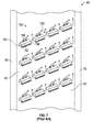
- the interaction of the vortices 142 can be eliminated by segmenting a skewed Chevron-type trip strip 150 into a series of sections 152, each including a leading edge 154 and a trailing edge 156, and each generating an air vortex 158, as shown in figure 7 , which provides multiple gaps 160 therebetween for cooling air to flow through.
- the thick boundary layer built-up by the vortices still reduces the tripping effect by the incoming cooling flow and thus reduces the heat transfer augmentation along the trip strip.
- the present invention proposes a new configuration for the trip strip 100 that eliminates the thick boundary layer caused by the build-up of the air vortices.
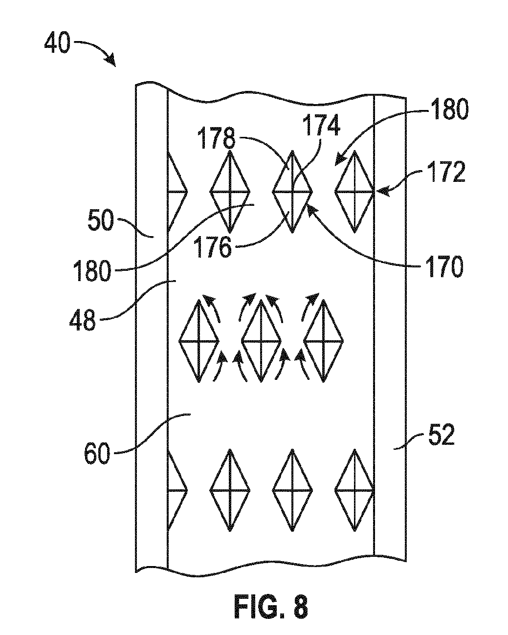
- Figure 8 is an illustration of a portion of the blade 40 showing a portion of the channel portion 62 similar to the illustrations shown in figures 4 , 6 and 7 , where the cooling flow is in an upward direction.
- the trip strip 100 is configured as diamond-shaped turbulators 170, where each turbulator 170 has a pointed peak 174, a leading edge 176 and a trailing edge 178.
- the diamond-shape of the turbulators 170 provides a front side and a back side of the turbulators 170 that are mirror images of each other.
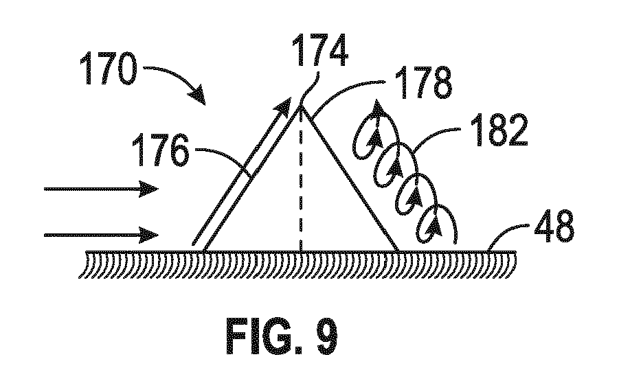
- Figure 9 shows a side view of one of the turbulators 170 and figure 10 shows a top view of two adjacent turbulators 170 both showing the airflow around the turbulators 170, where arrows depict the flow of air over and around the turbulators 170.
- the turbulators 170 are arranged or configured in rows 172, where the turbulators 170 are spaced apart to create gaps 180 therebetween.
- the rows 172 of the turbulators 170 are configured so a turbulator 170 in one of the rows 172 is positioned relative to the gap 180 between two adjacent turbulators 170 in an adjacent row 172, as shown.
- the turbulators 170 are constructed with an increase in height and width along the length of the turbulator 170 from the leading edge 176 of the turbulator 170 to the mid-point of the turbulator 170.
- the cooling flow is tripped by the front portion or leading edge 176 of the turbulator 170, which creates a "ski-jump" upward where the airflow spreads outward and rolls along the length of the turbulator 170.
- the tripped cooling flow will reattach to the channel wall, thus creating a very high heat transfer coefficient at the location of the re-attachment.
- a backward counter air vortex 182 is created on the back portion of the turbulator 170, which further enhances the turbulence level and prolongs the high heat transfer coefficient along the channel wall.
- the turbulators 170 eliminate the interaction of the air vortices between old vortices and newly formed vortices by the incoming cooling flow along the turbulator 170, thus creating a much more effective way of tripping the boundary layer and inducing a much higher heat transfer augmentation. Furthermore, for the end line arrangement of the turbulators 170, the converging and diverging gaps 180 between two discrete diamond-shaped turbulators 170 allows the cooling flow channel through the opening, generating a new boundary layer. With this newly formed boundary layer created by the diverging opening, a shearing-off effect of the air vortices generated by the turbulator 170 occurs.
Landscapes
- Engineering & Computer Science (AREA)
- Mechanical Engineering (AREA)
- General Engineering & Computer Science (AREA)
- Chemical & Material Sciences (AREA)
- Combustion & Propulsion (AREA)
- Physics & Mathematics (AREA)
- Fluid Mechanics (AREA)
- Turbine Rotor Nozzle Sealing (AREA)
Abstract
A turbulator having a diamond-shaped configuration where a front portion of the turbulator is a mirror image of a rear portion of the turbulator, and where the turbulator has application for cooling flow channels in a blade of a gas turbine engine. An array of the diamond-shaped turbulators is positioned in rows relative to the flow of the cooling air so that a turbulator in one of the rows is positioned relative to the gap between two turbulators in an adjacent row to break up the flow of air flowing between the turbulators.
Description
- This invention relates generally to a turbulator that provides a turbulent airflow within cooling channels in a blade of a gas turbine engine and, more particularly, to a turbulator that provides a turbulent airflow within cooling channels in a blade of a gas turbine engine, where the turbulator has a diamond-shaped configuration.
- The world's energy needs continue to rise which provides a demand for reliable, affordable, efficient and environmentally-compatible power generation. A gas turbine engine is one known machine that provides efficient power, and often has application for an electric generator in a power plant, or engines in an aircraft or a ship. A typically gas turbine engine includes a compressor section, a combustion section and a turbine section. The compressor section provides a compressed air flow to the combustion section where the air is mixed with a fuel, such as natural gas, and ignited to create a hot working gas. The working gas expands through the turbine section and is directed across rows of blades therein by associated vanes. As the working gas passes through the turbine section, it causes the blades to rotate, which in turn causes a shaft to rotate, thereby providing mechanical work.
- The temperature of the working gas is tightly controlled so that it does not exceed some predetermined temperature for a particular turbine engine design because to high of a temperature can damage various parts and components in the turbine section of the engine. However, it is desirable to allow the temperature of the working gas to be as high as possible because the higher the temperature of the working gas, the faster the flow of the gas, which results in a more efficient operation of the engine.
- In certain gas engine turbine designs, a portion of the compressed air flow is also used to provide cooling for certain components in the turbine section, typically the vanes, blades and ring segments. The more cooling and/or the more efficient cooling that can be provided to these components allows the components to be maintained at a lower temperature, and thus the higher the temperature of the working gas can be. For example, by reducing the temperature of the compressed gas, less compressed gas is required to maintain the part at the desired temperature, resulting in a higher working gas temperature and a greater power and efficiency from the engine. Further, by using less cooling air at one location in the turbine section, more cooling air can be used at another location in the turbine section. In one known turbine engine design, 80% of the compressed air flow is mixed with the fuel to provide the working gas and 20% of the compressed air flow is used to cool the turbine section parts. If less of that cooling air is used at one particular location as a result of the cooling air being lower in temperature, then more cooling air can be used at other areas in the turbine section for increased cooling.
- It is known in the art to provide a serpentine cooling airflow channel within the blades in the turbine section, where the air flows up one channel and down an adjacent channel in a back and forth motion before the cooling air exits the blade. In one known cooling air flow channel design, a series of specially configured turbulators or trip strips are positioned within the flow channels that cause the airflow over the trip strips to become turbulent. The disturbance in the air flow provided by the trip strip augments the local heat transfer coefficient of the air and thus enhances the cooling performance. Improvements can be made to the trip strips to further enhance the cooling performance.
- This disclosure describes a turbulator having a diamond-shaped configuration where a front portion of the turbulator is a mirror image of a rear portion of the turbulator, and where the turbulator has application for cooling flow channels in a blade of a gas turbine engine. An array of the diamond-shaped turbulators is positioned in rows relative to the flow of the cooling air so that a turbulator in one of the rows is positioned relative to the gap between two turbulators in an adjacent row to break up the flow of air flowing between the turbulators.
- Additional features of the present invention will become apparent from the following description and appended claims, taken in conjunction with the accompanying drawings.
-
-
Figure 1 is a cut-away, isometric view of a gas turbine engine; -
Figure 2 is a cross-sectional view of one blade separated from the row of the blades in the gas turbine engine and showing air cooling flow channels therein; -
Figure 3 is a cross-sectional view along line 3-3 of the blade shown infigure 2 ; -
Figure 4 is an illustration showing a number of known skewed trip strips within the flow channels in the blade shown infigures 2 and3 ; -
Figure 5 is a cross-sectional view of one of the trip strips shown infigure 4 ; -
Figure 6 is an illustration showing a series of known Chevron-type trip strips within the flow channels in the blade shown infigures 2 and3 ; -
Figure 7 is an illustration of known segmented and skewed trip strips within the flow channels in the blade shown infigures 2 and3 ; -
Figure 8 is an illustration showing a configuration of diamond-shaped turbulators within the flow channels in the blade shown infigures 2 and3 ; -
Figure 9 is a side view of one of the turbulators shown infigure 8 ; and -
Figure 10 is a top view of two adjacent turbulators shown infigure 8 . - The following discussion of the embodiments of the invention directed to a diamond-shaped turbulator for cooling flow channels within a gas turbine engine blade is merely exemplary in nature, and is in no way intended to limit the invention or its applications or uses.
-
Figure 1 is a cut-away, isometric view of agas turbine engine 10 including acompressor section 12, acombustion section 14 and aturbine section 16 all enclosed within an outer housing orcasing 30, where operation of theengine 10 causes a central shaft orrotor 18 to rotate, thus creating mechanical work. Theengine 10 is illustrated and described by way of a non-limiting example to give context to the invention discussed below. Those skilled in the art will appreciate that other gas turbine engine designs will also benefit from the invention. Rotation of therotor 18 draws air into thecompressor section 12 where it is directed byvanes 22 and compressed by rotating blades 20 to be delivered to thecombustion section 14 where the compressed air is mixed with a fuel, such as natural gas, and where the fuel/air mixture is ignited to create a hot working gas. More specifically, thecombustion section 14 includes a number of circumferentially disposedcombustors 26 each receiving the fuel in thecombustor 26 by an injector (not shown) and mixed with the compressed air to be ignited by anigniter 24 to create the working gas, which is directed by atransition 28 into theturbine section 16. The working gas is directed by circumferentially disposed stationary vanes (not shown) in theturbine section 16 to flow across circumferentially disposedrotatable turbine blades 34, which causes theturbine blades 34 to rotate, thus rotating therotor 18. Once the working gas passes through theturbine section 16 it is output from theengine 10 as an exhaust gas through anoutput nozzle 36. - Each group of the circumferentially disposed stationary vanes defines a row of the vanes and each group of the circumferentially disposed
blades 34 defines arow 38 of theblades 34. In this non-limiting embodiment, theturbine section 16 includes fourrows 38 of therotating blades 34 and four rows of the stationary vanes in an alternating sequence. In other gas turbine engine designs, theturbine section 16 may include more or less rows of theturbine blades 34. It is noted that the most forward row of theturbine blades 34, referred to as the row 1 blades, and the vanes, referred to as the row 1 vanes, receive the highest temperature of the working gas, where the temperature of the working gas decreases as it flows through theturbine section 16. -
Figure 2 is a cross-sectional view of an airfoil orblade 40 that is intended to represent a row 2 blade, but can be a general representation of any of theblades 34 in the rows in thegas turbine engine 10, where theblade 40 includes cooling fluid flow channels discussed in detail below.Figure 3 is a cross-sectional view of theblade 40 along line 3-3 infigure 2 . Theblade 40 includes anattachment portion 42 that is configured to allow theblade 40 to be securely mounted to therotor 18 in a manner well understood by those skilled in the art. Ablade platform 44 is provided at a distal end of theattachment portion 42 and defines the beginning of atapered airfoil portion 46 of theblade 40. - The
airfoil portion 46 includes anouter housing 48 and a number ofinternal ribs serpentine flow channel 60 including achannel portion 62 between theouter housing 48 and therib 50, achannel portion 64 between theribs channel portion 66 between theribs blade 40 through an input opening 70 in theattachment portion 42, enters thechannel portion 62 and flows towards anend portion 78 of thehousing 48, where some of the airflow exits theflow channel portion 62 throughorifices 80 in the end portion. The air then flows back down theblade 40 through thechannel portion 64 into achamber 72 in theattachment portion 42 that has an opening covered by acover plate 74. The air then flows back up theblade 40 through thechannel portion 66 and throughorifices 76 in theend portion 78 of theblade 40. Therib 54 includes an array oforifices 82 that allow some of the air to flow into animpingement channel 84 between theribs rib 56 includes an array oforifices 86 that allow the air to flow into achannel 88 between theribs rib 58 includes an array oforifices 92 that allow the air to flow into animpingement channel 94 between therib 58 and theouter housing 48. An array oforifices 96 in theouter housing 48 allows the air to flow out of theblade 40. As is apparent, theorifices ribs channels - It is known in the art to provide a configuration of turbulators or trip strips mounted to the inner walls of the
channel portions reference number 100 infigure 2 . It is noted that the discussion below will first describe known trip strips followed by a discussion of a new configuration of trip strips according to the invention, where thereference number 100 is intended to represent all infigure 2 . As is known in the art, a trip strip for this purpose is a metal strip formed to an inside surface of theouter housing 48 of theblade 40 in a transverse direction to the flow of the cooling air. In this design, the trip strips 100 are shown as skewed trip strips in that they are angled slightly relative to the direction of the flow of the cooling air. In an alternate embodiment, the trip strips 100 can be normal to the flow direction of the air. Skewed trip strips are sometimes employed over normal trip strips so as to allow the trip strip to be longer, which provides more turbulent airflow. -
Figure 4 is an illustration of a portion of theblade 40 showing part of thechannel portion 62. This illustration shows three known skewed trip strips 120 each including aleading edge 122 and a trailingedge 124.Figure 5 is a cross-sectional view of one of the trip strips 120. As the air flows across thetrip strip 120 in an upward direction infigure 4 , thetrip strip 120 trips the thermal boundary layer of the cooling air and causes it to generate anair vortex 126 along the length of thetrip strip 120 from theleading edge 122 to the trailingedge 124. The air flow over and around thetrip strip 120 is represented by the arrows infigure 5 . The configuration and orientation of the trip strips 120 causes the helical formation of theair vortex 126 to increase in size from theleading edge 122 to the trailingedge 124, i.e., increase in diameter. As the size of thevortex 126 increases the air becomes less turbulent, which reduces its effectiveness for cooling. Particularly, as thevortex 126 propagates along the full length of thetrip strip 120, the boundary layer becomes progressively more disturbed or thickened, and consequently the tripping effect of the boundary layer becomes progressively less effective. The net result of this boundary layer growth is a significantly reduced heat transfer augmentation. More specifically, as the airflow hits theleading edge 122 of thetrip strip 120 and thevortex 126 is created, by the time the boundary layer for that part of the airflow reaches the trailingedge 124 of thetrip strip 120, thevortex 126 is already present on thetrip strip 120, where the combination of the airflow in those directions increases the size of thevortex 126, which reduces the ability of thetrip strip 120 to trip the airflow. -
Figure 6 is an illustration of a portion of theblade 40 showing a portion of thechannel portion 62 similar to the illustration shown infigure 4 , where the cooling flow is in an upward direction. This illustration shows a series of known Chevron-type trip strips 130 each including opposing and skewedtrip strip sections gap 136 therebetween that are oriented in opposite directions, as shown, where each of thetrip strip sections leading edge 138 and a trailingedge 140. As above, eachtrip strip section air vortex 142 that travels from theleading edge 138 to the trailingedge 140. Airflow between thesections gap 136 interacts with thevortices 142, which creates two thick boundary layers at the junction of the trailingedges 140 of the twotrip strip sections - The interaction of the
vortices 142 can be eliminated by segmenting a skewed Chevron-type trip strip 150 into a series ofsections 152, each including aleading edge 154 and a trailingedge 156, and each generating anair vortex 158, as shown infigure 7 , which providesmultiple gaps 160 therebetween for cooling air to flow through. Regardless of either of these Chevron configurations, the thick boundary layer built-up by the vortices still reduces the tripping effect by the incoming cooling flow and thus reduces the heat transfer augmentation along the trip strip. - The present invention proposes a new configuration for the
trip strip 100 that eliminates the thick boundary layer caused by the build-up of the air vortices.Figure 8 is an illustration of a portion of theblade 40 showing a portion of thechannel portion 62 similar to the illustrations shown infigures 4 ,6 and7 , where the cooling flow is in an upward direction. In this new design, thetrip strip 100 is configured as diamond-shapedturbulators 170, where each turbulator 170 has a pointedpeak 174, aleading edge 176 and a trailingedge 178. The diamond-shape of theturbulators 170 provides a front side and a back side of theturbulators 170 that are mirror images of each other. -
Figure 9 shows a side view of one of theturbulators 170 andfigure 10 shows a top view of twoadjacent turbulators 170 both showing the airflow around theturbulators 170, where arrows depict the flow of air over and around theturbulators 170. Theturbulators 170 are arranged or configured inrows 172, where theturbulators 170 are spaced apart to creategaps 180 therebetween. Therows 172 of theturbulators 170 are configured so a turbulator 170 in one of therows 172 is positioned relative to thegap 180 between twoadjacent turbulators 170 in anadjacent row 172, as shown. Therefore, airflow between two of theturbulators 170 in onerow 172 interacts with aturbulator 170 in the next row downstream therefrom. Theturbulators 170 are constructed with an increase in height and width along the length of the turbulator 170 from theleading edge 176 of theturbulator 170 to the mid-point of theturbulator 170. - In operation, the cooling flow is tripped by the front portion or
leading edge 176 of theturbulator 170, which creates a "ski-jump" upward where the airflow spreads outward and rolls along the length of theturbulator 170. As the newly formed upper flow over theturbulator 170 continues, the tripped cooling flow will reattach to the channel wall, thus creating a very high heat transfer coefficient at the location of the re-attachment. A backwardcounter air vortex 182 is created on the back portion of theturbulator 170, which further enhances the turbulence level and prolongs the high heat transfer coefficient along the channel wall. Theturbulators 170 eliminate the interaction of the air vortices between old vortices and newly formed vortices by the incoming cooling flow along theturbulator 170, thus creating a much more effective way of tripping the boundary layer and inducing a much higher heat transfer augmentation. Furthermore, for the end line arrangement of theturbulators 170, the converging and diverginggaps 180 between two discrete diamond-shapedturbulators 170 allows the cooling flow channel through the opening, generating a new boundary layer. With this newly formed boundary layer created by the diverging opening, a shearing-off effect of the air vortices generated by theturbulator 170 occurs. - The foregoing discussion discloses and describes merely exemplary embodiments of the present invention. One skilled in the art will readily recognize from such discussion, and from the accompanying drawings and claims, that various changes, modifications and variations can be made therein without departing from the scope of the invention as defined in the following claims.
Claims (18)
- A blade for a gas turbine engine, said blade comprising:an outer housing wall defining an enclosure;a plurality of ribs extending at least a portion of a length of the blade within the enclosure and defining at least one flow channel that allows a cooling airflow to flow from a proximal end to a distal end of the enclosure; anda plurality of spaced apart diamond-shaped turbulators each having a peak and being formed to an inside surface of the outer housing wall and extending into the flow channel, said plurality of diamond-shape turbulators being formed in an array of rows where a turbulator in one row is positioned relative to a gap between adjacent turbulators in an adjacent row.
- The blade according to claim 1 wherein a front portion of each turbulator is a mirror image of a back portion of each turbulator.
- The blade according to claim 1 wherein each turbulator includes a pointed peak.
- The blade according to claim 1 wherein the blade is part of a second row of blades in a turbine section of the gas turbine engine.
- The blade according to claim 1 wherein each turbulator is formed from a metal.
- The blade according to claim 1 wherein the at least one flow channel is a serpentine flow channel.
- A diamond-shaped turbulator for creating a turbulated airflow in a cooling flow channel, said turbulator having a diamond-shape defining a pointed peak where a front portion of the turbulator and a back portion of the turbulator are mirror images of each other.
- The turbulator according to claim 7 wherein the turbulator is part of an array of turbulators arranged in rows in the cooling channel where a turbulator in one row is positioned relative to a gap between adjacent turbulators in an adjacent row.
- The turbulator according to claim 7 wherein the cooling fluid flow channel is provided within a blade for a gas turbine engine.
- The turbulator according to claim 9 wherein the blade is part of a second row of blades in a turbine section of the gas turbine engine.
- The turbulator according to claim 9 wherein the cooling fluid flow channel is a serpentine flow channel.
- The turbulator according to claim 7 wherein the turbulator is formed from a metal.
- A gas turbine engine comprising:an outer housing;a compressor section being operable to produce a compressed air flow;a combustion section in fluid communication with the compressor section that receives a combustion portion of the compressed air flow, said combustion section mixing the combustion portion of the compressed air flow with a fuel and combusting the mixture to produce a hot working gas; anda turbine section in fluid communication with the combustion section, said turbine section receiving the hot working gas, said turbine section including a plurality of rows of vanes and a plurality of rows of blades, wherein at least some of the blades include an outer housing wall defining an enclosure, a plurality of ribs extending at least a portion of a length of the blade within the enclosure and defining at least one flow channel that allows a cooling airflow to flow from a proximal end to a distal end of the enclosure, and a plurality of spaced apart diamond-shaped turbulators each having a peak and being formed to an inside surface of the outer housing wall and extending into the flow channel, said plurality of diamond-shape turbulators being formed in an array of rows where a turbulator in one row is positioned relative to a gap between adjacent turbulators in an adjacent row.
- The gas turbine engine according to claim 13 wherein a front portion of each turbulator is a mirror image of a back portion of each turbulator.
- The gas turbine engine according to claim 13 wherein each turbulator includes a pointed peak.
- The gas turbine engine according to claim 13 wherein the at least some of the blades are part of a second row of blades in the turbine section.
- The gas turbine engine according to claim 13 wherein each turbulator is formed from a metal.
- The gas turbine engine according to claim 13 wherein the at least one flow channel is a serpentine flow channel.
Applications Claiming Priority (1)
| Application Number | Priority Date | Filing Date | Title |
|---|---|---|---|
| US14/093,564 US20150152738A1 (en) | 2013-12-02 | 2013-12-02 | Turbine airfoil cooling passage with diamond turbulator |
Publications (1)
| Publication Number | Publication Date |
|---|---|
| EP2878768A1 true EP2878768A1 (en) | 2015-06-03 |
Family
ID=52013831
Family Applications (1)
| Application Number | Title | Priority Date | Filing Date |
|---|---|---|---|
| EP14194492.6A Withdrawn EP2878768A1 (en) | 2013-12-02 | 2014-11-24 | Blade with peaked diamond-shaped turbulators, corresponding turbulator and gas turbine engine |
Country Status (6)
| Country | Link |
|---|---|
| US (1) | US20150152738A1 (en) |
| EP (1) | EP2878768A1 (en) |
| JP (1) | JP2015105657A (en) |
| KR (1) | KR20150063950A (en) |
| CN (1) | CN104675444A (en) |
| CA (1) | CA2872565A1 (en) |
Cited By (1)
| Publication number | Priority date | Publication date | Assignee | Title |
|---|---|---|---|---|
| EP3181821A1 (en) * | 2015-12-15 | 2017-06-21 | United Technologies Corporation | Turbulators for improved cooling of gas turbine engine components |
Families Citing this family (11)
| Publication number | Priority date | Publication date | Assignee | Title |
|---|---|---|---|---|
| US9835087B2 (en) * | 2014-09-03 | 2017-12-05 | General Electric Company | Turbine bucket |
| US9926788B2 (en) * | 2015-12-21 | 2018-03-27 | General Electric Company | Cooling circuit for a multi-wall blade |
| US10092878B2 (en) * | 2016-03-03 | 2018-10-09 | General Electric Company | System and method for mixing tempering air with flue gas for hot SCR catalyst |
| KR101797370B1 (en) * | 2016-07-04 | 2017-12-12 | 두산중공업 주식회사 | Gas Turbine Blade |
| WO2018136042A1 (en) * | 2017-01-18 | 2018-07-26 | Siemens Aktiengesellschaft | Turbine element |
| US10697301B2 (en) * | 2017-04-07 | 2020-06-30 | General Electric Company | Turbine engine airfoil having a cooling circuit |
| KR101873156B1 (en) * | 2017-04-12 | 2018-06-29 | 두산중공업 주식회사 | Turbine vane and gas turbine having the same |
| KR102215407B1 (en) | 2018-10-29 | 2021-02-10 | 건국대학교 산학협력단 | Vegetable meat prepared with vegetable fat and method for preparing the same |
| CN113153590A (en) * | 2021-03-29 | 2021-07-23 | 清华大学 | Turbulence generator |
| JP7067756B2 (en) | 2021-12-04 | 2022-05-16 | 直樹 豊川 | Turbine blade |
| CN115013075B (en) * | 2022-08-10 | 2022-12-06 | 中国航发四川燃气涡轮研究院 | Anti-slip pattern-shaped turbulence rib and turbine blade |
Citations (3)
| Publication number | Priority date | Publication date | Assignee | Title |
|---|---|---|---|---|
| WO2004035992A1 (en) * | 2002-10-18 | 2004-04-29 | Alstom Technology Ltd. | Component capable of being cooled |
| GB2399405A (en) * | 2003-03-10 | 2004-09-15 | Alstom | Enhancement of heat transfer |
| US20080063524A1 (en) * | 2006-09-13 | 2008-03-13 | Rolls-Royce Plc | Cooling arrangement for a component of a gas turbine engine |
Family Cites Families (2)
| Publication number | Priority date | Publication date | Assignee | Title |
|---|---|---|---|---|
| EP2584145A1 (en) * | 2011-10-20 | 2013-04-24 | Siemens Aktiengesellschaft | A cooled turbine guide vane or blade for a turbomachine |
| US8870525B2 (en) * | 2011-11-04 | 2014-10-28 | General Electric Company | Bucket assembly for turbine system |
-
2013
- 2013-12-02 US US14/093,564 patent/US20150152738A1/en not_active Abandoned
-
2014
- 2014-11-24 EP EP14194492.6A patent/EP2878768A1/en not_active Withdrawn
- 2014-11-28 CA CA2872565A patent/CA2872565A1/en not_active Abandoned
- 2014-12-02 JP JP2014243850A patent/JP2015105657A/en active Pending
- 2014-12-02 CN CN201410715938.1A patent/CN104675444A/en active Pending
- 2014-12-02 KR KR1020140170763A patent/KR20150063950A/en not_active Withdrawn
Patent Citations (3)
| Publication number | Priority date | Publication date | Assignee | Title |
|---|---|---|---|---|
| WO2004035992A1 (en) * | 2002-10-18 | 2004-04-29 | Alstom Technology Ltd. | Component capable of being cooled |
| GB2399405A (en) * | 2003-03-10 | 2004-09-15 | Alstom | Enhancement of heat transfer |
| US20080063524A1 (en) * | 2006-09-13 | 2008-03-13 | Rolls-Royce Plc | Cooling arrangement for a component of a gas turbine engine |
Cited By (1)
| Publication number | Priority date | Publication date | Assignee | Title |
|---|---|---|---|---|
| EP3181821A1 (en) * | 2015-12-15 | 2017-06-21 | United Technologies Corporation | Turbulators for improved cooling of gas turbine engine components |
Also Published As
| Publication number | Publication date |
|---|---|
| CA2872565A1 (en) | 2015-06-02 |
| KR20150063950A (en) | 2015-06-10 |
| CN104675444A (en) | 2015-06-03 |
| JP2015105657A (en) | 2015-06-08 |
| US20150152738A1 (en) | 2015-06-04 |
Similar Documents
| Publication | Publication Date | Title |
|---|---|---|
| US20150152738A1 (en) | Turbine airfoil cooling passage with diamond turbulator | |
| EP2918781A1 (en) | Turbine blade with near wall microcircuit edge cooling | |
| EP2578803B1 (en) | Methods and systems for use in regulating a temperature of components | |
| EP2562479B1 (en) | Wall elements for gas turbine engines | |
| JP6283462B2 (en) | Turbine airfoil | |
| US9133716B2 (en) | Turbine endwall with micro-circuit cooling | |
| US5704763A (en) | Shear jet cooling passages for internally cooled machine elements | |
| US8920122B2 (en) | Turbine airfoil with an internal cooling system having vortex forming turbulators | |
| US8985949B2 (en) | Cooling system including wavy cooling chamber in a trailing edge portion of an airfoil assembly | |
| US7637720B1 (en) | Turbulator for a turbine airfoil cooling passage | |
| US8167560B2 (en) | Turbine airfoil with an internal cooling system having enhanced vortex forming turbulators | |
| US7347671B2 (en) | Turbine blade turbulator cooling design | |
| US20050232771A1 (en) | Turbine rotor blades | |
| EP2131109A2 (en) | Counter-vortex, paired film cooling hole design | |
| US20130315710A1 (en) | Gas turbine engine components with cooling hole trenches | |
| EP1645722A2 (en) | Turbine airfoil with stepped coolant outlet slots | |
| US10247099B2 (en) | Pedestals with heat transfer augmenter | |
| EP3271554A1 (en) | Internal cooling system with converging-diverging exit slots in trailing edge cooling channel for an airfoil in a turbine engine | |
| US20140338866A1 (en) | Cooling passage including turbulator system in a turbine engine component | |
| US20170159454A1 (en) | Gas turbine engine component with a baffle insert | |
| US20170159455A1 (en) | Baffle insert for a gas turbine engine component | |
| US20170138204A1 (en) | Cooling structure and gas turbine | |
| EP3181821A1 (en) | Turbulators for improved cooling of gas turbine engine components | |
| US9273558B2 (en) | Saw teeth turbulator for turbine airfoil cooling passage | |
| EP3933173A1 (en) | Inserts for airfoils of gas turbine engines |
Legal Events
| Date | Code | Title | Description |
|---|---|---|---|
| PUAI | Public reference made under article 153(3) epc to a published international application that has entered the european phase |
Free format text: ORIGINAL CODE: 0009012 |
|
| 17P | Request for examination filed |
Effective date: 20141124 |
|
| AK | Designated contracting states |
Kind code of ref document: A1 Designated state(s): AL AT BE BG CH CY CZ DE DK EE ES FI FR GB GR HR HU IE IS IT LI LT LU LV MC MK MT NL NO PL PT RO RS SE SI SK SM TR |
|
| AX | Request for extension of the european patent |
Extension state: BA ME |
|
| STAA | Information on the status of an ep patent application or granted ep patent |
Free format text: STATUS: THE APPLICATION IS DEEMED TO BE WITHDRAWN |
|
| 18D | Application deemed to be withdrawn |
Effective date: 20151204 |