EP2878514A2 - Method and apparatus for detecting motor error of motor driven power steering - Google Patents
Method and apparatus for detecting motor error of motor driven power steering Download PDFInfo
- Publication number
- EP2878514A2 EP2878514A2 EP14173707.2A EP14173707A EP2878514A2 EP 2878514 A2 EP2878514 A2 EP 2878514A2 EP 14173707 A EP14173707 A EP 14173707A EP 2878514 A2 EP2878514 A2 EP 2878514A2
- Authority
- EP
- European Patent Office
- Prior art keywords
- motor
- phase
- current
- command current
- preset
- Prior art date
- Legal status (The legal status is an assumption and is not a legal conclusion. Google has not performed a legal analysis and makes no representation as to the accuracy of the status listed.)
- Granted
Links
- 238000000034 method Methods 0.000 title claims abstract description 28
- 230000009466 transformation Effects 0.000 claims description 10
- 230000007423 decrease Effects 0.000 claims description 6
- 238000001514 detection method Methods 0.000 description 5
- 238000010586 diagram Methods 0.000 description 2
- 102100028950 Dual specificity protein phosphatase 13 isoform A Human genes 0.000 description 1
- 101000838551 Homo sapiens Dual specificity protein phosphatase 13 isoform A Proteins 0.000 description 1
- 238000007792 addition Methods 0.000 description 1
- 238000012986 modification Methods 0.000 description 1
- 230000004048 modification Effects 0.000 description 1
- 238000006467 substitution reaction Methods 0.000 description 1
Images


Classifications
-
- B—PERFORMING OPERATIONS; TRANSPORTING
- B62—LAND VEHICLES FOR TRAVELLING OTHERWISE THAN ON RAILS
- B62D—MOTOR VEHICLES; TRAILERS
- B62D5/00—Power-assisted or power-driven steering
- B62D5/04—Power-assisted or power-driven steering electrical, e.g. using an electric servo-motor connected to, or forming part of, the steering gear
- B62D5/0457—Power-assisted or power-driven steering electrical, e.g. using an electric servo-motor connected to, or forming part of, the steering gear characterised by control features of the drive means as such
- B62D5/0481—Power-assisted or power-driven steering electrical, e.g. using an electric servo-motor connected to, or forming part of, the steering gear characterised by control features of the drive means as such monitoring the steering system, e.g. failures
- B62D5/0487—Power-assisted or power-driven steering electrical, e.g. using an electric servo-motor connected to, or forming part of, the steering gear characterised by control features of the drive means as such monitoring the steering system, e.g. failures detecting motor faults
-
- B—PERFORMING OPERATIONS; TRANSPORTING
- B62—LAND VEHICLES FOR TRAVELLING OTHERWISE THAN ON RAILS
- B62D—MOTOR VEHICLES; TRAILERS
- B62D5/00—Power-assisted or power-driven steering
- B62D5/04—Power-assisted or power-driven steering electrical, e.g. using an electric servo-motor connected to, or forming part of, the steering gear
- B62D5/0457—Power-assisted or power-driven steering electrical, e.g. using an electric servo-motor connected to, or forming part of, the steering gear characterised by control features of the drive means as such
- B62D5/046—Controlling the motor
-
- G—PHYSICS
- G01—MEASURING; TESTING
- G01R—MEASURING ELECTRIC VARIABLES; MEASURING MAGNETIC VARIABLES
- G01R19/00—Arrangements for measuring currents or voltages or for indicating presence or sign thereof
- G01R19/0092—Arrangements for measuring currents or voltages or for indicating presence or sign thereof measuring current only
-
- G—PHYSICS
- G01—MEASURING; TESTING
- G01R—MEASURING ELECTRIC VARIABLES; MEASURING MAGNETIC VARIABLES
- G01R31/00—Arrangements for testing electric properties; Arrangements for locating electric faults; Arrangements for electrical testing characterised by what is being tested not provided for elsewhere
- G01R31/34—Testing dynamo-electric machines
Definitions
- the present invention relates to a method and apparatus for detecting a motor error of a motor driven power steering (MDPS), and more particularly, to a method and apparatus for detecting a motor error of MDPS, which quickly detects disconnection of a line connected to each phase of a motor of the MDPS, thereby securing the safety of a driver.
- MDPS motor driven power steering
- each upper logic calculates a proper command to generate steering torque.
- the disconnection was detected through the Q-axis command current of the motor.
- the detection was impossible.
- the steering wheel speed and current variation ratio are reflected to detect disconnection, the detection was impossible when the steering wheel is slowly operated, for example, when a vehicle is driven at low speed or stopped for a while.
- the method has limitation in detecting disconnection.
- Embodiments of the present invention are directed to a method and apparatus for detecting a motor error of MDPS, which quickly detects disconnection of a line connected to each phase of a motor of the MDPS, thereby securing the safety of a driver.
- a method for detecting a motor error of MDPS may include: calculating, by a control unit, a Q-axis command current of a motor through a Q-axis command current calculation unit, according to requested torque; calculating a command current of each phase of the motor from the calculated Q-axis command current of the motor; controlling the motor according to the Q-axis command current of the motor, and sensing a measured current of each phase of the motor through each current sensor; determining whether each phase of the motor is disconnected, through the command current and the measured current of each phase of the motor; and outputting the determination result to an output unit.
- the calculating of the command current of each phase of the motor may include calculating the command current of each phase of the motor through rotation coordinate transformation with respect to a Q-axis of the motor.
- the determining of whether each phase of the motor is disconnected may include: increasing an error count, when the measured current is smaller than a preset measured current and the command current is larger than a preset command current; and determining that disconnection occurred, when the increased error count is larger than a preset count.
- the control unit may decrease the error count.
- an apparatus for detecting a motor error of MDPS may include: a Q-axis command current calculation unit configured to calculate a Q-axis command current of a motor according to requested torque; a motor driving unit configured to calculate a command current of each phase of the motor from the calculated Q-axis command current of the motor, and control the motor according to the Q-axis command current of the motor; a current sensor configured to sense a measured current of each phase of the motor; a control unit configured to determine whether each phase of the motor is disconnected, through the command current and the measured current of each phase of the motor; and an output unit configured to output the determination result of the control unit.
- the motor driving unit may calculate the command current of each phase of the motor through rotation coordinate transformation with respect to the Q-axis of the motor.
- the current sensor may sense the measured current of each phase of the motor, when the motor is controlled.
- the control unit may increase an error count, and when the error count is larger than a preset count, the control unit may determine that disconnection occurred.
- the control unit may decrease the error count.
- the method and apparatus for detecting a motor error of MDPS may quickly detect disconnection of a line connected to each phase of the motor of MDPS, thereby securing the safety of a driver.
- the method and apparatus may detect disconnection of each phase of the motor through the measured current and the command current of the phase of the motor.
- the method and apparatus may detect an error at high speed, and detect motor phase disconnection regardless of driving conditions, thereby improving the error detection ability.
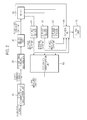
- FIG. 2 is a block configuration diagram illustrating an apparatus for detecting a motor error of MDPS in accordance with an embodiment of the present invention.
- the apparatus for detecting a motor error of MDPS in accordance with the embodiment of the present invention may include a Q-axis command current calculation unit 10, a proportional-integral control unit 20, a motor driving unit 30, a motor 40, an A-phase current sensor 51, a B-phase current sensor 52, a C-phase current sensor 53, a control unit 60, an output unit 70, and a coordinate transformation unit 80.
- the Q-axis command current calculation unit 10 may calculate a Q-axis command current of the motor 40 according to requested torque.
- the proportional-integral control unit 20 may proportionally control the Q-axis command current of the motor 40, calculated through the Q-axis command current calculation unit 10, and integrate an error signal to output a motor control signal.
- the motor driving unit 30 may calculate the PWM duty of the motor control signal outputted from the proportional-integral control unit 20, and calculate a command current of each phase of the motor 40.
- the motor 40 may be driven according to the Q-axis command current.
- the current sensors 51, 52, and 53 can be provided for the respective phases of the motor 40.
- a three-phase motor is used as the motor 40.
- an A-phase measured current, a B-phase measured current, and a C-phase measured current may be sensed through the A-phase current sensor 51, the B-phase current sensor 52, and the C-phase current sensor 53, respectively.
- the control unit 60 may compare the command currents of the phases of the motor 40, calculated through the motor driving unit 30, to the A-phase, B-phase, and C-phase measured currents, respectively, and determine whether disconnection occurred in the respective phases of the motor 40.
- the A phase of the motor 40 may be taken as an example for description.
- the control unit 60 may determine whether the A-phase measured current of the motor 40 is equal to or more than a preset measured current. When the A-phase measured current of the motor 40 is less than the preset measured current, the control unit 60 may determine whether the A-phase command current of the motor 40 has a larger value than a preset command current. When the A-phase command current of the motor 40 has a larger value than the preset command current, the control unit 60 may increase an error count.
- control unit 60 may increase the error count, and when any one of the two conditions is not satisfied, the control unit 60 may decrease the error count.
- control unit 60 may determine that the A-phase of the motor 40 is disconnected.
- the control unit 60 may determine disconnection of the B-phase and C-phase of the motor 40 in the same manner.
- the control unit 60 may determine whether the measured current is smaller than the preset measured current.
- the preset measured current may be set to a near-zero value.
- the control unit 60 may determine that disconnection occurred.
- D-axis and Q-axis command currents of the motor 40 may be calculated. These values may be used to calculate the command currents of the respective phases (A-phase, B-phase, and C-phase) of the motor 40 through D-Q rotation coordinate transformation.
- the control unit 60 may determine that the phase was disconnected.
- the output unit 70 may output the phase of the motor 40, which was determined to be disconnected.
- the coordinate transformation unit 80 may calculate a Q-axis measured current of the motor 40 through the rotation coordinate transformation for the D-axis and Q-axis of the motor 40, using the A-phase measured current, the B-phase measured current, and the C-phase measured current.
- the calculated Q-axis measured current of the motor 40 may be reflected when the Q-axis command current calculation unit 10 calculates the Q-axis command current of the motor 40.
- FIGS. 3A to 3D illustrate the process of detecting disconnection of motor phase in the apparatus for detecting a motor error of MDPS in accordance with the embodiment of the present invention.
- FIG. 3A is a graph illustrating requested torque.
- the Q-axis command current calculation unit 10 may calculate a Q-axis command current of the motor 40 by multiplying the Q-axis current of the motor 40 by a constant, and the Q-axis command current is illustrated in FIG. 3B .
- the motor driving unit 30 may calculate a three-phase command current to drive the motor 40 as illustrated in FIG. 3C .
- graphs A, B, and C of FIG. 3C illustrate command currents of the A-phase, the B-phase, and the C-phase, respectively.
- FIG. 3D illustrates an A-phase measured current, a B-phase measured current, and a C-phase measured current which are sensed through the A-phase current sensor 51, the B-phase current sensor 52, and the C-phase current sensor 53, respectively.
- FIG. 3D only the graphs B and C are detected, which indicates that the line of the A-phase of the motor 40 was disconnected.
- the apparatus for detecting a motor error of MDPS in accordance with the embodiment of the present invention may quickly detect disconnection of a line connected to each phase of the motor of MDPS, thereby securing the safety of a driver.
- the apparatus may detect disconnection of each phase of the motor through the measured current and the command current of the phase of the motor.
- the apparatus may detect an error at high speed, and detect motor phase disconnection regardless of driving conditions, thereby improving the error detection ability.
- FIG. 4 is a flowchart illustrating a method for detecting a motor error of MDPS in accordance with an embodiment of the present invention. Referring to FIG. 4 , the method for detecting a motor error of MDSP in accordance with the embodiment of the present invention will be described in detail.
- control unit 60 may calculate a Q-axis command current of the motor 40 according to requested torque, at step S100.
- the Q-axis command current calculation unit 10 may calculate the Q-axis command current of the motor 40 according to the requested torque.
- the control unit 60 may calculate a command current of each phase of the motor 40 from the Q-axis command current of the motor 40, calculated at step S100, at step S200.
- the command current of each phase of the motor 40 may be calculated through rotation coordinate transformation between the Q-axis and the D-axis of the motor 40.
- the proportional-integral control unit 20 may proportionally control the Q-axis command current of the motor 40, calculated through the Q-axis command current calculation unit 10, and integrate an error signal to output a motor control signal.
- the motor driving unit 30 may calculate the PWM duty of the motor control signal outputted from the proportional-integral control unit 20 so as to calculate the command current of each phase of the motor 40.
- control unit 60 may control the motor 40 according to the Q-axis command current of the motor 40, at step S300.
- measured currents of the respective phases of the motor 40 may be sensed through the current sensors 51, 52, and 53 of the respective phases of the motor 40, at step S400.
- a three-phase motor is used as the motor 40.
- an A-phase measured current, a B-phase measured current, and a C-phase measured current may be sensed through the A-phase current sensor 51, the B-phase current sensor 52, and the C-phase current sensor 53, respectively.
- the control unit 60 may compare the command currents of the respective phases of the motor 40, calculated through the motor driving unit 30, to the measured currents of the respective phases, determine whether the respective phases of the motor 40 are disconnected, and output the determination results to the output unit 70, at step S500.
- FIG. 5 is a flowchart illustrating a process of detecting disconnection of the A phase of the motor in the method for detecting a motor error of MDPS in accordance with the embodiment of the present invention.
- the A phase of the motor 40 will be described.
- the measured current of the A phase of the motor 40 may be sensed at step S10.
- the measured current of the A phase of the motor 40, sensed at step S10, may be compared to a preset measured current at step S20.
- a command current of the A phase of the motor 40 may be compared to a preset command current at step S30.
- control unit 60 may increase an error count at step S40.
- control unit 60 may increase the error count, and when any one of steps S20 and S30 is not satisfied, the control unit 60 may decrease the error count, at step S41.
- the control unit 60 may determine whether the increased error count is larger than a preset count, at step S50.
- control unit 60 may output disconnection of the A phase of the motor 40 through the output unit 70 at step S60.
- the disconnection of the B phase and the C phase of the motor 40 may be determined in the same manner.
- control unit 60 may determine whether the measured current is smaller than the preset measured current.
- the preset measured current may be set to a near-zero value.
- the control unit 60 may determine that disconnection occurred.
- D-axis and Q-axis command currents of the motor 40 may be calculated. These values may be used to calculate the command currents of the respective phases (A-phase, B-phase, and C-phase) of the motor 40 through D-Q rotation coordinate transformation.
- the control unit 60 may determine that the phase was disconnected.
- the method for detecting a motor error of MDPS in accordance with the embodiment of the present invention may quickly detect disconnection of a line connected to each phase of the motor of MDPS, thereby securing the safety of a driver.
- the method may detect disconnection of each phase of the motor through the measured current and the command current of the phase of the motor.
- the method may detect an error at high speed, and detect motor phase disconnection regardless of driving conditions, thereby improving the error detection ability.
Landscapes
- Engineering & Computer Science (AREA)
- Chemical & Material Sciences (AREA)
- Combustion & Propulsion (AREA)
- Transportation (AREA)
- Mechanical Engineering (AREA)
- Physics & Mathematics (AREA)
- General Physics & Mathematics (AREA)
- Power Steering Mechanism (AREA)
- Steering Control In Accordance With Driving Conditions (AREA)
- Control Of Ac Motors In General (AREA)
Abstract
Description
- The present application claims priority to Korean application number
10-2013-0147161, filed on November 29, 2013 - The present invention relates to a method and apparatus for detecting a motor error of a motor driven power steering (MDPS), and more particularly, to a method and apparatus for detecting a motor error of MDPS, which quickly detects disconnection of a line connected to each phase of a motor of the MDPS, thereby securing the safety of a driver.
- Since MDPS generates an assist thrust through a motor, each upper logic calculates a proper command to generate steering torque.
- That is, as illustrated in
FIG. 1 , when MDPS operating logic detects a motion of a steering wheel by a driver, a command calculated through steering performance logic is transmitted to torque limit logic to limit excessive torque, and steering torque is generated by a command calculated through motor control logic. - At this time, when a line connected to a phase of the motor is disconnected in the motor control logic, a current cannot flow through the corresponding phase. Thus, the MDPS does not normally operate, but fail-safe logic is driven.
- Conventionally, in order to detect disconnection of each phase line of the motor, D-axis and Q-axis current errors of the motor have been used, steering wheel rotation speed and current variation ratio have been reflected, or a current of each phase has been sensed and checked.
- In such a method, however, the disconnection was detected through the Q-axis command current of the motor. Thus, during high-speed traveling, the detection was impossible. Furthermore, since the steering wheel speed and current variation ratio are reflected to detect disconnection, the detection was impossible when the steering wheel is slowly operated, for example, when a vehicle is driven at low speed or stopped for a while. Thus, the method has limitation in detecting disconnection.
- Furthermore, since the current of each phase of the motor has an 0 A value at a specific motor position, it is difficult to distinguish a normal situation from disconnection only through the Q-axis command current of the motor and the measured current of each phase of the motor.
- The related art of the present invention is disclosed in Korean Patent Laid-open Publication No.
10-2012-0033171 published on April 6, 2012 - Embodiments of the present invention are directed to a method and apparatus for detecting a motor error of MDPS, which quickly detects disconnection of a line connected to each phase of a motor of the MDPS, thereby securing the safety of a driver.
- In one embodiment, a method for detecting a motor error of MDPS may include: calculating, by a control unit, a Q-axis command current of a motor through a Q-axis command current calculation unit, according to requested torque; calculating a command current of each phase of the motor from the calculated Q-axis command current of the motor; controlling the motor according to the Q-axis command current of the motor, and sensing a measured current of each phase of the motor through each current sensor; determining whether each phase of the motor is disconnected, through the command current and the measured current of each phase of the motor; and outputting the determination result to an output unit.
- The calculating of the command current of each phase of the motor may include calculating the command current of each phase of the motor through rotation coordinate transformation with respect to a Q-axis of the motor.
- The determining of whether each phase of the motor is disconnected may include: increasing an error count, when the measured current is smaller than a preset measured current and the command current is larger than a preset command current; and determining that disconnection occurred, when the increased error count is larger than a preset count.
- When the measured current is equal to or more than the preset measured current or the command current is equal to or less than the preset command current, the control unit may decrease the error count.
- In another embodiment, an apparatus for detecting a motor error of MDPS may include: a Q-axis command current calculation unit configured to calculate a Q-axis command current of a motor according to requested torque; a motor driving unit configured to calculate a command current of each phase of the motor from the calculated Q-axis command current of the motor, and control the motor according to the Q-axis command current of the motor; a current sensor configured to sense a measured current of each phase of the motor; a control unit configured to determine whether each phase of the motor is disconnected, through the command current and the measured current of each phase of the motor; and an output unit configured to output the determination result of the control unit.
- The motor driving unit may calculate the command current of each phase of the motor through rotation coordinate transformation with respect to the Q-axis of the motor.
- The current sensor may sense the measured current of each phase of the motor, when the motor is controlled.
- When the measured current is smaller than a preset measured current and the command current is larger than a preset command current, the control unit may increase an error count, and when the error count is larger than a preset count, the control unit may determine that disconnection occurred.
- When the measured current is equal to or more than the preset measured current or the command current is equal to or less than the preset command current, the control unit may decrease the error count.
- In accordance with the embodiments of the present invention, the method and apparatus for detecting a motor error of MDPS may quickly detect disconnection of a line connected to each phase of the motor of MDPS, thereby securing the safety of a driver.
- Furthermore, the method and apparatus may detect disconnection of each phase of the motor through the measured current and the command current of the phase of the motor. Thus, since a combination of driving conditions such as vehicle speed and steering wheel rotation speed is not needed, the method and apparatus may detect an error at high speed, and detect motor phase disconnection regardless of driving conditions, thereby improving the error detection ability.
-
-
FIG. 1 briefly illustrates MDPS operating logic. -
FIG. 2 is a block configuration diagram illustrating an apparatus for detecting a motor error of MDPS in accordance with an embodiment of the present invention. -
FIGS. 3A to 3D illustrate a process of detecting disconnection of motor phase in the apparatus for detecting a motor error of MDPS in accordance with the embodiment of the present invention. -
FIG. 4 is a flowchart illustrating a method for detecting a motor error of MDPS in accordance with an embodiment of the present invention. -
FIG. 5 is a flowchart illustrating a process of detecting disconnection of A phase of a motor in the method for detecting a motor error of MDPS in accordance with the embodiment of the present invention. - Embodiments of the invention will hereinafter be described in detail with reference to the accompanying drawings. It should be noted that the drawings are not to precise scale and may be exaggerated in thickness of lines or sizes of components for descriptive convenience and clarity only.
- Furthermore, the terms as used herein are defined by taking functions of the invention into account and can be changed according to the custom or intention of users or operators. Therefore, definition of the terms should be made according to the overall disclosures set forth herein.
-
FIG. 2 is a block configuration diagram illustrating an apparatus for detecting a motor error of MDPS in accordance with an embodiment of the present invention. - As illustrated in
FIG. 2 , the apparatus for detecting a motor error of MDPS in accordance with the embodiment of the present invention may include a Q-axis commandcurrent calculation unit 10, a proportional-integral control unit 20, amotor driving unit 30, amotor 40, an A-phasecurrent sensor 51, a B-phasecurrent sensor 52, a C-phasecurrent sensor 53, acontrol unit 60, anoutput unit 70, and acoordinate transformation unit 80. - The Q-axis command
current calculation unit 10 may calculate a Q-axis command current of themotor 40 according to requested torque. - The proportional-
integral control unit 20 may proportionally control the Q-axis command current of themotor 40, calculated through the Q-axis commandcurrent calculation unit 10, and integrate an error signal to output a motor control signal. - The
motor driving unit 30 may calculate the PWM duty of the motor control signal outputted from the proportional-integral control unit 20, and calculate a command current of each phase of themotor 40. - The
motor 40 may be driven according to the Q-axis command current. - At this time, the
current sensors motor 40. - In the present embodiment, a three-phase motor is used as the
motor 40. Thus, when themotor 40 is driven, an A-phase measured current, a B-phase measured current, and a C-phase measured current may be sensed through the A-phasecurrent sensor 51, the B-phasecurrent sensor 52, and the C-phasecurrent sensor 53, respectively. - The
control unit 60 may compare the command currents of the phases of themotor 40, calculated through themotor driving unit 30, to the A-phase, B-phase, and C-phase measured currents, respectively, and determine whether disconnection occurred in the respective phases of themotor 40. - The A phase of the
motor 40 may be taken as an example for description. Thecontrol unit 60 may determine whether the A-phase measured current of themotor 40 is equal to or more than a preset measured current. When the A-phase measured current of themotor 40 is less than the preset measured current, thecontrol unit 60 may determine whether the A-phase command current of themotor 40 has a larger value than a preset command current. When the A-phase command current of themotor 40 has a larger value than the preset command current, thecontrol unit 60 may increase an error count. - At this time, only when the two conditions are satisfied, the
control unit 60 may increase the error count, and when any one of the two conditions is not satisfied, thecontrol unit 60 may decrease the error count. - Only when the error count increased in such a manner is greater than a preset count, the
control unit 60 may determine that the A-phase of themotor 40 is disconnected. - The
control unit 60 may determine disconnection of the B-phase and C-phase of themotor 40 in the same manner. - That is, when a phase of the
motor 40 is disconnected, no current can flow through the corresponding phase. Thus, since a measured current for the corresponding phase is likely to become near zero, thecontrol unit 60 may determine whether the measured current is smaller than the preset measured current. - At this time, the preset measured current may be set to a near-zero value. The reason is that, since the preset measured current is not exactly zero, the preset measured current may be set to a near-zero value. When the measured current falls within the range of the preset measured current, the
control unit 60 may determine that disconnection occurred. - In order to control the
motor 40, D-axis and Q-axis command currents of themotor 40 may be calculated. These values may be used to calculate the command currents of the respective phases (A-phase, B-phase, and C-phase) of themotor 40 through D-Q rotation coordinate transformation. - At this time, when the
motor 40 is rotated, the measured current of each phase shows a sine wave pattern, and passes through the near-zero region at all times. Thus, when the measured current is near zero, it may not necessarily indicate that disconnection occurred. Therefore, in the present embodiment, when a command current of a phase of themotor 40 has a larger value than the preset command current and a measured current is near zero, thecontrol unit 60 may determine that the phase was disconnected. - The
output unit 70 may output the phase of themotor 40, which was determined to be disconnected. - The coordinate
transformation unit 80 may calculate a Q-axis measured current of themotor 40 through the rotation coordinate transformation for the D-axis and Q-axis of themotor 40, using the A-phase measured current, the B-phase measured current, and the C-phase measured current. The calculated Q-axis measured current of themotor 40 may be reflected when the Q-axis commandcurrent calculation unit 10 calculates the Q-axis command current of themotor 40. -
FIGS. 3A to 3D illustrate the process of detecting disconnection of motor phase in the apparatus for detecting a motor error of MDPS in accordance with the embodiment of the present invention. -
FIG. 3A is a graph illustrating requested torque. According to the requested torque, the Q-axis commandcurrent calculation unit 10 may calculate a Q-axis command current of themotor 40 by multiplying the Q-axis current of themotor 40 by a constant, and the Q-axis command current is illustrated inFIG. 3B . Then, themotor driving unit 30 may calculate a three-phase command current to drive themotor 40 as illustrated inFIG. 3C . At this time, graphs A, B, and C ofFIG. 3C illustrate command currents of the A-phase, the B-phase, and the C-phase, respectively. -
FIG. 3D illustrates an A-phase measured current, a B-phase measured current, and a C-phase measured current which are sensed through the A-phasecurrent sensor 51, the B-phasecurrent sensor 52, and the C-phasecurrent sensor 53, respectively. InFIG. 3D , only the graphs B and C are detected, which indicates that the line of the A-phase of themotor 40 was disconnected. - As described above, the apparatus for detecting a motor error of MDPS in accordance with the embodiment of the present invention may quickly detect disconnection of a line connected to each phase of the motor of MDPS, thereby securing the safety of a driver.
- Furthermore, the apparatus may detect disconnection of each phase of the motor through the measured current and the command current of the phase of the motor. Thus, since a combination of driving conditions such as vehicle speed and steering wheel rotation speed is not needed, the apparatus may detect an error at high speed, and detect motor phase disconnection regardless of driving conditions, thereby improving the error detection ability.
-
FIG. 4 is a flowchart illustrating a method for detecting a motor error of MDPS in accordance with an embodiment of the present invention. Referring toFIG. 4 , the method for detecting a motor error of MDSP in accordance with the embodiment of the present invention will be described in detail. - First, the
control unit 60 may calculate a Q-axis command current of themotor 40 according to requested torque, at step S100. - More specifically, the Q-axis command
current calculation unit 10 may calculate the Q-axis command current of themotor 40 according to the requested torque. - The
control unit 60 may calculate a command current of each phase of themotor 40 from the Q-axis command current of themotor 40, calculated at step S100, at step S200. - At this time, the command current of each phase of the
motor 40 may be calculated through rotation coordinate transformation between the Q-axis and the D-axis of themotor 40. - More specifically, the proportional-
integral control unit 20 may proportionally control the Q-axis command current of themotor 40, calculated through the Q-axis commandcurrent calculation unit 10, and integrate an error signal to output a motor control signal. Themotor driving unit 30 may calculate the PWM duty of the motor control signal outputted from the proportional-integral control unit 20 so as to calculate the command current of each phase of themotor 40. - Next, the
control unit 60 may control themotor 40 according to the Q-axis command current of themotor 40, at step S300. - At this time, measured currents of the respective phases of the
motor 40 may be sensed through thecurrent sensors motor 40, at step S400. - In the present embodiment, a three-phase motor is used as the
motor 40. Thus, when themotor 40 is driven, an A-phase measured current, a B-phase measured current, and a C-phase measured current may be sensed through the A-phasecurrent sensor 51, the B-phasecurrent sensor 52, and the C-phasecurrent sensor 53, respectively. - The
control unit 60 may compare the command currents of the respective phases of themotor 40, calculated through themotor driving unit 30, to the measured currents of the respective phases, determine whether the respective phases of themotor 40 are disconnected, and output the determination results to theoutput unit 70, at step S500. -
FIG. 5 is a flowchart illustrating a process of detecting disconnection of the A phase of the motor in the method for detecting a motor error of MDPS in accordance with the embodiment of the present invention. - Referring to
FIG. 5 , the A phase of themotor 40 will be described. First, the measured current of the A phase of themotor 40 may be sensed at step S10. - The measured current of the A phase of the
motor 40, sensed at step S10, may be compared to a preset measured current at step S20. - When the measured current of the A phase of the
motor 40 is less than the preset measured current, a command current of the A phase of themotor 40 may be compared to a preset command current at step S30. - When the command current of the A phase of the
motor 40 is larger than the preset command current, thecontrol unit 60 may increase an error count at step S40. - That is, only when both of steps S20 and S30 are satisfied, the
control unit 60 may increase the error count, and when any one of steps S20 and S30 is not satisfied, thecontrol unit 60 may decrease the error count, at step S41. - The
control unit 60 may determine whether the increased error count is larger than a preset count, at step S50. - When it is determined at step S50 that the error count is larger than the preset count, the
control unit 60 may output disconnection of the A phase of themotor 40 through theoutput unit 70 at step S60. - The disconnection of the B phase and the C phase of the
motor 40 may be determined in the same manner. - That is, when a phase of the
motor 40 is disconnected, no current can flow through the corresponding phase, and a measured current may become near zero. Thus, thecontrol unit 60 may determine whether the measured current is smaller than the preset measured current. - At this time, the preset measured current may be set to a near-zero value. The reason is that, since the preset measured current is not exactly zero, the preset measured current may be set to a near-zero value. When the measured current falls within the range of the preset measured current, the
control unit 60 may determine that disconnection occurred. - Furthermore, in order to control the
motor 40, D-axis and Q-axis command currents of themotor 40 may be calculated. These values may be used to calculate the command currents of the respective phases (A-phase, B-phase, and C-phase) of themotor 40 through D-Q rotation coordinate transformation. - At this time, when the
motor 40 is rotated, the measured current of each phase shows a sine wave pattern, and passes through the near-zero region at all times. Thus, when the measured current is near zero, it may not necessarily indicate that disconnection occurred. Therefore, in the present embodiment, when a command current of a phase of themotor 40 has a larger value than the preset command current and a measured current is near zero, thecontrol unit 60 may determine that the phase was disconnected. - As described above, the method for detecting a motor error of MDPS in accordance with the embodiment of the present invention may quickly detect disconnection of a line connected to each phase of the motor of MDPS, thereby securing the safety of a driver.
- Furthermore, the method may detect disconnection of each phase of the motor through the measured current and the command current of the phase of the motor. Thus, since a combination of driving conditions such as vehicle speed and steering wheel rotation speed is not needed, the method may detect an error at high speed, and detect motor phase disconnection regardless of driving conditions, thereby improving the error detection ability.
- The embodiments of the present invention have been disclosed above for illustrative purposes. Those skilled in the art will appreciate that various modifications, additions and substitutions are possible, without departing from the scope and spirit of the invention as disclosed in the accompanying claims.
Claims (9)
- A method for detecting a motor error of a motor driven power steering (MDPS), comprising:calculating, by a control unit, a Q-axis command current of a motor through a Q-axis command current calculation unit, according to requested torque;calculating a command current of each phase of the motor from the calculated Q-axis command current of the motor;controlling the motor according to the Q-axis command current of the motor, and sensing a measured current of each phase of the motor through each current sensor;determining whether each phase of the motor is disconnected, through the command current and the measured current of each phase of the motor; andoutputting the determination result to an output unit.
- The method of claim 1, wherein the calculating of the command current of each phase of the motor comprises calculating the command current of each phase of the motor through rotation coordinate transformation with respect to a Q-axis of the motor.
- The method of claim 1, wherein the determining of whether each phase of the motor is disconnected comprises:increasing an error count, when the measured current is smaller than a preset measured current and the command current is larger than a preset command current; anddetermining that disconnection occurred, when the increased error count is larger than a preset count.
- The method of claim 3, wherein when the measured current is equal to or more than the preset measured current or the command current is equal to or less than the preset command current, the control unit decreases the error count.
- An apparatus for detecting a motor error of MDPS, comprising:a Q-axis command current calculation unit configured to calculate a Q-axis command current of a motor according to requested torque;a motor driving unit configured to calculate a command current of each phase of the motor from the calculated Q-axis command current of the motor, and control the motor according to the Q-axis command current of the motor;a current sensor configured to sense a measured current of each phase of the motor;a control unit configured to determine whether each phase of the motor is disconnected, through the command current and the measured current of each phase of the motor; andan output unit configured to output the determination result of the control unit.
- The apparatus of claim 5, wherein the motor driving unit calculates the command current of each phase of the motor through rotation coordinate transformation with respect to the Q-axis of the motor.
- The apparatus of claim 5, wherein the current sensor senses the measured current of each phase of the motor, when the motor is controlled.
- The apparatus of claim 5, wherein when the measured current is smaller than a preset measured current and the command current is larger than a preset command current, the control unit increases an error count, and
when the error count is larger than a preset count, the control unit determines that disconnection occurred. - The apparatus of claim 8, wherein when the measured current is equal to or more than the preset measured current or the command current is equal to or less than the preset command current, the control unit decreases the error count.
Applications Claiming Priority (1)
| Application Number | Priority Date | Filing Date | Title |
|---|---|---|---|
| KR1020130147161A KR101532602B1 (en) | 2013-11-29 | 2013-11-29 | Method for motor error detecting of motor driven power steering |
Publications (3)
| Publication Number | Publication Date |
|---|---|
| EP2878514A2 true EP2878514A2 (en) | 2015-06-03 |
| EP2878514A3 EP2878514A3 (en) | 2015-07-15 |
| EP2878514B1 EP2878514B1 (en) | 2017-03-08 |
Family
ID=51063273
Family Applications (1)
| Application Number | Title | Priority Date | Filing Date |
|---|---|---|---|
| EP14173707.2A Active EP2878514B1 (en) | 2013-11-29 | 2014-06-24 | Method and apparatus for detecting motor error of motor driven power steering |
Country Status (4)
| Country | Link |
|---|---|
| US (1) | US9421998B2 (en) |
| EP (1) | EP2878514B1 (en) |
| KR (1) | KR101532602B1 (en) |
| CN (1) | CN104678298B (en) |
Cited By (1)
| Publication number | Priority date | Publication date | Assignee | Title |
|---|---|---|---|---|
| CN105182240A (en) * | 2015-10-22 | 2015-12-23 | 南京铹锘机电有限公司 | Turning detection table during rotation of motor |
Families Citing this family (4)
| Publication number | Priority date | Publication date | Assignee | Title |
|---|---|---|---|---|
| GB201310193D0 (en) * | 2013-06-07 | 2013-07-24 | Trw Ltd | Motor control circuit |
| JP6740842B2 (en) * | 2016-09-30 | 2020-08-19 | 株式会社デンソー | Control device for multi-phase rotating machine |
| DE102018218587A1 (en) * | 2018-10-30 | 2020-04-30 | Audi Ag | Method for operating a steering system for a motor vehicle and corresponding steering system |
| KR102402805B1 (en) | 2021-10-21 | 2022-05-30 | 지엠비코리아 주식회사 | The method for detecting disconnection of stator of motor |
Citations (1)
| Publication number | Priority date | Publication date | Assignee | Title |
|---|---|---|---|---|
| KR20120033171A (en) | 2010-09-29 | 2012-04-06 | 현대자동차주식회사 | Driving control method for electrical short in motor of motor driving power steering |
Family Cites Families (11)
| Publication number | Priority date | Publication date | Assignee | Title |
|---|---|---|---|---|
| JP3541675B2 (en) * | 1998-05-12 | 2004-07-14 | トヨタ自動車株式会社 | Control device for electric motor for electric vehicle |
| JP4289458B2 (en) * | 2004-09-07 | 2009-07-01 | 三菱電機株式会社 | Electric power steering control device |
| JP4628833B2 (en) * | 2005-03-18 | 2011-02-09 | 本田技研工業株式会社 | Electric power steering device |
| JP5056175B2 (en) * | 2007-06-01 | 2012-10-24 | 株式会社ジェイテクト | Motor control device and electric power steering device |
| JP5029312B2 (en) * | 2007-11-20 | 2012-09-19 | 株式会社ジェイテクト | Electric power steering device |
| US8083557B2 (en) * | 2008-01-18 | 2011-12-27 | Steven Sullivan | Method and apparatus for powering of amphibious craft |
| JP5476795B2 (en) * | 2009-05-25 | 2014-04-23 | 日産自動車株式会社 | Control device for electric vehicle |
| JP5353867B2 (en) * | 2010-12-02 | 2013-11-27 | 株式会社デンソー | Rotating machine control device |
| DE102012200089A1 (en) * | 2011-01-07 | 2012-07-12 | Honda Motor Co., Ltd. | Electric power steering device |
| JP5603360B2 (en) * | 2011-06-24 | 2014-10-08 | 三菱電機株式会社 | Motor control device and electric power steering device using the same |
| US9067598B2 (en) * | 2012-06-14 | 2015-06-30 | GM Global Technology Operations LLC | Method and apparatus for controlling a high-voltage electrical system for a multi-mode transmission |
-
2013
- 2013-11-29 KR KR1020130147161A patent/KR101532602B1/en active IP Right Grant
-
2014
- 2014-04-23 CN CN201410164808.3A patent/CN104678298B/en active Active
- 2014-06-24 EP EP14173707.2A patent/EP2878514B1/en active Active
- 2014-07-01 US US14/321,547 patent/US9421998B2/en active Active
Patent Citations (1)
| Publication number | Priority date | Publication date | Assignee | Title |
|---|---|---|---|---|
| KR20120033171A (en) | 2010-09-29 | 2012-04-06 | 현대자동차주식회사 | Driving control method for electrical short in motor of motor driving power steering |
Cited By (2)
| Publication number | Priority date | Publication date | Assignee | Title |
|---|---|---|---|---|
| CN105182240A (en) * | 2015-10-22 | 2015-12-23 | 南京铹锘机电有限公司 | Turning detection table during rotation of motor |
| CN105182240B (en) * | 2015-10-22 | 2018-07-06 | 南京铹锘机电有限公司 | Motor turns to monitor station when operating |
Also Published As
| Publication number | Publication date |
|---|---|
| US20150151785A1 (en) | 2015-06-04 |
| CN104678298B (en) | 2017-10-31 |
| KR20150062477A (en) | 2015-06-08 |
| CN104678298A (en) | 2015-06-03 |
| US9421998B2 (en) | 2016-08-23 |
| EP2878514B1 (en) | 2017-03-08 |
| KR101532602B1 (en) | 2015-06-30 |
| EP2878514A3 (en) | 2015-07-15 |
Similar Documents
| Publication | Publication Date | Title |
|---|---|---|
| EP2518894B1 (en) | Motor control unit and vehicle steering system | |
| EP2749477B1 (en) | Electric power steering system | |
| EP2878514B1 (en) | Method and apparatus for detecting motor error of motor driven power steering | |
| US10097129B2 (en) | Drive controller and drive control method for electric motor | |
| EP2995531B1 (en) | Electric power steering control device and steering control method | |
| JP6809093B2 (en) | Motor control device and electric power steering device using it | |
| WO2010001579A1 (en) | Motor control device and vehicle-steering device comprising same | |
| EP2754601B1 (en) | Motor control device and electric power steering apparatus | |
| EP2803557A2 (en) | Electric power steering system | |
| JP5351002B2 (en) | Motor control device | |
| EP3483036B1 (en) | Steering control apparatus | |
| JP5414893B2 (en) | Brushless motor drive device | |
| JP5754088B2 (en) | Electric power steering device | |
| KR102040706B1 (en) | Apparatus for motor driven power steering and control method thereof | |
| JPWO2018203393A1 (en) | Electric motor control device and electric power steering system | |
| EP3495235A1 (en) | Steering control unit | |
| KR20200026454A (en) | Method and apparatuses for detecting failure of motor current sensor | |
| JP6394885B2 (en) | Electric power steering device | |
| EP2594459B1 (en) | Motor control unit and vehicle electric power steering system | |
| JP5595436B2 (en) | Motor control device | |
| KR20160036756A (en) | Fault diagnostic apparatus and control method of motor driven power steering | |
| KR100814757B1 (en) | Method for making interlock circuit using estimated blac motor angle | |
| JP5924671B2 (en) | Motor control device and electric power steering device | |
| JP5434216B2 (en) | Motor control device and electric power steering device | |
| JP5595437B2 (en) | Motor control device |
Legal Events
| Date | Code | Title | Description |
|---|---|---|---|
| PUAI | Public reference made under article 153(3) epc to a published international application that has entered the european phase |
Free format text: ORIGINAL CODE: 0009012 |
|
| 17P | Request for examination filed |
Effective date: 20140624 |
|
| AK | Designated contracting states |
Kind code of ref document: A2 Designated state(s): AL AT BE BG CH CY CZ DE DK EE ES FI FR GB GR HR HU IE IS IT LI LT LU LV MC MK MT NL NO PL PT RO RS SE SI SK SM TR |
|
| AX | Request for extension of the european patent |
Extension state: BA ME |
|
| PUAL | Search report despatched |
Free format text: ORIGINAL CODE: 0009013 |
|
| AK | Designated contracting states |
Kind code of ref document: A3 Designated state(s): AL AT BE BG CH CY CZ DE DK EE ES FI FR GB GR HR HU IE IS IT LI LT LU LV MC MK MT NL NO PL PT RO RS SE SI SK SM TR |
|
| AX | Request for extension of the european patent |
Extension state: BA ME |
|
| RIC1 | Information provided on ipc code assigned before grant |
Ipc: B62D 5/04 20060101AFI20150609BHEP |
|
| RBV | Designated contracting states (corrected) |
Designated state(s): AL AT BE BG CH CY CZ DE DK EE ES FI FR GB GR HR HU IE IS IT LI LT LU LV MC MK MT NL NO PL PT RO RS SE SI SK SM TR |
|
| GRAP | Despatch of communication of intention to grant a patent |
Free format text: ORIGINAL CODE: EPIDOSNIGR1 |
|
| INTG | Intention to grant announced |
Effective date: 20160916 |
|
| GRAS | Grant fee paid |
Free format text: ORIGINAL CODE: EPIDOSNIGR3 |
|
| GRAA | (expected) grant |
Free format text: ORIGINAL CODE: 0009210 |
|
| AK | Designated contracting states |
Kind code of ref document: B1 Designated state(s): AL AT BE BG CH CY CZ DE DK EE ES FI FR GB GR HR HU IE IS IT LI LT LU LV MC MK MT NL NO PL PT RO RS SE SI SK SM TR |
|
| REG | Reference to a national code |
Ref country code: GB Ref legal event code: FG4D |
|
| REG | Reference to a national code |
Ref country code: CH Ref legal event code: EP Ref country code: AT Ref legal event code: REF Ref document number: 873242 Country of ref document: AT Kind code of ref document: T Effective date: 20170315 |
|
| REG | Reference to a national code |
Ref country code: IE Ref legal event code: FG4D |
|
| REG | Reference to a national code |
Ref country code: DE Ref legal event code: R096 Ref document number: 602014007313 Country of ref document: DE |
|
| REG | Reference to a national code |
Ref country code: LT Ref legal event code: MG4D |
|
| REG | Reference to a national code |
Ref country code: NL Ref legal event code: MP Effective date: 20170308 |
|
| PG25 | Lapsed in a contracting state [announced via postgrant information from national office to epo] |
Ref country code: NO Free format text: LAPSE BECAUSE OF FAILURE TO SUBMIT A TRANSLATION OF THE DESCRIPTION OR TO PAY THE FEE WITHIN THE PRESCRIBED TIME-LIMIT Effective date: 20170608 Ref country code: HR Free format text: LAPSE BECAUSE OF FAILURE TO SUBMIT A TRANSLATION OF THE DESCRIPTION OR TO PAY THE FEE WITHIN THE PRESCRIBED TIME-LIMIT Effective date: 20170308 Ref country code: LT Free format text: LAPSE BECAUSE OF FAILURE TO SUBMIT A TRANSLATION OF THE DESCRIPTION OR TO PAY THE FEE WITHIN THE PRESCRIBED TIME-LIMIT Effective date: 20170308 Ref country code: FI Free format text: LAPSE BECAUSE OF FAILURE TO SUBMIT A TRANSLATION OF THE DESCRIPTION OR TO PAY THE FEE WITHIN THE PRESCRIBED TIME-LIMIT Effective date: 20170308 Ref country code: GR Free format text: LAPSE BECAUSE OF FAILURE TO SUBMIT A TRANSLATION OF THE DESCRIPTION OR TO PAY THE FEE WITHIN THE PRESCRIBED TIME-LIMIT Effective date: 20170609 |
|
| REG | Reference to a national code |
Ref country code: AT Ref legal event code: MK05 Ref document number: 873242 Country of ref document: AT Kind code of ref document: T Effective date: 20170308 |
|
| PG25 | Lapsed in a contracting state [announced via postgrant information from national office to epo] |
Ref country code: LV Free format text: LAPSE BECAUSE OF FAILURE TO SUBMIT A TRANSLATION OF THE DESCRIPTION OR TO PAY THE FEE WITHIN THE PRESCRIBED TIME-LIMIT Effective date: 20170308 Ref country code: RS Free format text: LAPSE BECAUSE OF FAILURE TO SUBMIT A TRANSLATION OF THE DESCRIPTION OR TO PAY THE FEE WITHIN THE PRESCRIBED TIME-LIMIT Effective date: 20170308 Ref country code: BG Free format text: LAPSE BECAUSE OF FAILURE TO SUBMIT A TRANSLATION OF THE DESCRIPTION OR TO PAY THE FEE WITHIN THE PRESCRIBED TIME-LIMIT Effective date: 20170608 Ref country code: SE Free format text: LAPSE BECAUSE OF FAILURE TO SUBMIT A TRANSLATION OF THE DESCRIPTION OR TO PAY THE FEE WITHIN THE PRESCRIBED TIME-LIMIT Effective date: 20170308 Ref country code: ES Free format text: LAPSE BECAUSE OF FAILURE TO SUBMIT A TRANSLATION OF THE DESCRIPTION OR TO PAY THE FEE WITHIN THE PRESCRIBED TIME-LIMIT Effective date: 20170308 |
|
| PG25 | Lapsed in a contracting state [announced via postgrant information from national office to epo] |
Ref country code: NL Free format text: LAPSE BECAUSE OF FAILURE TO SUBMIT A TRANSLATION OF THE DESCRIPTION OR TO PAY THE FEE WITHIN THE PRESCRIBED TIME-LIMIT Effective date: 20170308 |
|
| PG25 | Lapsed in a contracting state [announced via postgrant information from national office to epo] |
Ref country code: CZ Free format text: LAPSE BECAUSE OF FAILURE TO SUBMIT A TRANSLATION OF THE DESCRIPTION OR TO PAY THE FEE WITHIN THE PRESCRIBED TIME-LIMIT Effective date: 20170308 Ref country code: AT Free format text: LAPSE BECAUSE OF FAILURE TO SUBMIT A TRANSLATION OF THE DESCRIPTION OR TO PAY THE FEE WITHIN THE PRESCRIBED TIME-LIMIT Effective date: 20170308 Ref country code: EE Free format text: LAPSE BECAUSE OF FAILURE TO SUBMIT A TRANSLATION OF THE DESCRIPTION OR TO PAY THE FEE WITHIN THE PRESCRIBED TIME-LIMIT Effective date: 20170308 Ref country code: RO Free format text: LAPSE BECAUSE OF FAILURE TO SUBMIT A TRANSLATION OF THE DESCRIPTION OR TO PAY THE FEE WITHIN THE PRESCRIBED TIME-LIMIT Effective date: 20170308 Ref country code: SK Free format text: LAPSE BECAUSE OF FAILURE TO SUBMIT A TRANSLATION OF THE DESCRIPTION OR TO PAY THE FEE WITHIN THE PRESCRIBED TIME-LIMIT Effective date: 20170308 Ref country code: IT Free format text: LAPSE BECAUSE OF FAILURE TO SUBMIT A TRANSLATION OF THE DESCRIPTION OR TO PAY THE FEE WITHIN THE PRESCRIBED TIME-LIMIT Effective date: 20170308 |
|
| PG25 | Lapsed in a contracting state [announced via postgrant information from national office to epo] |
Ref country code: SM Free format text: LAPSE BECAUSE OF FAILURE TO SUBMIT A TRANSLATION OF THE DESCRIPTION OR TO PAY THE FEE WITHIN THE PRESCRIBED TIME-LIMIT Effective date: 20170308 Ref country code: IS Free format text: LAPSE BECAUSE OF FAILURE TO SUBMIT A TRANSLATION OF THE DESCRIPTION OR TO PAY THE FEE WITHIN THE PRESCRIBED TIME-LIMIT Effective date: 20170708 Ref country code: PT Free format text: LAPSE BECAUSE OF FAILURE TO SUBMIT A TRANSLATION OF THE DESCRIPTION OR TO PAY THE FEE WITHIN THE PRESCRIBED TIME-LIMIT Effective date: 20170710 Ref country code: PL Free format text: LAPSE BECAUSE OF FAILURE TO SUBMIT A TRANSLATION OF THE DESCRIPTION OR TO PAY THE FEE WITHIN THE PRESCRIBED TIME-LIMIT Effective date: 20170308 |
|
| REG | Reference to a national code |
Ref country code: DE Ref legal event code: R097 Ref document number: 602014007313 Country of ref document: DE |
|
| PLBE | No opposition filed within time limit |
Free format text: ORIGINAL CODE: 0009261 |
|
| STAA | Information on the status of an ep patent application or granted ep patent |
Free format text: STATUS: NO OPPOSITION FILED WITHIN TIME LIMIT |
|
| PG25 | Lapsed in a contracting state [announced via postgrant information from national office to epo] |
Ref country code: MC Free format text: LAPSE BECAUSE OF FAILURE TO SUBMIT A TRANSLATION OF THE DESCRIPTION OR TO PAY THE FEE WITHIN THE PRESCRIBED TIME-LIMIT Effective date: 20170308 Ref country code: DK Free format text: LAPSE BECAUSE OF FAILURE TO SUBMIT A TRANSLATION OF THE DESCRIPTION OR TO PAY THE FEE WITHIN THE PRESCRIBED TIME-LIMIT Effective date: 20170308 |
|
| REG | Reference to a national code |
Ref country code: CH Ref legal event code: PL |
|
| 26N | No opposition filed |
Effective date: 20171211 |
|
| PG25 | Lapsed in a contracting state [announced via postgrant information from national office to epo] |
Ref country code: SI Free format text: LAPSE BECAUSE OF FAILURE TO SUBMIT A TRANSLATION OF THE DESCRIPTION OR TO PAY THE FEE WITHIN THE PRESCRIBED TIME-LIMIT Effective date: 20170308 |
|
| REG | Reference to a national code |
Ref country code: IE Ref legal event code: MM4A |
|
| REG | Reference to a national code |
Ref country code: FR Ref legal event code: ST Effective date: 20180228 |
|
| PG25 | Lapsed in a contracting state [announced via postgrant information from national office to epo] |
Ref country code: IE Free format text: LAPSE BECAUSE OF NON-PAYMENT OF DUE FEES Effective date: 20170624 Ref country code: LI Free format text: LAPSE BECAUSE OF NON-PAYMENT OF DUE FEES Effective date: 20170630 Ref country code: LU Free format text: LAPSE BECAUSE OF NON-PAYMENT OF DUE FEES Effective date: 20170624 Ref country code: CH Free format text: LAPSE BECAUSE OF NON-PAYMENT OF DUE FEES Effective date: 20170630 |
|
| PG25 | Lapsed in a contracting state [announced via postgrant information from national office to epo] |
Ref country code: FR Free format text: LAPSE BECAUSE OF NON-PAYMENT OF DUE FEES Effective date: 20170630 |
|
| REG | Reference to a national code |
Ref country code: BE Ref legal event code: MM Effective date: 20170630 |
|
| PG25 | Lapsed in a contracting state [announced via postgrant information from national office to epo] |
Ref country code: BE Free format text: LAPSE BECAUSE OF NON-PAYMENT OF DUE FEES Effective date: 20170630 |
|
| PG25 | Lapsed in a contracting state [announced via postgrant information from national office to epo] |
Ref country code: MT Free format text: LAPSE BECAUSE OF NON-PAYMENT OF DUE FEES Effective date: 20170624 |
|
| GBPC | Gb: european patent ceased through non-payment of renewal fee |
Effective date: 20180624 |
|
| PG25 | Lapsed in a contracting state [announced via postgrant information from national office to epo] |
Ref country code: GB Free format text: LAPSE BECAUSE OF NON-PAYMENT OF DUE FEES Effective date: 20180624 |
|
| PG25 | Lapsed in a contracting state [announced via postgrant information from national office to epo] |
Ref country code: HU Free format text: LAPSE BECAUSE OF FAILURE TO SUBMIT A TRANSLATION OF THE DESCRIPTION OR TO PAY THE FEE WITHIN THE PRESCRIBED TIME-LIMIT; INVALID AB INITIO Effective date: 20140624 |
|
| PG25 | Lapsed in a contracting state [announced via postgrant information from national office to epo] |
Ref country code: CY Free format text: LAPSE BECAUSE OF FAILURE TO SUBMIT A TRANSLATION OF THE DESCRIPTION OR TO PAY THE FEE WITHIN THE PRESCRIBED TIME-LIMIT Effective date: 20170308 |
|
| PG25 | Lapsed in a contracting state [announced via postgrant information from national office to epo] |
Ref country code: MK Free format text: LAPSE BECAUSE OF FAILURE TO SUBMIT A TRANSLATION OF THE DESCRIPTION OR TO PAY THE FEE WITHIN THE PRESCRIBED TIME-LIMIT Effective date: 20170308 |
|
| PG25 | Lapsed in a contracting state [announced via postgrant information from national office to epo] |
Ref country code: TR Free format text: LAPSE BECAUSE OF FAILURE TO SUBMIT A TRANSLATION OF THE DESCRIPTION OR TO PAY THE FEE WITHIN THE PRESCRIBED TIME-LIMIT Effective date: 20170308 |
|
| PG25 | Lapsed in a contracting state [announced via postgrant information from national office to epo] |
Ref country code: AL Free format text: LAPSE BECAUSE OF FAILURE TO SUBMIT A TRANSLATION OF THE DESCRIPTION OR TO PAY THE FEE WITHIN THE PRESCRIBED TIME-LIMIT Effective date: 20170308 |
|
| P01 | Opt-out of the competence of the unified patent court (upc) registered |
Effective date: 20230530 |
|
| PGFP | Annual fee paid to national office [announced via postgrant information from national office to epo] |
Ref country code: DE Payment date: 20240507 Year of fee payment: 11 |