EP2878513B1 - Backrest adjustor and baby carriage including such a backrest adjustor - Google Patents
Backrest adjustor and baby carriage including such a backrest adjustor Download PDFInfo
- Publication number
- EP2878513B1 EP2878513B1 EP14195108.7A EP14195108A EP2878513B1 EP 2878513 B1 EP2878513 B1 EP 2878513B1 EP 14195108 A EP14195108 A EP 14195108A EP 2878513 B1 EP2878513 B1 EP 2878513B1
- Authority
- EP
- European Patent Office
- Prior art keywords
- backrest
- shell
- gear
- adjustor
- button
- Prior art date
- Legal status (The legal status is an assumption and is not a legal conclusion. Google has not performed a legal analysis and makes no representation as to the accuracy of the status listed.)
- Active
Links
Images

Classifications
-
- B—PERFORMING OPERATIONS; TRANSPORTING
- B62—LAND VEHICLES FOR TRAVELLING OTHERWISE THAN ON RAILS
- B62B—HAND-PROPELLED VEHICLES, e.g. HAND CARTS OR PERAMBULATORS; SLEDGES
- B62B9/00—Accessories or details specially adapted for children's carriages or perambulators
- B62B9/10—Perambulator bodies; Equipment therefor
- B62B9/102—Perambulator bodies; Equipment therefor characterized by details of the seat
- B62B9/104—Perambulator bodies; Equipment therefor characterized by details of the seat with adjustable or reclining backrests
Definitions
- the present invention relates to a backrest adjustor, a backrest adjustor for a baby carriage, and further to a baby carriage, belonging to the technical field of baby carriages.
- Each of the documents GB 2 178 306 A and US 7,278,652 B2 shows a backrest adjustor according to the preamble of claim 1.
- a backrest for a conventional baby carriage is provided with a ribbon having an adjustable buckle provided thereon.
- the backrest is allowed to ascend or descend by adjusting the length of the ribbon via the adjustable buckle, and the position of the backrest may be adjusted by the ribbon and the adjustable buckle.
- an adjustment device requires both hands during the whole adjustment, and is time-consuming and quite inconvenient in operation especially for users carrying with children because they have to do this while taking care of children.
- the technical problem to be solved in the present invention is to provide a backrest adjustor which is simple in structure and convenient and easy in adjustment.
- the present invention further relates to a baby carriage.
- the present invention as defined in claim 1 may employ the following technical solutions.
- a backrest adjustor including a shell, a rotarygear located inside the shell, a winding wheel which is driven by the gear and located inside the shell, a knob for driving the gear to rotate, and a button capable of controlling the gear to rotate, moving and being reset by a reset component, a rotating portion of the knob being exposed outside the shell;
- the backrest adjustor further includes a ribbon, the middle segment of which is wound on the winding wheel while two ends of which used for connecting a frame of a baby carriage extend from the shell and are then wound around the outer face of a backrest; or, the backrest adjustor further includes two ribbons, one ends of which are separately wound on the winding wheel while the other ends of which used for connecting frame of the baby carriage extend from the shell separately and are then wound around the outer face of the backrest.
- the present invention may further employ the following improvement measures.
- the winding wheel, the gear and the knob are coaxial and formed integrally.
- the winding wheel is located on the inner side of the gear.
- the winding wheel is located between the gear and the knob.
- the reset component is a torsion spring which is in contact with the button, a portion of the button can extend into a tooth slot, and the button is provided with a member to be pressed which is exposed outside the shell.
- the button is mounted on a rotating column disposed inside the shell.
- the shell includes an upper cover and a lower cover, which are connected to each other to form the shell.
- the position relationship between the gear and the button contributes to a ratchet structure.
- a backrest adjustor including a shell, a rotarygear 1 located inside the shell, a winding wheel 2 which is driven by the gear 1 and located inside the shell, a knob 3 for driving the gear 1 to rotate, and a button 4 capable of controlling the gear 1 to rotate, moving and being reset by a reset component.
- a rotating portion of the knob 3 is exposed outside the shell.
- the shell includes an upper cover 101 and a lower cover 102, which are connected to each other to form the shell. Of course, the shell may be formed from multiple connected portions.
- the backrest adjustor further includes two ribbons 501 and 502. One ends of the two ribbons are separately wound on the winding wheel while the other ends thereof used for connecting a frame 6 of a baby carriage extend from the shell and are then wound around the outer face of a backrest 5.
- the winding wheel 2, the gear 1 and the knob 3 are coaxial and formed integrally, so that the backrest adjustor is compact in structure and space-saving.
- the winding wheel 2 is located on the inner side of the gear 1.
- the reset component is a torsion spring 7 which is in contact with the button 4.
- a portion of the button 4 may extend into a tooth slot of the gear 1.
- the button 4 is provided with a member to be pressed which is exposed outside the shell.
- the button 4 is mounted on a rotating column 8 disposed inside the shell. Of course, the button 4 may be mounted by other conventional methods.
- the position relationship between the gear and the button contributes to a ratchet structure.
- the gear 1 is rotated and the ribbons are wound on the winding wheel, so that the ascending of the backrest is realized by adjusting the length of the ribbons.
- the button is blocked on the gear under the action of the torsion spring, so that the reverse rotation of the gear is avoided. Therefore, the backrest adjustor is simple in structure and convenient and easy in adjustment, and may be adjusted by a single hand.
- release operation the button is pressed down by a hand and then the button is disengaged from the gear, so that the gear may rotate reversely and the ribbons may be pulled out, realizing the lying of the backrest 5.
- the characteristic lies in that: in this embodiment, one ribbon is utilized, the middle segment of which is wound on the winding wheel while two ends of which used for connecting a frame of a baby carriage extend from the shell and are then wound around the outer face of a backrest.
- the characteristic lies in that: the winding wheel is located between the gear and the knob. A simple structure is realized.
- a baby carriage including a frame 6 having a backrest 5 provided thereon, and further including the backrest adjustor described above.
- the backrest adjustor is located on the outer side of the backrest, and a ribbon 10 of the backrest adjustor is connected to frame.
Landscapes
- Engineering & Computer Science (AREA)
- Health & Medical Sciences (AREA)
- Public Health (AREA)
- Chemical & Material Sciences (AREA)
- Combustion & Propulsion (AREA)
- Transportation (AREA)
- Mechanical Engineering (AREA)
- Carriages For Children, Sleds, And Other Hand-Operated Vehicles (AREA)
- Toys (AREA)
Description
- The present invention relates to a backrest adjustor, a backrest adjustor for a baby carriage, and further to a baby carriage, belonging to the technical field of baby carriages. Each of the
documents GB 2 178 306 A US 7,278,652 B2 shows a backrest adjustor according to the preamble ofclaim 1. - In the prior art, a backrest for a conventional baby carriage is provided with a ribbon having an adjustable buckle provided thereon. The backrest is allowed to ascend or descend by adjusting the length of the ribbon via the adjustable buckle, and the position of the backrest may be adjusted by the ribbon and the adjustable buckle. However, such an adjustment device requires both hands during the whole adjustment, and is time-consuming and quite inconvenient in operation especially for users carrying with children because they have to do this while taking care of children.
- The technical problem to be solved in the present invention is to provide a backrest adjustor which is simple in structure and convenient and easy in adjustment.
- The present invention further relates to a baby carriage.
- The present invention as defined in
claim 1 may employ the following technical solutions. - A backrest adjustor is provided, including a shell, a rotarygear located inside the shell, a winding wheel which is driven by the gear and located inside the shell, a knob for driving the gear to rotate, and a button capable of controlling the gear to rotate, moving and being reset by a reset component, a rotating portion of the knob being exposed outside the shell; the backrest adjustor further includes a ribbon, the middle segment of which is wound on the winding wheel while two ends of which used for connecting a frame of a baby carriage extend from the shell and are then wound around the outer face of a backrest; or, the backrest adjustor further includes two ribbons, one ends of which are separately wound on the winding wheel while the other ends of which used for connecting frame of the baby carriage extend from the shell separately and are then wound around the outer face of the backrest.
- To solve the problem, the present invention may further employ the following improvement measures.
- The winding wheel, the gear and the knob are coaxial and formed integrally.
- The winding wheel is located on the inner side of the gear.
- The winding wheel is located between the gear and the knob.
- The reset component is a torsion spring which is in contact with the button, a portion of the button can extend into a tooth slot, and the button is provided with a member to be pressed which is exposed outside the shell.
- The button is mounted on a rotating column disposed inside the shell.
- The shell includes an upper cover and a lower cover, which are connected to each other to form the shell.
- The position relationship between the gear and the button contributes to a ratchet structure.
- The technical solution of the baby carriage is as follows:
- A baby carriage is provided, including a frame having a backrest provided thereon, and further including the backrest adjustor described above, the backrest adjustor being located on an outer side of the backrest, corresponding ends of a ribbon in the backrest adjustor being connected to the frame.
- The above technical solutions have the following technical effects:
- 1. The backrest adjustor provided by the present invention is simple in structure, convenient and easy in adjustment and capable of allowing adjustment by a single hand, and the backrest adjustor is suitable for users carrying with children.
- 2. With the backrest adjustor, the baby carriage provided by the present invention is simple in structure, convenient and easy in adjustment and capable of allowing adjustment by a single hand, and the baby carriage is suitable for users carrying with children. As the other portion of the ribbon is hidden inside the adjustor, the adjustor has a nice appearance.
-
-
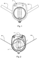
Fig. 1 is a front view of the present invention; -
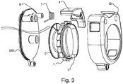
Fig. 2 is an internal structure diagram of the present invention; -
Fig. 3 is an exploded view of the present invention; and -
Fig. 4 is a schematic diagram of a baby carriage according to the present invention. - The present invention will be specifically described with reference to specific embodiments.
- As shown in
Fig. 1 to Fig. 4 , a backrest adjustor is provided, including a shell, arotarygear 1 located inside the shell, awinding wheel 2 which is driven by thegear 1 and located inside the shell, aknob 3 for driving thegear 1 to rotate, and abutton 4 capable of controlling thegear 1 to rotate, moving and being reset by a reset component. A rotating portion of theknob 3 is exposed outside the shell. The shell includes anupper cover 101 and alower cover 102, which are connected to each other to form the shell. Of course, the shell may be formed from multiple connected portions. - The backrest adjustor further includes two
ribbons frame 6 of a baby carriage extend from the shell and are then wound around the outer face of abackrest 5. - The
winding wheel 2, thegear 1 and theknob 3 are coaxial and formed integrally, so that the backrest adjustor is compact in structure and space-saving. Thewinding wheel 2 is located on the inner side of thegear 1. - The reset component is a
torsion spring 7 which is in contact with thebutton 4. A portion of thebutton 4 may extend into a tooth slot of thegear 1. Thebutton 4 is provided with a member to be pressed which is exposed outside the shell. Thebutton 4 is mounted on a rotatingcolumn 8 disposed inside the shell. Of course, thebutton 4 may be mounted by other conventional methods. - The position relationship between the gear and the button contributes to a ratchet structure.
- The working principle will be described as below. First, the
gear 1 is rotated and the ribbons are wound on the winding wheel, so that the ascending of the backrest is realized by adjusting the length of the ribbons. The button is blocked on the gear under the action of the torsion spring, so that the reverse rotation of the gear is avoided. Therefore, the backrest adjustor is simple in structure and convenient and easy in adjustment, and may be adjusted by a single hand. Second, release operation: the button is pressed down by a hand and then the button is disengaged from the gear, so that the gear may rotate reversely and the ribbons may be pulled out, realizing the lying of thebackrest 5. - As another embodiment, the characteristic lies in that: in this embodiment, one ribbon is utilized, the middle segment of which is wound on the winding wheel while two ends of which used for connecting a frame of a baby carriage extend from the shell and are then wound around the outer face of a backrest.
- As another embodiment, the characteristic lies in that: the winding wheel is located between the gear and the knob. A simple structure is realized.
- As another embodiment, as shown in
Fig. 4 , a baby carriage is provided, including aframe 6 having abackrest 5 provided thereon, and further including the backrest adjustor described above. The backrest adjustor is located on the outer side of the backrest, and aribbon 10 of the backrest adjustor is connected to frame. - The forgoing description merely shows the specific embodiments of the present invention, and the protection scope of the present invention is not limited thereto. Any variation or displacement readily thought by those of ordinary skill in the art upon the disclosure of the present invention shall fall into the protection scope of the present invention. Therefore, the protection scope of the present invention shall be subject to the appended claims.
Claims (9)
- A backrest adjustor, comprising a shell, a rotary gear (1) located inside the shell, a winding wheel (2) which is driven by the gear (1) and located inside the shell, and a button (4) capable of controlling the gear (1) to rotate, moving and being reset by a reset component,; the backrest adjustor further comprising a ribbon (10), the middle segment of the ribbon (10) being wound on the winding wheel (2), two ends of the ribbon (10) suitable for connecting to a frame (6) of a baby carriage are extending from the shell and being adapted to be wound around the outer face of a backrest (5); or, the backrest adjustor further comprising two ribbons (501, 502), one end of each being separately wound on the winding wheel (2) and the other end of each suitable for connecting to a frame (6) of the baby carriage extending from the shell separately and being adapted to be wound around the outer face of the backrest (5),
characterized in comprising a knob (3) for driving the gear (1) to rotate, a rotating portion of the knob (3) being exposed outside the shell. - The backrest adjustor according to claim 1, wherein the winding wheel (2), the gear (1) and the knob (3) are coaxial and formed integrally.
- The backrest adjustor according to claim 2, wherein the winding wheel (2) is located on the inner side of the gear (1).
- The backrest adjustor according to claim 2, wherein the winding wheel (2) is located between the gear (1) and the knob (3).
- The backrest adjustor according to one of claims 1 to 4, wherein the reset component is a torsion spring (7) which is in contact with the button (4), a portion of the button (4) can extend into a tooth slot of the gear (1), and the button (4) is provided with a member to be pressed which is exposed outside the shell.
- The backrest adjustor according to claim 5, wherein the button (4) is mounted on a rotating column (8) disposed inside the shell.
- The backrest adjustor according to one of claims 1 to 6, wherein the shell comprises an upper cover (101) and a lower cover (102), which are connected to each other to form the shell.
- The backrest adjustor according to one of claims 1 to 7, wherein the position relationship between the gear (1) and the button (4) contributes to a ratchet structure.
- A baby carriage, comprising a frame (6) having a backrest (5) provided thereon, and further comprising the backrest adjustor according to any one of claims 1-7, the backrest adjustor being located on an outer side of the backrest (5), corresponding ends of a ribbon (10) in the backrest adjustor being connected to the frame (6).
Applications Claiming Priority (1)
| Application Number | Priority Date | Filing Date | Title |
|---|---|---|---|
| CN201320772970.4U CN203601347U (en) | 2013-11-28 | 2013-11-28 | Backrest adjusters and buggies |
Publications (3)
| Publication Number | Publication Date |
|---|---|
| EP2878513A2 EP2878513A2 (en) | 2015-06-03 |
| EP2878513A3 EP2878513A3 (en) | 2016-01-06 |
| EP2878513B1 true EP2878513B1 (en) | 2017-05-31 |
Family
ID=50714039
Family Applications (1)
| Application Number | Title | Priority Date | Filing Date |
|---|---|---|---|
| EP14195108.7A Active EP2878513B1 (en) | 2013-11-28 | 2014-11-27 | Backrest adjustor and baby carriage including such a backrest adjustor |
Country Status (3)
| Country | Link |
|---|---|
| US (1) | US20150145304A1 (en) |
| EP (1) | EP2878513B1 (en) |
| CN (1) | CN203601347U (en) |
Families Citing this family (6)
| Publication number | Priority date | Publication date | Assignee | Title |
|---|---|---|---|---|
| CN204415493U (en) * | 2015-01-29 | 2015-06-24 | 嘉兴小虎子车业有限公司 | A kind of Back of perambulator control apparatus of cloth bag type |
| NL2016451B1 (en) * | 2016-03-17 | 2017-10-05 | Mutsy Bv | Device for transporting a child and child seat |
| CN108860281A (en) * | 2018-07-06 | 2018-11-23 | 昆山市贝尔儿童用品有限公司 | Stroller seat pocket and stroller |
| CN109017962A (en) * | 2018-09-08 | 2018-12-18 | 卢键平 | Applied to the backrest stepless regulator on stroller seat |
| US20230022623A1 (en) * | 2019-12-05 | 2023-01-26 | Endepro Gmbh | Device for adjusting the inclination of an object |
| CN115303354A (en) * | 2021-05-07 | 2022-11-08 | 哥瑞考儿童产品公司 | Child-care implement with seat |
Family Cites Families (13)
| Publication number | Priority date | Publication date | Assignee | Title |
|---|---|---|---|---|
| GB2178306A (en) * | 1985-08-02 | 1987-02-11 | Quaker Oats Co | An adjustable back reclining mechanism for a baby stroller |
| US5634380A (en) * | 1994-03-31 | 1997-06-03 | Keiper Recaro Gmbh & Co. | Articulated fitting for seats with adjustable backrest in particular for motor vehicle seats |
| JP3540952B2 (en) * | 1998-12-21 | 2004-07-07 | 富士機工株式会社 | Adjustment and fixing devices for vehicle seat devices |
| JP4650658B2 (en) * | 2001-09-20 | 2011-03-16 | 株式会社フォルム | Reclining device for stroller |
| US6869143B2 (en) * | 2003-04-01 | 2005-03-22 | Bae Industries, Inc. | Recliner clutch mechanism for vehicle seat |
| DE102004015234B4 (en) * | 2004-03-26 | 2011-01-13 | Faurecia Autositze Gmbh | Inclination adjustment fitting with free-pivoting device for the backrest of a motor vehicle seat |
| CA2562786A1 (en) * | 2004-04-30 | 2005-11-17 | Pdp Compass, Llc | Foldable stroller |
| EP2001709B1 (en) * | 2006-04-03 | 2010-11-10 | Graco Children's Products Inc. | Cup holder for a stroller |
| CN101070055B (en) * | 2006-05-11 | 2011-06-08 | 湖北中航精机科技股份有限公司 | Gear-type chair angle stepless regulation structure |
| JP4968776B2 (en) * | 2006-08-18 | 2012-07-04 | テイ・エス テック株式会社 | Vehicle seat |
| DE102007007362B4 (en) * | 2007-02-14 | 2009-07-09 | Faurecia Autositze Gmbh | adjustment |
| DE112010004681T5 (en) * | 2009-12-04 | 2013-02-14 | Fisher & Company, Inc. | Seat mechanism with easy access function |
| US8870213B1 (en) * | 2013-05-20 | 2014-10-28 | Dongguang Master Kids Toy Co., Ltd. | Single-hand foldable baby stroller |
-
2013
- 2013-11-28 CN CN201320772970.4U patent/CN203601347U/en not_active Expired - Lifetime
-
2014
- 2014-11-27 EP EP14195108.7A patent/EP2878513B1/en active Active
- 2014-11-27 US US14/555,641 patent/US20150145304A1/en not_active Abandoned
Non-Patent Citations (1)
| Title |
|---|
| None * |
Also Published As
| Publication number | Publication date |
|---|---|
| CN203601347U (en) | 2014-05-21 |
| US20150145304A1 (en) | 2015-05-28 |
| EP2878513A3 (en) | 2016-01-06 |
| EP2878513A2 (en) | 2015-06-03 |
Similar Documents
| Publication | Publication Date | Title |
|---|---|---|
| EP2878513A2 (en) | Backrest adjustor and baby carriage including such a backrest adjustor | |
| US9127500B2 (en) | Cord-winding device for venetian blind | |
| EP3345509B1 (en) | New portable baby sleeping bag | |
| GB2470819A (en) | Fabric gate | |
| CN204393535U (en) | Flexible ribbon line wheel | |
| TWM373187U (en) | Bead chain safety device for roller blinds | |
| CN205059705U (en) | Convenient singlehanded angle regulation's perambulator seat | |
| CN203221904U (en) | Child safety chair for vehicle | |
| CN104527528A (en) | Containing box and vehicle | |
| CN110481629A (en) | A kind of children trolley | |
| KR101504111B1 (en) | A bicycle having front wheel driving device | |
| CN209733200U (en) | Lifting bed guardrail capable of being operated by single hand | |
| CN203066616U (en) | Improved lever handle | |
| CN206243357U (en) | The adjustable foldable handlebar of button | |
| CN203228824U (en) | Mechanical stroller seat reversing structure | |
| CN203438690U (en) | Automatic pipe feeding mechanism for bookbinding machine | |
| WO2024066645A1 (en) | Bicycle steering structure and bicycle | |
| CN204055893U (en) | Children trolley | |
| CN210681013U (en) | Baby carriage with adjustable handle angle function | |
| CN203206438U (en) | Pull-wire earphone | |
| CN204236525U (en) | Children trolley | |
| EP3748178A1 (en) | Device for securing a rider to a bicycle | |
| CN202130423U (en) | Safety belt with pre-tightening caution device | |
| WO2016101893A1 (en) | Folding device of baby carrier wheel | |
| CN209915526U (en) | A two-way adjustment mechanism that can be operated with one hand |
Legal Events
| Date | Code | Title | Description |
|---|---|---|---|
| PUAI | Public reference made under article 153(3) epc to a published international application that has entered the european phase |
Free format text: ORIGINAL CODE: 0009012 |
|
| 17P | Request for examination filed |
Effective date: 20141127 |
|
| AK | Designated contracting states |
Kind code of ref document: A2 Designated state(s): AL AT BE BG CH CY CZ DE DK EE ES FI FR GB GR HR HU IE IS IT LI LT LU LV MC MK MT NL NO PL PT RO RS SE SI SK SM TR |
|
| AX | Request for extension of the european patent |
Extension state: BA ME |
|
| PUAL | Search report despatched |
Free format text: ORIGINAL CODE: 0009013 |
|
| AK | Designated contracting states |
Kind code of ref document: A3 Designated state(s): AL AT BE BG CH CY CZ DE DK EE ES FI FR GB GR HR HU IE IS IT LI LT LU LV MC MK MT NL NO PL PT RO RS SE SI SK SM TR |
|
| AX | Request for extension of the european patent |
Extension state: BA ME |
|
| RIC1 | Information provided on ipc code assigned before grant |
Ipc: B62B 9/10 20060101AFI20151130BHEP |
|
| R17P | Request for examination filed (corrected) |
Effective date: 20160628 |
|
| RBV | Designated contracting states (corrected) |
Designated state(s): AL AT BE BG CH CY CZ DE DK EE ES FI FR GB GR HR HU IE IS IT LI LT LU LV MC MK MT NL NO PL PT RO RS SE SI SK SM TR |
|
| GRAP | Despatch of communication of intention to grant a patent |
Free format text: ORIGINAL CODE: EPIDOSNIGR1 |
|
| INTG | Intention to grant announced |
Effective date: 20161128 |
|
| GRAS | Grant fee paid |
Free format text: ORIGINAL CODE: EPIDOSNIGR3 |
|
| GRAJ | Information related to disapproval of communication of intention to grant by the applicant or resumption of examination proceedings by the epo deleted |
Free format text: ORIGINAL CODE: EPIDOSDIGR1 |
|
| GRAL | Information related to payment of fee for publishing/printing deleted |
Free format text: ORIGINAL CODE: EPIDOSDIGR3 |
|
| GRAR | Information related to intention to grant a patent recorded |
Free format text: ORIGINAL CODE: EPIDOSNIGR71 |
|
| GRAA | (expected) grant |
Free format text: ORIGINAL CODE: 0009210 |
|
| INTC | Intention to grant announced (deleted) | ||
| AK | Designated contracting states |
Kind code of ref document: B1 Designated state(s): AL AT BE BG CH CY CZ DE DK EE ES FI FR GB GR HR HU IE IS IT LI LT LU LV MC MK MT NL NO PL PT RO RS SE SI SK SM TR |
|
| INTG | Intention to grant announced |
Effective date: 20170424 |
|
| REG | Reference to a national code |
Ref country code: CH Ref legal event code: EP Ref country code: GB Ref legal event code: FG4D |
|
| REG | Reference to a national code |
Ref country code: AT Ref legal event code: REF Ref document number: 897167 Country of ref document: AT Kind code of ref document: T Effective date: 20170615 |
|
| REG | Reference to a national code |
Ref country code: IE Ref legal event code: FG4D |
|
| REG | Reference to a national code |
Ref country code: DE Ref legal event code: R096 Ref document number: 602014010234 Country of ref document: DE |
|
| REG | Reference to a national code |
Ref country code: NL Ref legal event code: MP Effective date: 20170531 |
|
| REG | Reference to a national code |
Ref country code: LT Ref legal event code: MG4D |
|
| REG | Reference to a national code |
Ref country code: AT Ref legal event code: MK05 Ref document number: 897167 Country of ref document: AT Kind code of ref document: T Effective date: 20170531 |
|
| PG25 | Lapsed in a contracting state [announced via postgrant information from national office to epo] |
Ref country code: AT Free format text: LAPSE BECAUSE OF FAILURE TO SUBMIT A TRANSLATION OF THE DESCRIPTION OR TO PAY THE FEE WITHIN THE PRESCRIBED TIME-LIMIT Effective date: 20170531 Ref country code: HR Free format text: LAPSE BECAUSE OF FAILURE TO SUBMIT A TRANSLATION OF THE DESCRIPTION OR TO PAY THE FEE WITHIN THE PRESCRIBED TIME-LIMIT Effective date: 20170531 Ref country code: NO Free format text: LAPSE BECAUSE OF FAILURE TO SUBMIT A TRANSLATION OF THE DESCRIPTION OR TO PAY THE FEE WITHIN THE PRESCRIBED TIME-LIMIT Effective date: 20170831 Ref country code: FI Free format text: LAPSE BECAUSE OF FAILURE TO SUBMIT A TRANSLATION OF THE DESCRIPTION OR TO PAY THE FEE WITHIN THE PRESCRIBED TIME-LIMIT Effective date: 20170531 Ref country code: GR Free format text: LAPSE BECAUSE OF FAILURE TO SUBMIT A TRANSLATION OF THE DESCRIPTION OR TO PAY THE FEE WITHIN THE PRESCRIBED TIME-LIMIT Effective date: 20170901 Ref country code: LT Free format text: LAPSE BECAUSE OF FAILURE TO SUBMIT A TRANSLATION OF THE DESCRIPTION OR TO PAY THE FEE WITHIN THE PRESCRIBED TIME-LIMIT Effective date: 20170531 Ref country code: ES Free format text: LAPSE BECAUSE OF FAILURE TO SUBMIT A TRANSLATION OF THE DESCRIPTION OR TO PAY THE FEE WITHIN THE PRESCRIBED TIME-LIMIT Effective date: 20170531 |
|
| REG | Reference to a national code |
Ref country code: FR Ref legal event code: PLFP Year of fee payment: 4 |
|
| PG25 | Lapsed in a contracting state [announced via postgrant information from national office to epo] |
Ref country code: LV Free format text: LAPSE BECAUSE OF FAILURE TO SUBMIT A TRANSLATION OF THE DESCRIPTION OR TO PAY THE FEE WITHIN THE PRESCRIBED TIME-LIMIT Effective date: 20170531 Ref country code: NL Free format text: LAPSE BECAUSE OF FAILURE TO SUBMIT A TRANSLATION OF THE DESCRIPTION OR TO PAY THE FEE WITHIN THE PRESCRIBED TIME-LIMIT Effective date: 20170531 Ref country code: RS Free format text: LAPSE BECAUSE OF FAILURE TO SUBMIT A TRANSLATION OF THE DESCRIPTION OR TO PAY THE FEE WITHIN THE PRESCRIBED TIME-LIMIT Effective date: 20170531 Ref country code: IS Free format text: LAPSE BECAUSE OF FAILURE TO SUBMIT A TRANSLATION OF THE DESCRIPTION OR TO PAY THE FEE WITHIN THE PRESCRIBED TIME-LIMIT Effective date: 20170930 Ref country code: SE Free format text: LAPSE BECAUSE OF FAILURE TO SUBMIT A TRANSLATION OF THE DESCRIPTION OR TO PAY THE FEE WITHIN THE PRESCRIBED TIME-LIMIT Effective date: 20170531 Ref country code: BG Free format text: LAPSE BECAUSE OF FAILURE TO SUBMIT A TRANSLATION OF THE DESCRIPTION OR TO PAY THE FEE WITHIN THE PRESCRIBED TIME-LIMIT Effective date: 20170831 |
|
| PG25 | Lapsed in a contracting state [announced via postgrant information from national office to epo] |
Ref country code: SK Free format text: LAPSE BECAUSE OF FAILURE TO SUBMIT A TRANSLATION OF THE DESCRIPTION OR TO PAY THE FEE WITHIN THE PRESCRIBED TIME-LIMIT Effective date: 20170531 Ref country code: DK Free format text: LAPSE BECAUSE OF FAILURE TO SUBMIT A TRANSLATION OF THE DESCRIPTION OR TO PAY THE FEE WITHIN THE PRESCRIBED TIME-LIMIT Effective date: 20170531 Ref country code: RO Free format text: LAPSE BECAUSE OF FAILURE TO SUBMIT A TRANSLATION OF THE DESCRIPTION OR TO PAY THE FEE WITHIN THE PRESCRIBED TIME-LIMIT Effective date: 20170531 Ref country code: EE Free format text: LAPSE BECAUSE OF FAILURE TO SUBMIT A TRANSLATION OF THE DESCRIPTION OR TO PAY THE FEE WITHIN THE PRESCRIBED TIME-LIMIT Effective date: 20170531 Ref country code: CZ Free format text: LAPSE BECAUSE OF FAILURE TO SUBMIT A TRANSLATION OF THE DESCRIPTION OR TO PAY THE FEE WITHIN THE PRESCRIBED TIME-LIMIT Effective date: 20170531 |
|
| PG25 | Lapsed in a contracting state [announced via postgrant information from national office to epo] |
Ref country code: SM Free format text: LAPSE BECAUSE OF FAILURE TO SUBMIT A TRANSLATION OF THE DESCRIPTION OR TO PAY THE FEE WITHIN THE PRESCRIBED TIME-LIMIT Effective date: 20170531 Ref country code: PL Free format text: LAPSE BECAUSE OF FAILURE TO SUBMIT A TRANSLATION OF THE DESCRIPTION OR TO PAY THE FEE WITHIN THE PRESCRIBED TIME-LIMIT Effective date: 20170531 Ref country code: IT Free format text: LAPSE BECAUSE OF FAILURE TO SUBMIT A TRANSLATION OF THE DESCRIPTION OR TO PAY THE FEE WITHIN THE PRESCRIBED TIME-LIMIT Effective date: 20170531 |
|
| REG | Reference to a national code |
Ref country code: DE Ref legal event code: R097 Ref document number: 602014010234 Country of ref document: DE |
|
| PLBE | No opposition filed within time limit |
Free format text: ORIGINAL CODE: 0009261 |
|
| STAA | Information on the status of an ep patent application or granted ep patent |
Free format text: STATUS: NO OPPOSITION FILED WITHIN TIME LIMIT |
|
| 26N | No opposition filed |
Effective date: 20180301 |
|
| PG25 | Lapsed in a contracting state [announced via postgrant information from national office to epo] |
Ref country code: SI Free format text: LAPSE BECAUSE OF FAILURE TO SUBMIT A TRANSLATION OF THE DESCRIPTION OR TO PAY THE FEE WITHIN THE PRESCRIBED TIME-LIMIT Effective date: 20170531 |
|
| PG25 | Lapsed in a contracting state [announced via postgrant information from national office to epo] |
Ref country code: MC Free format text: LAPSE BECAUSE OF FAILURE TO SUBMIT A TRANSLATION OF THE DESCRIPTION OR TO PAY THE FEE WITHIN THE PRESCRIBED TIME-LIMIT Effective date: 20170531 |
|
| PG25 | Lapsed in a contracting state [announced via postgrant information from national office to epo] |
Ref country code: CH Free format text: LAPSE BECAUSE OF NON-PAYMENT OF DUE FEES Effective date: 20171130 Ref country code: LI Free format text: LAPSE BECAUSE OF NON-PAYMENT OF DUE FEES Effective date: 20171130 |
|
| PG25 | Lapsed in a contracting state [announced via postgrant information from national office to epo] |
Ref country code: LU Free format text: LAPSE BECAUSE OF NON-PAYMENT OF DUE FEES Effective date: 20171127 |
|
| REG | Reference to a national code |
Ref country code: BE Ref legal event code: MM Effective date: 20171130 |
|
| REG | Reference to a national code |
Ref country code: IE Ref legal event code: MM4A |
|
| PG25 | Lapsed in a contracting state [announced via postgrant information from national office to epo] |
Ref country code: MT Free format text: LAPSE BECAUSE OF NON-PAYMENT OF DUE FEES Effective date: 20171127 |
|
| PG25 | Lapsed in a contracting state [announced via postgrant information from national office to epo] |
Ref country code: IE Free format text: LAPSE BECAUSE OF NON-PAYMENT OF DUE FEES Effective date: 20171127 |
|
| PG25 | Lapsed in a contracting state [announced via postgrant information from national office to epo] |
Ref country code: BE Free format text: LAPSE BECAUSE OF NON-PAYMENT OF DUE FEES Effective date: 20171130 |
|
| PG25 | Lapsed in a contracting state [announced via postgrant information from national office to epo] |
Ref country code: HU Free format text: LAPSE BECAUSE OF FAILURE TO SUBMIT A TRANSLATION OF THE DESCRIPTION OR TO PAY THE FEE WITHIN THE PRESCRIBED TIME-LIMIT; INVALID AB INITIO Effective date: 20141127 |
|
| PG25 | Lapsed in a contracting state [announced via postgrant information from national office to epo] |
Ref country code: CY Free format text: LAPSE BECAUSE OF FAILURE TO SUBMIT A TRANSLATION OF THE DESCRIPTION OR TO PAY THE FEE WITHIN THE PRESCRIBED TIME-LIMIT Effective date: 20170531 |
|
| PG25 | Lapsed in a contracting state [announced via postgrant information from national office to epo] |
Ref country code: MK Free format text: LAPSE BECAUSE OF FAILURE TO SUBMIT A TRANSLATION OF THE DESCRIPTION OR TO PAY THE FEE WITHIN THE PRESCRIBED TIME-LIMIT Effective date: 20170531 |
|
| PG25 | Lapsed in a contracting state [announced via postgrant information from national office to epo] |
Ref country code: TR Free format text: LAPSE BECAUSE OF FAILURE TO SUBMIT A TRANSLATION OF THE DESCRIPTION OR TO PAY THE FEE WITHIN THE PRESCRIBED TIME-LIMIT Effective date: 20170531 |
|
| PG25 | Lapsed in a contracting state [announced via postgrant information from national office to epo] |
Ref country code: PT Free format text: LAPSE BECAUSE OF FAILURE TO SUBMIT A TRANSLATION OF THE DESCRIPTION OR TO PAY THE FEE WITHIN THE PRESCRIBED TIME-LIMIT Effective date: 20170531 |
|
| PG25 | Lapsed in a contracting state [announced via postgrant information from national office to epo] |
Ref country code: AL Free format text: LAPSE BECAUSE OF FAILURE TO SUBMIT A TRANSLATION OF THE DESCRIPTION OR TO PAY THE FEE WITHIN THE PRESCRIBED TIME-LIMIT Effective date: 20170531 |
|
| PGFP | Annual fee paid to national office [announced via postgrant information from national office to epo] |
Ref country code: DE Payment date: 20251021 Year of fee payment: 12 |
|
| PGFP | Annual fee paid to national office [announced via postgrant information from national office to epo] |
Ref country code: GB Payment date: 20251016 Year of fee payment: 12 |
|
| PGFP | Annual fee paid to national office [announced via postgrant information from national office to epo] |
Ref country code: FR Payment date: 20251011 Year of fee payment: 12 |