EP2878494A1 - Housing for at least one electrical component - Google Patents
Housing for at least one electrical component Download PDFInfo
- Publication number
- EP2878494A1 EP2878494A1 EP14194762.2A EP14194762A EP2878494A1 EP 2878494 A1 EP2878494 A1 EP 2878494A1 EP 14194762 A EP14194762 A EP 14194762A EP 2878494 A1 EP2878494 A1 EP 2878494A1
- Authority
- EP
- European Patent Office
- Prior art keywords
- housing
- contact
- contact surface
- adhesive
- mating
- Prior art date
- Legal status (The legal status is an assumption and is not a legal conclusion. Google has not performed a legal analysis and makes no representation as to the accuracy of the status listed.)
- Granted
Links
- 230000013011 mating Effects 0.000 claims abstract description 24
- 239000000853 adhesive Substances 0.000 claims description 27
- 230000001070 adhesive effect Effects 0.000 claims description 26
- 238000007789 sealing Methods 0.000 claims description 10
- 239000006260 foam Substances 0.000 claims description 9
- 238000000034 method Methods 0.000 claims description 8
- XLYOFNOQVPJJNP-UHFFFAOYSA-N water Substances O XLYOFNOQVPJJNP-UHFFFAOYSA-N 0.000 claims description 4
- 239000002390 adhesive tape Substances 0.000 claims description 3
- 230000003287 optical effect Effects 0.000 claims description 2
- 229920001296 polysiloxane Polymers 0.000 claims description 2
- 230000008901 benefit Effects 0.000 description 6
- 239000000463 material Substances 0.000 description 4
- 230000009467 reduction Effects 0.000 description 4
- 238000004891 communication Methods 0.000 description 3
- 230000000694 effects Effects 0.000 description 3
- 230000004913 activation Effects 0.000 description 2
- 230000005489 elastic deformation Effects 0.000 description 2
- 230000008569 process Effects 0.000 description 2
- 230000009471 action Effects 0.000 description 1
- 230000002411 adverse Effects 0.000 description 1
- 230000015572 biosynthetic process Effects 0.000 description 1
- 239000011248 coating agent Substances 0.000 description 1
- 238000000576 coating method Methods 0.000 description 1
- 230000006835 compression Effects 0.000 description 1
- 238000007906 compression Methods 0.000 description 1
- 238000005260 corrosion Methods 0.000 description 1
- 230000007797 corrosion Effects 0.000 description 1
- 230000008878 coupling Effects 0.000 description 1
- 238000010168 coupling process Methods 0.000 description 1
- 238000005859 coupling reaction Methods 0.000 description 1
- 230000001419 dependent effect Effects 0.000 description 1
- 238000001514 detection method Methods 0.000 description 1
- 230000007613 environmental effect Effects 0.000 description 1
- 210000004907 gland Anatomy 0.000 description 1
- 238000005286 illumination Methods 0.000 description 1
- 238000009434 installation Methods 0.000 description 1
- 238000004519 manufacturing process Methods 0.000 description 1
- 230000007246 mechanism Effects 0.000 description 1
- 239000003973 paint Substances 0.000 description 1
- 239000011253 protective coating Substances 0.000 description 1
Images


Classifications
-
- H—ELECTRICITY
- H02—GENERATION; CONVERSION OR DISTRIBUTION OF ELECTRIC POWER
- H02K—DYNAMO-ELECTRIC MACHINES
- H02K5/00—Casings; Enclosures; Supports
- H02K5/04—Casings or enclosures characterised by the shape, form or construction thereof
-
- B—PERFORMING OPERATIONS; TRANSPORTING
- B60—VEHICLES IN GENERAL
- B60R—VEHICLES, VEHICLE FITTINGS, OR VEHICLE PARTS, NOT OTHERWISE PROVIDED FOR
- B60R16/00—Electric or fluid circuits specially adapted for vehicles and not otherwise provided for; Arrangement of elements of electric or fluid circuits specially adapted for vehicles and not otherwise provided for
- B60R16/02—Electric or fluid circuits specially adapted for vehicles and not otherwise provided for; Arrangement of elements of electric or fluid circuits specially adapted for vehicles and not otherwise provided for electric constitutive elements
- B60R16/023—Electric or fluid circuits specially adapted for vehicles and not otherwise provided for; Arrangement of elements of electric or fluid circuits specially adapted for vehicles and not otherwise provided for electric constitutive elements for transmission of signals between vehicle parts or subsystems
- B60R16/0239—Electronic boxes
-
- F—MECHANICAL ENGINEERING; LIGHTING; HEATING; WEAPONS; BLASTING
- F16—ENGINEERING ELEMENTS AND UNITS; GENERAL MEASURES FOR PRODUCING AND MAINTAINING EFFECTIVE FUNCTIONING OF MACHINES OR INSTALLATIONS; THERMAL INSULATION IN GENERAL
- F16M—FRAMES, CASINGS OR BEDS OF ENGINES, MACHINES OR APPARATUS, NOT SPECIFIC TO ENGINES, MACHINES OR APPARATUS PROVIDED FOR ELSEWHERE; STANDS; SUPPORTS
- F16M13/00—Other supports for positioning apparatus or articles; Means for steadying hand-held apparatus or articles
- F16M13/02—Other supports for positioning apparatus or articles; Means for steadying hand-held apparatus or articles for supporting on, or attaching to, an object, e.g. tree, gate, window-frame, cycle
-
- H—ELECTRICITY
- H02—GENERATION; CONVERSION OR DISTRIBUTION OF ELECTRIC POWER
- H02K—DYNAMO-ELECTRIC MACHINES
- H02K5/00—Casings; Enclosures; Supports
- H02K5/04—Casings or enclosures characterised by the shape, form or construction thereof
- H02K5/10—Casings or enclosures characterised by the shape, form or construction thereof with arrangements for protection from ingress, e.g. water or fingers
-
- H—ELECTRICITY
- H05—ELECTRIC TECHNIQUES NOT OTHERWISE PROVIDED FOR
- H05K—PRINTED CIRCUITS; CASINGS OR CONSTRUCTIONAL DETAILS OF ELECTRIC APPARATUS; MANUFACTURE OF ASSEMBLAGES OF ELECTRICAL COMPONENTS
- H05K5/00—Casings, cabinets or drawers for electric apparatus
- H05K5/0026—Casings, cabinets or drawers for electric apparatus provided with connectors and printed circuit boards [PCB], e.g. automotive electronic control units
- H05K5/0069—Casings, cabinets or drawers for electric apparatus provided with connectors and printed circuit boards [PCB], e.g. automotive electronic control units having connector relating features for connecting the connector pins with the PCB or for mounting the connector body with the housing
-
- H—ELECTRICITY
- H05—ELECTRIC TECHNIQUES NOT OTHERWISE PROVIDED FOR
- H05K—PRINTED CIRCUITS; CASINGS OR CONSTRUCTIONAL DETAILS OF ELECTRIC APPARATUS; MANUFACTURE OF ASSEMBLAGES OF ELECTRICAL COMPONENTS
- H05K5/00—Casings, cabinets or drawers for electric apparatus
- H05K5/0026—Casings, cabinets or drawers for electric apparatus provided with connectors and printed circuit boards [PCB], e.g. automotive electronic control units
- H05K5/0073—Casings, cabinets or drawers for electric apparatus provided with connectors and printed circuit boards [PCB], e.g. automotive electronic control units having specific features for mounting the housing on an external structure
Definitions
- the present invention relates to a housing for at least one electrical component, in particular an electromechanical component, for mounting in or on a vehicle, as well as a switching component with a housing for attachment to a vehicle and a method for fastening a switching component to the body of a vehicle.
- housing should be mounted in a vehicle, which have electronic components.
- the electronic components are often electromechanical switching components, ie switching elements which can be operated by the occupant of the vehicle.
- These housings are often designed so that they must withstand adverse environmental conditions.
- In addition to an arrangement in the interior are also arrangements on the outside of the body, z. B. in the field of door handles or the opening mechanism for the trunk in question.
- a housing for at least one electrical component, in particular an electromechanical switching component for mounting in or on a vehicle.
- the housing has a housing wall which surrounds a housing interior.
- the housing is characterized according to the invention in that on the housing wall at least one outwardly directed contact element is arranged with at least one contact surface for fastening contacting on a mating contact surface.
- the mating contact surface is preferably part of the body of the vehicle.
- An inventive housing thus serves to protect electrical components or in particular electromechanical switching components.
- the housing wall or a part of the housing wall is preferably formed impermeable to water.
- the housing can also have further components, in particular in the form of sealing means, in order to form the entire housing in a watertight or substantially watertight manner with respect to the housing interior. It should be noted that for possibly necessary pressure equalization situations, of course, the housing wall or other components of the housing a corresponding pressure equalization, for. B. with the help of a vent.
- the housing interior thus serves as a receiving space for the electrical component. If the electrical component is an electromechanical switching component, this can convert a mechanical actuation into an electrical signal.
- This is z. B. for unlocking and the opening process in an automated manner for the tailgate of a vehicle conceivable. So z. B. an inventive housing having a corresponding contact switch as a mechanical switching device for opening the tailgate.
- the housing which has at least one electrical component in its housing interior, must accordingly be fastened to the bodywork at the desired position on the tailgate.
- the advantage according to the invention becomes particularly clear. So now no longer has to be done in a complex way screwing the finished housing, so the housing with the electrical component housed therein, with the body. Rather, can be done by the presence of the housing wall outwardly directed contact element, a simple contacting of the contact surface with the mating contact surface. This creates the fastening contact without additional funds, in particular without additional screwing.
- each element which allows a fastening effect in the contact between the contact surface and the mating contact surface.
- Two preferred solutions for a contact element with contact surfaces are described below. So can the contact element in particular be designed as an adhesive element with at least one adhesive surface, so that the fastening contacting represents a bond with the mating contact surface. It is also a possibility if the contact element is designed as a latching element, wherein this forms a latching surface for the latched fixed contacting a mating contact surface in the form of a counter-latching surface.
- the at least one contact element is designed as a latching element with at least one contact surface in the form of a latching surface for latching contacting with a mating contact surface in the form of a counter-latching surface.
- a latching element thus serves to allow a movement of the housing in its mounting position by an elastic deformation from a detent position to a release position.
- the housing is in the mounting position is moved by elastic restoring forces within the locking element of this from its release position back into its locking position, so that now the locking surface with the counter-locking surface on the body forms a latching contact.
- a housing of this embodiment is simple, inexpensive and above all pressed quickly into a corresponding detent opening of the body and locked.
- a contact element may have two or more functionalities.
- the latching surface of the latching element can be provided simultaneously with an adhesive and thus also act as an adhesive surface in the form of a contact surface.
- the at least one contact element is designed as an adhesive element with at least one contact surface in the form of an adhesive surface for adhesive contacting with a mating contact surface in the form of a counter-adhesive surface.
- an adhesive element with at least one contact surface in the form of an adhesive surface for adhesive contacting with a mating contact surface in the form of a counter-adhesive surface.
- the surface of the adhesive surface is preferably processed or provided with adhesive.
- the surface structure can be prepared, in particular roughened, in order to achieve an improved adhesive effect.
- the adhesive surface itself may have the adhesive to z. B. on pressure activation or heat activation to activate the adhesive effect.
- a further advantage can be achieved if, in a housing according to the invention, an outwardly directed flexible compensation element is arranged on the housing wall, which surrounds the at least one contact element, in particular at least in sections.
- a flexible compensation element is formed on the compensation in an elastically deforming manner of the own material for geometric differences between the housing wall and the adjacent body.
- a flexible compensation element can be provided, which can compensate for such inequalities and tolerances by flexible and thus elastic deformation of its own material.
- such a flexible compensation element is also effective or designed as a sealing element.
- the flexible compensation element can provide protection by its elastic deformability.
- the flexible compensation element can, for. B. in the form of a compensation pads be formed substantially flat.
- the flexible compensation element comprises a plastic material on.
- the flexible compensation element is in particular attached at least temporarily to the housing wall.
- a simple bond may be provided that for the contacting attachment, the arrangement of the flexible compensation element with high probability also remains at the desired position.
- the compensation element may preferably form a structural unit with the contact element.
- compensating element and contact element can be formed integrally with one another, that is to say in one piece or monolithically.
- the compensation element has a thickness which correlates with the contact surface in such a way that, when the contacting contact surface is fixed by the contact surface of the contact element, a sealing force, in particular in an elastically deforming manner, acts on the compensation element.
- the geometric correlation between mating contact surface and contact surface and the thickness of the compensating element form a final assembly situation, which preferably leads to an elastically deformed reduction of the thickness of the compensating element in the mounting situation.
- acts in the assembled situation a sealing force on the compensating element, so now there is a seal of a corresponding mounting hole or a corresponding mounting hole in the body against the ingress of water. This leads to a reduction of the risk of corrosion of this body area.
- the compensation element is annular and surrounds the at least one contact element.
- the surrounding can have very different geometries.
- the compensating element can surround the contact element in a round, angular or other annular shape.
- all contact elements are individually or all contact elements together completely surrounded by one or more compensation elements. This leads, so to speak, to a seal around all contact elements. Since usually for each contact element or for all contact elements together a corresponding mating contact opening is provided within the body, such an embodiment acts sealingly against this mating contact opening of the body.
- the list above is a non-exhaustive list.
- different compensation elements can be combined with each other to form one or more compensation elements according to the invention.
- different forms of compensating elements can be combined.
- the compensating element is designed as an adhesive tape, it can be designed to be adhesive on one or two sides.
- the compensation element is designed as a structural unit with the contact element, so that the adhesive function simultaneously forms the fastening contacting function.
- a lighting element can, for. B. an LED or an external light guide can be used to make an illumination of the housing interior or to the outside by partially transparent or transparent design of the housing wall. Sensors are able to perceive the approach of persons or body parts of persons capacitively or optically. The switch itself is able to perform an operation and in particular to trigger or use an electrical signal. For example, there may be a coupling of the sensor to the lighting element, so that upon detection the approach of a body part of the user or the entire user, the lighting element illuminates the housing from the inside out. This leads to a facilitated findability, especially in small or hidden arranged housings on the body.
- the housing wall has at least one cable bushing which forms a guide of a cable passed through to avoid kinks and / or chafing.
- the cable guide is in particular at least partially formed by the at least one contact element.
- the cable feedthrough thus serves to enable a power supply or a signal communication between the housing interior and an external supply unit or an external control unit.
- Cable could be designed as a signal cable, as a communication cable and / or as a power supply cable.
- the cable bushing serves in particular to ensure a water-tightness of the housing interior.
- the cable bushing at least in sections by the contact element allow a guide of the cable behind the body member to which the housing is to be attached. It is preferable if the individual cables have a contact surface in the electrical sense at the respective contact element, so that an automatic or substantially automatic electrical contact between the electrical contact surface and an electrical mating contact surface can take place in a corresponding manner to the contacting attachment.
- a switching component having a housing, comprising the features of the present invention, wherein at least one electrical component is arranged in the housing interior.
- a switching component according to the invention brings the same advantages as have been explained in detail with reference to a housing according to the invention.
- the switching component is to be used for attachment to the body of the vehicle, for. B. in the interior or on the outside.
- a method according to the invention entails the same advantages as have been explained in detail with reference to a housing according to the invention.
- the corresponding opening for receiving the contact elements of the housing may also be referred to as mating contact opening and is preferably part of a cable duct in the interior behind the body.
- Another object of the present invention is a vehicle, in particular a motor vehicle, comprising at least one inventive switching component.
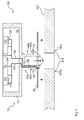
- FIGS. 1 and 2 show a first embodiment of a housing 10 according to the invention, in which a wide variety of components 100 are arranged.
- a housing interior 30 which is closed by a surrounding housing wall 20
- two switches 110 are formed here as electromechanical components.
- a sensor 130 and a lighting element 120 are provided for each switch 110.
- cables 150 are provided which run in the housing interior 30 to the individual components 100.
- the housing 10 is intended to be fastened to the body 200 of a vehicle.
- a passage opening is provided as a counter contact opening, which in this embodiment has mating contact surfaces 242 in the form of counter-adhesive surfaces 242b.
- FIG. 1 the mounting situation is shown.
- a compensation element 50 is used for an elastic tolerance compensation between the housing 10 and the body 200.
- the arrow in the middle or the two arrows for the compensation element 50 indicate the mounting direction.
- the housing 10 is in a position according to FIG. 2 in that the contact surfaces 42 of the housing 10 contact the mating contact surfaces 242 in an adhesive and thus fastening manner.
- the compensating element 50 is at least partially elastically deformed and in this way forms a sealing effect with the acting sealing force.
- the cables 150 are passed through a corresponding cable bushing 22 as part of the contact elements 40 and can now from the inside of the body 200, ie in FIG. 2 from below, be contacted electrically.
- FIG. 3 and 4 show an alternative embodiment of a housing according to the invention 10.
- components 100 in the form of switches 110, lighting elements 120 and sensors 130 in the housing interior 30 are arranged.
- an embodiment of the contact elements 40 is provided as latching elements 40a.
- the two contact surfaces 42 shown here are also designed as latching surfaces 42a.
- the mating contact surfaces 242 are formed as counter-locking surfaces 242a.
- the cables 150 extend along the cable gland 22 through the complete contact element 40 on the left side.
- an electrical contacting of these cables 150 from the inside of the body 200, ie from below according to FIG. 4 , respectively.
- FIG. 5 is a further embodiment of a housing 10 according to the invention shown from below.
- the component 100 has a surrounding or annular circumferential configuration of the compensating element 50 around the two contact elements 40, which are designed here as latching elements 40a. This makes it possible to achieve a circumferential seal with the already explained sealing function.
- FIGS. 6 and 7 show two different ways to provide a compensation element 50.
- multilayer materials are used.
- a foam 56 is provided between two adhesive surfaces 54 here.
- This foam 56 serves to provide the desired flexibility in order to allow elastic deformability under the action of a sealing force.
- the thickness 52 of the respective compensating element 50 is dimensioned so that during assembly according to FIGS. 1 and 2 or 3 and 4 an elastic compression takes place, so that the desired sealing force for a reduction of the thickness 52 is present.
Abstract
Die Erfindung betrifft ein Gehäuse (10) für wenigstens ein elektrisches Bauteil (100), insbesondere ein elektromechanisches Schaltbauteil, zur Anbringung in oder an einem Fahrzeug, aufweisend eine Gehäusewand (20), welche einen Gehäuseinnenraum (30) umgibt. Erfindungsgemäß ist vorgesehen, dass an der Gehäusewand (20) wenigstens ein nach Außen gerichtetes Kontaktelement (40) angeordnet ist mit wenigstens einer Kontaktfläche (42) zur befestigenden Kontaktierung mit einer Gegenkontaktfläche (242).The invention relates to a housing (10) for at least one electrical component (100), in particular an electromechanical switching component, for mounting in or on a vehicle, comprising a housing wall (20) surrounding a housing interior (30). According to the invention, at least one outwardly directed contact element (40) is arranged on the housing wall (20) with at least one contact surface (42) for fastening contact with a mating contact surface (242).
Description
Die vorliegende Erfindung betrifft ein Gehäuse für wenigstens ein elektrisches Bauteil, insbesondere ein elektromechanisches Bauteil, zur Anbringung in oder an einem Fahrzeug, sowie ein Schaltbauteil mit einem Gehäuse zur Anbringung an einem Fahrzeug und ein Verfahren für die Befestigung eines Schaltbauteils an der Karosserie eines Fahrzeugs.The present invention relates to a housing for at least one electrical component, in particular an electromechanical component, for mounting in or on a vehicle, as well as a switching component with a housing for attachment to a vehicle and a method for fastening a switching component to the body of a vehicle.
Es ist bekannt, dass in einem Fahrzeug Gehäuse befestigt werden sollen, welche elektronische Bauteile aufweisen. Bei den elektronischen Bauteilen handelt es sich dabei häufig um elektromechanische Schaltbauteile, also vom Insassen des Fahrzeugs bedienbare Schaltelemente. Diese Gehäuse sind häufig derart ausgebildet, dass sie auch widrigen Umweltbedingungen standhalten müssen. Neben einer Anordnung im Innenraum kommen dabei auch Anordnungen an der Außenseite der Karosserie, z. B. im Bereich der Türgriffe oder der Öffnungsmechanik für den Kofferraum in Frage.It is known that housing should be mounted in a vehicle, which have electronic components. The electronic components are often electromechanical switching components, ie switching elements which can be operated by the occupant of the vehicle. These housings are often designed so that they must withstand adverse environmental conditions. In addition to an arrangement in the interior are also arrangements on the outside of the body, z. B. in the field of door handles or the opening mechanism for the trunk in question.
Um die bekannten elektrischen Bauteile durch Gehäuse zu schützen, werden diese in bekannter Weise mit der Karosserie zur Befestigung verschraubt. Dies bringt diverse Nachteile mit sich. Zum einen ist durch die Notwendigkeit einer Lasche für die Verschraubung ein zusätzlicher Platzbedarf notwendig. Dies führt zu einem größeren Gehäuse und neben dem Platzverbrauch auch zu mehr Gewicht. Die Verwendung von Schrauben ist ebenfalls ein Faktor, welcher das Gewicht bekannter Gehäuselösungen vergrößert. Nicht zuletzt ist der Aufwand der Verschraubung selbst bei der Montage des Gehäuses an der Karosserie erhöht, und führt zu einem höheren Zeitaufwand mit damit einhergehenden höheren Kosten bei der Fertigung.In order to protect the known electrical components by housing, they are bolted in a known manner to the body for attachment. This brings with it several disadvantages. On the one hand, an additional space requirement is necessary due to the necessity of a tab for the screw connection. This leads to a larger housing and in addition to the space consumption and more weight. The use of screws is also a factor that increases the weight of known housing solutions. Last but not least, the expense of screwing is increased even when mounting the housing to the body, and leads to a higher expenditure of time with concomitant higher costs in manufacturing.
Es ist Aufgabe der vorliegenden Erfindung, die voranstehend beschriebenen Nachteile zumindest teilweise zu beheben. Insbesondere ist es Aufgabe der vorliegenden Erfindung, in kostengünstiger und einfacher Weise die Befestigung eines elektrischen Bauteils in einem Fahrzeug zu gewährleisten.It is an object of the present invention to at least partially overcome the disadvantages described above. In particular, it is an object of the present invention to ensure in a cost effective and simple manner the attachment of an electrical component in a vehicle.
Voranstehende Aufgabe wird gelöst durch ein Gehäuse mit den Merkmalen des Anspruchs 1, ein Schaltbauteil mit den Merkmalen des Anspruchs 10 sowie ein Verfahren mit den Merkmalen des Anspruchs 11. Weitere Merkmale und Details der Erfindung ergeben sich aus den Unteransprüchen, der Beschreibung und den Zeichnungen. Dabei gelten Merkmale und Details, die im Zusammenhang mit dem erfindungsgemäßen Gehäuse beschrieben sind, selbstverständlich auch im Zusammenhang mit dem erfindungsgemäßen Schaltbauteil sowie dem erfindungsgemäßen Verfahren und jeweils umgekehrt, sodass bzgl. der Offenbarung zu den einzelnen Erfindungsaspekten stets wechselseitig Bezug genommen wird bzw. werden kann.The above object is achieved by a housing with the features of claim 1, a switching device having the features of
Erfindungsgemäß ist ein Gehäuse für wenigstens ein elektrisches Bauteil, insbesondere ein elektromechanisches Schaltbauteil zur Anbringung in oder an einem Fahrzeug, vorgesehen. Das Gehäuse weist eine Gehäusewand auf, welche einen Gehäuseinnenraum umgibt. Das Gehäuse zeichnet sich erfindungsgemäß dadurch aus, dass an der Gehäusewand wenigstens ein nach außen gerichtetes Kontaktelement angeordnet ist mit wenigstens einer Kontaktfläche zur befestigenden Kontaktierung an einer Gegenkontaktfläche. Die Gegenkontaktfläche ist dabei vorzugsweise Teil der Karosserie des Fahrzeugs.According to the invention, a housing is provided for at least one electrical component, in particular an electromechanical switching component for mounting in or on a vehicle. The housing has a housing wall which surrounds a housing interior. The housing is characterized according to the invention in that on the housing wall at least one outwardly directed contact element is arranged with at least one contact surface for fastening contacting on a mating contact surface. The mating contact surface is preferably part of the body of the vehicle.
Ein erfindungsgemäßes Gehäuse dient also dazu, elektrische Bauteile bzw. insbesondere elektromechanische Schaltbauteile zu schützen. Dafür ist die Gehäusewand bzw. ein Teil der Gehäusewand vorzugsweise wasserundurchlässig ausgebildet. Auch kann das Gehäuse weitere Bauteile, insbesondere in Form von Dichtmitteln aufweisen, um das gesamte Gehäuse wasserdicht oder im Wesentlichen wasserdicht mit Bezug auf den Gehäuseinnenraum auszubilden. Dabei ist darauf hinzuweisen, dass für möglicherweise notwendige Druckausgleichssituationen selbstverständlich die Gehäusewand oder andere Bauteile des Gehäuses einen entsprechenden Druckausgleich, z. B. mit Hilfe einer Entlüftungsöffnung zulassen.An inventive housing thus serves to protect electrical components or in particular electromechanical switching components. For the housing wall or a part of the housing wall is preferably formed impermeable to water. The housing can also have further components, in particular in the form of sealing means, in order to form the entire housing in a watertight or substantially watertight manner with respect to the housing interior. It should be noted that for possibly necessary pressure equalization situations, of course, the housing wall or other components of the housing a corresponding pressure equalization, for. B. with the help of a vent.
Der Gehäuseinnenraum dient demnach als Aufnahmeraum für das elektrische Bauteil. Handelt es sich bei dem elektrischen Bauteil um ein elektromechanisches Schaltbauteil, so kann dies eine mechanische Betätigung in ein elektrisches Signal umwandeln. Dies ist z. B. für die Entriegelung und den Öffnungsvorgang in automatisierter Weise für die Heckklappe eines Fahrzeugs denkbar. So kann z. B. ein erfindungsgemäßes Gehäuse einen entsprechenden Kontaktschalter als mechanisches Schaltbauteil für das Öffnen der Heckklappe aufweisen. Das Gehäuse, welches in seinem Gehäuseinnenraum das wenigstens eine elektrische Bauteil aufweist, muss dementsprechend an der Karosserie an der gewünschten Position an der Heckklappe befestigt werden.The housing interior thus serves as a receiving space for the electrical component. If the electrical component is an electromechanical switching component, this can convert a mechanical actuation into an electrical signal. This is z. B. for unlocking and the opening process in an automated manner for the tailgate of a vehicle conceivable. So z. B. an inventive housing having a corresponding contact switch as a mechanical switching device for opening the tailgate. The housing, which has at least one electrical component in its housing interior, must accordingly be fastened to the bodywork at the desired position on the tailgate.
Bei dem voranstehend beschriebenen Beispiel wird der erfindungsgemäße Vorteil besonders klar deutlich. So muss nun nicht mehr in aufwendiger Weise eine Verschraubung des fertig gestellten Gehäuses, also des Gehäuses mit dem darin aufgenommen elektrischen Bauteil, mit der Karosserie erfolgen. Vielmehr kann durch das Vorhandensein des von der Gehäusewand nach außen gerichteten Kontaktelements eine einfache Kontaktierung der Kontaktfläche mit der Gegenkontaktfläche erfolgen. Damit entsteht die befestigende Kontaktierung ohne zusätzliche Mittel, insbesondere ohne zusätzliche Verschraubung.In the example described above, the advantage according to the invention becomes particularly clear. So now no longer has to be done in a complex way screwing the finished housing, so the housing with the electrical component housed therein, with the body. Rather, can be done by the presence of the housing wall outwardly directed contact element, a simple contacting of the contact surface with the mating contact surface. This creates the fastening contact without additional funds, in particular without additional screwing.
Unter einem Kontaktelement mit wenigstens einer Kontaktfläche ist dabei jedes Element zu verstehen, was eine befestigende Wirkung bei der Kontaktierung zwischen der Kontaktfläche und der Gegenkontaktfläche ermöglicht. Zwei bevorzugte Lösungen für ein Kontaktelement mit Kontaktflächen sind nachfolgend beschreiben. So kann das Kontaktelement insbesondere als Klebeelement mit wenigstens einer Klebefläche ausgebildet sein, sodass die befestigende Kontaktierung eine Verklebung mit der Gegenkontaktfläche darstellt. Auch eine Möglichkeit ist es, wenn das Kontaktelement als Rastelement ausgebildet ist, wobei dieses eine Rastfläche zur verrasteten befestigten Kontaktierung einer Gegenkontaktfläche in Form einer Gegenrastfläche ausbildet.Under a contact element with at least one contact surface is to understand each element, which allows a fastening effect in the contact between the contact surface and the mating contact surface. Two preferred solutions for a contact element with contact surfaces are described below. So can the contact element in particular be designed as an adhesive element with at least one adhesive surface, so that the fastening contacting represents a bond with the mating contact surface. It is also a possibility if the contact element is designed as a latching element, wherein this forms a latching surface for the latched fixed contacting a mating contact surface in the form of a counter-latching surface.
Die beiden voranstehenden Beispiele für Kontaktelemente sind eine nicht abschließende Liste, und dementsprechend nicht einschränkend für den Schutzbereich der vorliegenden Anmeldung. Wie aus diesen Beispielen deutlich wird, wird durch ein erfindungsgemäßes Gehäuse eine einfache, schnelle und damit vor allem kostengünstige Montage des Gehäuses an der Karosserie des Fahrzeugs möglich. Auch ist dieser Montagevorgang leichter und vor allem risikoärmer durchzuführen, als dies bei einer Verschraubung der Fall ist. Dementsprechend kann auch eine zusätzliche Öse für eine zusätzliche Schraube unterbleiben, sodass ein erfindungsgemäßes Gehäuse kleiner und vor allem auch leichter ausgebildet werden kann.The two preceding examples of contact elements are a non-exhaustive list, and accordingly not limiting to the scope of the present application. As is clear from these examples, by a housing according to the invention a simple, fast and thus above all cost-effective installation of the housing on the body of the vehicle possible. Also, this assembly process is easier and, above all, to carry out less risk than is the case with a screw. Accordingly, an additional eyelet for an additional screw can be omitted, so that an inventive housing smaller and above all can be made lighter.
Es kann von Vorteil sein, wenn bei einem erfindungsgemäßen Gehäuse das wenigstens eine Kontaktelement als Rastelement ausgebildet ist mit wenigstens einer Kontaktfläche in Form einer Rastfläche zur verrastenden Kontaktierung mit einer Gegenkontaktfläche in Form einer Gegenrastfläche. Ein Rastelement dient also dazu, durch ein elastisches Verformen aus einer Rastposition in eine Freigabeposition eine Bewegung des Gehäuses in seine Montageposition zuzulassen. Befindet sich das Gehäuse in der Montageposition wird durch elastische Rückstellkräfte innerhalb des Rastelements dieses aus seiner Freigabeposition wieder in seine Rastposition bewegt, sodass nun die Rastfläche mit der Gegenrastfläche an der Karosserie eine verrastende Kontaktierung ausbildet. Mit anderen Worten wird ein Gehäuse dieser Ausführungsform einfach, kostengünstig und vor allem schnell in eine entsprechende Rastöffnung der Karosserie eingedrückt und verrastet. Diese Lösung kann selbstverständlich mit Kontaktelementen anderer technischer Ausführungsformen kombiniert werden. Insbesondere ist eine Kombination mit einem Verkleben möglich, wie es nachfolgend beschrieben wird. Auch kann ein Kontaktelement zwei oder mehr Funktionalitäten aufweisen. So kann beispielsweise die Rastfläche des Rastelements gleichzeitig mit einem Kleber versehen sein und damit auch als Klebefläche in Form einer Kontaktfläche wirken.It may be advantageous if in a housing according to the invention the at least one contact element is designed as a latching element with at least one contact surface in the form of a latching surface for latching contacting with a mating contact surface in the form of a counter-latching surface. A latching element thus serves to allow a movement of the housing in its mounting position by an elastic deformation from a detent position to a release position. The housing is in the mounting position is moved by elastic restoring forces within the locking element of this from its release position back into its locking position, so that now the locking surface with the counter-locking surface on the body forms a latching contact. In other words, a housing of this embodiment is simple, inexpensive and above all pressed quickly into a corresponding detent opening of the body and locked. Of course, this solution can be combined with contact elements of other technical embodiments. In particular, a combination with a bonding is possible, as will be described below. Also, a contact element may have two or more functionalities. Thus, for example, the latching surface of the latching element can be provided simultaneously with an adhesive and thus also act as an adhesive surface in the form of a contact surface.
Erfindungsgemäß ist es weiter von Vorteil, wenn bei einem erfindungsgemäßen Gehäuse das wenigstens eine Kontaktelement als Klebeelement ausgebildet ist mit wenigstens einer Kontaktfläche in Form einer Klebefläche zur klebenden Kontaktierung mit einer Gegenkontaktfläche in Form einer Gegenklebefläche. Wie bereits im voranstehenden Absatz erläutert, ist dies eine weitere Möglichkeit die Kontaktierungen befestigender Weise zur Verfügung zu stellen. Auch die im voranstehenden Absatz beschriebene Kombinationsmöglichkeit verschiedener Elemente bzw. verschiedener Kontaktfunktionalitäten in einem Kontaktelement ist selbstverständlich möglich. Die Oberfläche der Klebefläche ist dabei vorzugsweise mit Klebstoff bearbeitet bzw. versehen. Dafür kann die Oberflächenstruktur vorbereitet sein, insbesondere aufgeraut, um eine verbesserte Klebewirkung zu erzielen. Auch kann die Klebefläche selbst den Klebstoff aufweisen, um z. B. über Druckaktivierung oder Hitzeaktivierung die Klebewirkung zu aktivieren.According to the invention it is also advantageous if, in a housing according to the invention, the at least one contact element is designed as an adhesive element with at least one contact surface in the form of an adhesive surface for adhesive contacting with a mating contact surface in the form of a counter-adhesive surface. As already explained in the preceding paragraph, this is another way to provide the contacting fixings way. The possibility of combining different elements or different contact functionalities in a contact element described in the preceding paragraph is of course possible. The surface of the adhesive surface is preferably processed or provided with adhesive. For this, the surface structure can be prepared, in particular roughened, in order to achieve an improved adhesive effect. Also, the adhesive surface itself may have the adhesive to z. B. on pressure activation or heat activation to activate the adhesive effect.
Ein weiterer Vorteil ist erzielbar, wenn bei einem erfindungsgemäßen Gehäuse an der Gehäusewand ein nach außen gerichtetes flexibles Ausgleichselement angeordnet ist, welches das wenigstens eine Kontaktelement insbesondere zumindest abschnittsweise umgibt. Ein flexibles Ausgleichselement ist dabei auf den Ausgleich in elastisch verformender Weise des eigenen Materials für geometrische Unterschiede zwischen der Gehäusewand und der anliegenden Karosserie ausgebildet. So wird es häufig vorkommen, dass durch Toleranzunterschiede die Karosserie bzw. die Gehäusewand des erfindungsgemäßen Gehäuses nicht plan aneinander liegen würden. Dies könnte möglicherweise zu einer Reduktion der Befestigungswirkung der Kontaktelemente führen. Um dies zu vermeiden, kann ein flexibles Ausgleichselement vorgesehen werden, welches durch flexible und damit elastische Verformung seines eigenen Materials solche Ungleichheiten und Toleranzen ausgleichen kann. Insbesondere ist ein solches flexibles Ausgleichselement auch als Dichtelement wirksam bzw. ausgebildet. Nicht zuletzt kann auf diese Weise eine Beschichtung des Karosseriebauteils, an welchem das Gehäuse befestigt wird, geschützt werden. Ist beispielsweise ein Lack oder eine anders geartete Schutzbeschichtung auf der Karosserie vorgesehen, so kann das flexible Ausgleichselement durch seine elastische Verformbarkeit einen Schutz zur Verfügung stellen. Das flexible Ausgleichselement kann z. B. in Form eines Ausgleichspads im Wesentlichen flächig ausgebildet sein. Insbesondere weist das flexible Ausgleichselement ein Kunststoffmaterial auf. Für die Montage ist das flexible Ausgleichselement insbesondere zumindest temporär an der Gehäusewand befestigt. Zum Beispiel kann eine einfache Verklebung vorgesehen sein, dass für die kontaktierende Befestigung die Anordnung des flexiblen Ausgleichselements mit hoher Wahrscheinlichkeit auch an der gewünschten Position verbleibt. Das Ausgleichselement kann dabei mit dem Kontaktelement vorzugsweise eine bauliche Einheit bilden. Insbesondere können Ausgleichselement und Kontaktelement integral miteinander, also einstückig bzw. monolithisch, ausgebildet sind.A further advantage can be achieved if, in a housing according to the invention, an outwardly directed flexible compensation element is arranged on the housing wall, which surrounds the at least one contact element, in particular at least in sections. A flexible compensation element is formed on the compensation in an elastically deforming manner of the own material for geometric differences between the housing wall and the adjacent body. Thus, it will often happen that due to tolerance differences, the body or the housing wall of the housing according to the invention would not lie flat against each other. This could possibly lead to a reduction of the fastening effect of the contact elements. To avoid this, a flexible compensation element can be provided, which can compensate for such inequalities and tolerances by flexible and thus elastic deformation of its own material. In particular, such a flexible compensation element is also effective or designed as a sealing element. Not least can be protected in this way a coating of the body component to which the housing is attached. For example, if a paint or a different type of protective coating provided on the body, the flexible compensation element can provide protection by its elastic deformability. The flexible compensation element can, for. B. in the form of a compensation pads be formed substantially flat. In particular, the flexible compensation element comprises a plastic material on. For assembly, the flexible compensation element is in particular attached at least temporarily to the housing wall. For example, a simple bond may be provided that for the contacting attachment, the arrangement of the flexible compensation element with high probability also remains at the desired position. The compensation element may preferably form a structural unit with the contact element. In particular, compensating element and contact element can be formed integrally with one another, that is to say in one piece or monolithically.
Es ist ebenfalls von Vorteil, wenn bei einem erfindungsgemäßen Gehäuse das Ausgleichselement eine Dicke aufweist, welche derart mit der Kontaktfläche korreliert, dass bei befestigender Kontaktierung der Gegenkontaktfläche durch die Kontaktfläche des Kontaktelements eine Dichtkraft, insbesondere in elastisch verformender Weise, auf das Ausgleichselement einwirkt. Mit anderen Worten bilden die geometrische Korrelation zwischen Gegenkontaktfläche und Kontaktfläche sowie der Dicke des Ausgleichselementes eine finale Montagesituation, welche vorzugsweise zu einer elastisch verformten Reduktion der Dicke des Ausgleichselements in der Montagesituation führt. Mit anderen Worten wirkt in der montierten Situation eine Dichtkraft auf das Ausgleichselement, sodass nun eine Abdichtung eines entsprechenden Montagelochs bzw. einer entsprechenden Montageöffnung in der Karosserie gegen das Eindringen von Wasser vorliegt. Dies führt zu einer Reduktion von Korrosionsgefahr von diesem Karosseriebereich.It is also advantageous if, in a housing according to the invention, the compensation element has a thickness which correlates with the contact surface in such a way that, when the contacting contact surface is fixed by the contact surface of the contact element, a sealing force, in particular in an elastically deforming manner, acts on the compensation element. In other words, the geometric correlation between mating contact surface and contact surface and the thickness of the compensating element form a final assembly situation, which preferably leads to an elastically deformed reduction of the thickness of the compensating element in the mounting situation. In other words, acts in the assembled situation, a sealing force on the compensating element, so now there is a seal of a corresponding mounting hole or a corresponding mounting hole in the body against the ingress of water. This leads to a reduction of the risk of corrosion of this body area.
Ein weiterer Vorteil kann erzielt werden, wenn bei einem erfindungsgemäßen Gehäuse das Ausgleichselement ringförmig ausgebildet ist und das wenigstens eine Kontaktelement umgibt. Das Umgeben kann dabei unterschiedlichste Geometrien aufweisen. Insbesondere kann das Ausgleichselement rund, eckig oder mit einer anderen ringförmigen Form das Kontaktelement umgeben. Bevorzugt werden alle Kontaktelemente einzeln bzw. alle Kontaktelemente gemeinsam vollständig von einem oder mehreren Ausgleichselementen umgeben. Dies führt sozusagen zu einer Abdichtung um alle Kontaktelemente herum. Da üblicherweise für jedes Kontaktelement bzw. für alle Kontaktelemente gemeinsam eine entsprechende Gegenkontaktöffnung innerhalb der Karosserie vorgesehen ist, wirkt eine derartige Ausführungsform abdichtend auch gegen diese Gegenkontaktöffnung der Karosserie.A further advantage can be achieved if in a housing according to the invention, the compensation element is annular and surrounds the at least one contact element. The surrounding can have very different geometries. In particular, the compensating element can surround the contact element in a round, angular or other annular shape. Preferably, all contact elements are individually or all contact elements together completely surrounded by one or more compensation elements. This leads, so to speak, to a seal around all contact elements. Since usually for each contact element or for all contact elements together a corresponding mating contact opening is provided within the body, such an embodiment acts sealingly against this mating contact opening of the body.
Vorteilhaft ist es weiter, wenn bei einem erfindungsgemäßen Gehäuse das Ausgleichselement wenigstens eine der folgenden Ausbildungen aufweist:
- Schaumstoff, insbesondere wasserfester Schaumstoff
- Klebeband, insbesondere mit einer Schaumstoffzwischenschicht
- Silikonelement
- Gummielement
- Foam, in particular water-resistant foam
- Adhesive tape, in particular with a foam intermediate layer
- silicone element
- rubber element
Bei der voranstehenden Aufzählung handelt es sich um eine nicht abschließende Liste. Selbstverständlich können auch unterschiedliche Ausgleichselemente miteinander kombiniert werden, um ein oder mehrere erfindungsgemäße Ausgleichselemente auszubilden. Dabei können auch unterschiedliche Formen der Ausgleichselemente kombiniert werden. Ist das Ausgleichselement als Klebeband ausgebildet, so kann dieses einseitig oder auch zweiseitig klebend ausgebildet sein. Insbesondere ist in einem solchen Fall das Ausgleichselement als bauliche Einheit mit dem Kontaktelement ausgebildet, sodass die Klebefunktion gleichzeitig die befestigende Kontaktierungsfunktion ausbildet.The list above is a non-exhaustive list. Of course, different compensation elements can be combined with each other to form one or more compensation elements according to the invention. In this case, different forms of compensating elements can be combined. If the compensating element is designed as an adhesive tape, it can be designed to be adhesive on one or two sides. In particular, in such a case, the compensation element is designed as a structural unit with the contact element, so that the adhesive function simultaneously forms the fastening contacting function.
Vorteilhaft ist es weiter, wenn bei einem erfindungsgemäßen Gehäuse das Gehäuse wenigstens eines der folgenden Bauteile in seinem Gehäuseinnenraum aufweist:
- Taster
- Schalter
- Sensor, insbesondere kapazitiver und/oder optischer Sensor
- Beleuchtungselement
- button
- switch
- Sensor, in particular capacitive and / or optical sensor
- lighting element
Bei der voranstehenden Aufzählung handelt es sich um eine nicht abschließende Liste. Als Beleuchtungselement kann z. B. eine LED oder ein externer Lichtleiter eingesetzt werden, um eine Beleuchtung des Gehäuseinnenraums bzw. nach außen durch teiltransparente oder transparente Ausbildung der Gehäusewand vorzunehmen. Sensoren sind in der Lage die Annäherung von Personen oder Körperteilen von Personen kapazitiv oder optisch wahrzunehmen. Der Schalter selbst ist in der Lage eine Betätigung durchzuführen und dabei insbesondere ein elektrisches Signal auszulösen bzw. zu verwenden. Beispielsweise kann eine Kopplung des Sensors mit dem Beleuchtungselement vorliegen, sodass bei Erkennung der Annäherung eines Körperteils des Benutzers oder des gesamten Benutzers, das Beleuchtungselement das Gehäuse von innen heraus beleuchtet. Dies führt zu einer erleichterten Auffindbarkeit, insbesondere bei kleinen oder versteckt angeordneten Gehäusen an der Karosserie.The list above is a non-exhaustive list. As a lighting element can, for. B. an LED or an external light guide can be used to make an illumination of the housing interior or to the outside by partially transparent or transparent design of the housing wall. Sensors are able to perceive the approach of persons or body parts of persons capacitively or optically. The switch itself is able to perform an operation and in particular to trigger or use an electrical signal. For example, there may be a coupling of the sensor to the lighting element, so that upon detection the approach of a body part of the user or the entire user, the lighting element illuminates the housing from the inside out. This leads to a facilitated findability, especially in small or hidden arranged housings on the body.
Vorteilhaft ist es darüber hinaus, wenn bei einem erfindungsgemäßen Gehäuse die Gehäusewand wenigstens eine Kabeldurchführung aufweist, welche eine Führung eines hindurchgeführten Kabels zur Vermeidung von Knickstellen und/oder Scheuerstellen ausbildet. Dabei ist die Kabelführung insbesondere wenigstens abschnittsweise durch das wenigstens eine Kontaktelement ausgebildet. Die Kabeldurchführung dient also dazu eine Stromversorgung bzw. eine Signalkommunikation zwischen dem Gehäuseinnenraum und einer externen Versorgungseinheit bzw. einer externen Kontrolleinheit zu ermöglichen. Kabel, könnten dabei als Signalkabel, als Kommunikationskabel und/oder auch als Energieversorgungskabel ausgebildet sein. Dabei dient die Kabeldurchführung dazu, insbesondere eine Wasserdichtigkeit des Gehäuseinnenraums zu gewährleisten. Weiter kann durch die Kabeldurchführung wenigstens abschnittsweise durch das Kontaktelement eine Führung der Kabel hinter das Karosserieelement zulassen, an welchem das Gehäuse befestigt werden soll. Bevorzugt ist es, wenn die einzelnen Kabel eine Kontaktfläche im elektrischen Sinn an dem jeweiligen Kontaktelement aufweisen, sodass in entsprechender Weise zur kontaktierenden Befestigung auch eine automatische oder im Wesentlichen automatische elektrische Kontaktierung zwischen der elektrischen Kontaktfläche und einer elektrischen Gegenkontaktfläche stattfinden kann.In addition, it is advantageous if, in a housing according to the invention, the housing wall has at least one cable bushing which forms a guide of a cable passed through to avoid kinks and / or chafing. In this case, the cable guide is in particular at least partially formed by the at least one contact element. The cable feedthrough thus serves to enable a power supply or a signal communication between the housing interior and an external supply unit or an external control unit. Cable, could be designed as a signal cable, as a communication cable and / or as a power supply cable. In this case, the cable bushing serves in particular to ensure a water-tightness of the housing interior. Further, by the cable bushing at least in sections by the contact element allow a guide of the cable behind the body member to which the housing is to be attached. It is preferable if the individual cables have a contact surface in the electrical sense at the respective contact element, so that an automatic or substantially automatic electrical contact between the electrical contact surface and an electrical mating contact surface can take place in a corresponding manner to the contacting attachment.
Ebenfalls Gegenstand der vorliegenden Erfindung ist ein Schaltbauteil mit einem Gehäuse, aufweisend die Merkmale der vorliegenden Erfindung, wobei im Gehäuseinnenraum wenigstens ein elektrisches Bauteil angeordnet ist. Damit bringt ein erfindungsgemäßes Schaltbauteil die gleichen Vorteile mit sich, wie sie ausführlich mit Bezug auf ein erfindungsgemäßes Gehäuse erläutert worden sind. Insbesondere ist das Schaltbauteil einzusetzen für eine Befestigung an der Karosserie des Fahrzeugs, z. B. im Innenraum oder an der Außenseite.Likewise provided by the present invention is a switching component having a housing, comprising the features of the present invention, wherein at least one electrical component is arranged in the housing interior. Thus, a switching component according to the invention brings the same advantages as have been explained in detail with reference to a housing according to the invention. In particular, the switching component is to be used for attachment to the body of the vehicle, for. B. in the interior or on the outside.
Ein weiterer Gegenstand der vorliegenden Erfindung ist ein Verfahren für die Befestigung eines Schaltbauteils, insbesondere gemäß der vorliegenden Erfindung, an der Karosserie eines Fahrzeugs, aufweisend die folgenden Schritte:
- Kontaktieren einer Gegenkontaktfläche mit wenigstens einer Kontaktfläche eines Kontaktelements des Gehäuses, des Schaltbauteils und der Ausbildung einer Befestigung.
- Contacting a mating contact surface with at least one contact surface of a contact element of the housing, the switching component and the formation of a fastening.
Ein erfindungsgemäßes Verfahren bringt dementsprechend die gleichen Vorteile mit sich, wie sie ausführlich mit Bezug auf ein erfindungsgemäßes Gehäuse erläutert worden sind. Die entsprechende Öffnung für die Aufnahme der Kontaktelemente des Gehäuses kann auch als Gegenkontaktöffnung bezeichnet werden und ist vorzugsweise Teil einer Kabeldurchführung in den Innenraum hinter der Karosserie.Accordingly, a method according to the invention entails the same advantages as have been explained in detail with reference to a housing according to the invention. The corresponding opening for receiving the contact elements of the housing may also be referred to as mating contact opening and is preferably part of a cable duct in the interior behind the body.
Ein weiterer Gegenstand der vorliegenden Erfindung ist ein Fahrzeug, insbesondere ein Kraftfahrzeug, aufweisend wenigstens ein erfindungsgemäßes Schaltbauteil.Another object of the present invention is a vehicle, in particular a motor vehicle, comprising at least one inventive switching component.
Weitere Vorteile, Merkmale und Einzelheiten der Erfindung ergeben sich aus der nachfolgenden Beschreibung, in der unter Bezugnahme auf die Zeichnungen Ausführungsbeispiele der Erfindung im Einzelnen beschrieben sind. Dabei können die in den Ansprüchen und in der Beschreibung erwähnten Merkmale jeweils einzeln für sich oder in beliebiger Kombination erfindungswesentlich sein. Es zeigen schematisch:
- Fig. 1
- eine erste Ausführungsform eines erfindungsgemäßen Schaltbauteils bei der Montage,
- Fig. 2
- die Ausführungsform der
Figur 1 nach der Montage, - Fig. 3
- eine weitere Ausführungsform eines erfindungsgemäßen Gehäuses bei der Montage,
- Fig. 4
- die Ausführungsform der
Figur 3 nach der Montage, - Fig. 5
- eine weitere Ausführungsform eines erfindungsgemäßen Gehäuses,
- Fig. 6
- eine Ausführungsform eines Ausgleichselements und
- Fig. 7
- eine weitere Ausführungsform eines Ausgleichselements.
- Fig. 1
- a first embodiment of a switching device according to the invention during assembly,
- Fig. 2
- the embodiment of the
FIG. 1 after assembly, - Fig. 3
- a further embodiment of a housing according to the invention during assembly,
- Fig. 4
- the embodiment of the
FIG. 3 after assembly, - Fig. 5
- a further embodiment of a housing according to the invention,
- Fig. 6
- an embodiment of a compensating element and
- Fig. 7
- a further embodiment of a compensating element.
Die
Das Gehäuse 10 soll an der Karosserie 200 eines Fahrzeugs befestigt werden. Hierfür ist eine Durchgangsöffnung als Gegenkontaktöffnung vorgesehen, welche bei dieser Ausführung Gegenkontaktflächen 242 in Form von Gegenklebeflächen 242b aufweist.The
In
In
Die
Die voranstehende Erläuterung der Ausführungsformen beschreibt die vorliegende Erfindung ausschließlich im Rahmen von Beispielen. Selbstverständlich können einzelne Merkmale, sofern technisch sinnvoll, frei miteinander kombiniert werden, ohne den Rahmen der vorliegenden Erfindung zu verlassen.The above explanation of the embodiments describes the present invention solely by way of example. Of course, individual characteristics, if technically reasonable, freely combined with one another, without departing from the scope of the present invention.
- 1010
- Gehäusecasing
- 2020
- Gehäusewandhousing wall
- 2222
- KabeldurchführungGrommet
- 3030
- GehäuseinnenraumHousing interior
- 4040
- Kontaktelementcontact element
- 40a40a
- Rastelementlocking element
- 40b40b
- Klebeelementadhesive element
- 4242
- Kontaktflächecontact area
- 42a42a
- RastflächeRest area
- 42b42b
- Klebeflächeadhesive surface
- 5050
- Ausgleichselementcompensation element
- 5252
- Dickethickness
- 5454
- Klebeflächeadhesive surface
- 5656
- Schaumstofffoam
- 100100
- Bauteilcomponent
- 110110
- Schalterswitch
- 120120
- Beleuchtungselementlighting element
- 130130
- Sensorsensor
- 150150
- Kabelelectric wire
- 200200
- Karosseriebody
- 242242
- GegenkontaktflächeAgainst the contact surface
- 242a242a
- GegenrastflächeCounter-locking surface
- 242b242b
- GegenklebeflächeAgainst adhesive surface
Claims (11)
dadurch gekennzeichnet,
dass an der Gehäusewand (20) wenigstens ein nach Außen gerichtetes Kontaktelement (40) angeordnet ist mit wenigstens einer Kontaktfläche (42) zur befestigenden Kontaktierung mit einer Gegenkontaktfläche (242).Housing (10) for at least one electrical component (100), in particular an electromechanical switching component, for mounting in or on a vehicle, comprising a housing wall (20) which surrounds a housing interior (30),
characterized,
in that at least one outwardly directed contact element (40) is arranged on the housing wall (20) with at least one contact surface (42) for fastening contact with a mating contact surface (242).
dadurch gekennzeichnet,
dass das wenigstens eine Kontaktelement (40) als Rastelement (40a) ausgebildet ist mit wenigstens einer Kontaktfläche (42) in Form einer Rastfläche (42a) zur verrastenden Kontaktierung mit einer Gegenkontaktfläche (242) in Form einer Gegenrastfläche (242a).Housing (10) according to claim 1,
characterized,
in that the at least one contact element (40) is designed as a latching element (40a) with at least one contact surface (42) in the form of a latching surface (42a) for latching contacting with a mating contact surface (242) in the form of a mating latching surface (242a).
dadurch gekennzeichnet,
dass das wenigstens eine Kontaktelement (40) als Klebeelement (40b) ausgebildet ist mit wenigstens einer Kontaktfläche (42) in Form einer Klebefläche (42b) zur klebenden Kontaktierung mit einer Gegenkontaktfläche (242) in Form einer Gegenklebefläche (242b).Housing (10) according to one of the preceding claims,
characterized,
in that the at least one contact element (40) is designed as an adhesive element (40b) with at least one contact surface (42) in the form of an adhesive surface (42b) for adhesive contacting with a mating contact surface (242) in the form of a counter-adhesive surface (242b).
dadurch gekennzeichnet,
dass an der Gehäusewand (20) ein nach Außen gerichtetes flexibles Ausgleichselement (50) angeordnet ist, welches das wenigstens eine Kontaktelement (40) insbesondere zumindest abschnittsweise umgibt.Housing (10) according to one of the preceding claims,
characterized,
in that on the housing wall (20) an outwardly directed flexible compensation element (50) is arranged, which surrounds the at least one contact element (40) in particular at least in sections.
dadurch gekennzeichnet,
dass das Ausgleichselement (50) eine Dicke (52) aufweist, welche derart mit der Kontaktfläche (42) korreliert, dass bei befestigender Kontaktierung der Gegenkontaktfläche (242) durch die Kontaktfläche (42) des Kontaktelements (40) eine Dichtkraft, insbesondere in elastisch verformender Weise, auf das Ausgleichselement (50) einwirkt.Housing (10) according to claim 4,
characterized,
in that the compensating element (50) has a thickness (52) which correlates with the contact surface (42) such that when the contacting surface (242) is in contact with the contact surface (42) of the contact element (40) a sealing force, in particular in elastically deforming Way, acting on the compensation element (50).
dadurch gekennzeichnet,
dass das Ausgleichselement (50) ringförmig ausgebildet ist und das wenigstens eine Kontaktelement (40) umgibt.Housing (10) according to one of claims 4 or 5,
characterized,
that the compensation element (50) is annular and surrounds the at least one contact element (40).
dadurch gekennzeichnet,
dass das Ausgleichselement (50) wenigstens eine der folgenden Ausbildungen aufweist:
characterized,
that the compensating element (50) comprises one of the following embodiments, at least:
dadurch gekennzeichnet,
dass das Gehäuse (10) wenigstens eines der folgenden Bauteile (100) in seinem Gehäuseinnenraum (30) aufweist:
characterized,
that the housing (10) has at least one of the following components (100) in its housing interior (30):
dadurch gekennzeichnet,
dass die Gehäusewand (20) wenigstens eine Kabeldurchführung (22) aufweist, welche eine Führung eines hindurchgeführten Kabels (150) zur Vermeidung von Knickstellen und/oder Scheuerstellen ausbildet, wobei die Kabelführung (22) insbesondere wenigstens abschnittsweise durch das wenigstens eine Kontaktelement (40) ausgebildet ist.Housing (10) according to one of the preceding claims,
characterized,
in that the housing wall (20) has at least one cable bushing (22) which forms a guide of a cable (150) passed through to avoid kinks and / or chafing, wherein the cable guide (22) in particular at least in sections by the at least one contact element (40). is trained.
Applications Claiming Priority (1)
| Application Number | Priority Date | Filing Date | Title |
|---|---|---|---|
| DE102013113200.6A DE102013113200A1 (en) | 2013-11-28 | 2013-11-28 | Housing for at least one electrical component |
Publications (2)
| Publication Number | Publication Date |
|---|---|
| EP2878494A1 true EP2878494A1 (en) | 2015-06-03 |
| EP2878494B1 EP2878494B1 (en) | 2019-03-27 |
Family
ID=52020959
Family Applications (1)
| Application Number | Title | Priority Date | Filing Date |
|---|---|---|---|
| EP14194762.2A Not-in-force EP2878494B1 (en) | 2013-11-28 | 2014-11-25 | Housing for at least one electrical component |
Country Status (3)
| Country | Link |
|---|---|
| EP (1) | EP2878494B1 (en) |
| CN (1) | CN104682605A (en) |
| DE (1) | DE102013113200A1 (en) |
Cited By (2)
| Publication number | Priority date | Publication date | Assignee | Title |
|---|---|---|---|---|
| CN105864586A (en) * | 2016-04-18 | 2016-08-17 | 杭州新罗美电子科技有限公司 | Fastening mechanism of portable LED displayer equipment and use method of fastening mechanism |
| EP3305610A1 (en) * | 2016-10-10 | 2018-04-11 | WABCO Europe BVBA | Electronic control unit for a vehicle, in particular commercial vehicle |
Citations (7)
| Publication number | Priority date | Publication date | Assignee | Title |
|---|---|---|---|---|
| DE3310477A1 (en) * | 1982-07-17 | 1984-01-19 | Robert Bosch Gmbh, 7000 Stuttgart | Electrical apparatus, especially a switching and control apparatus for motor vehicles |
| DE10339159A1 (en) * | 2002-10-04 | 2004-05-13 | Brose Fahrzeugteile Gmbh & Co. Kommanditgesellschaft, Coburg | Controller for one or more motor vehicle door functions has first connection unit(s) in dry volume in vehicle door and second connection unit in wet volume in vehicle door for connecting to electronics |
| EP1814764A1 (en) * | 2004-11-26 | 2007-08-08 | Siemens Aktiengesellschaft | Electronic device |
| WO2012010152A2 (en) * | 2010-06-25 | 2012-01-26 | Continental Automotive Gmbh | Electrical assembly for a motor vehicle that is suitable for contacting with a connector |
| WO2012031808A1 (en) * | 2010-09-10 | 2012-03-15 | Robert Bosch Gmbh | Connection system and accommodation unit for a control device |
| WO2013056956A1 (en) * | 2011-10-18 | 2013-04-25 | Robert Bosch Gmbh | Control unit for a motor vehicle having a connector housing |
| EP2623378A1 (en) * | 2012-02-03 | 2013-08-07 | Delphi Technologies, Inc. | Plug-in vehicle security system with a wireless relay |
Family Cites Families (1)
| Publication number | Priority date | Publication date | Assignee | Title |
|---|---|---|---|---|
| DE102011057193A1 (en) * | 2011-12-30 | 2013-07-04 | Huf Hülsbeck & Fürst Gmbh & Co. Kg | Housing for receiving an electronics unit |
-
2013
- 2013-11-28 DE DE102013113200.6A patent/DE102013113200A1/en not_active Withdrawn
-
2014
- 2014-11-25 EP EP14194762.2A patent/EP2878494B1/en not_active Not-in-force
- 2014-11-28 CN CN201410707442.XA patent/CN104682605A/en active Pending
Patent Citations (7)
| Publication number | Priority date | Publication date | Assignee | Title |
|---|---|---|---|---|
| DE3310477A1 (en) * | 1982-07-17 | 1984-01-19 | Robert Bosch Gmbh, 7000 Stuttgart | Electrical apparatus, especially a switching and control apparatus for motor vehicles |
| DE10339159A1 (en) * | 2002-10-04 | 2004-05-13 | Brose Fahrzeugteile Gmbh & Co. Kommanditgesellschaft, Coburg | Controller for one or more motor vehicle door functions has first connection unit(s) in dry volume in vehicle door and second connection unit in wet volume in vehicle door for connecting to electronics |
| EP1814764A1 (en) * | 2004-11-26 | 2007-08-08 | Siemens Aktiengesellschaft | Electronic device |
| WO2012010152A2 (en) * | 2010-06-25 | 2012-01-26 | Continental Automotive Gmbh | Electrical assembly for a motor vehicle that is suitable for contacting with a connector |
| WO2012031808A1 (en) * | 2010-09-10 | 2012-03-15 | Robert Bosch Gmbh | Connection system and accommodation unit for a control device |
| WO2013056956A1 (en) * | 2011-10-18 | 2013-04-25 | Robert Bosch Gmbh | Control unit for a motor vehicle having a connector housing |
| EP2623378A1 (en) * | 2012-02-03 | 2013-08-07 | Delphi Technologies, Inc. | Plug-in vehicle security system with a wireless relay |
Cited By (4)
| Publication number | Priority date | Publication date | Assignee | Title |
|---|---|---|---|---|
| CN105864586A (en) * | 2016-04-18 | 2016-08-17 | 杭州新罗美电子科技有限公司 | Fastening mechanism of portable LED displayer equipment and use method of fastening mechanism |
| EP3305610A1 (en) * | 2016-10-10 | 2018-04-11 | WABCO Europe BVBA | Electronic control unit for a vehicle, in particular commercial vehicle |
| WO2018068878A1 (en) * | 2016-10-10 | 2018-04-19 | Wabco Europe Bvba | Electronic control unit for a vehicle, in particular commercial vehicle |
| US11160177B2 (en) | 2016-10-10 | 2021-10-26 | Wabco Europe Bvba | Electronic control unit for a vehicle, in particular commercial vehicle |
Also Published As
| Publication number | Publication date |
|---|---|
| DE102013113200A1 (en) | 2015-05-28 |
| CN104682605A (en) | 2015-06-03 |
| EP2878494B1 (en) | 2019-03-27 |
Similar Documents
| Publication | Publication Date | Title |
|---|---|---|
| EP1181172B1 (en) | Steering wheel | |
| DE102010020961A1 (en) | Method and fastening device for fastening an assembly in an opening of a wall of a vehicle | |
| WO2016188694A1 (en) | Door handle system for a motor vehicle door | |
| DE3536142A1 (en) | Multipole electrical connection, which is constructed as a plug connection, between two components which are connected to one another in an articulated manner, especially between the bodywork and side door of motor vehicles | |
| DE102012005101A1 (en) | Electronic and / or gearbox housing | |
| DE102013206889B4 (en) | Actuating unit for a motor vehicle lock and Bowden cable | |
| WO2021043666A1 (en) | Actuation device with movable switch element, vehicle, and actuation method | |
| DE112014001079T5 (en) | wire harness | |
| DE102005053014A1 (en) | Pressure sensor housing and method for its manufacture | |
| EP2878494B1 (en) | Housing for at least one electrical component | |
| EP3309967B1 (en) | Capacitive switching device | |
| DE102010025689A1 (en) | Drive unit for a windshield wiper device in a vehicle and housing for a drive unit | |
| DE102005033621A1 (en) | Device with a grommet for a line transition between relatively movable vehicle parts | |
| DE102016109933A1 (en) | Outside door handle for a vehicle | |
| DE102016111602A1 (en) | Handle for a movable component of a motor vehicle | |
| DE102005038050A1 (en) | Drive unit for motor vehicles operates with an electric motor for window-winders or windscreen wiper devices along with a motor casing linked to a gear casing | |
| DE102016116743A1 (en) | Fiber reinforced housing member for receiving an electrical component, housing and manufacturing method equipped therewith | |
| DE102010033385A1 (en) | Hold request button for arrangement on handrails in vehicles | |
| DE102014107428A1 (en) | Door handle for a motor vehicle | |
| DE102018111007A1 (en) | Handle body for a door handle | |
| DE102006055100A1 (en) | Door handle for motor vehicle, has base and screen forming space for accommodation of support for electronic component part, and self-supporting connection provided between support and screen, where screen and base form clip connection | |
| EP2995507B1 (en) | Method for mounting an assembly between coach and door of a motor vehicle | |
| DE102015206481A1 (en) | Electronic control unit | |
| DE102019205270A1 (en) | Sensor device and torque measuring device of a motor vehicle steering system with such a sensor device | |
| DE102014119478A1 (en) | Electrical component for a closure element of a motor vehicle |
Legal Events
| Date | Code | Title | Description |
|---|---|---|---|
| PUAI | Public reference made under article 153(3) epc to a published international application that has entered the european phase |
Free format text: ORIGINAL CODE: 0009012 |
|
| 17P | Request for examination filed |
Effective date: 20141125 |
|
| AK | Designated contracting states |
Kind code of ref document: A1 Designated state(s): AL AT BE BG CH CY CZ DE DK EE ES FI FR GB GR HR HU IE IS IT LI LT LU LV MC MK MT NL NO PL PT RO RS SE SI SK SM TR |
|
| AX | Request for extension of the european patent |
Extension state: BA ME |
|
| R17P | Request for examination filed (corrected) |
Effective date: 20151203 |
|
| RBV | Designated contracting states (corrected) |
Designated state(s): AL AT BE BG CH CY CZ DE DK EE ES FI FR GB GR HR HU IE IS IT LI LT LU LV MC MK MT NL NO PL PT RO RS SE SI SK SM TR |
|
| STAA | Information on the status of an ep patent application or granted ep patent |
Free format text: STATUS: EXAMINATION IS IN PROGRESS |
|
| 17Q | First examination report despatched |
Effective date: 20161114 |
|
| GRAP | Despatch of communication of intention to grant a patent |
Free format text: ORIGINAL CODE: EPIDOSNIGR1 |
|
| STAA | Information on the status of an ep patent application or granted ep patent |
Free format text: STATUS: GRANT OF PATENT IS INTENDED |
|
| INTG | Intention to grant announced |
Effective date: 20181016 |
|
| GRAS | Grant fee paid |
Free format text: ORIGINAL CODE: EPIDOSNIGR3 |
|
| GRAA | (expected) grant |
Free format text: ORIGINAL CODE: 0009210 |
|
| STAA | Information on the status of an ep patent application or granted ep patent |
Free format text: STATUS: THE PATENT HAS BEEN GRANTED |
|
| AK | Designated contracting states |
Kind code of ref document: B1 Designated state(s): AL AT BE BG CH CY CZ DE DK EE ES FI FR GB GR HR HU IE IS IT LI LT LU LV MC MK MT NL NO PL PT RO RS SE SI SK SM TR |
|
| REG | Reference to a national code |
Ref country code: GB Ref legal event code: FG4D Free format text: NOT ENGLISH |
|
| REG | Reference to a national code |
Ref country code: CH Ref legal event code: EP |
|
| REG | Reference to a national code |
Ref country code: AT Ref legal event code: REF Ref document number: 1112663 Country of ref document: AT Kind code of ref document: T Effective date: 20190415 |
|
| REG | Reference to a national code |
Ref country code: IE Ref legal event code: FG4D Free format text: LANGUAGE OF EP DOCUMENT: GERMAN |
|
| REG | Reference to a national code |
Ref country code: DE Ref legal event code: R096 Ref document number: 502014011225 Country of ref document: DE |
|
| PG25 | Lapsed in a contracting state [announced via postgrant information from national office to epo] |
Ref country code: SE Free format text: LAPSE BECAUSE OF FAILURE TO SUBMIT A TRANSLATION OF THE DESCRIPTION OR TO PAY THE FEE WITHIN THE PRESCRIBED TIME-LIMIT Effective date: 20190327 Ref country code: LT Free format text: LAPSE BECAUSE OF FAILURE TO SUBMIT A TRANSLATION OF THE DESCRIPTION OR TO PAY THE FEE WITHIN THE PRESCRIBED TIME-LIMIT Effective date: 20190327 Ref country code: NO Free format text: LAPSE BECAUSE OF FAILURE TO SUBMIT A TRANSLATION OF THE DESCRIPTION OR TO PAY THE FEE WITHIN THE PRESCRIBED TIME-LIMIT Effective date: 20190627 Ref country code: FI Free format text: LAPSE BECAUSE OF FAILURE TO SUBMIT A TRANSLATION OF THE DESCRIPTION OR TO PAY THE FEE WITHIN THE PRESCRIBED TIME-LIMIT Effective date: 20190327 |
|
| REG | Reference to a national code |
Ref country code: NL Ref legal event code: MP Effective date: 20190327 |
|
| PG25 | Lapsed in a contracting state [announced via postgrant information from national office to epo] |
Ref country code: BG Free format text: LAPSE BECAUSE OF FAILURE TO SUBMIT A TRANSLATION OF THE DESCRIPTION OR TO PAY THE FEE WITHIN THE PRESCRIBED TIME-LIMIT Effective date: 20190627 Ref country code: RS Free format text: LAPSE BECAUSE OF FAILURE TO SUBMIT A TRANSLATION OF THE DESCRIPTION OR TO PAY THE FEE WITHIN THE PRESCRIBED TIME-LIMIT Effective date: 20190327 Ref country code: LV Free format text: LAPSE BECAUSE OF FAILURE TO SUBMIT A TRANSLATION OF THE DESCRIPTION OR TO PAY THE FEE WITHIN THE PRESCRIBED TIME-LIMIT Effective date: 20190327 Ref country code: NL Free format text: LAPSE BECAUSE OF FAILURE TO SUBMIT A TRANSLATION OF THE DESCRIPTION OR TO PAY THE FEE WITHIN THE PRESCRIBED TIME-LIMIT Effective date: 20190327 Ref country code: GR Free format text: LAPSE BECAUSE OF FAILURE TO SUBMIT A TRANSLATION OF THE DESCRIPTION OR TO PAY THE FEE WITHIN THE PRESCRIBED TIME-LIMIT Effective date: 20190628 Ref country code: HR Free format text: LAPSE BECAUSE OF FAILURE TO SUBMIT A TRANSLATION OF THE DESCRIPTION OR TO PAY THE FEE WITHIN THE PRESCRIBED TIME-LIMIT Effective date: 20190327 |
|
| PG25 | Lapsed in a contracting state [announced via postgrant information from national office to epo] |
Ref country code: IT Free format text: LAPSE BECAUSE OF FAILURE TO SUBMIT A TRANSLATION OF THE DESCRIPTION OR TO PAY THE FEE WITHIN THE PRESCRIBED TIME-LIMIT Effective date: 20190327 Ref country code: SK Free format text: LAPSE BECAUSE OF FAILURE TO SUBMIT A TRANSLATION OF THE DESCRIPTION OR TO PAY THE FEE WITHIN THE PRESCRIBED TIME-LIMIT Effective date: 20190327 Ref country code: AL Free format text: LAPSE BECAUSE OF FAILURE TO SUBMIT A TRANSLATION OF THE DESCRIPTION OR TO PAY THE FEE WITHIN THE PRESCRIBED TIME-LIMIT Effective date: 20190327 Ref country code: PT Free format text: LAPSE BECAUSE OF FAILURE TO SUBMIT A TRANSLATION OF THE DESCRIPTION OR TO PAY THE FEE WITHIN THE PRESCRIBED TIME-LIMIT Effective date: 20190727 Ref country code: EE Free format text: LAPSE BECAUSE OF FAILURE TO SUBMIT A TRANSLATION OF THE DESCRIPTION OR TO PAY THE FEE WITHIN THE PRESCRIBED TIME-LIMIT Effective date: 20190327 Ref country code: ES Free format text: LAPSE BECAUSE OF FAILURE TO SUBMIT A TRANSLATION OF THE DESCRIPTION OR TO PAY THE FEE WITHIN THE PRESCRIBED TIME-LIMIT Effective date: 20190327 Ref country code: CZ Free format text: LAPSE BECAUSE OF FAILURE TO SUBMIT A TRANSLATION OF THE DESCRIPTION OR TO PAY THE FEE WITHIN THE PRESCRIBED TIME-LIMIT Effective date: 20190327 Ref country code: RO Free format text: LAPSE BECAUSE OF FAILURE TO SUBMIT A TRANSLATION OF THE DESCRIPTION OR TO PAY THE FEE WITHIN THE PRESCRIBED TIME-LIMIT Effective date: 20190327 |
|
| PG25 | Lapsed in a contracting state [announced via postgrant information from national office to epo] |
Ref country code: SM Free format text: LAPSE BECAUSE OF FAILURE TO SUBMIT A TRANSLATION OF THE DESCRIPTION OR TO PAY THE FEE WITHIN THE PRESCRIBED TIME-LIMIT Effective date: 20190327 Ref country code: PL Free format text: LAPSE BECAUSE OF FAILURE TO SUBMIT A TRANSLATION OF THE DESCRIPTION OR TO PAY THE FEE WITHIN THE PRESCRIBED TIME-LIMIT Effective date: 20190327 |
|
| PG25 | Lapsed in a contracting state [announced via postgrant information from national office to epo] |
Ref country code: IS Free format text: LAPSE BECAUSE OF FAILURE TO SUBMIT A TRANSLATION OF THE DESCRIPTION OR TO PAY THE FEE WITHIN THE PRESCRIBED TIME-LIMIT Effective date: 20190727 |
|
| REG | Reference to a national code |
Ref country code: DE Ref legal event code: R097 Ref document number: 502014011225 Country of ref document: DE |
|
| PG25 | Lapsed in a contracting state [announced via postgrant information from national office to epo] |
Ref country code: DK Free format text: LAPSE BECAUSE OF FAILURE TO SUBMIT A TRANSLATION OF THE DESCRIPTION OR TO PAY THE FEE WITHIN THE PRESCRIBED TIME-LIMIT Effective date: 20190327 |
|
| PLBE | No opposition filed within time limit |
Free format text: ORIGINAL CODE: 0009261 |
|
| STAA | Information on the status of an ep patent application or granted ep patent |
Free format text: STATUS: NO OPPOSITION FILED WITHIN TIME LIMIT |
|
| PG25 | Lapsed in a contracting state [announced via postgrant information from national office to epo] |
Ref country code: SI Free format text: LAPSE BECAUSE OF FAILURE TO SUBMIT A TRANSLATION OF THE DESCRIPTION OR TO PAY THE FEE WITHIN THE PRESCRIBED TIME-LIMIT Effective date: 20190327 |
|
| 26N | No opposition filed |
Effective date: 20200103 |
|
| PG25 | Lapsed in a contracting state [announced via postgrant information from national office to epo] |
Ref country code: TR Free format text: LAPSE BECAUSE OF FAILURE TO SUBMIT A TRANSLATION OF THE DESCRIPTION OR TO PAY THE FEE WITHIN THE PRESCRIBED TIME-LIMIT Effective date: 20190327 |
|
| REG | Reference to a national code |
Ref country code: CH Ref legal event code: PL |
|
| PG25 | Lapsed in a contracting state [announced via postgrant information from national office to epo] |
Ref country code: LI Free format text: LAPSE BECAUSE OF NON-PAYMENT OF DUE FEES Effective date: 20191130 Ref country code: MC Free format text: LAPSE BECAUSE OF FAILURE TO SUBMIT A TRANSLATION OF THE DESCRIPTION OR TO PAY THE FEE WITHIN THE PRESCRIBED TIME-LIMIT Effective date: 20190327 Ref country code: LU Free format text: LAPSE BECAUSE OF NON-PAYMENT OF DUE FEES Effective date: 20191125 Ref country code: CH Free format text: LAPSE BECAUSE OF NON-PAYMENT OF DUE FEES Effective date: 20191130 |
|
| REG | Reference to a national code |
Ref country code: BE Ref legal event code: MM Effective date: 20191130 |
|
| PG25 | Lapsed in a contracting state [announced via postgrant information from national office to epo] |
Ref country code: IE Free format text: LAPSE BECAUSE OF NON-PAYMENT OF DUE FEES Effective date: 20191125 |
|
| PG25 | Lapsed in a contracting state [announced via postgrant information from national office to epo] |
Ref country code: BE Free format text: LAPSE BECAUSE OF NON-PAYMENT OF DUE FEES Effective date: 20191130 |
|
| REG | Reference to a national code |
Ref country code: AT Ref legal event code: MM01 Ref document number: 1112663 Country of ref document: AT Kind code of ref document: T Effective date: 20191125 |
|
| PG25 | Lapsed in a contracting state [announced via postgrant information from national office to epo] |
Ref country code: AT Free format text: LAPSE BECAUSE OF NON-PAYMENT OF DUE FEES Effective date: 20191125 |
|
| PG25 | Lapsed in a contracting state [announced via postgrant information from national office to epo] |
Ref country code: CY Free format text: LAPSE BECAUSE OF FAILURE TO SUBMIT A TRANSLATION OF THE DESCRIPTION OR TO PAY THE FEE WITHIN THE PRESCRIBED TIME-LIMIT Effective date: 20190327 |
|
| PG25 | Lapsed in a contracting state [announced via postgrant information from national office to epo] |
Ref country code: MT Free format text: LAPSE BECAUSE OF FAILURE TO SUBMIT A TRANSLATION OF THE DESCRIPTION OR TO PAY THE FEE WITHIN THE PRESCRIBED TIME-LIMIT Effective date: 20190327 Ref country code: HU Free format text: LAPSE BECAUSE OF FAILURE TO SUBMIT A TRANSLATION OF THE DESCRIPTION OR TO PAY THE FEE WITHIN THE PRESCRIBED TIME-LIMIT; INVALID AB INITIO Effective date: 20141125 |
|
| PGFP | Annual fee paid to national office [announced via postgrant information from national office to epo] |
Ref country code: DE Payment date: 20211130 Year of fee payment: 8 Ref country code: FR Payment date: 20211119 Year of fee payment: 8 Ref country code: GB Payment date: 20211123 Year of fee payment: 8 |
|
| PG25 | Lapsed in a contracting state [announced via postgrant information from national office to epo] |
Ref country code: MK Free format text: LAPSE BECAUSE OF FAILURE TO SUBMIT A TRANSLATION OF THE DESCRIPTION OR TO PAY THE FEE WITHIN THE PRESCRIBED TIME-LIMIT Effective date: 20190327 |
|
| REG | Reference to a national code |
Ref country code: DE Ref legal event code: R119 Ref document number: 502014011225 Country of ref document: DE |
|
| P01 | Opt-out of the competence of the unified patent court (upc) registered |
Effective date: 20230426 |
|
| GBPC | Gb: european patent ceased through non-payment of renewal fee |
Effective date: 20221125 |
|
| PG25 | Lapsed in a contracting state [announced via postgrant information from national office to epo] |
Ref country code: GB Free format text: LAPSE BECAUSE OF NON-PAYMENT OF DUE FEES Effective date: 20221125 Ref country code: DE Free format text: LAPSE BECAUSE OF NON-PAYMENT OF DUE FEES Effective date: 20230601 |
|
| PG25 | Lapsed in a contracting state [announced via postgrant information from national office to epo] |
Ref country code: FR Free format text: LAPSE BECAUSE OF NON-PAYMENT OF DUE FEES Effective date: 20221130 |