EP2878405A1 - Indexable cutting tool - Google Patents
Indexable cutting tool Download PDFInfo
- Publication number
- EP2878405A1 EP2878405A1 EP13822271.6A EP13822271A EP2878405A1 EP 2878405 A1 EP2878405 A1 EP 2878405A1 EP 13822271 A EP13822271 A EP 13822271A EP 2878405 A1 EP2878405 A1 EP 2878405A1
- Authority
- EP
- European Patent Office
- Prior art keywords
- seat
- insert
- round insert
- restraining
- seat side
- Prior art date
- Legal status (The legal status is an assumption and is not a legal conclusion. Google has not performed a legal analysis and makes no representation as to the accuracy of the status listed.)
- Granted
Links
Images



Classifications
-
- B—PERFORMING OPERATIONS; TRANSPORTING
- B23—MACHINE TOOLS; METAL-WORKING NOT OTHERWISE PROVIDED FOR
- B23C—MILLING
- B23C5/00—Milling-cutters
- B23C5/02—Milling-cutters characterised by the shape of the cutter
- B23C5/06—Face-milling cutters, i.e. having only or primarily a substantially flat cutting surface
-
- B—PERFORMING OPERATIONS; TRANSPORTING
- B23—MACHINE TOOLS; METAL-WORKING NOT OTHERWISE PROVIDED FOR
- B23C—MILLING
- B23C5/00—Milling-cutters
- B23C5/16—Milling-cutters characterised by physical features other than shape
- B23C5/20—Milling-cutters characterised by physical features other than shape with removable cutter bits or teeth or cutting inserts
- B23C5/202—Plate-like cutting inserts with special form
-
- B—PERFORMING OPERATIONS; TRANSPORTING
- B23—MACHINE TOOLS; METAL-WORKING NOT OTHERWISE PROVIDED FOR
- B23C—MILLING
- B23C5/00—Milling-cutters
- B23C5/16—Milling-cutters characterised by physical features other than shape
- B23C5/20—Milling-cutters characterised by physical features other than shape with removable cutter bits or teeth or cutting inserts
- B23C5/22—Securing arrangements for bits or teeth or cutting inserts
- B23C5/2204—Securing arrangements for bits or teeth or cutting inserts with cutting inserts clamped against the walls of the recess in the cutter body by a clamping member acting upon the wall of a hole in the insert
- B23C5/2208—Securing arrangements for bits or teeth or cutting inserts with cutting inserts clamped against the walls of the recess in the cutter body by a clamping member acting upon the wall of a hole in the insert for plate-like cutting inserts
- B23C5/2213—Securing arrangements for bits or teeth or cutting inserts with cutting inserts clamped against the walls of the recess in the cutter body by a clamping member acting upon the wall of a hole in the insert for plate-like cutting inserts having a special shape
-
- B—PERFORMING OPERATIONS; TRANSPORTING
- B23—MACHINE TOOLS; METAL-WORKING NOT OTHERWISE PROVIDED FOR
- B23C—MILLING
- B23C2200/00—Details of milling cutting inserts
- B23C2200/04—Overall shape
- B23C2200/045—Round
-
- B—PERFORMING OPERATIONS; TRANSPORTING
- B23—MACHINE TOOLS; METAL-WORKING NOT OTHERWISE PROVIDED FOR
- B23C—MILLING
- B23C2200/00—Details of milling cutting inserts
- B23C2200/12—Side or flank surfaces
- B23C2200/121—Side or flank surfaces with projections
-
- B—PERFORMING OPERATIONS; TRANSPORTING
- B23—MACHINE TOOLS; METAL-WORKING NOT OTHERWISE PROVIDED FOR
- B23C—MILLING
- B23C2200/00—Details of milling cutting inserts
- B23C2200/12—Side or flank surfaces
- B23C2200/128—Side or flank surfaces with one or more grooves
-
- B—PERFORMING OPERATIONS; TRANSPORTING
- B23—MACHINE TOOLS; METAL-WORKING NOT OTHERWISE PROVIDED FOR
- B23C—MILLING
- B23C2200/00—Details of milling cutting inserts
- B23C2200/16—Supporting or bottom surfaces
- B23C2200/165—Supporting or bottom surfaces with one or more grooves
-
- B—PERFORMING OPERATIONS; TRANSPORTING
- B23—MACHINE TOOLS; METAL-WORKING NOT OTHERWISE PROVIDED FOR
- B23C—MILLING
- B23C2200/00—Details of milling cutting inserts
- B23C2200/16—Supporting or bottom surfaces
- B23C2200/167—Supporting or bottom surfaces star form
-
- B—PERFORMING OPERATIONS; TRANSPORTING
- B23—MACHINE TOOLS; METAL-WORKING NOT OTHERWISE PROVIDED FOR
- B23C—MILLING
- B23C2200/00—Details of milling cutting inserts
- B23C2200/16—Supporting or bottom surfaces
- B23C2200/168—Supporting or bottom surfaces with features related to indexing
-
- B—PERFORMING OPERATIONS; TRANSPORTING
- B23—MACHINE TOOLS; METAL-WORKING NOT OTHERWISE PROVIDED FOR
- B23C—MILLING
- B23C2210/00—Details of milling cutters
- B23C2210/16—Fixation of inserts or cutting bits in the tool
- B23C2210/168—Seats for cutting inserts, supports for replacable cutting bits
-
- B—PERFORMING OPERATIONS; TRANSPORTING
- B23—MACHINE TOOLS; METAL-WORKING NOT OTHERWISE PROVIDED FOR
- B23C—MILLING
- B23C2210/00—Details of milling cutters
- B23C2210/24—Overall form of the milling cutter
- B23C2210/244—Milling cutters comprised of disc-shaped modules or multiple disc-like cutters
-
- B—PERFORMING OPERATIONS; TRANSPORTING
- B23—MACHINE TOOLS; METAL-WORKING NOT OTHERWISE PROVIDED FOR
- B23C—MILLING
- B23C2210/00—Details of milling cutters
- B23C2210/50—Cutting inserts
-
- Y—GENERAL TAGGING OF NEW TECHNOLOGICAL DEVELOPMENTS; GENERAL TAGGING OF CROSS-SECTIONAL TECHNOLOGIES SPANNING OVER SEVERAL SECTIONS OF THE IPC; TECHNICAL SUBJECTS COVERED BY FORMER USPC CROSS-REFERENCE ART COLLECTIONS [XRACs] AND DIGESTS
- Y10—TECHNICAL SUBJECTS COVERED BY FORMER USPC
- Y10T—TECHNICAL SUBJECTS COVERED BY FORMER US CLASSIFICATION
- Y10T407/00—Cutters, for shaping
- Y10T407/20—Profiled circular tool
Definitions
- the present invention relates to an indexable cutting tool including a circular cutting insert (what is called a "round insert") that is mounted to a support seat provided at a tool body.
- a circular cutting insert what is called a "round insert”
- a method that is disclosed in, for example, PTL 1 below is often used to mount a round insert to a tool body.
- the insert is positioned by contacting contact surfaces (restraining surfaces) with seat side surfaces provided in correspondence with a support seat of the tool body.
- the contact surfaces are formed at a constant pitch in a peripheral direction at a portion of the round insert towards a bottom surface at a periphery of the round insert by cutting portions of side surfaces of the round insert.
- Each contact surface is a flat surface having a tilt angle that is greater than that of the side surfaces.
- nicks are also provided, along with the contact surfaces, at the periphery of the insert, and protrusions formed on the tool body enter the nicks.
- This structure is for preventing erroneous mounting of the insert.
- the positioning of the insert is performed by simultaneously pushing, among the plurality of restraining surfaces, two surfaces that are set at an angle of 90 degrees from each other against two seat side surfaces of the support seat.
- contact surfaces are formed at portions of the insert towards the bottom surface at the periphery of the insert, contact area of, in particular, a small insert with the seat side surfaces is small.
- contact area of, in particular, a small insert with the seat side surfaces is small.
- the present invention provides an indexable cutting tool including a positive round insert that is mounted to a support seat provided at a periphery of an end of a tool body.
- the cutting tool has the following structure.
- a positioning section that positions a cutting edge, used in cutting, at an indexed point (position of use) is provided at a portion of the round insert towards a bottom surface at a periphery of the round insert.
- the support seat includes a first seat side surface, a second seat side surface, and a restraining section. The first seat side surface and the second seat side surface contact and support side surfaces of the round insert that are disposed 90 degrees apart from each other.
- the positioning section of the round insert is fitted to the restraining section (5) by bumpy portion fitting.
- Only one restraining section is provided between the seat bottom surface and the first seat side surface of the support seat.
- a first relief portion is provided at a corner at a side of the first seat side surface, and a second relief portion that is larger than the first relief portion is provided at a corner at a side of the second seat side surface.
- a specific example of the positioning section of the round insert may include recessed portions and ridges, which are alternately provided at a constant pitch in a peripheral direction at portions of the side surfaces towards the bottom surface of the round insert, each ridge having a constant width.
- the restraining section of the support seat may include a restraining flute and protrusions, the ridge engaging the restraining flute and the protrusions entering the recesses on two sides of the ridge.
- the second relief portion may be formed in a range from the seat bottom surface to the second seat side surface of the support seat.
- the cutting tool according to the present invention having the above-described structure can provide a wide contact area between the side surfaces of the round insert and the seat side surfaces of the support seat.
- the first seat side surface and the second seat side surface of the support seat are concentrically disposed. Therefore, it is possible to prevent the occurrence of unavoidable processing errors when the flat contact surfaces are provided 90 degrees apart from each other. This makes it possible to increase positioning precision and more stably secure the insert.
- the second relief portion can be made large by forming the second relief portion in a range extending from the seat bottom surface to the second seat side surface of the support seat. As a result, stress that is applied to the corner of the support seat at the side of the second seat side surface can be reduced by spreading the stress over a wide range.
- the size of the second relief portion depends upon the size of the round insert, the second relief portion is provided in a region whose size is greater than or equal to 1/3 times, desirably, 1/2 times the height (thickness between upper and lower surfaces) of the round insert.
- a round insert is ordinarily secured to a tool body by fastening the insert as a result of passing a clamp screw through a mounting hole in the center of the round insert and driving the clamp screw into a threaded hole formed in the seat bottom surface of the support seat.
- the cutting tool according to the present invention is also secured by this method.
- the positioning section (the recessed portion and ridge) that is provided at the round insert and the restraining section (the restraining flute and the protrusions) that is provided at the tool body are provided for the purpose of positioning the round insert at an indexed point.
- This purpose is also achieved by a structure in which the restraining section is provided between the seat bottom surface and the second seat side surface of the support seat.
- the second relief portion is allowed to be formed at the side of the second seat side surface in a region extending from the seat bottom surface to the second seat side surface of the support seat.
- each protrusion provided at the tool body, may engageably face a bottom of the corresponding recessed portion, provided in the round insert, and the round insert may be positioned at an indexed point at a location where the restraining flute and the ridge engage with each other and at a location where the end of each protrusion and the bottom of the corresponding recessed portion engage with each other.
- This structure makes it possible to more reliably prevent rotation of the round insert.
- the support seat that is provided at the tool body includes a first seat side surface and a second seat side surface.
- the insert is positioned and supported by causing side surfaces at the upper side of the round insert that are disposed 90 degrees apart from each other to contact the first and second seat side surfaces. Therefore, it is possible to increase positioning precision and more stably secure the insert.
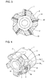
- FIGS 1 to 3 schematically show an entire indexable cutting tool according to an embodiment of the present invention.
- the indexable cutting tool includes a tool body 1, round inserts 10, and clamp screws 8.
- the round inserts 10 are mounted to the tool body 1.
- the clamp screws 8 secure the corresponding round inserts 10 to the tool body 1.
- Chip pockets 2 and support seats 3 facing the chip pockets 2 are provided at constant pitches in a peripheral direction along a periphery of an end of the tool body 1.
- Each support seat 3 has a seat bottom surface 3a (see Figs. 4 and 5 ) that supports a bottom surface 12 (see Figs. 8 and 9 ) of its corresponding round insert 10. Using the clamp screws 8, the round inserts 10 are mounted to the corresponding support seats 3.
- the clamp screws 8 are passed through mounting holes 15 (see Figs. 7 , 9 , 10 , and 12 ), which are provided in the centers of the corresponding round inserts 10, and are driven into threaded holes 4 (see Figs. 4 and 5 ), which are formed in the seat bottom surfaces 3a of the corresponding support seats 3.
- Each support seat 3, provided at the periphery of the end of the tool body 1, has, in addition to its corresponding seat bottom surface 3a, a first seat side surface 3b and a second seat side surface 3c shown in Figs. 4 to 6 .
- Each first seat side surface 3b and each second seat side surface 3c are surfaces that contact side surfaces 13 of its corresponding round insert 10 that are disposed 90 degrees apart from each other.
- Each first seat side surface 3b positions and supports its corresponding round insert 10 in an axial direction
- each second seat side surface 3c positions and supports the corresponding round insert 10 in a radial direction.
- a restraining section 5 including a vertically long restraining flute 5a and protrusions 5b between which the restraining flute is disposed is provided between each seat bottom surface 3a and its corresponding first seat side surface 3b.
- a first relief portion 6 and a second relief portion 7 that provide relief for a corner of the seat bottom surface 3a at the side of the first seat side surface 3b and a corner of the seat bottom surface 3a at the side of the second seat side surface 3c in a direction away from the round insert are provided at these corners of the corresponding seat bottom surface 3a.
- Each restraining flute 5a is a flute whose center is disposed on a line that is parallel to an axis of the tool passing through the center of its corresponding threaded hole 4.
- the protrusions 5b are disposed on the left and right of the corresponding restraining flute 5a.
- a restraining section 5 is not provided at the side of each second seat side surface 3c. This makes it possible to provide a wide region for setting each second relief portion 7.
- Each second relief portion 7 is formed in a range from the bottom surface 3a to the second seat side surface 3c of its corresponding support seat 3.
- Each second relief portion 7 is considerably larger than each first relief portion 6 that is formed in a range to the protrusions 5b from the bottom surface 3a of its corresponding support seat 3.
- each second relief portion 7 also depends upon the size of its corresponding round insert 10, it is possible to provide each second relief portion 7 in a region whose height is greater than or equal to 1/2 a height (thickness) H of the corresponding round insert 10. Its size is considerably larger than that in an existing cutting tool of the same type. Therefore, stress that is applied to the corner at the side of each support seat 3 where the second relief portion 7 is provided is reduced by being spread over a wide region. Consequently, fatigue and damage to the tool body caused by repeated application of the stress are effectively suppressed.
- Each first relief portion 6 is smaller than each second relief portion 7 since its setting is limited by the protrusions 5b.
- the rotating cutting tool such as a milling cutter
- a large stress which is applied to the corner at the side of the second seat side surface 3c of each support seat, is not applied to the corner at the side of the first seat side surface 3b of each support seat, problems resulting from the sizes of the first relief portions 6 being small do not particularly occur.
- Each round insert 10 is a positive insert in which each side surface 13 intersects its corresponding top surface 11 at an acute angle. Exemplary round inserts 10 are shown in Figs. 7 to 12 .
- An insert of a first form shown in Figs. 7 to 9 and an insert of a second form shown in Figs. 10 to 12 are both an indexable type in which a used cutting edge and an unused cutting edge are exchanged by rotation of the insert at a predetermined angle.
- the round insert 10 of the first form includes recessed portions 16a and ridges 16b, which are alternately provided at a pitch of 45 degrees in a peripheral direction.
- Each recessed portion 16a is a depression of a portion of a side surface 13 at a position towards a bottom surface 12 along a periphery.
- Each ridge 16b has a constant width.
- a cutting edge 14, formed at a ridge line at a portion where a top surface 11 and the side surface 13 intersect, can undergo rotation (undergo an exchange in position) by rotating the round insert 10 at an indexed angle of 45 degrees using a positioning section 16 including the recessed portions 16a and the ridges 16b.
- the round insert 10 of the second form is rotated by 90 degrees to cause a cutting edge 14 to undergo rotation, and includes recessed portions 16a and ridges 16b, which are alternately provided at a pitch of 90 degrees in a peripheral direction.
- Each recessed portion 16a is a depression of a portion of a side surface 13 at a position towards a bottom surface 12 along a periphery.
- Each ridge 16b has a constant width.
- one of the ridges 16b along the periphery of the bottom surface 12 side is inserted into and engaged with a restraining flute 5a formed in the tool body 1, and two protrusions 5b, formed on the tool body 1 so as to be disposed on both sides of the restraining flute 5a, are inserted into the recessed portions 16a on both sides of the ridge 16b inserted in the restraining flute 5a.
- each recessed portion 16a is a straight cylindrical surface that is concentric with an insert center.
- an end of each protrusion 5b, provided on the tool body 1 is tilted from the bottom surface of the corresponding recessed portion 16a in a substantially tangential direction when viewed from an insert end surface in Fig. 6 . Therefore, when engagement of the restraining flute 5a and the ridge 16b is no longer hindered, the round insert 10 is prevented from rotating by an engagement portion of the restraining flute 5a and the ridge 16b.
- a restraining flat surface Ff is provided at the bottom surface of each recessed portion 16a.
- the end of each protrusion 5b engageably faces its corresponding flat surface Ff.
- the round insert 10 is prevented from rotating even at the location where the ends of the protrusions 5b and the bottom surfaces of the recessed portions 16a engage with each other as well as at the location where the restraining flute 5a and the ridge 16b engage with each other. Therefore, the round insert 10 is more reliably prevented from rotating.
- the illustrated round insert 10 includes radially disposed flutes 17 in the top surface 11, serving as a rake face, it is not necessary to form the flutes 10.
- the bottom surface 12 is polygonal, it is not necessary for the bottom surface 12 to be polygonal.
Landscapes
- Engineering & Computer Science (AREA)
- Mechanical Engineering (AREA)
- Milling Processes (AREA)
- Cutting Tools, Boring Holders, And Turrets (AREA)
Abstract
Description
- The present invention relates to an indexable cutting tool including a circular cutting insert (what is called a "round insert") that is mounted to a support seat provided at a tool body.
- Regarding an indexable cutting tool in which a positive round insert and a tool body are combined, various structures for mounting the round insert to a support seat of the tool body are proposed.
- A method that is disclosed in, for example,
PTL 1 below is often used to mount a round insert to a tool body. In this method, the insert is positioned by contacting contact surfaces (restraining surfaces) with seat side surfaces provided in correspondence with a support seat of the tool body. The contact surfaces are formed at a constant pitch in a peripheral direction at a portion of the round insert towards a bottom surface at a periphery of the round insert by cutting portions of side surfaces of the round insert. Each contact surface is a flat surface having a tilt angle that is greater than that of the side surfaces. - In the cutting tool in
PTL 1, nicks are also provided, along with the contact surfaces, at the periphery of the insert, and protrusions formed on the tool body enter the nicks. This structure is for preventing erroneous mounting of the insert. The positioning of the insert is performed by simultaneously pushing, among the plurality of restraining surfaces, two surfaces that are set at an angle of 90 degrees from each other against two seat side surfaces of the support seat. - PTL 1: Japanese Patent No.
4857958 - In the above-described mounting structure in which the insert is restrained by contacting the flat contact surfaces, provided at the side surfaces of the insert, with the seat side surfaces of the support seat, it is difficult to increase positioning precision of the insert.
- Since the contact surfaces are formed at portions of the insert towards the bottom surface at the periphery of the insert, contact area of, in particular, a small insert with the seat side surfaces is small. In addition, since an unavoidable processing error occurs, it is very difficult to simultaneously closely contact two contact surfaces of the insert with two seat side surfaces of the tool body. Therefore, seating of the insert with respect to the support seat is poor, as a result of which precise positioning and stable securing of the insert cannot be expected.
- In the structure in which the bottom surface side at the periphery of the insert is restrained, thinned portions that are provided at corners (where the seat bottom surface and the seat side surfaces intersect each other) of the support seat cannot be made large because the area of the seat side surfaces of the support seat needs to be ensured. Therefore, stress that concentrates at the corners is not sufficiently reduced.
- In view of such a related art, it is an object of the present invention to make it possible to stably secure a round insert to a support seat with high precision and to reduce stress at corners of the support seat.
- To this end, the present invention provides an indexable cutting tool including a positive round insert that is mounted to a support seat provided at a periphery of an end of a tool body. The cutting tool has the following structure. A positioning section that positions a cutting edge, used in cutting, at an indexed point (position of use) is provided at a portion of the round insert towards a bottom surface at a periphery of the round insert. The support seat includes a first seat side surface, a second seat side surface, and a restraining section. The first seat side surface and the second seat side surface contact and support side surfaces of the round insert that are disposed 90 degrees apart from each other. The positioning section of the round insert is fitted to the restraining section (5) by bumpy portion fitting. Only one restraining section is provided between the seat bottom surface and the first seat side surface of the support seat. A first relief portion is provided at a corner at a side of the first seat side surface, and a second relief portion that is larger than the first relief portion is provided at a corner at a side of the second seat side surface.
- In such an indexable cutting tool, a specific example of the positioning section of the round insert may include recessed portions and ridges, which are alternately provided at a constant pitch in a peripheral direction at portions of the side surfaces towards the bottom surface of the round insert, each ridge having a constant width. In addition, the restraining section of the support seat may include a restraining flute and protrusions, the ridge engaging the restraining flute and the protrusions entering the recesses on two sides of the ridge.
- The second relief portion may be formed in a range from the seat bottom surface to the second seat side surface of the support seat.
- In comparison with a cutting tool of a type in which flat contact surfaces are provided at portions of a round insert towards the bottom surface at a periphery of the round insert and two contact surfaces are restrained by seat side surfaces, the cutting tool according to the present invention having the above-described structure can provide a wide contact area between the side surfaces of the round insert and the seat side surfaces of the support seat.
- The first seat side surface and the second seat side surface of the support seat are concentrically disposed. Therefore, it is possible to prevent the occurrence of unavoidable processing errors when the flat contact surfaces are provided 90 degrees apart from each other. This makes it possible to increase positioning precision and more stably secure the insert.
- The second relief portion can be made large by forming the second relief portion in a range extending from the seat bottom surface to the second seat side surface of the support seat. As a result, stress that is applied to the corner of the support seat at the side of the second seat side surface can be reduced by spreading the stress over a wide range. Although the size of the second relief portion depends upon the size of the round insert, the second relief portion is provided in a region whose size is greater than or equal to 1/3 times, desirably, 1/2 times the height (thickness between upper and lower surfaces) of the round insert.
- A round insert is ordinarily secured to a tool body by fastening the insert as a result of passing a clamp screw through a mounting hole in the center of the round insert and driving the clamp screw into a threaded hole formed in the seat bottom surface of the support seat. The cutting tool according to the present invention is also secured by this method.
- The positioning section (the recessed portion and ridge) that is provided at the round insert and the restraining section (the restraining flute and the protrusions) that is provided at the tool body are provided for the purpose of positioning the round insert at an indexed point. This purpose is also achieved by a structure in which the restraining section is provided between the seat bottom surface and the second seat side surface of the support seat. However, when the restraining section is provided between the seat bottom surface and the first seat side surface, the second relief portion is allowed to be formed at the side of the second seat side surface in a region extending from the seat bottom surface to the second seat side surface of the support seat.
- The end of each protrusion, provided at the tool body, may engageably face a bottom of the corresponding recessed portion, provided in the round insert, and the round insert may be positioned at an indexed point at a location where the restraining flute and the ridge engage with each other and at a location where the end of each protrusion and the bottom of the corresponding recessed portion engage with each other. This structure makes it possible to more reliably prevent rotation of the round insert.
- In the cutting tool according to the present invention, the support seat that is provided at the tool body includes a first seat side surface and a second seat side surface. In addition, the insert is positioned and supported by causing side surfaces at the upper side of the round insert that are disposed 90 degrees apart from each other to contact the first and second seat side surfaces. Therefore, it is possible to increase positioning precision and more stably secure the insert.
- In addition, since it is possible to increase the size of the second relief portion, it is possible to reduce stress that is applied to the corner of the support seat.
-
- [
Fig. 1] Figure 1 is a perspective view of an indexable cutting tool according to an embodiment of the present invention. - [
Fig. 2] Figure 2 is a side view of the cutting tool shown inFig. 1 . - [
Fig. 3] Figure 3 is a front view of the cutting tool shown inFig. 1 . - [
Fig. 4] Figure 4 is a perspective view of a tool body of the cutting tool shown inFig. 1 . - [
Fig. 5] Figure 5 is a perspective view of a support seat that is provided at the tool body shown inFig. 4 . - [
Fig. 6] Figure 6 illustrates the relationship between the position of the support seat of the tool body shown inFig. 4 and the position of a round insert mounted to the support seat. - [
Fig. 7] Figure 7 is a perspective view of the round insert that is used for the cutting tool shown inFig. 1 . - [
Fig. 8] Figure 8 is a side view of the round insert shown inFig. 7 . - [
Fig. 9] Figure 9 is a bottom view of the round insert shown inFig. 7 . - [
Fig. 10] Figure 10 is a perspective view of another round insert that is used for the cutting tool according to the present invention. - [
Fig. 11] Figure 11 is a side view of the round insert shown inFig. 10 . - [
Fig. 12] Figure 12 is a bottom view of the round insert shown inFig. 10 . - An embodiment of an indexable cutting tool according to the present invention is hereunder described with reference to
Figs. 1 to 12 of the attached drawings. -
Figures 1 to 3 schematically show an entire indexable cutting tool according to an embodiment of the present invention. The indexable cutting tool includes atool body 1, round inserts 10, and clamp screws 8. The round inserts 10 are mounted to thetool body 1. The clamp screws 8 secure the corresponding round inserts 10 to thetool body 1. - Chip pockets 2 and
support seats 3 facing the chip pockets 2 are provided at constant pitches in a peripheral direction along a periphery of an end of thetool body 1. Eachsupport seat 3 has a seatbottom surface 3a (seeFigs. 4 and5 ) that supports a bottom surface 12 (seeFigs. 8 and9 ) of its correspondinground insert 10. Using the clamp screws 8, the round inserts 10 are mounted to the corresponding support seats 3. - The clamp screws 8 are passed through mounting holes 15 (see
Figs. 7 ,9 ,10 , and12 ), which are provided in the centers of the corresponding round inserts 10, and are driven into threaded holes 4 (seeFigs. 4 and5 ), which are formed in the seat bottom surfaces 3a of the corresponding support seats 3. - Each
support seat 3, provided at the periphery of the end of thetool body 1, has, in addition to its corresponding seatbottom surface 3a, a firstseat side surface 3b and a secondseat side surface 3c shown inFigs. 4 to 6 . Each firstseat side surface 3b and each secondseat side surface 3c are surfaces that contact side surfaces 13 of its correspondinground insert 10 that are disposed 90 degrees apart from each other. Each firstseat side surface 3b positions and supports its correspondinground insert 10 in an axial direction, and each secondseat side surface 3c positions and supports the correspondinground insert 10 in a radial direction. - A restraining
section 5 including a vertically long restrainingflute 5a andprotrusions 5b between which the restraining flute is disposed is provided between eachseat bottom surface 3a and its corresponding firstseat side surface 3b. Afirst relief portion 6 and asecond relief portion 7 that provide relief for a corner of theseat bottom surface 3a at the side of the firstseat side surface 3b and a corner of theseat bottom surface 3a at the side of the secondseat side surface 3c in a direction away from the round insert are provided at these corners of the corresponding seatbottom surface 3a. - Each restraining
flute 5a is a flute whose center is disposed on a line that is parallel to an axis of the tool passing through the center of its corresponding threadedhole 4. Theprotrusions 5b are disposed on the left and right of the corresponding restrainingflute 5a. - A restraining
section 5 is not provided at the side of each secondseat side surface 3c. This makes it possible to provide a wide region for setting eachsecond relief portion 7. - Each
second relief portion 7 is formed in a range from thebottom surface 3a to the secondseat side surface 3c of itscorresponding support seat 3. Eachsecond relief portion 7 is considerably larger than eachfirst relief portion 6 that is formed in a range to theprotrusions 5b from thebottom surface 3a of itscorresponding support seat 3. - Although the size of each
second relief portion 7 also depends upon the size of its correspondinground insert 10, it is possible to provide eachsecond relief portion 7 in a region whose height is greater than or equal to 1/2 a height (thickness) H of the correspondinground insert 10. Its size is considerably larger than that in an existing cutting tool of the same type. Therefore, stress that is applied to the corner at the side of eachsupport seat 3 where thesecond relief portion 7 is provided is reduced by being spread over a wide region. Consequently, fatigue and damage to the tool body caused by repeated application of the stress are effectively suppressed. - Each
first relief portion 6 is smaller than eachsecond relief portion 7 since its setting is limited by theprotrusions 5b. However, in the rotating cutting tool, such as a milling cutter, since a large stress, which is applied to the corner at the side of the secondseat side surface 3c of each support seat, is not applied to the corner at the side of the firstseat side surface 3b of each support seat, problems resulting from the sizes of thefirst relief portions 6 being small do not particularly occur. - Each
round insert 10 is a positive insert in which eachside surface 13 intersects its correspondingtop surface 11 at an acute angle. Exemplary round inserts 10 are shown inFigs. 7 to 12 . - An insert of a first form shown in
Figs. 7 to 9 and an insert of a second form shown inFigs. 10 to 12 are both an indexable type in which a used cutting edge and an unused cutting edge are exchanged by rotation of the insert at a predetermined angle. - The
round insert 10 of the first form includes recessedportions 16a andridges 16b, which are alternately provided at a pitch of 45 degrees in a peripheral direction. Each recessedportion 16a is a depression of a portion of aside surface 13 at a position towards abottom surface 12 along a periphery. Eachridge 16b has a constant width. Acutting edge 14, formed at a ridge line at a portion where atop surface 11 and theside surface 13 intersect, can undergo rotation (undergo an exchange in position) by rotating theround insert 10 at an indexed angle of 45 degrees using apositioning section 16 including the recessedportions 16a and theridges 16b. - The
round insert 10 of the second form is rotated by 90 degrees to cause acutting edge 14 to undergo rotation, and includes recessedportions 16a andridges 16b, which are alternately provided at a pitch of 90 degrees in a peripheral direction. Each recessedportion 16a is a depression of a portion of aside surface 13 at a position towards abottom surface 12 along a periphery. Eachridge 16b has a constant width. - Side surfaces 13 at the upper side of the
round insert 10 that are disposed 90 degrees apart from each other are contacted with a firstseat side surface 3b and a secondseat side surface 3c, respectively, and positioning in an axial direction is performed by the firstseat side surface 3b, and positioning in a radial direction is performed by the secondseat side surface 3c, so that theround insert 10 is placed on asupport seat 3. At this time, one of theridges 16b along the periphery of thebottom surface 12 side is inserted into and engaged with a restrainingflute 5a formed in thetool body 1, and twoprotrusions 5b, formed on thetool body 1 so as to be disposed on both sides of the restrainingflute 5a, are inserted into the recessedportions 16a on both sides of theridge 16b inserted in the restrainingflute 5a. - In the
round insert 10 of the first form, the bottom surface of each recessedportion 16a is a straight cylindrical surface that is concentric with an insert center. In addition, an end of eachprotrusion 5b, provided on thetool body 1, is tilted from the bottom surface of the corresponding recessedportion 16a in a substantially tangential direction when viewed from an insert end surface inFig. 6 . Therefore, when engagement of the restrainingflute 5a and theridge 16b is no longer hindered, theround insert 10 is prevented from rotating by an engagement portion of the restrainingflute 5a and theridge 16b. - In contrast, in the
round insert 10 of the second form, a restraining flat surface Ff is provided at the bottom surface of each recessedportion 16a. In addition, with an end of eachprotrusion 5b, provided on thetool body 1, having a flat surface that is perpendicular to an axis of the tool, the end of eachprotrusion 5b engageably faces its corresponding flat surface Ff. Theround insert 10 is prevented from rotating even at the location where the ends of theprotrusions 5b and the bottom surfaces of the recessedportions 16a engage with each other as well as at the location where the restrainingflute 5a and theridge 16b engage with each other. Therefore, theround insert 10 is more reliably prevented from rotating. - Although the illustrated
round insert 10 includes radially disposedflutes 17 in thetop surface 11, serving as a rake face, it is not necessary to form theflutes 10. In addition, although thebottom surface 12 is polygonal, it is not necessary for thebottom surface 12 to be polygonal. -
- 1
- tool body
- 2
- chip pocket
- 3
- support seat
- 3a
- bottom surface
- 3b
- first seat side surface
- 3c
- second seat side surface
- 4
- threaded hole
- 5
- restraining section
- 5a
- restraining flute
- 5b
- protrusion
- 6
- first relief portion
- 7
- second relief portion
- 8
- clamp screw
- 10
- round insert
- 11
- top surface
- 12
- bottom surface
- 13
- side surface
- 14
- cutting edge
- 15
- mounting hole
- 16
- positioning section
- 16a
- recessed portion
- 16b
- ridge
- Ff
- flat surface included at bottom surface of recessed portion
- 17
- flute
Claims (4)
- An indexable cutting tool comprising a positive round insert (10) that is mounted to a support seat (3) provided at a periphery of an end of a tool body (1),
wherein a positioning section (16) that positions a cutting edge, used in cutting, at an indexed point is provided at a portion of the round insert (10) towards a bottom surface (12) at a periphery of the round insert (10),
wherein the support seat (3) includes a first seat side surface (3b), a second seat side surface (3c), and a restraining section (5), the first seat side surface (3b) and the second seat side surface (3c) contacting and supporting side surfaces (13) of the round insert (10) that are disposed 90 degrees apart from each other, the positioning section (16) of the round insert (10) being fitted to the restraining section (5) by bumpy portion fitting,
wherein only one restraining section (5) is provided between the seat bottom surface (3a) and the first seat side surface (3b) of the support seat, and
wherein a first relief portion (6) is provided at a corner at a side of the first seat side surface (3b), and a second relief portion (7) that is larger than the first relief portion is provided at a corner at a side of the second seat side surface (3c). - The indexable cutting tool according to Claim 1, wherein the positioning section (16) of the round insert includes recessed portions (16a) and ridges (16b), which are alternately provided at a constant pitch in a peripheral direction at portions of the side surfaces (13) towards the bottom surface (12) of the round insert (10), each ridge (16b) having a constant width, and
wherein the restraining section (5) of the support seat include a restraining flute (5a) and protrusions (5b), the ridge (16b) engaging the restraining flute (5a), the protrusions (5b) entering the recesses (16a, 16a) on two sides of the ridge (16b). - The indexable cutting tool according to Claim 1 or Claim 2, wherein the second relief portion (7) is formed in a range from the seat bottom surface (3a) to the second seat side surface (3c) of the support seat.
- The indexable cutting tool according to Claim 2 or Claim 3, wherein the end of each protrusion (5b), provided at the tool body (1), engageably faces a bottom of the corresponding recessed portion (16a), provided in the round insert (10), and
wherein the round insert (10) is prevented from rotating at a location where the restraining flute (5a) and the ridge (16b) engage with each other and at a location where the end of each protrusion (5b) and the bottom of the corresponding recessed portion (16a) engage with each other.
Applications Claiming Priority (2)
| Application Number | Priority Date | Filing Date | Title |
|---|---|---|---|
| JP2012163673A JP5853297B2 (en) | 2012-07-24 | 2012-07-24 | Replaceable cutting tool |
| PCT/JP2013/061451 WO2014017133A1 (en) | 2012-07-24 | 2013-04-18 | Indexable cutting tool |
Publications (3)
| Publication Number | Publication Date |
|---|---|
| EP2878405A1 true EP2878405A1 (en) | 2015-06-03 |
| EP2878405A4 EP2878405A4 (en) | 2016-05-18 |
| EP2878405B1 EP2878405B1 (en) | 2017-05-17 |
Family
ID=49996952
Family Applications (1)
| Application Number | Title | Priority Date | Filing Date |
|---|---|---|---|
| EP13822271.6A Active EP2878405B1 (en) | 2012-07-24 | 2013-04-18 | Indexable cutting tool |
Country Status (5)
| Country | Link |
|---|---|
| US (1) | US9409240B2 (en) |
| EP (1) | EP2878405B1 (en) |
| JP (1) | JP5853297B2 (en) |
| CN (1) | CN104093514B (en) |
| WO (1) | WO2014017133A1 (en) |
Cited By (1)
| Publication number | Priority date | Publication date | Assignee | Title |
|---|---|---|---|---|
| EP3643439A1 (en) * | 2018-10-26 | 2020-04-29 | Seco Tools Ab | A cutting tool |
Families Citing this family (19)
| Publication number | Priority date | Publication date | Assignee | Title |
|---|---|---|---|---|
| WO2013051703A1 (en) * | 2011-10-07 | 2013-04-11 | 株式会社タンガロイ | Cutting tool with replaceable blade edge |
| JP1522102S (en) * | 2014-05-12 | 2015-04-20 | ||
| CN106457423B (en) * | 2014-06-24 | 2018-09-07 | 住友电工硬质合金株式会社 | Cutting tool and cutter body |
| KR101529524B1 (en) * | 2014-08-18 | 2015-06-17 | 한국야금 주식회사 | Cutting insert and tool holder for mounting the same |
| US9862039B2 (en) * | 2014-08-28 | 2018-01-09 | Richard Theriault | Milling tool with rotatable cutting disks |
| US10406608B2 (en) * | 2015-01-19 | 2019-09-10 | Kennametal Inc. | Cutting insert and pocket with uninterrupted and continuous seating surface perimeter |
| CN107000082B (en) | 2015-03-05 | 2020-03-13 | 株式会社泰珂洛 | Cutting insert and cutting edge replaceable rotary cutting tool |
| CN107405702B (en) * | 2015-05-19 | 2019-09-27 | 株式会社泰珂洛 | Tool bodies and cutting tools |
| CN107570735B (en) * | 2017-09-30 | 2020-04-10 | 株洲钻石切削刀具股份有限公司 | Polygonal cutting blade with arc-shaped groove in hole and cutting tool |
| CN107775019B (en) * | 2017-09-30 | 2020-04-28 | 株洲钻石切削刀具股份有限公司 | Polygonal cutting blade with boss in hole and cutting tool |
| US10646927B2 (en) * | 2018-02-19 | 2020-05-12 | Iscar, Ltd. | Round double-sided cutting insert having a peripheral surface provided with protruding indexing latches, insert holder therefor and cutting tool |
| CN109822141A (en) * | 2019-03-26 | 2019-05-31 | 哈尔滨汽轮机厂有限责任公司 | Finishing and roughing inserts for machining superalloy blades of steam turbines |
| CN112108697B (en) * | 2019-06-20 | 2024-08-06 | 肯纳金属印度有限公司 | Tool holder with pockets for receiving cutting inserts having different clearance angles |
| KR102253026B1 (en) * | 2019-10-28 | 2021-05-17 | 한국야금 주식회사 | Cutting insert and Tool mounted withthere |
| USD1040196S1 (en) * | 2020-12-18 | 2024-08-27 | Sumitomo Electric Hardmetal Corp. | Cutting tool |
| JP7012948B1 (en) * | 2021-03-10 | 2022-01-31 | 株式会社タンガロイ | Tool body of replaceable cutting tool |
| USD1037327S1 (en) * | 2021-08-26 | 2024-07-30 | Sumitomo Electric Hardmetal Corp. | Cutting tool |
| USD1037326S1 (en) * | 2021-08-26 | 2024-07-30 | Sumitomo Electric Hardmetal Corp. | Cutting tool insert |
| JP1714663S (en) * | 2021-08-26 | 2022-05-12 | Main body for cutting tools |
Family Cites Families (10)
| Publication number | Priority date | Publication date | Assignee | Title |
|---|---|---|---|---|
| KR100430348B1 (en) | 1995-07-18 | 2004-06-16 | 산드빅 악티에볼라그 | Tool for metal cutting |
| IL119841A (en) * | 1996-12-16 | 2000-02-29 | Iscar Ltd | Cutting inserts |
| US6238133B1 (en) | 1998-10-20 | 2001-05-29 | Kennametal Pc Inc. | Anti-rotation mounting mechanism for round cutting insert |
| IL150783A0 (en) | 2001-10-16 | 2003-02-12 | Iscar Ltd | Cutting tool and cutting insert therefor |
| US7722297B2 (en) | 2003-04-15 | 2010-05-25 | Tdy Industries, Inc. | Antirotation tool holder and cutting insert |
| JP4857958B2 (en) * | 2006-01-11 | 2012-01-18 | 三菱マテリアル株式会社 | Round piece insert removable cutting tool and round piece insert |
| SE530701C2 (en) | 2006-12-21 | 2008-08-19 | Sandvik Intellectual Property | Turning tools and lathe inserts where the engaging means of the insert are located in the triangle |
| JP5185322B2 (en) * | 2010-05-26 | 2013-04-17 | 住友電工ハードメタル株式会社 | Cutting tools |
| SE536344C2 (en) * | 2012-01-30 | 2013-09-03 | Sandvik Intellectual Property | Milling tools and milling cutters where the cutting edge has an acute pitch |
| US9011049B2 (en) * | 2012-09-25 | 2015-04-21 | Kennametal Inc. | Double-sided cutting inserts with anti-rotation features |
-
2012
- 2012-07-24 JP JP2012163673A patent/JP5853297B2/en active Active
-
2013
- 2013-04-18 US US14/370,119 patent/US9409240B2/en active Active
- 2013-04-18 EP EP13822271.6A patent/EP2878405B1/en active Active
- 2013-04-18 WO PCT/JP2013/061451 patent/WO2014017133A1/en not_active Ceased
- 2013-04-18 CN CN201380006550.8A patent/CN104093514B/en active Active
Cited By (3)
| Publication number | Priority date | Publication date | Assignee | Title |
|---|---|---|---|---|
| EP3643439A1 (en) * | 2018-10-26 | 2020-04-29 | Seco Tools Ab | A cutting tool |
| WO2020083896A1 (en) * | 2018-10-26 | 2020-04-30 | Seco Tools Ab | A cutting tool |
| US12064822B2 (en) | 2018-10-26 | 2024-08-20 | Seco Tools Ab | Cutting tool |
Also Published As
| Publication number | Publication date |
|---|---|
| EP2878405A4 (en) | 2016-05-18 |
| US20140348600A1 (en) | 2014-11-27 |
| JP5853297B2 (en) | 2016-02-09 |
| US9409240B2 (en) | 2016-08-09 |
| WO2014017133A1 (en) | 2014-01-30 |
| CN104093514B (en) | 2016-05-25 |
| CN104093514A (en) | 2014-10-08 |
| JP2014024124A (en) | 2014-02-06 |
| EP2878405B1 (en) | 2017-05-17 |
Similar Documents
| Publication | Publication Date | Title |
|---|---|---|
| EP2878405B1 (en) | Indexable cutting tool | |
| EP2764939B1 (en) | Cutting tool with replaceable blade edge | |
| EP2623240B1 (en) | Blade edge exchangeable cutting tool | |
| EP2934803B1 (en) | Milling cutter including a cutting insert | |
| KR101237168B1 (en) | Cutting insert, cartiridge for cutting tool, and cutting tool | |
| EP2664399B1 (en) | Cutting tool | |
| EP2981386B1 (en) | Indexable double-sided milling cutting insert | |
| EP2616201B1 (en) | Pin miller inserts and a cutter using the same | |
| KR20100124637A (en) | Double-sided cutting insert having a circular shape and cutting tool using the same | |
| JP2016539010A (en) | Positionable milling insert with side support indentation and milling tool | |
| US20130129434A1 (en) | Cutting Insert and Indexable Rotary Cutting Tool | |
| JP5185322B2 (en) | Cutting tools | |
| KR101238850B1 (en) | Insert and side cutter | |
| US9227246B2 (en) | Cutting tool for grooving and parting operations | |
| CN106660148A (en) | Cutting tools and cutting inserts for chip removal tools | |
| EP2865473B1 (en) | Cutting insert, tool body on which said cutting insert may be mounted, and replaceable-blade-type ball-end mill provided therewith | |
| JP2014200878A (en) | Cutting insert and tip replaceable cutting tool | |
| CN109414768B (en) | Cutting inserts and milling tools for milling tools | |
| CN118305343B (en) | Indexable cutting tool | |
| JP6253093B2 (en) | Cutting insert and cutting edge exchangeable cutting tool | |
| RU2466831C2 (en) | Cutting plate | |
| US20190151963A1 (en) | Rotary cutting tool having disk-shaped cutting body and indexable cutting insert therefor |
Legal Events
| Date | Code | Title | Description |
|---|---|---|---|
| PUAI | Public reference made under article 153(3) epc to a published international application that has entered the european phase |
Free format text: ORIGINAL CODE: 0009012 |
|
| 17P | Request for examination filed |
Effective date: 20140722 |
|
| AK | Designated contracting states |
Kind code of ref document: A1 Designated state(s): AL AT BE BG CH CY CZ DE DK EE ES FI FR GB GR HR HU IE IS IT LI LT LU LV MC MK MT NL NO PL PT RO RS SE SI SK SM TR |
|
| AX | Request for extension of the european patent |
Extension state: BA ME |
|
| DAX | Request for extension of the european patent (deleted) | ||
| RA4 | Supplementary search report drawn up and despatched (corrected) |
Effective date: 20160418 |
|
| RIC1 | Information provided on ipc code assigned before grant |
Ipc: B23C 5/06 20060101ALI20160412BHEP Ipc: B23C 5/22 20060101AFI20160412BHEP |
|
| GRAP | Despatch of communication of intention to grant a patent |
Free format text: ORIGINAL CODE: EPIDOSNIGR1 |
|
| INTG | Intention to grant announced |
Effective date: 20161124 |
|
| GRAS | Grant fee paid |
Free format text: ORIGINAL CODE: EPIDOSNIGR3 |
|
| GRAA | (expected) grant |
Free format text: ORIGINAL CODE: 0009210 |
|
| AK | Designated contracting states |
Kind code of ref document: B1 Designated state(s): AL AT BE BG CH CY CZ DE DK EE ES FI FR GB GR HR HU IE IS IT LI LT LU LV MC MK MT NL NO PL PT RO RS SE SI SK SM TR |
|
| REG | Reference to a national code |
Ref country code: GB Ref legal event code: FG4D |
|
| REG | Reference to a national code |
Ref country code: CH Ref legal event code: EP |
|
| REG | Reference to a national code |
Ref country code: IE Ref legal event code: FG4D |
|
| REG | Reference to a national code |
Ref country code: AT Ref legal event code: REF Ref document number: 894016 Country of ref document: AT Kind code of ref document: T Effective date: 20170615 |
|
| REG | Reference to a national code |
Ref country code: DE Ref legal event code: R096 Ref document number: 602013021396 Country of ref document: DE |
|
| REG | Reference to a national code |
Ref country code: NL Ref legal event code: MP Effective date: 20170517 |
|
| REG | Reference to a national code |
Ref country code: LT Ref legal event code: MG4D |
|
| REG | Reference to a national code |
Ref country code: AT Ref legal event code: MK05 Ref document number: 894016 Country of ref document: AT Kind code of ref document: T Effective date: 20170517 |
|
| PG25 | Lapsed in a contracting state [announced via postgrant information from national office to epo] |
Ref country code: AT Free format text: LAPSE BECAUSE OF FAILURE TO SUBMIT A TRANSLATION OF THE DESCRIPTION OR TO PAY THE FEE WITHIN THE PRESCRIBED TIME-LIMIT Effective date: 20170517 Ref country code: ES Free format text: LAPSE BECAUSE OF FAILURE TO SUBMIT A TRANSLATION OF THE DESCRIPTION OR TO PAY THE FEE WITHIN THE PRESCRIBED TIME-LIMIT Effective date: 20170517 Ref country code: GR Free format text: LAPSE BECAUSE OF FAILURE TO SUBMIT A TRANSLATION OF THE DESCRIPTION OR TO PAY THE FEE WITHIN THE PRESCRIBED TIME-LIMIT Effective date: 20170818 Ref country code: FI Free format text: LAPSE BECAUSE OF FAILURE TO SUBMIT A TRANSLATION OF THE DESCRIPTION OR TO PAY THE FEE WITHIN THE PRESCRIBED TIME-LIMIT Effective date: 20170517 Ref country code: HR Free format text: LAPSE BECAUSE OF FAILURE TO SUBMIT A TRANSLATION OF THE DESCRIPTION OR TO PAY THE FEE WITHIN THE PRESCRIBED TIME-LIMIT Effective date: 20170517 Ref country code: LT Free format text: LAPSE BECAUSE OF FAILURE TO SUBMIT A TRANSLATION OF THE DESCRIPTION OR TO PAY THE FEE WITHIN THE PRESCRIBED TIME-LIMIT Effective date: 20170517 Ref country code: NO Free format text: LAPSE BECAUSE OF FAILURE TO SUBMIT A TRANSLATION OF THE DESCRIPTION OR TO PAY THE FEE WITHIN THE PRESCRIBED TIME-LIMIT Effective date: 20170817 |
|
| PG25 | Lapsed in a contracting state [announced via postgrant information from national office to epo] |
Ref country code: PL Free format text: LAPSE BECAUSE OF FAILURE TO SUBMIT A TRANSLATION OF THE DESCRIPTION OR TO PAY THE FEE WITHIN THE PRESCRIBED TIME-LIMIT Effective date: 20170517 Ref country code: NL Free format text: LAPSE BECAUSE OF FAILURE TO SUBMIT A TRANSLATION OF THE DESCRIPTION OR TO PAY THE FEE WITHIN THE PRESCRIBED TIME-LIMIT Effective date: 20170517 Ref country code: LV Free format text: LAPSE BECAUSE OF FAILURE TO SUBMIT A TRANSLATION OF THE DESCRIPTION OR TO PAY THE FEE WITHIN THE PRESCRIBED TIME-LIMIT Effective date: 20170517 Ref country code: BG Free format text: LAPSE BECAUSE OF FAILURE TO SUBMIT A TRANSLATION OF THE DESCRIPTION OR TO PAY THE FEE WITHIN THE PRESCRIBED TIME-LIMIT Effective date: 20170817 Ref country code: IS Free format text: LAPSE BECAUSE OF FAILURE TO SUBMIT A TRANSLATION OF THE DESCRIPTION OR TO PAY THE FEE WITHIN THE PRESCRIBED TIME-LIMIT Effective date: 20170917 Ref country code: RS Free format text: LAPSE BECAUSE OF FAILURE TO SUBMIT A TRANSLATION OF THE DESCRIPTION OR TO PAY THE FEE WITHIN THE PRESCRIBED TIME-LIMIT Effective date: 20170517 Ref country code: SE Free format text: LAPSE BECAUSE OF FAILURE TO SUBMIT A TRANSLATION OF THE DESCRIPTION OR TO PAY THE FEE WITHIN THE PRESCRIBED TIME-LIMIT Effective date: 20170517 |
|
| PG25 | Lapsed in a contracting state [announced via postgrant information from national office to epo] |
Ref country code: DK Free format text: LAPSE BECAUSE OF FAILURE TO SUBMIT A TRANSLATION OF THE DESCRIPTION OR TO PAY THE FEE WITHIN THE PRESCRIBED TIME-LIMIT Effective date: 20170517 Ref country code: RO Free format text: LAPSE BECAUSE OF FAILURE TO SUBMIT A TRANSLATION OF THE DESCRIPTION OR TO PAY THE FEE WITHIN THE PRESCRIBED TIME-LIMIT Effective date: 20170517 Ref country code: EE Free format text: LAPSE BECAUSE OF FAILURE TO SUBMIT A TRANSLATION OF THE DESCRIPTION OR TO PAY THE FEE WITHIN THE PRESCRIBED TIME-LIMIT Effective date: 20170517 Ref country code: SK Free format text: LAPSE BECAUSE OF FAILURE TO SUBMIT A TRANSLATION OF THE DESCRIPTION OR TO PAY THE FEE WITHIN THE PRESCRIBED TIME-LIMIT Effective date: 20170517 Ref country code: CZ Free format text: LAPSE BECAUSE OF FAILURE TO SUBMIT A TRANSLATION OF THE DESCRIPTION OR TO PAY THE FEE WITHIN THE PRESCRIBED TIME-LIMIT Effective date: 20170517 |
|
| REG | Reference to a national code |
Ref country code: DE Ref legal event code: R097 Ref document number: 602013021396 Country of ref document: DE |
|
| PG25 | Lapsed in a contracting state [announced via postgrant information from national office to epo] |
Ref country code: SM Free format text: LAPSE BECAUSE OF FAILURE TO SUBMIT A TRANSLATION OF THE DESCRIPTION OR TO PAY THE FEE WITHIN THE PRESCRIBED TIME-LIMIT Effective date: 20170517 |
|
| REG | Reference to a national code |
Ref country code: FR Ref legal event code: PLFP Year of fee payment: 6 |
|
| PLBE | No opposition filed within time limit |
Free format text: ORIGINAL CODE: 0009261 |
|
| STAA | Information on the status of an ep patent application or granted ep patent |
Free format text: STATUS: NO OPPOSITION FILED WITHIN TIME LIMIT |
|
| 26N | No opposition filed |
Effective date: 20180220 |
|
| PG25 | Lapsed in a contracting state [announced via postgrant information from national office to epo] |
Ref country code: SI Free format text: LAPSE BECAUSE OF FAILURE TO SUBMIT A TRANSLATION OF THE DESCRIPTION OR TO PAY THE FEE WITHIN THE PRESCRIBED TIME-LIMIT Effective date: 20170517 |
|
| PG25 | Lapsed in a contracting state [announced via postgrant information from national office to epo] |
Ref country code: MC Free format text: LAPSE BECAUSE OF FAILURE TO SUBMIT A TRANSLATION OF THE DESCRIPTION OR TO PAY THE FEE WITHIN THE PRESCRIBED TIME-LIMIT Effective date: 20170517 |
|
| REG | Reference to a national code |
Ref country code: CH Ref legal event code: PL |
|
| REG | Reference to a national code |
Ref country code: BE Ref legal event code: MM Effective date: 20180430 |
|
| GBPC | Gb: european patent ceased through non-payment of renewal fee |
Effective date: 20180418 |
|
| REG | Reference to a national code |
Ref country code: IE Ref legal event code: MM4A |
|
| PG25 | Lapsed in a contracting state [announced via postgrant information from national office to epo] |
Ref country code: LU Free format text: LAPSE BECAUSE OF NON-PAYMENT OF DUE FEES Effective date: 20180418 |
|
| PG25 | Lapsed in a contracting state [announced via postgrant information from national office to epo] |
Ref country code: LI Free format text: LAPSE BECAUSE OF NON-PAYMENT OF DUE FEES Effective date: 20180430 Ref country code: CH Free format text: LAPSE BECAUSE OF NON-PAYMENT OF DUE FEES Effective date: 20180430 Ref country code: BE Free format text: LAPSE BECAUSE OF NON-PAYMENT OF DUE FEES Effective date: 20180430 Ref country code: GB Free format text: LAPSE BECAUSE OF NON-PAYMENT OF DUE FEES Effective date: 20180418 |
|
| PG25 | Lapsed in a contracting state [announced via postgrant information from national office to epo] |
Ref country code: IE Free format text: LAPSE BECAUSE OF NON-PAYMENT OF DUE FEES Effective date: 20180418 |
|
| PGFP | Annual fee paid to national office [announced via postgrant information from national office to epo] |
Ref country code: FR Payment date: 20190313 Year of fee payment: 7 |
|
| PGFP | Annual fee paid to national office [announced via postgrant information from national office to epo] |
Ref country code: IT Payment date: 20190419 Year of fee payment: 7 |
|
| PG25 | Lapsed in a contracting state [announced via postgrant information from national office to epo] |
Ref country code: MT Free format text: LAPSE BECAUSE OF NON-PAYMENT OF DUE FEES Effective date: 20180418 |
|
| PG25 | Lapsed in a contracting state [announced via postgrant information from national office to epo] |
Ref country code: TR Free format text: LAPSE BECAUSE OF FAILURE TO SUBMIT A TRANSLATION OF THE DESCRIPTION OR TO PAY THE FEE WITHIN THE PRESCRIBED TIME-LIMIT Effective date: 20170517 |
|
| PG25 | Lapsed in a contracting state [announced via postgrant information from national office to epo] |
Ref country code: PT Free format text: LAPSE BECAUSE OF FAILURE TO SUBMIT A TRANSLATION OF THE DESCRIPTION OR TO PAY THE FEE WITHIN THE PRESCRIBED TIME-LIMIT Effective date: 20170517 |
|
| PG25 | Lapsed in a contracting state [announced via postgrant information from national office to epo] |
Ref country code: CY Free format text: LAPSE BECAUSE OF FAILURE TO SUBMIT A TRANSLATION OF THE DESCRIPTION OR TO PAY THE FEE WITHIN THE PRESCRIBED TIME-LIMIT Effective date: 20170517 Ref country code: MK Free format text: LAPSE BECAUSE OF NON-PAYMENT OF DUE FEES Effective date: 20170517 Ref country code: HU Free format text: LAPSE BECAUSE OF FAILURE TO SUBMIT A TRANSLATION OF THE DESCRIPTION OR TO PAY THE FEE WITHIN THE PRESCRIBED TIME-LIMIT; INVALID AB INITIO Effective date: 20130418 |
|
| PG25 | Lapsed in a contracting state [announced via postgrant information from national office to epo] |
Ref country code: AL Free format text: LAPSE BECAUSE OF FAILURE TO SUBMIT A TRANSLATION OF THE DESCRIPTION OR TO PAY THE FEE WITHIN THE PRESCRIBED TIME-LIMIT Effective date: 20170517 |
|
| PG25 | Lapsed in a contracting state [announced via postgrant information from national office to epo] |
Ref country code: FR Free format text: LAPSE BECAUSE OF NON-PAYMENT OF DUE FEES Effective date: 20200430 |
|
| PG25 | Lapsed in a contracting state [announced via postgrant information from national office to epo] |
Ref country code: IT Free format text: LAPSE BECAUSE OF NON-PAYMENT OF DUE FEES Effective date: 20200418 |
|
| P01 | Opt-out of the competence of the unified patent court (upc) registered |
Effective date: 20230515 |
|
| PGFP | Annual fee paid to national office [announced via postgrant information from national office to epo] |
Ref country code: DE Payment date: 20250305 Year of fee payment: 13 |