EP2878392A1 - Press-forming mold and method for manufacturing press-formed product - Google Patents
Press-forming mold and method for manufacturing press-formed product Download PDFInfo
- Publication number
- EP2878392A1 EP2878392A1 EP12890327.5A EP12890327A EP2878392A1 EP 2878392 A1 EP2878392 A1 EP 2878392A1 EP 12890327 A EP12890327 A EP 12890327A EP 2878392 A1 EP2878392 A1 EP 2878392A1
- Authority
- EP
- European Patent Office
- Prior art keywords
- press
- wrinkle suppression
- forming
- pressure receiving
- formed product
- Prior art date
- Legal status (The legal status is an assumption and is not a legal conclusion. Google has not performed a legal analysis and makes no representation as to the accuracy of the status listed.)
- Granted
Links
Images





Classifications
-
- B—PERFORMING OPERATIONS; TRANSPORTING
- B21—MECHANICAL METAL-WORKING WITHOUT ESSENTIALLY REMOVING MATERIAL; PUNCHING METAL
- B21D—WORKING OR PROCESSING OF SHEET METAL OR METAL TUBES, RODS OR PROFILES WITHOUT ESSENTIALLY REMOVING MATERIAL; PUNCHING METAL
- B21D24/00—Special deep-drawing arrangements in, or in connection with, presses
- B21D24/10—Devices controlling or operating blank holders independently, or in conjunction with dies
- B21D24/12—Devices controlling or operating blank holders independently, or in conjunction with dies mechanically
-
- B—PERFORMING OPERATIONS; TRANSPORTING
- B21—MECHANICAL METAL-WORKING WITHOUT ESSENTIALLY REMOVING MATERIAL; PUNCHING METAL
- B21D—WORKING OR PROCESSING OF SHEET METAL OR METAL TUBES, RODS OR PROFILES WITHOUT ESSENTIALLY REMOVING MATERIAL; PUNCHING METAL
- B21D22/00—Shaping without cutting, by stamping, spinning, or deep-drawing
- B21D22/20—Deep-drawing
- B21D22/22—Deep-drawing with devices for holding the edge of the blanks
-
- B—PERFORMING OPERATIONS; TRANSPORTING
- B21—MECHANICAL METAL-WORKING WITHOUT ESSENTIALLY REMOVING MATERIAL; PUNCHING METAL
- B21D—WORKING OR PROCESSING OF SHEET METAL OR METAL TUBES, RODS OR PROFILES WITHOUT ESSENTIALLY REMOVING MATERIAL; PUNCHING METAL
- B21D22/00—Shaping without cutting, by stamping, spinning, or deep-drawing
- B21D22/20—Deep-drawing
- B21D22/26—Deep-drawing for making peculiarly, e.g. irregularly, shaped articles
-
- B—PERFORMING OPERATIONS; TRANSPORTING
- B21—MECHANICAL METAL-WORKING WITHOUT ESSENTIALLY REMOVING MATERIAL; PUNCHING METAL
- B21D—WORKING OR PROCESSING OF SHEET METAL OR METAL TUBES, RODS OR PROFILES WITHOUT ESSENTIALLY REMOVING MATERIAL; PUNCHING METAL
- B21D5/00—Bending sheet metal along straight lines, e.g. to form simple curves
- B21D5/01—Bending sheet metal along straight lines, e.g. to form simple curves between rams and anvils or abutments
-
- B—PERFORMING OPERATIONS; TRANSPORTING
- B21—MECHANICAL METAL-WORKING WITHOUT ESSENTIALLY REMOVING MATERIAL; PUNCHING METAL
- B21J—FORGING; HAMMERING; PRESSING METAL; RIVETING; FORGE FURNACES
- B21J13/00—Details of machines for forging, pressing, or hammering
- B21J13/02—Dies or mountings therefor
-
- B—PERFORMING OPERATIONS; TRANSPORTING
- B21—MECHANICAL METAL-WORKING WITHOUT ESSENTIALLY REMOVING MATERIAL; PUNCHING METAL
- B21J—FORGING; HAMMERING; PRESSING METAL; RIVETING; FORGE FURNACES
- B21J5/00—Methods for forging, hammering, or pressing; Special equipment or accessories therefor
-
- B—PERFORMING OPERATIONS; TRANSPORTING
- B21—MECHANICAL METAL-WORKING WITHOUT ESSENTIALLY REMOVING MATERIAL; PUNCHING METAL
- B21D—WORKING OR PROCESSING OF SHEET METAL OR METAL TUBES, RODS OR PROFILES WITHOUT ESSENTIALLY REMOVING MATERIAL; PUNCHING METAL
- B21D24/00—Special deep-drawing arrangements in, or in connection with, presses
- B21D24/04—Blank holders; Mounting means therefor
-
- B—PERFORMING OPERATIONS; TRANSPORTING
- B21—MECHANICAL METAL-WORKING WITHOUT ESSENTIALLY REMOVING MATERIAL; PUNCHING METAL
- B21D—WORKING OR PROCESSING OF SHEET METAL OR METAL TUBES, RODS OR PROFILES WITHOUT ESSENTIALLY REMOVING MATERIAL; PUNCHING METAL
- B21D53/00—Making other particular articles
- B21D53/88—Making other particular articles other parts for vehicles, e.g. cowlings, mudguards
Definitions
- the present invention relates to a press-forming tool for a metal plate, and a method for manufacturing a press-formed product which is press-formed using the press-forming tool.
- the present invention relates to a press-forming tool and a method for manufacturing a press-formed product for securing improved shape freezing properties by decreasing springback which is generated after the press forming is performed.
- the springback is generated since the press-formed product is deformed by elastic recovery after the press forming due to residual stress introduced into the metal plate during the press forming.
- the residual stress introduced into the metal plate is non-uniformly distributed in a plate thickness direction or an in-plane direction of the metal plate, the springback is easily generated.
- a press forming apparatus which includes a variable die cushion device using a servo valve or the like, is generally required.
- Patent Document 1 discloses a press-forming tool in which an elastic body such as a spring is disposed in the press-forming tool. In this press-forming tool, it is possible to increase the wrinkle suppression force in the end phase of the press forming without the variable die cushion device.
- Patent Document 2 discloses a press-forming tool in which the disc spring is disposed in the press-forming tool.
- the disc spring which can generate a high load even by a low stroke is used, it is possible to make the wrinkle suppression force which is increased in the end phase of the press forming be larger even without the variable die cushion device.
- Patent Document 3 discloses a press-forming tool in which a wrinkle suppression mold is divided into a corner portion and a straight side portion. In this press-forming tool, it is possible to increase the wrinkle suppression force at every position in which the press forming is performed.
- the disc spring capable of obtaining the reaction force of the high load by the low stroke. Accordingly, in the end phase of the press forming at which the increase of the wrinkle suppression force is needed, it is possible to effectively increase the wrinkle suppression force by a slight stroke.
- this press-forming tool even when the portion which is added the increased wrinkle suppression force is a part of the entire wrinkle suppression portion, it is also necessary to increase the wrinkle suppression force of the entire wrinkle suppression portion. Therefore, in recent years, when a metal plate which is further high-strengthened is press-formed as the blank material, even if the disc spring is used, the increase of the wrinkle suppression force is not sufficient.
- the wrinkle suppression force in the early phase of the press-forming is increased.
- the wrinkle suppression force during the press-forming is decreased.
- the wrinkle suppression force is increased again immediately before a bottom dead center (press-forming ending point) of the press-forming.
- the wrinkle suppression mold in order to change the wrinkle suppression force in a part of the entire wrinkle suppression portion, the wrinkle suppression mold is set as a split-type. Since the wrinkle suppression mold is the split-type, a large spring force is not required, and only the wrinkle suppression force in the required region is increased.
- the split mold has many problems with respect to manufacturing, operation, maintenance, repair, replacement, life span, or the like of the mold. Accordingly, since the split mold is adopted, management of the manufacturing process of the press-formed product becomes complicated, and the manufacturing cost of the press-formed product may be increased. Therefore, in a mass production process of press-forming members for an automobile or the like, it is more preferable to change the wrinkle suppression force in a part of the entire wrinkle suppression portion not using the split-type wrinkle suppression mold but using the integral-type wrinkle suppression mold.
- the integral wrinkle suppression mold refers to a wrinkle suppression mold constituted of the minimum number of components difficult to be further split, from the viewpoint of the manufacturing of the press mold and the shape of the press-formed product.
- the press-forming tool disclosed in Patent Document 3 is a press-forming tool for a drawing of the metal plate and is not suitable to press-form a high-strength metal plate.
- a steel sheet is mainly drawn in a deep cylindrical shape.
- the shape of the press-formed product obtained by this press-forming tool is different from the shape of the press-formed product in which the high-strength metal plate is mainly press-formed.
- the drawn corner portion of the press-formed product becomes a shrinkage flange deformation region.
- a portion for example, a flange portion corresponding to an inner side of a bent portion of the corner portion of the press-formed product becomes an extension flange deformation region.
- the shrinkage flange deformation refers to deformation in which extension and shrinkage are simultaneously generated in two axes an in-plane
- the extension flange deformation refers to deformation in which the extension is generated in both two axes of the in-plane. That is to say, in the press-formed product drawn by the press-forming tool disclosed in Patent Document 3, the corner portion which becomes the extensions flange deformation region such as the member part does not exist. Moreover, in the drawn press-formed product, the plate thickness of the flange portion at which the shrinkage flange deformation is generated is not changed or is increased.
- the plate thickness of the flange portion at which the extension flange deformation is generated is significantly decreased.
- the wrinkle suppression force is not easily transmitted to the blank material, and as a result, dimension accuracy defects such as wall warpage of the press-formed product or waviness of a vertical wall are easily generated.
- the drawing processing refers to press forming (processing) to obtain a vessel-shaped (cylindrical) press-formed product which does not have the region being generated the extension flange deformation and which does not have opening portions on both ends in a direction perpendicular to an advancement direction (pressing direction) of a punch.
- the drawing and bending processing refers to press forming (processing) to obtain a member-shaped press-formed product which has the region being generated the extension flange deformation and has openings on both ends in the longitudinal direction (the extension direction of the flange portion to which the wrinkle suppression force is applied).
- an object of the present invention is to provide a press-forming tool in which a wrinkle suppression mold is not a split-type but an integral-type and springback can be suppressed in a portion which becomes an extension flange deformation region even when a high-strength metal plate is press-formed as a blank material, and a method for manufacturing a press-formed product which is press-formed using the press-forming tool.
- the present invention provides a press-forming tool and a method for manufacturing a press-formed product in which a general press forming apparatus is used without a press forming apparatus having a variable die cushion device, and a press-formed product having high dimension accuracy can be obtained by sufficiently increasing a wrinkle suppression force with respect to a blank material in the end phase of the press forming when a metal plate such as high tensile strength steel or high strength aluminum alloy in which springback easily occurs is press-formed as a blank material.
- another object of the present invention is to provide a press-forming tool and a method for manufacturing a press-formed product in which a press-formed product having an extension flange deformation region in addition to a shrinkage flange deformation region can be press-formed with high dimension accuracy by a press-forming tool by which a metal plate is performed drawing and bending processing.
- the inventors earnestly reviewed a mold structure in which a wrinkle suppression force is effectively increased at a portion which is added the increased wrinkle suppression force, in a press-formed product having an extension flange deformation region such as a member part. As a result, the inventors found a providing of a pressure receiving portion on a portion of a wrinkle suppression mold of the press-forming tool and providing of a wrinkle suppression force increasing portion on a portion of a punch of the press-forming tool.
- the wrinkle suppression mold in the end phase of the press forming, the pressure receiving portion and the wrinkle suppression force increasing portion come into contact with each other, the wrinkle suppression mold is elastically deformed and bent, and thus, the wrinkle suppression force can be locally added to a portion of the blank material which is added the increased wrinkle suppression force.
- Springback of a press-formed product having the extension flange deformation region such as a member part can be significantly decreased.
- the part having the extension flange deformation region such as the member part refers to a press-formed product having a hat-shaped cross section shape in which both ends in the longitudinal direction are opened.
- the gist of the present invention is as follows.
- a pressure receiving portion is provided on a portion of a wrinkle suppression mold, and a wrinkle suppression force increasing portion is provided on a portion of a punch.
- the pressure receiving portion and the wrinkle suppression force increasing portion come into contact with each other in the end phase of the press forming, and thus, the wrinkle suppression mold is elastically deformed.
- the wrinkle suppression force generated from the wrinkle suppression force increasing portion is sufficiently transmitted to the portion of a blank material which is added the increased wrinkle suppression force in the end phase of press forming.
- a portion in which a plate thickness of a flange portion is thinned is defined as a plate thickness decreasing portion
- a portion a portion which is added an increased the wrinkle suppression force of a region corresponding to the plate thickness decreasing portion of the blank material and the pressure receiving portion overlap with each other when viewed along the pressing direction.
- the wrinkle suppression force at the portion which is added the increased wrinkle suppression force is preferably increased in the end phase of the press forming.
- the press-formed product includes the extension flange deformation region in addition to the shrinkage flange deformation region, springback of the press-formed product can be further decreased.
- an integral-type wrinkle suppression mold which is a general press forming apparatus which does not include a variable die cushion device and which is not a split-type is used, and even when the press-formed product includes the extension flange deformation region in addition to the shrinkage flange deformation region, it is possible to obtain a press-formed product having high dimension accuracy.
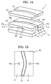
- FIGS. 1A and 1B are views showing a schematic configuration of a press-forming tool according to a first embodiment of the present invention.
- FIG. 1A is a perspective view showing the entirety thereof and
- FIG. 1B is a plan view of a punch configuring the press-forming tool.
- a reference numeral 1 indicates the press-forming tool according to the present embodiment.
- the press-forming tool 1 includes a punch 10, a die 20, and wrinkle suppression molds 25a and 25b.
- the punch 10 includes a punch portion 12 and a plate portion 14 configured to transfer a shape to a blank material.
- the punch portion 12 and the plate portion 14 are fixed to each other by a fastening member (not shown) and become the punch 10.
- the punch portion 12 and the plate portion 14 may integrally form the punch 10.
- wrinkle suppression force increasing portions 16a and 16b are disposed on a surface of the plate portion 14 opposing the wrinkle suppression molds 25a and 25b.
- the wrinkle suppression force increasing portions 16a and 16b protrude toward the wrinkle suppression molds 25a and 25b and generate a reaction force in a direction opposite to a pressing direction when the wrinkle suppression force increasing portions are pressed in the pressing direction in the end phase of press forming.
- the die 20 is paired with the punch 10 and is disposed so as to oppose the punch portion 12.
- the wrinkle suppression molds 25a and 25b are disposed between the punch 10 and the die 20.
- the wrinkle suppression molds 25a and 25b according to the present embodiment are constituted of the minimum number of components, which is difficult to divide it further, from the viewpoint of a structure of a press mold and a shape of a press-formed product. That is to say, the wrinkle suppression molds 25a and 25b are not split-type wrinkle suppression molds but integral-type wrinkle suppression molds.
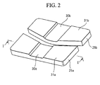
- the wrinkle suppression molds 25a and 25b include first surfaces 31a and 31b which oppose the plate portion 14 of the punch 10 and which come into contact with the plate portion 14 at a press-forming ending point.
- the wrinkle suppression molds 25a and 25b include second surfaces 32a and 32b which oppose the die 20 and which hold the blank material along with the die 20.
- a side surface (third surface) 33a which is continuous between the first surface 31a and the second surface 32a oppose the punch portion 12 via a predetermined gap (clearance).
- a side surface (third surface) 33b which is continuous between the first surface 31b and the second surface 32b oppose the punch portion 12 via a predetermined gap (clearance).
- FIG. 2 is a perspective view when the wrinkle suppression molds 25a and 25b are viewed from the first surfaces 31a and 31b sides.
- the wrinkle suppression molds 25a and 25b include pressure receiving portions (groove portions) 30a and 30b, which receive the reaction force to elastically deform the wrinkle suppression molds 25a and 25b in the end phase of the press forming, on the first surfaces 31 a and 31 b.
- each of the pressure receiving portions 30a and 30b is formed of a groove portion.
- the wrinkle suppression force increasing portions 16a and 16b come into contact with the pressure receiving portions 30a and 30b and are pressed in the pressing direction. If the reaction force is generated in a direction opposite to the pressing direction, the wrinkle suppression molds 25a and 25b receive the reaction force and are elastically deformed.
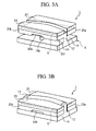
- FIGS. 3A and 3B are explanatory views schematically showing the movements of the punch 10, the die 20, and the wrinkle suppression molds 25a and 25b when the blank material 5 is press-formed.
- FIG. 3A is a perspective view when the press forming starts
- FIG. 3B is a perspective view during the press forming.
- a blank material 5 is disposed on the second surfaces 32a and 32b of the wrinkle suppression molds 25a and 25b in a state where the second surfaces 32a and 32b of the wrinkle suppression molds 25a and 25b and a tip surface 13 of the punch portion 12 are flush with each other.
- the die 20 is lowered in the pressing direction, and a flange portion of the blank material 5 is held by a constant load by the die 20 and the wrinkle suppression molds 25a and 25b.
- the die 20 moves in the pressing direction, that is to say, a direction of the plate portion 14 of the punch 10 (downward in FIG. 3B ), and thus, the press forming of the blank material 5 is performed by the punch portion 12.
- the reaction force in the direction opposite to the pressing direction is generated from the wrinkle suppression force increasing portions 16a and 16b.
- the pressure receiving portions 30a and 30b receive the reaction force, and the wrinkle suppression force with respect to the blank material 5 in the end phase of the press forming is increased.
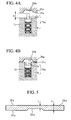
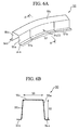
- FIGS. 4A and 4B are vertical cross-sectional views showing when a plurality of disc springs overlap with each other as the wrinkle suppression force increasing portions.
- FIG. 4A shows a state where the wrinkle suppression force is not increased
- FIG. 4B shows a state where the wrinkle suppression force is increased.
- the wrinkle suppression force increasing portion 16a includes a pin 40a and a disc spring 42a.
- the wrinkle suppression force increasing portion 16a includes an elastic body which applies the reaction force.
- 12 disc springs 42a pile in parallel and in series.
- the number and arrangement of the disc springs 42a are not limited to this.
- 4 disc springs 42a may pile in series.
- the wrinkle suppression force increasing portion 16b is similar to the above-described configuration.
- an elastic body such as a helical spring or a rubber may be used. It is preferable that the disc spring 42a is used since it is possible to obtain a high load even by a low stroke.
- the pressure receiving portion 30a provided on the first surface 31 a of the wrinkle suppression mold 25 a presses the pin 40a in the pressing direction, and thus, the disc spring 42a is compressed.
- the wrinkle suppression mold 25a receives the reaction force in the direction opposite to the pressing direction from the disc spring 42a.
- the reaction force is transmitted to the blank material 5 which is held between the second surface 32a of the wrinkle suppression mold 25a and the die 20, and thus, the wrinkle suppression force with respect to the blank material 5 can be increased in the end phase of the press forming.
- the wrinkle suppression mold 25a which receives the reaction force from the disc spring 42a includes the pressure receiving portion 30a which is constituted of a groove portion, and thus, the wrinkle suppression mold 25a is convexly and elastically deformed to the blank material 5 side and is bent. That is to say, when viewed along the pressing direction, a portion which is convexly and elastically deformed on the second surface 32a corresponding to the pressure receiving portion 30a effectively transmits the reaction force to the blank material 5.
- the pressure receiving portion 30a is formed on the first surface 31a of the wrinkle suppression mold 25a.
- the wrinkle suppression mold 25a does not include the pressure receiving portion 30a, the reaction force from the disc spring 42a is distributed to the entire wrinkle suppression mold 25a. Accordingly, since the reaction force cannot be locally applied to the blank material 5, the transmission efficiency of the reaction force is decreased.
- FIG. 5 is a view explaining a thickness of the wrinkle suppression mold 25a, and is a vertical cross-sectional view when the wrinkle suppression mold 25a is viewed from an arrow I direction shown in FIG. 2 .
- the thickness of the wrinkle suppression mold 25a on the pressure receiving portion 30a which is constituted of a groove portion is defined as L in mm units.
- the thickness of the wrinkle suppression mold 25a on the region which excludes the pressure receiving portion 30a and which comes into contact with the blank material 5 is defined as H in mm units.
- the thickness H is constant.
- the minimum value of the thickness on the region which excludes the pressure receiving portion 30a and comes into contact with the blank material 5 may be set to H.
- the thickness H is not constant, there is a case where a press-formed product in which the height of the flange surface is not constant is formed, as shown in FIG. 27 .
- the lower limit of the thickness L is preferably set to 20 mm. If the thickness L is less than 20 mm, the wrinkle suppression mold 25a may be plastically deformed or damaged during drawing and bending processing (during press forming).
- the upper limit of the thickness L is preferably set to 0.8 ⁇ H. If the thickness L exceeds 0.8 ⁇ H, even when the pressure receiving portion 30a receives the reaction force from the wrinkle suppression force increasing portion 16a, the wrinkle suppression mold 25a is not elastically deformed, and thus, the reaction force may not be effectively transmitted to the blank material 5.
- the preferable upper limit of the thickness L is 0.6 ⁇ H. If the upper limit of the thickness L is 0.6 ⁇ H, even when capability of the wrinkle suppression force increasing portion 16a is small, the reaction force generated by the wrinkle suppression force increasing portion 16a can be effectively transmitted to the blank material 5.
- the upper limit of the thickness L is preferably set to 40 mm regardless of the thickness H.
- the maximum value of the reaction force, which is received from the wrinkle suppression force increasing portion 16a to the pressure receiving portion 30a, is 6.5 MPa. Accordingly, if the thickness L exceeds 40 mm, stiffness of the pressure receiving portion 30a is increased, and the wrinkle suppression mold 25 may not be elastically deformed even by the maximum value of the reaction force.
- the stiffness of the entire wrinkle suppression mold 25a is not sufficient.
- the stiffness of the wrinkle suppression mold 25a is increased more than necessary, and a material cost of the wrinkle suppression mold 25a is also increased.
- a relationship between the thickness L and the thickness H preferably satisfies the relationship of the following Expression 1 or 2.
- the wrinkle suppression mold 25b is also similar to the above. 20 ⁇ L ⁇ 0.8 ⁇ H when 40 ⁇ H ⁇ 50 20 ⁇ L ⁇ 40 when 50 ⁇ H ⁇ 80
- the reaction force from the wrinkle suppression force increasing portion 16a is generated from contacting the pressure receiving portion 30a provided on the wrinkle suppression mold 25a with the pin 40a, until the pressure receiving portion 30a reaches the press-forming ending point.
- the position of contacting the pressure receiving portion 30a provided on the wrinkle suppression mold 25a with the pin 40a may be a predetermined position in the end phase of the press forming.
- the position of contacting the pressure receiving portion 30a with the pin 40a may be controlled by changing the protruding length (height) of the tip of the pin 40a from the surface of the plate 14.
- a protruding height G of the tip of the pin 40a from the surface of the plate 14 may be a height which adds a groove depth (a value which is obtained by subtracting L from H) of the pressure receiving portion 30a which is constituted of a groove portion and a distance from the surface of the plate portion 14 to the above-described predetermined position which is added the increased wrinkle suppression force in the end phase of the press forming.
- the protruding height of the tip of the pin 40a of the wrinkle suppression force increasing portion 16a from the surface of the plate 14 is defined as G in mm units.
- a press stroke distance from a press-forming starting point, which is a press stroke position at which the plastic deformation of the blank material 5 starts, to the press-forming ending point is defined as PS in mm units.
- the protruding height G of the wrinkle suppression force increasing portion 16a may preferably satisfy the following Expression 3.
- the wrinkle suppression force increasing portion 16b is also similar to the above. 0.02 ⁇ PS + H - L ⁇ G ⁇ 0.3 ⁇ PS + H - L
- the protruding height G of the pin 40a is preferably equal to or more than a value which adds the groove depth (H-L) of the pressure receiving portion 30a to 2% of the press stroke distance PS (0.02 ⁇ PS). That is to say, the interval of the press stroke which increase the wrinkle suppression force in the end phase of the press forming is preferably equal to or more than 2% of the press stroke distance PS.
- the value of the protruding height G is preferably equal to or more than (0.05 ⁇ PS + H - L).
- the protruding height G of the pin 40a be less than or equal to a value which adds the groove depth (H-L) of the pressure receiving portion 30a to 30% of the press stroke distance PS (0.3 ⁇ PS). That is to say, the interval of the press stroke which increases the wrinkle suppression force in the end phase of the press forming is preferably less than or equal to 30% of the press stroke distance PS.
- the protruding height G exceeds the value (0.3 ⁇ PS + H - L), since the interval of increasing the wrinkle suppression force becomes too long, a difference in the wrinkle suppression force becomes smaller between the press-forming starting point and the press-forming ending point. Accordingly, the effect which is exerted by increasing the wrinkle suppression force is decreased only in the end phase of the press forming is decreased, and thus, the springback may occur to the contrary.
- the value of the protruding height G is preferably less than or equal to (0.15 ⁇ PS + H - L).
- the wrinkle suppression mold 25a and the wrinkle suppression force increasing portion 16a are similar to the above.
- FIGS. 6A and 6B show the press-formed product which is formed by the press-forming tool 1 according to the present embodiment.
- FIG. 6A is a perspective view
- FIG. 6B is a vertical cross-sectional view when viewed from an arrow A direction in FIG. 6A .
- a reference numeral 50 indicates the press-formed product.
- the press-formed product 50 includes flange portions 54a and 54b, vertical wall portions 55a and 55b, and a top portion 55c. Moreover, straight side portions 51 a and 51b and a bent portion 52 interposed between the straight side portions 51a and 51 b are provided on both ends of the press-formed product 50.
- the press-formed product 50 When viewed from the cross section perpendicular to the longitudinal direction, the press-formed product 50 has a so-called hat-shaped cross section, and both ends in the longitudinal direction of the press-formed product 50 are opened.
- the hat-shaped cross section is a shape which includes the top portion 55c provided on the center portion in the width direction, the vertical wall portions 55a and 55b provided to be inclined from both ends of the top portion 55c toward one surface side of the top portion 55c, and the flange portions 54a and 54b provided to be parallel with the top portion 55c from the tips of the vertical wall portions 55a and 55b.
- the non-uniformity of the residual stress for example, springback such as warpage, twist, or waviness of the vertical wall portions 55a and 55b occurs on the press-formed product 50.
- springback such as warpage, twist, or waviness of the vertical wall portions 55a and 55b occurs on the press-formed product 50.
- shrinkage flange deformation or extension flange deformation is applied in the longitudinal direction of the press-formed product 50. Accordingly, the non-uniformity of the residual stress in the plate thickness direction or the in-plane direction is increased.
- finishing processing is performed to the press-formed product 50.
- restriking processing when the press-formed product 50 is processed to the shape of a press-formed product 57 shown in FIGS. 16A and 16B described below, remarkable waviness occurs on the vertical wall portion 55a or the like of the bent portion 52.
- the waviness is generated since the vertical wall portion 55a of the bent portion 52 becomes the extension flange deformation region by the drawing and bending processing (press forming). Accordingly, tensile stress in the longitudinal direction of the press-formed product 50 is increased, and the non-uniformity of the residual stress in the plate thickness direction or the in-plane direction of the press-formed product 50 is promoted.
- the wrinkle suppression force applied to the bent portion 52 is preferably increased in the end phase of the press forming of the draw-bending processing.
- the pressure receiving portion 30a is provided on the wrinkle suppression mold 25a and the pressure receiving portion 30b is provided on the wrinkle suppression mold 25b.
- the wrinkle suppression force increasing portions 16a and 16b are disposed on the plate portion 14.
- the wrinkle suppression force is increased in the end phase of the press forming, and thus, tension of the vertical wall portion 55a of the bent portion 52, which is the region in which the extension flange deformation occurs, is increased. As a result, the non-uniformity of the residual stress in the plate thickness direction or the in-plane direction, which occurs the springback, of the press-formed product 50 is decreased.
- the region in which the shrinkage flange deformation occurs is also similar to the above. That is to say, as described above, the wrinkle suppression force is increased in the end phase of the press forming, and thus, tension of the vertical wall portion 55b of the bent portion 52 which is the region in which the shrinkage flange deformation occurs is also increased. As a result, the springback at the region in which the shrinkage flange deformation occurs is also decreased.
- the wrinkle suppression molds 25a and 25b are not elastically deformed.
- the reaction force from the wrinkle suppression force increasing portions 16a and 16b is distributed on the entire wrinkle suppression molds 25a and 25b. Accordingly, the wrinkle suppression force cannot be locally increased on the bent portion 52 in the end phase of the press forming, and thus, the wrinkle suppression force needed in the bent portion 52 cannot be applied.
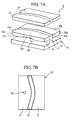
- FIGS. 7A and 7B are views showing a schematic configuration of the press-forming tool according to the second embodiment of the present invention.
- FIG. 7A is a perspective view showing the entirety thereof and
- FIG. 7B is a plan view of a punch configuring the press-forming tool.
- FIG. 8 is a perspective view of a wrinkle suppression mold of the press-forming tool according to the present embodiment when viewed from a first surface side.
- a press-forming tool 2 of the present embodiment is the same as the press-forming tool 1 of the first embodiment except that only the wrinkle suppression force increasing portion 16b is provided on the plate 14, the pressure receiving portion 30b formed of a groove portion is disposed only on the wrinkle suppression mold 25b, and a wrinkle suppression mold 25e does not include the pressure receiving portion.
- the wrinkle suppression force with respect to the blank material 5 can be increased only on the region (only the portion which is particularly added the increased wrinkle suppression force) in which the extension flange deformation occurs. That is to say, when the tensile strength of the blank material 5 is not so high, each of the pressure receiving portion 30b and the wrinkle suppression force increasing portion 16b may be disposed according to curvature or the like of the bent portion 52 of the press-formed product 50.
- FIGS. 9A and 9B are views showing a schematic configuration of the press-forming tool according to the third embodiment of the present invention.
- FIG. 9A is a perspective view showing the entirety thereof and
- FIG. 9B is a plan view of a punch configuring the press-forming tool.
- a press-forming tool 3 according to the present embodiment is the same as the press-forming tool 1 according to the first embodiment except that wrinkle suppression force increasing portions 16a, 16b, 16c, 16d, 16e, and 16f are disposed on the plate portion 14.
- the wrinkle suppression molds 25a and 25b of the press-forming tool 3 according to the present embodiment shown in FIG. 9A are the same as the wrinkle suppression molds 25a and 25b of the press-forming tool 1 according to the first embodiment shown in FIG. 2 .
- the press-forming tool 3 includes the wrinkle suppression force increasing portions 16c to 16f in addition to the wrinkle suppression force increasing portions 16a and 16b which come into contact with the pressure receiving portions 30a and 30b in the end phase of the press forming. Accordingly, it is possible to precisely control the wrinkle suppression force with respect to the blank material 5 in the end phase of the press forming.
- the effect which is exerted by increasing the wrinkle suppression force with respect to the blank material 5 is smaller. That is to say, whether or not disposing the wrinkle suppression force increasing portions 16c to 16f which come into contact with the first surface 31a and 31b, which is not the pressure receiving portions 30a and 30b, may be determined according to the shape of the press-formed product or the structure of the press mold.
- FIGS. 10A and 10B are views showing a schematic configuration of the press-forming tool according to the fourth embodiment of the present invention.
- FIG. 10A is a perspective view showing the entirety thereof and
- FIG. 10B is a plan view of a punch configuring the press-forming tool.
- FIG. 11 is a perspective view when a wrinkle suppression mold of the press-forming tool according to the fourth embodiment is viewed from a first surface side.
- FIG. 12 is a view explaining the wrinkle suppression mold according to the present embodiment and is a vertical cross-sectional view of the wrinkle suppression mold when viewed from an arrow C direction shown in FIG. 11 .
- a press-forming tool 4 according to the present embodiment is the same as the press-forming tool 1 according to the first embodiment except that the pressure receiving portions 30c and 30d of the wrinkle suppression molds 25c and 25d include groove portions 35c and 35d and the groove portions 35c and 35d, become a portion of the boundary portion and partition the pressure receiving portions 30c and 30d.
- the punch 10 according to the present embodiment shown in FIG. 10B is the same as the punch 10 according to the first embodiment.
- the wrinkle suppression molds 25c and 25d according to the present embodiment are constituted of the minimum number of components which is difficult to divide it further, from the viewpoint of the structure of the press mold and the shape of the press-formed product. That is to say, the wrinkle suppression molds 25c and 25d are not split-type wrinkle suppression molds but integral-type wrinkle suppression molds.
- the wrinkle suppression molds 25c and 25d include first surfaces 31c and 31d which oppose the plate portion 14 of the punch 10 and come into contact with the plate portion 14 at the press-forming ending point.
- the wrinkle suppression molds 25c and 25d includes second surfaces 32c and 32d which oppose the die 20 and hold the blank material 5 along with the die 20.
- the pressure receiving portions 30c and 30d which receive the reaction force for elastically deforming the wrinkle suppression molds 25c and 25d in the end phase of the press forming are provided on the first surfaces 31c and 31d.
- the pressure receiving portions 30c and 30d include the groove portions 35c and 35d.
- the groove portions 35c and 35d become a portion of the boundary portion, and the pressure receiving portions 30c and 30d are partitioned on the first surfaces 31 c and 31 d.
- the pressure receiving portions 30c and 30d are partitioned by the groove portions 35c and 35d and partial edges of the first surfaces 31c and 31d on the first surfaces 31c and 31d.
- the pressure receiving portions 30c and 30d and the wrinkle suppression force increasing portions 16a and 16b come into contact with each other, and thus, the wrinkle suppression molds 25c and 25d are elastically deformed. As a result, it is possible to locally add the wrinkle suppression force to the portion of the blank material 5 which is added the increased wrinkle suppression force.
- the wrinkle suppression force in the shrinkage flange deformation region or the extension flange deformation region can be locally increased in the end phase of the press forming, and thus, it is possible to effectively suppress the springback.
- the wrinkle suppression molds 25c and 25d receive the reaction force from the wrinkle suppression force increasing portions 16a and 16b by the pressure receiving portions 30c and 30d, the wrinkle suppression molds 25c and 25d include the groove portions 35c and 35d. Accordingly, the reaction force is not distributed to the entire wrinkle suppression molds 25c and 25d. If the wrinkle suppression molds 25c and 25d receive the reaction force from the wrinkle suppression force increasing portions 16a and 16b, the wrinkle suppression molds 25c and 25d are convexly and elastically deformed to the die 20 (blank material 5) side with the groove portions 35c and 35d as the boundary portion. As a result, it is possible to locally and intensively increase the wrinkle suppression force with respect to the blank material 5.
- the depths, widths, or the like of the groove portions 35c and 35d of the present embodiment are not particularly limited.
- the groove portions 35c and 35d may have appropriate dimensions according to the shape of the press-formed product 50 and the structure of the press mold 4.
- the thickness L of each of the wrinkle suppression mold 25c and 25d in the pressure receiving portions 30c and 30d excluding the groove portions 35c and 35d, and the thickness H of each of the wrinkle suppression mold 25c and 25d in the region which excludes the pressure receiving portions 30c and 30d and comes into contact with the blank material 5 are not particularly limited.
- the thickness L is 20 ⁇ L ⁇ H.
- the protruding height G of each of the wrinkle suppression force increasing portions 16a and 16b is 0.02 ⁇ PS + H - L ⁇ G ⁇ 0.3 ⁇ PS + H - L.
- the press-forming tools 1 to 4 according to the first to fourth embodiments of the present invention are described above. Next, effective positions to dispose the wrinkle suppression force increasing portions 16a to 16f and the pressure receiving portions 30a to 30d will be described.
- FIGS. 13A and 13B are views showing a schematic configuration of a press-forming tool of the related art which does not include the pressure receiving portion and the wrinkle suppression force increasing portion.
- FIG. 13A is a perspective view showing the entirety thereof
- FIG. 13B is a plan view showing a punch configuring the press-forming tool of the related art.
- a reference numeral 91 indicates the press-forming tool of the related art.
- FIG. 14 is an explanatory view showing a plate thickness distribution of a flange portion in a press-formed product when the blank material 5 having the plate thickness of 1.0 mm is performed drawing and bending processing (press-forming) using the press-forming tool of the related art shown in FIG. 13A .
- FIG. 14 is a view showing the state of the press-formed product 50 after the blank material 5 is performed drawing and bending processing (press-forming) using the press-forming tool 91 shown in FIG. 13A , and is plan view when viewed along the pressing direction in a state where the die 20 is omitted.
- the measurement results of the plate thickness of the flange portions 54a and 54b are shown.
- the flange portions 54a and 54b include a curved outside portion 6a, a curved inside portion 6b, and straight line portions 6c, 6d, 6e, and 6f.
- the plate thickness of the curved outside portion 6a is thick.
- the curved outside portion 6a becomes a plate thickness maximum portion in which the plate thickness is the maximum in the flange portions 54a and 54b of the press-formed product 50.
- the plate thickness of the curved inside portion 6b is thin.
- the plate thicknesses in respective portions in the flange portions 54a and 54b are not the same as one another.
- the second surfaces 32e and 32f of wrinkle suppression molds 25e and 25f and the die 20 which hold the blank material 5 are flat.
- the press-forming tool 91 of the related art in which the pressure receiving portions 30a to 30d and the wrinkle suppression force increasing portions 16a to 16f are removed from the press-forming tools 1 to 4 is set as a reference.
- a region in which the plate thickness becomes the maximum in the flange portions 54a and 54b of the press-formed product 50 is defined as a plate thickness maximum portion, and a region in which the plate thickness is more than 0% and less than or equal to 97% with respect to the plate thickness maximum portion is defined as a plate thickness decreasing portion.
- the pressure receiving portions 30a to 30d of the wrinkle suppression molds 25a to 25d are preferably disposed to overlap with a portion of the plate thickness decreasing portion on the blank material 5.
- the wrinkle suppression force at the portion at which the plate thickness in the flange portions 54a and 54b is decreased during the press forming can be preferably increased in the end phase of the press forming.
- the wrinkle suppression force on the plate thickness decreasing portion in which the plate thickness is more than 0% and less than or equal to 97% with respect to the plate thickness maximum portion, is preferably increased in the end phase of the press forming, and thus, the springback of the press-formed product 50 can be effectively decreased.
- FIG. 15 is an explanatory view exemplifying preferable positions at which the pressure receiving portion and the wrinkle suppression force increasing portion are disposed in the view showing the plate thickness distribution of the flange portion in the press-formed product which is formed by the press-forming tool of the related art shown in FIG. 13A . That is to say, as an example, FIG. 15 is an explanatory view in which the disposition positions of the pressure receiving portions 30b and 30d and the wrinkle suppression force increasing portion 16b are overlapped in FIG. 14 .
- the pressure receiving portions 30b and 30d are preferably disposed so that a portion of the curved inside portion 6b (the portion which becomes the plate thickness decreasing portion having the plate thickness of more than 0% and less than or more than 97% with respect to the plate thickness maximum portion) overlaps with the curved outside portion 6a (the portion which becomes the plate thickness maximum portion in the flange portions 54a and 54b of the press-formed product 50 press-formed by the press-forming tool 91 of the related art).
- the wrinkle suppression force increasing portion 16b is preferably disposed such that the wrinkle suppression force increasing portion 16b protrudes toward the pressure receiving portions 30b and 30d, and generate the reaction force opposite to the pressing direction when the wrinkle suppression force increasing portion is pressed in the pressing direction, and elastically deform the wrinkle suppression molds 25b and 25d.
- the wrinkle suppression molds 25b and 25d are convexly and elastically deformed to the blank material 5 side by the pressure receiving portions 30b and 30d in the end phase of the press forming, and thus, it is possible to locally and intensively increase the wrinkle suppression force on the curved inside portion 6b.
- the wrinkle suppression molds 25a to 25d include the first surfaces 31 a to 31d, the second surfaces 32a to 32d, and the side surfaces (third surfaces) 33a and 33b which are continuous between the first surface 31 a to 31 d and the second surface 32a to 32d and which oppose the punch portion 12.
- the wrinkle suppression molds 25a to 25d are disposed between the side surfaces (third surfaces) 33a and 33b and the punch portion 12 via a gap.
- the first surfaces 31a to 31d oppose the plate portion 14 and come into contact with the plate portion 14 at the press-forming ending point.
- the second surfaces 32a to 32d oppose the die 20 and hold the blank material 5 along with the die 20.
- the press-forming tools 1 to 4 include: pressure receiving portions 30a to 30d which include the groove portion, which receives the reaction force to elastically deform the wrinkle suppression molds 25a to 25d in the end phase of the press forming, on the first surfaces 31 a to 31d of the wrinkle suppression molds 25a to 25d; and wrinkle suppression force increasing portions 16a and 16b which are disposed on surfaces opposing the first surfaces 31a to 31d of the plate portion 14, protrude toward the pressure receiving portions 30a to 30d, and generate the reaction force in a direction opposite to the pressing direction when the wrinkle suppression force increasing portions are pressed in the pressing direction in the end phase of press forming.
- a method for manufacturing the press-formed product 50 according to an aspect of the present invention including: a step of increasing the wrinkle suppression force with respect to a portion of the blank material 5 during the press forming in the end phase of the press forming from the position at which the press stroke is 2% to 30% to the forming end position using the press-forming tools 1 to 4 according the above-described aspects, and when the forming start position of the press stroke when the blank material 5 is press-formed is defined as 100% and the forming end position of the press stroke is defined as 0%.
- the springback is suppressed, and thus, the press-formed product 50 having high dimension accuracy can be obtained.
- the position of the press stroke which is a starting position of increasing the wrinkle suppression force is less than 2%, the increase in the wrinkle suppression force is not sufficient, and thus, the effect which is exerted by decreasing the springback may be unstable.
- the position of the press stroke which is a starting position of increasing the wrinkle suppression force is more than 30%, the interval of increasing the wrinkle suppression force becomes too long. Accordingly, the difference in the wrinkle suppression force is decreased between the forming starting position of the press stroke and the forming ending position of the press stork.
- the position of the press stroke which is a starting position of increasing the wrinkle suppression force is preferably 5% to 15%.
- the blank material 5 was obtained by laser-cutting the high tensile strength steel sheet in a predetermined shape.
- the blank material 5 was performed drawing and bending processing (press-forming) so that the shape became a hat-shaped cross section. Moreover, after the drawing and bending processing, the blank material was performed finishing processing (restriking processing). Conditions or the like for each process are described below.
- the high tensile strength steel sheet having 1.0 mm in the plate thickness and 590 MPa in the tensile strength was used as the material, the high tensile strength steel sheet was laser-cut so that the shape after the finishing processing (restriking processing) became a cross-section width of 60 mm and a height of 80 mm as shown in FIGS. 16A and 16B , and thus, the blank material 5 was obtained.
- the blank material 5 was performed drawing and bending processing (press-forming) to have the shape (hat-shaped cross section) shown in FIGS. 6A and 6B using the press-forming tool 1 FIGS. 1A to 2 (the press-forming tool 1 according to the first embodiment), the press-forming tool 2 shown in FIGS. 7A to 8 (the press-forming tool 2 according to the second embodiment), and the press-forming tool 3 shown in FIGS. 9A and 9B (the press-forming tool 3 according to the third embodiment).
- the disc spring unit which is a combination of disc springs 42a shown in FIG. 4A was used.
- the wrinkle suppression force increasing portions 16c to 16f were disposed.
- the thicknesses H of the wrinkle suppression molds 25a and 25b on the region which exclude the pressure receiving portions 30a and 30b and come into contact with the blank material 5 the thicknesses L of the wrinkle suppression molds 25a and 25b on the pressure receiving portion 30a and 30b, and the thickness ratio L/H are shown in Table 1.
- the load (reaction force) of the wrinkle suppression force increasing portions 16a to 16f applied to the wrinkle suppression molds 25a and 25b are also shown in Table 1.
- the load is indicated in the total value of the loads of the disc spring unit disposed on the press-forming tools 1 to 3.
- the press-forming tool 3 shown in FIGS. 9A and 9B was used in the Example of the present invention No. 6.
- the load (reaction force) which is applied to the wrinkle suppression molds 25a and 25b by one disc spring unit in the wrinkle suppression force increasing portions 16a to 16f is 100 kN. Accordingly, the total of the loads (reaction forces) is 600 kN (100 kN ⁇ 6).
- Example No. 14 the press-forming tool 91 shown in FIGS. 13A and 13B , which did not have the pressure receiving portions 30a and 30b and the wrinkle suppression force increasing portions 16a to 16f, was used.
- Reference Example 1 the press-forming tool 1 in which the thickness H and the thickness L of the wrinkle suppression molds 25a and 25b were the same as each other was used.
- the press-forming tool 1 used in the Reference Example 1 was a press-forming tool in which the wrinkle suppression molds 25e and 25f which did not have the pressure receiving portion and the punch 10 which had the wrinkle suppression force increasing portions 16a and 16b were combined.
- Table 1 No. Reference Figure Pressure receiving portion Wrinkle suppression force increasing portion Protrusion height G (mm) Thickness H (mm) Thickness L (mm) L/H (%) Press stroke position which is added increased wrinkle suppression force (%) Remark Position Load (kN) 1 FIGS. 1A to 2 - 16a, 16b 200 (100 ⁇ 2) 9 50 50 100 15 Reference Example 2 FIGS. 1A to 2 30a, 30b 16a, 16b 200 (100 ⁇ 2) 14 50 45 90 15 Reference Example 3 FIGS.
- FIG. 9A and 9B 30a, 30b 16a, 16b, 16c 16d, 16e, 16f 600 (100 ⁇ 6) 19 50 40 80 15
- FIG. 7A to 8 30b 16b 100 (100 ⁇ 1) 34 60 35 58 15
- Example 11 FIG. 1A to 2 30a, 30b 16a, 16b 200 (100 ⁇ 2) 35 50 35 70 33
- Example 12 FIG. 1A to 30a, 30b 16a, 16b 200 (100 ⁇ 2) 16.5 50 35 70 2.5
- Example 13 FIG. 1A to 2 30a, 30b 16a, 16b 200 (100 ⁇ 2) 16.1 50 35 70 1.8
- the drawing and bending processing was performed using a press forming apparatus having a capability of 1960 kN (200 tons). Press forming was performed until the height of the press-formed product 50 became 60 mm as shown in FIG. 6B while 196 kN (20 tons) in the wrinkle suppression load (total value of the loads applied to the wrinkle suppression molds 25a and 25b) was applied. Conventional Example No. 14 was also performed similarly.
- the press forming apparatus used was a general press forming apparatus which did not have a variable die cushion device or the like.
- the increase in the wrinkle suppression force in the end phase of the press forming started from the height of 9 mm before the press-forming ending point. That is to say, the protruding height G of each of the wrinkle suppression force increasing portions 16a and 16b coming into contact with the pressure receiving portions 30a and 30b in the end phase of the press forming was set to the value which added 9 mm to the depth (H-L) of each of the pressure receiving portions 30a and 30b.
- the press stroke distance PS from the press-forming starting point to the press-forming ending point was 60 mm. That is to say, when the forming start position of the press stroke was defined as 100% and the forming end position of the press stroke was defined as 0% during the press-forming of the blank materials, the position of the press stroke which is a starting position of increasing the wrinkle suppression force was positioned at the position of 15%.
- the wrinkle suppression force increasing portions 16a and 16b coming into contact with the pressure receiving portions 30a and 30b in the end phase of the press forming is described.
- the protruding height G was set to 9 mm.
- the increase in the wrinkle suppression force in the end phase of the press forming was controlled as follows. That is to say, as shown in Table 1, the starting position of increasing the wrinkle suppression force was controlled by setting the depth (H-L) of each of the pressure receiving portions 30a and 30b to be constant and changing the value of the protruding height G.
- Example No. 11 of the present invention the increase in the wrinkle suppression force started from the height (the position in which the press stroke is 33%) of 20 mm before the press-forming ending point.
- Example No. 12 of the present invention the increase in the wrinkle suppression force started from the height (the position in which the press stroke is 2.5%) of 1.5 mm before the press-forming ending point.
- Example No. 13 of the present invention the increase in the wrinkle suppression force started from the height (the position in which the press stroke is 1.8%) of 1.1 mm before the press-forming ending point.
- finishing processing was performed using the press-formed product 50 obtained by the above-described drawing and bending processing (press forming).
- FIG. 16A and 16B are views showing the press-formed product after the finishing processing (restriking processing).
- FIG. 16A is a perspective view and FIG. 16B is a vertical cross-sectional view when viewed from an arrow B direction in FIG. 16A .
- a reference numeral 57 indicates the press-formed product after the finishing processing (restriking processing).
- FIG. 17 is a view showing a schematic configuration of a restriking processing mold which performs the finishing processing (restriking processing) and is a perspective view showing the entirety thereof.
- a reference numeral 92 indicates the restriking processing mold.
- the finishing processing was performed using a press-forming apparatus having a capability of 1960 kN (200 tons). As shown in FIG. 16B , the restriking processing was performed until the height of the press-formed product 57 was 80 mm as shown in FIG. 16B . According to the finishing processing (restriking processing), the press-formed product 50 having the hat-shaped cross section became the press-formed product 57 having the shape shown in FIGS. 16A and 16B .
- the press-forming apparatus used was a general press-forming apparatus which did not include the variable die cushion device or the like.
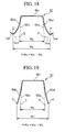
- FIG. 18 is a vertical cross-sectional view perpendicular to a longitudinal direction of the press-formed product after the drawing and bending processing, and an explanatory view showing a generation state of wall warpage (springback).
- W h indicates the gap between the vertical wall portion 55a and the vertical wall portion 55b when the springback is not generated.
- W h ' indicates the gap between the vertical wall portion 55a' and the vertical wall portion 55b' when the springback is generated.
- ⁇ W h indicates the difference between W h ' and W h .
- a line segment PQ is defined as W h .
- a line segment P'Q' is defined as W h '.
- FIG. 19 is a vertical cross-sectional view perpendicular to a longitudinal direction of the press-formed product after the finishing processing (restriking processing), and an explanatory view showing a generation state of wall warpage (springback).
- W c indicates the gap between the vertical wall portion 55a and the vertical wall portion 55b when the springback is not generated.
- W c ' indicates the gap between the vertical wall portion 55a' and the vertical wall portion 55b' when the springback is generated.
- ⁇ W c indicates the difference between W c ' and W c .
- FIG. 20 is a perspective view showing the press-formed product after the finishing processing (restriking processing) and an explanatory view showing a generation state of waviness (springback).
- FIG. 20 a state where waviness 61 occurs on a curved face 60 of the bent portion 52 of the press-formed product 57 is shown.
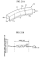
- FIG. 21A is a perspective view showing the press-formed product after the finishing processing (restriking processing) and an explanatory view showing a measurement position of the waviness (springback).
- the generation state of the waviness 61 is evaluated at a line segment 62 shown by a dotted line in FIG. 21A .
- FIG. 21B is a graph showing an example of the measured result of the waviness (springback).
- a horizontal axis corresponds to the line segment 62 shown in FIG. 21A and a vertical axis indicates the generation state (a difference between an actual measured value and a design shape value) of the waviness 61.
- the waviness 61 of the press-formed product 57 may be evaluated as follows. Coordinate values of a point group on the outer surface of the press-formed product after the finishing processing (restriking processing) 57 are acquired using a non-contact type CCD three-dimensional measurement apparatus. The measured results of the coordinate values in the line segment 62 in the curved face 60 are compared with the CAD data (design shape) when the press-formed product 57 is designed, and thus, the graph shown in FIG. 21B is prepared.
- FIG. 21B An absolute value ⁇ Y W of the difference between the maximum value and the minimum value in the graph in the curved face 60 is obtained as shown in FIG. 21B .
- the line segment 62 which is the measurement position of the waviness 61 is parallel with an intersection line formed by the top portion 55c and the vertical wall portion 55a (having a U shaped cross-section) of the press-formed product 57, and the distance between the parallel lines is 70 mm.
- the thickness H and the thickness L preferably satisfy the above-described Expressions 1 and 2.
- the thickness L of each of the wrinkle suppression molds 25a and 25b was changed, and other press-forming conditions were the same as one another.
- the thickness L exceeded 0.8 ⁇ H in No. 1 and No. 2, and the thickness L was less than or equal to 0.8 ⁇ H in No. 3 and No. 4. That is to say, in No. 3 and No. 4 which were examples satisfying Expression 1 or 2 in No. 1 to No. 4, the springback could be preferably decreased.
- FIGS. 22 to 25 show contact pressure distributions on the second surfaces 32a and 32b when the wrinkle suppression molds 25a and 25b receive the reaction force from the wrinkle suppression force increasing portions 16a and 16b in the end phase of the press forming.
- FIGS. 22 to 25 correspond to No. 1 to No. 4 which are the Examples of the present invention and the Reference Examples. That is to say, FIG. 22 shows the contact pressure distribution on the second surface of the wrinkle suppression mold when the thickness ratio L/H of the wrinkle suppression mold is 100%.
- FIG. 23 shows the contact pressure distribution on the second surface of the wrinkle suppression mold when the thickness ratio L/H of the wrinkle suppression mold is 90%.
- FIG. 24 shows the contact pressure distribution on the second surface of the wrinkle suppression mold when the thickness ratio L/H of the wrinkle suppression mold is 80%.
- FIG. 25 shows the contact pressure distribution on the second surface of the wrinkle suppression mold when the thickness ratio L/H of the wrinkle suppression mold is 70%.
- reference numerals 71, 72, 73, and 74 indicate the regions in which the contact pressures on the second surfaces 32a and 32b become the maximum values. Moreover, in the regions of the reference numerals 71, 72, 73, and 74, the contact pressures were 1.5 MPa, 2.5 MPa, 6.5 MPa, and 8.7 MPa, respectively.
- the contact pressures on the regions corresponding to portions on which the pressure receiving portions 30a and 30b are provided on the second surfaces 32a and 32b of the wrinkle suppression molds 25a and 25b are increased as the thickness ratio L/H is decreased.
- the flange portions 54a and 54b of the press-formed product 50 is held between the die 20 and the second surfaces 32a and 32b of the wrinkle suppression molds 25a and 25b, and the wrinkle suppression force is applied to the flange portions.
- the non-uniformity of the residual stress in the plate thickness direction or the in-plane direction of the press-formed product 50 is decreased, and thus, the dimension accuracy of the press-formed product after the finishing processing (restriking processing) 57 is also improved.
- FIG. 26 is a view showing disposed positions of the pressure receiving portion and the wrinkle suppression force increasing portion of the press-forming tool. As shown in FIG. 26 , the disposition positions of the pressure receiving portions 30a, 30b, and 30g to 30j and the wrinkle suppression force increasing portions 16a to 16f were changed, and the blank material 5 was performed the drawing and bending processing (press forming).
- a high tensile strength steel sheet having 1.0 mm in the plate thickness and 590 MPa in the tensile strength was used as the material, and similar to the Example 1, the high tensile strength steel sheet was laser-cut, and thus, the blank material 5 was obtained.
- the blank material 5 was performed the drawing and bending processing (press forming) to have the shape (hat-shaped cross section) shown in FIGS. 6A and 6B .
- Table 3 shows combinations of the disposed positions of the pressure receiving portions 30a, 30b, and 30g to 30j and the wrinkle suppression force increasing portions 16a to 16f.
- the press-forming tool of Example No. 16 of the present invention is the same as the press-forming tool 2 of Example No. 5 of the present invention of the Example 1 except for the thickness H, the thickness L, and the thickness ratio L/H.
- the load (reaction force) applied to the wrinkle suppression molds 25a and 25b by the disc spring unit of the wrinkle suppression force increasing portions 16a to 16f was set to 150 kN. Moreover, the protruding height G was set to 19 mm.
- the press stroke distance PS from the press-forming starting point to the press-forming ending point was set to 60 mm. That is to say, when the forming start position of the press stroke was set to 100% and the forming end position of the press stroke was set to 0% during the press-forming of the blank material 5, the position of the press stroke which is a starting position of increasing the wrinkle suppression force was set to 6.7%.
- FIG. 26 30a 16a 150 (150 ⁇ 1) 19 50 35 70 6.7 Reference Example 16
- Example 17 FIG. 26 30g 16c 150 (150 ⁇ 1) 19 50 35 70 6.7 Reference Example 18
- Example No. 16 of the present invention As shown in Table 4, in Example No. 16 of the present invention, ⁇ W h after the drawing and bending processing, and ⁇ W c and ⁇ Y w after the finishing processing were good, and it could be confirmed that the springback was small.
- Example No. 16 of the present invention the pressure receiving portion 30b was disposed so that the pressure receiving portion overlapped with a portion of the curved inside portion 6b which becomes the plate thickness decreasing portion having the plate thickness more than 0% and less than or equal to 97% with respect to the curved outside portion 6a which becomes the plate thickness maximum portion on the flange portion 54a and 54b of the press-formed product 50 press-formed by the press-forming tool 91 of the related art.
- Example No. 16 of the present invention the wrinkle suppression force could be locally and intensively increased to the curved inside portion 6b which is necessary to increase the wrinkle suppression force in the end phase of the press forming, which was difficult to be achieved by the press-forming tool 91 of the related art.
- Example No. 16 of the present invention ⁇ W h , ⁇ W c , and ⁇ Y w were not better than Example No. 16 of the present invention.
- the pressure receiving portions 30a and 30g to 30j were disposed so that the pressure receiving portions overlapped with not the curved inside portion 6b which becomes the plate thickness decreasing portion but at least a portion of the curved outside portion 6a or the straight line portions 6c to 6f.
- the wrinkle suppression force could not be increased to the curved inside portion 6b which is necessary to increase the wrinkle suppression force in the end phase of the press forming.
- the press-formed product 57 in which the dimensions are outside the permitted range even at one site for example, the press-formed products 57 of the Reference Examples No. 15 and Nos. 17 to 20 are not preferable.
- the wrinkle suppression force on the plate thickness decreasing portion which is necessary to increase the wrinkle suppression force was increased in the end phase of the press forming, it could be confirmed that the dimension accuracy of the press-formed product after the drawing and bending processing 50 and the press-formed product after the finishing processing (restriking processing) 57 could be preferably improved.
- a pressure receiving portion is provided on a portion of a wrinkle suppression mold, and a wrinkle suppression force increasing portion is provided on a portion of a punch.
- the pressure receiving portion and the wrinkle suppression force increasing portion come into contact with each other in the end phase of the press forming, and thus, the wrinkle suppression mold is elastically deformed.
- the wrinkle suppression force generated from the wrinkle suppression force increasing portion is sufficiently transmitted to the portion of a blank material which is added the increased wrinkle suppression force in the end phase of press forming.
Landscapes
- Engineering & Computer Science (AREA)
- Mechanical Engineering (AREA)
- Shaping Metal By Deep-Drawing, Or The Like (AREA)
- Casting Or Compression Moulding Of Plastics Or The Like (AREA)
- Mounting, Exchange, And Manufacturing Of Dies (AREA)
Abstract

Description
- The present invention relates to a press-forming tool for a metal plate, and a method for manufacturing a press-formed product which is press-formed using the press-forming tool. Particularly, the present invention relates to a press-forming tool and a method for manufacturing a press-formed product for securing improved shape freezing properties by decreasing springback which is generated after the press forming is performed.
- It is possible to form members having various shapes by performing press forming using a metal plate such as a steel sheet or aluminum alloy plate. Accordingly, many press-formed products are used in members for an automobile and the like.
- In the press-formed product, there is a problem relating to a dimension accuracy defect (a shape freezing defect) due to an angular change or bending of the press-formed product, which is called springback, generated after the metal plate is press-formed.
- The springback is generated since the press-formed product is deformed by elastic recovery after the press forming due to residual stress introduced into the metal plate during the press forming. When the residual stress introduced into the metal plate is non-uniformly distributed in a plate thickness direction or an in-plane direction of the metal plate, the springback is easily generated.
- In order to decrease the springback and improve the dimension accuracy of the press-formed product, in the end phase of the press forming, it is effective to increase a wrinkle suppression force with respect to a blank material during the press forming.
- However, in order to increase the wrinkle suppression force during the press forming, a press forming apparatus, which includes a variable die cushion device using a servo valve or the like, is generally required.
- With respect to this problem,
Patent Document 1 discloses a press-forming tool in which an elastic body such as a spring is disposed in the press-forming tool. In this press-forming tool, it is possible to increase the wrinkle suppression force in the end phase of the press forming without the variable die cushion device. - Patent Document 2 discloses a press-forming tool in which the disc spring is disposed in the press-forming tool. In this press-forming tool, since the disc spring which can generate a high load even by a low stroke is used, it is possible to make the wrinkle suppression force which is increased in the end phase of the press forming be larger even without the variable die cushion device.
-
Patent Document 3 discloses a press-forming tool in which a wrinkle suppression mold is divided into a corner portion and a straight side portion. In this press-forming tool, it is possible to increase the wrinkle suppression force at every position in which the press forming is performed. -
- [Patent Document 1] Japanese Unexamined Patent Application, First Publication No.
2002-321013 - [Patent Document 2] Japanese Unexamined Patent Application, First Publication No.
2004-344925 - [Patent Document 3] Japanese Unexamined Patent Application, First Publication No.
2003-94119 - In the press-forming tool disclosed in
Patent Document 1, even when the portion which is added an increased the wrinkle suppression force is a part of the entire wrinkle suppression portion, it is necessary to increase the wrinkle suppression force in the entire wrinkle suppression portion. That is to say, in order to suppress the springback of the press-formed product, it is necessary to increase the size of the spring disposed in the press-forming tool or to increase the number of the springs. However, a site capable of disposing the spring in the press-forming tool is limited. Accordingly, when a metal plate having a larger springback such as high tensile strength steel or high tensile strength aluminum alloy is press-formed as the blank material, it is difficult to sufficiently increase the wrinkle suppression force. - In the press-forming tool disclosed in Patent Document 2, as the spring for increasing the wrinkle suppression force, the disc spring capable of obtaining the reaction force of the high load by the low stroke is used. Accordingly, in the end phase of the press forming at which the increase of the wrinkle suppression force is needed, it is possible to effectively increase the wrinkle suppression force by a slight stroke. However, also in this press-forming tool, even when the portion which is added the increased wrinkle suppression force is a part of the entire wrinkle suppression portion, it is also necessary to increase the wrinkle suppression force of the entire wrinkle suppression portion. Therefore, in recent years, when a metal plate which is further high-strengthened is press-formed as the blank material, even if the disc spring is used, the increase of the wrinkle suppression force is not sufficient.
- In the press-forming tool disclosed in
Patent Document 3, in order to suppress occurrence of wrinkles (springback) in the corner portion of the press-formed product which becomes a shrinkage flange deformation region, the wrinkle suppression force in the early phase of the press-forming is increased. In addition, in order to avoid occurrence of breakage in the corner portion, the wrinkle suppression force during the press-forming is decreased. Moreover, in order to remove a shape freezing defect in the corner portion, the wrinkle suppression force is increased again immediately before a bottom dead center (press-forming ending point) of the press-forming. - However, in this press-forming tool, in order to change the wrinkle suppression force in a part of the entire wrinkle suppression portion, the wrinkle suppression mold is set as a split-type. Since the wrinkle suppression mold is the split-type, a large spring force is not required, and only the wrinkle suppression force in the required region is increased.
- However, generally, compared to an integral-type mold, the split mold has many problems with respect to manufacturing, operation, maintenance, repair, replacement, life span, or the like of the mold. Accordingly, since the split mold is adopted, management of the manufacturing process of the press-formed product becomes complicated, and the manufacturing cost of the press-formed product may be increased. Therefore, in a mass production process of press-forming members for an automobile or the like, it is more preferable to change the wrinkle suppression force in a part of the entire wrinkle suppression portion not using the split-type wrinkle suppression mold but using the integral-type wrinkle suppression mold.
- In addition, the integral wrinkle suppression mold refers to a wrinkle suppression mold constituted of the minimum number of components difficult to be further split, from the viewpoint of the manufacturing of the press mold and the shape of the press-formed product.
- Moreover, the press-forming tool disclosed in
Patent Document 3 is a press-forming tool for a drawing of the metal plate and is not suitable to press-form a high-strength metal plate. Specifically, in the press-forming tool disclosed inPatent Document 3, a steel sheet is mainly drawn in a deep cylindrical shape. - Accordingly, the shape of the press-formed product obtained by this press-forming tool is different from the shape of the press-formed product in which the high-strength metal plate is mainly press-formed. In the press mold in which the high-strength metal plate is used as the blank material drawing and bending processing is often performed to obtain a press-formed product in which both ends in the longitudinal direction are opened (hat-shaped cross-section).
- When such the high strength metal plate is performed drawing and bending processing, there are problems which are different from the problems generated when the metal plate is drawn in a deep cylindrical shape.
- In the drawing processing of making the metal plate into a deep cylindrical shape, the drawn corner portion of the press-formed product becomes a shrinkage flange deformation region. On the other hand, in the drawing and bending processing of making the high-strength metal plate into the shape (for example, a member part) having both ends opened in the longitudinal direction, a portion (for example, a flange portion corresponding to an inner side of a bent portion) of the corner portion of the press-formed product becomes an extension flange deformation region.
- Here, the shrinkage flange deformation refers to deformation in which extension and shrinkage are simultaneously generated in two axes an in-plane, and the extension flange deformation refers to deformation in which the extension is generated in both two axes of the in-plane. That is to say, in the press-formed product drawn by the press-forming tool disclosed in
Patent Document 3, the corner portion which becomes the extensions flange deformation region such as the member part does not exist. Moreover, in the drawn press-formed product, the plate thickness of the flange portion at which the shrinkage flange deformation is generated is not changed or is increased. - On the other hand, in the press-formed product after the drawing and bending processing, the plate thickness of the flange portion at which the extension flange deformation is generated is significantly decreased. In the region in which the plate thickness is significantly decreased during the press forming, the wrinkle suppression force is not easily transmitted to the blank material, and as a result, dimension accuracy defects such as wall warpage of the press-formed product or waviness of a vertical wall are easily generated.
- Here, the drawing processing refers to press forming (processing) to obtain a vessel-shaped (cylindrical) press-formed product which does not have the region being generated the extension flange deformation and which does not have opening portions on both ends in a direction perpendicular to an advancement direction (pressing direction) of a punch. Moreover, the drawing and bending processing refers to press forming (processing) to obtain a member-shaped press-formed product which has the region being generated the extension flange deformation and has openings on both ends in the longitudinal direction (the extension direction of the flange portion to which the wrinkle suppression force is applied).
- In the manufacturing process in which the high-strength metal plate is press-formed in a member part or the like, development of a press-forming tool capable of suppressing springback at a portion which becomes the extension flange deformation region in addition to the shrinkage flange deformation region is significantly required.
- In consideration of the above-described circumferences, an object of the present invention is to provide a press-forming tool in which a wrinkle suppression mold is not a split-type but an integral-type and springback can be suppressed in a portion which becomes an extension flange deformation region even when a high-strength metal plate is press-formed as a blank material, and a method for manufacturing a press-formed product which is press-formed using the press-forming tool.
- That is to say, the present invention provides a press-forming tool and a method for manufacturing a press-formed product in which a general press forming apparatus is used without a press forming apparatus having a variable die cushion device, and a press-formed product having high dimension accuracy can be obtained by sufficiently increasing a wrinkle suppression force with respect to a blank material in the end phase of the press forming when a metal plate such as high tensile strength steel or high strength aluminum alloy in which springback easily occurs is press-formed as a blank material.
- Particularly, another object of the present invention is to provide a press-forming tool and a method for manufacturing a press-formed product in which a press-formed product having an extension flange deformation region in addition to a shrinkage flange deformation region can be press-formed with high dimension accuracy by a press-forming tool by which a metal plate is performed drawing and bending processing.
- The inventors earnestly reviewed a mold structure in which a wrinkle suppression force is effectively increased at a portion which is added the increased wrinkle suppression force, in a press-formed product having an extension flange deformation region such as a member part. As a result, the inventors found a providing of a pressure receiving portion on a portion of a wrinkle suppression mold of the press-forming tool and providing of a wrinkle suppression force increasing portion on a portion of a punch of the press-forming tool.
- According to this configuration, in the end phase of the press forming, the pressure receiving portion and the wrinkle suppression force increasing portion come into contact with each other, the wrinkle suppression mold is elastically deformed and bent, and thus, the wrinkle suppression force can be locally added to a portion of the blank material which is added the increased wrinkle suppression force. Springback of a press-formed product having the extension flange deformation region such as a member part can be significantly decreased.
- Here, the part having the extension flange deformation region such as the member part refers to a press-formed product having a hat-shaped cross section shape in which both ends in the longitudinal direction are opened.
- The gist of the present invention is as follows.
- (1) According to an aspect of the present invention, there is provided a press-forming tool comprising: a punch which includes a punch portion and a plate portion which are configured to transfer a shape to a blank material; a die which is paired with the punch and opposes the punch portion; a wrinkle suppression mold which includes a first surface which opposes the plate portion and comes into contact with the plate portion at a press-forming ending point, a second surface which opposes the die and holds the blank material along with the die, and a third surface which is continuous between the first surface and the second surface and opposes the punch portion, and is disposed between the third surface and the punch portion via a gap; a pressure receiving portion which includes a groove portion and which is disposed on the first surface of the wrinkle suppression mold; and a wrinkle suppression force increasing portion which is disposed on the plate portion so as to oppose the first surface, protrudes toward the pressure receiving portion, and generates a reaction force in a direction opposite to a pressing direction when being pressed in the pressing direction in an end phase of a press forming.
- (2) In the press-forming tool according to (1), when a region in which a plate thickness is maximum in a flange portion of a press-formed product is defined as a plate thickness maximum portion and a region in which the plate thickness is more than 0% and less than or equal to 97% with respect to the plate thickness maximum portion is defined as a plate thickness decreasing portion, based on a case where the pressure receiving portion and the wrinkle suppression force increasing portion are removed from the press-forming tool, the pressure receiving portion may overlap with a portion of a region corresponding to the plate thickness decreasing portion in the blank material when viewed along the pressing direction.
- (3) In the press-forming tool according to (1) or (2), the pressure receiving portion is consisted of the groove portion, wherein when a thickness of the wrinkle suppression mold in a position of the groove portion is defined as L in mm units and a minimum value of the thickness of the wrinkle suppression mold in a position which excludes the groove portion and comes into contact with the blank material is defined as H in mm units, the wrinkle suppression mold may satisfy a following
Expression 1 or 2, and when a protruding height of the wrinkle suppression force increasing portion is defined as G in mm units and a press stroke distance from a press-forming starting point to the press-forming ending point is defined as PS in mm units, and the protruding height G of the wrinkle suppression force increasing portion may satisfy a following Expression 3:


- (4) In the press-forming tool according to (1) or (2), a portion of a boundary which partitions the pressure receiving portion may be the groove portion.
- (5) In the press-forming tool according to any one of (1) to (4), the wrinkle suppression force increasing portion may include an elastic body which applies the reaction force.
- (6) In the press-forming tool according to any one of (1) to (5), the elastic body may be at least one of a disc spring, a helical spring, and a rubber.
- (7) According to another aspect of the present invention, there is provided a method for manufacturing a press-formed product which is press-formed using the press-forming tool according to any one of (1) to (6), including a step of increasing a wrinkle suppression force with respect to a portion of a blank material in an end phase of a press forming, which is started from a position at which a press stroke is 2% to 30% and which is ended at a forming end position, when a forming start position of the press stroke is defined as 100% and the forming end position of the press stroke is defined as 0% during the press forming of the blank material.
- According to the above-described aspects of the present invention, a pressure receiving portion is provided on a portion of a wrinkle suppression mold, and a wrinkle suppression force increasing portion is provided on a portion of a punch. The pressure receiving portion and the wrinkle suppression force increasing portion come into contact with each other in the end phase of the press forming, and thus, the wrinkle suppression mold is elastically deformed. As a result, the wrinkle suppression force generated from the wrinkle suppression force increasing portion is sufficiently transmitted to the portion of a blank material which is added the increased wrinkle suppression force in the end phase of press forming.
- That is to say, even when the press-formed product includes an extension flange deformation region in addition to a shrinkage flange deformation region, springback of the press-formed product can be effectively decreased.
- In a press-formed product which is press-formed using a press-forming tool of the related art in which the pressure receiving portion and the wrinkle suppression force increasing portion are removed from the press-forming tool, when a portion in which a plate thickness of a flange portion is thinned is defined as a plate thickness decreasing portion, according to the above-described aspects of the present invention, a portion (a portion which is added an increased the wrinkle suppression force) of a region corresponding to the plate thickness decreasing portion of the blank material and the pressure receiving portion overlap with each other when viewed along the pressing direction.
- Accordingly, the wrinkle suppression force at the portion which is added the increased wrinkle suppression force is preferably increased in the end phase of the press forming. As a result, even when the press-formed product includes the extension flange deformation region in addition to the shrinkage flange deformation region, springback of the press-formed product can be further decreased.
- In addition, according to the above-described aspects of the present invention, even when a metal plate, in which the springback easily occurs, such as high tensile strength steel or high strength aluminum alloy, is used as the blank material, an integral-type wrinkle suppression mold, which is a general press forming apparatus which does not include a variable die cushion device and which is not a split-type is used, and even when the press-formed product includes the extension flange deformation region in addition to the shrinkage flange deformation region, it is possible to obtain a press-formed product having high dimension accuracy.
-
-
FIG. 1A is a view showing a schematic configuration of a press-forming tool according to a first embodiment of the present invention, and is a perspective view showing the entirety thereof. -
FIG. 1B is a plan view of a punch of the press-forming tool according to the first embodiment. -
FIG. 2 is a view showing a wrinkle suppression mold of the press-forming tool according to the first embodiment and is a perspective view when viewed from a first surface side. -
FIG. 3A is an explanatory view schematically showing movements of the punch, a die, and the wrinkle suppression mold when a blank material is press-formed, and is a perspective view when the press forming starts. -
FIG. 3B is an explanatory view schematically showing the movements of the punch, the die, and the wrinkle suppression mold when the blank material is press-formed, and is a perspective view during the press forming. -
FIG. 4A is a view showing a wrinkle suppression force increasing portion of the press-forming tool according to the first embodiment, and a vertical cross-sectional view showing a state where a wrinkle suppression force is not increased when a plurality of disc springs are piled. -
FIG. 4B is a view showing the wrinkle suppression force increasing portion of the press-forming tool according to the first embodiment, and a vertical cross-sectional view showing a state where the wrinkle suppression force is increased when the plurality of disc springs are piled. -
FIG. 5 is a vertical cross-sectional view when viewed from an arrow I direction shown inFIG. 2 . -
FIG. 6A is a perspective view showing a press-formed product which is formed by the press-forming tool according to the first embodiment. -
FIG. 6B is a vertical cross-sectional view when viewed from an arrow A direction inFIG. 6A . -
FIG. 7A is a view showing a schematic configuration of a press-forming tool according to a second embodiment of the present invention, and is a perspective view showing the entirety thereof. -
FIG. 7B is a plan view of a punch of the press-forming tool according to the second embodiment. -
FIG. 8 is a view showing a wrinkle suppression mold of the press-forming tool according to the second embodiment and is a perspective view when viewed from a first surface side. -
FIG. 9A is a view showing a schematic configuration of a press-forming tool according to a third embodiment of the present invention, and is a perspective view showing the entirety thereof. -
FIG. 9B is a plan view of a punch of the press-forming tool according to the third embodiment. -
FIG. 10A is a view showing a schematic configuration of a press-forming tool according to a fourth embodiment of the present invention, and is a perspective view showing the entirety thereof. -
FIG. 10B is a plan view of a punch of the press-forming tool according to the fourth embodiment. -
FIG. 11 is a view showing a wrinkle suppression mold of the press-forming tool according to the fourth embodiment and is a perspective view when viewed from a first surface side. -
FIG. 12 is a vertical cross-sectional view when viewed in an arrow C direction shown inFIG. 11 . -
FIG. 13A is a view showing a schematic configuration of a press-forming tool of the related art which does not include a pressure receiving portion and a wrinkle suppression force increasing portion and is a perspective view showing the entirety thereof. -
FIG. 13B is a plan view showing a punch of the press-forming tool of the related art which does not include the pressure receiving portion and the wrinkle suppression force increasing portion. -
FIG. 14 is an explanatory view showing a plate thickness distribution of a flange portion in a press-formed product which is formed by the press-forming tool of the related art shown inFIG. 13A . -
FIG. 15 is an explanatory view exemplifying positions at which the pressure receiving portion and the wrinkle suppression force increasing portion are disposed in the view showing the plate thickness distribution of the flange portion in the press-formed product which is formed by the press-forming tool of the related art shown inFIG. 13A . -
FIG. 16A is a perspective view showing the press-formed product after the finishing processing (restriking processing). -
FIG. 16B is a vertical cross-sectional view when viewed from an arrow B direction inFIG. 16A . -
FIG. 17 is a view showing a schematic configuration of a restriking processing mold performing the finishing processing (restriking processing) and is a perspective view showing the entirety thereof. -
FIG. 18 is a vertical cross-sectional view perpendicular to a longitudinal direction of the press-formed product which is performed drawing and bending processing, and an explanatory view showing a generation state of wall warpage (springback). -
FIG. 19 is a vertical cross-sectional view perpendicular to the longitudinal direction of the press-formed product after the finishing processing (restriking processing), and an explanatory view showing the generation state of the wall warpage (springback). -
FIG. 20 is a perspective view showing the press-formed product after the finishing processing (restriking processing) and an explanatory view showing a generation state of waviness. -
FIG. 21A is a perspective view showing the press-formed product after the finishing processing (restriking processing) and an explanatory view showing a measurement position of the waviness. -
FIG. 21B is a graph showing an example of the measured result of the waviness in the press-formed product after the finishing processing (restriking processing). -
FIG. 22 is a view showing a contact pressure distribution on a second surface of the wrinkle suppression mold when a thickness ratio L/H of the wrinkle suppression mold is 100%. -
FIG. 23 is a view showing a contact pressure distribution on the second surface of the wrinkle suppression mold when the thickness ratio L/H of the wrinkle suppression mold is 90%. -
FIG. 24 is a view showing a contact pressure distribution on the second surface of the wrinkle suppression mold when the thickness ratio L/H of the wrinkle suppression mold is 80%. -
FIG. 25 is a view showing a contact pressure distribution on the second surface of the wrinkle suppression mold when the thickness ratio L/H of the wrinkle suppression mold is 70%. -
FIG. 26 is a view showing disposed positions of the pressure receiving portion and the wrinkle suppression force increasing portion of the press-forming tool. -
FIG. 27 is a view showing an example of a press-forming tool in which the thickness of the wrinkle suppression mold is not constant, and is a perspective view showing the entirety thereof. - Hereinafter, each embodiment of the present invention will be described in detail with reference to the drawings. However, the present invention is not limited to only the configurations of the following embodiments, and various modifications may be applied to the present invention within a scope which does not depart from the gist of the present invention. Moreover, in the drawings used for the following description, in order to make the description easier to be understood, for convenience, a portion becoming a main portion may be shown to be enlarged, and it is not limited that a dimension ratio of each component or the like is the same as the actual condition.
-
FIGS. 1A and 1B are views showing a schematic configuration of a press-forming tool according to a first embodiment of the present invention.FIG. 1A is a perspective view showing the entirety thereof andFIG. 1B is a plan view of a punch configuring the press-forming tool. InFIG. 1A , areference numeral 1 indicates the press-forming tool according to the present embodiment. - The press-forming
tool 1 according to the present embodiment includes apunch 10, adie 20, andwrinkle suppression molds punch 10 includes apunch portion 12 and aplate portion 14 configured to transfer a shape to a blank material. Thepunch portion 12 and theplate portion 14 are fixed to each other by a fastening member (not shown) and become thepunch 10. Alternatively, thepunch portion 12 and theplate portion 14 may integrally form thepunch 10. - As shown in
FIG. 1B , wrinkle suppressionforce increasing portions plate portion 14 opposing thewrinkle suppression molds force increasing portions wrinkle suppression molds - The
die 20 is paired with thepunch 10 and is disposed so as to oppose thepunch portion 12. Thewrinkle suppression molds punch 10 and thedie 20. Thewrinkle suppression molds wrinkle suppression molds - The
wrinkle suppression molds first surfaces plate portion 14 of thepunch 10 and which come into contact with theplate portion 14 at a press-forming ending point. In addition, thewrinkle suppression molds second surfaces die 20. - A side surface (third surface) 33a which is continuous between the
first surface 31a and thesecond surface 32a oppose thepunch portion 12 via a predetermined gap (clearance). Similarly, a side surface (third surface) 33b which is continuous between thefirst surface 31b and thesecond surface 32b oppose thepunch portion 12 via a predetermined gap (clearance). By setting the gap appropriately, occurrence of wrinkles of the press-formed product or cracks of the press-formed product can be preferably prevented. The setting of the gap may be determined according to a routine procedure. -
FIG. 2 is a perspective view when thewrinkle suppression molds first surfaces FIG. 2 , thewrinkle suppression molds wrinkle suppression molds first surfaces tool 1 according to the present embodiment, each of thepressure receiving portions force increasing portions pressure receiving portions wrinkle suppression molds -
FIGS. 3A and 3B are explanatory views schematically showing the movements of thepunch 10, thedie 20, and thewrinkle suppression molds blank material 5 is press-formed.FIG. 3A is a perspective view when the press forming starts, andFIG. 3B is a perspective view during the press forming. - A
blank material 5 is disposed on thesecond surfaces wrinkle suppression molds second surfaces wrinkle suppression molds tip surface 13 of thepunch portion 12 are flush with each other. - As shown in
FIG. 3A , thedie 20 is lowered in the pressing direction, and a flange portion of theblank material 5 is held by a constant load by thedie 20 and thewrinkle suppression molds - Moreover, as shown in
FIG. 3B , in the state where theblank material 5 is held by thedie 20 and thewrinkle suppression molds plate portion 14 of the punch 10 (downward inFIG. 3B ), and thus, the press forming of theblank material 5 is performed by thepunch portion 12. - At a predetermined position in the end phase of the press forming, the
pressure receiving portions first surfaces wrinkle suppression molds force increasing portions pressure receiving portions force increasing portions - As a result, the reaction force in the direction opposite to the pressing direction is generated from the wrinkle suppression
force increasing portions pressure receiving portions blank material 5 in the end phase of the press forming is increased. -
FIGS. 4A and 4B are vertical cross-sectional views showing when a plurality of disc springs overlap with each other as the wrinkle suppression force increasing portions.FIG. 4A shows a state where the wrinkle suppression force is not increased, andFIG. 4B shows a state where the wrinkle suppression force is increased. - As shown in
FIG. 4A , the wrinkle suppressionforce increasing portion 16a includes apin 40a and adisc spring 42a. In this way, the wrinkle suppressionforce increasing portion 16a includes an elastic body which applies the reaction force. In the present embodiment, 12disc springs 42a pile in parallel and in series. However, the number and arrangement of the disc springs 42a are not limited to this. For example, 4disc springs 42a may pile in series. Although it is not shown, the wrinkle suppressionforce increasing portion 16b is similar to the above-described configuration. - Instead of the
disc spring 42a, an elastic body such as a helical spring or a rubber may be used. It is preferable that thedisc spring 42a is used since it is possible to obtain a high load even by a low stroke. - As shown in
FIG. 4B , thepressure receiving portion 30a provided on thefirst surface 31 a of thewrinkle suppression mold 25 a presses thepin 40a in the pressing direction, and thus, thedisc spring 42a is compressed. Thewrinkle suppression mold 25a receives the reaction force in the direction opposite to the pressing direction from thedisc spring 42a. - As a result, the reaction force is transmitted to the
blank material 5 which is held between thesecond surface 32a of thewrinkle suppression mold 25a and thedie 20, and thus, the wrinkle suppression force with respect to theblank material 5 can be increased in the end phase of the press forming. - The
wrinkle suppression mold 25a which receives the reaction force from thedisc spring 42a includes thepressure receiving portion 30a which is constituted of a groove portion, and thus, thewrinkle suppression mold 25a is convexly and elastically deformed to theblank material 5 side and is bent. That is to say, when viewed along the pressing direction, a portion which is convexly and elastically deformed on thesecond surface 32a corresponding to thepressure receiving portion 30a effectively transmits the reaction force to theblank material 5. Here, thepressure receiving portion 30a is formed on thefirst surface 31a of thewrinkle suppression mold 25a. - If the
wrinkle suppression mold 25a does not include thepressure receiving portion 30a, the reaction force from thedisc spring 42a is distributed to the entirewrinkle suppression mold 25a. Accordingly, since the reaction force cannot be locally applied to theblank material 5, the transmission efficiency of the reaction force is decreased. -
FIG. 5 is a view explaining a thickness of thewrinkle suppression mold 25a, and is a vertical cross-sectional view when thewrinkle suppression mold 25a is viewed from an arrow I direction shown inFIG. 2 . As shown inFIG. 5 , the thickness of thewrinkle suppression mold 25a on thepressure receiving portion 30a which is constituted of a groove portion is defined as L in mm units. Moreover, the thickness of thewrinkle suppression mold 25a on the region which excludes thepressure receiving portion 30a and which comes into contact with theblank material 5 is defined as H in mm units. - In the press-forming
tool 1 according to the present embodiment, the thickness H is constant. However, when the thickness is not constant, the minimum value of the thickness on the region which excludes thepressure receiving portion 30a and comes into contact with theblank material 5 may be set to H. For example, as the case where the thickness H is not constant, there is a case where a press-formed product in which the height of the flange surface is not constant is formed, as shown inFIG. 27 . - The lower limit of the thickness L is preferably set to 20 mm. If the thickness L is less than 20 mm, the
wrinkle suppression mold 25a may be plastically deformed or damaged during drawing and bending processing (during press forming). - On the other hand, in the case of 40 ≤ H ≤ 50, the upper limit of the thickness L is preferably set to 0.8 × H. If the thickness L exceeds 0.8 × H, even when the
pressure receiving portion 30a receives the reaction force from the wrinkle suppressionforce increasing portion 16a, thewrinkle suppression mold 25a is not elastically deformed, and thus, the reaction force may not be effectively transmitted to theblank material 5. - In the case of 40 ≤ H ≤ 50, the preferable upper limit of the thickness L is 0.6 × H. If the upper limit of the thickness L is 0.6 × H, even when capability of the wrinkle suppression
force increasing portion 16a is small, the reaction force generated by the wrinkle suppressionforce increasing portion 16a can be effectively transmitted to theblank material 5. - In the case of 50 < H ≤ 80, the upper limit of the thickness L is preferably set to 40 mm regardless of the thickness H. The maximum value of the reaction force, which is received from the wrinkle suppression
force increasing portion 16a to thepressure receiving portion 30a, is 6.5 MPa. Accordingly, if the thickness L exceeds 40 mm, stiffness of thepressure receiving portion 30a is increased, and the wrinkle suppression mold 25 may not be elastically deformed even by the maximum value of the reaction force. - If the thickness H is less than 40 mm, the stiffness of the entire
wrinkle suppression mold 25a is not sufficient. On the other hand, if the thickness H exceeds 80 mm, the stiffness of thewrinkle suppression mold 25a is increased more than necessary, and a material cost of thewrinkle suppression mold 25a is also increased. - In summary about the thicknesses of the
wrinkle suppression mold 25a, a relationship between the thickness L and the thickness H preferably satisfies the relationship of the followingExpression 1 or 2. Moreover, although it is not shown, thewrinkle suppression mold 25b is also similar to the above.

- The reaction force from the wrinkle suppression
force increasing portion 16a is generated from contacting thepressure receiving portion 30a provided on thewrinkle suppression mold 25a with thepin 40a, until thepressure receiving portion 30a reaches the press-forming ending point. The position of contacting thepressure receiving portion 30a provided on thewrinkle suppression mold 25a with thepin 40a may be a predetermined position in the end phase of the press forming. The position of contacting thepressure receiving portion 30a with thepin 40a may be controlled by changing the protruding length (height) of the tip of thepin 40a from the surface of theplate 14. - As shown in
FIG. 4A , a protruding height G of the tip of thepin 40a from the surface of theplate 14 may be a height which adds a groove depth (a value which is obtained by subtracting L from H) of thepressure receiving portion 30a which is constituted of a groove portion and a distance from the surface of theplate portion 14 to the above-described predetermined position which is added the increased wrinkle suppression force in the end phase of the press forming. - The protruding height of the tip of the
pin 40a of the wrinkle suppressionforce increasing portion 16a from the surface of theplate 14 is defined as G in mm units. A press stroke distance from a press-forming starting point, which is a press stroke position at which the plastic deformation of theblank material 5 starts, to the press-forming ending point is defined as PS in mm units. At this time, the protruding height G of the wrinkle suppressionforce increasing portion 16a may preferably satisfy the followingExpression 3. Moreover, although it is not shown, the wrinkle suppressionforce increasing portion 16b is also similar to the above.
- The protruding height G of the
pin 40a is preferably equal to or more than a value which adds the groove depth (H-L) of thepressure receiving portion 30a to 2% of the press stroke distance PS (0.02 × PS). That is to say, the interval of the press stroke which increase the wrinkle suppression force in the end phase of the press forming is preferably equal to or more than 2% of the press stroke distance PS. - If the protruding height G is less than the value (0.02 × PS + H - L), the increase of the wrinkle suppression force is not sufficient, and the effects which is exerted by decreasing the springback may be unstable. In order to further decrease the springback, the value of the protruding height G is preferably equal to or more than (0.05 × PS + H - L).
- On the other hand, it is preferable that the protruding height G of the
pin 40a be less than or equal to a value which adds the groove depth (H-L) of thepressure receiving portion 30a to 30% of the press stroke distance PS (0.3 × PS). That is to say, the interval of the press stroke which increases the wrinkle suppression force in the end phase of the press forming is preferably less than or equal to 30% of the press stroke distance PS. - If the protruding height G exceeds the value (0.3 × PS + H - L), since the interval of increasing the wrinkle suppression force becomes too long, a difference in the wrinkle suppression force becomes smaller between the press-forming starting point and the press-forming ending point. Accordingly, the effect which is exerted by increasing the wrinkle suppression force is decreased only in the end phase of the press forming is decreased, and thus, the springback may occur to the contrary. In order to further decrease the springback, the value of the protruding height G is preferably less than or equal to (0.15 × PS + H - L).
- So far, it is mainly described regarding the
wrinkle suppression mold 25a and the wrinkle suppressionforce increasing portion 16a. However, thewrinkle suppression mold 25b and the wrinkle suppressionforce increasing portion 16a are similar to the above. -
FIGS. 6A and 6B show the press-formed product which is formed by the press-formingtool 1 according to the present embodiment.FIG. 6A is a perspective view, andFIG. 6B is a vertical cross-sectional view when viewed from an arrow A direction inFIG. 6A . InFIGS. 6A and 6B , areference numeral 50 indicates the press-formed product. - The press-formed
product 50 includesflange portions vertical wall portions top portion 55c. Moreover,straight side portions bent portion 52 interposed between thestraight side portions product 50. - When viewed from the cross section perpendicular to the longitudinal direction, the press-formed
product 50 has a so-called hat-shaped cross section, and both ends in the longitudinal direction of the press-formedproduct 50 are opened. Here, when viewed from an arrow A direction inFIG. 6A , the hat-shaped cross section is a shape which includes thetop portion 55c provided on the center portion in the width direction, thevertical wall portions top portion 55c toward one surface side of thetop portion 55c, and theflange portions top portion 55c from the tips of thevertical wall portions - When the press forming is performed, according to the shape of the press-formed
product 50, it is generated that a portion in which a plastic flow of theblank material 5 is easily occurred and a portion in which the plastic flow is not easily occurred. According to a difference in ease of the generation of the plastic flow, non-uniformity of residual stress in a plate thickness direction or an in-plane direction of the press-formedproduct 50 occurs. - Moreover, due to the non-uniformity of the residual stress, for example, springback such as warpage, twist, or waviness of the
vertical wall portions product 50. Particularly, when the shape of the press-formedproduct 50 has a curved portion, shrinkage flange deformation or extension flange deformation is applied in the longitudinal direction of the press-formedproduct 50. Accordingly, the non-uniformity of the residual stress in the plate thickness direction or the in-plane direction is increased. - In general, after the drawing and bending processing is performed, finishing processing (restriking processing) is performed to the press-formed
product 50. According to the restriking processing, when the press-formedproduct 50 is processed to the shape of a press-formedproduct 57 shown inFIGS. 16A and 16B described below, remarkable waviness occurs on thevertical wall portion 55a or the like of thebent portion 52. - In order to decrease dimension accuracy defects of the press-formed
product 57, in general, an advanced estimation of a deformation amount generated by the springback into mold dimensions at the time of design is often performed. However, when the springback is waviness, it is difficult to estimate the deformation amount in advance. - In addition, since correction of the mold in order to solve the waviness of the press-formed
product 57 includes trial and error, a lot of time and costs are required for the correction of the mold. - The waviness is generated since the
vertical wall portion 55a of thebent portion 52 becomes the extension flange deformation region by the drawing and bending processing (press forming). Accordingly, tensile stress in the longitudinal direction of the press-formedproduct 50 is increased, and the non-uniformity of the residual stress in the plate thickness direction or the in-plane direction of the press-formedproduct 50 is promoted. - Due to the non-uniformity of the residual stress of the press-formed product after drawing and bending
processing 50, waviness occurs on the press-formed product after restrikingprocessing 57. Accordingly, in order to remove the waviness of thebent portion 52, the wrinkle suppression force applied to thebent portion 52 is preferably increased in the end phase of the press forming of the draw-bending processing. - In order to increase the wrinkle suppression force applied to the
bent portion 52 in the end phase of the press forming compared to thestraight side portions FIGS. 1A to 2 , thepressure receiving portion 30a is provided on thewrinkle suppression mold 25a and thepressure receiving portion 30b is provided on thewrinkle suppression mold 25b. In order to elastically deform thewrinkle suppression molds force increasing portions plate portion 14. - As described above, the wrinkle suppression force is increased in the end phase of the press forming, and thus, tension of the
vertical wall portion 55a of thebent portion 52, which is the region in which the extension flange deformation occurs, is increased. As a result, the non-uniformity of the residual stress in the plate thickness direction or the in-plane direction, which occurs the springback, of the press-formedproduct 50 is decreased. - The region in which the shrinkage flange deformation occurs is also similar to the above. That is to say, as described above, the wrinkle suppression force is increased in the end phase of the press forming, and thus, tension of the
vertical wall portion 55b of thebent portion 52 which is the region in which the shrinkage flange deformation occurs is also increased. As a result, the springback at the region in which the shrinkage flange deformation occurs is also decreased. - When the
pressure receiving portions wrinkle suppression molds wrinkle suppression molds force increasing portions wrinkle suppression molds bent portion 52 in the end phase of the press forming, and thus, the wrinkle suppression force needed in thebent portion 52 cannot be applied. - As a result, tension which is necessary to suppress the springback cannot be applied on the
vertical wall portions bent portion 52. Accordingly, effects which is exerted by decreasing the springback of the press-formedproduct 50 are significantly decreased. - In order to decrease the distribution of the reaction force from the above-described wrinkle suppression
force increasing portions force increasing portions disc spring 42a or increase the number of the disc springs 42. In this case, the sizes of the wrinkle suppressionforce increasing portions - On the other hand, in order to press-form a metal plate having a large plastic flow resistance and large springback such as high tensile strength steel or high strength aluminum alloy, since the shape of the press-formed
product 50 is curved, it is particularly necessary to increase the wrinkle suppression force in the end phase of the press forming on the region in which the extension flange deformation or the shrinkage flange deformation occurs, or the like. - Accordingly, when the high tensile strength steel, the high strength aluminum alloy, or the like is press-formed, and in the case of decreasing the distribution of the reaction force by increasing the capability of the wrinkle suppression
force increasing portions force increasing portions force increasing portions tool 1. - Next, a press-forming tool according to a second embodiment of the present invention will be described.
FIGS. 7A and 7B are views showing a schematic configuration of the press-forming tool according to the second embodiment of the present invention.FIG. 7A is a perspective view showing the entirety thereof andFIG. 7B is a plan view of a punch configuring the press-forming tool. -
FIG. 8 is a perspective view of a wrinkle suppression mold of the press-forming tool according to the present embodiment when viewed from a first surface side. - A press-forming tool 2 of the present embodiment is the same as the press-forming
tool 1 of the first embodiment except that only the wrinkle suppressionforce increasing portion 16b is provided on theplate 14, thepressure receiving portion 30b formed of a groove portion is disposed only on thewrinkle suppression mold 25b, and awrinkle suppression mold 25e does not include the pressure receiving portion. - In the press-forming tool 2 according to the present embodiment, the wrinkle suppression force with respect to the
blank material 5 can be increased only on the region (only the portion which is particularly added the increased wrinkle suppression force) in which the extension flange deformation occurs. That is to say, when the tensile strength of theblank material 5 is not so high, each of thepressure receiving portion 30b and the wrinkle suppressionforce increasing portion 16b may be disposed according to curvature or the like of thebent portion 52 of the press-formedproduct 50. - Next, a press-forming tool according to a third embodiment of the present invention will be described.
FIGS. 9A and 9B are views showing a schematic configuration of the press-forming tool according to the third embodiment of the present invention.FIG. 9A is a perspective view showing the entirety thereof andFIG. 9B is a plan view of a punch configuring the press-forming tool. - A press-forming
tool 3 according to the present embodiment is the same as the press-formingtool 1 according to the first embodiment except that wrinkle suppressionforce increasing portions plate portion 14. - Moreover, the
wrinkle suppression molds tool 3 according to the present embodiment shown inFIG. 9A are the same as thewrinkle suppression molds tool 1 according to the first embodiment shown inFIG. 2 . - As shown in
FIGS. 9A and 9B , the press-formingtool 3 according to the present embodiment includes the wrinkle suppressionforce increasing portions 16c to 16f in addition to the wrinkle suppressionforce increasing portions pressure receiving portions blank material 5 in the end phase of the press forming. - However, compared to the wrinkle suppression
force increasing portions pressure receiving portions force increasing portions 16c to 16f which come into contact with thefirst surfaces pressure receiving portions blank material 5 is smaller. That is to say, whether or not disposing the wrinkle suppressionforce increasing portions 16c to 16f which come into contact with thefirst surface pressure receiving portions - Next, a press-forming tool according to a fourth embodiment of the present invention will be described.
FIGS. 10A and 10B are views showing a schematic configuration of the press-forming tool according to the fourth embodiment of the present invention.FIG. 10A is a perspective view showing the entirety thereof andFIG. 10B is a plan view of a punch configuring the press-forming tool. -
FIG. 11 is a perspective view when a wrinkle suppression mold of the press-forming tool according to the fourth embodiment is viewed from a first surface side.FIG. 12 is a view explaining the wrinkle suppression mold according to the present embodiment and is a vertical cross-sectional view of the wrinkle suppression mold when viewed from an arrow C direction shown inFIG. 11 . - A press-forming tool 4 according to the present embodiment is the same as the press-forming
tool 1 according to the first embodiment except that thepressure receiving portions wrinkle suppression molds groove portions groove portions pressure receiving portions - In addition, the
punch 10 according to the present embodiment shown inFIG. 10B is the same as thepunch 10 according to the first embodiment. - The
wrinkle suppression molds wrinkle suppression molds - The
wrinkle suppression molds first surfaces plate portion 14 of thepunch 10 and come into contact with theplate portion 14 at the press-forming ending point. In addition, thewrinkle suppression molds second surfaces blank material 5 along with thedie 20. - In the
wrinkle suppression molds pressure receiving portions wrinkle suppression molds first surfaces pressure receiving portions groove portions groove portions pressure receiving portions first surfaces - Specifically, as shown in
FIG. 11 , thepressure receiving portions groove portions first surfaces first surfaces - In the end phase of the press forming, the
pressure receiving portions force increasing portions wrinkle suppression molds blank material 5 which is added the increased wrinkle suppression force. - Accordingly, the wrinkle suppression force in the shrinkage flange deformation region or the extension flange deformation region can be locally increased in the end phase of the press forming, and thus, it is possible to effectively suppress the springback.
- In the end phase of the press forming, the
wrinkle suppression molds force increasing portions pressure receiving portions wrinkle suppression molds groove portions wrinkle suppression molds wrinkle suppression molds force increasing portions wrinkle suppression molds groove portions blank material 5. - The depths, widths, or the like of the
groove portions groove portions product 50 and the structure of the press mold 4. The thickness L of each of thewrinkle suppression mold pressure receiving portions groove portions wrinkle suppression mold pressure receiving portions blank material 5 are not particularly limited. - In the present embodiment, although it is shown that the aspect in which the thickness L and the thickness H are the same as each other, it is sufficient that the thickness L is 20 ≤ L ≤ H. Moreover, if the thickness L satisfies 20 ≤ L ≤ H, similar to the first embodiment, it is sufficient that the protruding height G of each of the wrinkle suppression
force increasing portions - The press-forming
tools 1 to 4 according to the first to fourth embodiments of the present invention are described above. Next, effective positions to dispose the wrinkle suppressionforce increasing portions 16a to 16f and thepressure receiving portions 30a to 30d will be described. -
FIGS. 13A and 13B are views showing a schematic configuration of a press-forming tool of the related art which does not include the pressure receiving portion and the wrinkle suppression force increasing portion.FIG. 13A is a perspective view showing the entirety thereof, andFIG. 13B is a plan view showing a punch configuring the press-forming tool of the related art. InFIG. 13A , areference numeral 91 indicates the press-forming tool of the related art. -
FIG. 14 is an explanatory view showing a plate thickness distribution of a flange portion in a press-formed product when theblank material 5 having the plate thickness of 1.0 mm is performed drawing and bending processing (press-forming) using the press-forming tool of the related art shown inFIG. 13A . - That is to say,
FIG. 14 is a view showing the state of the press-formedproduct 50 after theblank material 5 is performed drawing and bending processing (press-forming) using the press-formingtool 91 shown inFIG. 13A , and is plan view when viewed along the pressing direction in a state where thedie 20 is omitted. - In
FIG. 14 , the measurement results of the plate thickness of theflange portions FIG. 14 , theflange portions outside portion 6a, a curvedinside portion 6b, andstraight line portions - As shown in
FIG. 14 , the plate thickness of the curvedoutside portion 6a is thick. The curvedoutside portion 6a becomes a plate thickness maximum portion in which the plate thickness is the maximum in theflange portions product 50. On the other hand, the plate thickness of the curved insideportion 6b is thin. - In this way, in the press-formed
product 50 which is press-formed using the press-formingtool 91 of the related art, the plate thicknesses in respective portions in theflange portions wrinkle suppression molds blank material 5 are flat. - Accordingly, in the
wrinkle suppression mold 91 in which thepressure receiving portions 30a to 30d are not provided like thewrinkle suppression molds flange portions - If the magnitude of the wrinkle suppression force is changed according to the portion during the press forming, a balance in the plastic flow of the
blank material 5 during the plastic deformation is lost. As a result, dimension accuracy of the press-formedproduct 50 after the press forming is decreased. - In order to suppress the decrease in the dimension accuracy of the press-formed
product 50 due to the above-described coexistence of the portion to which the wrinkle suppression force is strongly applied and the portion to which the wrinkle suppression force is weakly applied, it is preferable to increase the wrinkle suppression force at the portion at which the plate thickness in theflange portions - Specifically, the press-forming
tool 91 of the related art in which thepressure receiving portions 30a to 30d and the wrinkle suppressionforce increasing portions 16a to 16f are removed from the press-formingtools 1 to 4 is set as a reference. A region in which the plate thickness becomes the maximum in theflange portions product 50 is defined as a plate thickness maximum portion, and a region in which the plate thickness is more than 0% and less than or equal to 97% with respect to the plate thickness maximum portion is defined as a plate thickness decreasing portion. In this case, when viewed along the pressing direction, thepressure receiving portions 30a to 30d of thewrinkle suppression molds 25a to 25d are preferably disposed to overlap with a portion of the plate thickness decreasing portion on theblank material 5. - As a result, the wrinkle suppression force at the portion at which the plate thickness in the
flange portions product 50 can be effectively decreased. -
FIG. 15 is an explanatory view exemplifying preferable positions at which the pressure receiving portion and the wrinkle suppression force increasing portion are disposed in the view showing the plate thickness distribution of the flange portion in the press-formed product which is formed by the press-forming tool of the related art shown inFIG. 13A . That is to say, as an example,FIG. 15 is an explanatory view in which the disposition positions of thepressure receiving portions force increasing portion 16b are overlapped inFIG. 14 . - As shown in
FIG. 15 , thepressure receiving portions portion 6b (the portion which becomes the plate thickness decreasing portion having the plate thickness of more than 0% and less than or more than 97% with respect to the plate thickness maximum portion) overlaps with the curvedoutside portion 6a (the portion which becomes the plate thickness maximum portion in theflange portions product 50 press-formed by the press-formingtool 91 of the related art). - The wrinkle suppression
force increasing portion 16b is preferably disposed such that the wrinkle suppressionforce increasing portion 16b protrudes toward thepressure receiving portions wrinkle suppression molds - As a result, it is possible to preferably increase the wrinkle suppression force of the curved inside
portion 6b in which the plate thickness is decreased in theflange portions - In this way, by disposing the
pressure receiving portions force increasing portions 16b, thewrinkle suppression molds blank material 5 side by thepressure receiving portions portion 6b. - The press-forming tools according to each aspect of the present invention described above are summarized as follows.
- (1) The press-forming
tools 1 to 4 according to each aspect of the present invention include thepunch 10 which includes thepunch portion 12 and theplate portion 14 configured to transfer a shape to theblank material 5, the die 20 which is paired with thepunch 10 and opposes thepunch portion 12, andwrinkle suppression molds 25a to 25d. - The
wrinkle suppression molds 25a to 25d include thefirst surfaces 31 a to 31d, thesecond surfaces 32a to 32d, and the side surfaces (third surfaces) 33a and 33b which are continuous between thefirst surface 31 a to 31 d and thesecond surface 32a to 32d and which oppose thepunch portion 12. Thewrinkle suppression molds 25a to 25d are disposed between the side surfaces (third surfaces) 33a and 33b and thepunch portion 12 via a gap. - The first surfaces 31a to 31d oppose the
plate portion 14 and come into contact with theplate portion 14 at the press-forming ending point. The second surfaces 32a to 32d oppose the die 20 and hold theblank material 5 along with thedie 20. - The press-forming
tools 1 to 4 according to each aspect of the present invention include:pressure receiving portions 30a to 30d which include the groove portion, which receives the reaction force to elastically deform thewrinkle suppression molds 25a to 25d in the end phase of the press forming, on thefirst surfaces 31 a to 31d of thewrinkle suppression molds 25a to 25d; and wrinkle suppressionforce increasing portions first surfaces 31a to 31d of theplate portion 14, protrude toward thepressure receiving portions 30a to 30d, and generate the reaction force in a direction opposite to the pressing direction when the wrinkle suppression force increasing portions are pressed in the pressing direction in the end phase of press forming. - (2) Based on a case where the
pressure receiving portions 30a to 30d and the wrinkle suppressionforce increasing portions tools 1 to 4, the region in which the plate thickness is maximum in theflange portions product 50 is defined as the plate thickness maximum portion. The region in which the plate thickness is more than 0% and less than and equal to 97% with respect to the plate thickness maximum portion is defined as the plate thickness decreasing portion. In this case, thepressure receiving portion 30a to 30d may overlap with a portion of the region corresponding to the plate thickness decreasing portion in theblank material 5 when viewed along the pressing direction. - (3) The
pressure receiving portions wrinkle suppression molds wrinkle suppression molds blank material 5 is defined as H in mm units. In this case, each of thewrinkle suppression molds Expressions 1 and 2, and when the protruding height of each of the wrinkle suppressionforce increasing portions plate portion 14 is defined as G in mm units and the press stroke distance from the press-forming starting point to the press-forming ending point is defined as PS in mm units, the protruding height G of each of the wrinkle suppressionforce increasing portions Expression 3.


- (4) A portion of the boundary which partitions the
pressure receiving portions groove portions pressure receiving portions groove portions groove portions pressure receiving portions first surfaces - (5) The wrinkle suppression
force increasing portions - (6) The elastic body may be at least one of the
disc spring 42a, a helical spring, and rubber. - Next, a method for manufacturing the press-formed
product 50 which is press-formed using the press-formingtools 1 to 4 according to the embodiments of the present invention will be described. - A method for manufacturing the press-formed
product 50 according to an aspect of the present invention, including: a step of increasing the wrinkle suppression force with respect to a portion of theblank material 5 during the press forming in the end phase of the press forming from the position at which the press stroke is 2% to 30% to the forming end position using the press-formingtools 1 to 4 according the above-described aspects, and when the forming start position of the press stroke when theblank material 5 is press-formed is defined as 100% and the forming end position of the press stroke is defined as 0%. - According to the method of manufacturing the press-formed
product 50, the springback is suppressed, and thus, the press-formedproduct 50 having high dimension accuracy can be obtained. In the method for manufacturing, if the position of the press stroke which is a starting position of increasing the wrinkle suppression force is less than 2%, the increase in the wrinkle suppression force is not sufficient, and thus, the effect which is exerted by decreasing the springback may be unstable. - On the other hand, if the position of the press stroke which is a starting position of increasing the wrinkle suppression force is more than 30%, the interval of increasing the wrinkle suppression force becomes too long. Accordingly, the difference in the wrinkle suppression force is decreased between the forming starting position of the press stroke and the forming ending position of the press stork.
- Therefore, the effect which is exerted by increasing the wrinkle suppression force only in the end phase of the press forming is decreased, and thus, the springback may occur to the contrary. Moreover, in order to further decrease the springback, the position of the press stroke which is a starting position of increasing the wrinkle suppression force is preferably 5% to 15%.
- Effects of the aspects of the present invention will be further described according to Examples. However, conditions of Examples are conditions adopted to confirm feasibility and effects of the present invention, and the present invention is not limited to the conditions. The present invention adopts various conditions if achieving the object of the present invention without departing from the gist of the present invention.
- The
blank material 5 was obtained by laser-cutting the high tensile strength steel sheet in a predetermined shape. Theblank material 5 was performed drawing and bending processing (press-forming) so that the shape became a hat-shaped cross section. Moreover, after the drawing and bending processing, the blank material was performed finishing processing (restriking processing). Conditions or the like for each process are described below. - The high tensile strength steel sheet having 1.0 mm in the plate thickness and 590 MPa in the tensile strength was used as the material, the high tensile strength steel sheet was laser-cut so that the shape after the finishing processing (restriking processing) became a cross-section width of 60 mm and a height of 80 mm as shown in
FIGS. 16A and 16B , and thus, theblank material 5 was obtained. - The
blank material 5 was performed drawing and bending processing (press-forming) to have the shape (hat-shaped cross section) shown inFIGS. 6A and 6B using the press-formingtool 1FIGS. 1A to 2 (the press-formingtool 1 according to the first embodiment), the press-forming tool 2 shown inFIGS. 7A to 8 (the press-forming tool 2 according to the second embodiment), and the press-formingtool 3 shown inFIGS. 9A and 9B (the press-formingtool 3 according to the third embodiment). - As the wrinkle suppression
force increasing portions 16a to 16f, the disc spring unit which is a combination of disc springs 42a shown inFIG. 4A was used. The load (reaction force) to which the wrinkle suppressionforce increasing portions 16a to 16f were applied to thewrinkle suppression molds - In the press-forming tool 3 (the press-forming
tool 3 according to the third embodiment) shown inFIGS. 9A and 9B , in addition to thepressure receiving portions force increasing portions 16c to 16f were disposed. - The thicknesses H of the
wrinkle suppression molds pressure receiving portions blank material 5, the thicknesses L of thewrinkle suppression molds pressure receiving portion - The load (reaction force) of the wrinkle suppression
force increasing portions 16a to 16f applied to thewrinkle suppression molds tools 1 to 3. - For example, the press-forming
tool 3 shown inFIGS. 9A and 9B was used in the Example of the present invention No. 6. In this case, six wrinkle suppressionforce increasing portions 16a to 16f are disposed. The load (reaction force) which is applied to thewrinkle suppression molds force increasing portions 16a to 16f is 100 kN. Accordingly, the total of the loads (reaction forces) is 600 kN (100 kN × 6). - In Conventional Example No. 14, the press-forming
tool 91 shown inFIGS. 13A and 13B , which did not have thepressure receiving portions force increasing portions 16a to 16f, was used. In Reference Example 1, the press-formingtool 1 in which the thickness H and the thickness L of thewrinkle suppression molds - That is to say, the press-forming
tool 1 used in the Reference Example 1 was a press-forming tool in which thewrinkle suppression molds punch 10 which had the wrinkle suppressionforce increasing portions [Table 1] No. Reference Figure Pressure receiving portion Wrinkle suppression force increasing portion Protrusion height G (mm) Thickness H (mm) Thickness L (mm) L/H (%) Press stroke position which is added increased wrinkle suppression force (%) Remark Position Load (kN) 1 FIGS. 1A to 2 - 16a, 16b 200 (100×2) 9 50 50 100 15 Reference Example 2 FIGS. 1A to 2 30a, 30b 16a, 16b 200 (100×2) 14 50 45 90 15 Reference Example 3 FIGS. 1A to 2 30a, 30b 16a, 16b 200 (100×2) 19 50 40 80 15 Example 4 FIGS. 1A to 2 30a, 30b 16a, 16b 200 (100×2) 24 50 35 70 15 Example 5 FIGS. 7A to 8 30b 16b 100 (100×1) 19 50 40 80 15 Example 6 FIG. 9A and 9B 30a, 30b 16a, 16b, 16c 600 (100×6) 19 50 40 80 15 Example 7 FIG. 7A to 8 30b 16b 100 (100×1) 21 40 28 70 15 Example 8 FIG. 7A to 8 30b 16b 100 (100×1) 30 70 49 70 15 Reference Example 9 FIG. 7A to 8 30b 16b 100 (100×1) 39 70 40 57 15 Example 10 FIG. 7A to 8 30b 16b 100 (100×1) 34 60 35 58 15 Example 11 FIG. 1A to 2 30a, 30b 16a, 16b 200 (100×2) 35 50 35 70 33 Example 12 FIG. 1A to30a, 30b 16a, 16b 200 (100×2) 16.5 50 35 70 2.5 Example 13 FIG. 1A to 2 30a, 30b 16a, 16b 200 (100×2) 16.1 50 35 70 1.8 Reference Example 14 FIG. 13A and 13B - - - - 50 50 100 0 Conventional Example - The drawing and bending processing (press forming) was performed using a press forming apparatus having a capability of 1960 kN (200 tons). Press forming was performed until the height of the press-formed
product 50 became 60 mm as shown inFIG. 6B while 196 kN (20 tons) in the wrinkle suppression load (total value of the loads applied to thewrinkle suppression molds - The press forming apparatus used was a general press forming apparatus which did not have a variable die cushion device or the like.
- In No. 1 to No. 10 in the Examples of the present invention and the Reference Examples, the increase in the wrinkle suppression force in the end phase of the press forming started from the height of 9 mm before the press-forming ending point. That is to say, the protruding height G of each of the wrinkle suppression
force increasing portions pressure receiving portions pressure receiving portions - The press stroke distance PS from the press-forming starting point to the press-forming ending point was 60 mm. That is to say, when the forming start position of the press stroke was defined as 100% and the forming end position of the press stroke was defined as 0% during the press-forming of the blank materials, the position of the press stroke which is a starting position of increasing the wrinkle suppression force was positioned at the position of 15%.
- Here, the wrinkle suppression
force increasing portions pressure receiving portions force increasing portions 16c to 16f which did not come into contact with thepressure receiving portions - In No. 11 to No. 13 in the Examples of the present invention and the Reference Examples, the increase in the wrinkle suppression force in the end phase of the press forming was controlled as follows. That is to say, as shown in Table 1, the starting position of increasing the wrinkle suppression force was controlled by setting the depth (H-L) of each of the
pressure receiving portions - In Example No. 11 of the present invention, the increase in the wrinkle suppression force started from the height (the position in which the press stroke is 33%) of 20 mm before the press-forming ending point. In Example No. 12 of the present invention, the increase in the wrinkle suppression force started from the height (the position in which the press stroke is 2.5%) of 1.5 mm before the press-forming ending point. In Example No. 13 of the present invention, the increase in the wrinkle suppression force started from the height (the position in which the press stroke is 1.8%) of 1.1 mm before the press-forming ending point.
- The finishing processing (restriking processing) was performed using the press-formed
product 50 obtained by the above-described drawing and bending processing (press forming). -
FIG. 16A and 16B are views showing the press-formed product after the finishing processing (restriking processing).FIG. 16A is a perspective view andFIG. 16B is a vertical cross-sectional view when viewed from an arrow B direction inFIG. 16A . InFIGS. 16A and 16B , areference numeral 57 indicates the press-formed product after the finishing processing (restriking processing). -
FIG. 17 is a view showing a schematic configuration of a restriking processing mold which performs the finishing processing (restriking processing) and is a perspective view showing the entirety thereof. InFIG. 17 , areference numeral 92 indicates the restriking processing mold. - In the press-formed
product 50 obtained by the drawing and bending processing (press forming), a hat portion surrounded by thevertical wall portions top portion 55c was fitted into thepunch portion 12 of therestriking processing mold 92, and thetop portion 55c was pressed by apad 18. The finishing processing (restriking processing) was performed by thepunch portion 12 and thedie 20. In the finishing processing (restriking processing), the wrinkle suppression was not performed. - The finishing processing (restriking processing) was performed using a press-forming apparatus having a capability of 1960 kN (200 tons). As shown in
FIG. 16B , the restriking processing was performed until the height of the press-formedproduct 57 was 80 mm as shown inFIG. 16B . According to the finishing processing (restriking processing), the press-formedproduct 50 having the hat-shaped cross section became the press-formedproduct 57 having the shape shown inFIGS. 16A and 16B . - The press-forming apparatus used was a general press-forming apparatus which did not include the variable die cushion device or the like.
- Next, an evaluation method of the springback with respect to the press-formed
product 50 after the drawing and bending processing and the press-formed product after the finishing processing (restriking processing) 57 will be described. -
FIG. 18 is a vertical cross-sectional view perpendicular to a longitudinal direction of the press-formed product after the drawing and bending processing, and an explanatory view showing a generation state of wall warpage (springback). InFIG. 18 , Wh indicates the gap between thevertical wall portion 55a and thevertical wall portion 55b when the springback is not generated. Wh' indicates the gap between thevertical wall portion 55a' and thevertical wall portion 55b' when the springback is generated. ΔWh indicates the difference between Wh' and Wh. - Specifically, as shown in
FIG. 18 , when an intersection point of thevertical wall portion 55a and theflange portion 54a is defined as P and an intersection point of thevertical wall portion 55b and theflange portion 54b is defined as Q, a line segment PQ is defined as Wh. Moreover, when an intersection point of thevertical wall portion 55a' and theflange portion 54a' is defined as P' and an intersection point of thevertical wall portion 55b' and theflange portion 54b' is defined as Q', a line segment P'Q' is defined as Wh'. - Wh', Wh, and ΔWh may be obtained as follows. Coordinate values of a point group on the outer surface of the press-formed
product 50 after the drawing and bending processing are acquired using a non-contact type CCD three-dimensional measurement apparatus. In the cross-sectional view when viewed from the arrow A direction inFIG. 6A , the gap Wh' between thevertical wall portion 55a' and thevertical wall portion 55b' when the springback is generated is measured. The gap Wh' is compared with the gap Wh between thevertical wall portion 55a and thevertical wall portion 55b in CAD data (design shape) when the press-formedproduct 50 is designed. Accordingly, ΔWh = Wh'- Wh is obtained. - Based on ΔWh obtained in the above-described way, the wall warpage (springback) after the drawing and bending processing (press forming) was evaluated according to the following reference.
- Good (G): ΔWh is less than or equal to 10 mm
- Not Bad (NB): ΔWh is more than 10 mm and less than 15 mm
- Bad (B): ΔWh is equal to or more than 15 mm
-
FIG. 19 is a vertical cross-sectional view perpendicular to a longitudinal direction of the press-formed product after the finishing processing (restriking processing), and an explanatory view showing a generation state of wall warpage (springback). InFIG. 19 , Wc indicates the gap between thevertical wall portion 55a and thevertical wall portion 55b when the springback is not generated. Wc' indicates the gap between thevertical wall portion 55a' and thevertical wall portion 55b' when the springback is generated. ΔWc indicates the difference between Wc' and Wc. - Specifically, as shown in
FIG. 19 , when an end of thevertical wall portion 55a is defined as a point R and an end of thevertical wall portion 55b is defined as a point S, the line segment RS becomes Wc. Moreover, when an end of thevertical wall portion 55a' is defined as a point R' and an end of thevertical wall portion 55b' is defined as a point S', the line segment R'S' becomes Wc'. - Wc', Wc, and ΔWc may be obtained as follows. Coordinate values of a point group on the outer surface of the press-formed product after the finishing processing (restriking processing) 57 are acquired using a non-contact type CCD three-dimensional measurement apparatus. In the cross-sectional view when viewed from the arrow B direction in
FIG. 16A , the gap Wc' between thevertical wall portion 55a' and thevertical wall portion 55b' when the springback is generated is measured. The gap Wc' is compared with the gap Wc between thevertical wall portion 55a and thevertical wall portion 55b in CAD data (design shape) when the press-formedproduct 57 is designed. Accordingly, ΔWc = Wc'- Wc is obtained. - Based on ΔWc obtained in the above-described way, the wall warpage (springback) after the finishing processing (restriking processing) was performed was evaluated according to the following reference.
- Good (G): ΔWc is less than or equal to 7 mm
- Not Bad (NB): ΔWc is more than 7 mm and less than 15 mm
- Bad (B): ΔWc is equal to or more than 15 mm
- Moreover,
FIG. 20 is a perspective view showing the press-formed product after the finishing processing (restriking processing) and an explanatory view showing a generation state of waviness (springback). InFIG. 20 , a state wherewaviness 61 occurs on acurved face 60 of thebent portion 52 of the press-formedproduct 57 is shown. -
FIG. 21A is a perspective view showing the press-formed product after the finishing processing (restriking processing) and an explanatory view showing a measurement position of the waviness (springback). The generation state of thewaviness 61 is evaluated at aline segment 62 shown by a dotted line inFIG. 21A . -
FIG. 21B is a graph showing an example of the measured result of the waviness (springback). InFIG. 21B , a horizontal axis corresponds to theline segment 62 shown inFIG. 21A and a vertical axis indicates the generation state (a difference between an actual measured value and a design shape value) of thewaviness 61. - The
waviness 61 of the press-formedproduct 57 may be evaluated as follows. Coordinate values of a point group on the outer surface of the press-formed product after the finishing processing (restriking processing) 57 are acquired using a non-contact type CCD three-dimensional measurement apparatus. The measured results of the coordinate values in theline segment 62 in thecurved face 60 are compared with the CAD data (design shape) when the press-formedproduct 57 is designed, and thus, the graph shown inFIG. 21B is prepared. - An absolute value ΔYW of the difference between the maximum value and the minimum value in the graph in the
curved face 60 is obtained as shown inFIG. 21B . Theline segment 62 which is the measurement position of thewaviness 61 is parallel with an intersection line formed by thetop portion 55c and thevertical wall portion 55a (having a U shaped cross-section) of the press-formedproduct 57, and the distance between the parallel lines is 70 mm. - Based on ΔYw obtained in this way, the waviness 61 (springback) after the finishing processing (restriking processing) was evaluated according to the following reference.
- Very Good (VG): ΔYw is less than or equal to 3 mm
- Good (G): ΔYw is more than 3 mm and less than 7 mm
- Not Bad (NB): ΔYw is more than 7 mm and less than 15 mm
- Bad (B): ΔYw is equal to or more than 15 mm
- Evaluation results of the springback with respect to the press-formed
product 50 after the drawing and bending processing and the press-formedproduct 57 after the finishing processing (restriking processing) are shown in Table 2. After performing the drawing and bending processing and the restriking processing, cracks were not confirmed in the press-formedproduct 50 or the press-formedproduct 57 under any conditions.[Table 2] No. Crack Occurrence Springback Remark ΔWh ΔWc ΔYw (mm) Evaluation (mm) Evaluation (mm) Evaluation 1 None 16 B 13 NB 14 NB Reference Example 2 None 13 NB 10 NB 8 NB Reference Example 3 None 7 G 5 G 5 G Example 4 None 6 G 4 G 4 G Example 5 None 10 G 7 G 7 G Example 6 None 9 G 7 G 7 G Example 7 None 5 G 5 G 5 G Example 8 None 10 NB 9 NB 8 NB Reference Example 9 None 5 G 4 G 4 G Example 10 None 5 G 3 G 3 VG Example 11 None 8 G 6 G 5 G Example 12 None 9 G 7 G 5 G Example 13 None 18 B 14 NB 16 B Reference Example 14 None 21 B 15 B 18 B Conventional Example - First, the evaluation result of the springback with respect to the press-formed
product 50 after the drawing and bending processing is described. As shown in Table 2, in any one of the Examples No. 3 to No. 7 and No. 9 to No. 12 of the present invention, it was confirmed that ΔWh after the drawing-bending processing was performed was good and the wall warpage (springback) was small. - On the other hand, in any one of Reference Examples No. 1, No. 2, No. 8, and No. 13, and Conventional Example No. 14, ΔWh after the drawing and bending processing was performed was not better than ΔWh of the Example of the present invention.
- By comparing the Examples No. 3 and No. 6 of the present invention, when only the wrinkle suppression
force increasing portions force increasing portions 16a to 16f were disposed. That is to say, when only the wrinkle suppressionforce increasing portions wrinkle suppression molds force increasing portions 16c to 16f are disposed. - As a result, it could be confirmed that the springback in the press-formed
product 50 could be further decreased. - By comparing No. 1 to No. 4 in the Examples of the present invention and the Reference Examples, it could be confirmed that the thickness H and the thickness L preferably satisfy the above-described
Expressions 1 and 2. In No. 1 to No. 4, only the thickness L of each of thewrinkle suppression molds - In No. 1 to No. 4, the values of the protruding heights G were different from one another. However, above all, the position of the press stroke which is a starting position of increasing the wrinkle suppression force was 15% in these Examples, which was the same as one another.
- Among No. 1 to No. 4, the thickness L exceeded 0.8 × H in No. 1 and No. 2, and the thickness L was less than or equal to 0.8 × H in No. 3 and No. 4. That is to say, in No. 3 and No. 4 which were
examples satisfying Expression 1 or 2 in No. 1 to No. 4, the springback could be preferably decreased. - Here,
FIGS. 22 to 25 show contact pressure distributions on thesecond surfaces wrinkle suppression molds force increasing portions -
FIGS. 22 to 25 correspond to No. 1 to No. 4 which are the Examples of the present invention and the Reference Examples. That is to say,FIG. 22 shows the contact pressure distribution on the second surface of the wrinkle suppression mold when the thickness ratio L/H of the wrinkle suppression mold is 100%.FIG. 23 shows the contact pressure distribution on the second surface of the wrinkle suppression mold when the thickness ratio L/H of the wrinkle suppression mold is 90%.FIG. 24 shows the contact pressure distribution on the second surface of the wrinkle suppression mold when the thickness ratio L/H of the wrinkle suppression mold is 80%.FIG. 25 shows the contact pressure distribution on the second surface of the wrinkle suppression mold when the thickness ratio L/H of the wrinkle suppression mold is 70%. - In
FIGS. 22 to 25 ,reference numerals second surfaces reference numerals - As shown in
FIGS. 22 to 25 , when the thickness H is 50 mm, the contact pressures on the regions corresponding to portions on which thepressure receiving portions second surfaces wrinkle suppression molds flange portions product 50 is held between the die 20 and thesecond surfaces wrinkle suppression molds - Accordingly, the portion which is particularly added the increased wrinkle suppression force on the
flange portions pressure receiving portions second surfaces - By comparing No. 4, No. 11 to No. 13 which are the Examples of the present invention and the Reference Examples, it could be confirmed that the protruding height G of each of the wrinkle suppression
force increasing portions Expression 3. In No. 4, No. 11 to No. 13, only the position of the press stroke which is a starting position of increasing the wrinkle suppression force is changed by changing the value of the protruding height G, and other press forming conditions are the same as one other. - Among No. 4, No. 11 to No. 13, in No. 11, the position of the press stroke which is a starting position of increasing the wrinkle suppression force is 33%. In No. 13, the position of the press stroke which is a starting position of increasing the wrinkle suppression force is 1.8%.
- On the other hand, among No. 4, No. 11 to No. 13, in No. 4, the position of the press stroke which is a starting position of increasing the wrinkle suppression force is 15%. In No. 12, the position of the press stroke which is a starting position of increasing the wrinkle suppression force is 2.5%.
- That is to say, among No. 4, No. 11 to No. 13, the protruding height G satisfies
Expression 3 in No. 4 and No. 12. In this way, in No. 4 and No. 12 which are theexamples satisfying Expression 3 among No. 4, No. 11 to No. 13, it could be confirmed that the springback could be preferably decreased. - On the other hand, as described above, in Reference Example No. 1 and No. 2, since the thickness L exceeded 0.8 × H, the springback could not be decreased. In Reference Example No. 8, since the thickness L exceeded 40 mm, the springback could not be decreased.
- As described above, in Reference Example No. 13, since the position of the press stroke which is a starting position of increasing the wrinkle suppression force was 1.8% and the increase of the wrinkle suppression force in the end phase of the press forming was not sufficient, the springback could not be decreased. In Conventional Example No. 14, since the
pressure receiving portions force increasing portions - Next, the evaluation method of the springback with respect to the press-formed product after the finishing processing (restriking processing) 57 will be described. As shown in Table 2, in any one of the Examples No. 3 to No. 7 of the present invention, it could be confirmed that No. 9 to No. 12, ΔWc and ΔYw after the finishing processing (restriking processing) were good and the wall warpage and the
waviness 61 were small. - It could be confirmed that the dimension accuracy of the press-formed product after the finishing processing (restriking processing) 57 was improved as the springback of the press-formed product after the drawing and bending
processing 50 was decreased. This is because the tensile stress in the longitudinal direction of the press-formedproduct 50 on the vertical wall surfaces 55a and 55b of thebent portion 52 is decreased by increasing the wrinkle suppression force of thebent portion 52 in the end phase of the press forming in the drawing and bending processing. - As a result, the non-uniformity of the residual stress in the plate thickness direction or the in-plane direction of the press-formed
product 50 is decreased, and thus, the dimension accuracy of the press-formed product after the finishing processing (restriking processing) 57 is also improved. - On the other hand, in any one of Reference Examples No. 1, No. 2, No, 8, and No. 13 and Conventional Example No. 14, ΔWc and ΔYw after the restriking processing were not better than ΔWc and ΔYw of the Example of the present invention. In this way, if the springback of the press-formed product after the drawing and bending
processing 50 was large, even when the finishing processing (restriking processing) was performed, it could be confirmed that the dimension accuracy of the press-formedproduct 57 was not improved. -
FIG. 26 is a view showing disposed positions of the pressure receiving portion and the wrinkle suppression force increasing portion of the press-forming tool. As shown inFIG. 26 , the disposition positions of thepressure receiving portions force increasing portions 16a to 16f were changed, and theblank material 5 was performed the drawing and bending processing (press forming). - Specifically, a high tensile strength steel sheet having 1.0 mm in the plate thickness and 590 MPa in the tensile strength was used as the material, and similar to the Example 1, the high tensile strength steel sheet was laser-cut, and thus, the
blank material 5 was obtained. Theblank material 5 was performed the drawing and bending processing (press forming) to have the shape (hat-shaped cross section) shown inFIGS. 6A and 6B . - Table 3 shows combinations of the disposed positions of the
pressure receiving portions force increasing portions 16a to 16f. For example, the press-forming tool of Example No. 16 of the present invention is the same as the press-forming tool 2 of Example No. 5 of the present invention of the Example 1 except for the thickness H, the thickness L, and the thickness ratio L/H. - The load (reaction force) applied to the
wrinkle suppression molds force increasing portions 16a to 16f was set to 150 kN. Moreover, the protruding height G was set to 19 mm. The press stroke distance PS from the press-forming starting point to the press-forming ending point was set to 60 mm. That is to say, when the forming start position of the press stroke was set to 100% and the forming end position of the press stroke was set to 0% during the press-forming of theblank material 5, the position of the press stroke which is a starting position of increasing the wrinkle suppression force was set to 6.7%. - After the drawing and bending processing, the finishing processing (restriking processing) was performed. The conditions of the drawing and bending processing, the conditions of the restriking processing, and the evaluation method of the springback were similar to those of the Example 1.
[Table 3] No. Reference figure Pressure receiving portion Wrinkle suppression force increasing portion Protrusion height G (mm) Thickness H (mm) Thickness L (mm) L/H (%) Press Stroke Position which is increased added increased wrinkle suppression force (%) Remark Position Load (kN) 15 FIG. 26 30a 16a 150 (150×1) 19 50 35 70 6.7 Reference Example 16 FIG. 26 30b 16b 150 (150×1) 19 50 35 70 6.7 Example 17 FIG. 26 30g 16c 150 (150×1) 19 50 35 70 6.7 Reference Example 18 FIG. 26 30h 16d 150 (150×1) 19 50 35 70 6.7 Reference Example 19 FIG. 26 30i 16e 150 (150×1) 19 50 35 70 6.7 Reference Example 20 FIG. 26 30j 16f 150 (150×1) 19 50 35 70 6.7 Reference Example - The evaluation results of the springback with respect to the press-formed product after the drawing and bending
processing 50 and the press-formed product after the finishing processing (restriking processing) 57 are shown in Table 4. After the drawing and bending processing and the restriking processing were performed, in any condition, cracks were not confirmed in the press-formedproduct 50 or the press-formedproduct 57.[Table 4] No. Crack Occurrence Springback Remark ΔWh ΔWc ΔYw (mm) Evaluation (mm) Evaluation (mm) Evaluation 15 None 12 NB 10 NB 10 NB Reference Example 16 None 7 G 6 G 6 G Example 17 None 18 B 14 NB 15 B Reference Example 18 None 15 B 12 NB 13 NB Reference Example 19 None 19 B 14 NB 15 B Reference Example 20 None 15 B 12 NB 14 NB Reference Example - As shown in Table 4, in Example No. 16 of the present invention, ΔWh after the drawing and bending processing, and ΔWc and ΔYw after the finishing processing were good, and it could be confirmed that the springback was small.
- In Example No. 16 of the present invention, the
pressure receiving portion 30b was disposed so that the pressure receiving portion overlapped with a portion of the curved insideportion 6b which becomes the plate thickness decreasing portion having the plate thickness more than 0% and less than or equal to 97% with respect to the curvedoutside portion 6a which becomes the plate thickness maximum portion on theflange portion product 50 press-formed by the press-formingtool 91 of the related art. - That is to say, in Example No. 16 of the present invention, the wrinkle suppression force could be locally and intensively increased to the curved inside
portion 6b which is necessary to increase the wrinkle suppression force in the end phase of the press forming, which was difficult to be achieved by the press-formingtool 91 of the related art. - On the other hand, in any one of Reference Example No. 15 and No. 17 to No. 20, ΔWh, ΔWc, and ΔYw were not better than Example No. 16 of the present invention. As shown in Table 4, in Reference Example No. 15 and No. 17 to No. 20, the
pressure receiving portions portion 6b which becomes the plate thickness decreasing portion but at least a portion of the curvedoutside portion 6a or thestraight line portions 6c to 6f. - Accordingly, the wrinkle suppression force could not be increased to the curved inside
portion 6b which is necessary to increase the wrinkle suppression force in the end phase of the press forming. In general, in the press-formedproduct 57, it is required that the dimensions on the entire region of the press-formedproduct 57 are within a permitted range. - That is to say, the press-formed
product 57 in which the dimensions are outside the permitted range even at one site, for example, the press-formedproducts 57 of the Reference Examples No. 15 and Nos. 17 to 20 are not preferable. - As described above, if the wrinkle suppression force on the plate thickness decreasing portion which is necessary to increase the wrinkle suppression force was increased in the end phase of the press forming, it could be confirmed that the dimension accuracy of the press-formed product after the drawing and bending
processing 50 and the press-formed product after the finishing processing (restriking processing) 57 could be preferably improved. - As described above, according to an aspect of the present invention, a pressure receiving portion is provided on a portion of a wrinkle suppression mold, and a wrinkle suppression force increasing portion is provided on a portion of a punch. The pressure receiving portion and the wrinkle suppression force increasing portion come into contact with each other in the end phase of the press forming, and thus, the wrinkle suppression mold is elastically deformed.
- As a result, the wrinkle suppression force generated from the wrinkle suppression force increasing portion is sufficiently transmitted to the portion of a blank material which is added the increased wrinkle suppression force in the end phase of press forming.
- That is to say, even when the press-formed product includes an extension flange deformation region in addition to a shrinkage flange deformation region, springback of the press-formed product can be effectively decreased. Accordingly, the industrial applicability thereof is high.
-
- 1 to 4: press-forming tool
- 5: blank material
- 6a: curved outside portion (plate thickness maximum portion)
- 6b: curved inside portion (plate thickness decreasing portion)
- 6c to 6f: straight line portion
- 10: punch
- 12: punch portion
- 14: plate portion
- 16a to 16f: wrinkle suppression force increasing portion (disc spring unit)
- 20: die
- 25a to 25f: wrinkle suppression mold
- 30a, 30b, and 30g to 30j: pressure receiving portion (groove portion)
- 30c and 30d: pressure receiving portion
- 31 a to 31 f: first surface
- 32a to 32f: second surface
- 33a and 33b: third surface (side surface)
- 35c and 35d: groove portion
- 40a: pin
- 42a: disc spring (elastic body)
- 50: press-formed product after drawing and bending processing
- 51a and 51b: straight side portion
- 52: bent portion
- 54a, 54a', 54b, and 54b': flange portion
- 55a, 55a', 55b, and 55b': vertical wall portion
- 55c: top portion
- 57: press-formed product after the finishing processing (restriking processing)
- 60: curved face
- 61: waviness
- 62: line segment
- G: protruding height
- H and L: thickness
- PS: press stroke distance
Claims (7)
- A press-forming tool comprising:a punch which includes a punch portion and a plate portion which are configured to transfer a shape to a blank material;a die which is paired with the punch and which opposes the punch portion;a wrinkle suppression mold which includes a first surface which opposes the plate portion and which comes into contact with the plate portion at a press-forming ending point, a second surface which opposes the die and which holds the blank material along with the die, and a third surface which is continuous between the first surface and the second surface and which opposes the punch portion, and which is disposed between the third surface and the punch portion via a gap;a pressure receiving portion which includes a groove portion and which is disposed on the first surface of the wrinkle suppression mold; anda wrinkle suppression force increasing portion which is disposed on the plate portion so as to oppose the first surface, which protrudes toward the pressure receiving portion, and which generates a reaction force in a direction opposite to a pressing direction when being pressed in the pressing direction in an end phase of a press forming.
- The press-forming tool according to claim 1,
wherein when a region in which a plate thickness is maximum in a flange portion of a press-formed product is defined as a plate thickness maximum portion and a region in which the plate thickness is more than 0% and less than or equal to 97% with respect to the plate thickness maximum portion is defined as a plate thickness decreasing portion, based on a case where the pressure receiving portion and the wrinkle suppression force increasing portion are removed from the press-forming tool,
the pressure receiving portion overlaps with a portion of a region corresponding to the plate thickness decreasing portion in the blank material when viewed along the pressing direction. - The press-forming tool according to claim 1 or 2,
wherein the pressure receiving portion is consisted of the groove portion, when a thickness of the wrinkle suppression mold in a position of the groove portion is defined as L in mm units and a minimum value of the thickness of the wrinkle suppression mold in a position which excludes the groove portion and comes into contact with the blank material is defined as H in mm units, the wrinkle suppression mold satisfies a following Expression 1 or 2, and
when a protruding height of the wrinkle suppression force increasing portion is defined as G in mm units and a press stroke distance from a press-forming starting point to the press-forming ending point is defined as PS in mm units, and the protruding height G of the wrinkle suppression force increasing portion satisfies a following Expression 3:


- The press-forming tool according to claim 1 or 2,
wherein a portion of a boundary which partitions the pressure receiving portion is the groove portion. - The press-forming tool according to claim 1 or 2,
wherein the wrinkle suppression force increasing portion includes an elastic body which applies the reaction force. - The press-forming tool according to claim 5,
wherein the elastic body is at least one of a disc spring, a helical spring, and a rubber. - A method for manufacturing a press-formed product which is press-formed using the press-forming tool according to claim 1 or 2, comprising:a step of increasing a wrinkle suppression force with respect to a portion of a blank material in an end phase of a press forming, which is started at a position at which a press stroke is 2% to 30% and which is ended at a forming end position, when a forming start position of the press stroke is defined as 100% and the forming end position of the press stroke is defined as 0% during the press forming of the blank material.
Applications Claiming Priority (1)
| Application Number | Priority Date | Filing Date | Title |
|---|---|---|---|
| PCT/JP2012/082907 WO2014097421A1 (en) | 2012-12-19 | 2012-12-19 | Press-forming mold and method for manufacturing press-formed product |
Publications (3)
| Publication Number | Publication Date |
|---|---|
| EP2878392A1 true EP2878392A1 (en) | 2015-06-03 |
| EP2878392A4 EP2878392A4 (en) | 2016-05-11 |
| EP2878392B1 EP2878392B1 (en) | 2017-06-07 |
Family
ID=50977805
Family Applications (1)
| Application Number | Title | Priority Date | Filing Date |
|---|---|---|---|
| EP12890327.5A Active EP2878392B1 (en) | 2012-12-19 | 2012-12-19 | Press-forming mold and method for manufacturing press-formed product |
Country Status (12)
| Country | Link |
|---|---|
| US (1) | US9878362B2 (en) |
| EP (1) | EP2878392B1 (en) |
| JP (1) | JP5783339B2 (en) |
| KR (1) | KR101663433B1 (en) |
| CN (1) | CN104470651B (en) |
| BR (1) | BR112015004208A2 (en) |
| CA (1) | CA2879808C (en) |
| ES (1) | ES2633573T3 (en) |
| IN (1) | IN2015DN00477A (en) |
| MX (1) | MX355006B (en) |
| RU (1) | RU2608866C2 (en) |
| WO (1) | WO2014097421A1 (en) |
Cited By (1)
| Publication number | Priority date | Publication date | Assignee | Title |
|---|---|---|---|---|
| CN108778551A (en) * | 2016-02-23 | 2018-11-09 | 日新制钢株式会社 | Drip molding manufacturing method and its drip molding |
Families Citing this family (16)
| Publication number | Priority date | Publication date | Assignee | Title |
|---|---|---|---|---|
| JP6070066B2 (en) * | 2012-10-30 | 2017-02-01 | Jfeスチール株式会社 | Springback amount evaluation method |
| KR101928686B1 (en) * | 2015-04-22 | 2018-12-12 | 신닛테츠스미킨 카부시키카이샤 | METHOD FOR MANUFACTURING PRESSED MOLD, PRESS MOLD AND PRESS DEVICE |
| BR112017022630A2 (en) * | 2015-04-22 | 2018-07-17 | Nippon Steel & Sumitomo Metal Corporation | The manufacturing method, a press-forming article, a metallic mold, and a press device of a press-forming article |
| CN107225181B (en) * | 2016-03-25 | 2019-08-27 | 宝山钢铁股份有限公司 | A hot stamping die for automobile B-pillar parts without blank holder |
| ES2776885T3 (en) * | 2016-03-28 | 2020-08-03 | Nippon Steel Corp | Method of manufacturing a press-shaped article |
| KR102142092B1 (en) * | 2016-04-27 | 2020-08-06 | 주식회사케이에스엠 | manufacturing method for panel of vehicle using high strength and low specific gravity |
| JP6330930B1 (en) | 2017-01-27 | 2018-05-30 | Jfeスチール株式会社 | Press forming method |
| JP6527544B2 (en) * | 2017-03-28 | 2019-06-05 | Jfeスチール株式会社 | Press forming apparatus and method of manufacturing press formed article |
| CN107081363B (en) * | 2017-04-13 | 2018-11-16 | 西安飞机工业(集团)有限责任公司 | A kind of the sheet metal component rubber pocket manufacturing process and composable mold in the hole containing quadric flanging |
| CN110052522A (en) * | 2019-04-25 | 2019-07-26 | 安徽江淮福臻车体装备有限公司 | A kind of precompressed mechanism metal plate anti-corrugation pressing process and its used |
| TWI890798B (en) * | 2020-06-03 | 2025-07-21 | 日商富士軟片股份有限公司 | Curable resin composition, cured film, laminate, method for producing cured film, and semiconductor device |
| CN112719021B (en) * | 2020-12-11 | 2023-05-23 | 中航贵州飞机有限责任公司 | Flexible side pressing block composite tool for sheet metal part rubber bag forming and use method |
| CN113042637B (en) * | 2021-03-19 | 2023-05-09 | 合肥工业大学 | A multi-point combined limit system and method for sheet metal movement under pressure for correcting molds |
| EP4537952A4 (en) * | 2022-06-06 | 2025-07-02 | Nippon Steel Corp | Pressing device and method for producing a pressed product |
| WO2023238872A1 (en) * | 2022-06-06 | 2023-12-14 | 日本製鉄株式会社 | Pressing device and method for manufacturing pressed product |
| CN117900339A (en) * | 2024-03-20 | 2024-04-19 | 成都长之琳航空制造有限公司 | A fixed groove part processing mold and process |
Family Cites Families (15)
| Publication number | Priority date | Publication date | Assignee | Title |
|---|---|---|---|---|
| SU759177A1 (en) * | 1978-05-31 | 1980-08-30 | За витель | Bending die for producing brackets with bent flanges |
| JPS60191620A (en) | 1984-03-13 | 1985-09-30 | Nissan Motor Co Ltd | press mold |
| RU2057606C1 (en) | 1992-10-20 | 1996-04-10 | Челябинский государственный технический университет | Shape making method |
| JPH06191620A (en) * | 1992-12-24 | 1994-07-12 | Takuo Mori | Scraping device of belt conveyer |
| FR2702401B1 (en) * | 1993-03-09 | 1995-06-16 | Lorraine Laminage | METHOD AND APPARATUS FOR STAMPING METAL BLANKS FOR THE PRODUCTION OF SAID DEEP-PIECE PARTS. |
| JP3622469B2 (en) | 1998-01-28 | 2005-02-23 | 住友金属工業株式会社 | Press molding method and press molding apparatus |
| JP2002219529A (en) * | 2001-01-23 | 2002-08-06 | Toyota Industries Corp | Press die |
| JP3772965B2 (en) | 2001-04-27 | 2006-05-10 | トヨタ自動車株式会社 | Press mold and press working method |
| JP4157286B2 (en) * | 2001-09-25 | 2008-10-01 | 新日本製鐵株式会社 | Press mold |
| JP2004344925A (en) * | 2003-05-22 | 2004-12-09 | Nippon Steel Corp | Press molding die apparatus and press molding method |
| JP5380890B2 (en) | 2008-04-15 | 2014-01-08 | 新日鐵住金株式会社 | Press molding method and apparatus excellent in shape freezing property |
| JP5194982B2 (en) * | 2008-04-15 | 2013-05-08 | 新日鐵住金株式会社 | Press molding method and apparatus excellent in shape freezing property |
| JP5552789B2 (en) | 2009-10-13 | 2014-07-16 | 株式会社Ihi | Die cushion device for press machine |
| JP5626088B2 (en) * | 2010-04-13 | 2014-11-19 | 新日鐵住金株式会社 | Press molding die and press molding method |
| JP5472266B2 (en) * | 2011-11-11 | 2014-04-16 | 新日鐵住金株式会社 | Press molding die and press molding method |
-
2012
- 2012-12-19 MX MX2015002590A patent/MX355006B/en active IP Right Grant
- 2012-12-19 US US14/418,049 patent/US9878362B2/en active Active
- 2012-12-19 JP JP2014552812A patent/JP5783339B2/en active Active
- 2012-12-19 EP EP12890327.5A patent/EP2878392B1/en active Active
- 2012-12-19 CA CA2879808A patent/CA2879808C/en not_active Expired - Fee Related
- 2012-12-19 BR BR112015004208A patent/BR112015004208A2/en active Search and Examination
- 2012-12-19 CN CN201280074661.8A patent/CN104470651B/en active Active
- 2012-12-19 RU RU2015106722A patent/RU2608866C2/en not_active IP Right Cessation
- 2012-12-19 WO PCT/JP2012/082907 patent/WO2014097421A1/en not_active Ceased
- 2012-12-19 ES ES12890327.5T patent/ES2633573T3/en active Active
- 2012-12-19 KR KR1020157000575A patent/KR101663433B1/en active Active
-
2015
- 2015-01-20 IN IN477DEN2015 patent/IN2015DN00477A/en unknown
Cited By (1)
| Publication number | Priority date | Publication date | Assignee | Title |
|---|---|---|---|---|
| CN108778551A (en) * | 2016-02-23 | 2018-11-09 | 日新制钢株式会社 | Drip molding manufacturing method and its drip molding |
Also Published As
| Publication number | Publication date |
|---|---|
| US9878362B2 (en) | 2018-01-30 |
| CA2879808C (en) | 2018-05-01 |
| EP2878392B1 (en) | 2017-06-07 |
| JPWO2014097421A1 (en) | 2017-01-12 |
| CN104470651B (en) | 2016-04-06 |
| EP2878392A4 (en) | 2016-05-11 |
| BR112015004208A2 (en) | 2017-07-04 |
| CA2879808A1 (en) | 2014-06-26 |
| KR101663433B1 (en) | 2016-10-06 |
| IN2015DN00477A (en) | 2015-06-26 |
| CN104470651A (en) | 2015-03-25 |
| KR20150018638A (en) | 2015-02-23 |
| RU2015106722A (en) | 2016-09-20 |
| US20150298197A1 (en) | 2015-10-22 |
| MX2015002590A (en) | 2015-06-10 |
| WO2014097421A1 (en) | 2014-06-26 |
| ES2633573T3 (en) | 2017-09-22 |
| JP5783339B2 (en) | 2015-09-24 |
| RU2608866C2 (en) | 2017-01-25 |
| MX355006B (en) | 2018-03-28 |
Similar Documents
| Publication | Publication Date | Title |
|---|---|---|
| EP2878392B1 (en) | Press-forming mold and method for manufacturing press-formed product | |
| US10286436B2 (en) | Method of press forming and press forming apparatus | |
| EP2578328B1 (en) | Method for forming metal member having excellent shape freezing properties | |
| JP5626088B2 (en) | Press molding die and press molding method | |
| KR101962557B1 (en) | Press forming method and press forming die | |
| WO2011024246A1 (en) | Press forming method | |
| JP2011045905A5 (en) | ||
| EP3272437B1 (en) | Press-forming method and press-forming tool | |
| CN106029248B (en) | The manufacture method and press molding equipment of press-processing method and stamping products | |
| JP4693475B2 (en) | Press molding method and mold used therefor | |
| WO2018180711A1 (en) | Press mold device and production method for press-molded articles | |
| JP2006272413A (en) | Shaping method of curved channel member | |
| KR101591874B1 (en) | Double cross pad of upper die for compensating deformation after stamping automotive structure panel and method thereof | |
| WO2020153500A1 (en) | Press molding method and press machine | |
| JP7099587B1 (en) | Press molding method | |
| JP5472266B2 (en) | Press molding die and press molding method | |
| WO2018180710A1 (en) | Press mold device and production method for press-molded articles | |
| TWI554343B (en) | Press forming die and producing method of pressed products | |
| TWI555592B (en) | Press forming die and producing method of pressed products | |
| JP5332925B2 (en) | Press molding method with excellent dimensional accuracy of molded products | |
| JP2008149351A (en) | Method for press-forming metal sheet |
Legal Events
| Date | Code | Title | Description |
|---|---|---|---|
| PUAI | Public reference made under article 153(3) epc to a published international application that has entered the european phase |
Free format text: ORIGINAL CODE: 0009012 |
|
| 17P | Request for examination filed |
Effective date: 20150209 |
|
| AK | Designated contracting states |
Kind code of ref document: A1 Designated state(s): AL AT BE BG CH CY CZ DE DK EE ES FI FR GB GR HR HU IE IS IT LI LT LU LV MC MK MT NL NO PL PT RO RS SE SI SK SM TR |
|
| AX | Request for extension of the european patent |
Extension state: BA ME |
|
| DAX | Request for extension of the european patent (deleted) | ||
| RA4 | Supplementary search report drawn up and despatched (corrected) |
Effective date: 20160413 |
|
| RIC1 | Information provided on ipc code assigned before grant |
Ipc: B21D 5/01 20060101ALI20160407BHEP Ipc: B21D 22/26 20060101ALI20160407BHEP Ipc: B21D 24/12 20060101AFI20160407BHEP |
|
| GRAP | Despatch of communication of intention to grant a patent |
Free format text: ORIGINAL CODE: EPIDOSNIGR1 |
|
| INTG | Intention to grant announced |
Effective date: 20161216 |
|
| GRAS | Grant fee paid |
Free format text: ORIGINAL CODE: EPIDOSNIGR3 |
|
| AK | Designated contracting states |
Kind code of ref document: B1 Designated state(s): AL AT BE BG CH CY CZ DE DK EE ES FI FR GB GR HR HU IE IS IT LI LT LU LV MC MK MT NL NO PL PT RO RS SE SI SK SM TR |
|
| REG | Reference to a national code |
Ref country code: GB Ref legal event code: FG4D |
|
| GRAA | (expected) grant |
Free format text: ORIGINAL CODE: 0009210 |
|
| REG | Reference to a national code |
Ref country code: CH Ref legal event code: EP Ref country code: AT Ref legal event code: REF Ref document number: 898830 Country of ref document: AT Kind code of ref document: T Effective date: 20170615 |
|
| REG | Reference to a national code |
Ref country code: IE Ref legal event code: FG4D |
|
| REG | Reference to a national code |
Ref country code: DE Ref legal event code: R096 Ref document number: 602012033323 Country of ref document: DE |
|
| REG | Reference to a national code |
Ref country code: ES Ref legal event code: FG2A Ref document number: 2633573 Country of ref document: ES Kind code of ref document: T3 Effective date: 20170922 |
|
| REG | Reference to a national code |
Ref country code: NL Ref legal event code: MP Effective date: 20170607 |
|
| REG | Reference to a national code |
Ref country code: LT Ref legal event code: MG4D |
|
| PG25 | Lapsed in a contracting state [announced via postgrant information from national office to epo] |
Ref country code: LT Free format text: LAPSE BECAUSE OF FAILURE TO SUBMIT A TRANSLATION OF THE DESCRIPTION OR TO PAY THE FEE WITHIN THE PRESCRIBED TIME-LIMIT Effective date: 20170607 Ref country code: FI Free format text: LAPSE BECAUSE OF FAILURE TO SUBMIT A TRANSLATION OF THE DESCRIPTION OR TO PAY THE FEE WITHIN THE PRESCRIBED TIME-LIMIT Effective date: 20170607 Ref country code: NO Free format text: LAPSE BECAUSE OF FAILURE TO SUBMIT A TRANSLATION OF THE DESCRIPTION OR TO PAY THE FEE WITHIN THE PRESCRIBED TIME-LIMIT Effective date: 20170907 Ref country code: GR Free format text: LAPSE BECAUSE OF FAILURE TO SUBMIT A TRANSLATION OF THE DESCRIPTION OR TO PAY THE FEE WITHIN THE PRESCRIBED TIME-LIMIT Effective date: 20170908 Ref country code: HR Free format text: LAPSE BECAUSE OF FAILURE TO SUBMIT A TRANSLATION OF THE DESCRIPTION OR TO PAY THE FEE WITHIN THE PRESCRIBED TIME-LIMIT Effective date: 20170607 |
|
| REG | Reference to a national code |
Ref country code: AT Ref legal event code: MK05 Ref document number: 898830 Country of ref document: AT Kind code of ref document: T Effective date: 20170607 |
|
| PG25 | Lapsed in a contracting state [announced via postgrant information from national office to epo] |
Ref country code: BG Free format text: LAPSE BECAUSE OF FAILURE TO SUBMIT A TRANSLATION OF THE DESCRIPTION OR TO PAY THE FEE WITHIN THE PRESCRIBED TIME-LIMIT Effective date: 20170907 Ref country code: RS Free format text: LAPSE BECAUSE OF FAILURE TO SUBMIT A TRANSLATION OF THE DESCRIPTION OR TO PAY THE FEE WITHIN THE PRESCRIBED TIME-LIMIT Effective date: 20170607 Ref country code: LV Free format text: LAPSE BECAUSE OF FAILURE TO SUBMIT A TRANSLATION OF THE DESCRIPTION OR TO PAY THE FEE WITHIN THE PRESCRIBED TIME-LIMIT Effective date: 20170607 Ref country code: SE Free format text: LAPSE BECAUSE OF FAILURE TO SUBMIT A TRANSLATION OF THE DESCRIPTION OR TO PAY THE FEE WITHIN THE PRESCRIBED TIME-LIMIT Effective date: 20170607 Ref country code: NL Free format text: LAPSE BECAUSE OF FAILURE TO SUBMIT A TRANSLATION OF THE DESCRIPTION OR TO PAY THE FEE WITHIN THE PRESCRIBED TIME-LIMIT Effective date: 20170607 |
|
| REG | Reference to a national code |
Ref country code: FR Ref legal event code: PLFP Year of fee payment: 6 |
|
| PG25 | Lapsed in a contracting state [announced via postgrant information from national office to epo] |
Ref country code: RO Free format text: LAPSE BECAUSE OF FAILURE TO SUBMIT A TRANSLATION OF THE DESCRIPTION OR TO PAY THE FEE WITHIN THE PRESCRIBED TIME-LIMIT Effective date: 20170607 Ref country code: CZ Free format text: LAPSE BECAUSE OF FAILURE TO SUBMIT A TRANSLATION OF THE DESCRIPTION OR TO PAY THE FEE WITHIN THE PRESCRIBED TIME-LIMIT Effective date: 20170607 Ref country code: SK Free format text: LAPSE BECAUSE OF FAILURE TO SUBMIT A TRANSLATION OF THE DESCRIPTION OR TO PAY THE FEE WITHIN THE PRESCRIBED TIME-LIMIT Effective date: 20170607 Ref country code: AT Free format text: LAPSE BECAUSE OF FAILURE TO SUBMIT A TRANSLATION OF THE DESCRIPTION OR TO PAY THE FEE WITHIN THE PRESCRIBED TIME-LIMIT Effective date: 20170607 Ref country code: EE Free format text: LAPSE BECAUSE OF FAILURE TO SUBMIT A TRANSLATION OF THE DESCRIPTION OR TO PAY THE FEE WITHIN THE PRESCRIBED TIME-LIMIT Effective date: 20170607 |
|
| PGFP | Annual fee paid to national office [announced via postgrant information from national office to epo] |
Ref country code: TR Payment date: 20171210 Year of fee payment: 6 |
|
| PG25 | Lapsed in a contracting state [announced via postgrant information from national office to epo] |
Ref country code: IT Free format text: LAPSE BECAUSE OF FAILURE TO SUBMIT A TRANSLATION OF THE DESCRIPTION OR TO PAY THE FEE WITHIN THE PRESCRIBED TIME-LIMIT Effective date: 20170607 Ref country code: PL Free format text: LAPSE BECAUSE OF FAILURE TO SUBMIT A TRANSLATION OF THE DESCRIPTION OR TO PAY THE FEE WITHIN THE PRESCRIBED TIME-LIMIT Effective date: 20170607 Ref country code: IS Free format text: LAPSE BECAUSE OF FAILURE TO SUBMIT A TRANSLATION OF THE DESCRIPTION OR TO PAY THE FEE WITHIN THE PRESCRIBED TIME-LIMIT Effective date: 20171007 Ref country code: SM Free format text: LAPSE BECAUSE OF FAILURE TO SUBMIT A TRANSLATION OF THE DESCRIPTION OR TO PAY THE FEE WITHIN THE PRESCRIBED TIME-LIMIT Effective date: 20170607 |
|
| REG | Reference to a national code |
Ref country code: DE Ref legal event code: R097 Ref document number: 602012033323 Country of ref document: DE |
|
| PLBE | No opposition filed within time limit |
Free format text: ORIGINAL CODE: 0009261 |
|
| STAA | Information on the status of an ep patent application or granted ep patent |
Free format text: STATUS: NO OPPOSITION FILED WITHIN TIME LIMIT |
|
| PG25 | Lapsed in a contracting state [announced via postgrant information from national office to epo] |
Ref country code: DK Free format text: LAPSE BECAUSE OF FAILURE TO SUBMIT A TRANSLATION OF THE DESCRIPTION OR TO PAY THE FEE WITHIN THE PRESCRIBED TIME-LIMIT Effective date: 20170607 |
|
| 26N | No opposition filed |
Effective date: 20180308 |
|
| PG25 | Lapsed in a contracting state [announced via postgrant information from national office to epo] |
Ref country code: SI Free format text: LAPSE BECAUSE OF FAILURE TO SUBMIT A TRANSLATION OF THE DESCRIPTION OR TO PAY THE FEE WITHIN THE PRESCRIBED TIME-LIMIT Effective date: 20170607 |
|
| REG | Reference to a national code |
Ref country code: CH Ref legal event code: PL |
|
| GBPC | Gb: european patent ceased through non-payment of renewal fee |
Effective date: 20171219 |
|
| REG | Reference to a national code |
Ref country code: IE Ref legal event code: MM4A |
|
| PG25 | Lapsed in a contracting state [announced via postgrant information from national office to epo] |
Ref country code: MT Free format text: LAPSE BECAUSE OF NON-PAYMENT OF DUE FEES Effective date: 20171219 Ref country code: LU Free format text: LAPSE BECAUSE OF NON-PAYMENT OF DUE FEES Effective date: 20171219 |
|
| REG | Reference to a national code |
Ref country code: BE Ref legal event code: MM Effective date: 20171231 |
|
| PG25 | Lapsed in a contracting state [announced via postgrant information from national office to epo] |
Ref country code: IE Free format text: LAPSE BECAUSE OF NON-PAYMENT OF DUE FEES Effective date: 20171219 |
|
| PG25 | Lapsed in a contracting state [announced via postgrant information from national office to epo] |
Ref country code: CH Free format text: LAPSE BECAUSE OF NON-PAYMENT OF DUE FEES Effective date: 20171231 Ref country code: BE Free format text: LAPSE BECAUSE OF NON-PAYMENT OF DUE FEES Effective date: 20171231 Ref country code: GB Free format text: LAPSE BECAUSE OF NON-PAYMENT OF DUE FEES Effective date: 20171219 Ref country code: LI Free format text: LAPSE BECAUSE OF NON-PAYMENT OF DUE FEES Effective date: 20171231 |
|
| REG | Reference to a national code |
Ref country code: DE Ref legal event code: R082 Ref document number: 602012033323 Country of ref document: DE Representative=s name: VOSSIUS & PARTNER PATENTANWAELTE RECHTSANWAELT, DE Ref country code: DE Ref legal event code: R081 Ref document number: 602012033323 Country of ref document: DE Owner name: NIPPON STEEL CORPORATION, JP Free format text: FORMER OWNER: NIPPON STEEL & SUMITOMO METAL CORPORATION, TOKYO, JP |
|
| PG25 | Lapsed in a contracting state [announced via postgrant information from national office to epo] |
Ref country code: HU Free format text: LAPSE BECAUSE OF FAILURE TO SUBMIT A TRANSLATION OF THE DESCRIPTION OR TO PAY THE FEE WITHIN THE PRESCRIBED TIME-LIMIT; INVALID AB INITIO Effective date: 20121219 Ref country code: MC Free format text: LAPSE BECAUSE OF FAILURE TO SUBMIT A TRANSLATION OF THE DESCRIPTION OR TO PAY THE FEE WITHIN THE PRESCRIBED TIME-LIMIT Effective date: 20170607 |
|
| PG25 | Lapsed in a contracting state [announced via postgrant information from national office to epo] |
Ref country code: CY Free format text: LAPSE BECAUSE OF FAILURE TO SUBMIT A TRANSLATION OF THE DESCRIPTION OR TO PAY THE FEE WITHIN THE PRESCRIBED TIME-LIMIT Effective date: 20170607 |
|
| PG25 | Lapsed in a contracting state [announced via postgrant information from national office to epo] |
Ref country code: MK Free format text: LAPSE BECAUSE OF FAILURE TO SUBMIT A TRANSLATION OF THE DESCRIPTION OR TO PAY THE FEE WITHIN THE PRESCRIBED TIME-LIMIT Effective date: 20170607 |
|
| PGFP | Annual fee paid to national office [announced via postgrant information from national office to epo] |
Ref country code: ES Payment date: 20200102 Year of fee payment: 8 |
|
| PG25 | Lapsed in a contracting state [announced via postgrant information from national office to epo] |
Ref country code: PT Free format text: LAPSE BECAUSE OF FAILURE TO SUBMIT A TRANSLATION OF THE DESCRIPTION OR TO PAY THE FEE WITHIN THE PRESCRIBED TIME-LIMIT Effective date: 20170607 |
|
| PG25 | Lapsed in a contracting state [announced via postgrant information from national office to epo] |
Ref country code: AL Free format text: LAPSE BECAUSE OF FAILURE TO SUBMIT A TRANSLATION OF THE DESCRIPTION OR TO PAY THE FEE WITHIN THE PRESCRIBED TIME-LIMIT Effective date: 20170607 |
|
| REG | Reference to a national code |
Ref country code: ES Ref legal event code: FD2A Effective date: 20220412 |
|
| PG25 | Lapsed in a contracting state [announced via postgrant information from national office to epo] |
Ref country code: TR Free format text: LAPSE BECAUSE OF NON-PAYMENT OF DUE FEES Effective date: 20201219 |
|
| PG25 | Lapsed in a contracting state [announced via postgrant information from national office to epo] |
Ref country code: ES Free format text: LAPSE BECAUSE OF NON-PAYMENT OF DUE FEES Effective date: 20201220 |
|
| PGFP | Annual fee paid to national office [announced via postgrant information from national office to epo] |
Ref country code: DE Payment date: 20251028 Year of fee payment: 14 |
|
| PGFP | Annual fee paid to national office [announced via postgrant information from national office to epo] |
Ref country code: FR Payment date: 20251110 Year of fee payment: 14 |