EP2878350B1 - Inlet baffle assembly for an in-line interceptor - Google Patents
Inlet baffle assembly for an in-line interceptor Download PDFInfo
- Publication number
- EP2878350B1 EP2878350B1 EP14194010.6A EP14194010A EP2878350B1 EP 2878350 B1 EP2878350 B1 EP 2878350B1 EP 14194010 A EP14194010 A EP 14194010A EP 2878350 B1 EP2878350 B1 EP 2878350B1
- Authority
- EP
- European Patent Office
- Prior art keywords
- section
- inlet baffle
- flow
- flow control
- baffle assembly
- Prior art date
- Legal status (The legal status is an assumption and is not a legal conclusion. Google has not performed a legal analysis and makes no representation as to the accuracy of the status listed.)
- Not-in-force
Links
- 239000004519 grease Substances 0.000 claims description 43
- 239000002351 wastewater Substances 0.000 claims description 36
- 238000004140 cleaning Methods 0.000 claims description 18
- 238000011144 upstream manufacturing Methods 0.000 claims description 12
- 238000000034 method Methods 0.000 claims description 10
- 239000003921 oil Substances 0.000 claims description 9
- 239000000463 material Substances 0.000 claims description 6
- 239000003925 fat Substances 0.000 claims description 5
- 238000007689 inspection Methods 0.000 claims description 4
- 239000012530 fluid Substances 0.000 description 12
- 238000000926 separation method Methods 0.000 description 6
- 235000013305 food Nutrition 0.000 description 5
- 239000010794 food waste Substances 0.000 description 4
- 230000007246 mechanism Effects 0.000 description 4
- 238000002360 preparation method Methods 0.000 description 4
- 239000010865 sewage Substances 0.000 description 4
- 239000002699 waste material Substances 0.000 description 3
- 238000006073 displacement reaction Methods 0.000 description 2
- 230000000717 retained effect Effects 0.000 description 2
- 239000008365 aqueous carrier Substances 0.000 description 1
- 230000000712 assembly Effects 0.000 description 1
- 238000000429 assembly Methods 0.000 description 1
- 230000015572 biosynthetic process Effects 0.000 description 1
- 230000001276 controlling effect Effects 0.000 description 1
- 238000007599 discharging Methods 0.000 description 1
- 239000003897 fog Substances 0.000 description 1
- 230000003993 interaction Effects 0.000 description 1
- 239000007788 liquid Substances 0.000 description 1
- 235000021056 liquid food Nutrition 0.000 description 1
- 230000001105 regulatory effect Effects 0.000 description 1
- 239000007787 solid Substances 0.000 description 1
- 230000003068 static effect Effects 0.000 description 1
- 230000007704 transition Effects 0.000 description 1
- 238000011179 visual inspection Methods 0.000 description 1
- XLYOFNOQVPJJNP-UHFFFAOYSA-N water Substances O XLYOFNOQVPJJNP-UHFFFAOYSA-N 0.000 description 1
Images





Classifications
-
- E—FIXED CONSTRUCTIONS
- E03—WATER SUPPLY; SEWERAGE
- E03F—SEWERS; CESSPOOLS
- E03F5/00—Sewerage structures
- E03F5/14—Devices for separating liquid or solid substances from sewage, e.g. sand or sludge traps, rakes or grates
- E03F5/16—Devices for separating oil, water or grease from sewage in drains leading to the main sewer
-
- B—PERFORMING OPERATIONS; TRANSPORTING
- B01—PHYSICAL OR CHEMICAL PROCESSES OR APPARATUS IN GENERAL
- B01D—SEPARATION
- B01D17/00—Separation of liquids, not provided for elsewhere, e.g. by thermal diffusion
- B01D17/02—Separation of non-miscible liquids
- B01D17/0208—Separation of non-miscible liquids by sedimentation
- B01D17/0211—Separation of non-miscible liquids by sedimentation with baffles
-
- C—CHEMISTRY; METALLURGY
- C02—TREATMENT OF WATER, WASTE WATER, SEWAGE, OR SLUDGE
- C02F—TREATMENT OF WATER, WASTE WATER, SEWAGE, OR SLUDGE
- C02F1/00—Treatment of water, waste water, or sewage
- C02F1/40—Devices for separating or removing fatty or oily substances or similar floating material
-
- C—CHEMISTRY; METALLURGY
- C02—TREATMENT OF WATER, WASTE WATER, SEWAGE, OR SLUDGE
- C02F—TREATMENT OF WATER, WASTE WATER, SEWAGE, OR SLUDGE
- C02F2307/00—Location of water treatment or water treatment device
- C02F2307/08—Treatment of wastewater in the sewer, e.g. to reduce grease, odour
Definitions
- This invention relates generally to the field of wastewater management and in particular to grease interceptors of the type which are used on wastewater outflows from, for example, commercial food establishments.
- Grease interceptors are typically used to prevent fats, oils and grease (“FOG”) from entering the sanitary sewage system.
- this invention relates to an inlet baffle assembly for use in such a grease interceptor.
- the sink In many food preparation facilities, such as commercial kitchens and restaurants, the sink is a major source of various types of food waste. In the course of normal operation, liquid food wastes containing FOG are inadvertently or intentionally introduced to the drainage system and, in other cases, a mechanical chopper such as a garborator is used to shred the food waste as it leaves the sink and enters the wastewater system. Many food preparation establishments, such as commercial restaurants and the like, have multiple sinks for such food waste disposal.
- grease interceptors are connected to the wastewater effluent stream from the food preparation kitchen or other facility and are integrated with the building drain before entering the municipal system.
- the interceptor may commonly be located internally within the kitchen or externally adjacent to the building.
- the grease interceptors may take a number of forms, but typically consist of an in-line container which is mounted on, at or below grade within the wastewater discharge system downstream of all of the discharging appliances and the like.
- the container includes features that are configured to allow fats, oils and grease to float to the surface of the container where they can be physically or mechanically removed for controlled disposal. In this way these wastes are removed from the wastewater before the wastewater enters the sanitary sewer system.
- grease interceptors include the following:
- What is desired is a way to control the flow rate and type of flow of fluid through a grease interceptor to effectively separate FOG from wastewater without excessively turbulent flow. What is also desired is a way to provide for the separation of FOG using a grease interceptor within which key functional elements can be cleaned, accessed and unblocked more easily.
- US2414949 discloses an interceptor with flow control.
- the disclosure is concerned with the art of separating grease and oil from an aqueous carrier and more particularly with improvements in grease and oil separators and interceptors in general use for the purpose of preventing the discharge of grease and oil into waste pipes and sewer lines.
- the present invention is directed to an inlet baffle assembly for an inline interceptor.
- the inlet baffle assembly may be placed in a grease collecting chamber of an in-line wastewater grease interceptor.
- the inlet baffle assembly should preferably allow for the efficient separation of FOG from wastewater.
- the inlet baffle assembly according to the present invention may also preferably control the rate of flow into the grease collecting chamber to try to achieve desirable flow rates which permit efficient FOG separation.
- the inlet baffle assembly may also preferably provide a mechanism for clearing blockages within the upstream system without the need for any independent means of access in the unit or the associated drainage system.
- the inlet baffle assembly may also preferably accommodate the provision of alternate orifice plates so as to manage a range of flow rates as determined by the manufacturer.
- an inlet baffle assembly for use in an in-line interceptor used to separate fats, oil and grease from wastewater.
- the interceptor may have a wastewater inlet opening through which influent will pass, an outflow opening and a grease collecting chamber hydraulically located between said inflow opening and said outflow opening.
- the inlet baffle assembly may also have an inlet baffle sized and shaped to fit into the grease collecting chamber.
- the inlet baffle defines a flow channel connected to the inflow opening through which influent enters the grease collecting chamber.
- the inlet baffle may have a moveable section being moveable between an open position and a closed position.
- the inlet baffle assembly may also have a flow control orifice associated with said inlet baffle to control the rate of influent flow entering the flow channel when the moveable section is in the closed position.
- the flow control element may be positioned so as to be accessible for cleaning and inspection when the moveable section is in the open position.
- the flow control element may be used to limit the flow rate into the chamber to a flow rate that encourages good FOG separation, for example, by avoiding turbulent flow through the chamber.
- the interceptor may be an inflow opening through which influent will pass, an outflow opening and a grease collecting chamber hydraulically located between said inflow opening and said outflow opening.
- the method includes the step of providing an inlet baffle assembly within the in-line interceptor, where the inlet baffle assembly may include: (a) an inlet baffle defining a flow channel connected to the inflow opening through which influent flows into the grease collecting chamber, the inlet baffle having a moveable section being moveable between an open position and a closed position and (b) a flow control orifice associated with said inlet baffle to limit the rate of flow of wastewater through the flow channel when the moveable section is in the closed position.
- the method may also include moving the moveable section into the open position, cleaning the inlet baffle assembly while the moveable section is in the open position and moving the moveable section into the closed position in order to facilitate fluid flowing through the inlet baffle assembly into the grease collecting chamber.
- FIG. 1-17 An embodiment of an inlet baffle assembly 20 is shown in Fig. 1-17 .
- the inlet baffle assembly 20 is designed to be used in an in-line interceptor 22 such as is depicted generally in Fig. 18 .
- an in-line interceptor or grease interceptor 22 is used to separate fats, oil and grease from wastewater which originates from food preparation kitchens or other facilities.
- the interceptor 22 has an inflow opening 25 through which influent will pass during operation of the interceptor 22.
- the interceptor 22 also includes outflow opening 26 and a grease collecting chamber 28 hydraulically located between said inflow opening 25 and said outflow opening 26.
- a bulkhead fitting 24 is shown connected to the inflow opening 25.
- the inlet baffle assembly 20 includes an inlet baffle 30 sized and shaped to fit into the grease collecting chamber 28 ( Fig. 18 ).
- the inlet baffle 30 defines a flow channel to direct the flow of influent into the collecting chamber.
- the inlet baffle is affixed within the chamber to permit it to do this, for example by being removably affixed to the bulkhead fitting. It will be understood that other means of affixing the inlet baffle in place are also comprehended.
- the flow channel provides a fluid passageway between a baffle opening 32 and an open bottom 50 of the inlet baffle 30.
- the inlet baffle 30 When the inlet baffle 30 is connected to the inflow opening 25 ( Fig. 18 ) of the interceptor 22 ( Fig. 18 ), the flow channel allows influent to pass through the inlet opening 25 and ultimately enter the grease collecting chamber 28.
- the influent enters the inlet baffle 30 through the inflow opening 25 into the baffle opening 32, through the flow channel and exits the open bottom 50 into the grease collecting chamber.
- Influent passing through the inflow opening 25 may include wastewater containing FOG and other debris.
- the inlet baffle 30 has a nominally fixed section 34 and a moveable section 36.
- the fixed section 34 is described as being 'fixed', it need not be permanently connected to inflow opening 25 ( Fig. 18 ), so long as the moveable section 36 and fixed section 34 are moveable relative to one another.
- the nominally fixed section 34 may be detachably connected, as described above, to the inflow opening 25 ( Fig. 18 ).
- the moveable section 36 is an elongate moving baffle half and the fixed section 34 is an elongate moving baffle half.
- the moveable section 36 and the fixed section 34 may take various forms and relative portions other than two halves, so long as the moveable section 36 is able to move in such a way that the interior of the inlet baffle is accessible for cleaning and inspection as described below.
- the relative movement of the moveable section 36 and the fixed section 34 allows the moveable section 36 to move between a closed position as shown in Figs. 12 , 14 and 16 and an open position as shown in Figs. 13 , 15 and 17 .
- the flow channel is established which allows influent to flow, most preferably, in a controlled manner into the grease collecting chamber. As shown, for example, in Figs.
- the moveable section 36 may be operationally moved in its relative orientation away from the fixed section 34 and into the open position.
- the fixed section 34 may be affixed, such as by being clamped, retained in a retaining slot or groove, or attached with fasteners or the like, to the bulkhead fitting 24 of the in-line interceptor 22.
- the fixed section may provide an attachment point for the moveable section 36.
- fixed section 34 and the moveable section 36 are sized and shaped to ultimately produce laminar flow of influent through the grease collecting chamber when the moveable section 36 is in a closed position.
- a laminar flow is preferred to optimize the separation of solids, FOG and wastewater as the fluid passes through the chamber from the inlet side to the outlet side.
- the flow through the inlet baffle 30 may be partially controlled by the shapes of each of the fixed section 34 and the moveable section 36.
- the moveable section 36 includes a generally cylindrical upper section 84 and flat sections 88 at the base.
- the upper section 84 has a rounded top 82.
- the fixed section 34 has a unitary flat section 86 as shown in Fig. 3 .
- the assembly 34 when in the closed position seeks to do the following: initially turbulently mix the influent so as to entrain air via the opening 40 ( Fig. 6 ) this air being drawn in through the opening 40 under negative pressure created by flow as it accelerates through the flow control orifice 58 ( Fig. 8 ) and into turbulence.
- influent continues downward through the inlet baffle assembly being initially influenced by the more cylindrical form of the upper portion 84 and then transitioning to the more linear form enclosed by the flat areas 88 and 86 ( Fig. 3 ). During this transition the flow area increases to slow the flow speed and the smooth baffle shape and reduced flow speed help re-establish laminar flow.
- Other shapes are comprehended for the baffles provided that laminar flow is re-established after the turbulent air mixing and entraining section above.
- the inlet baffle 30 includes a flow control element 38 associated with the inlet baffle 30 to control the rate of flow of influent entering the flow channel when the moveable section 36 is in the closed position.
- the flow control element 38 further comprises a flow control orifice 58.
- Alternate shapes and designs for flow control element 38 may be used so long as the rate of fluid flow into the system can be adequately controlled.
- the flow control element may take the form of a flow control plate.
- the flow control element 38 is positioned to be accessible for cleaning and inspection when the moveable section 36 is in the open position.
- the flow control element 38 is fixed to the moveable section 36 of the inlet baffle 30 so that the flow control element 38 moves away from the fixed section 34 of the inlet baffle 30 when the moveable section 36 is moved from the closed position to the open position, permitting access to the upstream side of the flow control element 38 and internal surfaces of the inlet baffle assembly 20 for cleaning.
- material which can block the opening in the flow control element will generally originate upstream.
- the sink user can simply go to the inline waste interceptor, open it, pull up the inlet baffle actuator as described herein, and get access to the flow control element 38, for prompt cleaning.
- the orifice 58 can be provided in a range of different sizes, where the specific size is appropriate for a specific design inlet flow and/or to comply with regulatory requirements.
- the inlet baffle assembly 20 includes an integrated air intake 40 to facilitate entrainment of air into the influent flow. Air entrainment is desirable to allow buoyant bubbles of air to adhere to droplets of oil, thereby causing them to rise or separate more quickly when in the chamber.
- the initial part of the flow through the inlet opening, through the flow control element and then down the baffle past the air intake 40 is most preferably somewhat turbulent to encourage mixing of air into the influent as described above.
- the integrated air intake 40 is illustrated by a single opening and is preferably located above the operational static water level of the interceptor 28 positioned generally in the upper portion of the moveable section 36.
- the integrated air intake 40 may take a variety of different forms (such as one or more openings) and need not be located within the moveable section 36 provided that the air intake 40 allows air to enter the influent flow from outside the inlet baffle assembly 20 and most preferably in a way that lets the air combine with a turbulent influent.
- the inlet interceptor 22 may be a closed compartment having a lid 90 ( Fig. 18 ) and having an atmospherically balanced and vented environment from which air may be entrained into the air intake 40.
- the integrated air intake 40 is preferably located on an upper portion of the inlet baffle 30 to ensure that the air intake 40 generally lies above the fluid level in the interceptor 22.
- the air intake 40 is shown as a single linear detail, the air intake 40 may also include a different arrangement or number of holes which may have a variety of different shapes or sizes.
- the air intake 40 may also be placed on a different component of the inlet baffle 30, such as the fixed section 34, or on both the fixed section 34 and the moveable section 36, so long as the air intake 40 provides a mechanism for introducing air into the influent liquid in a turbulent portion of flow to assist in the formation of bubbles to aid hydromechanical separation of the FOG from the influent.
- the hinge pins 60 and 62 are integrated to fixed section 34.
- the pins 60, 62 are moveably connected to opposed receiving details 44 on moveable section 36.
- the hinge details 44 define a rotational axis 52 which is adjacent the open bottom 50.
- An actuator assembly 46 is connected between the fixed section 34 and the moveable section 36 of the inlet baffle 30. When actuated, the actuator assembly 46 moves the moveable section 36 between the open position and the closed position.
- the actuator assembly 46 is manually operable and is comprised of link arms 48 and an actuator component 54 which are operatively connected between the fixed section 34 and moveable section 36 of the inlet baffle assembly 30.
- the actuator component 54 may be in the form of a pull handle.
- the link arms 48 include slots 66 which interface with pins 68 on the moveable section 36 and slots 72 which interface to pins 64 on the fixed section 34.
- the fixed section 34 includes extension features 80 ( Fig. 4 ) which each extend perpendicularly from the unitary flat section 86 of the fixed section 34.
- Each extension feature 80 includes one of each pair of pivot points 64 and 70.
- the handle 54 includes a connecting element 92 on each side of the handle 54.
- Each connecting element 92 has an elongate slot 74 which interfaces with pivots 64 and 70 on the fixed section 34.
- a pivot 76 which interfaces to a corresponding pivot hole 98 in each of the link arms 48.
- the link arms 48 allow the moveable section 36 to rotate about axis 52 and tilt away from the fixed section 34 to an open position, opening the inlet baffle 30 and exposing the upstream face of the flow control element 38 and allowing obstructions to be cleared as previously described.
- the hinged attachment 44 includes a pair of hinge pins 60, 62, on opposite sides of each of the fixed section 34 and the moveable section 36 , which also allow the moveable section 34 to pivot away from the inflow opening 100 ( Fig. 17 ).
- the hinged attachment is placed at the bottom of the baffle assembly. This permits the top to open when the baffles are hinged apart. While this is the most preferred form of the present invention, other hinged positions and configurations are also comprehended. All that is required is an actuator component which is clear of the influent and retained fluids, and which can open the moveable baffle to permit the visual inspection and then cleaning of the flow control element as needed.
- the actuator component 54 provides a mechanism for manoeuvering the link arms 48 and causes the inlet baffle to move between the open position and the closed position as the actuator component 54 is raised and lowered, respectively.
- the actuator component 54 includes catch hooks 78 which interface with pins 68 to lock the moveable section 36 into the closed position to allow the assembly to stay closed against the force of any inlet fluid flow.
- the pins 68 also provide extension limits within slots 66 ( Fig. 3 ) to control the maximum degree of openness.
- pivoting displacement provides good results, other forms of displacement are also comprehended.
- the moveable section could be translated straight up on guides, or straight out.
- the moveable section could be completely detachable rather than being pivotally attached. All that is required is that the upstream side of the flow control element is exposed for ease of cleaning.
- the interior of the inlet baffle assembly 20 can be cleaned by moving the moveable section 36 into the open position as shown in Figs. 13 , 15 and 17 and by cleaning the inlet baffle assembly 20 while the moveable section 36 is in the open position.
- the moveable section 36 is moved back into the closed position as shown in Figs. 12 , 14 and 16 in order to facilitate fluid flowing through the inlet baffle assembly 20 into the grease collecting chamber 28.
- the actuator 54 is moved in a vertical plane to move the moveable section 36 between the open position and the closed position.
- the actuator assembly 46 may be actuated by manually operating the handle 54.
- the flow control element 38 moves away from the baffle retainer component 100 ( Fig. 17 ) when the moveable section 36 is moved into the open position, allowing backed-up wastewater and debris to flow into the grease collection chamber 28 which may be cleared using a pump for removal, for example.
- the operation of the actuator assembly 46 can be understood with reference to Figs. 12 and 13 .
- an operator pulls the actuator component 54 either by hand or with an implement so that the catch hooks 78 are lifted from the pins 68.
- the actuator component 54 moves upwards vertically.
- the motion of the handle 54 upwards causes the pivot 76 and pivot hole 98 to move upwards which in turn results in the upper end of the link arms 48 moving away from the fixed section 34.
- the moveable section 36 thereby moves apart at the top from the fixed section 34.
- the interaction between the elongate slots 74 and the pins 64 and 70 on the fixed section 34 restrict the relative motion of the actuator component 54 in a vertical direction.
- the pins 64 and 68 move within the slots 72 and 66, respectively of the link arms 48 as the actuator component 54 is lifted.
- the moveable section 36 exposes the upstream face of the flow control element 38 from its position pressed against the inlet baffle retainer component 100.
- the inlet baffle may be closed by the operator pushing down on the actuator component 54, either by hand or using an implement which draws the moveable section 36 and fixed section 34 together until the catch hooks 78 are locked into place on the pins 68. The mechanism will stop when fully closed.
- An implement may be desirable to actuate the actuator assembly 46 when the inlet baffle assembly 20 is installed at greater than arm's length from the point of access of the operator.
- Detail 101 ( Fig. 16 ) provides an attachment feature integrated with pull handle 54.
- the inlet baffle assembly 20 may be constructed from a broad range of materials including but not limited to moulded or formed plastic.
Landscapes
- Chemical & Material Sciences (AREA)
- Water Supply & Treatment (AREA)
- Life Sciences & Earth Sciences (AREA)
- Hydrology & Water Resources (AREA)
- Engineering & Computer Science (AREA)
- Public Health (AREA)
- Health & Medical Sciences (AREA)
- Environmental & Geological Engineering (AREA)
- Organic Chemistry (AREA)
- Physics & Mathematics (AREA)
- Thermal Sciences (AREA)
- Chemical Kinetics & Catalysis (AREA)
- Analytical Chemistry (AREA)
- Sewage (AREA)
- Separating Particles In Gases By Inertia (AREA)
- Filtration Of Liquid (AREA)
Description
- This invention relates generally to the field of wastewater management and in particular to grease interceptors of the type which are used on wastewater outflows from, for example, commercial food establishments. Grease interceptors are typically used to prevent fats, oils and grease ("FOG") from entering the sanitary sewage system. In particular, this invention relates to an inlet baffle assembly for use in such a grease interceptor.
- In many food preparation facilities, such as commercial kitchens and restaurants, the sink is a major source of various types of food waste. In the course of normal operation, liquid food wastes containing FOG are inadvertently or intentionally introduced to the drainage system and, in other cases, a mechanical chopper such as a garborator is used to shred the food waste as it leaves the sink and enters the wastewater system. Many food preparation establishments, such as commercial restaurants and the like, have multiple sinks for such food waste disposal.
- In the majority of jurisdictions, the disposal from commercial kitchens of FOG and FOG laden debris into the sanitary sewage system is prohibited. There are a number of reasons why this is so, including the ability of those types of materials to clog or plug sanitary sewage systems and the difficulty of adequately treating such materials in a sewage treatment facility. Therefore, many jurisdictions require that these materials be removed from the wastewater stream before permitting the wastewater stream to be added to the sanitary sewer system.
- As a result, devices known as grease interceptors have been developed. These grease interceptors are connected to the wastewater effluent stream from the food preparation kitchen or other facility and are integrated with the building drain before entering the municipal system. The interceptor may commonly be located internally within the kitchen or externally adjacent to the building. The grease interceptors may take a number of forms, but typically consist of an in-line container which is mounted on, at or below grade within the wastewater discharge system downstream of all of the discharging appliances and the like. The container includes features that are configured to allow fats, oils and grease to float to the surface of the container where they can be physically or mechanically removed for controlled disposal. In this way these wastes are removed from the wastewater before the wastewater enters the sanitary sewer system.
- Some examples of grease interceptors include the following:
- United States Patent No.
2,003,140 issued May 28, 1935 ; - United States Patent No.
2,414,949 issued Jan. 28, 1947 ; - United States Patent No.
5,271,853 issued Dec. 21, 1993 ; - United States Patent No.
5,505,860 issued Apr. 9, 1996 ; - United States Patent No.
5,714,069 issued Feb. 3,1998 ; - United States Patent No.
6,951,615 issued Oct. 4, 2005 ; - United States Patent No.
7,296,694 issued Nov. 20, 2007 ; - United States Patent No.
7,300,588 issued Nov. 27, 2007 ; - United States Patent No.
7,427,356 issued Sep. 23, 2008 ; - United States Patent No.
7,452,472 issued Nov. 18, 2008 ; - United States Patent No.
7,481,321 issued Jan. 27, 2009 ; - Canadian Patent No.
2,299,134 issued September 1, 2009 ; - Canadian Patent No.
2,672,865 issued July 31, 2012 ; and - Canadian Patent Application No.
2,769,800, published August 28, 2013 . - While these different inventions all have various features and benefits, consistent challenges facing these interceptors, particularly for larger interceptors, include: efficiently separating FOG from wastewater, controlling the rate of flow into the tank and clearing blockages within the system. Some more developed solutions employ flow control devices to manage the flow rate of fluid entering the interceptors, but those devices are often at risk of being blocked by foreign object debris. Removable baffles have been used to attempt to allow cleaning within an interceptor, but these prior art removable baffles often do not provide access to fluid channels within inlet assemblies which may contain blockages. In addition, these prior art removable baffles are not always accessible or are obstructed by external objects or elements within the operational environment. What is desired is a way to control the flow rate and type of flow of fluid through a grease interceptor to effectively separate FOG from wastewater without excessively turbulent flow. What is also desired is a way to provide for the separation of FOG using a grease interceptor within which key functional elements can be cleaned, accessed and unblocked more easily.
-
US2414949 discloses an interceptor with flow control. The disclosure is concerned with the art of separating grease and oil from an aqueous carrier and more particularly with improvements in grease and oil separators and interceptors in general use for the purpose of preventing the discharge of grease and oil into waste pipes and sewer lines. - The present invention is directed to an inlet baffle assembly for an inline interceptor. In particular, the inlet baffle assembly may be placed in a grease collecting chamber of an in-line wastewater grease interceptor. The inlet baffle assembly should preferably allow for the efficient separation of FOG from wastewater. The inlet baffle assembly according to the present invention may also preferably control the rate of flow into the grease collecting chamber to try to achieve desirable flow rates which permit efficient FOG separation. The inlet baffle assembly may also preferably provide a mechanism for clearing blockages within the upstream system without the need for any independent means of access in the unit or the associated drainage system. The inlet baffle assembly may also preferably accommodate the provision of alternate orifice plates so as to manage a range of flow rates as determined by the manufacturer.
- In one preferred embodiment of the present invention there may be provided an inlet baffle assembly for use in an in-line interceptor used to separate fats, oil and grease from wastewater. The interceptor may have a wastewater inlet opening through which influent will pass, an outflow opening and a grease collecting chamber hydraulically located between said inflow opening and said outflow opening. The inlet baffle assembly may also have an inlet baffle sized and shaped to fit into the grease collecting chamber. The inlet baffle defines a flow channel connected to the inflow opening through which influent enters the grease collecting chamber. The inlet baffle may have a moveable section being moveable between an open position and a closed position. The inlet baffle assembly may also have a flow control orifice associated with said inlet baffle to control the rate of influent flow entering the flow channel when the moveable section is in the closed position. The flow control element may be positioned so as to be accessible for cleaning and inspection when the moveable section is in the open position. The flow control element may be used to limit the flow rate into the chamber to a flow rate that encourages good FOG separation, for example, by avoiding turbulent flow through the chamber.
- In another embodiment of the present invention there is a method of cleaning an inlet baffle assembly in an in-line interceptor. The interceptor may be an inflow opening through which influent will pass, an outflow opening and a grease collecting chamber hydraulically located between said inflow opening and said outflow opening. The method includes the step of providing an inlet baffle assembly within the in-line interceptor, where the inlet baffle assembly may include: (a) an inlet baffle defining a flow channel connected to the inflow opening through which influent flows into the grease collecting chamber, the inlet baffle having a moveable section being moveable between an open position and a closed position and (b) a flow control orifice associated with said inlet baffle to limit the rate of flow of wastewater through the flow channel when the moveable section is in the closed position. The method may also include moving the moveable section into the open position, cleaning the inlet baffle assembly while the moveable section is in the open position and moving the moveable section into the closed position in order to facilitate fluid flowing through the inlet baffle assembly into the grease collecting chamber.
- Reference will now be made, by way of example only, to preferred embodiments of the inventions and in which:
-
Figure 1 is a first perspective view from an upstream direction of an embodiment of an inlet baffle assembly in a closed position; -
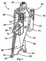
Figure 2 is a second perspective view from a downstream direction of an embodiment of the inlet baffle assembly ofFigure 1 ; -
Figure 3 is an exploded perspective view of an embodiment of the inlet baffle assembly ofFigure 1 ; -
Figure 4 is a perspective view of an embodiment of a fixed section of the inlet baffle assembly; -
Figure 5 is a first perspective view of an embodiment of a moveable section of the inlet baffle assembly; -
Figure 6 is a second perspective view of the embodiment of the moveable section of the inlet baffle assembly ofFig. 5 ; -
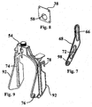
Figure 7 is a side perspective view of an embodiment of a link arm of the inlet baffle assembly; -
Figure 8 is a side perspective view of an embodiment of a flow control component of the inlet baffle assembly; -
Figure 9 is a side perspective view of an embodiment of an actuator component of the inlet baffle assembly; -
Figure 10 is a first perspective view of an inlet baffle assembly in an open position viewed from downstream; -
Figure 11 is a second perspective view of the inlet baffle assembly ofFig. 10 in an open position, viewed from upstream; -
Figure 12 is a side perspective view of an embodiment of the inlet baffle assembly in a closed position; -
Figure 13 is a side perspective view of an embodiment of the inlet baffle assembly in an open position; -
Figure 14 is a top perspective view of an embodiment of the inlet baffle assembly in a closed position; -
Figure 15 is a top perspective view of an embodiment of the inlet baffle assembly in an open position; -
Figure 16 is a cross-sectional side perspective view of an embodiment of the inlet baffle assembly in a closed position; -
Figure 17 is a cross-sectional side perspective view of an embodiment of the inlet baffle assembly in an open position; and -
Figure 18 is a cross-sectional side plan view of an in-line interceptor. - An embodiment of an
inlet baffle assembly 20 is shown inFig. 1-17 . Theinlet baffle assembly 20 is designed to be used in an in-line interceptor 22 such as is depicted generally inFig. 18 . Referring toFig. 18 , an in-line interceptor orgrease interceptor 22 is used to separate fats, oil and grease from wastewater which originates from food preparation kitchens or other facilities. Theinterceptor 22 has aninflow opening 25 through which influent will pass during operation of theinterceptor 22. Theinterceptor 22 also includesoutflow opening 26 and agrease collecting chamber 28 hydraulically located between saidinflow opening 25 and saidoutflow opening 26. A bulkhead fitting 24 is shown connected to theinflow opening 25. - Referring to
Fig. 1 , theinlet baffle assembly 20 includes aninlet baffle 30 sized and shaped to fit into the grease collecting chamber 28 (Fig. 18 ). Theinlet baffle 30 defines a flow channel to direct the flow of influent into the collecting chamber. The inlet baffle is affixed within the chamber to permit it to do this, for example by being removably affixed to the bulkhead fitting. It will be understood that other means of affixing the inlet baffle in place are also comprehended. - In the embodiment shown in
Fig. 1 , the flow channel provides a fluid passageway between abaffle opening 32 and anopen bottom 50 of theinlet baffle 30. When theinlet baffle 30 is connected to the inflow opening 25 (Fig. 18 ) of the interceptor 22 (Fig. 18 ), the flow channel allows influent to pass through theinlet opening 25 and ultimately enter thegrease collecting chamber 28. The influent enters theinlet baffle 30 through theinflow opening 25 into thebaffle opening 32, through the flow channel and exits the open bottom 50 into the grease collecting chamber. Influent passing through theinflow opening 25 may include wastewater containing FOG and other debris. - The
inlet baffle 30 has a nominally fixedsection 34 and amoveable section 36. Although the fixedsection 34 is described as being 'fixed', it need not be permanently connected to inflow opening 25 (Fig. 18 ), so long as themoveable section 36 and fixedsection 34 are moveable relative to one another. For example, the nominally fixedsection 34 may be detachably connected, as described above, to the inflow opening 25 (Fig. 18 ). Preferably, themoveable section 36 is an elongate moving baffle half and the fixedsection 34 is an elongate moving baffle half. However, themoveable section 36 and the fixedsection 34 may take various forms and relative portions other than two halves, so long as themoveable section 36 is able to move in such a way that the interior of the inlet baffle is accessible for cleaning and inspection as described below. The relative movement of themoveable section 36 and the fixedsection 34 allows themoveable section 36 to move between a closed position as shown inFigs. 12 ,14 and16 and an open position as shown inFigs. 13 ,15 and17 . When themoveable section 36 is moved into the closed position relative to the fixedsection 34, the flow channel is established which allows influent to flow, most preferably, in a controlled manner into the grease collecting chamber. As shown, for example, inFigs. 12 and13 , themoveable section 36 may be operationally moved in its relative orientation away from the fixedsection 34 and into the open position. The fixedsection 34 may be affixed, such as by being clamped, retained in a retaining slot or groove, or attached with fasteners or the like, to the bulkhead fitting 24 of the in-line interceptor 22. The fixed section may provide an attachment point for themoveable section 36. - Preferably, fixed
section 34 and themoveable section 36 are sized and shaped to ultimately produce laminar flow of influent through the grease collecting chamber when themoveable section 36 is in a closed position. A laminar flow is preferred to optimize the separation of solids, FOG and wastewater as the fluid passes through the chamber from the inlet side to the outlet side. The flow through theinlet baffle 30 may be partially controlled by the shapes of each of the fixedsection 34 and themoveable section 36. As shown inFig. 2 , themoveable section 36 includes a generally cylindricalupper section 84 andflat sections 88 at the base. Theupper section 84 has a roundedtop 82. The fixedsection 34 has a unitaryflat section 86 as shown inFig. 3 . Theassembly 34 when in the closed position seeks to do the following: initially turbulently mix the influent so as to entrain air via the opening 40 (Fig. 6 ) this air being drawn in through theopening 40 under negative pressure created by flow as it accelerates through the flow control orifice 58 (Fig. 8 ) and into turbulence. On passing through the flow control orifice, influent continues downward through the inlet baffle assembly being initially influenced by the more cylindrical form of theupper portion 84 and then transitioning to the more linear form enclosed by theflat areas 88 and 86 (Fig. 3 ). During this transition the flow area increases to slow the flow speed and the smooth baffle shape and reduced flow speed help re-establish laminar flow. Other shapes are comprehended for the baffles provided that laminar flow is re-established after the turbulent air mixing and entraining section above. - Referring to
Figs. 8 and17 , theinlet baffle 30 includes aflow control element 38 associated with theinlet baffle 30 to control the rate of flow of influent entering the flow channel when themoveable section 36 is in the closed position. Preferably, theflow control element 38 further comprises aflow control orifice 58. Alternate shapes and designs forflow control element 38 may be used so long as the rate of fluid flow into the system can be adequately controlled. For example, the flow control element may take the form of a flow control plate. - Referring to
Fig. 17 , theflow control element 38 is positioned to be accessible for cleaning and inspection when themoveable section 36 is in the open position. Preferably, theflow control element 38 is fixed to themoveable section 36 of theinlet baffle 30 so that theflow control element 38 moves away from the fixedsection 34 of theinlet baffle 30 when themoveable section 36 is moved from the closed position to the open position, permitting access to the upstream side of theflow control element 38 and internal surfaces of theinlet baffle assembly 20 for cleaning. It will be understood that material which can block the opening in the flow control element will generally originate upstream. Thus, if, for example, an upstream sink has poor drainage, the sink user can simply go to the inline waste interceptor, open it, pull up the inlet baffle actuator as described herein, and get access to theflow control element 38, for prompt cleaning. - The
orifice 58 can be provided in a range of different sizes, where the specific size is appropriate for a specific design inlet flow and/or to comply with regulatory requirements. When themoveable section 36 is moved to an open position, obstructions within the upstream baffle retainer 100 (Fig. 17 ) and theinlet baffle 30, including at theflow control element 38, may be cleared passively, through the flow of released, backup wastewater, or actively, by physical cleaning by an operator. As shown inFigs. 1 and5 , theinlet baffle assembly 20 includes anintegrated air intake 40 to facilitate entrainment of air into the influent flow. Air entrainment is desirable to allow buoyant bubbles of air to adhere to droplets of oil, thereby causing them to rise or separate more quickly when in the chamber. Thus, the initial part of the flow through the inlet opening, through the flow control element and then down the baffle past theair intake 40 is most preferably somewhat turbulent to encourage mixing of air into the influent as described above. - In the embodiment of
Fig. 1 , theintegrated air intake 40 is illustrated by a single opening and is preferably located above the operational static water level of theinterceptor 28 positioned generally in the upper portion of themoveable section 36. Theintegrated air intake 40 may take a variety of different forms (such as one or more openings) and need not be located within themoveable section 36 provided that theair intake 40 allows air to enter the influent flow from outside theinlet baffle assembly 20 and most preferably in a way that lets the air combine with a turbulent influent. For example, theinlet interceptor 22 may be a closed compartment having a lid 90 (Fig. 18 ) and having an atmospherically balanced and vented environment from which air may be entrained into theair intake 40. In other words, air is mixed with the influent air, and then allowed to bubble up and resupply the air space above the fluid level in the chamber. Theintegrated air intake 40 is preferably located on an upper portion of theinlet baffle 30 to ensure that theair intake 40 generally lies above the fluid level in theinterceptor 22. Although in the embodiment shown, theair intake 40 is shown as a single linear detail, theair intake 40 may also include a different arrangement or number of holes which may have a variety of different shapes or sizes. Furthermore, theair intake 40 may also be placed on a different component of theinlet baffle 30, such as the fixedsection 34, or on both the fixedsection 34 and themoveable section 36, so long as theair intake 40 provides a mechanism for introducing air into the influent liquid in a turbulent portion of flow to assist in the formation of bubbles to aid hydromechanical separation of the FOG from the influent. - As shown in
Fig. 10 , the hinge pins 60 and 62 (Fig. 2 ) are integrated to fixedsection 34. Thepins details 44 onmoveable section 36. The hinge details 44 define arotational axis 52 which is adjacent theopen bottom 50. Anactuator assembly 46 is connected between the fixedsection 34 and themoveable section 36 of theinlet baffle 30. When actuated, theactuator assembly 46 moves themoveable section 36 between the open position and the closed position. Preferably, theactuator assembly 46 is manually operable and is comprised oflink arms 48 and anactuator component 54 which are operatively connected between the fixedsection 34 andmoveable section 36 of theinlet baffle assembly 30. Theactuator component 54 may be in the form of a pull handle. Thelink arms 48 includeslots 66 which interface withpins 68 on themoveable section 36 andslots 72 which interface topins 64 on the fixedsection 34. The fixedsection 34 includes extension features 80 (Fig. 4 ) which each extend perpendicularly from the unitaryflat section 86 of the fixedsection 34. Eachextension feature 80 includes one of each pair of pivot points 64 and 70. - As shown in
Fig. 9 , thehandle 54 includes a connectingelement 92 on each side of thehandle 54. Each connectingelement 92 has anelongate slot 74 which interfaces withpivots section 34. As shown inFig. 10 , at the base of each connectingelement 92 is apivot 76 which interfaces to acorresponding pivot hole 98 in each of thelink arms 48. Thelink arms 48 allow themoveable section 36 to rotate aboutaxis 52 and tilt away from the fixedsection 34 to an open position, opening theinlet baffle 30 and exposing the upstream face of theflow control element 38 and allowing obstructions to be cleared as previously described. - As shown in
Fig. 2 , the hingedattachment 44 includes a pair of hinge pins 60, 62, on opposite sides of each of the fixedsection 34 and themoveable section 36 , which also allow themoveable section 34 to pivot away from the inflow opening 100 (Fig. 17 ). As shown, the hinged attachment is placed at the bottom of the baffle assembly. This permits the top to open when the baffles are hinged apart. While this is the most preferred form of the present invention, other hinged positions and configurations are also comprehended. All that is required is an actuator component which is clear of the influent and retained fluids, and which can open the moveable baffle to permit the visual inspection and then cleaning of the flow control element as needed. - As shown in
Fig. 3 , theactuator component 54 provides a mechanism for manoeuvering thelink arms 48 and causes the inlet baffle to move between the open position and the closed position as theactuator component 54 is raised and lowered, respectively. Theactuator component 54 includes catch hooks 78 which interface withpins 68 to lock themoveable section 36 into the closed position to allow the assembly to stay closed against the force of any inlet fluid flow. Thepins 68 also provide extension limits within slots 66 (Fig. 3 ) to control the maximum degree of openness. Although pivoting displacement provides good results, other forms of displacement are also comprehended. For example, the moveable section could be translated straight up on guides, or straight out. As well the moveable section could be completely detachable rather than being pivotally attached. All that is required is that the upstream side of the flow control element is exposed for ease of cleaning. - In operation, the interior of the
inlet baffle assembly 20 can be cleaned by moving themoveable section 36 into the open position as shown inFigs. 13 ,15 and17 and by cleaning theinlet baffle assembly 20 while themoveable section 36 is in the open position. After being cleaned, themoveable section 36 is moved back into the closed position as shown inFigs. 12 ,14 and16 in order to facilitate fluid flowing through theinlet baffle assembly 20 into thegrease collecting chamber 28. Theactuator 54 is moved in a vertical plane to move themoveable section 36 between the open position and the closed position. Theactuator assembly 46 may be actuated by manually operating thehandle 54. Theflow control element 38 moves away from the baffle retainer component 100 (Fig. 17 ) when themoveable section 36 is moved into the open position, allowing backed-up wastewater and debris to flow into thegrease collection chamber 28 which may be cleared using a pump for removal, for example. - The operation of the
actuator assembly 46 can be understood with reference toFigs. 12 and13 . To open the inlet baffle, an operator pulls theactuator component 54 either by hand or with an implement so that the catch hooks 78 are lifted from thepins 68. When lifted, theactuator component 54 moves upwards vertically. The motion of thehandle 54 upwards causes thepivot 76 andpivot hole 98 to move upwards which in turn results in the upper end of thelink arms 48 moving away from the fixedsection 34. Themoveable section 36 thereby moves apart at the top from the fixedsection 34. The interaction between theelongate slots 74 and thepins section 34 restrict the relative motion of theactuator component 54 in a vertical direction. Thepins slots link arms 48 as theactuator component 54 is lifted. As shown inFig. 17 , in the open position, themoveable section 36 exposes the upstream face of theflow control element 38 from its position pressed against the inletbaffle retainer component 100. Once cleaned, the inlet baffle may be closed by the operator pushing down on theactuator component 54, either by hand or using an implement which draws themoveable section 36 and fixedsection 34 together until the catch hooks 78 are locked into place on thepins 68. The mechanism will stop when fully closed. An implement may be desirable to actuate theactuator assembly 46 when theinlet baffle assembly 20 is installed at greater than arm's length from the point of access of the operator. Detail 101 (Fig. 16 ) provides an attachment feature integrated withpull handle 54. - The
inlet baffle assembly 20 may be constructed from a broad range of materials including but not limited to moulded or formed plastic. - In the claims, the word "comprising" is used in its inclusive sense and does not exclude other elements being present. The indefinite article "a" before a claim feature does not exclude more than one of the feature being present.
Claims (15)
- An inlet baffle assembly (20) for an in-line interceptor (22) used to separate fats, oil and grease from wastewater, the interceptor (22) having a wastewater inflow opening (25), an outflow opening (26) and a grease collecting chamber (28) hydraulically located between said inflow opening (25) and said outflow opening (26), the inlet baffle assembly (20) comprising:an inlet baffle (30) sized and shaped to fit within the grease collecting chamber (28) of the interceptor (22), and adapted to operatively connect to said wastewater inflow opening (25) of said interceptor (22), said inlet baffle (30) defining a flow channel therethrough for directing wastewater entering from the wastewater inflow opening (25) into the grease collecting chamber (28);said inlet baffle (30) comprising a first section (34), and a second section (36) moveable from said first section (34) between an open position and a closed position anda flow control element (38) positioned in said inlet baffle (30) at an upstream end of said flow channel;wherein said flow control element (38) is adapted to control a rate or flow characteristic of said wastewater entering said flow channel when said second section (36) of said inlet baffle (30) is in said closed position; andwherein, said flow control element (38) is accessible for cleaning and inspection when said second section (36) of the said inlet baffle (30) is in said open position.
- The inlet baffle assembly (20) of claim 1 further comprising an integrated air intake (40) to facilitate entrainment of air into said wastewater flow.
- The inlet baffle assembly (20) of claim 1, wherein the first section (34) is connected to the inflow opening (25) and the second section (36) is associated with the first section (34), in such a manner as to allow the second section (36) to be moved away from the first section (34).
- The inlet baffle assembly (20) of claim 3, further comprising a hinge (44) operationally related to said second section (36) and said first section (34).
- The inlet baffle assembly (20) of claim 3, wherein the inlet baffle (30) further comprises an open bottom (50), optionally further comprising a hinge (44) integrated attachment connected to said second section (36) and said first section (34), the hinge (44) being pivoted around a rotational axis and wherein the rotational axis of the hinged attachment is adjacent the open bottom (50).
- The inlet baffle assembly (20) of claim 3, further comprising an actuator (46) connected between the first section (34) and the second section (36) of the inlet baffle (30), wherein the actuator (46) moves the second section (36) between the open position and the closed position, optionally wherein the actuator (46) is manually operable and is comprised of link arms (48) and an actuator component (54) which are operatively connected between the first and second sections (34, 36) of the inlet baffle (30).
- The inlet baffle assembly (20) of claim 3, wherein the flow control Element (38) further comprises a flow control plate including an orifice (58), or wherein the flow control element (38) further comprises a flow control plate fixed to the second section (36) of the inlet baffle (30) so that the flow control plate moves away from the first section (34) of the inlet baffle (30) when the second section (36) is moved from the closed position to the open position to permit access to an inflow opening (25), the flow control element (38) and internal surfaces of the inlet baffle assembly (30) for cleaning.
- The inlet baffle assembly (20) of claim 3, in which the first section (34) of the inlet baffle (30) further comprises an elongate fixed baffle half and the second section (36) of the inlet baffle (30) further comprises an elongate moving baffle half and said flow channel is formed between them, optionally further comprising the elongate fixed baffle half and the elongate moveable baffle half being sized and shaped to produce a laminar flow of wastewater with reduced velocity into the grease collecting chamber (28).
- The inlet baffle assembly (20) of any one of claim 1 to 7, further comprising the inlet baffle (30) and the flow control element being formed from a plastic material.
- The inlet baffle assembly (20) of claim 6, further including a removable handle extension to facilitate manual actuation of said handle (54) in a below grade in-line interceptor.
- The inlet baffle assembly (20) of claim 1, further including guide tabs which locate said assembly (30) within said in-line interceptor (28), optionally wherein said guide tabs are sized and shaped to be received in vertical guide slots on said in-line interceptor (22).
- The inlet baffle assembly (20) of claim 1, wherein said flow control Element (38) includes both a flow restricting orifice (58) and a flow deflector to direct flow within said baffle (30).
- A method of cleaning an inlet baffle assembly (20) in an in-line interceptor (22), said in-line interceptor (22) having a wastewater inflow opening (25), an outflow opening (25) and a grease collecting chamber (28) hydraulically located between said inflow opening (25) and said outflow opening (26), said method comprising:providing an inlet baffle assembly (20) within the in-line interceptor (22), the inlet baffle assembly (20) comprising:an inlet baffle (30) defining a flow channel therethrough for directing wastewater flowing from the wastewater inflow opening (25) into the grease collecting chamber (28);said inlet baffle (30) comprising a first section (34), and a second section (36) moveable from said first section (34) between an open position allowing access to said flow channel, and a closed position preventing access to said flow channel; anda flow control element (38) positioned in said inlet baffle (30) at an upstream end of said flow channel, wherein said flow control element (38) is adapted to control a rate or flow characteristic of the wastewater entering said flow channel when said second section (36) is in said closed position;operatively connecting said flow channel of said inlet baffle assembly (30) to the wastewater inflow opening (25) of the in-line interceptor (22);moving said second section (36) of said inlet baffle (30) from said first section (34) to said open position to provide access to said flow control element (38) and said flow channel for cleaning;cleaning said flow control element (38) or said flow channel while said second section (36) of said inlet baffle (30) is in said open position; andmoving said second section (36) of said inlet baffle (30) to said closed position to facilitate said wastewater flowing through said flow control element (38) and said flow channel into the grease collecting chamber (28), thereby preventing access to said flow control element (38) and said flow channel.
- The method of claim 13, wherein the first section (34) of the baffle (30) is connected to the inflow opening (25), wherein the second section (36) is moveably connected to the first section (34) and wherein the inlet baffle assembly (20) further comprises an actuator (46) connected between the first section (34) and the second section (36) of the inlet baffle (30), and the method further comprising actuating the actuator (46) to move the second section (36) between the open position and the closed position, optionally in which the actuator (46) is further comprised of link arms (48) and a handle (54) and the method further comprising manually operating the handle (54) to move the second section (36) between the open position and the closed position, or in which the flow control element (38) further comprises a flow control plate and the method further comprising moving the flow control plate away from the first section (34) of the inlet baffle assembly (20) when the second section (36) is moved into the open position.
- The method of claim 13, in which cleaning the inlet baffle assembly (20) while the second section (36) is in the open position further comprises allowing backed-up wastewater and debris to flow into the grease collection chamber (28) when the second section (36) is in the open position.
Applications Claiming Priority (1)
| Application Number | Priority Date | Filing Date | Title |
|---|---|---|---|
| CA2835578A CA2835578C (en) | 2013-11-29 | 2013-11-29 | Inlet baffle assembly for an in-line interceptor |
Publications (2)
| Publication Number | Publication Date |
|---|---|
| EP2878350A1 EP2878350A1 (en) | 2015-06-03 |
| EP2878350B1 true EP2878350B1 (en) | 2016-08-24 |
Family
ID=52020941
Family Applications (1)
| Application Number | Title | Priority Date | Filing Date |
|---|---|---|---|
| EP14194010.6A Not-in-force EP2878350B1 (en) | 2013-11-29 | 2014-11-20 | Inlet baffle assembly for an in-line interceptor |
Country Status (9)
| Country | Link |
|---|---|
| US (1) | US9828759B2 (en) |
| EP (1) | EP2878350B1 (en) |
| AU (1) | AU2014265138A1 (en) |
| BR (1) | BR102014030048A2 (en) |
| CA (2) | CA2923639A1 (en) |
| ES (1) | ES2588398T3 (en) |
| MX (1) | MX2014014666A (en) |
| RU (1) | RU2014147384A (en) |
| ZA (1) | ZA201408485B (en) |
Families Citing this family (2)
| Publication number | Priority date | Publication date | Assignee | Title |
|---|---|---|---|---|
| US11578480B2 (en) * | 2017-01-30 | 2023-02-14 | Oldcastle Precast Inc. | Grease interceptor and method of use thereof |
| CA3085262C (en) | 2020-07-02 | 2025-04-01 | Canplas Industries Ltd. | An auxiliary baffle for a grease interceptor and a grease interceptor incorporating the same |
Family Cites Families (19)
| Publication number | Priority date | Publication date | Assignee | Title |
|---|---|---|---|---|
| US2003140A (en) | 1933-04-22 | 1935-05-28 | George J Dehn | Grease trap |
| US2285893A (en) * | 1940-12-27 | 1942-06-09 | Edward W N Boosey | Intake manifold for oil interceptors |
| US2414949A (en) | 1942-11-17 | 1947-01-28 | Hirshstein Joseph | Interceptor with flow control |
| DE1253674B (en) * | 1962-05-18 | 1967-11-09 | Jan Cornelissen Dipl Ing | Clarifying device for separating insoluble impurities from a liquid |
| US5030357A (en) * | 1990-09-11 | 1991-07-09 | Lowe Engineering Company | Oil/grease recovery method and apparatus |
| US5271853A (en) | 1992-09-22 | 1993-12-21 | Thermaco, Inc. | Inexpensive flow controller |
| US5505860A (en) | 1994-10-24 | 1996-04-09 | Sager; Robert J. | Grease and oil trap |
| US5714069A (en) | 1996-09-25 | 1998-02-03 | Sager; Robert | Apparatus for removing grease from waste water |
| CA2299134C (en) | 2000-02-23 | 2009-09-01 | Canplas Industries Ltd. | Wastewater separator and method of using same |
| AU2001237163A1 (en) | 2000-02-23 | 2001-09-03 | Canplas Industries Ltd. | Wastewater separator and method of using same |
| US6951615B2 (en) | 2003-03-25 | 2005-10-04 | Zurn Industries, Inc. | Grease removal system |
| US7296694B2 (en) | 2004-10-12 | 2007-11-20 | Weymouth Bret M | Tower-type grease removal apparatus for commercial grease trap assemblies |
| US7686961B1 (en) * | 2005-04-12 | 2010-03-30 | Glynne Michael J | Apparatus for removing dissolved and suspended contaminants from waste water |
| US8017004B2 (en) * | 2005-05-26 | 2011-09-13 | Trash Guard, Inc. | Storm drain and filter system |
| US7427356B2 (en) | 2005-09-01 | 2008-09-23 | Peter Chapin | Fats, oil and grease interceptor |
| US7452472B2 (en) | 2006-06-12 | 2008-11-18 | Josam Company | Grease interceptor having a grease removal device |
| US7481321B2 (en) | 2007-03-30 | 2009-01-27 | Schier Products Company | Interceptor for separating a mixture |
| CA2740678C (en) * | 2010-05-20 | 2013-10-22 | Best Management Products, Inc. | Water resistant hatch and hood |
| CA2769800C (en) | 2012-02-28 | 2018-08-14 | Canplas Industries Ltd. | Diffuser baffle for grease interceptor |
-
2013
- 2013-11-29 CA CA2923639A patent/CA2923639A1/en not_active Abandoned
- 2013-11-29 CA CA2835578A patent/CA2835578C/en active Active
-
2014
- 2014-07-08 US US14/325,718 patent/US9828759B2/en active Active
- 2014-11-19 ZA ZA2014/08485A patent/ZA201408485B/en unknown
- 2014-11-20 ES ES14194010.6T patent/ES2588398T3/en active Active
- 2014-11-20 EP EP14194010.6A patent/EP2878350B1/en not_active Not-in-force
- 2014-11-24 AU AU2014265138A patent/AU2014265138A1/en not_active Abandoned
- 2014-11-26 RU RU2014147384A patent/RU2014147384A/en not_active Application Discontinuation
- 2014-12-01 MX MX2014014666A patent/MX2014014666A/en active IP Right Grant
- 2014-12-01 BR BR102014030048A patent/BR102014030048A2/en not_active Application Discontinuation
Non-Patent Citations (1)
| Title |
|---|
| None * |
Also Published As
| Publication number | Publication date |
|---|---|
| US9828759B2 (en) | 2017-11-28 |
| CA2835578A1 (en) | 2015-05-29 |
| CA2835578C (en) | 2016-04-05 |
| BR102014030048A2 (en) | 2016-08-02 |
| US20150152629A1 (en) | 2015-06-04 |
| ES2588398T3 (en) | 2016-11-02 |
| CA2923639A1 (en) | 2015-05-29 |
| AU2014265138A1 (en) | 2015-06-18 |
| MX2014014666A (en) | 2015-09-16 |
| ZA201408485B (en) | 2015-11-25 |
| EP2878350A1 (en) | 2015-06-03 |
| RU2014147384A (en) | 2016-06-10 |
Similar Documents
| Publication | Publication Date | Title |
|---|---|---|
| US11826305B2 (en) | Emergency wash system | |
| US7011752B2 (en) | Wastewater separator and method of using same | |
| US9850651B2 (en) | Diffuser baffle for grease interceptor | |
| US9375659B2 (en) | Solids containment device for use within or in association with hydromechanical grease interceptor | |
| US9828759B2 (en) | Inlet baffle assembly for an in-line interceptor | |
| US7186346B1 (en) | Low cost indoor grease trap | |
| EP1259676B1 (en) | Wastewater separator and method of using same | |
| EP3610081B1 (en) | An l-shaped plumbing drainage fitting | |
| KR101162029B1 (en) | Drainage assembly with filter removing hair | |
| NZ702128A (en) | Inlet baffle assembly for an in-line interceptor | |
| CA2592294A1 (en) | Grey water diversion | |
| KR20110006860A (en) | Sink drainage structure | |
| US11686077B2 (en) | Pipe unclogging device | |
| CA2866911C (en) | An outlet well cover for an in-line grease interceptor | |
| KR0123883B1 (en) | An apparatus for removing a float and a bubble in cohesion station | |
| CN209098206U (en) | A kind of water treatment system of food safety detection vehicle | |
| JP2006320450A (en) | On/off valve and bathtub water control system | |
| KR20210107341A (en) | Housing apparatus for filters for water purifiers and water purifiers comprising the same | |
| GB2635313A (en) | Waste trap | |
| HK1092252A1 (en) | Lavatory with a removable washing platform | |
| US20100193040A1 (en) | Siphoning Group for Food Waste Disposers | |
| HK1071680B (en) | Washing platform | |
| CA2588948A1 (en) | Grey water diversion and filtration device | |
| NZ248787A (en) | Plumber's plunger has scraper, handle and collars |
Legal Events
| Date | Code | Title | Description |
|---|---|---|---|
| PUAI | Public reference made under article 153(3) epc to a published international application that has entered the european phase |
Free format text: ORIGINAL CODE: 0009012 |
|
| 17P | Request for examination filed |
Effective date: 20141120 |
|
| AK | Designated contracting states |
Kind code of ref document: A1 Designated state(s): AL AT BE BG CH CY CZ DE DK EE ES FI FR GB GR HR HU IE IS IT LI LT LU LV MC MK MT NL NO PL PT RO RS SE SI SK SM TR |
|
| AX | Request for extension of the european patent |
Extension state: BA ME |
|
| R17P | Request for examination filed (corrected) |
Effective date: 20150624 |
|
| RBV | Designated contracting states (corrected) |
Designated state(s): AL AT BE BG CH CY CZ DE DK EE ES FI FR GB GR HR HU IE IS IT LI LT LU LV MC MK MT NL NO PL PT RO RS SE SI SK SM TR |
|
| 17Q | First examination report despatched |
Effective date: 20151106 |
|
| GRAP | Despatch of communication of intention to grant a patent |
Free format text: ORIGINAL CODE: EPIDOSNIGR1 |
|
| INTG | Intention to grant announced |
Effective date: 20160511 |
|
| GRAS | Grant fee paid |
Free format text: ORIGINAL CODE: EPIDOSNIGR3 |
|
| GRAJ | Information related to disapproval of communication of intention to grant by the applicant or resumption of examination proceedings by the epo deleted |
Free format text: ORIGINAL CODE: EPIDOSDIGR1 |
|
| GRAL | Information related to payment of fee for publishing/printing deleted |
Free format text: ORIGINAL CODE: EPIDOSDIGR3 |
|
| GRAR | Information related to intention to grant a patent recorded |
Free format text: ORIGINAL CODE: EPIDOSNIGR71 |
|
| GRAA | (expected) grant |
Free format text: ORIGINAL CODE: 0009210 |
|
| INTG | Intention to grant announced |
Effective date: 20160707 |
|
| AK | Designated contracting states |
Kind code of ref document: B1 Designated state(s): AL AT BE BG CH CY CZ DE DK EE ES FI FR GB GR HR HU IE IS IT LI LT LU LV MC MK MT NL NO PL PT RO RS SE SI SK SM TR |
|
| REG | Reference to a national code |
Ref country code: GB Ref legal event code: FG4D |
|
| REG | Reference to a national code |
Ref country code: CH Ref legal event code: EP |
|
| REG | Reference to a national code |
Ref country code: AT Ref legal event code: REF Ref document number: 822558 Country of ref document: AT Kind code of ref document: T Effective date: 20160915 |
|
| REG | Reference to a national code |
Ref country code: IE Ref legal event code: FG4D |
|
| REG | Reference to a national code |
Ref country code: DE Ref legal event code: R096 Ref document number: 602014003255 Country of ref document: DE |
|
| REG | Reference to a national code |
Ref country code: FR Ref legal event code: PLFP Year of fee payment: 3 |
|
| REG | Reference to a national code |
Ref country code: ES Ref legal event code: FG2A Ref document number: 2588398 Country of ref document: ES Kind code of ref document: T3 Effective date: 20161102 |
|
| REG | Reference to a national code |
Ref country code: LT Ref legal event code: MG4D |
|
| REG | Reference to a national code |
Ref country code: NL Ref legal event code: MP Effective date: 20160824 |
|
| REG | Reference to a national code |
Ref country code: AT Ref legal event code: MK05 Ref document number: 822558 Country of ref document: AT Kind code of ref document: T Effective date: 20160824 |
|
| PG25 | Lapsed in a contracting state [announced via postgrant information from national office to epo] |
Ref country code: NO Free format text: LAPSE BECAUSE OF FAILURE TO SUBMIT A TRANSLATION OF THE DESCRIPTION OR TO PAY THE FEE WITHIN THE PRESCRIBED TIME-LIMIT Effective date: 20161124 Ref country code: LT Free format text: LAPSE BECAUSE OF FAILURE TO SUBMIT A TRANSLATION OF THE DESCRIPTION OR TO PAY THE FEE WITHIN THE PRESCRIBED TIME-LIMIT Effective date: 20160824 Ref country code: HR Free format text: LAPSE BECAUSE OF FAILURE TO SUBMIT A TRANSLATION OF THE DESCRIPTION OR TO PAY THE FEE WITHIN THE PRESCRIBED TIME-LIMIT Effective date: 20160824 Ref country code: RS Free format text: LAPSE BECAUSE OF FAILURE TO SUBMIT A TRANSLATION OF THE DESCRIPTION OR TO PAY THE FEE WITHIN THE PRESCRIBED TIME-LIMIT Effective date: 20160824 Ref country code: FI Free format text: LAPSE BECAUSE OF FAILURE TO SUBMIT A TRANSLATION OF THE DESCRIPTION OR TO PAY THE FEE WITHIN THE PRESCRIBED TIME-LIMIT Effective date: 20160824 Ref country code: NL Free format text: LAPSE BECAUSE OF FAILURE TO SUBMIT A TRANSLATION OF THE DESCRIPTION OR TO PAY THE FEE WITHIN THE PRESCRIBED TIME-LIMIT Effective date: 20160824 |
|
| PG25 | Lapsed in a contracting state [announced via postgrant information from national office to epo] |
Ref country code: GR Free format text: LAPSE BECAUSE OF FAILURE TO SUBMIT A TRANSLATION OF THE DESCRIPTION OR TO PAY THE FEE WITHIN THE PRESCRIBED TIME-LIMIT Effective date: 20161125 Ref country code: AT Free format text: LAPSE BECAUSE OF FAILURE TO SUBMIT A TRANSLATION OF THE DESCRIPTION OR TO PAY THE FEE WITHIN THE PRESCRIBED TIME-LIMIT Effective date: 20160824 Ref country code: PT Free format text: LAPSE BECAUSE OF FAILURE TO SUBMIT A TRANSLATION OF THE DESCRIPTION OR TO PAY THE FEE WITHIN THE PRESCRIBED TIME-LIMIT Effective date: 20161226 Ref country code: BE Free format text: LAPSE BECAUSE OF NON-PAYMENT OF DUE FEES Effective date: 20161130 Ref country code: LV Free format text: LAPSE BECAUSE OF FAILURE TO SUBMIT A TRANSLATION OF THE DESCRIPTION OR TO PAY THE FEE WITHIN THE PRESCRIBED TIME-LIMIT Effective date: 20160824 Ref country code: SE Free format text: LAPSE BECAUSE OF FAILURE TO SUBMIT A TRANSLATION OF THE DESCRIPTION OR TO PAY THE FEE WITHIN THE PRESCRIBED TIME-LIMIT Effective date: 20160824 |
|
| PG25 | Lapsed in a contracting state [announced via postgrant information from national office to epo] |
Ref country code: EE Free format text: LAPSE BECAUSE OF FAILURE TO SUBMIT A TRANSLATION OF THE DESCRIPTION OR TO PAY THE FEE WITHIN THE PRESCRIBED TIME-LIMIT Effective date: 20160824 Ref country code: RO Free format text: LAPSE BECAUSE OF FAILURE TO SUBMIT A TRANSLATION OF THE DESCRIPTION OR TO PAY THE FEE WITHIN THE PRESCRIBED TIME-LIMIT Effective date: 20160824 |
|
| REG | Reference to a national code |
Ref country code: DE Ref legal event code: R097 Ref document number: 602014003255 Country of ref document: DE |
|
| PG25 | Lapsed in a contracting state [announced via postgrant information from national office to epo] |
Ref country code: BE Free format text: LAPSE BECAUSE OF FAILURE TO SUBMIT A TRANSLATION OF THE DESCRIPTION OR TO PAY THE FEE WITHIN THE PRESCRIBED TIME-LIMIT Effective date: 20160824 Ref country code: PL Free format text: LAPSE BECAUSE OF FAILURE TO SUBMIT A TRANSLATION OF THE DESCRIPTION OR TO PAY THE FEE WITHIN THE PRESCRIBED TIME-LIMIT Effective date: 20160824 Ref country code: CZ Free format text: LAPSE BECAUSE OF FAILURE TO SUBMIT A TRANSLATION OF THE DESCRIPTION OR TO PAY THE FEE WITHIN THE PRESCRIBED TIME-LIMIT Effective date: 20160824 Ref country code: BG Free format text: LAPSE BECAUSE OF FAILURE TO SUBMIT A TRANSLATION OF THE DESCRIPTION OR TO PAY THE FEE WITHIN THE PRESCRIBED TIME-LIMIT Effective date: 20161124 Ref country code: SM Free format text: LAPSE BECAUSE OF FAILURE TO SUBMIT A TRANSLATION OF THE DESCRIPTION OR TO PAY THE FEE WITHIN THE PRESCRIBED TIME-LIMIT Effective date: 20160824 Ref country code: DK Free format text: LAPSE BECAUSE OF FAILURE TO SUBMIT A TRANSLATION OF THE DESCRIPTION OR TO PAY THE FEE WITHIN THE PRESCRIBED TIME-LIMIT Effective date: 20160824 Ref country code: SK Free format text: LAPSE BECAUSE OF FAILURE TO SUBMIT A TRANSLATION OF THE DESCRIPTION OR TO PAY THE FEE WITHIN THE PRESCRIBED TIME-LIMIT Effective date: 20160824 |
|
| PLBE | No opposition filed within time limit |
Free format text: ORIGINAL CODE: 0009261 |
|
| STAA | Information on the status of an ep patent application or granted ep patent |
Free format text: STATUS: NO OPPOSITION FILED WITHIN TIME LIMIT |
|
| 26N | No opposition filed |
Effective date: 20170526 |
|
| PG25 | Lapsed in a contracting state [announced via postgrant information from national office to epo] |
Ref country code: SI Free format text: LAPSE BECAUSE OF FAILURE TO SUBMIT A TRANSLATION OF THE DESCRIPTION OR TO PAY THE FEE WITHIN THE PRESCRIBED TIME-LIMIT Effective date: 20160824 |
|
| PG25 | Lapsed in a contracting state [announced via postgrant information from national office to epo] |
Ref country code: LU Free format text: LAPSE BECAUSE OF NON-PAYMENT OF DUE FEES Effective date: 20161130 |
|
| REG | Reference to a national code |
Ref country code: FR Ref legal event code: PLFP Year of fee payment: 4 |
|
| PG25 | Lapsed in a contracting state [announced via postgrant information from national office to epo] |
Ref country code: HU Free format text: LAPSE BECAUSE OF FAILURE TO SUBMIT A TRANSLATION OF THE DESCRIPTION OR TO PAY THE FEE WITHIN THE PRESCRIBED TIME-LIMIT; INVALID AB INITIO Effective date: 20141120 |
|
| PG25 | Lapsed in a contracting state [announced via postgrant information from national office to epo] |
Ref country code: MK Free format text: LAPSE BECAUSE OF FAILURE TO SUBMIT A TRANSLATION OF THE DESCRIPTION OR TO PAY THE FEE WITHIN THE PRESCRIBED TIME-LIMIT Effective date: 20160824 Ref country code: IS Free format text: LAPSE BECAUSE OF FAILURE TO SUBMIT A TRANSLATION OF THE DESCRIPTION OR TO PAY THE FEE WITHIN THE PRESCRIBED TIME-LIMIT Effective date: 20160824 Ref country code: CY Free format text: LAPSE BECAUSE OF FAILURE TO SUBMIT A TRANSLATION OF THE DESCRIPTION OR TO PAY THE FEE WITHIN THE PRESCRIBED TIME-LIMIT Effective date: 20160824 Ref country code: MC Free format text: LAPSE BECAUSE OF FAILURE TO SUBMIT A TRANSLATION OF THE DESCRIPTION OR TO PAY THE FEE WITHIN THE PRESCRIBED TIME-LIMIT Effective date: 20160824 |
|
| PG25 | Lapsed in a contracting state [announced via postgrant information from national office to epo] |
Ref country code: CH Free format text: LAPSE BECAUSE OF NON-PAYMENT OF DUE FEES Effective date: 20171130 Ref country code: LI Free format text: LAPSE BECAUSE OF NON-PAYMENT OF DUE FEES Effective date: 20171130 |
|
| PG25 | Lapsed in a contracting state [announced via postgrant information from national office to epo] |
Ref country code: MT Free format text: LAPSE BECAUSE OF NON-PAYMENT OF DUE FEES Effective date: 20161120 |
|
| REG | Reference to a national code |
Ref country code: FR Ref legal event code: PLFP Year of fee payment: 5 |
|
| PG25 | Lapsed in a contracting state [announced via postgrant information from national office to epo] |
Ref country code: TR Free format text: LAPSE BECAUSE OF FAILURE TO SUBMIT A TRANSLATION OF THE DESCRIPTION OR TO PAY THE FEE WITHIN THE PRESCRIBED TIME-LIMIT Effective date: 20160824 Ref country code: AL Free format text: LAPSE BECAUSE OF FAILURE TO SUBMIT A TRANSLATION OF THE DESCRIPTION OR TO PAY THE FEE WITHIN THE PRESCRIBED TIME-LIMIT Effective date: 20160824 |
|
| PGFP | Annual fee paid to national office [announced via postgrant information from national office to epo] |
Ref country code: DE Payment date: 20181106 Year of fee payment: 5 Ref country code: IE Payment date: 20181109 Year of fee payment: 5 |
|
| PGFP | Annual fee paid to national office [announced via postgrant information from national office to epo] |
Ref country code: GB Payment date: 20181114 Year of fee payment: 5 Ref country code: ES Payment date: 20181203 Year of fee payment: 5 Ref country code: FR Payment date: 20181011 Year of fee payment: 5 Ref country code: IT Payment date: 20181122 Year of fee payment: 5 |
|
| REG | Reference to a national code |
Ref country code: DE Ref legal event code: R119 Ref document number: 602014003255 Country of ref document: DE |
|
| GBPC | Gb: european patent ceased through non-payment of renewal fee |
Effective date: 20191120 |
|
| PG25 | Lapsed in a contracting state [announced via postgrant information from national office to epo] |
Ref country code: GB Free format text: LAPSE BECAUSE OF NON-PAYMENT OF DUE FEES Effective date: 20191120 Ref country code: IE Free format text: LAPSE BECAUSE OF NON-PAYMENT OF DUE FEES Effective date: 20191120 Ref country code: IT Free format text: LAPSE BECAUSE OF NON-PAYMENT OF DUE FEES Effective date: 20191120 Ref country code: DE Free format text: LAPSE BECAUSE OF NON-PAYMENT OF DUE FEES Effective date: 20200603 Ref country code: FR Free format text: LAPSE BECAUSE OF NON-PAYMENT OF DUE FEES Effective date: 20191130 |
|
| REG | Reference to a national code |
Ref country code: ES Ref legal event code: FD2A Effective date: 20210526 |
|
| PG25 | Lapsed in a contracting state [announced via postgrant information from national office to epo] |
Ref country code: ES Free format text: LAPSE BECAUSE OF NON-PAYMENT OF DUE FEES Effective date: 20191121 |