EP2878324B1 - Safety syringe - Google Patents
Safety syringe Download PDFInfo
- Publication number
- EP2878324B1 EP2878324B1 EP14195373.7A EP14195373A EP2878324B1 EP 2878324 B1 EP2878324 B1 EP 2878324B1 EP 14195373 A EP14195373 A EP 14195373A EP 2878324 B1 EP2878324 B1 EP 2878324B1
- Authority
- EP
- European Patent Office
- Prior art keywords
- flange
- needle holder
- ring wall
- interlocking seat
- barrel
- Prior art date
- Legal status (The legal status is an assumption and is not a legal conclusion. Google has not performed a legal analysis and makes no representation as to the accuracy of the status listed.)
- Active
Links
- 208000012266 Needlestick injury Diseases 0.000 description 17
- 238000002347 injection Methods 0.000 description 10
- 239000007924 injection Substances 0.000 description 10
- 239000008280 blood Substances 0.000 description 2
- 210000004369 blood Anatomy 0.000 description 2
- 239000012530 fluid Substances 0.000 description 2
- 206010069803 Injury associated with device Diseases 0.000 description 1
- 208000027418 Wounds and injury Diseases 0.000 description 1
- 230000003139 buffering effect Effects 0.000 description 1
- 230000006378 damage Effects 0.000 description 1
- 239000003814 drug Substances 0.000 description 1
- 230000000694 effects Effects 0.000 description 1
- 208000015181 infectious disease Diseases 0.000 description 1
- 208000014674 injury Diseases 0.000 description 1
- 239000007788 liquid Substances 0.000 description 1
- 238000000034 method Methods 0.000 description 1
- 235000015097 nutrients Nutrition 0.000 description 1
- 239000000243 solution Substances 0.000 description 1
- 239000002699 waste material Substances 0.000 description 1
Images


Classifications
-
- A—HUMAN NECESSITIES
- A61—MEDICAL OR VETERINARY SCIENCE; HYGIENE
- A61M—DEVICES FOR INTRODUCING MEDIA INTO, OR ONTO, THE BODY; DEVICES FOR TRANSDUCING BODY MEDIA OR FOR TAKING MEDIA FROM THE BODY; DEVICES FOR PRODUCING OR ENDING SLEEP OR STUPOR
- A61M5/00—Devices for bringing media into the body in a subcutaneous, intra-vascular or intramuscular way; Accessories therefor, e.g. filling or cleaning devices, arm-rests
- A61M5/178—Syringes
- A61M5/31—Details
- A61M5/32—Needles; Details of needles pertaining to their connection with syringe or hub; Accessories for bringing the needle into, or holding the needle on, the body; Devices for protection of needles
- A61M5/3205—Apparatus for removing or disposing of used needles or syringes, e.g. containers; Means for protection against accidental injuries from used needles
- A61M5/321—Means for protection against accidental injuries by used needles
- A61M5/322—Retractable needles, i.e. disconnected from and withdrawn into the syringe barrel by the piston
- A61M5/3221—Constructional features thereof, e.g. to improve manipulation or functioning
-
- A—HUMAN NECESSITIES
- A61—MEDICAL OR VETERINARY SCIENCE; HYGIENE
- A61M—DEVICES FOR INTRODUCING MEDIA INTO, OR ONTO, THE BODY; DEVICES FOR TRANSDUCING BODY MEDIA OR FOR TAKING MEDIA FROM THE BODY; DEVICES FOR PRODUCING OR ENDING SLEEP OR STUPOR
- A61M5/00—Devices for bringing media into the body in a subcutaneous, intra-vascular or intramuscular way; Accessories therefor, e.g. filling or cleaning devices, arm-rests
- A61M5/178—Syringes
-
- A—HUMAN NECESSITIES
- A61—MEDICAL OR VETERINARY SCIENCE; HYGIENE
- A61B—DIAGNOSIS; SURGERY; IDENTIFICATION
- A61B17/00—Surgical instruments, devices or methods, e.g. tourniquets
-
- A—HUMAN NECESSITIES
- A61—MEDICAL OR VETERINARY SCIENCE; HYGIENE
- A61M—DEVICES FOR INTRODUCING MEDIA INTO, OR ONTO, THE BODY; DEVICES FOR TRANSDUCING BODY MEDIA OR FOR TAKING MEDIA FROM THE BODY; DEVICES FOR PRODUCING OR ENDING SLEEP OR STUPOR
- A61M5/00—Devices for bringing media into the body in a subcutaneous, intra-vascular or intramuscular way; Accessories therefor, e.g. filling or cleaning devices, arm-rests
- A61M5/178—Syringes
- A61M5/31—Details
- A61M5/32—Needles; Details of needles pertaining to their connection with syringe or hub; Accessories for bringing the needle into, or holding the needle on, the body; Devices for protection of needles
- A61M5/3205—Apparatus for removing or disposing of used needles or syringes, e.g. containers; Means for protection against accidental injuries from used needles
- A61M5/321—Means for protection against accidental injuries by used needles
- A61M5/322—Retractable needles, i.e. disconnected from and withdrawn into the syringe barrel by the piston
-
- A—HUMAN NECESSITIES
- A61—MEDICAL OR VETERINARY SCIENCE; HYGIENE
- A61M—DEVICES FOR INTRODUCING MEDIA INTO, OR ONTO, THE BODY; DEVICES FOR TRANSDUCING BODY MEDIA OR FOR TAKING MEDIA FROM THE BODY; DEVICES FOR PRODUCING OR ENDING SLEEP OR STUPOR
- A61M5/00—Devices for bringing media into the body in a subcutaneous, intra-vascular or intramuscular way; Accessories therefor, e.g. filling or cleaning devices, arm-rests
- A61M5/50—Devices for bringing media into the body in a subcutaneous, intra-vascular or intramuscular way; Accessories therefor, e.g. filling or cleaning devices, arm-rests having means for preventing re-use, or for indicating if defective, used, tampered with or unsterile
-
- A—HUMAN NECESSITIES
- A61—MEDICAL OR VETERINARY SCIENCE; HYGIENE
- A61M—DEVICES FOR INTRODUCING MEDIA INTO, OR ONTO, THE BODY; DEVICES FOR TRANSDUCING BODY MEDIA OR FOR TAKING MEDIA FROM THE BODY; DEVICES FOR PRODUCING OR ENDING SLEEP OR STUPOR
- A61M5/00—Devices for bringing media into the body in a subcutaneous, intra-vascular or intramuscular way; Accessories therefor, e.g. filling or cleaning devices, arm-rests
- A61M5/178—Syringes
- A61M5/31—Details
- A61M5/315—Pistons; Piston-rods; Guiding, blocking or restricting the movement of the rod or piston; Appliances on the rod for facilitating dosing ; Dosing mechanisms
- A61M5/31511—Piston or piston-rod constructions, e.g. connection of piston with piston-rod
- A61M2005/31516—Piston or piston-rod constructions, e.g. connection of piston with piston-rod reducing dead-space in the syringe barrel after delivery
-
- A—HUMAN NECESSITIES
- A61—MEDICAL OR VETERINARY SCIENCE; HYGIENE
- A61M—DEVICES FOR INTRODUCING MEDIA INTO, OR ONTO, THE BODY; DEVICES FOR TRANSDUCING BODY MEDIA OR FOR TAKING MEDIA FROM THE BODY; DEVICES FOR PRODUCING OR ENDING SLEEP OR STUPOR
- A61M5/00—Devices for bringing media into the body in a subcutaneous, intra-vascular or intramuscular way; Accessories therefor, e.g. filling or cleaning devices, arm-rests
- A61M5/178—Syringes
- A61M5/31—Details
- A61M5/32—Needles; Details of needles pertaining to their connection with syringe or hub; Accessories for bringing the needle into, or holding the needle on, the body; Devices for protection of needles
- A61M5/3205—Apparatus for removing or disposing of used needles or syringes, e.g. containers; Means for protection against accidental injuries from used needles
- A61M5/321—Means for protection against accidental injuries by used needles
- A61M5/322—Retractable needles, i.e. disconnected from and withdrawn into the syringe barrel by the piston
- A61M5/3221—Constructional features thereof, e.g. to improve manipulation or functioning
- A61M2005/323—Connection between plunger distal end and needle hub proximal end, e.g. stud protruding from the plunger
-
- A—HUMAN NECESSITIES
- A61—MEDICAL OR VETERINARY SCIENCE; HYGIENE
- A61M—DEVICES FOR INTRODUCING MEDIA INTO, OR ONTO, THE BODY; DEVICES FOR TRANSDUCING BODY MEDIA OR FOR TAKING MEDIA FROM THE BODY; DEVICES FOR PRODUCING OR ENDING SLEEP OR STUPOR
- A61M5/00—Devices for bringing media into the body in a subcutaneous, intra-vascular or intramuscular way; Accessories therefor, e.g. filling or cleaning devices, arm-rests
- A61M5/178—Syringes
- A61M5/31—Details
- A61M5/32—Needles; Details of needles pertaining to their connection with syringe or hub; Accessories for bringing the needle into, or holding the needle on, the body; Devices for protection of needles
- A61M5/3205—Apparatus for removing or disposing of used needles or syringes, e.g. containers; Means for protection against accidental injuries from used needles
- A61M5/321—Means for protection against accidental injuries by used needles
- A61M5/322—Retractable needles, i.e. disconnected from and withdrawn into the syringe barrel by the piston
- A61M5/3221—Constructional features thereof, e.g. to improve manipulation or functioning
- A61M2005/3231—Proximal end of needle captured or embedded inside piston head, e.g. by friction or hooks
-
- A—HUMAN NECESSITIES
- A61—MEDICAL OR VETERINARY SCIENCE; HYGIENE
- A61M—DEVICES FOR INTRODUCING MEDIA INTO, OR ONTO, THE BODY; DEVICES FOR TRANSDUCING BODY MEDIA OR FOR TAKING MEDIA FROM THE BODY; DEVICES FOR PRODUCING OR ENDING SLEEP OR STUPOR
- A61M5/00—Devices for bringing media into the body in a subcutaneous, intra-vascular or intramuscular way; Accessories therefor, e.g. filling or cleaning devices, arm-rests
- A61M5/178—Syringes
- A61M5/31—Details
- A61M5/32—Needles; Details of needles pertaining to their connection with syringe or hub; Accessories for bringing the needle into, or holding the needle on, the body; Devices for protection of needles
- A61M5/34—Constructions for connecting the needle, e.g. to syringe nozzle or needle hub
- A61M5/344—Constructions for connecting the needle, e.g. to syringe nozzle or needle hub using additional parts, e.g. clamping rings or collets
Definitions
- the present invention relates to medical equipment and more particularly, to a safety syringe.
- a syringe is an implement adapted for use with a needlestick to inject a liquid medicine, blood or other nutrient solution into the human body. After the injection, the needlestick has the human blood adhered thereto. Therefore, the needlestick should be disposed of safety after the use, avoiding medicare personnel or other persons from being injured by the needlestick accidentally.
- the most commonly applied method for disposal of a used needlestick is to insert the needlestick into a needlestick cap after its use.
- the medicare personnel inserts the needlestick into a needlestick cap, the hand of the medicare personnel can be injured by the needlestick accidentally due to their own carelessness or by other external forces, increasing the risk of infection.
- US 6,488,657 discloses a needle holder positioning structure for a safety syringe in accordance with the preamble of claim 1.
- retraction of the needle holder is complicated and requires much space and high retraction forces due to friction between needle holder and the structure's barrel, thus being inefficient and insecure.
- the present invention has been accomplished under the circumstances in view. It is the main object of the present invention to provide a safety syringe, which is easy to operate and can accurately receive the needlestick after its use, reducing the risk of accidental needlestick injuries.
- a safety syringe comprises a barrel, a needle holder, an interlocking seat, and a plunger according to claim 1.
- the barrel comprises a barrel body, a tubular neck outwardly extending from one end of the barrel body, and a positioning groove extending around an inside wall of the tubular neck.
- the needle holder is detachably mounted in the tubular neck of the barrel, comprising a first ring wall, and a first positioning flange located at one end of the first ring wall and elastically engaged in the positioning groove inside the tubular neck of the barrel.
- the interlocking seat is axially movably mounted in the first ring wall of the needle holder, comprising a second ring wall.
- the plunger is axially movably mounted in the barrel body of the barrel, comprising a pressing portion inserted into the inside of the second ring wall of the interlocking seat.
- said needle holder further comprises a first internal flange extending around an inner surface of said first ring wall; in that said interlocking seat further comprises at least one elastic flap mounted in said second ring wall, and a first external flange extending around an outer surface of one end of said second ring wall for engagement with said first internal flange of said needle holder by means of an axial movement of said interlocking seat; and in that said plunger further comprises a second external flange located at an outer surface of said pressing portion and adapted for engagement with said elastic flaps of said interlocking seat upon an axial movement of said plunger relative to said barrel.
- the interlocking seat can be moved by a pull force of the plunger in direction away from the needle holder to carry the needle holder and an attached needlestick into the inside of the barrel.
- the needle holder further comprises an end wall located at an opposite end of the first ring wall, and a second internal flange extending around an inner surface of the first ring wall.
- the second internal flange is disposed between the first internal flange and the end wall.
- the interlocking seat comprises two slots located in the second ring wall, and two elastic flaps respectively mounted in the two slots. Further, the distance between these two elastic flaps is smaller than the outer diameter of the second external flange at the pressing portion of the plunger.
- the two elastic flaps of the interlocking seat are forced to expand by the second external flange at the pressing portion of the plunger for enabling the pressing portion to pass over.
- the elastic flaps of the interlocking seat immediately return to their former shape and are stopped against the second external flange at the pressing portion of the plunger.
- the interlocking seat further comprises a second positioning flange located at an opposite end of the second ring wall and stopped against the first positioning flange of the needle holder to elastically deform the first positioning flange of the needle holder and to force it into the positioning groove of the barrel.
- the plunger has a bottom end thereof mounted with an elastic stopper.
- the elastic stopper comprises a buffer portion at a top end thereof.
- a further force should be employed to force the elastic flaps into engagement with the second external flange.
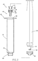
- the safety syringe 10 comprises a barrel 20, a needle holder 30, an interlocking seat 40, and a plunger 50.
- the barrel 20 comprises a barrel body 21, an opening 22 located in a top end of the barrel body 21, a tubular neck 23 forwardly extending from an opposing bottom end of the barrel body 21, and a positioning groove 24 extending around an inside wall of the tubular neck 23.
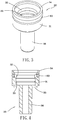
- the needle holder 30 is adapted for the mounting of a needlestick (not shown), comprising a first ring wall 31, a first internal flange 32 and a second internal flange 33.
- the first internal flange 32 and the second internal flange 33 extend around an inner surface of the first ring wall 31 and spaced from each other at a distance. Further, the inner diameter of the first internal flange 32 is smaller than the inner diameter of the second internal flange 33. Further, a leak-proof gasket ring 60 is mounted around the outer surface of the first ring wall 31.
- the needle holder 30 further comprises a first positioning flange 34 radially outwardly extending from a top end of the first ring wall 31 and having an outer diameter larger than the outer diameter of the first internal flange 32 and the outer diameter of the second internal flange 33, an end wall 35 located at an opposing bottom end of the first ring wall 31 and spaced from the second internal flange 33 at a distance smaller than the distance between the end wall 35 and the first internal flange 32, and a tubular wall 36 outwardly extending from the end wall 35 in direction away from the first ring wall 31.
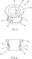
- the interlocking seat 40 comprises a second ring wall 41, two slots 42 located in the second ring wall 41 at two opposite sides, an elastic flap 43 mounted in each slot 42, a second positioning flange 44 radially outwardly extending from a top end of the second ring wall 41, and a first external flange 45 extending around the outer surface of the second ring wall 41 at an opposing bottom end thereof.
- the outer diameter of the second positioning flange 44 is larger than the outer diameter of the first external flange 45.
- the outer diameter of the first external flange 45 is larger than the inner diameter of the first internal flange 32 of the needle holder 30.
- the needle holder 30 and the interlocking seat 40 When assembling the barrel 20, the needle holder 30 and the interlocking seat 40, as shown in FIGS. 4 , 6 , 7 and 7A , insert the needle holder 30 through the opening 22 of the barrel body 21 of the barrel 20 into the inside of the tubular neck 23 of the barrel 20 to expose the tubular wall 36 of the needle holder 30 to the outside of the tubular neck 23 of the barrel 20, then insert the interlocking seat 40 into the inside of the first ring wall 31 of the needle holder 30 to force the first external flange 45 into engagement with the second internal flange 33 of the needle holder 30.
- the second positioning flange 44 of the interlocking seat 40 is forced to push the first positioning flange 34 of the needle holder 30, thereby radially deforming the first positioning flange 34 of the needle holder 30 and forcing the first positioning flange 34 to engage into the positioning groove 24 of the barrel 20.
- the needle holder 30 can be firmly positioned in the tubular neck 23 of the barrel 20 to bear the pressure from the needlestick in the injection.
- the plunger 50 is inserted through the opening 22 of the barrel 20 into the inside of the barrel body 21, and can be reciprocated up and down in the barrel 20 by an external force. Further, as shown in FIGS. 1 and 1A , the plunger 50 has a bottom end thereof mounted with an elastic stopper 62. Further, the plunger 50 comprises a pressing portion 51 located at the bottom end thereof and extending out of the elastic stopper 62, and a second external flange 52 extending around the periphery of the pressing portion 51. The outer diameter of the second external flange 52 is larger than the distance between the two elastic flaps 43 of the interlocking seat 40. Further, the elastic stopper 62 comprises a buffer portion 63 protruded from a top end thereof.
- the buffer portion 63 is an annular flange located at the top end of the elastic stopper 62.
- this configuration is not a limitation.
- the buffer portion 63 can be made in the form of a post or any other structure capable of providing a buffering effect.
- the pressing portion 51 of the plunger 50 When pushing the plunger 50 forwards in an injection operation, the pressing portion 51 of the plunger 50 will be inserted into the inside of the second ring wall 41 of the interlocking seat 40, and the elastic flaps 43 of the interlocking seat 40 will be stretched open by the second external flange 52 of the plunger 50 for enabling the pressing portion 51 to pass over.
- the elastic flaps 43 of the interlocking seat 40 After the second external flange 52 passed over the elastic flaps 43 of the interlocking seat 40, the elastic flaps 43 of the interlocking seat 40 immediately return to their former shape subject to their elastic restoring force and are stopped against the second external flange 52 at the pressing portion 51 of the plunger 50, as shown in FIG. 7 .
- the second external flange 52 at the pressing portion 51 of the plunger 50 When continuously pushing the plunger 50 forwards, the second external flange 52 at the pressing portion 51 of the plunger 50 will be stopped against the first external flange 45 of the interlocking seat 40, and the residual fluid in the needle holder 30 will be minimized subject to the movement of the pressing portion 51 of the plunger 50, thereby finishing the injection.
- the buffer portion 63 at the top end of the elastic stopper 62 provides a buffer stroke so that when the buffer portion 63 is stopped at the second positioning flange 44, it needs to push the plunger 50 further forward to force the second external flange 52 into engagement with the elastic flaps 43.
- the medical personnel can pull the plunger 50 backwards.
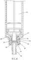
- the plunger 50 is pulled backward, as shown in FIG. 8 , the interlocking seat 40 and the plunger 50 are engaged together, and the needle holder 30 is secured to the barrel 20, and therefore the first external flange 45 of the interlocking seat 40 will be disengaged from the second internal flange 33 of the needle holder 30 at first upon a backward movement of the plunger 50, enabling the interlocking seat 40 to be moved in direction away from the needle holder 30 to the extent where the first external flange 45 of the interlocking seat 40 is forced into engagement with the first internal flange 32 of the needle holder 30.
- the second positioning flange 44 of the interlocking seat 40 is disengaged from the first positioning flange 34 of the needle holder 30 to release the push force of the first positioning flange 34 of the needle holder 30, and thus the needle holder 30 is unlocked.
- the needle holder 40 with the attached needlestick can be pulled backwardly away from the tubular neck 23 of the barrel 20 into the inside of the barrel body 21 of the barrel 20 and received therein.
- the structural stability of the needle holder 30 is maintained and the needle holder 30 will not fall from the barrel 20 accidentally during the injection operation and the amount of residual fluid can be minimized to avoid waste.
- the needle holder 30 with the attached needlestick can be accurately carried by the interlocking seat 40 backwardly into the inside of the barrel 20 when the plunger 50 is pulled back, preventing needlestick injuries and facilitating implementation of single-use.
- the plunger 50 is pushed to the end in the injection, the user needs to apply a further push force to the plunger 50 so that the interlocking seat 40 can be pulled backwardly into the inside of the barrel 20.
- This two-stage force application design avoids accidental engagement between the interlocking seat 40 and the plunger 50 due to the use of unnecessarily excessive force during the injection.
Description
- The present invention relates to medical equipment and more particularly, to a safety syringe.
- A syringe is an implement adapted for use with a needlestick to inject a liquid medicine, blood or other nutrient solution into the human body. After the injection, the needlestick has the human blood adhered thereto. Therefore, the needlestick should be disposed of safety after the use, avoiding medicare personnel or other persons from being injured by the needlestick accidentally.
- The most commonly applied method for disposal of a used needlestick is to insert the needlestick into a needlestick cap after its use. However, when the medicare personnel inserts the needlestick into a needlestick cap, the hand of the medicare personnel can be injured by the needlestick accidentally due to their own carelessness or by other external forces, increasing the risk of infection.
-
US 6,488,657 discloses a needle holder positioning structure for a safety syringe in accordance with the preamble of claim 1. In use retraction of the needle holder is complicated and requires much space and high retraction forces due to friction between needle holder and the structure's barrel, thus being inefficient and insecure. - The present invention has been accomplished under the circumstances in view. It is the main object of the present invention to provide a safety syringe, which is easy to operate and can accurately receive the needlestick after its use, reducing the risk of accidental needlestick injuries.
- To achieve this and other objects of the present invention, a safety syringe comprises a barrel, a needle holder, an interlocking seat, and a plunger according to claim 1. The barrel comprises a barrel body, a tubular neck outwardly extending from one end of the barrel body, and a positioning groove extending around an inside wall of the tubular neck. The needle holder is detachably mounted in the tubular neck of the barrel, comprising a first ring wall, and a first positioning flange located at one end of the first ring wall and elastically engaged in the positioning groove inside the tubular neck of the barrel. The interlocking seat is axially movably mounted in the first ring wall of the needle holder, comprising a second ring wall. The plunger is axially movably mounted in the barrel body of the barrel, comprising a pressing portion inserted into the inside of the second ring wall of the interlocking seat. The present invention is characterized in that said needle holder further comprises a first internal flange extending around an inner surface of said first ring wall; in that said interlocking seat further comprises at least one elastic flap mounted in said second ring wall, and a first external flange extending around an outer surface of one end of said second ring wall for engagement with said first internal flange of said needle holder by means of an axial movement of said interlocking seat; and in that said plunger further comprises a second external flange located at an outer surface of said pressing portion and adapted for engagement with said elastic flaps of said interlocking seat upon an axial movement of said plunger relative to said barrel. Thus, the interlocking seat can be moved by a pull force of the plunger in direction away from the needle holder to carry the needle holder and an attached needlestick into the inside of the barrel.
- Preferably, the needle holder further comprises an end wall located at an opposite end of the first ring wall, and a second internal flange extending around an inner surface of the first ring wall. The second internal flange is disposed between the first internal flange and the end wall. Thus, when mounting the interlocking seat in the needle holder, the first external flange can be forced into engagement with the second internal flange to achieve a good positioning effect.
- Preferably, the interlocking seat comprises two slots located in the second ring wall, and two elastic flaps respectively mounted in the two slots. Further, the distance between these two elastic flaps is smaller than the outer diameter of the second external flange at the pressing portion of the plunger. Thus, during the injection, the two elastic flaps of the interlocking seat are forced to expand by the second external flange at the pressing portion of the plunger for enabling the pressing portion to pass over. After the second external flange passed over the elastic flaps of the interlocking seat, the elastic flaps of the interlocking seat immediately return to their former shape and are stopped against the second external flange at the pressing portion of the plunger.
- Preferably, the interlocking seat further comprises a second positioning flange located at an opposite end of the second ring wall and stopped against the first positioning flange of the needle holder to elastically deform the first positioning flange of the needle holder and to force it into the positioning groove of the barrel.
- Preferably, the plunger has a bottom end thereof mounted with an elastic stopper. The elastic stopper comprises a buffer portion at a top end thereof. Thus, when the buffer portion is stopped at the second positioning flange, a further force should be employed to force the elastic flaps into engagement with the second external flange.
- Other advantages and features of the present invention will be fully understood by reference to the following specification in conjunction with the accompanying drawings, in which like reference signs denote like components of structure.
-
-
FIG. 1 is a sectional assembly view of a safety syringe in accordance with the present invention. -
FIG. 1A is an enlarged view of a part ofFIG. 1 , illustrating the configuration of the buffer portion at the elastic stopper. -
FIG. 2 is a sectional exploded view of the safety syringe in accordance with the present invention. -
FIG. 3 is an elevational view of the needle holder in accordance with the present invention. -
FIG. 4 is a sectional view of the needle holder in accordance with the present invention. -
FIG. 5 is an elevational view of the interlocking seat in accordance with the present invention. -
FIG. 6 is a sectional view of the interlocking seat in accordance with the present invention. -
FIG. 7 is a sectional view of a part of the present invention, illustrating the first external flange of the interlocking seat engaged with the second internal flange of the needle holder. -
FIG. 7A is an enlarged view of a part ofFIG. 7 , illustrating the buffer portion stopped at the second positioning flange. -
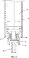
FIG. 8 is similar toFIG. 7 , illustrating the first external flange of the interlocking seat engaged with the first internal flange of the needle holder. -
FIG. 9 is similar toFIG. 8 , illustrating the needle holder moved with the interlocking seat to the inside of the barrel. - Referring to
FIGS. 1 and2 , asafety syringe 10 in accordance with the present invention is shown. Thesafety syringe 10 comprises abarrel 20, aneedle holder 30, an interlockingseat 40, and aplunger 50. - The
barrel 20 comprises abarrel body 21, an opening 22 located in a top end of thebarrel body 21, atubular neck 23 forwardly extending from an opposing bottom end of thebarrel body 21, and apositioning groove 24 extending around an inside wall of thetubular neck 23. - Referring to
FIGS. 3 and 4 , theneedle holder 30 is adapted for the mounting of a needlestick (not shown), comprising afirst ring wall 31, a firstinternal flange 32 and a secondinternal flange 33. The firstinternal flange 32 and the secondinternal flange 33 extend around an inner surface of thefirst ring wall 31 and spaced from each other at a distance. Further, the inner diameter of the firstinternal flange 32 is smaller than the inner diameter of the secondinternal flange 33. Further, a leak-proof gasket ring 60 is mounted around the outer surface of thefirst ring wall 31. Theneedle holder 30 further comprises afirst positioning flange 34 radially outwardly extending from a top end of thefirst ring wall 31 and having an outer diameter larger than the outer diameter of the firstinternal flange 32 and the outer diameter of the secondinternal flange 33, anend wall 35 located at an opposing bottom end of thefirst ring wall 31 and spaced from the secondinternal flange 33 at a distance smaller than the distance between theend wall 35 and the firstinternal flange 32, and atubular wall 36 outwardly extending from theend wall 35 in direction away from thefirst ring wall 31. - Referring to
FIGS. 5 and 6 , the interlockingseat 40 comprises asecond ring wall 41, twoslots 42 located in thesecond ring wall 41 at two opposite sides, anelastic flap 43 mounted in eachslot 42, asecond positioning flange 44 radially outwardly extending from a top end of thesecond ring wall 41, and a firstexternal flange 45 extending around the outer surface of thesecond ring wall 41 at an opposing bottom end thereof. Further, the outer diameter of thesecond positioning flange 44 is larger than the outer diameter of the firstexternal flange 45. Further, the outer diameter of the firstexternal flange 45 is larger than the inner diameter of the firstinternal flange 32 of theneedle holder 30. - When assembling the
barrel 20, theneedle holder 30 and the interlockingseat 40, as shown inFIGS. 4 ,6 ,7 and 7A , insert theneedle holder 30 through the opening 22 of thebarrel body 21 of thebarrel 20 into the inside of thetubular neck 23 of thebarrel 20 to expose thetubular wall 36 of theneedle holder 30 to the outside of thetubular neck 23 of thebarrel 20, then insert the interlockingseat 40 into the inside of thefirst ring wall 31 of theneedle holder 30 to force the firstexternal flange 45 into engagement with the secondinternal flange 33 of theneedle holder 30. At this time, thesecond positioning flange 44 of the interlockingseat 40 is forced to push thefirst positioning flange 34 of theneedle holder 30, thereby radially deforming thefirst positioning flange 34 of theneedle holder 30 and forcing thefirst positioning flange 34 to engage into thepositioning groove 24 of thebarrel 20. Based on this design, theneedle holder 30 can be firmly positioned in thetubular neck 23 of thebarrel 20 to bear the pressure from the needlestick in the injection. - The
plunger 50 is inserted through the opening 22 of thebarrel 20 into the inside of thebarrel body 21, and can be reciprocated up and down in thebarrel 20 by an external force. Further, as shown inFIGS. 1 and 1A , theplunger 50 has a bottom end thereof mounted with anelastic stopper 62. Further, theplunger 50 comprises apressing portion 51 located at the bottom end thereof and extending out of theelastic stopper 62, and a secondexternal flange 52 extending around the periphery of thepressing portion 51. The outer diameter of the secondexternal flange 52 is larger than the distance between the twoelastic flaps 43 of the interlockingseat 40. Further, theelastic stopper 62 comprises abuffer portion 63 protruded from a top end thereof. In this embodiment, thebuffer portion 63 is an annular flange located at the top end of theelastic stopper 62. However, this configuration is not a limitation. Alternatively, thebuffer portion 63 can be made in the form of a post or any other structure capable of providing a buffering effect. - When pushing the
plunger 50 forwards in an injection operation, thepressing portion 51 of theplunger 50 will be inserted into the inside of thesecond ring wall 41 of the interlockingseat 40, and theelastic flaps 43 of the interlockingseat 40 will be stretched open by the secondexternal flange 52 of theplunger 50 for enabling thepressing portion 51 to pass over. After the secondexternal flange 52 passed over theelastic flaps 43 of the interlockingseat 40, theelastic flaps 43 of the interlockingseat 40 immediately return to their former shape subject to their elastic restoring force and are stopped against the secondexternal flange 52 at thepressing portion 51 of theplunger 50, as shown inFIG. 7 . When continuously pushing theplunger 50 forwards, the secondexternal flange 52 at thepressing portion 51 of theplunger 50 will be stopped against the firstexternal flange 45 of the interlockingseat 40, and the residual fluid in theneedle holder 30 will be minimized subject to the movement of thepressing portion 51 of theplunger 50, thereby finishing the injection. During engagement between the interlockingseat 40 and theplunger 50, thebuffer portion 63 at the top end of theelastic stopper 62 provides a buffer stroke so that when thebuffer portion 63 is stopped at thesecond positioning flange 44, it needs to push theplunger 50 further forward to force the secondexternal flange 52 into engagement with the elastic flaps 43. - After injection, the medical personnel can pull the
plunger 50 backwards. At the time theplunger 50 is pulled backward, as shown inFIG. 8 , the interlockingseat 40 and theplunger 50 are engaged together, and theneedle holder 30 is secured to thebarrel 20, and therefore the firstexternal flange 45 of the interlockingseat 40 will be disengaged from the secondinternal flange 33 of theneedle holder 30 at first upon a backward movement of theplunger 50, enabling the interlockingseat 40 to be moved in direction away from theneedle holder 30 to the extent where the firstexternal flange 45 of the interlockingseat 40 is forced into engagement with the firstinternal flange 32 of theneedle holder 30. At this time, thesecond positioning flange 44 of the interlockingseat 40 is disengaged from thefirst positioning flange 34 of theneedle holder 30 to release the push force of thefirst positioning flange 34 of theneedle holder 30, and thus theneedle holder 30 is unlocked. Under this condition, as shown inFIG. 9 , when continuously pulling theplunger 50 backwards, due to the engagement relationship between the interlockingseat 40 and theneedle holder 30, theneedle holder 40 with the attached needlestick can be pulled backwardly away from thetubular neck 23 of thebarrel 20 into the inside of thebarrel body 21 of thebarrel 20 and received therein. - In conclusion, subject to the arrangement and engagement relationship among the
needle holder 30, interlockingseat 40 andplunger 50 of thesafety syringe 10, the structural stability of theneedle holder 30 is maintained and theneedle holder 30 will not fall from thebarrel 20 accidentally during the injection operation and the amount of residual fluid can be minimized to avoid waste. After the injection, theneedle holder 30 with the attached needlestick can be accurately carried by the interlockingseat 40 backwardly into the inside of thebarrel 20 when theplunger 50 is pulled back, preventing needlestick injuries and facilitating implementation of single-use. Further, after theplunger 50 is pushed to the end in the injection, the user needs to apply a further push force to theplunger 50 so that the interlockingseat 40 can be pulled backwardly into the inside of thebarrel 20. This two-stage force application design avoids accidental engagement between the interlockingseat 40 and theplunger 50 due to the use of unnecessarily excessive force during the injection.
Claims (8)
- A safety syringe (10) comprising:a barrel (20) comprising a barrel body (21), a tubular neck (23) outwardly extending from one end of said barrel body (21), and a positioning groove (24) extending around an inside wall of said tubular neck (23);a needle holder (30) detachably mounted in said tubular neck (23) of said barrel (20), said needle holder (30) comprising a first ring wall (31) and a first positioning flange (34) located at one end of said first ring wall (31) and elastically engaged in said positioning groove (24) inside said tubular neck (23) of said barrel (20);an interlocking seat (40) axially movably mounted in said first ring wall (31) of said needle holder (30), said interlocking seat (40) comprising a second ring wall (41);a plunger (50) axially movably mounted in said barrel body (21) of said barrel (20), said plunger (50) comprising a pressing portion (51) inserted into the inside of said second ring wall (41) of said interlocking seat (40);characterized in that said needle holder (30) further comprises a first internal flange (32) extending around an inner surface of said first ring wall (31),in that said interlocking seat (40) further comprises at least one elastic flap (43) mounted in said second ring wall (41), and a first external flange (45) extending around an outer surface of one end of said second ring wall (41) for engagement with said first internal flange (32) of said needle holder (30) by means of an axial movement of said interlocking seat (40), andin that said plunger (50) further comprises a second external flange (52) located at an outer surface of said pressing portion (51) and adapted for engagement with said elastic flaps (43) of said interlocking seat (40) upon an axial movement of said plunger (50) relative to said barrel (20).
- The safety syringe (10) as claimed in claim 1, wherein said needle holder (30) further comprises a second internal flange (33) located at an inner surface of said first ring wall (31) for engagement with said first external flange (45) of said interlocking seat (40); said first internal flange (32) and said second internal flange (33) being spaced from each other at a predetermined distance; an inner diameter of said first internal flange (32) is smaller than an inner diameter of said second internal flange (33).
- The safety syringe (10) as claimed in claim 2, wherein said needle holder (30) further comprises an end wall (35) and a tubular wall (36), said end wall (35) being located at an opposite end of said first ring wall (31) remote from said first positioning flange (34), a distance between said end wall (35) and said second internal flange (33) being smaller than a distance between said end wall (35) and said first internal flange (32), said tubular wall (36) extending from one end of said end wall (35) to the outside of said tubular neck (23) of said barrel (20) in direction away from said first ring wall (31).
- The safety syringe (10) as claimed in claim 1, wherein said interlocking seat (40) further comprises at least one slot (42) located in said second ring wall (41); each said elastic flap (43) is located in one respective said slot (42).
- The safety syringe (10) as claimed in claim 4, wherein said interlocking seat (40) comprises two said slots (42) located in said second ring wall (41) at two opposite sides, each said slot (42) having one said elastic flap (43) located therein, a distance between the two said elastic flaps (43) being smaller than an outer diameter of said second external flange (52) at said pressing portion (51) of said plunger (50).
- The safety syringe (10) as claimed in claim 1, wherein said interlocking seat (40) further comprises a second positioning flange (44) located at an opposite end of said second ring wall (41) and stopped against said first positioning flange (34) of said needle holder (40).
- The safety syringe (10) as claimed in claim 6, wherein an outer diameter of said second positioning flange (44) of said interlocking seat (40) is larger than an outer diameter of said first positioning flange (34) of said needle holder (30); the outer diameter of said first positioning flange (34) of said needle holder (30) is larger than an outer diameter of said first external flange (45) of said interlocking seat (40).
- The safety syringe (10) as claimed in claim 1, wherein said plunger (50) has a bottom end thereof mounted with an elastic stopper (62), said elastic stopper (62) comprising a buffer portion (63) located at a top end thereof.
Applications Claiming Priority (1)
| Application Number | Priority Date | Filing Date | Title |
|---|---|---|---|
| TW102143887A TW201519926A (en) | 2013-11-29 | 2013-11-29 | Safety syringe |
Publications (2)
| Publication Number | Publication Date |
|---|---|
| EP2878324A1 EP2878324A1 (en) | 2015-06-03 |
| EP2878324B1 true EP2878324B1 (en) | 2017-04-19 |
Family
ID=52013853
Family Applications (1)
| Application Number | Title | Priority Date | Filing Date |
|---|---|---|---|
| EP14195373.7A Active EP2878324B1 (en) | 2013-11-29 | 2014-11-28 | Safety syringe |
Country Status (13)
| Country | Link |
|---|---|
| US (1) | US9636465B2 (en) |
| EP (1) | EP2878324B1 (en) |
| JP (1) | JP5993919B2 (en) |
| KR (1) | KR102370396B1 (en) |
| CN (1) | CN104667390B (en) |
| AU (1) | AU2014265017B2 (en) |
| BR (1) | BR102014029905B1 (en) |
| CA (1) | CA2870645C (en) |
| ES (1) | ES2633491T3 (en) |
| MY (1) | MY166659A (en) |
| PT (1) | PT2878324T (en) |
| RU (1) | RU2666264C2 (en) |
| TW (1) | TW201519926A (en) |
Families Citing this family (11)
| Publication number | Priority date | Publication date | Assignee | Title |
|---|---|---|---|---|
| CA2746283A1 (en) * | 2010-09-10 | 2012-03-10 | Sulzer Mixpac Ag | Childproof closure for a dispensing apparatus |
| US10169243B2 (en) | 2016-07-18 | 2019-01-01 | International Business Machines Corporation | Reducing over-purging of structures associated with address translation |
| US10176111B2 (en) | 2016-07-18 | 2019-01-08 | International Business Machines Corporation | Host page management using active guest page table indicators |
| US10180909B2 (en) | 2016-07-18 | 2019-01-15 | International Business Machines Corporation | Host-based resetting of active use of guest page table indicators |
| US10248573B2 (en) | 2016-07-18 | 2019-04-02 | International Business Machines Corporation | Managing memory used to back address translation structures |
| US10241924B2 (en) | 2016-07-18 | 2019-03-26 | International Business Machines Corporation | Reducing over-purging of structures associated with address translation using an array of tags |
| US10282305B2 (en) | 2016-07-18 | 2019-05-07 | International Business Machines Corporation | Selective purging of entries of structures associated with address translation in a virtualized environment |
| US10176110B2 (en) | 2016-07-18 | 2019-01-08 | International Business Machines Corporation | Marking storage keys to indicate memory used to back address translation structures |
| US10168902B2 (en) | 2016-07-18 | 2019-01-01 | International Business Machines Corporation | Reducing purging of structures associated with address translation |
| US10223281B2 (en) | 2016-07-18 | 2019-03-05 | International Business Machines Corporation | Increasing the scope of local purges of structures associated with address translation |
| EP3821925B1 (en) * | 2019-09-18 | 2024-03-20 | KAISHA PACKAGING Private Ltd. | Device for locking a plunger rod of a syringe after use and preventing re-use of the syringe, and syringe assembly |
Family Cites Families (17)
| Publication number | Priority date | Publication date | Assignee | Title |
|---|---|---|---|---|
| RU2065757C1 (en) * | 1991-02-20 | 1996-08-27 | Шейко Петр Андреевич | Expendable syringe |
| US6193687B1 (en) * | 2000-01-25 | 2001-02-27 | Pi-Chang Lo | Safety hypodermic syringe |
| US6423033B1 (en) * | 2001-03-02 | 2002-07-23 | Jin-Chou Tsai | Safety hypodermic syringe |
| US6488657B1 (en) * | 2001-09-21 | 2002-12-03 | M.K. Meditech Co., Ltd. | Needle holder positioning structure for safety hypodermic syringe |
| US6656165B2 (en) | 2001-10-26 | 2003-12-02 | Hsin Cheng Chen | Disposable safety syringe |
| US6752784B2 (en) * | 2002-07-30 | 2004-06-22 | Hsi-Chin Tsai | Labor efficient safety syringe |
| US20040122378A1 (en) | 2002-12-19 | 2004-06-24 | Fu-Yu Hsu | Safety hypodermic syringe |
| CN2782120Y (en) * | 2005-01-25 | 2006-05-24 | 林作钱 | Safety self-destroying disposable syringe |
| US7637890B2 (en) * | 2005-01-25 | 2009-12-29 | Zuoqian Lin | Safety self-destroying disposable syringe |
| TWM286674U (en) * | 2005-04-12 | 2006-02-01 | Yu-Yue Lin | Disposable safety syringe |
| TWM340060U (en) * | 2008-03-10 | 2008-09-11 | shu-ming Zhang | Improved safety syringe structure with retractable needle |
| TW201039877A (en) * | 2009-05-05 | 2010-11-16 | shu-ming Zhang | Retraction structure of safety syringe |
| TW201100133A (en) * | 2009-06-26 | 2011-01-01 | shu-ming Zhang | Retraction device of safe syringe |
| JP5714268B2 (en) * | 2010-08-26 | 2015-05-07 | テルモ株式会社 | Prefilled syringe |
| KR101282209B1 (en) * | 2012-06-01 | 2013-07-04 | 백우인 | Disposable safety syringe |
| TWM448282U (en) * | 2012-09-24 | 2013-03-11 | Wei jia qing | Safety self-destructive needle |
| TWM483802U (en) * | 2013-11-29 | 2014-08-11 | Zheng Bo Ren | Safety syringe |
-
2013
- 2013-11-29 TW TW102143887A patent/TW201519926A/en unknown
-
2014
- 2014-09-28 CN CN201410509530.9A patent/CN104667390B/en active Active
- 2014-11-10 JP JP2014227796A patent/JP5993919B2/en active Active
- 2014-11-10 CA CA2870645A patent/CA2870645C/en active Active
- 2014-11-18 AU AU2014265017A patent/AU2014265017B2/en active Active
- 2014-11-24 US US14/552,185 patent/US9636465B2/en active Active
- 2014-11-26 RU RU2014147628A patent/RU2666264C2/en active
- 2014-11-26 MY MYPI2014703521A patent/MY166659A/en unknown
- 2014-11-28 EP EP14195373.7A patent/EP2878324B1/en active Active
- 2014-11-28 KR KR1020140168009A patent/KR102370396B1/en active IP Right Grant
- 2014-11-28 ES ES14195373.7T patent/ES2633491T3/en active Active
- 2014-11-28 BR BR102014029905-0A patent/BR102014029905B1/en active IP Right Grant
- 2014-11-28 PT PT141953737T patent/PT2878324T/en unknown
Also Published As
| Publication number | Publication date |
|---|---|
| JP2015104665A (en) | 2015-06-08 |
| US9636465B2 (en) | 2017-05-02 |
| KR20150062997A (en) | 2015-06-08 |
| TWI488666B (en) | 2015-06-21 |
| JP5993919B2 (en) | 2016-09-14 |
| TW201519926A (en) | 2015-06-01 |
| ES2633491T3 (en) | 2017-09-21 |
| AU2014265017A1 (en) | 2015-06-18 |
| CN104667390B (en) | 2018-03-27 |
| MY166659A (en) | 2018-07-18 |
| EP2878324A1 (en) | 2015-06-03 |
| CA2870645A1 (en) | 2015-05-29 |
| BR102014029905B1 (en) | 2021-09-21 |
| US20150151056A1 (en) | 2015-06-04 |
| RU2666264C2 (en) | 2018-09-06 |
| KR102370396B1 (en) | 2022-03-03 |
| RU2014147628A3 (en) | 2018-06-21 |
| PT2878324T (en) | 2017-07-18 |
| CA2870645C (en) | 2021-09-21 |
| AU2014265017B2 (en) | 2018-05-17 |
| BR102014029905A2 (en) | 2016-05-24 |
| CN104667390A (en) | 2015-06-03 |
| RU2014147628A (en) | 2016-06-20 |
Similar Documents
| Publication | Publication Date | Title |
|---|---|---|
| EP2878324B1 (en) | Safety syringe | |
| US11241545B2 (en) | Retractable syringe with improved delivery efficiency and locking system | |
| CA2797207C (en) | Syringe barrel adapter and needle assembly | |
| TWI564049B (en) | Vaccination syringe | |
| US9636466B2 (en) | Prefilled retractable syringe, plunger and needle assembly | |
| EP2313135B1 (en) | A retractable syringe | |
| EP2776097B1 (en) | Improved retractable syringe needle | |
| US20210330886A1 (en) | Safety syringe | |
| TW201700119A (en) | Safe syringe for detaching needle by pushing capable of detaching needle from front end of barrel after usage to protect the medical personnel from being stabbed by used needle | |
| AU2014218378B2 (en) | Retractable syringe with improved delivery efficiency and locking system | |
| WO2019029122A1 (en) | Rapid and automatic syringe | |
| US20070262167A1 (en) | Disposable syringe |
Legal Events
| Date | Code | Title | Description |
|---|---|---|---|
| PUAI | Public reference made under article 153(3) epc to a published international application that has entered the european phase |
Free format text: ORIGINAL CODE: 0009012 |
|
| 17P | Request for examination filed |
Effective date: 20141128 |
|
| AK | Designated contracting states |
Kind code of ref document: A1 Designated state(s): AL AT BE BG CH CY CZ DE DK EE ES FI FR GB GR HR HU IE IS IT LI LT LU LV MC MK MT NL NO PL PT RO RS SE SI SK SM TR |
|
| AX | Request for extension of the european patent |
Extension state: BA ME |
|
| R17P | Request for examination filed (corrected) |
Effective date: 20151201 |
|
| RBV | Designated contracting states (corrected) |
Designated state(s): AL AT BE BG CH CY CZ DE DK EE ES FI FR GB GR HR HU IE IS IT LI LT LU LV MC MK MT NL NO PL PT RO RS SE SI SK SM TR |
|
| 17Q | First examination report despatched |
Effective date: 20160610 |
|
| REG | Reference to a national code |
Ref country code: DE Ref legal event code: R079 Ref document number: 602014008726 Country of ref document: DE Free format text: PREVIOUS MAIN CLASS: A61M0005320000 Ipc: A61M0005315000 |
|
| RIC1 | Information provided on ipc code assigned before grant |
Ipc: A61M 5/32 20060101ALI20161024BHEP Ipc: A61M 5/178 20060101ALI20161024BHEP Ipc: A61M 5/315 20060101AFI20161024BHEP Ipc: A61M 5/50 20060101ALI20161024BHEP Ipc: A61M 5/34 20060101ALI20161024BHEP |
|
| GRAP | Despatch of communication of intention to grant a patent |
Free format text: ORIGINAL CODE: EPIDOSNIGR1 |
|
| STAA | Information on the status of an ep patent application or granted ep patent |
Free format text: STATUS: GRANT OF PATENT IS INTENDED |
|
| INTG | Intention to grant announced |
Effective date: 20161207 |
|
| GRAS | Grant fee paid |
Free format text: ORIGINAL CODE: EPIDOSNIGR3 |
|
| GRAA | (expected) grant |
Free format text: ORIGINAL CODE: 0009210 |
|
| STAA | Information on the status of an ep patent application or granted ep patent |
Free format text: STATUS: THE PATENT HAS BEEN GRANTED |
|
| AK | Designated contracting states |
Kind code of ref document: B1 Designated state(s): AL AT BE BG CH CY CZ DE DK EE ES FI FR GB GR HR HU IE IS IT LI LT LU LV MC MK MT NL NO PL PT RO RS SE SI SK SM TR |
|
| REG | Reference to a national code |
Ref country code: GB Ref legal event code: FG4D |
|
| REG | Reference to a national code |
Ref country code: CH Ref legal event code: EP |
|
| REG | Reference to a national code |
Ref country code: AT Ref legal event code: REF Ref document number: 885343 Country of ref document: AT Kind code of ref document: T Effective date: 20170515 |
|
| REG | Reference to a national code |
Ref country code: IE Ref legal event code: FG4D |
|
| REG | Reference to a national code |
Ref country code: DE Ref legal event code: R096 Ref document number: 602014008726 Country of ref document: DE |
|
| REG | Reference to a national code |
Ref country code: CH Ref legal event code: NV Representative=s name: ROMAN VUILLE, CH |
|
| REG | Reference to a national code |
Ref country code: PT Ref legal event code: SC4A Ref document number: 2878324 Country of ref document: PT Date of ref document: 20170718 Kind code of ref document: T Free format text: AVAILABILITY OF NATIONAL TRANSLATION Effective date: 20170712 |
|
| REG | Reference to a national code |
Ref country code: NL Ref legal event code: FP |
|
| REG | Reference to a national code |
Ref country code: SE Ref legal event code: TRGR |
|
| REG | Reference to a national code |
Ref country code: LT Ref legal event code: MG4D |
|
| REG | Reference to a national code |
Ref country code: AT Ref legal event code: MK05 Ref document number: 885343 Country of ref document: AT Kind code of ref document: T Effective date: 20170419 |
|
| REG | Reference to a national code |
Ref country code: ES Ref legal event code: FG2A Ref document number: 2633491 Country of ref document: ES Kind code of ref document: T3 Effective date: 20170921 |
|
| PG25 | Lapsed in a contracting state [announced via postgrant information from national office to epo] |
Ref country code: LT Free format text: LAPSE BECAUSE OF FAILURE TO SUBMIT A TRANSLATION OF THE DESCRIPTION OR TO PAY THE FEE WITHIN THE PRESCRIBED TIME-LIMIT Effective date: 20170419 Ref country code: AT Free format text: LAPSE BECAUSE OF FAILURE TO SUBMIT A TRANSLATION OF THE DESCRIPTION OR TO PAY THE FEE WITHIN THE PRESCRIBED TIME-LIMIT Effective date: 20170419 Ref country code: GR Free format text: LAPSE BECAUSE OF FAILURE TO SUBMIT A TRANSLATION OF THE DESCRIPTION OR TO PAY THE FEE WITHIN THE PRESCRIBED TIME-LIMIT Effective date: 20170720 Ref country code: HR Free format text: LAPSE BECAUSE OF FAILURE TO SUBMIT A TRANSLATION OF THE DESCRIPTION OR TO PAY THE FEE WITHIN THE PRESCRIBED TIME-LIMIT Effective date: 20170419 Ref country code: NO Free format text: LAPSE BECAUSE OF FAILURE TO SUBMIT A TRANSLATION OF THE DESCRIPTION OR TO PAY THE FEE WITHIN THE PRESCRIBED TIME-LIMIT Effective date: 20170719 |
|
| REG | Reference to a national code |
Ref country code: FR Ref legal event code: PLFP Year of fee payment: 4 |
|
| PG25 | Lapsed in a contracting state [announced via postgrant information from national office to epo] |
Ref country code: PL Free format text: LAPSE BECAUSE OF FAILURE TO SUBMIT A TRANSLATION OF THE DESCRIPTION OR TO PAY THE FEE WITHIN THE PRESCRIBED TIME-LIMIT Effective date: 20170419 Ref country code: BG Free format text: LAPSE BECAUSE OF FAILURE TO SUBMIT A TRANSLATION OF THE DESCRIPTION OR TO PAY THE FEE WITHIN THE PRESCRIBED TIME-LIMIT Effective date: 20170719 Ref country code: LV Free format text: LAPSE BECAUSE OF FAILURE TO SUBMIT A TRANSLATION OF THE DESCRIPTION OR TO PAY THE FEE WITHIN THE PRESCRIBED TIME-LIMIT Effective date: 20170419 Ref country code: IS Free format text: LAPSE BECAUSE OF FAILURE TO SUBMIT A TRANSLATION OF THE DESCRIPTION OR TO PAY THE FEE WITHIN THE PRESCRIBED TIME-LIMIT Effective date: 20170819 Ref country code: RS Free format text: LAPSE BECAUSE OF FAILURE TO SUBMIT A TRANSLATION OF THE DESCRIPTION OR TO PAY THE FEE WITHIN THE PRESCRIBED TIME-LIMIT Effective date: 20170419 |
|
| REG | Reference to a national code |
Ref country code: DE Ref legal event code: R097 Ref document number: 602014008726 Country of ref document: DE |
|
| PG25 | Lapsed in a contracting state [announced via postgrant information from national office to epo] |
Ref country code: DK Free format text: LAPSE BECAUSE OF FAILURE TO SUBMIT A TRANSLATION OF THE DESCRIPTION OR TO PAY THE FEE WITHIN THE PRESCRIBED TIME-LIMIT Effective date: 20170419 Ref country code: EE Free format text: LAPSE BECAUSE OF FAILURE TO SUBMIT A TRANSLATION OF THE DESCRIPTION OR TO PAY THE FEE WITHIN THE PRESCRIBED TIME-LIMIT Effective date: 20170419 Ref country code: CZ Free format text: LAPSE BECAUSE OF FAILURE TO SUBMIT A TRANSLATION OF THE DESCRIPTION OR TO PAY THE FEE WITHIN THE PRESCRIBED TIME-LIMIT Effective date: 20170419 Ref country code: RO Free format text: LAPSE BECAUSE OF FAILURE TO SUBMIT A TRANSLATION OF THE DESCRIPTION OR TO PAY THE FEE WITHIN THE PRESCRIBED TIME-LIMIT Effective date: 20170419 Ref country code: SK Free format text: LAPSE BECAUSE OF FAILURE TO SUBMIT A TRANSLATION OF THE DESCRIPTION OR TO PAY THE FEE WITHIN THE PRESCRIBED TIME-LIMIT Effective date: 20170419 |
|
| PLBE | No opposition filed within time limit |
Free format text: ORIGINAL CODE: 0009261 |
|
| STAA | Information on the status of an ep patent application or granted ep patent |
Free format text: STATUS: NO OPPOSITION FILED WITHIN TIME LIMIT |
|
| PG25 | Lapsed in a contracting state [announced via postgrant information from national office to epo] |
Ref country code: SM Free format text: LAPSE BECAUSE OF FAILURE TO SUBMIT A TRANSLATION OF THE DESCRIPTION OR TO PAY THE FEE WITHIN THE PRESCRIBED TIME-LIMIT Effective date: 20170419 |
|
| 26N | No opposition filed |
Effective date: 20180122 |
|
| PG25 | Lapsed in a contracting state [announced via postgrant information from national office to epo] |
Ref country code: SI Free format text: LAPSE BECAUSE OF FAILURE TO SUBMIT A TRANSLATION OF THE DESCRIPTION OR TO PAY THE FEE WITHIN THE PRESCRIBED TIME-LIMIT Effective date: 20170419 |
|
| PG25 | Lapsed in a contracting state [announced via postgrant information from national office to epo] |
Ref country code: MC Free format text: LAPSE BECAUSE OF FAILURE TO SUBMIT A TRANSLATION OF THE DESCRIPTION OR TO PAY THE FEE WITHIN THE PRESCRIBED TIME-LIMIT Effective date: 20170419 |
|
| PG25 | Lapsed in a contracting state [announced via postgrant information from national office to epo] |
Ref country code: LU Free format text: LAPSE BECAUSE OF NON-PAYMENT OF DUE FEES Effective date: 20171128 |
|
| REG | Reference to a national code |
Ref country code: BE Ref legal event code: MM Effective date: 20171130 |
|
| REG | Reference to a national code |
Ref country code: IE Ref legal event code: MM4A |
|
| PG25 | Lapsed in a contracting state [announced via postgrant information from national office to epo] |
Ref country code: MT Free format text: LAPSE BECAUSE OF NON-PAYMENT OF DUE FEES Effective date: 20171128 |
|
| PG25 | Lapsed in a contracting state [announced via postgrant information from national office to epo] |
Ref country code: IE Free format text: LAPSE BECAUSE OF NON-PAYMENT OF DUE FEES Effective date: 20171128 |
|
| PG25 | Lapsed in a contracting state [announced via postgrant information from national office to epo] |
Ref country code: BE Free format text: LAPSE BECAUSE OF NON-PAYMENT OF DUE FEES Effective date: 20171130 |
|
| PG25 | Lapsed in a contracting state [announced via postgrant information from national office to epo] |
Ref country code: HU Free format text: LAPSE BECAUSE OF FAILURE TO SUBMIT A TRANSLATION OF THE DESCRIPTION OR TO PAY THE FEE WITHIN THE PRESCRIBED TIME-LIMIT; INVALID AB INITIO Effective date: 20141128 |
|
| PG25 | Lapsed in a contracting state [announced via postgrant information from national office to epo] |
Ref country code: CY Free format text: LAPSE BECAUSE OF FAILURE TO SUBMIT A TRANSLATION OF THE DESCRIPTION OR TO PAY THE FEE WITHIN THE PRESCRIBED TIME-LIMIT Effective date: 20170419 |
|
| PG25 | Lapsed in a contracting state [announced via postgrant information from national office to epo] |
Ref country code: MK Free format text: LAPSE BECAUSE OF FAILURE TO SUBMIT A TRANSLATION OF THE DESCRIPTION OR TO PAY THE FEE WITHIN THE PRESCRIBED TIME-LIMIT Effective date: 20170419 |
|
| REG | Reference to a national code |
Ref country code: DE Ref legal event code: R082 Ref document number: 602014008726 Country of ref document: DE Representative=s name: 2K PATENT- UND RECHTSANWAELTE PARTNERSCHAFT MB, DE |
|
| PG25 | Lapsed in a contracting state [announced via postgrant information from national office to epo] |
Ref country code: TR Free format text: LAPSE BECAUSE OF FAILURE TO SUBMIT A TRANSLATION OF THE DESCRIPTION OR TO PAY THE FEE WITHIN THE PRESCRIBED TIME-LIMIT Effective date: 20170419 |
|
| PG25 | Lapsed in a contracting state [announced via postgrant information from national office to epo] |
Ref country code: AL Free format text: LAPSE BECAUSE OF FAILURE TO SUBMIT A TRANSLATION OF THE DESCRIPTION OR TO PAY THE FEE WITHIN THE PRESCRIBED TIME-LIMIT Effective date: 20170419 |
|
| PGFP | Annual fee paid to national office [announced via postgrant information from national office to epo] |
Ref country code: NL Payment date: 20201119 Year of fee payment: 7 |
|
| PGFP | Annual fee paid to national office [announced via postgrant information from national office to epo] |
Ref country code: PT Payment date: 20201119 Year of fee payment: 7 Ref country code: SE Payment date: 20201123 Year of fee payment: 7 Ref country code: FI Payment date: 20201117 Year of fee payment: 7 |
|
| REG | Reference to a national code |
Ref country code: FI Ref legal event code: MAE |
|
| REG | Reference to a national code |
Ref country code: NL Ref legal event code: MM Effective date: 20211201 |
|
| PG25 | Lapsed in a contracting state [announced via postgrant information from national office to epo] |
Ref country code: SE Free format text: LAPSE BECAUSE OF NON-PAYMENT OF DUE FEES Effective date: 20211129 Ref country code: PT Free format text: LAPSE BECAUSE OF NON-PAYMENT OF DUE FEES Effective date: 20220530 |
|
| PG25 | Lapsed in a contracting state [announced via postgrant information from national office to epo] |
Ref country code: FI Free format text: LAPSE BECAUSE OF NON-PAYMENT OF DUE FEES Effective date: 20211128 |
|
| PG25 | Lapsed in a contracting state [announced via postgrant information from national office to epo] |
Ref country code: NL Free format text: LAPSE BECAUSE OF NON-PAYMENT OF DUE FEES Effective date: 20211201 |
|
| PGFP | Annual fee paid to national office [announced via postgrant information from national office to epo] |
Ref country code: GB Payment date: 20231123 Year of fee payment: 10 |
|
| PGFP | Annual fee paid to national office [announced via postgrant information from national office to epo] |
Ref country code: ES Payment date: 20231215 Year of fee payment: 10 |
|
| PGFP | Annual fee paid to national office [announced via postgrant information from national office to epo] |
Ref country code: IT Payment date: 20231130 Year of fee payment: 10 Ref country code: FR Payment date: 20231122 Year of fee payment: 10 Ref country code: DE Payment date: 20231129 Year of fee payment: 10 Ref country code: CH Payment date: 20231202 Year of fee payment: 10 |