EP2877991B1 - Direktionale geräuschmaskierung - Google Patents
Direktionale geräuschmaskierung Download PDFInfo
- Publication number
- EP2877991B1 EP2877991B1 EP13766697.0A EP13766697A EP2877991B1 EP 2877991 B1 EP2877991 B1 EP 2877991B1 EP 13766697 A EP13766697 A EP 13766697A EP 2877991 B1 EP2877991 B1 EP 2877991B1
- Authority
- EP
- European Patent Office
- Prior art keywords
- sound
- signal
- sub
- masking
- determining
- Prior art date
- Legal status (The legal status is an assumption and is not a legal conclusion. Google has not performed a legal analysis and makes no representation as to the accuracy of the status listed.)
- Active
Links
- 230000000873 masking effect Effects 0.000 title claims description 92
- 238000001228 spectrum Methods 0.000 claims description 45
- 230000003044 adaptive effect Effects 0.000 claims description 33
- 238000012545 processing Methods 0.000 claims description 33
- 238000000034 method Methods 0.000 claims description 32
- 238000001914 filtration Methods 0.000 claims description 17
- 238000004590 computer program Methods 0.000 claims description 2
- 208000009205 Tinnitus Diseases 0.000 description 18
- 231100000886 tinnitus Toxicity 0.000 description 18
- 210000003128 head Anatomy 0.000 description 13
- 238000010586 diagram Methods 0.000 description 9
- 230000005236 sound signal Effects 0.000 description 8
- 210000005069 ears Anatomy 0.000 description 6
- 230000004807 localization Effects 0.000 description 6
- 230000008447 perception Effects 0.000 description 4
- 238000004458 analytical method Methods 0.000 description 3
- 210000004556 brain Anatomy 0.000 description 3
- 210000003477 cochlea Anatomy 0.000 description 3
- 230000000694 effects Effects 0.000 description 3
- 230000003935 attention Effects 0.000 description 2
- 230000019771 cognition Effects 0.000 description 2
- 238000002474 experimental method Methods 0.000 description 2
- 230000000415 inactivating effect Effects 0.000 description 2
- 239000011159 matrix material Substances 0.000 description 2
- 238000012544 monitoring process Methods 0.000 description 2
- 238000005316 response function Methods 0.000 description 2
- 230000003595 spectral effect Effects 0.000 description 2
- 241000167854 Bourreria succulenta Species 0.000 description 1
- 101000822695 Clostridium perfringens (strain 13 / Type A) Small, acid-soluble spore protein C1 Proteins 0.000 description 1
- 101000655262 Clostridium perfringens (strain 13 / Type A) Small, acid-soluble spore protein C2 Proteins 0.000 description 1
- 101000655256 Paraclostridium bifermentans Small, acid-soluble spore protein alpha Proteins 0.000 description 1
- 101000655264 Paraclostridium bifermentans Small, acid-soluble spore protein beta Proteins 0.000 description 1
- 208000003443 Unconsciousness Diseases 0.000 description 1
- 230000005534 acoustic noise Effects 0.000 description 1
- 238000013459 approach Methods 0.000 description 1
- 238000003491 array Methods 0.000 description 1
- 230000005540 biological transmission Effects 0.000 description 1
- 235000019693 cherries Nutrition 0.000 description 1
- 230000001934 delay Effects 0.000 description 1
- 230000001419 dependent effect Effects 0.000 description 1
- 238000000586 desensitisation Methods 0.000 description 1
- 230000001066 destructive effect Effects 0.000 description 1
- 230000009429 distress Effects 0.000 description 1
- 229940079593 drug Drugs 0.000 description 1
- 239000003814 drug Substances 0.000 description 1
- 210000000883 ear external Anatomy 0.000 description 1
- 210000003027 ear inner Anatomy 0.000 description 1
- 239000000284 extract Substances 0.000 description 1
- 239000012530 fluid Substances 0.000 description 1
- 238000005259 measurement Methods 0.000 description 1
- 230000001537 neural effect Effects 0.000 description 1
- 230000003287 optical effect Effects 0.000 description 1
- 238000011160 research Methods 0.000 description 1
- 230000004044 response Effects 0.000 description 1
- 230000010332 selective attention Effects 0.000 description 1
- 230000008054 signal transmission Effects 0.000 description 1
- 230000000638 stimulation Effects 0.000 description 1
- 210000005010 torso Anatomy 0.000 description 1
- 230000000007 visual effect Effects 0.000 description 1
Images
Classifications
-
- G—PHYSICS
- G10—MUSICAL INSTRUMENTS; ACOUSTICS
- G10K—SOUND-PRODUCING DEVICES; METHODS OR DEVICES FOR PROTECTING AGAINST, OR FOR DAMPING, NOISE OR OTHER ACOUSTIC WAVES IN GENERAL; ACOUSTICS NOT OTHERWISE PROVIDED FOR
- G10K11/00—Methods or devices for transmitting, conducting or directing sound in general; Methods or devices for protecting against, or for damping, noise or other acoustic waves in general
- G10K11/16—Methods or devices for protecting against, or for damping, noise or other acoustic waves in general
- G10K11/175—Methods or devices for protecting against, or for damping, noise or other acoustic waves in general using interference effects; Masking sound
- G10K11/1752—Masking
- G10K11/1754—Speech masking
-
- H—ELECTRICITY
- H04—ELECTRIC COMMUNICATION TECHNIQUE
- H04K—SECRET COMMUNICATION; JAMMING OF COMMUNICATION
- H04K3/00—Jamming of communication; Counter-measures
- H04K3/40—Jamming having variable characteristics
- H04K3/41—Jamming having variable characteristics characterized by the control of the jamming activation or deactivation time
-
- H—ELECTRICITY
- H04—ELECTRIC COMMUNICATION TECHNIQUE
- H04K—SECRET COMMUNICATION; JAMMING OF COMMUNICATION
- H04K3/00—Jamming of communication; Counter-measures
- H04K3/40—Jamming having variable characteristics
- H04K3/42—Jamming having variable characteristics characterized by the control of the jamming frequency or wavelength
-
- H—ELECTRICITY
- H04—ELECTRIC COMMUNICATION TECHNIQUE
- H04K—SECRET COMMUNICATION; JAMMING OF COMMUNICATION
- H04K3/00—Jamming of communication; Counter-measures
- H04K3/40—Jamming having variable characteristics
- H04K3/43—Jamming having variable characteristics characterized by the control of the jamming power, signal-to-noise ratio or geographic coverage area
-
- H—ELECTRICITY
- H04—ELECTRIC COMMUNICATION TECHNIQUE
- H04K—SECRET COMMUNICATION; JAMMING OF COMMUNICATION
- H04K3/00—Jamming of communication; Counter-measures
- H04K3/40—Jamming having variable characteristics
- H04K3/45—Jamming having variable characteristics characterized by including monitoring of the target or target signal, e.g. in reactive jammers or follower jammers for example by means of an alternation of jamming phases and monitoring phases, called "look-through mode"
-
- H—ELECTRICITY
- H04—ELECTRIC COMMUNICATION TECHNIQUE
- H04K—SECRET COMMUNICATION; JAMMING OF COMMUNICATION
- H04K3/00—Jamming of communication; Counter-measures
- H04K3/80—Jamming or countermeasure characterized by its function
- H04K3/82—Jamming or countermeasure characterized by its function related to preventing surveillance, interception or detection
- H04K3/825—Jamming or countermeasure characterized by its function related to preventing surveillance, interception or detection by jamming
-
- G—PHYSICS
- G10—MUSICAL INSTRUMENTS; ACOUSTICS
- G10K—SOUND-PRODUCING DEVICES; METHODS OR DEVICES FOR PROTECTING AGAINST, OR FOR DAMPING, NOISE OR OTHER ACOUSTIC WAVES IN GENERAL; ACOUSTICS NOT OTHERWISE PROVIDED FOR
- G10K2210/00—Details of active noise control [ANC] covered by G10K11/178 but not provided for in any of its subgroups
- G10K2210/10—Applications
- G10K2210/111—Directivity control or beam pattern
-
- G—PHYSICS
- G10—MUSICAL INSTRUMENTS; ACOUSTICS
- G10K—SOUND-PRODUCING DEVICES; METHODS OR DEVICES FOR PROTECTING AGAINST, OR FOR DAMPING, NOISE OR OTHER ACOUSTIC WAVES IN GENERAL; ACOUSTICS NOT OTHERWISE PROVIDED FOR
- G10K2210/00—Details of active noise control [ANC] covered by G10K11/178 but not provided for in any of its subgroups
- G10K2210/30—Means
- G10K2210/301—Computational
- G10K2210/3028—Filtering, e.g. Kalman filters or special analogue or digital filters
-
- H—ELECTRICITY
- H04—ELECTRIC COMMUNICATION TECHNIQUE
- H04K—SECRET COMMUNICATION; JAMMING OF COMMUNICATION
- H04K2203/00—Jamming of communication; Countermeasures
- H04K2203/10—Jamming or countermeasure used for a particular application
- H04K2203/12—Jamming or countermeasure used for a particular application for acoustic communication
-
- H—ELECTRICITY
- H04—ELECTRIC COMMUNICATION TECHNIQUE
- H04K—SECRET COMMUNICATION; JAMMING OF COMMUNICATION
- H04K2203/00—Jamming of communication; Countermeasures
- H04K2203/30—Jamming or countermeasure characterized by the infrastructure components
- H04K2203/32—Jamming or countermeasure characterized by the infrastructure components including a particular configuration of antennas
-
- H—ELECTRICITY
- H04—ELECTRIC COMMUNICATION TECHNIQUE
- H04K—SECRET COMMUNICATION; JAMMING OF COMMUNICATION
- H04K2203/00—Jamming of communication; Countermeasures
- H04K2203/30—Jamming or countermeasure characterized by the infrastructure components
- H04K2203/34—Jamming or countermeasure characterized by the infrastructure components involving multiple cooperating jammers
Definitions
- the invention relates to a system configured for masking sound incident on a person.
- the invention also relates to a signal-processing sub-system for use in a system of the invention, to a method of masking sound incident on a person, and to control software for configuring a computer to carry out a method of the invention.
- Sound masking is the addition of natural or artificial sound (such as white noise) into an environment to cover up unwanted sound. This is in contrast to the technique of active noise control. Sound masking reduces or eliminates awareness of pre-existing sounds in a given environment and can make the environment more comfortable. For example, devices are commercially available for being installed in a room in order to mask sounds that otherwise might interfere with a person's working or sleeping in the room.
- Sound masking devices are commercially available that produce stationary acoustic noise in a relatively wide frequency band to reduce the chance that a user will get awakened during his/her sleep as a result of ambient sounds.
- a microphone is used to capture the potentially disturbing sound for subjecting the potentially disturbing sound to an analysis in order to adjust the masking sound to the level of the intensity of the disturbing sound and to the spectral characteristics of the disturbing sound.
- the commercially available sound masking devices typically use a single loudspeaker to reproduce a sound in a relatively wide frequency-band, e.g., white noise.
- Some of the commercially available products come with a headphone connection, so that the masking sound does not disturb nearby persons in operational use of the product.
- the sound reproduced over the headphones is often only a duplication of the single channel.
- US 2013/0170655 A1 describes a sound masking system with a line of microphones and a line of loudspeakers. A position of a speaker is detected in response to the sound of the speaker's voice which is captured by the microphones. Delays for each of the loudspeakers are controlled such that sound from the loudspeakers arrives at a receiving person in the direction of the speaker whose voice is to be masked.
- US 2013/170662 A1 describes a sound masking system which picks up a sound with a microphone, extracts an acoustic feature amount, and outputs a masking sound corresponding to the acoustic feature amount extracted.
- An echo cancelling section is used to remove echo from the picked-up sound.
- the inventors have realized that the commercially available sound masking systems do not take directionality of the undesired sounds into account.
- the inventors now have turned this around and propose a deliberate sound masking scenario wherein an undesired sound is masked by an artificially generated noise that is controlled so as to have substantially the same direction of incidence on a person who is to be acoustically disturbed as little as possible.
- the inventors propose a signal-processing sub-system configured for masking a sound incident on a person, as defined by appended claim 1, and a system for masking a sound incident on a person, as defined by appended claim 2.
- the power attribute of the captured incident sound is determined so as to control a spectrum of the masking sound
- the directional attribute is determined in order to generate the masking sound that, when perceived by the person, appears to be coming from a direction similar to the direction of incidence of the incident sound so as to make the masking more efficient.
- the human ear processes sounds in parallel in the sense that the ear processes different spectral components simultaneously.
- the cochlea of the inner ear appears to act as a spectrum analyzer for performing a frequency analysis of the incoming sound and is often modeled in psychoacoustics as a bank of stagger-tuned, overlapping auditory band-pass filters.
- the cochlea is a dynamic system wherein the characteristic parameters of each band-pass filter, e.g., the filter's center frequency (at its peak), bandwidth and gain, are capable of being modified under unconscious control.
- the power attribute as determined comprises a respective indication representative of a respective frequency spectrum in a respective one of a plurality of frequency bands. Accordingly, the embodiment of the system can mask in parallel different incident sounds emitted at the same time by different sources at different locations and having different frequency spectra.
- the microphone sub-system supplies a first signal representative of the sound captured.
- the signal-processing sub-system supplies a second signal for control of the loudspeaker sub-system.
- the system comprises an adaptive filtering sub-system operative to reduce a contribution from the masking sound, present in the captured sound, to the second signal.
- the adaptive filtering system comprises an adaptive filter and a subtractor.
- the adaptive filter has a filter input for receiving the second signal and a filter output for supplying a filtered version of the second signal.
- the subtractor has a first subtractor input for receiving the first signal, a second subtractor input for receiving the filtered version of the second signal, and a subtractor output for supplying a third signal to the signal-processing sub-system that is representative of a difference between the first signal and the filtered version of the second signal.
- the adaptive filter has a control input for receiving the third signal for control of one or more filter coefficients of the adaptive filter.
- the sound captured by the microphone sub-system comprise the sound to be masked as well as the masking sound.
- the adaptive filtering sees to it that the masking sound as captured is substantially prevented from affecting the generation of the masking sound itself.
- the signal-processing sub-system comprises a spatial analyzer for determining the directional attribute, and wherein the spatial analyzer is operative to determine the directional attribute based on determining a quantity representative of at least one of: an interaural time difference (ITD) and an interaural level difference (ILD).
- ITD interaural time difference
- ILD interaural level difference
- interaural time difference ITD
- interaural level difference ILD
- beamforming is a signal-processing technique used in sensor arrays for directional signal transmission or reception. This is achieved by combining elements in the array in such a way that signals at particular angles experience constructive interference while others experience destructive interference. Beamforming can be used at both the transmitting and receiving ends in order to achieve spatial selectivity. For more background see, e.g., " Beamforming: A versatile approach to spatial filtering", B.D.V. Veen and K.M. Buckley, IEEE ASSP Magazine, April 1988, pp. 4-24 .
- a further embodiment of the system of the invention comprises a sound classifier that is operative to selectively remove a pre-determined portion from the captured sound before carrying out the determining of the power attribute and before carrying out the determining of the directional attribute.
- the sound classifier is configured to discriminate between sounds, captured by the microphone sub-system and which are to be masked, and other sounds, which are captured by the microphone sub-system and which are not to be masked (e.g., a human voice or an alarm), so as to selectively subject captured sounds to the process of being masked.
- the classifier may be implemented by, e.g., analyzing the spectrum of the captured sound and identifying one or more patterns therein that match pre-determined criteria.
- the invention can be commercially exploited by making, using or providing a system of the invention as specified above.
- the invention can be commercially exploited by making, using or providing a signal-processing sub-system configured for use in a system of the invention.
- the signal-processing sub-system is then coupled to a microphone-sub-system, a loudspeaker sub-system, and, possibly to an adaptive filter and/or to a classifier obtained from other suppliers.
- the invention can also be commercially exploited by carrying out a method according to the invention.
- the invention therefore also relates to a method for masking a sound incident on a person, as defined by appended claim 5.
- the method further Z comprises: receiving a first signal representative of the sound captured; supplying a second signal for generating the masking sound; and adaptive filtering for reducing a contribution from the masking sound, present in the captured sound, to the second signal.
- the adaptive filtering comprises: receiving the second signal; using an adaptive filter for supplying a filtered version of the second signal; supplying a third signal that is representative of a difference between the first signal and the filtered version of the second signal; receiving the third signal for control of one or more filter coefficients of the adaptive filter; and using the third signal for the determining of the power attribute and for the determining of the directional attribute.
- the determining of the directional attribute comprises determining a quantity representative of at least one: of an interaural time difference (ITD) and an interaural level difference (ILD).
- a further embodiment of a method according to the invention comprises selectively removing a pre-determined portion from the captured sound before carrying out the determining of the power attribute and before carrying out the determining of the directional attribute.
- control software can also be commercially exploited as control software, either supplied as stored on a computer-readable medium such as, e.g., a solid-state memory, an optical disk, a magnetic disc, etc., or made available as an electronic file downloadable via a data network, e.g., the Internet.
- a computer-readable medium such as, e.g., a solid-state memory, an optical disk, a magnetic disc, etc.
- a data network e.g., the Internet.
- the invention therefore also relates to a computer program defined by appended claim 8.
- the control software comprises fifth instructions for adaptive filtering for reducing a contribution from the masking sound, present in the captured sound, to the second signal.
- the fifth instructions comprise: sixth instructions for receiving the second signal; seventh instructions for using an adaptive filter for supplying a filtered version of the second signal; eighth instructions for supplying a third signal that is representative of a difference between the first signal and the filtered version of the second signal; and ninth instructions for receiving the third signal for control of one or more filter coefficients of the adaptive filter.
- the second instructions comprise tenth instruction for using the third signal for the determining of the power attribute.
- the third instructions comprise eleventh instructions for using the third signal for the determining of the directional attribute.
- the third instructions comprise instructions for determining a quantity representative of at least one of: an interaural time difference and an interaural level difference.
- a further embodiment of the control software of the invention comprises fourteenth instructions for selectively removing a pre-determined portion from the captured sound before carrying out the determining of the power attribute and before carrying out the determining of the directional attribute.
- tinnitus is a person's perception of a sound inside the person's head in the absence of auditory stimulation.
- International Application Publication WO2011043678 relates to a tinnitus masking system for use by a person having tinnitus.
- the system comprises a sound delivery system having left and right ear-level audio delivery devices and is configured to deliver a masking sound to the person via the audio delivery devices such that the masking sound appears to originate from a virtual sound source location that substantially corresponds to the spatial location in 3D auditory space of the source of the tinnitus as perceived by the person.
- the known system and method are based on masking the tinnitus and/or desensitizing the patient to the tinnitus. It has been identified that some of the distress associated with tinnitus is related to a violation of tinnitus perception from normal Auditory Scene Analysis (ASA). In particular, it has been identified that neural activity forming tinnitus is sufficiently different from normal sound activity that when formed into a whole image it conflicts with memory of true sounds. In other words, tinnitus does not localize to an external source. An inability to localize a sound source is "unnatural" and a violation of the fundamental perceptual process.
- ASA Auditory Scene Analysis
- the invention relates to masking actual sound from one or more actual sources and is not concerned with informational masking at a level of cognition to limit the brains capacity to process tinnitus.
- the invention relates to a system and method for masking a sound incident on a person.
- the system comprises a microphone sub-system for capturing the sound.
- the system further comprises a spectrum-analyzer for determining a power attribute of the sound captured by the multiple microphone sub-system, and a spatial analyzer for determining a directional attribute of the captured sound representative of a direction of incidence on the person.
- the system further comprises a generator sub-system for generating a masking sound under combined control of the power attribute and the directional attribute, for masking the incident sound.
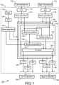
- Fig.1 is a diagram of a first embodiment 100 of a system in the invention.
- the first embodiment 100 comprises a left microphone 102 placed at, or near, the user's left ear (not shown) and a right microphone 104 placed at, or near, the user's right ear (not shown).
- the first embodiment 100 comprises a left loudspeaker 106, placed at, or in, the user's left ear, and a right loudspeaker 108 placed at, or in, the user's right ear. It is assumed in the first embodiment 100 that each of the left microphone 102 and the right microphone 104 is acoustically well isolated from both the left loudspeaker 106 and the right loudspeaker 108.
- the left microphone 102, the right microphone 104, the left loudspeaker 106 and the right loudspeaker 108 form part of a pair of microphone-equipped earphones, such as the Roland CS-10EM, which is commercially available.
- the left loudspeaker 106 fits into the left ear
- the right loudspeaker 108 fits into the right ear
- the left microphone 102 and the right microphone 104 each face outwards relative to the head of the user.
- the left microphone 102 and the right microphone 104 are configured, for all practical purposes, to not pick up the sounds emitted by the left loudspeaker 106 and the right loudspeaker 108, the left microphone 102 and the right microphone 104 are said to be acoustically well isolated from the left loudspeaker 106 and the right loudspeaker 108.
- the first embodiment 100 comprises a signal-processing sub-system 103 between, on the one hand, the left microphone 102 and the right microphone 104 and, on the other hand, the left loudspeaker 106 and the right loudspeaker 108.
- the functionality of the signal-processing sub-system 103 will now be discussed.
- the left microphone 102 captures sounds incident on the left microphone 102 and produces a left audio signal for a left audio channel.
- the left audio signal is converted to the frequency domain in a left converter 110 that produces a left spectrum.
- the right microphone 104 captures sounds incident on the right microphone 104 and produces a right audio signal for a right audio channel.
- the right audio signal is converted to the frequency domain by a right converter 112 that produces a right spectrum. Operation of the left converter 110 and of the right converter 112 is based on, e.g., the Fast-Fourier Transform (FFT).
- FFT Fast-Fourier Transform
- the left spectrum is supplied to a set of one or more left band-pass filters 114 that determines one or more frequency bands in the left spectrum.
- the right spectrum is supplied to a set of one or more right band-pass filters 116 that determines one or more frequency bands in the right spectrum. Dividing each respective one of the left spectrum and the right spectrum into respective frequency bands enables to separately process different bands in the same spectrum.
- the set of left band-pass filters 114 determines one or more frequency bands in the left spectrum, wherein each particular one of the frequency bands is associated with a particular one of the auditory band-pass filters.
- the asymmetric filter shape per individual band-pass filter in a psychoacoustic model of auditory perception is approximated in practice by a symmetric frequency-response function, known as the Rounded Exponential (RoEx) shape.
- the set of right band-pass filters 116 determines one or more frequency bands in the right spectrum, wherein each particular one of the frequency bands is associated with a particular one of the auditory band-pass filters.
- the first embodiment 100 also comprises a masking sound generator 118 that is configured for generating a signal representative of the masking sound.
- the masking sound signal is converted to the frequency domain by a further frequency converter 120 to generate a spectrum of the masking sound.
- the spectrum of the masking sound is supplied to a set of one or more further band-pass filters 122.
- the set of further band-pass filters 122 determines respective frequency bands in the spectrum of the masking sound that correspond with respective ones of the frequency ranges determined by the set of left band-pass filters 114 and the set of right band-pass filters 116.
- a particular part of the left spectrum associated with a particular frequency range, another particular part of the right spectrum associated with this particular frequency range and a further particular part of the spectrum of the masking sound associated with the particular frequency range are supplied to a particular one of a first sub-system 124, a second sub-system 126, a third sub-system 128, etc.
- the processing of the particular part of the left spectrum, of the other particular part of the right spectrum and of the further particular part of the spectrum of the masking sound is explained with reference to the processing by the first sub-system 124.
- the first sub-system 124 comprises a spectrum analyzer 130, a spatial analyzer 134 and a generator sub-system 135.
- the generator sub-system 135 comprises a spectrum equalizer 132 and a virtualizer 136.
- the second sub-system 126, the third sub-system 128, etc. have a configuration similar to that of the first sub-system 124.
- the generator sub-system 135 is configured to generate a masking sound under combined control of a power attribute, as determined by the spectrum analyzer 130, and a directional attribute as determined by the spatial analyzer 134, for masking the sound as captured by the left microphone 102 and the right microphone 104.
- the spectrum analyzer 130 is configured for estimating, or determining, the power in the relevant one of the frequency ranges that is being handled by the first sub-system 124 for the sound captured by the left microphone 102 and the right microphone combined.
- the power in the relevant frequency range as determined by the spectrum analyzer is used to control the spectrum equalizer 132.
- the spectrum equalizer 132 is configured to adjust the power in the relevant frequency range of the masking sound under control of the power estimated by the spectrum analyzer 130 as being present in the relevant frequency range of the incident sound captured by the left microphone 102 and the right microphone 104.
- the spectrum equalizer 132 is adjustable so as to set control parameters in advance for adjusting the power in the relevant frequency range of the masking sound in dependence on the power spectrum of the relevant frequency range of the captured sound.
- the adjustability of the spectrum equalizer enables to limit a ratio between the power in the frequency range of the captured sound and the power in the frequency range of the masking sound to a range between a minimum value and a maximum value. This limiting of the ratio assists in creating a masking sound that will be perceived by the user as more natural rather than artificial.
- the spatial analyzer 134 is configured to determine a directional attribute, e.g., a direction of incidence on the left microphone 102 and on the right microphone 104, of that particular contribution of the sound, which is captured by the left microphone 102 and the right microphone 104 and which is associated with the relevant frequency range.
- a directional attribute e.g., a direction of incidence on the left microphone 102 and on the right microphone 104
- the spatial analyzer 134 thus performs sound localization of the contribution to the captured sound in the relevant frequency range.
- sound localization refers to a person's ability to identify a location of a detected sound in direction and distance. Sound localization may also refer to methods in acoustical engineering to simulate the placement of an auditory cue in a virtual three-dimensional space.
- ITD interaural time difference
- ILD interaural level difference
- the ITD is the difference in arrival times of a sound arriving at the person's left ear and the person's right ear.
- the spatial analyzer 134 is configured, e.g., to determine a quantity representative of at least one of the ITD and ILD for the sound captured by the left microphone 102 and the right microphone 104.
- the virtualizer 136 is configured for generating, under combined control of the spectrum equalizer 130 and the spatial analyzer 134, a left-channel representation and a right-channel representation of a masking sound in the frequency domain and associated with the relevant frequency range.
- the left-channel representation is supplied to a left inverse-converter 138 for being converted to the time-domain, e.g., through an inverse FFT.
- the left-channel representation in the time-domain is then supplied to the left loudspeaker 106.
- the right-channel representation is supplied to a right inverse-converter 140 for being converted to the time-domain, e.g., through an inverse FFT.
- the right-channel representation in the time-domain is then supplied to the right loudspeaker 108.
- Each respective one of the second sub-system 126 and the third sub-system 128, etc. performs similar operations for processing a respective contribution to the captured sound from a respective other frequency range.
- the eventual masking sound as played out at the left loudspeaker 106 and the right loudspeaker 108 then comprises the respective left-channel representation in the time domain and the respective right-channel representation in the time domain as supplied by a respective one of the first sub-system 124, the second sub-system 126, the third sub-system 128 etc.
- the sound captured by the microphones, here: the left microphone 102 and the right microphone 104, may stem from two or more sources or may be incident on the microphones from multiple directions (e.g., through multiple reflections at acoustically reflecting objects within range of the microphones).
- the first embodiment 100 determines the power spectrum and direction of incidence per individual one of the frequency ranges and generates an eventual masking sound taking into account the multiple sources and/or multiple directions of incidence.
- some reverberation may be added so as to strengthen the impression by the user that the masking sound as perceived stems from one or more sources external to the user's head.
- the first embodiment 100 is illustrated as including the left microphone 102 and the right microphone 104. If one or more additional microphones are present in the first embodiment 100, the output signal of each additional microphone is supplied to an additional frequency converter (not shown), and from there to an additional set of band-pass filters (not shown). Each individual one of the band-pass filters of the additional set supplies a particular output signal, indicative of a particular frequency range, to a particular one of the first sub-system 124, the second sub-system 126, the third sub-system 128, etc.
- the specific output signal of the additional set of band-pass filters that is supplied to the first sub-system 124.
- the specific output signal is then supplied to the spectrum analyzer 130 and to the spatial analyzer 134, in parallel to the left output signal of the set of left band-pass filters 114 supplied to the first sub-system 124, and in parallel to the right output signal of the set of right band-pass filters 116 as supplied to the first sub-system 124.
- a typical active noise-cancellation headphone has both a loudspeaker unit and a microphone unit positioned inside each of the ear cups. That is, a typical active noise-cancellation headphone has the left microphone 102 and the left loudspeaker 106 positioned inside the left ear cup, and has the right microphone 104 and the right loudspeaker 108 positioned inside the right ear cup.
- the masking sound reproduced by the left loudspeaker 106 will be picked up by the left microphone 102, and the masking sound reproduced by the right loudspeaker 108 will be picked up by the right microphone 104.
- each individual one of the left microphone 102 and the right microphone 104 is acoustically coupled to both the left loudspeaker 106 and the right loudspeaker 108.
- the removal of the masking sound as captured by each individual one of the left microphone 102 and the right microphone 104 can be implemented through use of adaptive filtering, as is explained with reference to the diagram of Fig.2 .
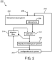
- Fig.2 is a diagram of a second embodiment 200 of a system in the invention.
- the second embodiment 200 comprises a microphone sub-system 202, a loudspeaker sub-system 204 and the signal-processing sub-system 103 as discussed above.
- the microphone sub-system 202 may comprise one, two or more microphones, of which only a specific one is indicated with reference numeral 206.
- the loudspeaker system 204 may comprise one, two or more loudspeakers.
- Each individual one of the microphones of the microphone sub-system 202 may capture the sound to be masked as well as the masking sound, as reproduced by the loudspeaker sub-system 204 in the manner described above with reference to the first embodiment 100.
- the sound to be masked is indicated in the diagram of Fig.2 with a reference numeral 208.
- the masking sound is indicated in the diagram of Fig.2 with a reference numeral 210.
- the adaptive filtering is applied per individual one of the microphones of the microphone sub-system 202 and will be explained with reference to the specific microphone 206.
- the specific microphone 206 captures the sound to be masked 208 as well as the masking sound 210 and supplies a first signal.
- the first signal is supplied to the signal-processing sub-system 103 via a subtractor 212.
- the subtractor 212 also receives a filter output signal from an adaptive filter 214 and is operative to subtract the filter output signal from the microphone signal.
- the output signal of the subtractor 212 is supplied to the signal- processing sub-system 103 described with reference to the first embodiment 100.
- the output signal of the signal-processing sub-system 103 as supplied to the loudspeaker sub-system 204 is supplied to an input of the adaptive filter 214.
- the adaptive filter 214 is configured for adjusting its filter coefficients under control of the output signal of the subtractor 212. Adaptive filtering techniques are well-known in the art and need not be discussed here in further detail.
- the wearing of headphones may be inconvenient.
- the loudspeakers and microphones of a system of the invention are positioned at a distance from the head of the user.
- an array of two or more microphones can used to obtain the directions of the disturbing sounds to be masked with respect to a preferably fixed position of the user's head using a beamforming technique.
- the possible positions of the head of a patient lying in a hospital bed, erected at a fixed location in a hospital room is usually limited to a small volume of space.
- a one-dimensional array of microphones can then be used to sweep (in software) a narrow (microphone-) beam pattern along an axis that has a particular orientation with respect to the patient, e.g., the horizontal axis.
- a two-dimensional array of microphones can then be used to sweep (in software) a narrow (microphone-) beam pattern along two axes that have different particular orientations with respect to the patient, e.g., the horizontal axis and the vertical axis.
- an implementation of the spatial analyzer 134 may be used for determining the ITD and ILD. If the microphones are positioned remote form the user's head and if beamforming is being used to determine the directions of the sounds to be masked, another implementation of the spatial analyzer 134 may be used that is adapted to the specific beamforming technique.
- an implementation of the virtualizer 136 may be used so that, given the estimated incident directions of the target sounds, the masking sounds may be rendered at the same directions using the loudspeaker sub-system.
- This can be achieved by filtering the binaural signals with a matrix of filters to synthesize input signals for the loudspeaker array, where the filters are created so that the transmission paths to the user's ear positions may be relatively transparent (e.g., using cross-talk cancellation).
- beamforming can be used wherein two narrow beams are formed by a filter matrix, each respective one of which being directed to the respective one of the position of the user's left ear and the position of the user's right ear.
- Cross-talk cancellation is known in the art.
- the objective of a cross-talk canceller is to reproduce a desired signal at a single target position while cancelling out the sound perfectly at all remaining target positions.
- the basic principle of cross-talk cancellation using only two loudspeakers and two target positions has been known for a long time.
- Atal and Schroeder used physical reasoning to determine how a cross-talk canceller comprising only two loudspeakers placed symmetrically in front of a single listener could work.
- the left loudspeaker In order to reproduce a short pulse at the left ear only, the left loudspeaker first emits a positive pulse. This pulse must be cancelled at the right ear by a slightly weaker negative pulse emitted by the right loudspeaker.
- the location(s), where the masking sound is intended to effectively mask the sound to be masked can be fixed regardless of the direction(s) from the sound(s) to be masked is/are arriving at the user's head.
- the sources of sounds to be masked e.g., electronic monitoring systems
- the sources of sounds to be masked are mostly located to the side of, or behind, the patient's bed.
- masking sounds can be created that have fixed directionality and only to the lateral positions and to the back, reducing the variability of the soundscape, and also reducing the required computational power needed for the adaptive filtering (as some of the adaptive filters can use fixed filter coefficients).
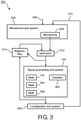
- Fig.3 is a third embodiment 300 of a system in the invention.
- the third embodiment 300 comprises a sound classifier 302.
- the sound classifier 302 determines which portion of the sound as captured by the microphone sub-system 202 is going to be excluded from being masked. That is, the sound classifier 302 is configured to discriminate between sounds, captured by the microphone sub-system 202 and which are to be masked, and other sounds, which are captured by the microphone sub-system 202 and which are not to be masked (e.g., a human voice or an alarm), so as to selectively subject captured sounds to the process of being masked.
- sounds e.g., a human voice or an alarm
- the sound classifier 302 then blocks this portion of the captured sound from contributing to the generation of the masking sound.
- the sound classifier 302 may be implemented by selectively adjusting or programming in advance the band-pass filters, e.g., the left set of band-pass filters 114 and the right set of band-pass filters 116, whose output signals are supplied to the spectrum analyzer and spatial analyzer in each of the first sub-system 124, the second sub-system 126, the third sub-system 128, etc., so as to exclude certain frequency ranges in the captured sound from contributing to the eventual masking sound.
- the sound classifier 302 may be implemented by selectively inactivating the signal-processing sub-system 103 in the presence of a pre-determined type of contribution to the capture sound, the contribution being indicative of a sound that is not to be masked.
- the inactivating may be implemented under control of an additional spectrum-analyzer (not shown) that inactivates the signal-processing system 103 upon detecting a particular pattern in the frequency spectrum of the captured sound, or that inactivates the supply of the microphone signal to the subtractor 212 or to the signal processing sub-system 103 upon detecting a particular pattern in the frequency spectrum of the captured sound.
- the first embodiment 100 is shown to accommodate the masking sound generator 118.
- the third embodiment 300 comprises one or more additional masking sound generators, e.g., a first additional masking sound generator 306 and a second additional masking sound generator 308, etc. Accordingly, instead of using a single type of masking sound for the processing at the signal-processing sub-system 103, a multitude of different masking sounds is used, a particular one of the masking sounds being tuned to a particular one of the sources that together produce the sound to be masked.
Landscapes
- Engineering & Computer Science (AREA)
- Computer Networks & Wireless Communication (AREA)
- Signal Processing (AREA)
- Physics & Mathematics (AREA)
- Acoustics & Sound (AREA)
- Multimedia (AREA)
- Health & Medical Sciences (AREA)
- Audiology, Speech & Language Pathology (AREA)
- General Health & Medical Sciences (AREA)
- Soundproofing, Sound Blocking, And Sound Damping (AREA)
- Circuit For Audible Band Transducer (AREA)
- Measurement Of Mechanical Vibrations Or Ultrasonic Waves (AREA)
- Obtaining Desirable Characteristics In Audible-Bandwidth Transducers (AREA)
- Stereophonic System (AREA)
Claims (8)
- Signalverarbeitungs-Untersystem (103), das angepasst ist, um zwischen einem Mikrofon-Untersystem (102, 104; 202) zum gleichzeitigen Erfassen eines Geräusches an mehreren Orten und einem Lautsprecher-Untersystem (106, 108; 204) zum Erzeugen eines Maskierungsgeräusches unter Steuerung des erfassten Geräusches eines Systems (100; 200) gekoppelt zu werden, das zum Maskieren eines auf eine Person einfallenden Geräusches konfiguriert ist, wobei das Signalverarbeitungs-Untersystem konfiguriert ist zum:Bestimmen eines Leistungsattributs eines Frequenzspektrums des erfassten Geräusches, das für eine Leistung in einem Frequenzband des erfassten Geräusches repräsentativ ist;Bestimmen eines Richtungsattributs des erfassten Geräusches in dem Frequenzband, das für eine Richtung repräsentativ ist, aus der das Geräusch auf die Person einfällt; undSteuern des Lautsprecher-Untersystems, um den Maskierungsgeräusch unter kombinierter Steuerung des Leistungsattributs und des Richtungsattributs zu erzeugen,
und wobei das Signalverarbeitungs-Untersystem einen räumlichen Analysator (134) zum Bestimmen des Richtungsattributs umfasst;dadurch gekennzeichnet, dassdie mehreren Orte einen ersten Ort am oder in der Nähe des linken Ohrs des Benutzers und einen zweiten Ort am oder in der Nähe des rechten Ohrs des Benutzers umfassen, undder räumliche Analysator (134) wirksam ist, um das Richtungsattribut basierend auf der Bestimmung einer Größe zu bestimmen, die repräsentativ ist für mindestens eines von: einer interauralen Zeitdifferenz und einer interauralen Pegeldifferenz. - System (100; 200), das zum Maskieren eines auf eine Person einfallenden Geräusches konfiguriert ist, wobei das System umfasst:das Signalverarbeitungs-Untersystem (103) nach Anspruch 1;das Mikrofon-Untersystem (102, 104; 202);das Lautsprecher-Untersystem (106, 108; 204); und wobeidas Signalverarbeitungs-Untersystem (103) nach Anspruch 1 zwischen das Mikrofon-Untersystem und das Lautsprecher-Untersystem gekoppelt ist.
- System nach Anspruch 2, wobei:das Mikrofon-Untersystem (102, 104; 202) ein erstes Signal liefert, das für den erfassten Geräusch repräsentativ ist;das Signalverarbeitungs-Untersystem (103) ein zweites Signal zur Steuerung des Lautsprecher-Untersystems liefert;das System ein adaptives Filteruntersystem (212; 214) umfasst, das betriebsfähig ist, um einen Beitrag des Maskierungsgeräusches, der in dem erfassten Geräusch vorhanden ist, zu dem zweiten Signal zu reduzieren;das adaptive Filtersystem ein adaptives Filter (214) und einen Subtrahierer (212) umfasst;der adaptive Filter einen Filtereingang zum Empfangen des zweiten Signals und einen Filterausgang zum Liefern einer gefilterten Version des zweiten Signals aufweist;der Subtrahierer einen ersten Subtrahierereingang zum Empfangen des ersten Signals, einen zweiten Subtrahierereingang zum Empfangen der gefilterten Version des zweiten Signals und einen Subtrahiererausgang zum Liefern eines dritten Signals an das Signalverarbeitungs-Untersystem aufweist, das für eine Differenz zwischen dem ersten Signal und der gefilterten Version des zweiten Signals repräsentativ ist; unddas adaptive Filter einen Steuereingang zum Empfangen des dritten Signals zur Steuerung eines oder mehrerer Filterkoeffizienten des adaptiven Filters aufweist.
- System nach Anspruch 2, das einen Geräuschklassifizierer (302) umfasst, der wirksam ist, um selektiv einen vorbestimmten Abschnitt aus dem erfassten Geräusch zu entfernen, bevor das Bestimmen des Leistungsattributs und vor dem Ausführen des Bestimmens des Richtungsattributs ausgeführt wird.
- Verfahren zum Maskieren eines auf eine Person einfallenden Geräusches, wobei:das Verfahren umfasst:gleichzeitiges Erfassen des Geräusches an mehreren Orten;Bestimmen eines Leistungsattributs eines Frequenzspektrums des erfassten Geräusches, das für eine Leistung in einem Frequenzband des erfassten Geräusches repräsentativ ist;Bestimmen eines Richtungsattributs des erfassten Geräusches in dem Frequenzband, das für eine Richtung repräsentativ ist, aus der das Geräusch auf die Person einfällt; undErzeugen eines Maskierungsgeräusches unter kombinierter Kontrolle des Leistungsattributs und des Richtungsattributs,dadurch gekennzeichnet, dassdie mehreren Orte einen ersten Ort am oder in der Nähe des linken Ohrs des Benutzers und einen zweiten Ort am oder in der Nähe des rechten Ohrs des Benutzers umfassen; unddas Verfahren das Bestimmen einer Größe umfasst, die repräsentativ ist für mindestens eines von: einer interauralen Zeitdifferenz und einer interauralen Pegeldifferenz.
- Verfahren nach Anspruch 5, wobei:das Verfahren umfasst:Empfangen eines ersten Signals, das für den erfassten Geräusch repräsentativ ist;Liefern eines zweiten Signals zum Erzeugen des Maskierungsgeräusches; undadaptives Filtern zum Reduzieren eines Beitrags des Maskierungsgeräusches, der in dem erfassten Geräusch vorhanden ist, zu dem zweiten Signal;die adaptive Filterung umfasst:Empfangen des zweiten Signals;Verwenden eines adaptiven Filters zum Liefern einer gefilterten Version des zweiten Signals;Liefern eines dritten Signals, das für eine Differenz zwischen dem ersten Signal und der gefilterten Version des zweiten Signals repräsentativ ist;Empfangen des dritten Signals zur Steuerung eines oder mehrerer Filterkoeffizienten des adaptiven Filters; undVerwenden des dritten Signals zum Bestimmen des Leistungsattributs und zum Bestimmen des Richtungsattributs.
- Verfahren nach Anspruch 5, umfassend das selektive Entfernen eines vorbestimmten Abschnitts aus dem erfassten Geräusch, vor dem Bestimmen des Leistungsattributs und vor dem Ausführen des Bestimmens des Richtungsattributs ausgeführt wird.
- Computerprogramm, das Anweisungen umfasst, um das System nach Anspruch 2 zu veranlassen, die Schritte des Verfahrens nach einem der Ansprüche 5 bis 7 auszuführen.
Applications Claiming Priority (2)
| Application Number | Priority Date | Filing Date | Title |
|---|---|---|---|
| US201261674920P | 2012-07-24 | 2012-07-24 | |
| PCT/IB2013/055726 WO2014016723A2 (en) | 2012-07-24 | 2013-07-12 | Directional sound masking |
Publications (2)
| Publication Number | Publication Date |
|---|---|
| EP2877991A2 EP2877991A2 (de) | 2015-06-03 |
| EP2877991B1 true EP2877991B1 (de) | 2022-02-23 |
Family
ID=49237551
Family Applications (1)
| Application Number | Title | Priority Date | Filing Date |
|---|---|---|---|
| EP13766697.0A Active EP2877991B1 (de) | 2012-07-24 | 2013-07-12 | Direktionale geräuschmaskierung |
Country Status (7)
| Country | Link |
|---|---|
| US (1) | US9613610B2 (de) |
| EP (1) | EP2877991B1 (de) |
| JP (1) | JP6279570B2 (de) |
| CN (1) | CN104508738B (de) |
| BR (1) | BR112015001297A2 (de) |
| RU (1) | RU2647213C2 (de) |
| WO (1) | WO2014016723A2 (de) |
Families Citing this family (27)
| Publication number | Priority date | Publication date | Assignee | Title |
|---|---|---|---|---|
| ITTO20130376A1 (it) * | 2013-05-10 | 2014-11-11 | Recwon S R L | Metodo per la registrazione di una pluralità di file audio |
| JP6098654B2 (ja) * | 2014-03-10 | 2017-03-22 | ヤマハ株式会社 | マスキング音データ生成装置およびプログラム |
| DE102014214052A1 (de) * | 2014-07-18 | 2016-01-21 | Bayerische Motoren Werke Aktiengesellschaft | Virtuelle Verdeckungsmethoden |
| EP3040984B1 (de) * | 2015-01-02 | 2022-07-13 | Harman Becker Automotive Systems GmbH | Schallzonenanordnung mit zonenweiser sprachunterdrückung |
| US9558731B2 (en) * | 2015-06-15 | 2017-01-31 | Blackberry Limited | Headphones using multiplexed microphone signals to enable active noise cancellation |
| DK3108929T3 (da) * | 2015-06-22 | 2020-08-31 | Oticon Medical As | Lydbehandling til et bilateralt cochleaimplantatsystem |
| DE102015122194A1 (de) | 2015-12-18 | 2017-06-22 | Robert Bosch Automotive Steering Gmbh | Verfahren zur Maskierung und/oder zur Reduzierung störender Geräusche oder deren Auffälligkeit bei dem Betrieb eines Kraftfahrzeugs |
| CN105679300A (zh) * | 2015-12-29 | 2016-06-15 | 努比亚技术有限公司 | 移动终端和降噪方法 |
| KR102606286B1 (ko) | 2016-01-07 | 2023-11-24 | 삼성전자주식회사 | 전자 장치 및 전자 장치를 이용한 소음 제어 방법 |
| JP6629625B2 (ja) * | 2016-02-19 | 2020-01-15 | 学校法人 中央大学 | 作業環境改善システム |
| WO2017201269A1 (en) | 2016-05-20 | 2017-11-23 | Cambridge Sound Management, Inc. | Self-powered loudspeaker for sound masking |
| TR201615941A1 (tr) | 2016-11-08 | 2018-05-21 | Arcelik As | Bi̇r ses maskeleme yöntemi̇ ve kullanildiği ses maskeleme ci̇hazi |
| TR201701638A2 (tr) | 2017-02-03 | 2018-08-27 | Arcelik As | Bi̇r ses kaynaği i̇çeren bi̇r ev ci̇hazi |
| US10224017B2 (en) * | 2017-04-26 | 2019-03-05 | Ford Global Technologies, Llc | Active sound desensitization to tonal noise in a vehicle |
| JP7013789B2 (ja) * | 2017-10-23 | 2022-02-01 | 富士通株式会社 | 音声処理用コンピュータプログラム、音声処理装置及び音声処理方法 |
| US11902758B2 (en) | 2018-12-21 | 2024-02-13 | Gn Audio A/S | Method of compensating a processed audio signal |
| US10638248B1 (en) * | 2019-01-29 | 2020-04-28 | Facebook Technologies, Llc | Generating a modified audio experience for an audio system |
| US11071843B2 (en) | 2019-02-18 | 2021-07-27 | Bose Corporation | Dynamic masking depending on source of snoring |
| US10991355B2 (en) | 2019-02-18 | 2021-04-27 | Bose Corporation | Dynamic sound masking based on monitoring biosignals and environmental noises |
| US11282492B2 (en) * | 2019-02-18 | 2022-03-22 | Bose Corporation | Smart-safe masking and alerting system |
| EP3800900A1 (de) * | 2019-10-04 | 2021-04-07 | GN Audio A/S | Am körper tragbare elektronische vorrichtung zum aussenden eines maskierungssignals |
| EP3840404B8 (de) * | 2019-12-19 | 2023-11-01 | Steelseries France | Verfahren zur audiowiedergabe durch eine vorrichtung |
| US11217220B1 (en) * | 2020-10-03 | 2022-01-04 | Lenovo (Singapore) Pte. Ltd. | Controlling devices to mask sound in areas proximate to the devices |
| EP4167228A1 (de) * | 2021-10-18 | 2023-04-19 | Audio Mobil Elektronik GmbH | Audio-maskierung von sprechern |
| WO2023066908A1 (de) * | 2021-10-18 | 2023-04-27 | Audio Mobil Elektronik Gmbh | Audio-maskierung von sprache |
| CN114120950B (zh) * | 2022-01-27 | 2022-06-10 | 荣耀终端有限公司 | 一种人声屏蔽方法和电子设备 |
| EP4365890A1 (de) | 2022-11-07 | 2024-05-08 | Fraunhofer-Gesellschaft zur Förderung der angewandten Forschung e.V. | Vorrichtung und verfahren zur adaptiven, harmonischen sprachmaskierschallerzeugung |
Family Cites Families (17)
| Publication number | Priority date | Publication date | Assignee | Title |
|---|---|---|---|---|
| US20050254663A1 (en) * | 1999-11-16 | 2005-11-17 | Andreas Raptopoulos | Electronic sound screening system and method of accoustically impoving the environment |
| JP2005258158A (ja) * | 2004-03-12 | 2005-09-22 | Advanced Telecommunication Research Institute International | ノイズ除去装置 |
| RU41944U1 (ru) * | 2004-06-29 | 2004-11-10 | Общество с ограниченной ответственностью "Центр безопасности информации "МАСКОМ" | Система защиты помещения от несанкционированного перехвата акустической речевой информации (варианты) |
| US7376557B2 (en) * | 2005-01-10 | 2008-05-20 | Herman Miller, Inc. | Method and apparatus of overlapping and summing speech for an output that disrupts speech |
| US20070050933A1 (en) | 2005-09-02 | 2007-03-08 | Brezler Russel A | Variable diameter filaments |
| EP1770685A1 (de) * | 2005-10-03 | 2007-04-04 | Maysound ApS | System zur Verminderung der hörbaren Wahrnehmung des Schallstörpegels eines Menschen. |
| US8229130B2 (en) * | 2006-10-17 | 2012-07-24 | Massachusetts Institute Of Technology | Distributed acoustic conversation shielding system |
| KR100969138B1 (ko) * | 2008-05-06 | 2010-07-08 | 광주과학기술원 | 은닉 마코프 모델을 이용한 잡음 마스크 추정 방법 및 이를수행하는 장치 |
| JP5271734B2 (ja) * | 2009-01-30 | 2013-08-21 | セコム株式会社 | 話者方向推定装置 |
| JP2010217268A (ja) * | 2009-03-13 | 2010-09-30 | Akita Prefectural Univ | 音源方向知覚が可能な両耳信号を生成する低遅延信号処理装置 |
| DK2485644T3 (en) | 2009-10-09 | 2016-12-05 | Auckland Uniservices Ltd | Tinnitus treatment system and method |
| JP2012032648A (ja) * | 2010-07-30 | 2012-02-16 | Sony Corp | 機械音抑圧装置、機械音抑圧方法、プログラムおよび撮像装置 |
| JP5849411B2 (ja) * | 2010-09-28 | 2016-01-27 | ヤマハ株式会社 | マスカ音出力装置 |
| JP2012093705A (ja) * | 2010-09-28 | 2012-05-17 | Yamaha Corp | 音声出力装置 |
| JP5707871B2 (ja) * | 2010-11-05 | 2015-04-30 | ヤマハ株式会社 | 音声通話装置及び携帯電話 |
| US8972251B2 (en) * | 2011-06-07 | 2015-03-03 | Qualcomm Incorporated | Generating a masking signal on an electronic device |
| CN102543066B (zh) * | 2011-11-18 | 2014-04-02 | 中国科学院声学研究所 | 一种目标语音的隐私保护方法及其系统 |
-
2013
- 2013-07-12 BR BR112015001297A patent/BR112015001297A2/pt not_active Application Discontinuation
- 2013-07-12 CN CN201380039413.4A patent/CN104508738B/zh not_active Expired - Fee Related
- 2013-07-12 RU RU2015105771A patent/RU2647213C2/ru not_active IP Right Cessation
- 2013-07-12 WO PCT/IB2013/055726 patent/WO2014016723A2/en active Application Filing
- 2013-07-12 EP EP13766697.0A patent/EP2877991B1/de active Active
- 2013-07-12 US US14/414,528 patent/US9613610B2/en active Active
- 2013-07-12 JP JP2015523632A patent/JP6279570B2/ja not_active Expired - Fee Related
Also Published As
| Publication number | Publication date |
|---|---|
| US20150194144A1 (en) | 2015-07-09 |
| CN104508738B (zh) | 2017-12-08 |
| RU2015105771A (ru) | 2016-09-10 |
| JP2015526761A (ja) | 2015-09-10 |
| WO2014016723A2 (en) | 2014-01-30 |
| EP2877991A2 (de) | 2015-06-03 |
| CN104508738A (zh) | 2015-04-08 |
| WO2014016723A3 (en) | 2014-07-17 |
| RU2647213C2 (ru) | 2018-03-14 |
| US9613610B2 (en) | 2017-04-04 |
| JP6279570B2 (ja) | 2018-02-14 |
| BR112015001297A2 (pt) | 2017-07-04 |
Similar Documents
| Publication | Publication Date | Title |
|---|---|---|
| EP2877991B1 (de) | Direktionale geräuschmaskierung | |
| EP3013070B1 (de) | Hörgerätesystem | |
| Arweiler et al. | The influence of spectral characteristics of early reflections on speech intelligibility | |
| EP2088802B1 (de) | Verfahren zur Schätzung der Gewichtungsfunktion von Audiosignalen in einem Hörgerät | |
| EP2882203A1 (de) | Hörgerätevorrichtung für freihändige Kommunikation | |
| US20130094657A1 (en) | Method and device for improving the audibility, localization and intelligibility of sounds, and comfort of communication devices worn on or in the ear | |
| DK2835986T3 (en) | Hearing aid with input transducer and wireless receiver | |
| Mueller et al. | Localization of virtual sound sources with bilateral hearing aids in realistic acoustical scenes | |
| Corey et al. | Acoustic impulse responses for wearable audio devices | |
| US10469962B2 (en) | Systems and methods for facilitating interaural level difference perception by enhancing the interaural level difference | |
| JP2016140059A (ja) | 外部からピックアップされたマイクロホン信号の上に空間聴覚キューを重ね合わせる方法 | |
| JP2019041382A (ja) | 音響デバイス | |
| WO2005004534A1 (en) | The production of augmented-reality audio | |
| Joubaud et al. | Sound localization models as evaluation tools for tactical communication and protective systems | |
| EP3148217B1 (de) | Verfahren zum betrieb eines binauralen hörsystems | |
| Brammer et al. | Understanding speech when wearing communication headsets and hearing protectors with subband processing | |
| CN110620982A (zh) | 用于助听器中的音频播放的方法 | |
| Usagawa | Application of active control technique on a bone conduction headphone for estimating a cross-talk compensation filter | |
| US20230143325A1 (en) | Hearing device or system comprising a noise control system | |
| Farmani | Informed Sound Source Localization for Hearing Aid Applications | |
| Maillou et al. | Measuring the Performance of the Hearing Aids Adaptive Directivity and Noise Reduction Algorithms through SNR Values | |
| Avendano | Virtual spatial sound | |
| Chapin et al. | Concept and Technology Exploration for Transparent Hearing Project Final Report | |
| Ortolani | Binaural approach in acoustic scene simulations in audio forensics | |
| Müller | Measuring, predicting and improving the perception of space with bilateral hearing instruments |
Legal Events
| Date | Code | Title | Description |
|---|---|---|---|
| PUAI | Public reference made under article 153(3) epc to a published international application that has entered the european phase |
Free format text: ORIGINAL CODE: 0009012 |
|
| 17P | Request for examination filed |
Effective date: 20150224 |
|
| AK | Designated contracting states |
Kind code of ref document: A2 Designated state(s): AL AT BE BG CH CY CZ DE DK EE ES FI FR GB GR HR HU IE IS IT LI LT LU LV MC MK MT NL NO PL PT RO RS SE SI SK SM TR |
|
| AX | Request for extension of the european patent |
Extension state: BA ME |
|
| DAX | Request for extension of the european patent (deleted) | ||
| STAA | Information on the status of an ep patent application or granted ep patent |
Free format text: STATUS: EXAMINATION IS IN PROGRESS |
|
| 17Q | First examination report despatched |
Effective date: 20190215 |
|
| STAA | Information on the status of an ep patent application or granted ep patent |
Free format text: STATUS: EXAMINATION IS IN PROGRESS |
|
| RAP1 | Party data changed (applicant data changed or rights of an application transferred) |
Owner name: KONINKLIJKE PHILIPS N.V. |
|
| GRAP | Despatch of communication of intention to grant a patent |
Free format text: ORIGINAL CODE: EPIDOSNIGR1 |
|
| STAA | Information on the status of an ep patent application or granted ep patent |
Free format text: STATUS: GRANT OF PATENT IS INTENDED |
|
| RIC1 | Information provided on ipc code assigned before grant |
Ipc: H04K 3/00 20060101ALI20210830BHEP Ipc: G10K 11/175 20060101AFI20210830BHEP |
|
| INTG | Intention to grant announced |
Effective date: 20210923 |
|
| RIN1 | Information on inventor provided before grant (corrected) |
Inventor name: VAN LEEST, ARNO Inventor name: KOHLRAUSCH, ARMIN GERHARD Inventor name: PARK, MUN HUM |
|
| GRAS | Grant fee paid |
Free format text: ORIGINAL CODE: EPIDOSNIGR3 |
|
| GRAA | (expected) grant |
Free format text: ORIGINAL CODE: 0009210 |
|
| STAA | Information on the status of an ep patent application or granted ep patent |
Free format text: STATUS: THE PATENT HAS BEEN GRANTED |
|
| AK | Designated contracting states |
Kind code of ref document: B1 Designated state(s): AL AT BE BG CH CY CZ DE DK EE ES FI FR GB GR HR HU IE IS IT LI LT LU LV MC MK MT NL NO PL PT RO RS SE SI SK SM TR |
|
| REG | Reference to a national code |
Ref country code: GB Ref legal event code: FG4D |
|
| REG | Reference to a national code |
Ref country code: CH Ref legal event code: EP |
|
| REG | Reference to a national code |
Ref country code: AT Ref legal event code: REF Ref document number: 1471064 Country of ref document: AT Kind code of ref document: T Effective date: 20220315 |
|
| REG | Reference to a national code |
Ref country code: IE Ref legal event code: FG4D |
|
| REG | Reference to a national code |
Ref country code: DE Ref legal event code: R096 Ref document number: 602013080971 Country of ref document: DE |
|
| REG | Reference to a national code |
Ref country code: LT Ref legal event code: MG9D |
|
| REG | Reference to a national code |
Ref country code: NL Ref legal event code: MP Effective date: 20220223 |
|
| REG | Reference to a national code |
Ref country code: AT Ref legal event code: MK05 Ref document number: 1471064 Country of ref document: AT Kind code of ref document: T Effective date: 20220223 |
|
| PG25 | Lapsed in a contracting state [announced via postgrant information from national office to epo] |
Ref country code: SE Free format text: LAPSE BECAUSE OF FAILURE TO SUBMIT A TRANSLATION OF THE DESCRIPTION OR TO PAY THE FEE WITHIN THE PRESCRIBED TIME-LIMIT Effective date: 20220223 Ref country code: RS Free format text: LAPSE BECAUSE OF FAILURE TO SUBMIT A TRANSLATION OF THE DESCRIPTION OR TO PAY THE FEE WITHIN THE PRESCRIBED TIME-LIMIT Effective date: 20220223 Ref country code: PT Free format text: LAPSE BECAUSE OF FAILURE TO SUBMIT A TRANSLATION OF THE DESCRIPTION OR TO PAY THE FEE WITHIN THE PRESCRIBED TIME-LIMIT Effective date: 20220623 Ref country code: NO Free format text: LAPSE BECAUSE OF FAILURE TO SUBMIT A TRANSLATION OF THE DESCRIPTION OR TO PAY THE FEE WITHIN THE PRESCRIBED TIME-LIMIT Effective date: 20220523 Ref country code: NL Free format text: LAPSE BECAUSE OF FAILURE TO SUBMIT A TRANSLATION OF THE DESCRIPTION OR TO PAY THE FEE WITHIN THE PRESCRIBED TIME-LIMIT Effective date: 20220223 Ref country code: LT Free format text: LAPSE BECAUSE OF FAILURE TO SUBMIT A TRANSLATION OF THE DESCRIPTION OR TO PAY THE FEE WITHIN THE PRESCRIBED TIME-LIMIT Effective date: 20220223 Ref country code: HR Free format text: LAPSE BECAUSE OF FAILURE TO SUBMIT A TRANSLATION OF THE DESCRIPTION OR TO PAY THE FEE WITHIN THE PRESCRIBED TIME-LIMIT Effective date: 20220223 Ref country code: ES Free format text: LAPSE BECAUSE OF FAILURE TO SUBMIT A TRANSLATION OF THE DESCRIPTION OR TO PAY THE FEE WITHIN THE PRESCRIBED TIME-LIMIT Effective date: 20220223 Ref country code: BG Free format text: LAPSE BECAUSE OF FAILURE TO SUBMIT A TRANSLATION OF THE DESCRIPTION OR TO PAY THE FEE WITHIN THE PRESCRIBED TIME-LIMIT Effective date: 20220523 |
|
| PG25 | Lapsed in a contracting state [announced via postgrant information from national office to epo] |
Ref country code: PL Free format text: LAPSE BECAUSE OF FAILURE TO SUBMIT A TRANSLATION OF THE DESCRIPTION OR TO PAY THE FEE WITHIN THE PRESCRIBED TIME-LIMIT Effective date: 20220223 Ref country code: LV Free format text: LAPSE BECAUSE OF FAILURE TO SUBMIT A TRANSLATION OF THE DESCRIPTION OR TO PAY THE FEE WITHIN THE PRESCRIBED TIME-LIMIT Effective date: 20220223 Ref country code: GR Free format text: LAPSE BECAUSE OF FAILURE TO SUBMIT A TRANSLATION OF THE DESCRIPTION OR TO PAY THE FEE WITHIN THE PRESCRIBED TIME-LIMIT Effective date: 20220524 Ref country code: FI Free format text: LAPSE BECAUSE OF FAILURE TO SUBMIT A TRANSLATION OF THE DESCRIPTION OR TO PAY THE FEE WITHIN THE PRESCRIBED TIME-LIMIT Effective date: 20220223 Ref country code: AT Free format text: LAPSE BECAUSE OF FAILURE TO SUBMIT A TRANSLATION OF THE DESCRIPTION OR TO PAY THE FEE WITHIN THE PRESCRIBED TIME-LIMIT Effective date: 20220223 |
|
| PG25 | Lapsed in a contracting state [announced via postgrant information from national office to epo] |
Ref country code: IS Free format text: LAPSE BECAUSE OF FAILURE TO SUBMIT A TRANSLATION OF THE DESCRIPTION OR TO PAY THE FEE WITHIN THE PRESCRIBED TIME-LIMIT Effective date: 20220623 |
|
| PG25 | Lapsed in a contracting state [announced via postgrant information from national office to epo] |
Ref country code: SM Free format text: LAPSE BECAUSE OF FAILURE TO SUBMIT A TRANSLATION OF THE DESCRIPTION OR TO PAY THE FEE WITHIN THE PRESCRIBED TIME-LIMIT Effective date: 20220223 Ref country code: SK Free format text: LAPSE BECAUSE OF FAILURE TO SUBMIT A TRANSLATION OF THE DESCRIPTION OR TO PAY THE FEE WITHIN THE PRESCRIBED TIME-LIMIT Effective date: 20220223 Ref country code: RO Free format text: LAPSE BECAUSE OF FAILURE TO SUBMIT A TRANSLATION OF THE DESCRIPTION OR TO PAY THE FEE WITHIN THE PRESCRIBED TIME-LIMIT Effective date: 20220223 Ref country code: EE Free format text: LAPSE BECAUSE OF FAILURE TO SUBMIT A TRANSLATION OF THE DESCRIPTION OR TO PAY THE FEE WITHIN THE PRESCRIBED TIME-LIMIT Effective date: 20220223 Ref country code: DK Free format text: LAPSE BECAUSE OF FAILURE TO SUBMIT A TRANSLATION OF THE DESCRIPTION OR TO PAY THE FEE WITHIN THE PRESCRIBED TIME-LIMIT Effective date: 20220223 Ref country code: CZ Free format text: LAPSE BECAUSE OF FAILURE TO SUBMIT A TRANSLATION OF THE DESCRIPTION OR TO PAY THE FEE WITHIN THE PRESCRIBED TIME-LIMIT Effective date: 20220223 |
|
| REG | Reference to a national code |
Ref country code: DE Ref legal event code: R097 Ref document number: 602013080971 Country of ref document: DE |
|
| PG25 | Lapsed in a contracting state [announced via postgrant information from national office to epo] |
Ref country code: AL Free format text: LAPSE BECAUSE OF FAILURE TO SUBMIT A TRANSLATION OF THE DESCRIPTION OR TO PAY THE FEE WITHIN THE PRESCRIBED TIME-LIMIT Effective date: 20220223 |
|
| PLBE | No opposition filed within time limit |
Free format text: ORIGINAL CODE: 0009261 |
|
| STAA | Information on the status of an ep patent application or granted ep patent |
Free format text: STATUS: NO OPPOSITION FILED WITHIN TIME LIMIT |
|
| 26N | No opposition filed |
Effective date: 20221124 |
|
| REG | Reference to a national code |
Ref country code: DE Ref legal event code: R119 Ref document number: 602013080971 Country of ref document: DE |
|
| PG25 | Lapsed in a contracting state [announced via postgrant information from national office to epo] |
Ref country code: SI Free format text: LAPSE BECAUSE OF FAILURE TO SUBMIT A TRANSLATION OF THE DESCRIPTION OR TO PAY THE FEE WITHIN THE PRESCRIBED TIME-LIMIT Effective date: 20220223 Ref country code: MC Free format text: LAPSE BECAUSE OF FAILURE TO SUBMIT A TRANSLATION OF THE DESCRIPTION OR TO PAY THE FEE WITHIN THE PRESCRIBED TIME-LIMIT Effective date: 20220223 |
|
| REG | Reference to a national code |
Ref country code: CH Ref legal event code: PL |
|
| GBPC | Gb: european patent ceased through non-payment of renewal fee |
Effective date: 20220712 |
|
| REG | Reference to a national code |
Ref country code: BE Ref legal event code: MM Effective date: 20220731 |
|
| PG25 | Lapsed in a contracting state [announced via postgrant information from national office to epo] |
Ref country code: LU Free format text: LAPSE BECAUSE OF NON-PAYMENT OF DUE FEES Effective date: 20220712 Ref country code: LI Free format text: LAPSE BECAUSE OF NON-PAYMENT OF DUE FEES Effective date: 20220731 Ref country code: FR Free format text: LAPSE BECAUSE OF NON-PAYMENT OF DUE FEES Effective date: 20220731 Ref country code: CH Free format text: LAPSE BECAUSE OF NON-PAYMENT OF DUE FEES Effective date: 20220731 |
|
| PG25 | Lapsed in a contracting state [announced via postgrant information from national office to epo] |
Ref country code: GB Free format text: LAPSE BECAUSE OF NON-PAYMENT OF DUE FEES Effective date: 20220712 Ref country code: DE Free format text: LAPSE BECAUSE OF NON-PAYMENT OF DUE FEES Effective date: 20230201 Ref country code: BE Free format text: LAPSE BECAUSE OF NON-PAYMENT OF DUE FEES Effective date: 20220731 |
|
| PG25 | Lapsed in a contracting state [announced via postgrant information from national office to epo] |
Ref country code: IT Free format text: LAPSE BECAUSE OF FAILURE TO SUBMIT A TRANSLATION OF THE DESCRIPTION OR TO PAY THE FEE WITHIN THE PRESCRIBED TIME-LIMIT Effective date: 20220223 Ref country code: IE Free format text: LAPSE BECAUSE OF NON-PAYMENT OF DUE FEES Effective date: 20220712 |
|
| PG25 | Lapsed in a contracting state [announced via postgrant information from national office to epo] |
Ref country code: HU Free format text: LAPSE BECAUSE OF FAILURE TO SUBMIT A TRANSLATION OF THE DESCRIPTION OR TO PAY THE FEE WITHIN THE PRESCRIBED TIME-LIMIT; INVALID AB INITIO Effective date: 20130712 |
|
| PG25 | Lapsed in a contracting state [announced via postgrant information from national office to epo] |
Ref country code: MK Free format text: LAPSE BECAUSE OF FAILURE TO SUBMIT A TRANSLATION OF THE DESCRIPTION OR TO PAY THE FEE WITHIN THE PRESCRIBED TIME-LIMIT Effective date: 20220223 Ref country code: CY Free format text: LAPSE BECAUSE OF FAILURE TO SUBMIT A TRANSLATION OF THE DESCRIPTION OR TO PAY THE FEE WITHIN THE PRESCRIBED TIME-LIMIT Effective date: 20220223 |