EP2877422B1 - Lineares antriebsgerät mit lastabhängiger klemmmöglichkeit - Google Patents
Lineares antriebsgerät mit lastabhängiger klemmmöglichkeit Download PDFInfo
- Publication number
- EP2877422B1 EP2877422B1 EP13742428.9A EP13742428A EP2877422B1 EP 2877422 B1 EP2877422 B1 EP 2877422B1 EP 13742428 A EP13742428 A EP 13742428A EP 2877422 B1 EP2877422 B1 EP 2877422B1
- Authority
- EP
- European Patent Office
- Prior art keywords
- moveable
- driving element
- rotation axis
- driving
- driving device
- Prior art date
- Legal status (The legal status is an assumption and is not a legal conclusion. Google has not performed a legal analysis and makes no representation as to the accuracy of the status listed.)
- Not-in-force
Links
- 230000001419 dependent effect Effects 0.000 title description 4
- 238000006243 chemical reaction Methods 0.000 claims description 9
- 239000000428 dust Substances 0.000 description 3
- 238000007789 sealing Methods 0.000 description 2
- 230000035945 sensitivity Effects 0.000 description 2
- 230000008859 change Effects 0.000 description 1
- 230000008878 coupling Effects 0.000 description 1
- 238000010168 coupling process Methods 0.000 description 1
- 238000005859 coupling reaction Methods 0.000 description 1
- 230000004048 modification Effects 0.000 description 1
- 238000012986 modification Methods 0.000 description 1
- 239000013307 optical fiber Substances 0.000 description 1
- 230000002441 reversible effect Effects 0.000 description 1
Images
Classifications
-
- B—PERFORMING OPERATIONS; TRANSPORTING
- B66—HOISTING; LIFTING; HAULING
- B66D—CAPSTANS; WINCHES; TACKLES, e.g. PULLEY BLOCKS; HOISTS
- B66D3/00—Portable or mobile lifting or hauling appliances
- B66D3/003—Portable or mobile lifting or hauling appliances using two or more cooperating endless chains
Definitions
- the present invention relates to a linear driving device and more particularly to a linear driving device having an improved clamping arrangement.
- the document EP 1 118 796 B1 describes a linear winch or traction device having two caterpillars.
- One of these caterpillars is sliding relatively to the other one along a linear translation direction inclined to the axis of the pulled cable, so that the pulling onto the cable tends to move the sliding caterpillar towards the other one, to create a clamping force onto the cable.
- the disclosed arrangement is sensitive to dust, thus leading to the need of an adequate protection of the moveable parts, especially the sliding portions, so that cost and complexity will increase. Internal friction between the sliding parts will also decrease the efficiency of the device to create a clamping force from the pulling force, so that the reliability of the apparatus is questionable.
- winch is not adequate to pull a large variety of cables in terms of robustness.
- the magnitude of the clamping force is determined by the friction ratio (between the cable and sliding caterpillar), and the pulling force, in relation with the inclined slider.
- the last concern with this winch is that it is impossible to drive the cable in two opposite directions (i.e. push-pull operations) without removing the cable out of the winch, turning the latter by 180° and reinstalling the cable between the two caterpillars to drive the cable in the opposite direction. This set up is long and reduces the overall operating availability of the equipment if numeral push-pull changes are required.
- Document CH429584 (A ) discloses a linear driving device for conveyors according to the preamble of claim 1
- document US3761003 (A ) discloses a flat chain guide
- document US3118635 (A ) discloses a line reeling control means.
- the present invention aims to solve these aforementioned drawbacks and is directed to propose first a winch arranged to drive an elongated element, with a low sensitivity to dust, and with the ability to adapt the magnitude of the clamping force onto the elongated element.
- a linear driving device comprising:
- the at least one pivoting lever comprises adjustment means arranged to adjust a distance between the first rotation axis and the second rotation axis, thereby adjusting the predetermined angle.
- the present invention provides a linear driving device with a moveable driving element attached to the reference driving element by a rotating lever through rotation axes.
- the sensitivity of rotation axes to dust is lower than sliders, and sealing these axes is easier than sealing a slider. It results that the friction within the rotation axes is low, so that the mechanical losses within the articulations will not prevent the system from creating an efficient clamping force.
- the linear driving device with the pivoting lever arranged so that the magnitude of the clamping force depends on the angle between a line perpendicular to the axial force and the reaction force passing through the first and second rotation axes, makes possible to obtain several angles, as the latter is defined between the moveable lever and a fixed direction. It is thus possible with such arrangement to adapt the clamping force magnitude to the strength of the elongated element, to avoid any damage.
- the adjustment means make possible to adjust the distance between the first and second rotation axes, so that the inclination of the lever is adjustable.
- the angle and the clamping force are easily adjusted.
- the second rotation axis is moveable along a circular trajectory in a trajectory plane, and when the elongated element is driven, the predetermined angle is defined within the trajectory plane, between a line passing through the first and second rotation axes and a direction perpendicular to the axial force.
- the first rotation axis and/or the second rotation axis is attached to the at least one pivoting lever through an eccentric case.
- Such eccentric cases provide an easy and fast set up of the distance between the first and second axe. Fine tuning is also possible with this embodiment.
- the moveable driving element comprises a caterpillar powered to apply the axial force to the elongated element.
- the reference driving element comprises a caterpillar powered to apply an additional axial force to the elongated element.
- the efficiency of the linear driving device is improved with the additional axial force.
- the moveable driving element, the reference driving element and the at least one pivoting lever arranged in a first geometrical configuration apply a first axial force in a first direction of the elongated element
- the moveable driving element, the reference driving element and the at least one pivoting lever arranged in a second geometrical configuration apply a second axial force in a second direction of the elongated element, opposite to the first direction of the elongated element.
- the predetermined angle from the perpendicular direction to the reaction force in the first geometrical configuration has a first absolute value and is oriented in a first angular direction
- the predetermined angle from the perpendicular direction to the reaction force in the second geometrical configuration has the same first absolute value but is oriented in a second angular direction opposite to the first angular direction.
- the change of driving position is achieved by a rotation of the pivoting lever around the first rotation axis, from the first geometrical position to the second geometrical configuration, the pivoting lever rotating by an angle being twice the first absolute value.
- the linear driving device comprises a supporting frame, and the at least one pivoting lever is connected to the supporting frame by a third rotation axis.
- This embodiment makes the moveable driving element and the reference driving element both moveable relative to the supporting frame along circular trajectories, so that a set up of the position of driving elements is possible, to match for example the position of the elongated element.
- the linear driving device comprises a second pivoting lever:
- the linear driving device comprises pushing means arranged to push the moveable driving element onto the elongated element.
- the pushing means create a residual clamping force to achieve the contact between the reference driving element, the elongated element and the driving element.
- An elastic element such as a spring may be used, or a cylinder or the weight of the moveable driving element may also be used to create this residual clamping force.
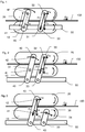
- the linear driving device represented at Figure 1 comprises a reference driving element, a caterpillar 10 attached to a supporting frame 50, and a moveable driving element and a caterpillar 20.
- the two caterpillars 10 and 20 are arranged together to apply an axial force Fa to an elongated element 100 placed between themselves.
- the elongated element 100 may either be a cable, a tube, a duct or an optical fiber.
- the linear driving device may also drive any kind of elongated element 100 with a constant cross section (such as an ellipse or polygon), or with a variable cross section, with a constant period.
- the caterpillars 10 and 20 are attached together by a first pivoting lever 30 and a second pivoting lever 40.
- the first pivoting lever 30 is connected to the reference driving caterpillar 10 by a rotation axis 31, and to the moveable driving caterpillar 20 by a rotation axis 32.
- the second pivoting lever 40 is connected to the reference driving caterpillar 10 by a rotation axis 41, and to the moveable driving caterpillar 20 by a rotation axis 42.
- the first and second pivoting levers are arranged so that the moveable driving caterpillar 20 has a circular trajectory within a first plane, and within this first plane, a first line passing through the rotation axes 31 and 32 is parallel to a second line passing through the rotation axes 41 and 42.
- the linear driving device is applying an axial force Fa to the elongated element 100.
- the moveable driving caterpillar 20 is powered by a motor (not shown) and rotates as represented by the arrow.
- the friction between the elongated element 100 and the moveable driving caterpillar 20 makes the moveable driving caterpillar 20 apply an axial force to the elongated element 100.
- This axial force in relation to the friction and in relation to the trajectory imposed to the moveable driving caterpillar 20 by the first and second pivoting levers 30 and 40, presses the moveable driving caterpillar 20 towards the reference driving caterpillar 10, thus creating a clamping force Fc.
- the friction combined to the axial force creates a downwards force Fc that presses the moveable driving caterpillar onto the elongated element.
- the reaction force Fr between the reference and moveable driving caterpillars 10 and 20 passes through the rotation axes 31-32 and 41-42, as shown.
- the clamping force Fc is then dependent on the angle ⁇ , which is the inclination between the line connecting the rotation axes 31-32 or 41-42 and a direction perpendicular to the axial force Fa.
- the predetermined angle ⁇ is dependent from the length L between the two rotation axes 31-32 and 41-42, so that an adjustment of this length L will affect the predetermined angle ⁇ and as a consequence, the clamping force Fc. It is thus possible to set the length L to a value so that the clamping force will have a magnitude adapted either to the maximum stress the elongated element can withstand or to increase in return the maximum axial force applied to the elongated element to correctly drive it.
- Figure 2 represents a second embodiment of the present invention.
- the reference driving caterpillar 10 and the moveable driving caterpillar 20 are both moveable relatively to the supporting frame 50 because the first pivoting lever 30 and the second pivoting lever 40 are both attached to the supporting frame 50.
- the first pivoting lever 30 is attached to the moveable driving caterpillar 20 by the rotation axis 32, and to the reference driving caterpillar 10 by the rotation axis 31.
- the second pivoting lever 40 is attached to the moveable driving caterpillar 20 by the rotation axis 42, and to the reference driving caterpillar 10 by the rotation axis 41.
- the moveable driving caterpillar 20 is powered by a motor (not shown) to apply to the elongated element 100 the axial force Fa, and is pressed towards the reference driving caterpillar 10 due to the friction between the elongated element 100 and the moveable driving caterpillar 20.
- the clamping force Fc depends on the predetermined angle ⁇ defined between the reaction force Fr passing through the rotation axes 31-32 or 41-42, and the direction perpendicular to the axial force Fa.
- Figure 3 represents a third embodiment of the invention.
- the reference driving caterpillar 10 and the moveable driving caterpillar 20 are both moveable relatively to the supporting frame 50 as the first pivoting lever 30 and the second pivoting lever 40 are both attached to the supporting frame 50.
- the difference with respect to the second embodiment is that the moveable driving caterpillar is only attached to the pivoting lever 40, increasing its degrees of freedom compared to the first and second embodiments, as the moveable driving caterpillar can freely rotate around the rotation axis 42.
- the second and third embodiments, with the first and second pivoting levers 30 and 40 respectively attached to the supporting frame 50 allow a vertical set up of the two driving caterpillars 10 and 20.
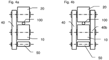
- Figure 4a is a side view of a first alternative of the second embodiment, showing that there are pivoting levers 40 arranged only at one side of the driving caterpillars 10 and 20.
- This alternative allows a swift and easy engagement or disengagement of the elongated element 100 between the two driving caterpillars 10 and 20, as one side is left free for access.
- Figure 4b is a side view of a second alternative of the second embodiment, showing that pivoting levers 40 and 40b are arranged on both sides of the driving caterpillars 10 and 20. This reduces the stress in the rotation axes, but the engagement or disengagement of the elongated element 100 between the driving caterpillars 10 and 20 may only be done through the free end of the elongated element 100.
- Another embodiment of the invention may consist in coupling any one of the pivoting levers with command means (a pneumatic or hydraulic cylinder, an elastic element, or an handle for example) to assist the movement of the pivoting levers and thus driving caterpillars to engage or disengage the elongated element 100, and/or to apply an additional clamping force during the driving of the elongated element.
- command means a pneumatic or hydraulic cylinder, an elastic element, or an handle for example
- all the embodiments of the present invention allow reversing the operating conditions, to push-pull the elongated element in two opposite directions.
- This set up is easily achieved by pivoting counterclockwise the represented pivoting levers 30 and 40 by an angle double that of the represented angle ⁇ .
- the reference and moveable driving caterpillars 10, 20 then have to be powered in the opposite angular rotation, to apply an axial force Fa' opposite to the represented axial force Fa, thus creating a clamping force dependent on the predetermined angle ⁇ .
- the need to remove the elongated element from the linear driving device and turning the linear driving device by 180° is avoided with such linear driving device having pivoting levers connecting the caterpillars.
- a linear and continuous pushing-pulling operation is possible with such linear driving device, and set up of the length between the rotation axes of the pivoting levers allows to adapt the clamping force.
Landscapes
- Engineering & Computer Science (AREA)
- Mechanical Engineering (AREA)
- Transmission Devices (AREA)
- Clamps And Clips (AREA)
- Knitting Machines (AREA)
Claims (9)
- Lineares Antriebsgerät, aufweisend:- ein Referenzantriebselement (10) und- ein bewegliches Antriebselement (20),wobei das lineare Antriebsgerät für ein Antreiben eines zwischen dem Referenzantriebselement (10) und dem beweglichen Antriebselement (20) angeordneten länglichen Elements (100) angeordnet ist,
wobei wenigstens eines von Referenzantriebselement (10) und beweglichem Antriebselement (20) angetrieben werden, um das längliche Element (100) mit einer Axialkraft (Fa) zu beaufschlagen, um es anzutreiben,
wobei das bewegliche Antriebselement (20) relativ zum Referenzantriebselement (10) beweglich ist, so dass die Axialkraft (Fa), kombiniert zu einer Reibung zwischen dem länglichen Element (100) und dem beweglichem Antriebselement (20), das bewegliche Antriebselement (20) gegen das Referenzantriebselement (10) drückt, um am länglichen Element (100) eine Klemmkraft (Fc) zu erzeugen, wobei:- das lineare Antriebsgerät wenigstens einen schwenkbaren Hebel (30, 40) aufweist, der über eine erste Rotationsachse (31, 41) am Referenzantriebselement (10) und über eine zweite Rotationsachse (32, 42) am beweglichen Antriebselement befestigt ist, und wobei,- wenn das längliche Element (100) angetrieben wird, der wenigstens eine schwenkbare Hebel (30, 40) so angeordnet ist, dass die Größe der Klemmkraft (Fc) von einem im Voraus zwischen einer rechtwinkligen Richtung zur Axialkraft (Fa) und einer Reaktionskraft (Fr) zwischen dem Referenzantriebselement (10) und dem beweglichen Antriebselement (20) definierten Winkel (α) abhängig ist und die erste (31, 41) und zweite (32, 42) Rotationsachse durchläuft,dadurch gekennzeichnet, dass der wenigstens eine schwenkbare Hebel (30, 40) Einstellmittel zum Einstellen eines Abstands zwischen der ersten Rotationsachse (31, 41) und der zweiten Rotationsachse (32, 42) und dadurch zum Einstellen des im Voraus bestimmten Winkels (α) aufweist - Lineares Antriebsgerät nach Anspruch 1, dadurch gekennzeichnet, dass- die zweite Rotationsachse (32, 42) entlang einer Kreisbahn in einer Bahnebene beweglich ist, und,- wenn das längliche Element (100) angetrieben wird, ist der im Voraus bestimmte Winkel (α) innerhalb der Bahnebene zwischen einer durch die erste (31, 41) und zweite (32, 42) Rotationsachse verlaufende Linie und einer rechtwinkligen Richtung zur Axialkraft (Fa) definiert.
- Lineares Antriebsgerät nach einem der Ansprüche 1 bis 2, wobei die erste Rotationsachse (31, 41) und/oder die zweite Rotationsachse (32, 42) an dem wenigstens einen schwenkbaren Hebel (30, 40) durch ein exzentrisches Gehäuse befestigt ist.
- Lineares Antriebsgerät nach einem der Ansprüche 1 bis 3, wobei das bewegliche Antriebselement (20) eine Raupe aufweist, die angetrieben ist, um das längliche Element (100) mit der Axialkraft (Fa) zu beaufschlagen.
- Lineares Antriebsgerät nach einem der Ansprüche 1 bis 4, wobei das Referenzantriebselement (10) eine Raupe aufweist, die angetrieben ist, um das längliche Element (100) mit einer zusätzlichen Axialkraft (Fa) zu beaufschlagen.
- Lineares Antriebsgerät nach einem der Ansprüche 1 bis 5, wobei das bewegliche Antriebselement (20), das Referenzantriebselement (10) und der wenigstens eine schwenkbare Hebel (30, 40), angeordnet in einer ersten geometrischen Konfiguration, eine erste Axialkraft (Fa) in einer ersten Richtung des länglichen Elements (100) ausübt, und wobei das bewegliche Antriebselement (20), das Referenzantriebselement (10) und der wenigstens eine schwenkbare Hebel (30, 40), angeordnet in einer zweiten geometrischen Konfiguration, eine zweite Axialkraft (Fa) in einer zweiten Richtung des länglichen Elements (100) entgegen der ersten Richtung des länglichen Elements (100) ausübt.
- Lineares Antriebsgerät nach Anspruch 6, wobei der im Voraus bestimmte Winkel (α) von der rechtwinkligen Richtung zur Reaktionskraft (Fr) in der ersten geometrischen Konfiguration einen ersten absoluten Wert hat und in einer ersten Winkelrichtung orientiert ist, und wobei der der im Voraus bestimmte Winkel (α) von der rechtwinkligen Richtung zur Reaktionskraft (Fr) in der zweiten geometrischen Konfiguration den gleichen absoluten Wert hat, aber in einer zweiten Winkelrichtung entgegen der ersten Winkelrichtung orientiert ist.
- Lineares Antriebsgerät nach einem der Ansprüche 1 bis 7, aufweisend einen Stützrahmen (50), wobei der wenigstens eine schwenkbare Hebel (30, 40) durch eine dritte Rotationsachse (33, 43) mit dem Stützrahmen (50) verbunden ist.
- Lineares Antriebsgerät nach einem der Ansprüche 1 bis 7, aufweisend einen zweiten schwenkbaren Hebel (40):- angebracht am Referenzantriebselement (10) durch eine vierte Rotationsachse (41) und am beweglichen Antriebselement (20) durch eine fünfte Rotationsachse (42), und- so angeordnet, dass eine durch die ersten (31) und zweiten (41) Achsen verlaufende Linie parallel zu einer durch die vierten (41) und fünften (42) Rotationsachsen verlaufende Linie verläuft.
Applications Claiming Priority (2)
| Application Number | Priority Date | Filing Date | Title |
|---|---|---|---|
| CH11732012 | 2012-07-27 | ||
| PCT/EP2013/065649 WO2014016355A1 (en) | 2012-07-27 | 2013-07-24 | Linear driving device with load dependent clamping capability |
Publications (2)
| Publication Number | Publication Date |
|---|---|
| EP2877422A1 EP2877422A1 (de) | 2015-06-03 |
| EP2877422B1 true EP2877422B1 (de) | 2016-04-20 |
Family
ID=48900966
Family Applications (1)
| Application Number | Title | Priority Date | Filing Date |
|---|---|---|---|
| EP13742428.9A Not-in-force EP2877422B1 (de) | 2012-07-27 | 2013-07-24 | Lineares antriebsgerät mit lastabhängiger klemmmöglichkeit |
Country Status (13)
| Country | Link |
|---|---|
| US (1) | US9834419B2 (de) |
| EP (1) | EP2877422B1 (de) |
| CN (1) | CN104507849B (de) |
| AU (1) | AU2013295009A1 (de) |
| BR (1) | BR112015001086A2 (de) |
| CA (1) | CA2878105A1 (de) |
| DK (1) | DK2877422T3 (de) |
| MY (1) | MY168253A (de) |
| PH (1) | PH12015500038A1 (de) |
| PL (1) | PL2877422T3 (de) |
| RU (1) | RU2015101925A (de) |
| SG (1) | SG11201408743WA (de) |
| WO (1) | WO2014016355A1 (de) |
Families Citing this family (3)
| Publication number | Priority date | Publication date | Assignee | Title |
|---|---|---|---|---|
| US10775566B2 (en) | 2015-10-27 | 2020-09-15 | Commscope, Inc. Of North Carolina | Fiber optic lane changers for use with fiber optic cables having unused optical fibers and related methods |
| GB2557543B (en) * | 2015-10-30 | 2021-08-25 | C/O Commscope Tech Llc | Cable clamp with a break assist mechanism |
| EP4088352A1 (de) | 2020-01-07 | 2022-11-16 | CommScope Technologies LLC | Verbindungskabelklemme mit kontrolliertem kabelabschnitt |
Family Cites Families (11)
| Publication number | Priority date | Publication date | Assignee | Title |
|---|---|---|---|---|
| CA785245A (en) * | 1968-05-14 | Demeter Jozsef | Production of plastic coated carriers | |
| US2792104A (en) | 1956-01-05 | 1957-05-14 | Goodman Mfg Co | Drive for belt conveyors |
| US3118635A (en) | 1962-11-13 | 1964-01-21 | Perry E Landsem | Line reeling control means |
| CH429584A (de) * | 1964-10-16 | 1967-01-31 | Stolze Richard Ing Dr | Antrieb für Kettenförderer |
| DE1950919A1 (de) | 1968-12-26 | 1970-07-09 | Morgan Const Company | Vorrichtung zum Antrieb eines sich in axialer Richtung bewegenden laenglichen Materials |
| GB1273271A (en) * | 1969-01-02 | 1972-05-03 | Chance Brothers Ltd | Improvements in or relating to glass gripping devices |
| DE2942110A1 (de) | 1979-10-18 | 1981-04-30 | Gustav 5800 Hagen Rölle | Vorrichtung zum antrieb von langgestreckten gegenstaenden |
| US5072637A (en) | 1990-04-30 | 1991-12-17 | Sealed Air Corporation | Apparatus and method for segmenting continuous webs into predetermined lengths |
| JP3091325B2 (ja) | 1992-08-25 | 2000-09-25 | 松下電工株式会社 | 車輛用照明装置 |
| IT1316115B1 (it) | 2000-01-21 | 2003-03-28 | Hans Guenter Czaloun | Apparecchio di trazione a fune passante a movimento continuo. |
| JP5596374B2 (ja) | 2010-03-04 | 2014-09-24 | 株式会社関電工 | 中高層ビルにおける垂直幹線の延線工法及びこれに使用する装置 |
-
2013
- 2013-07-24 US US14/415,919 patent/US9834419B2/en not_active Expired - Fee Related
- 2013-07-24 CN CN201380039579.6A patent/CN104507849B/zh not_active Expired - Fee Related
- 2013-07-24 AU AU2013295009A patent/AU2013295009A1/en not_active Abandoned
- 2013-07-24 WO PCT/EP2013/065649 patent/WO2014016355A1/en not_active Ceased
- 2013-07-24 CA CA2878105A patent/CA2878105A1/en not_active Abandoned
- 2013-07-24 EP EP13742428.9A patent/EP2877422B1/de not_active Not-in-force
- 2013-07-24 RU RU2015101925A patent/RU2015101925A/ru not_active Application Discontinuation
- 2013-07-24 MY MYPI2014003545A patent/MY168253A/en unknown
- 2013-07-24 BR BR112015001086A patent/BR112015001086A2/pt not_active IP Right Cessation
- 2013-07-24 PL PL13742428.9T patent/PL2877422T3/pl unknown
- 2013-07-24 DK DK13742428.9T patent/DK2877422T3/en active
- 2013-07-24 SG SG11201408743WA patent/SG11201408743WA/en unknown
-
2015
- 2015-01-07 PH PH12015500038A patent/PH12015500038A1/en unknown
Non-Patent Citations (1)
| Title |
|---|
| None * |
Also Published As
| Publication number | Publication date |
|---|---|
| US20150183623A1 (en) | 2015-07-02 |
| DK2877422T3 (en) | 2016-05-30 |
| RU2015101925A (ru) | 2016-08-20 |
| CN104507849A (zh) | 2015-04-08 |
| EP2877422A1 (de) | 2015-06-03 |
| BR112015001086A2 (pt) | 2017-06-27 |
| CA2878105A1 (en) | 2014-01-30 |
| AU2013295009A1 (en) | 2015-01-29 |
| SG11201408743WA (en) | 2015-01-29 |
| US9834419B2 (en) | 2017-12-05 |
| CN104507849B (zh) | 2016-10-19 |
| MY168253A (en) | 2018-10-16 |
| PH12015500038A1 (en) | 2015-03-16 |
| WO2014016355A1 (en) | 2014-01-30 |
| PL2877422T3 (pl) | 2016-09-30 |
Similar Documents
| Publication | Publication Date | Title |
|---|---|---|
| EP2877422B1 (de) | Lineares antriebsgerät mit lastabhängiger klemmmöglichkeit | |
| CN1021211C (zh) | 有皮带收卷器的座椅安全带系统的皮带夹紧装置 | |
| EP2794459B1 (de) | Trommeleinheit für einen bohrlocheingriffsstrang | |
| US10874054B2 (en) | Park brake and traction drive bypass interlock | |
| CA2788559A1 (en) | Windlass system and method | |
| US10246311B2 (en) | Winch | |
| US20250230012A1 (en) | Hose reel | |
| CN117566539A (zh) | 一种电力施工用具有保护功能的线缆输送装置 | |
| US20080164107A1 (en) | Apparatus and method for operating a take-up mechanism in a locomotive braking system | |
| KR102364912B1 (ko) | 매우 긴 관형 물체를 견인하기 위한 디바이스 | |
| EP2878569B1 (de) | Winde mit einer Anordnung zur Steuerung dessen Kabels | |
| US10604239B2 (en) | Method for rotationally driving the wheel of an airplane | |
| RU2598113C2 (ru) | Блок безопасности подъёмника | |
| CN1977088B (zh) | 卷帘门装置 | |
| EP2407334B1 (de) | Stromschaltvorrichtung für ein Fahrzeug | |
| RU2769319C1 (ru) | Трос аварийного отключения для конвейера | |
| JP2022064963A (ja) | 切断装置 | |
| KR20200011722A (ko) | 클러치 액추에이터용 마모보상장치 | |
| GB2336348A (en) | Winch rope guide | |
| KR102296650B1 (ko) | 매우 긴 관형 물체를 견인하기 위한 디바이스 | |
| KR200465157Y1 (ko) | 케이블 가이드 어셈블리 | |
| CN105522948A (zh) | 一种运输货物的安全紧固装置及其运行方法 | |
| KR101057843B1 (ko) | 상용차의 센터 파킹 브레이크 장치 | |
| NZ560922A (en) | Cable winch operated vehicle mounted tipping deck |
Legal Events
| Date | Code | Title | Description |
|---|---|---|---|
| PUAI | Public reference made under article 153(3) epc to a published international application that has entered the european phase |
Free format text: ORIGINAL CODE: 0009012 |
|
| 17P | Request for examination filed |
Effective date: 20141219 |
|
| AK | Designated contracting states |
Kind code of ref document: A1 Designated state(s): AL AT BE BG CH CY CZ DE DK EE ES FI FR GB GR HR HU IE IS IT LI LT LU LV MC MK MT NL NO PL PT RO RS SE SI SK SM TR |
|
| AX | Request for extension of the european patent |
Extension state: BA ME |
|
| RAP1 | Party data changed (applicant data changed or rights of an application transferred) |
Owner name: PLUMETTAZ HOLDING S.A. |
|
| DAX | Request for extension of the european patent (deleted) | ||
| GRAP | Despatch of communication of intention to grant a patent |
Free format text: ORIGINAL CODE: EPIDOSNIGR1 |
|
| GRAS | Grant fee paid |
Free format text: ORIGINAL CODE: EPIDOSNIGR3 |
|
| INTG | Intention to grant announced |
Effective date: 20160204 |
|
| GRAA | (expected) grant |
Free format text: ORIGINAL CODE: 0009210 |
|
| AK | Designated contracting states |
Kind code of ref document: B1 Designated state(s): AL AT BE BG CH CY CZ DE DK EE ES FI FR GB GR HR HU IE IS IT LI LT LU LV MC MK MT NL NO PL PT RO RS SE SI SK SM TR |
|
| REG | Reference to a national code |
Ref country code: GB Ref legal event code: FG4D |
|
| REG | Reference to a national code |
Ref country code: CH Ref legal event code: NV Representative=s name: NOVAGRAAF INTERNATIONAL SA, CH Ref country code: CH Ref legal event code: EP |
|
| REG | Reference to a national code |
Ref country code: AT Ref legal event code: REF Ref document number: 792217 Country of ref document: AT Kind code of ref document: T Effective date: 20160515 |
|
| REG | Reference to a national code |
Ref country code: IE Ref legal event code: FG4D |
|
| REG | Reference to a national code |
Ref country code: DK Ref legal event code: T3 Effective date: 20160527 |
|
| REG | Reference to a national code |
Ref country code: NL Ref legal event code: FP |
|
| REG | Reference to a national code |
Ref country code: DE Ref legal event code: R096 Ref document number: 602013006809 Country of ref document: DE |
|
| REG | Reference to a national code |
Ref country code: SE Ref legal event code: TRGR |
|
| REG | Reference to a national code |
Ref country code: FR Ref legal event code: PLFP Year of fee payment: 4 |
|
| REG | Reference to a national code |
Ref country code: LT Ref legal event code: MG4D |
|
| PG25 | Lapsed in a contracting state [announced via postgrant information from national office to epo] |
Ref country code: FI Free format text: LAPSE BECAUSE OF FAILURE TO SUBMIT A TRANSLATION OF THE DESCRIPTION OR TO PAY THE FEE WITHIN THE PRESCRIBED TIME-LIMIT Effective date: 20160420 Ref country code: LT Free format text: LAPSE BECAUSE OF FAILURE TO SUBMIT A TRANSLATION OF THE DESCRIPTION OR TO PAY THE FEE WITHIN THE PRESCRIBED TIME-LIMIT Effective date: 20160420 Ref country code: NO Free format text: LAPSE BECAUSE OF FAILURE TO SUBMIT A TRANSLATION OF THE DESCRIPTION OR TO PAY THE FEE WITHIN THE PRESCRIBED TIME-LIMIT Effective date: 20160720 |
|
| PG25 | Lapsed in a contracting state [announced via postgrant information from national office to epo] |
Ref country code: HR Free format text: LAPSE BECAUSE OF FAILURE TO SUBMIT A TRANSLATION OF THE DESCRIPTION OR TO PAY THE FEE WITHIN THE PRESCRIBED TIME-LIMIT Effective date: 20160420 Ref country code: RS Free format text: LAPSE BECAUSE OF FAILURE TO SUBMIT A TRANSLATION OF THE DESCRIPTION OR TO PAY THE FEE WITHIN THE PRESCRIBED TIME-LIMIT Effective date: 20160420 Ref country code: ES Free format text: LAPSE BECAUSE OF FAILURE TO SUBMIT A TRANSLATION OF THE DESCRIPTION OR TO PAY THE FEE WITHIN THE PRESCRIBED TIME-LIMIT Effective date: 20160420 Ref country code: LV Free format text: LAPSE BECAUSE OF FAILURE TO SUBMIT A TRANSLATION OF THE DESCRIPTION OR TO PAY THE FEE WITHIN THE PRESCRIBED TIME-LIMIT Effective date: 20160420 Ref country code: PT Free format text: LAPSE BECAUSE OF FAILURE TO SUBMIT A TRANSLATION OF THE DESCRIPTION OR TO PAY THE FEE WITHIN THE PRESCRIBED TIME-LIMIT Effective date: 20160822 Ref country code: GR Free format text: LAPSE BECAUSE OF FAILURE TO SUBMIT A TRANSLATION OF THE DESCRIPTION OR TO PAY THE FEE WITHIN THE PRESCRIBED TIME-LIMIT Effective date: 20160721 |
|
| PG25 | Lapsed in a contracting state [announced via postgrant information from national office to epo] |
Ref country code: BE Free format text: LAPSE BECAUSE OF FAILURE TO SUBMIT A TRANSLATION OF THE DESCRIPTION OR TO PAY THE FEE WITHIN THE PRESCRIBED TIME-LIMIT Effective date: 20160420 |
|
| REG | Reference to a national code |
Ref country code: DE Ref legal event code: R097 Ref document number: 602013006809 Country of ref document: DE |
|
| PG25 | Lapsed in a contracting state [announced via postgrant information from national office to epo] |
Ref country code: SK Free format text: LAPSE BECAUSE OF FAILURE TO SUBMIT A TRANSLATION OF THE DESCRIPTION OR TO PAY THE FEE WITHIN THE PRESCRIBED TIME-LIMIT Effective date: 20160420 Ref country code: EE Free format text: LAPSE BECAUSE OF FAILURE TO SUBMIT A TRANSLATION OF THE DESCRIPTION OR TO PAY THE FEE WITHIN THE PRESCRIBED TIME-LIMIT Effective date: 20160420 Ref country code: RO Free format text: LAPSE BECAUSE OF FAILURE TO SUBMIT A TRANSLATION OF THE DESCRIPTION OR TO PAY THE FEE WITHIN THE PRESCRIBED TIME-LIMIT Effective date: 20160420 Ref country code: CZ Free format text: LAPSE BECAUSE OF FAILURE TO SUBMIT A TRANSLATION OF THE DESCRIPTION OR TO PAY THE FEE WITHIN THE PRESCRIBED TIME-LIMIT Effective date: 20160420 |
|
| PLBE | No opposition filed within time limit |
Free format text: ORIGINAL CODE: 0009261 |
|
| STAA | Information on the status of an ep patent application or granted ep patent |
Free format text: STATUS: NO OPPOSITION FILED WITHIN TIME LIMIT |
|
| PG25 | Lapsed in a contracting state [announced via postgrant information from national office to epo] |
Ref country code: SM Free format text: LAPSE BECAUSE OF FAILURE TO SUBMIT A TRANSLATION OF THE DESCRIPTION OR TO PAY THE FEE WITHIN THE PRESCRIBED TIME-LIMIT Effective date: 20160420 |
|
| 26N | No opposition filed |
Effective date: 20170123 |
|
| PG25 | Lapsed in a contracting state [announced via postgrant information from national office to epo] |
Ref country code: MC Free format text: LAPSE BECAUSE OF FAILURE TO SUBMIT A TRANSLATION OF THE DESCRIPTION OR TO PAY THE FEE WITHIN THE PRESCRIBED TIME-LIMIT Effective date: 20160420 |
|
| REG | Reference to a national code |
Ref country code: IE Ref legal event code: MM4A |
|
| PG25 | Lapsed in a contracting state [announced via postgrant information from national office to epo] |
Ref country code: SI Free format text: LAPSE BECAUSE OF FAILURE TO SUBMIT A TRANSLATION OF THE DESCRIPTION OR TO PAY THE FEE WITHIN THE PRESCRIBED TIME-LIMIT Effective date: 20160420 |
|
| REG | Reference to a national code |
Ref country code: FR Ref legal event code: PLFP Year of fee payment: 5 |
|
| PG25 | Lapsed in a contracting state [announced via postgrant information from national office to epo] |
Ref country code: IE Free format text: LAPSE BECAUSE OF NON-PAYMENT OF DUE FEES Effective date: 20160724 |
|
| PG25 | Lapsed in a contracting state [announced via postgrant information from national office to epo] |
Ref country code: LU Free format text: LAPSE BECAUSE OF NON-PAYMENT OF DUE FEES Effective date: 20160724 |
|
| REG | Reference to a national code |
Ref country code: AT Ref legal event code: UEP Ref document number: 792217 Country of ref document: AT Kind code of ref document: T Effective date: 20160420 |
|
| PG25 | Lapsed in a contracting state [announced via postgrant information from national office to epo] |
Ref country code: HU Free format text: LAPSE BECAUSE OF FAILURE TO SUBMIT A TRANSLATION OF THE DESCRIPTION OR TO PAY THE FEE WITHIN THE PRESCRIBED TIME-LIMIT; INVALID AB INITIO Effective date: 20130724 |
|
| PG25 | Lapsed in a contracting state [announced via postgrant information from national office to epo] |
Ref country code: CY Free format text: LAPSE BECAUSE OF FAILURE TO SUBMIT A TRANSLATION OF THE DESCRIPTION OR TO PAY THE FEE WITHIN THE PRESCRIBED TIME-LIMIT Effective date: 20160420 Ref country code: MK Free format text: LAPSE BECAUSE OF FAILURE TO SUBMIT A TRANSLATION OF THE DESCRIPTION OR TO PAY THE FEE WITHIN THE PRESCRIBED TIME-LIMIT Effective date: 20160420 Ref country code: IS Free format text: LAPSE BECAUSE OF FAILURE TO SUBMIT A TRANSLATION OF THE DESCRIPTION OR TO PAY THE FEE WITHIN THE PRESCRIBED TIME-LIMIT Effective date: 20160420 Ref country code: MT Free format text: LAPSE BECAUSE OF NON-PAYMENT OF DUE FEES Effective date: 20160731 |
|
| REG | Reference to a national code |
Ref country code: FR Ref legal event code: PLFP Year of fee payment: 6 |
|
| PG25 | Lapsed in a contracting state [announced via postgrant information from national office to epo] |
Ref country code: BG Free format text: LAPSE BECAUSE OF FAILURE TO SUBMIT A TRANSLATION OF THE DESCRIPTION OR TO PAY THE FEE WITHIN THE PRESCRIBED TIME-LIMIT Effective date: 20160420 |
|
| PG25 | Lapsed in a contracting state [announced via postgrant information from national office to epo] |
Ref country code: AL Free format text: LAPSE BECAUSE OF FAILURE TO SUBMIT A TRANSLATION OF THE DESCRIPTION OR TO PAY THE FEE WITHIN THE PRESCRIBED TIME-LIMIT Effective date: 20160420 Ref country code: TR Free format text: LAPSE BECAUSE OF FAILURE TO SUBMIT A TRANSLATION OF THE DESCRIPTION OR TO PAY THE FEE WITHIN THE PRESCRIBED TIME-LIMIT Effective date: 20160420 |
|
| PGFP | Annual fee paid to national office [announced via postgrant information from national office to epo] |
Ref country code: PL Payment date: 20190717 Year of fee payment: 7 |
|
| PGFP | Annual fee paid to national office [announced via postgrant information from national office to epo] |
Ref country code: NL Payment date: 20210723 Year of fee payment: 9 |
|
| PGFP | Annual fee paid to national office [announced via postgrant information from national office to epo] |
Ref country code: IT Payment date: 20210730 Year of fee payment: 9 Ref country code: FR Payment date: 20210728 Year of fee payment: 9 Ref country code: AT Payment date: 20210720 Year of fee payment: 9 |
|
| PGFP | Annual fee paid to national office [announced via postgrant information from national office to epo] |
Ref country code: DK Payment date: 20210721 Year of fee payment: 9 Ref country code: SE Payment date: 20210721 Year of fee payment: 9 Ref country code: GB Payment date: 20210728 Year of fee payment: 9 Ref country code: CH Payment date: 20210727 Year of fee payment: 9 Ref country code: DE Payment date: 20210721 Year of fee payment: 9 |
|
| PG25 | Lapsed in a contracting state [announced via postgrant information from national office to epo] |
Ref country code: PL Free format text: LAPSE BECAUSE OF NON-PAYMENT OF DUE FEES Effective date: 20200724 |
|
| REG | Reference to a national code |
Ref country code: DE Ref legal event code: R119 Ref document number: 602013006809 Country of ref document: DE |
|
| REG | Reference to a national code |
Ref country code: DK Ref legal event code: EBP Effective date: 20220731 |
|
| REG | Reference to a national code |
Ref country code: CH Ref legal event code: PL Ref country code: SE Ref legal event code: EUG |
|
| REG | Reference to a national code |
Ref country code: NL Ref legal event code: MM Effective date: 20220801 |
|
| REG | Reference to a national code |
Ref country code: AT Ref legal event code: MM01 Ref document number: 792217 Country of ref document: AT Kind code of ref document: T Effective date: 20220724 |
|
| GBPC | Gb: european patent ceased through non-payment of renewal fee |
Effective date: 20220724 |
|
| PG25 | Lapsed in a contracting state [announced via postgrant information from national office to epo] |
Ref country code: SE Free format text: LAPSE BECAUSE OF NON-PAYMENT OF DUE FEES Effective date: 20220725 Ref country code: LI Free format text: LAPSE BECAUSE OF NON-PAYMENT OF DUE FEES Effective date: 20220731 Ref country code: FR Free format text: LAPSE BECAUSE OF NON-PAYMENT OF DUE FEES Effective date: 20220731 Ref country code: CH Free format text: LAPSE BECAUSE OF NON-PAYMENT OF DUE FEES Effective date: 20220731 Ref country code: AT Free format text: LAPSE BECAUSE OF NON-PAYMENT OF DUE FEES Effective date: 20220724 |
|
| PG25 | Lapsed in a contracting state [announced via postgrant information from national office to epo] |
Ref country code: GB Free format text: LAPSE BECAUSE OF NON-PAYMENT OF DUE FEES Effective date: 20220724 Ref country code: DE Free format text: LAPSE BECAUSE OF NON-PAYMENT OF DUE FEES Effective date: 20230201 |
|
| PG25 | Lapsed in a contracting state [announced via postgrant information from national office to epo] |
Ref country code: NL Free format text: LAPSE BECAUSE OF NON-PAYMENT OF DUE FEES Effective date: 20220801 |
|
| PG25 | Lapsed in a contracting state [announced via postgrant information from national office to epo] |
Ref country code: IT Free format text: LAPSE BECAUSE OF NON-PAYMENT OF DUE FEES Effective date: 20220724 Ref country code: DK Free format text: LAPSE BECAUSE OF NON-PAYMENT OF DUE FEES Effective date: 20220731 |