EP2877287B1 - Pill crushing system - Google Patents
Pill crushing system Download PDFInfo
- Publication number
- EP2877287B1 EP2877287B1 EP13822505.7A EP13822505A EP2877287B1 EP 2877287 B1 EP2877287 B1 EP 2877287B1 EP 13822505 A EP13822505 A EP 13822505A EP 2877287 B1 EP2877287 B1 EP 2877287B1
- Authority
- EP
- European Patent Office
- Prior art keywords
- cup holder
- cup
- axial translation
- pill
- fixture
- Prior art date
- Legal status (The legal status is an assumption and is not a legal conclusion. Google has not performed a legal analysis and makes no representation as to the accuracy of the status listed.)
- Not-in-force
Links
- 239000006187 pill Substances 0.000 title claims description 77
- 239000000463 material Substances 0.000 claims description 12
- 239000000843 powder Substances 0.000 description 17
- 239000002245 particle Substances 0.000 description 13
- 230000005012 migration Effects 0.000 description 8
- 238000013508 migration Methods 0.000 description 8
- 230000000295 complement effect Effects 0.000 description 4
- 239000000654 additive Substances 0.000 description 2
- 230000000996 additive effect Effects 0.000 description 2
- 230000004888 barrier function Effects 0.000 description 2
- 239000002778 food additive Substances 0.000 description 2
- 239000012634 fragment Substances 0.000 description 2
- 235000011389 fruit/vegetable juice Nutrition 0.000 description 2
- 239000007788 liquid Substances 0.000 description 2
- 235000021056 liquid food Nutrition 0.000 description 2
- 239000000203 mixture Substances 0.000 description 2
- 239000004570 mortar (masonry) Substances 0.000 description 2
- 239000002002 slurry Substances 0.000 description 2
- 230000009747 swallowing Effects 0.000 description 2
- 230000009471 action Effects 0.000 description 1
- 230000002411 adverse Effects 0.000 description 1
- 230000000903 blocking effect Effects 0.000 description 1
- 238000012864 cross contamination Methods 0.000 description 1
- 230000008821 health effect Effects 0.000 description 1
- 230000002401 inhibitory effect Effects 0.000 description 1
- 230000013011 mating Effects 0.000 description 1
- 230000000474 nursing effect Effects 0.000 description 1
- 238000002360 preparation method Methods 0.000 description 1
- 235000011962 puddings Nutrition 0.000 description 1
Images










Classifications
-
- A—HUMAN NECESSITIES
- A61—MEDICAL OR VETERINARY SCIENCE; HYGIENE
- A61J—CONTAINERS SPECIALLY ADAPTED FOR MEDICAL OR PHARMACEUTICAL PURPOSES; DEVICES OR METHODS SPECIALLY ADAPTED FOR BRINGING PHARMACEUTICAL PRODUCTS INTO PARTICULAR PHYSICAL OR ADMINISTERING FORMS; DEVICES FOR ADMINISTERING FOOD OR MEDICINES ORALLY; BABY COMFORTERS; DEVICES FOR RECEIVING SPITTLE
- A61J7/00—Devices for administering medicines orally, e.g. spoons; Pill counting devices; Arrangements for time indication or reminder for taking medicine
- A61J7/0007—Pill breaking or crushing devices
Definitions
- the present invention relates to pill crushing systems, and more particularly relates to a pill chip guard which acts to inhibit pill chips from escaping the pill crushing chamber during the pill crushing operation.
- the invention relates to nestable cups having improved pill crushing features and interfacing dimensions which inhibit migration of the powdered pill material from reaching the top perimeters of the cups.
- the grinding or crushing of pills into powder form may be necessary when, for example, the person has trouble swallowing whole pills due to throat problems. This is a common need in nursing homes and hospitals. While the very first pill crushing device was most likely the mortar and pestle (which is still used today), more technologically advanced pill crushing devices have been developed over the years (manually or electrically driven) which have various designs that offer advantages over the mortar and pestle, such as making the pill crushing operation quicker, easier and safer (e.g., by preventing cross-contamination between different Rx pills ground in succession), for example.
- Some pill crushing devices utilize a pair of disposable cups which may be nested together with the pill located therebetween. As one cup is rotated relative to the other cup, the pill is ground into a powder. The top cup is removed, leaving the powered pill inside the bottom cup.
- An additive such as juice or applesauce, for example, may be added to the cup and mixed with the powder to form a liquid or slurry which the patient may more easily swallow.
- An example of such a nested cup pill crushing device may be seen in commonly owned U.S. Patent Publication No. US 2012/0160946 . While the device of the '946 publication provides advances over the prior art, there remains a possibility that some pill chips may unintentionally escape from between the cups during the crushing operation.
- the present invention addresses the above concern of pill chips escaping from between the cups by providing a chip guard positioned to physically block pill chips from exiting between the nested cups during the pill crushing operation.
- the present invention provides improved nested cup designs which enhance distribution of the pill material between the facing surfaces of the cups during the crushing operation, yet also inhibit the migration of the fine powder from reaching the top open perimeters of the nesting cups. Forcing the pill material as it is being crushed to spread out between a larger surface area increases the amount of pill material subjected to the frictional grinding forces of the nested cups and thereby forms a finer powder than achieved by prior art nested cup designs.
- including interfacing cup geometries which inhibit migration of the fine powder to the open cup perimeters prevents the loss of pill material from between the open edges of the cups.
- the present invention provides a pill crushing machine having a bottom cup holder positioned in a main housing and a top cup holder positioned on the inside of a lid hinged to the main housing.
- a pair of nestable cups are provided for removable placement in the pill crushing machine.
- the bottom cup is placed upon the bottom cup holder with the pills to be crushed placed inside the bottom cup.
- the top cup is nested inside the bottom cup with the pills located between the nested bottom and top cups and the lid is moved to the closed position.
- the machine is activated causing the bottom cup to rise up against and then rotate relative to the stationary top cup.
- the resultant forces and friction between the bottom and top cups cause the pills located therebetween to be crushed and ground into a powder.
- a liquid food additive such as juice, applesauce, pudding or the like may be mixed with the powder to form a slurry and given to the patient in a now more easily swallowed form. While described as having a rotating bottom cup and stationary top cup, it is envision that a machine can operate in an inverse relation wherein the top cup rotates and the bottom cup is stationary.
- the pill crushing machine biases the nested cups toward one another.
- the pills undergo the crushing operation, they begin to crack and pulverize into smaller and smaller particles that migrate radially outwardly along the facing surfaces of the cups and, depending on the amount of pill material to be crushed, potentially also up the facing side walls of the cups toward the open top perimeters thereof.
- a small gap may exist between the open top perimeters of the bottom and top cups. This creates an area wherethrough pill particles may escape from between the cups. This is undesirable in that any portion of the pills being crushed that do not remain in the cup are lost and the prescribed dose is thereby being unknowingly reduced which could potentially result in adverse health effects on the patient.
- the present invention provides a pill crushing machine with a physical barrier at the location of the nested cups perimeter gap which acts as a "chip guard" to inhibit the escape of pill particles through this gap.
- the chip guard is in the form of a ring which is movable between an active guard position and a retracted cup access position allowing easy access to the nested cups into and out of the machine.
- the ring wall In the active guard position, the ring wall encircles and lies in close proximity to the gap between the nested cups top perimeters, thereby forming a physical barrier to pill particles which may otherwise escape from between the cups at this gap.
- the present disclosure provides a pair of nestable cups for a pill crushing machine wherein the bottom cup and top cup have different side wall angles to promote improved pill crushing and inhibit migration of the powdered pill material from reaching the open gap between the cup top perimeters.
- the respective cup dimensions are selected so as to cause more pronounced migration of the pill particles in a radially outward direction along the facing cup walls. Radial and even migration of the pill particles between the cups is desirable in that the more cup surface area that is actively grinding against the pill particles, the more pill particles will be subject to continuous grinding which results in a finer (smaller) resultant particle size. The finer the resultant powder, the better the powder will mix with the liquid food additive which will be easier to swallow for the patient than a mixture having larger pill particles therein. Furthermore, since the interfacing geometries of the nested cup side walls are such as to inhibit the fine powder from reaching the open top perimeters of the cups, the full amount of finely powdered pill material stays between the cups, and within the bottom cup.
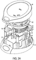
- a pill crushing machine designated generally by the reference numeral 10 having a main housing body 12 and lid 14 which is hinge connected to housing body 12 via hinge elements 12a and 14a (see Figs. 1 and 2 ). While the housing body 12 seen in Fig. 1 is not shown in the remaining figures for the sake of clarity, it is understood that it would extend between base 13 and lid 14 (see Figs. 3A-5 ).
- a pair of nestable cups 16 and 18 are provided for use with machine 10 which are preferably single use and formed of a suitable plastic.
- bottom cup 16 and top cup 18 have different dimensions, with top cup 18 (which nests inside bottom cup 16 with pills "P" to be crushed deposited therebetween as seen in Fig. 8A ) being overall generally smaller and having side walls 18a and 18b (which meet at line 18L) which are straight in the direction from lower wall segment 18b to upper perimeter flange 18c (seen best in the cross-section of Fig. 6D and 8A and 8B ).
- Upper wall segment 18a extends at an angle A1 of about 100° with respect to perimeter flange 18c, and lower wall segment 18b extending at an angle A2 of about 170° with respect to upper wall segment 18a.
- upper wall segment 16a of bottom cup 16 includes having an outwardly curved surface having a radius of about 1.380mm and a lower wall segment 16b (which meets upper wall segment 18a at line 18L) having an inwardly curved surface having a radius of about 1.662mm.
- the inwardly curved lower wall segment 16b interfaces closely with top cup lower segment wall 18b to promote fine grinding of the pill particles therebetween while the outwardly curved surface of bottom cup upper wall segment 16a interfaces with the sharper angled (i.e., more vertically inclined that the lower wall segment) straight upper wall segment 18a of top cup 18 so as to create a large enough space to inhibit pill powder migration as explained further below.
- the cup bottom walls 16d and 18d are of a non-planar configuration and include a radial pattern of fluted sections 16d' and 18d', respectively.
- Top cup perimeter flange 18c includes a plurality of annularly spaced, upwardly-facing (in a direction away from bottom wall 18d) protrusions 18e
- bottom cup perimeter flange 16c includes a plurality of annularly spaced, downwardly-facing (in a direction toward bottom wall 16d) protrusions 16e, the purpose of which is described below.
- Lid 14 includes a top cup holder 20 having a geometry complimentary to the geometry of the respective inside surfaces of the top cup 18 to be removably placed thereon which thus forms a mating fit between the two when the top cup 18 is removably mounted onto the top cup holder 20.
- a spring loaded plunger 21 may be provided at approximately the center of top cup holder 20 which biases the top cup 18 against the bottom cup 16 when the lid is closed.
- top cup protrusions 18e may be aligned and engaged with complementary spaced, respective recesses 20a formed about the perimeter of top cup holder 20 (see Fig. 2 ).
- Bottom cup 16 may be removably positioned within complementary shaped bottom cup holder 22. To ensure that bottom cup 16 will rotate together with bottom cup holder 22 during the pill crushing operation, bottom cup protrusions 16e may align with and be engaged with complementary spaced respective recesses 22a formed about the perimeter of bottom cup holder 22.
- Bottom cup holder 22 ( Figs. 3-5 and 13 ) includes a bottom wall 22a, side wall 22b and top perimeter edge 22c having a plurality of annularly spaced recesses 22d which may align with and engage protrusions 16e of bottom cup 16 when placed therein.
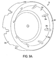
- Bottom cup holder 22 fits within the complementary shaped center recess 24a of rotator base element 24 (see also Figs. 9A and 9B ).
- Rotator base element 24 includes a lower wall segment 24b which is radially spaced from a center stem 24c having a plurality of annularly spaced vanes 24d extending radially outwardly therefrom (see Fig. 9B ).
- Bottom cup holder 22 includes a plurality of annularly spaced rib elements 22e which may align with and engage a like plurality of annularly spaced openings 24e formed along the lip 24f and extending partly down the side wall 24g thereof (see Fig. 9A ). As such, bottom cup holder 22 is rotationally fixed to rotator base element 24.
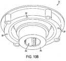
- Rotator base element 24 may be rotationally fixed to a second base element 26 via vanes 24d aligning with and fitting within respective walled slots 26b which radially extend from center aperture 26a (see Figs. 4 , 9B and 10A ).
- Second base element 26 includes a lower annular wall segment 26c defining a center bore 26d (see Fig. 10B ).
- a third base element 36 (see Figs. 4 , 5 and 12 ) includes a center stem portion 36c which telescopes into center bore 26d of second base element 26.
- third base element 36 further includes a ring element 36a which lies concentrically radially outwardly of center stem portion 36c which forms an annular channel 36d therebetween. With center stem portion 36c inserted into center bore 26d, annular wall segment 26c resides within annular channel 36d (see Fig. 4 ).
- Third base element is seen to further include a shoulder portion 36b and stem portion 36e having a center bore 36g into which the output shaft of a drive motor (not shown) positioned there beneath may extend.
- Shoulder portion 36b is further seen to taper in a spiral fashion from a minimum width portion 36b' to a maximum width portion 36b" which forms a step 36b'" for reasons explained below.
- a first axial translation element 30 having internal threads 30a and external splined surface 30c (see Figs. 4 , 5 and 11 ) is fixed to second base element 26, e.g., via screws passed through holes 30b which align with respective holes 26f (see also Fig. 10B ).
- a second axial translation element 34 is provided having threads 34a on the outer wall surface thereof and terminating in a ledge portion 34b ( Fig. 14 ). The lower surface 34c is seated against shoulder portion 36b of third base element 36 ( Fig. 12 ) with ledge portion 34b abutting step 36b"'. Second axial translation element 34 resides within first axial translation element 30 with threads 30a engaging threads 34a (see Fig. 4 ).
- Third base element stem portion 36e extends into a center bore 40a of a housing mount 40 with stem clips 36f ( Fig. 12 ) engaging and fixing third base element 36 to mount 40. Shoulder portion 36b is thus seated upon ledge 40b of housing mount 40.
- a chip guard 50 ( Figs. 4 and 5 ) is provided which encircles the nesting cups 16, 18 within machine 10.
- cups 16,18 are not shown for the sake of clarity, but would reside in the space “S” between top cup holder 20 and bottom cup holder.
- the juncture of the cup perimeters wherein gap "G" is formed ( Fig. 8 ) would reside in area indicated by reference arrow SG in Fig. 4 .
- chip guard wall segment 50a located radially outwardly of space SG, any pill fragments "F" which could otherwise escape through this area are physically blocked by the chip guard.
- chip guard 50 has a length extending from top cup holder base wall 20a to a position along rotator base element outer side wall 24e.
- a ring element 52 is provided which attaches to chip guard 50 via clips 50b integrally formed in the chip guard 50.
- One or more spring loaded plunger elements 54 connect ring 50 to second base element 26 at holes 26'. As such, spring loaded plunger elements 54 act to bias ring 52 and hence also chip guard 50 toward and against top cup holder base 20a.
- one or more notches 50c may be provided adjacent the top edge 50d which provide open access to the nested cups.
- plunger elements 54 may be electronically controlled whereby they may be signaled to retract when desired which acts to pull ring 52 and chip guard 50 down (toward housing base 13). The retracted position of chip guard 50 would provide access to the cup sitting in bottom cup holder 22.
- chip guard 50 may be fixed to and move together with lid 14 such that when lid 14 is opened, chip guard 50 is lifted away from bottom cup holder 22. Likewise, when lid 14 is closed in preparation for pill crushing operation, guard 50 is lowered into its physical blocking position adjacent gap G.
- bottom cup 16 is placed in bottom cup holder 22. Pills “P” are placed inside bottom cup 16 and a top cup 18 is placed (nested) inside bottom cup 16 with the pills P located therebetween ( Fig. 8 ). Lid 14 is closed and latched at 15 ( Figs. 3A-3D ).
- the motor (not shown) is activated which rotates third base element 36 as described above. Referring to Fig 12 , rotation of third base element 36 in a clockwise direction "CW" causes step 36b" to push against ledge portion 34b which causes rotation of second axial translation element 34 in the same direction. First axial translation element 30 is prevented from rotating with second axial translation element 34 due to one or more prongs 31 which extend from ledge 40b of housing mount 40.
- each prong 31 includes a radially inward extension 31a which terminates in a splined face 31b.
- Splined face 31b meshes with the splined surface 30c of first axial translation element 30 and, since the splines extend in a longitudinal direction (parallel to housing axis X-X), first axial translation element 30 is prevented from rotating while splined face 31b is in meshing engagement with splined surface 30a.
- first axial translation element 30 is threadedly engaged to second axial translation element 34 as explained above, first axial translation element 30 will ride along the threads in an upward, axial direction toward lid 14.
- bottom cup holder 22 is rotationally fixed to second base element 26, which in turn is rotationally fixed to rotator base element 24, which in turn is rotationally fixed to bottom cup holder 22, they too will all rotate together with bottom cup holder 22 while translating in the same upward, axial direction.
- This axial translation presses bottom cup 16 up against top cup 18 (which itself is biased toward bottom cup 16 by spring loaded plunger 21 as described above).
- Spring 56 extends between rotator base element 24 and second base element 26 to provide additional biasing force of bottom cup holder 24 in the upward direction toward lid 14. This upward, linear force may act to first crack pills P located between the nesting cups.
- top cup 18 remains rotationally fixed via engagement of protrusions 18e with recesses 20a in lid 14.
- bottom cup 16 rotates against and with respect to top cup 18 which provides a crushing and grinding action upon the pills P located therebetween.
- any pill chip fragments "F" Fig. 8A
- the cups begin to move closer together due to the bias forces discussed above.
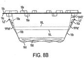
- the side wall spacing "SWS” between the nesting cups tapers outwardly in a direction toward the cups' top perimeters with the fine pill powder material "PPM” migrating upwardly through this space.
- the enlarging side wall spacing “SWS” creates enough open area so as to allow the leading edge "LE” of the powdered pill material "PPM” to continuously cascade back down into the cup during the crushing operation such that the powder pill material "PPM” never reaches the cup open top perimeter.
Landscapes
- Health & Medical Sciences (AREA)
- Life Sciences & Earth Sciences (AREA)
- Animal Behavior & Ethology (AREA)
- General Health & Medical Sciences (AREA)
- Public Health (AREA)
- Veterinary Medicine (AREA)
- Crushing And Pulverization Processes (AREA)
- Crushing And Grinding (AREA)
Description
- The present invention relates to pill crushing systems, and more particularly relates to a pill chip guard which acts to inhibit pill chips from escaping the pill crushing chamber during the pill crushing operation. In another aspect, the invention relates to nestable cups having improved pill crushing features and interfacing dimensions which inhibit migration of the powdered pill material from reaching the top perimeters of the cups.
- The grinding or crushing of pills into powder form may be necessary when, for example, the person has trouble swallowing whole pills due to throat problems. This is a common need in nursing homes and hospitals. While the very first pill crushing device was most likely the mortar and pestle (which is still used today), more technologically advanced pill crushing devices have been developed over the years (manually or electrically driven) which have various designs that offer advantages over the mortar and pestle, such as making the pill crushing operation quicker, easier and safer (e.g., by preventing cross-contamination between different Rx pills ground in succession), for example.
- Some pill crushing devices utilize a pair of disposable cups which may be nested together with the pill located therebetween. As one cup is rotated relative to the other cup, the pill is ground into a powder. The top cup is removed, leaving the powered pill inside the bottom cup. An additive such as juice or applesauce, for example, may be added to the cup and mixed with the powder to form a liquid or slurry which the patient may more easily swallow. An example of such a nested cup pill crushing device may be seen in commonly owned U.S. Patent Publication No.
US 2012/0160946 . While the device of the '946 publication provides advances over the prior art, there remains a possibility that some pill chips may unintentionally escape from between the cups during the crushing operation. It would furthermore be desirable to improve the crushing of the pills into a finer powder to ensure uniform mixing with the liquid additive and ease of swallowing. It would be yet furthermore desirable to provide nesting cups having differing geometries which interface in a manner inhibiting the migration of the fine powder from reaching the top perimeters and spilling out from between the nesting cups. - The present invention is defined by the appended claims. In one aspect, the present invention addresses the above concern of pill chips escaping from between the cups by providing a chip guard positioned to physically block pill chips from exiting between the nested cups during the pill crushing operation. In another aspect, the present invention provides improved nested cup designs which enhance distribution of the pill material between the facing surfaces of the cups during the crushing operation, yet also inhibit the migration of the fine powder from reaching the top open perimeters of the nesting cups. Forcing the pill material as it is being crushed to spread out between a larger surface area increases the amount of pill material subjected to the frictional grinding forces of the nested cups and thereby forms a finer powder than achieved by prior art nested cup designs. Furthermore, including interfacing cup geometries which inhibit migration of the fine powder to the open cup perimeters prevents the loss of pill material from between the open edges of the cups.
- In an embodiment, the present invention provides a pill crushing machine having a bottom cup holder positioned in a main housing and a top cup holder positioned on the inside of a lid hinged to the main housing. A pair of nestable cups are provided for removable placement in the pill crushing machine. The bottom cup is placed upon the bottom cup holder with the pills to be crushed placed inside the bottom cup. The top cup is nested inside the bottom cup with the pills located between the nested bottom and top cups and the lid is moved to the closed position. The machine is activated causing the bottom cup to rise up against and then rotate relative to the stationary top cup. The resultant forces and friction between the bottom and top cups cause the pills located therebetween to be crushed and ground into a powder. The lid is then opened whereupon the top cup is separated from the bottom cup wherein the pill powder is located. A liquid food additive such as juice, applesauce, pudding or the like may be mixed with the powder to form a slurry and given to the patient in a now more easily swallowed form. While described as having a rotating bottom cup and stationary top cup, it is envision that a machine can operate in an inverse relation wherein the top cup rotates and the bottom cup is stationary.
- In the preferred embodiment, the pill crushing machine biases the nested cups toward one another. As the pills undergo the crushing operation, they begin to crack and pulverize into smaller and smaller particles that migrate radially outwardly along the facing surfaces of the cups and, depending on the amount of pill material to be crushed, potentially also up the facing side walls of the cups toward the open top perimeters thereof. In the nested condition, a small gap may exist between the open top perimeters of the bottom and top cups. This creates an area wherethrough pill particles may escape from between the cups. This is undesirable in that any portion of the pills being crushed that do not remain in the cup are lost and the prescribed dose is thereby being unknowingly reduced which could potentially result in adverse health effects on the patient.
- The present invention provides a pill crushing machine with a physical barrier at the location of the nested cups perimeter gap which acts as a "chip guard" to inhibit the escape of pill particles through this gap. In a preferred embodiment, the chip guard is in the form of a ring which is movable between an active guard position and a retracted cup access position allowing easy access to the nested cups into and out of the machine. In the active guard position, the ring wall encircles and lies in close proximity to the gap between the nested cups top perimeters, thereby forming a physical barrier to pill particles which may otherwise escape from between the cups at this gap.
- In yet a further example, the present disclosure provides a pair of nestable cups for a pill crushing machine wherein the bottom cup and top cup have different side wall angles to promote improved pill crushing and inhibit migration of the powdered pill material from reaching the open gap between the cup top perimeters. The respective cup dimensions are selected so as to cause more pronounced migration of the pill particles in a radially outward direction along the facing cup walls. Radial and even migration of the pill particles between the cups is desirable in that the more cup surface area that is actively grinding against the pill particles, the more pill particles will be subject to continuous grinding which results in a finer (smaller) resultant particle size. The finer the resultant powder, the better the powder will mix with the liquid food additive which will be easier to swallow for the patient than a mixture having larger pill particles therein. Furthermore, since the interfacing geometries of the nested cup side walls are such as to inhibit the fine powder from reaching the open top perimeters of the cups, the full amount of finely powdered pill material stays between the cups, and within the bottom cup.
- The above-mentioned and other features and advantages of this invention, and the manner of attaining them, will become apparent and be better understood by reference to the following description of the invention in conjunction with the accompanying drawing, wherein:
-
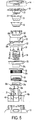
FIG. 1 is a perspective view of the main housing body; -
FIG. 2 is a perspective view of the underside of the lid; -
FIG. 3A is a perspective view to an embodiment of the pill crushing machine without the main body housing; -
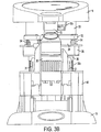
FIG. 3B is a front elevational view thereof; -
FIG. 3C is a side elevational view thereof; -
FIG. 3D is a top plan view thereof; -
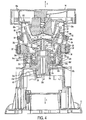
FIG. 4 is a cross-sectional view thereof as taken generally along the line 4-4 ofFIG. 3D ; -
FIG. 5 is an exploded, elevational view thereof; -
FIGS. 6A-6D are views of the top cup; -
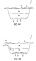
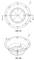
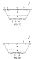
FIGS. 7A-7D are views of the bottom cup; -
FIGS. 8A and8B are side elevational views of the top and bottom cups in their nested condition at the beginning of the pill crushing operation and near the end of the pill crushing operation, respectively; -
FIGS. 9A and9B are enlarged, upper and lower end perspective views, respectively, of the rotator base element,; -
FIGS. 10A and10B are enlarged, upper and lower end perspective views, respectively, of the second base element; -
FIG. 11 is a perspective view of the first axial translation element; -
FIG. 12 is a perspective view of the second axial translation element; -
FIG. 13 is a perspective view of the bottom cup holder; -
FIG. 14 is a perspective view of the second axial translation element; and -
FIG. 15 is an enlarged, fragmented, perspective view of a prong element. - Referring now to the drawing, there is seen in the figures a pill crushing machine designated generally by the
reference numeral 10 having amain housing body 12 andlid 14 which is hinge connected tohousing body 12 viahinge elements Figs. 1 and2 ). While thehousing body 12 seen inFig. 1 is not shown in the remaining figures for the sake of clarity, it is understood that it would extend betweenbase 13 and lid 14 (seeFigs. 3A-5 ). - As seen in
Figures 5 ,6A-6D ,7A-7D , and8A and8B , a pair ofnestable cups machine 10 which are preferably single use and formed of a suitable plastic. In a preferred embodiment shown,bottom cup 16 andtop cup 18 have different dimensions, with top cup 18 (which nests insidebottom cup 16 with pills "P" to be crushed deposited therebetween as seen inFig. 8A ) being overall generally smaller and havingside walls line 18L) which are straight in the direction fromlower wall segment 18b toupper perimeter flange 18c (seen best in the cross-section ofFig. 6D and8A and8B ).Upper wall segment 18a extends at an angle A1 of about 100° with respect toperimeter flange 18c, andlower wall segment 18b extending at an angle A2 of about 170° with respect toupper wall segment 18a. Rather than being straight,upper wall segment 16a ofbottom cup 16 includes having an outwardly curved surface having a radius of about 1.380mm and alower wall segment 16b (which meetsupper wall segment 18a atline 18L) having an inwardly curved surface having a radius of about 1.662mm. The inwardly curvedlower wall segment 16b interfaces closely with top cuplower segment wall 18b to promote fine grinding of the pill particles therebetween while the outwardly curved surface of bottom cupupper wall segment 16a interfaces with the sharper angled (i.e., more vertically inclined that the lower wall segment) straightupper wall segment 18a oftop cup 18 so as to create a large enough space to inhibit pill powder migration as explained further below. Thecup bottom walls fluted sections 16d' and 18d', respectively. Topcup perimeter flange 18c includes a plurality of annularly spaced, upwardly-facing (in a direction away frombottom wall 18d)protrusions 18e, and bottomcup perimeter flange 16c includes a plurality of annularly spaced, downwardly-facing (in a direction towardbottom wall 16d)protrusions 16e, the purpose of which is described below. -
Lid 14 includes atop cup holder 20 having a geometry complimentary to the geometry of the respective inside surfaces of thetop cup 18 to be removably placed thereon which thus forms a mating fit between the two when thetop cup 18 is removably mounted onto thetop cup holder 20. In a further preferred embodiment, a spring loadedplunger 21 may be provided at approximately the center oftop cup holder 20 which biases thetop cup 18 against thebottom cup 16 when the lid is closed. To prevent rotation oftop cup 18 during the pill crushing operation,top cup protrusions 18e may be aligned and engaged with complementary spaced,respective recesses 20a formed about the perimeter of top cup holder 20 (seeFig. 2 ). -
Bottom cup 16 may be removably positioned within complementary shapedbottom cup holder 22. To ensure thatbottom cup 16 will rotate together withbottom cup holder 22 during the pill crushing operation,bottom cup protrusions 16e may align with and be engaged with complementary spacedrespective recesses 22a formed about the perimeter ofbottom cup holder 22. - Bottom cup holder 22 (
Figs. 3-5 and13 ) includes abottom wall 22a,side wall 22b andtop perimeter edge 22c having a plurality of annularly spacedrecesses 22d which may align with and engageprotrusions 16e ofbottom cup 16 when placed therein.Bottom cup holder 22 fits within the complementary shapedcenter recess 24a of rotator base element 24 (see alsoFigs. 9A and9B ).Rotator base element 24 includes alower wall segment 24b which is radially spaced from acenter stem 24c having a plurality of annularly spacedvanes 24d extending radially outwardly therefrom (seeFig. 9B ).Bottom cup holder 22 includes a plurality of annularly spacedrib elements 22e which may align with and engage a like plurality of annularly spacedopenings 24e formed along thelip 24f and extending partly down the side wall 24g thereof (seeFig. 9A ). As such,bottom cup holder 22 is rotationally fixed torotator base element 24. -
Rotator base element 24 may be rotationally fixed to asecond base element 26 viavanes 24d aligning with and fitting within respectivewalled slots 26b which radially extend fromcenter aperture 26a (seeFigs. 4 ,9B and10A ).Second base element 26 includes a lowerannular wall segment 26c defining acenter bore 26d (seeFig. 10B ). A third base element 36 (seeFigs. 4 ,5 and12 ) includes acenter stem portion 36c which telescopes into center bore 26d ofsecond base element 26. As seen best inFig. 12 ,third base element 36 further includes aring element 36a which lies concentrically radially outwardly ofcenter stem portion 36c which forms anannular channel 36d therebetween. Withcenter stem portion 36c inserted intocenter bore 26d,annular wall segment 26c resides withinannular channel 36d (seeFig. 4 ). - Third base element is seen to further include a
shoulder portion 36b and stemportion 36e having a center bore 36g into which the output shaft of a drive motor (not shown) positioned there beneath may extend.Shoulder portion 36b is further seen to taper in a spiral fashion from aminimum width portion 36b' to amaximum width portion 36b" which forms astep 36b'" for reasons explained below. - A first
axial translation element 30 havinginternal threads 30a and externalsplined surface 30c (seeFigs. 4 ,5 and11 ) is fixed tosecond base element 26, e.g., via screws passed throughholes 30b which align withrespective holes 26f (see alsoFig. 10B ). A secondaxial translation element 34 is provided havingthreads 34a on the outer wall surface thereof and terminating in aledge portion 34b (Fig. 14 ). Thelower surface 34c is seated againstshoulder portion 36b of third base element 36 (Fig. 12 ) withledge portion 34b abutting step 36b"'. Secondaxial translation element 34 resides within firstaxial translation element 30 withthreads 30a engaging threads 34a (seeFig. 4 ). - Third base
element stem portion 36e extends into a center bore 40a of ahousing mount 40 withstem clips 36f (Fig. 12 ) engaging and fixingthird base element 36 to mount 40.Shoulder portion 36b is thus seated uponledge 40b ofhousing mount 40. - A chip guard 50 (
Figs. 4 and5 ) is provided which encircles the nesting cups 16, 18 withinmachine 10. InFig. 4 , cups 16,18 are not shown for the sake of clarity, but would reside in the space "S" betweentop cup holder 20 and bottom cup holder. The juncture of the cup perimeters wherein gap "G" is formed (Fig. 8 ) would reside in area indicated by reference arrow SG inFig. 4 . With chipguard wall segment 50a located radially outwardly of space SG, any pill fragments "F" which could otherwise escape through this area are physically blocked by the chip guard. - In a preferred embodiment,
chip guard 50 has a length extending from top cupholder base wall 20a to a position along rotator base elementouter side wall 24e. Aring element 52 is provided which attaches tochip guard 50 viaclips 50b integrally formed in thechip guard 50. One or more spring loadedplunger elements 54connect ring 50 tosecond base element 26 atholes 26'. As such, spring loadedplunger elements 54 act tobias ring 52 and hence alsochip guard 50 toward and against topcup holder base 20a. If desired, one ormore notches 50c may be provided adjacent thetop edge 50d which provide open access to the nested cups. In an alternate embodiment,plunger elements 54 may be electronically controlled whereby they may be signaled to retract when desired which acts to pullring 52 andchip guard 50 down (toward housing base 13). The retracted position ofchip guard 50 would provide access to the cup sitting inbottom cup holder 22. - In yet another embodiment,
chip guard 50 may be fixed to and move together withlid 14 such that whenlid 14 is opened,chip guard 50 is lifted away frombottom cup holder 22. Likewise, whenlid 14 is closed in preparation for pill crushing operation,guard 50 is lowered into its physical blocking position adjacent gap G. - To crush one or more pills,
bottom cup 16 is placed inbottom cup holder 22. Pills "P" are placed insidebottom cup 16 and atop cup 18 is placed (nested) insidebottom cup 16 with the pills P located therebetween (Fig. 8 ).Lid 14 is closed and latched at 15 (Figs. 3A-3D ). The motor (not shown) is activated which rotatesthird base element 36 as described above. Referring toFig 12 , rotation ofthird base element 36 in a clockwise direction "CW" causesstep 36b" to push againstledge portion 34b which causes rotation of secondaxial translation element 34 in the same direction. Firstaxial translation element 30 is prevented from rotating with secondaxial translation element 34 due to one ormore prongs 31 which extend fromledge 40b ofhousing mount 40. - As seen best in
Fig. 14 , eachprong 31 includes a radiallyinward extension 31a which terminates in asplined face 31b.Splined face 31b meshes with thesplined surface 30c of firstaxial translation element 30 and, since the splines extend in a longitudinal direction (parallel to housing axis X-X), firstaxial translation element 30 is prevented from rotating whilesplined face 31b is in meshing engagement withsplined surface 30a. However, since firstaxial translation element 30 is threadedly engaged to secondaxial translation element 34 as explained above, firstaxial translation element 30 will ride along the threads in an upward, axial direction towardlid 14. And sincebottom cup holder 22 is rotationally fixed tosecond base element 26, which in turn is rotationally fixed torotator base element 24, which in turn is rotationally fixed tobottom cup holder 22, they too will all rotate together withbottom cup holder 22 while translating in the same upward, axial direction. This axial translation pressesbottom cup 16 up against top cup 18 (which itself is biased towardbottom cup 16 by spring loadedplunger 21 as described above). -
Spring 56 extends betweenrotator base element 24 andsecond base element 26 to provide additional biasing force ofbottom cup holder 24 in the upward direction towardlid 14. This upward, linear force may act to first crack pills P located between the nesting cups. Once splinedsurface 30a is clear ofsplined face 31b, firstaxial translation element 30 is free to rotate together with second axialtranslational element 34. With bottom cup holder interconnected with firstaxial translation element 30, it too will rotate and causebottom cup 16 to rotate since they are rotationally fixed together. - As discussed above,
top cup 18 remains rotationally fixed via engagement ofprotrusions 18e withrecesses 20a inlid 14. As such,bottom cup 16 rotates against and with respect totop cup 18 which provides a crushing and grinding action upon the pills P located therebetween. As seen inFigs. 8A and8B , while the crushed pill particles are allowed to migrate in a radially outward direction, and potentially also up between theside walls Fig. 8A ) are physically blocked from escaping through gap G bychip guard 50 in the manner explained above. Of course as the pills are being ground into ever smaller particles, the cups begin to move closer together due to the bias forces discussed above.Fig. 8B illustrates the cups very close together at a point near or at the end of the pill crushing operation. The side wall spacing "SWS" between the nesting cups tapers outwardly in a direction toward the cups' top perimeters with the fine pill powder material "PPM" migrating upwardly through this space. The enlarging side wall spacing "SWS" creates enough open area so as to allow the leading edge "LE" of the powdered pill material "PPM" to continuously cascade back down into the cup during the crushing operation such that the powder pill material "PPM" never reaches the cup open top perimeter.
Claims (5)
- Pill crushing apparatus (10) for use with first and second nestable cups (16, 18), said apparatus comprising:a) a first cup holder (22) configured to removably hold said first nestable cup (16);b) a cup holder fixture consisting of a first axial translation element (30), a second base element (26) and a rotator base element (24), said cup holder fixture axially aligned with said first cup holder (22);c) a second axial translation element (34) axially aligned with said cup holder fixture opposite said first cup holder (22), said second axial translation element (34) operably engaged with said cup holder fixture such that said cup holder fixture and said second axial translation element (34) may translate linearly with respect to each other;d) a second cup holder (20) axially alignable with said first cup holder (22) opposite said cup holder fixture and configured to releasably engage said second nestable cup (18); ande) a chip guard (50) adapted to encircle said first and second cup holders (22, 20);whereby, upon rotation of said second axial translation element (34), said cup holder fixture translates said first cup holder (22) into engagement with said second cup holder (20) thereby causing said cup holder fixture to rotate with respect to said second cup holder (20) and thereby imparting a grinding force against pills held between said first and second nestable cups (16, 18), and wherein said chip guard (50) prevents ground pill material from escaping said first and second nestable cups (16, 18).
- The apparatus of claim 1 and further comprising a spring (56) between said cup holder fixture and said first cup holder, said spring (56) becoming gradually compressed as said cup holder fixture moves toward and engages said first cup holder (22).
- The apparatus of claim 1 and further comprising a drive shaft connected to and operable to rotate said second axial translation element (34).
- The apparatus of claim 1 and further comprising a housing (12) and a lid (14) movable between an open and closed position with respect to said housing (12), said second cup holder (20) located on said lid (14) and axially aligned with said first cup holder (22) when said lid (14) is in said closed position.
- The apparatus of claim 1 wherein:a) said first axial translation element (30) of said cup holder fixture further includes a first set of threads (30a);b) said second axial translating element (34) further includes a second set of threads (34a) which mesh with said first set of threads (30a) on said first axial translation element (30) such that said cup holder fixture and said second axial translating element (34) may translate linearly with respect to each other.
Applications Claiming Priority (2)
| Application Number | Priority Date | Filing Date | Title |
|---|---|---|---|
| US201261676281P | 2012-07-26 | 2012-07-26 | |
| PCT/US2013/052298 WO2014018870A1 (en) | 2012-07-26 | 2013-07-26 | Pill crushing system |
Publications (3)
| Publication Number | Publication Date |
|---|---|
| EP2877287A1 EP2877287A1 (en) | 2015-06-03 |
| EP2877287A4 EP2877287A4 (en) | 2016-07-20 |
| EP2877287B1 true EP2877287B1 (en) | 2018-09-05 |
Family
ID=49997855
Family Applications (2)
| Application Number | Title | Priority Date | Filing Date |
|---|---|---|---|
| EP13822505.7A Not-in-force EP2877287B1 (en) | 2012-07-26 | 2013-07-26 | Pill crushing system |
| EP15765807.1A Withdrawn EP3119523A4 (en) | 2012-07-26 | 2015-03-20 | Pill crushing cups with rotational locking lugs |
Family Applications After (1)
| Application Number | Title | Priority Date | Filing Date |
|---|---|---|---|
| EP15765807.1A Withdrawn EP3119523A4 (en) | 2012-07-26 | 2015-03-20 | Pill crushing cups with rotational locking lugs |
Country Status (9)
| Country | Link |
|---|---|
| US (1) | US9717651B2 (en) |
| EP (2) | EP2877287B1 (en) |
| AU (2) | AU2013295573B2 (en) |
| CA (2) | CA2879144C (en) |
| DK (1) | DK2877287T3 (en) |
| ES (1) | ES2690324T3 (en) |
| MY (1) | MY171492A (en) |
| SG (1) | SG11201500292SA (en) |
| WO (2) | WO2014018870A1 (en) |
Families Citing this family (22)
| Publication number | Priority date | Publication date | Assignee | Title |
|---|---|---|---|---|
| EP2877287B1 (en) * | 2012-07-26 | 2018-09-05 | First Wave Products Group, LLC | Pill crushing system |
| CN104994826B (en) * | 2012-12-20 | 2019-08-23 | 金泰裕 | Pharmaceutical method and pharmaceutical device |
| US10548813B2 (en) | 2015-04-22 | 2020-02-04 | Ann Evans | Pill crushing device for pulverizing pills and minimizing transfer loss of pulverized pills |
| US9827166B2 (en) * | 2015-04-22 | 2017-11-28 | Ann Evans | Pill crushing device for pulverizing pills and minimizing transfer loss of pulverized pills |
| US10993880B2 (en) | 2015-04-22 | 2021-05-04 | Ann Evans | Pill crusher |
| US10577159B2 (en) | 2017-04-07 | 2020-03-03 | Berry Plastics Corporation | Drink cup lid |
| CN108785092A (en) * | 2017-04-26 | 2018-11-13 | 杨松 | Pressing device and its application method |
| WO2019032564A1 (en) | 2017-08-07 | 2019-02-14 | Berry Global, Inc. | Method and apparatus for thermoforming an article |
| US10864141B2 (en) * | 2017-10-06 | 2020-12-15 | Pharmatools, LLC | Combination pill cutter and crusher pliers |
| CN108652979B (en) * | 2018-03-02 | 2020-10-16 | 马春雨 | Particle medicine grinding equipment for pediatrics |
| USD907997S1 (en) | 2018-08-10 | 2021-01-19 | Berry Global, Inc. | Drink cup lid |
| US11891488B2 (en) | 2019-02-06 | 2024-02-06 | Berry Global, Inc. | Polypropylene sheets and articles |
| EP4656356A1 (en) | 2019-02-06 | 2025-12-03 | Berry Global, Inc. | Process of forming polymeric material |
| USD911168S1 (en) | 2019-03-05 | 2021-02-23 | Berry Global, Inc. | Drink cup lid |
| US11591140B2 (en) | 2019-08-15 | 2023-02-28 | Berry Global, Inc. | Drink cup lid |
| WO2021046522A1 (en) * | 2019-09-06 | 2021-03-11 | First Wave Products Group, Llc | Pill cup assembly |
| US11490765B2 (en) * | 2020-01-02 | 2022-11-08 | E-Link Plastic & Metal Industrial Co., Ltd. | Medicine grinder |
| CA3188065A1 (en) | 2020-08-05 | 2022-02-10 | Jonathan EICKHOFF | Polypropylene sheets and articles |
| CN112426364B (en) * | 2020-12-01 | 2021-08-24 | 吉林大学 | A cancer patient injecting exudate with chemotherapeutic drugs |
| US12441523B2 (en) | 2021-07-06 | 2025-10-14 | Berry Global, Inc. | Drink cup lid |
| USD1061244S1 (en) | 2021-07-09 | 2025-02-11 | Berry Global, Inc. | Drink cup lid |
| US20250152474A1 (en) * | 2023-11-11 | 2025-05-15 | Serrano Medical Solutions Inc. | Pill-crushing machine with pre-biased crusher |
Family Cites Families (14)
| Publication number | Priority date | Publication date | Assignee | Title |
|---|---|---|---|---|
| US2886253A (en) * | 1957-09-16 | 1959-05-12 | Pfizer & Co C | Tablet pulverizing and dispensing device |
| US4575014A (en) | 1984-06-27 | 1986-03-11 | Rexnord Inc. | Vertical shaft impact crusher rings |
| US4756484A (en) | 1986-09-22 | 1988-07-12 | Nordberg, Inc. | Vertical shaft impact crusher with interchangeable crusher ring segments |
| US5118021A (en) | 1991-05-10 | 1992-06-02 | American Medical Industries | Pill splitter |
| US5553793A (en) * | 1993-12-15 | 1996-09-10 | Lake Medical Products, Inc. | Combination pill crushing and dispensing cup |
| JP2001219084A (en) * | 2000-02-10 | 2001-08-14 | Hiroyuki Ueno | Tablet crusher |
| JP2003053208A (en) * | 2001-08-22 | 2003-02-25 | Yuyama Manufacturing Co Ltd | Tablet crusher |
| CA2447753A1 (en) | 2003-11-03 | 2005-05-03 | Occupational Health And Safety Agency For Healthcare | Pill crushers |
| US7543770B2 (en) * | 2004-08-20 | 2009-06-09 | The Research Foundation Of State University Of New York | Automated pill crusher |
| US7472856B2 (en) | 2006-02-08 | 2009-01-06 | Shears W Allan | Pill crusher |
| US7735763B2 (en) * | 2007-09-17 | 2010-06-15 | First Wave Products Group, Llc | Pill crusher with pill holder verification and safety features |
| EP2396115A4 (en) * | 2009-02-10 | 2015-09-02 | First Wave Products Group Llc | DEVICE AND METHOD FOR MILLING PILLS |
| WO2011103616A1 (en) | 2010-02-25 | 2011-09-01 | Manrex Pty. Ltd | Improvements relating to tablet crushing |
| EP2877287B1 (en) * | 2012-07-26 | 2018-09-05 | First Wave Products Group, LLC | Pill crushing system |
-
2013
- 2013-07-26 EP EP13822505.7A patent/EP2877287B1/en not_active Not-in-force
- 2013-07-26 AU AU2013295573A patent/AU2013295573B2/en not_active Ceased
- 2013-07-26 CA CA2879144A patent/CA2879144C/en not_active Expired - Fee Related
- 2013-07-26 SG SG11201500292SA patent/SG11201500292SA/en unknown
- 2013-07-26 WO PCT/US2013/052298 patent/WO2014018870A1/en not_active Ceased
- 2013-07-26 ES ES13822505.7T patent/ES2690324T3/en active Active
- 2013-07-26 MY MYPI2015000189A patent/MY171492A/en unknown
- 2013-07-26 DK DK13822505.7T patent/DK2877287T3/en active
-
2014
- 2014-03-21 US US14/222,050 patent/US9717651B2/en not_active Expired - Fee Related
-
2015
- 2015-03-20 CA CA2945005A patent/CA2945005A1/en not_active Abandoned
- 2015-03-20 EP EP15765807.1A patent/EP3119523A4/en not_active Withdrawn
- 2015-03-20 AU AU2015231029A patent/AU2015231029A1/en not_active Abandoned
- 2015-03-20 WO PCT/US2015/021745 patent/WO2015143316A1/en not_active Ceased
Non-Patent Citations (1)
| Title |
|---|
| None * |
Also Published As
| Publication number | Publication date |
|---|---|
| US9717651B2 (en) | 2017-08-01 |
| CA2945005A1 (en) | 2015-09-24 |
| DK2877287T3 (en) | 2018-12-17 |
| US20140217221A1 (en) | 2014-08-07 |
| SG11201500292SA (en) | 2015-02-27 |
| AU2013295573A1 (en) | 2015-02-05 |
| WO2015143316A1 (en) | 2015-09-24 |
| ES2690324T3 (en) | 2018-11-20 |
| EP3119523A1 (en) | 2017-01-25 |
| MY171492A (en) | 2019-10-15 |
| EP3119523A4 (en) | 2018-03-28 |
| EP2877287A4 (en) | 2016-07-20 |
| WO2014018870A1 (en) | 2014-01-30 |
| AU2015231029A1 (en) | 2016-10-20 |
| EP2877287A1 (en) | 2015-06-03 |
| CA2879144A1 (en) | 2014-01-30 |
| AU2013295573B2 (en) | 2018-09-13 |
| CA2879144C (en) | 2020-09-22 |
Similar Documents
| Publication | Publication Date | Title |
|---|---|---|
| CA2879144C (en) | Pill crushing system | |
| CN105979998B (en) | Method and apparatus for preparing suspensions and solutions from drugs in pill or tablet form | |
| EP3155936B1 (en) | Juice extraction module for juicer | |
| EP2767201A1 (en) | A grinding unit, a cartridge for the grinding unit and use of same for grinding coffee beans | |
| US11490765B2 (en) | Medicine grinder | |
| EP2596730A1 (en) | Grinder facilitating adjustment of grinding fineness | |
| CN107072419A (en) | Citrus lid for agitator | |
| US20220218152A1 (en) | Herb grinder and associated method | |
| AU2010213874B2 (en) | Pill crusher device and method | |
| CN105682805A (en) | Pre-comminuting device for a ball mill or agitator ball mill, and ball mill with pre-comminuting device | |
| CN116096276A (en) | Grinding device | |
| US9615695B2 (en) | Food processor having removable feed tube | |
| CN106363682A (en) | Food preparation device having at least one rotary spiral cutting tool | |
| KR102661108B1 (en) | Separation screw and juice apparatus using the same | |
| CN206688858U (en) | A kind of device for grinding medical tablets | |
| CN105395108B (en) | It is suitable for handling the food preparation device of ripe food and/or frangible food | |
| KR101286887B1 (en) | Juice Extracting Apparatus that Manually Operated | |
| US9635982B2 (en) | Food processor having removable feed tube | |
| JP2016052641A (en) | Mortar and beverage production equipment | |
| US20210069065A1 (en) | Pill cup assembly | |
| KR102151171B1 (en) | Bean size regulation apparatus of grinder | |
| CN113440030B (en) | Circulating grinding structure and food processing appliance | |
| KR102466894B1 (en) | juicer for onion | |
| CN113843031B (en) | Food crushing device | |
| JP2001224513A (en) | Tea leaf crusher |
Legal Events
| Date | Code | Title | Description |
|---|---|---|---|
| PUAI | Public reference made under article 153(3) epc to a published international application that has entered the european phase |
Free format text: ORIGINAL CODE: 0009012 |
|
| 17P | Request for examination filed |
Effective date: 20150116 |
|
| AK | Designated contracting states |
Kind code of ref document: A1 Designated state(s): AL AT BE BG CH CY CZ DE DK EE ES FI FR GB GR HR HU IE IS IT LI LT LU LV MC MK MT NL NO PL PT RO RS SE SI SK SM TR |
|
| AX | Request for extension of the european patent |
Extension state: BA ME |
|
| DAX | Request for extension of the european patent (deleted) | ||
| RIC1 | Information provided on ipc code assigned before grant |
Ipc: A61J 3/02 20060101ALI20160216BHEP Ipc: B02C 19/00 20060101AFI20160216BHEP |
|
| RA4 | Supplementary search report drawn up and despatched (corrected) |
Effective date: 20160622 |
|
| RIC1 | Information provided on ipc code assigned before grant |
Ipc: A61J 3/02 20060101ALI20160616BHEP Ipc: B02C 19/00 20060101AFI20160616BHEP |
|
| STAA | Information on the status of an ep patent application or granted ep patent |
Free format text: STATUS: REQUEST FOR EXAMINATION WAS MADE |
|
| GRAP | Despatch of communication of intention to grant a patent |
Free format text: ORIGINAL CODE: EPIDOSNIGR1 |
|
| STAA | Information on the status of an ep patent application or granted ep patent |
Free format text: STATUS: GRANT OF PATENT IS INTENDED |
|
| INTG | Intention to grant announced |
Effective date: 20180315 |
|
| GRAS | Grant fee paid |
Free format text: ORIGINAL CODE: EPIDOSNIGR3 |
|
| GRAA | (expected) grant |
Free format text: ORIGINAL CODE: 0009210 |
|
| STAA | Information on the status of an ep patent application or granted ep patent |
Free format text: STATUS: THE PATENT HAS BEEN GRANTED |
|
| AK | Designated contracting states |
Kind code of ref document: B1 Designated state(s): AL AT BE BG CH CY CZ DE DK EE ES FI FR GB GR HR HU IE IS IT LI LT LU LV MC MK MT NL NO PL PT RO RS SE SI SK SM TR |
|
| REG | Reference to a national code |
Ref country code: GB Ref legal event code: FG4D |
|
| REG | Reference to a national code |
Ref country code: CH Ref legal event code: EP |
|
| REG | Reference to a national code |
Ref country code: AT Ref legal event code: REF Ref document number: 1037213 Country of ref document: AT Kind code of ref document: T Effective date: 20180915 |
|
| REG | Reference to a national code |
Ref country code: IE Ref legal event code: FG4D |
|
| REG | Reference to a national code |
Ref country code: DE Ref legal event code: R096 Ref document number: 602013043286 Country of ref document: DE |
|
| REG | Reference to a national code |
Ref country code: ES Ref legal event code: FG2A Ref document number: 2690324 Country of ref document: ES Kind code of ref document: T3 Effective date: 20181120 |
|
| REG | Reference to a national code |
Ref country code: NL Ref legal event code: FP |
|
| REG | Reference to a national code |
Ref country code: SE Ref legal event code: TRGR |
|
| REG | Reference to a national code |
Ref country code: DK Ref legal event code: T3 Effective date: 20181210 |
|
| REG | Reference to a national code |
Ref country code: LT Ref legal event code: MG4D |
|
| PG25 | Lapsed in a contracting state [announced via postgrant information from national office to epo] |
Ref country code: BG Free format text: LAPSE BECAUSE OF FAILURE TO SUBMIT A TRANSLATION OF THE DESCRIPTION OR TO PAY THE FEE WITHIN THE PRESCRIBED TIME-LIMIT Effective date: 20181205 Ref country code: GR Free format text: LAPSE BECAUSE OF FAILURE TO SUBMIT A TRANSLATION OF THE DESCRIPTION OR TO PAY THE FEE WITHIN THE PRESCRIBED TIME-LIMIT Effective date: 20181206 Ref country code: LT Free format text: LAPSE BECAUSE OF FAILURE TO SUBMIT A TRANSLATION OF THE DESCRIPTION OR TO PAY THE FEE WITHIN THE PRESCRIBED TIME-LIMIT Effective date: 20180905 Ref country code: RS Free format text: LAPSE BECAUSE OF FAILURE TO SUBMIT A TRANSLATION OF THE DESCRIPTION OR TO PAY THE FEE WITHIN THE PRESCRIBED TIME-LIMIT Effective date: 20180905 |
|
| REG | Reference to a national code |
Ref country code: NO Ref legal event code: T2 Effective date: 20180905 |
|
| REG | Reference to a national code |
Ref country code: AT Ref legal event code: MK05 Ref document number: 1037213 Country of ref document: AT Kind code of ref document: T Effective date: 20180905 |
|
| PG25 | Lapsed in a contracting state [announced via postgrant information from national office to epo] |
Ref country code: HR Free format text: LAPSE BECAUSE OF FAILURE TO SUBMIT A TRANSLATION OF THE DESCRIPTION OR TO PAY THE FEE WITHIN THE PRESCRIBED TIME-LIMIT Effective date: 20180905 Ref country code: AL Free format text: LAPSE BECAUSE OF FAILURE TO SUBMIT A TRANSLATION OF THE DESCRIPTION OR TO PAY THE FEE WITHIN THE PRESCRIBED TIME-LIMIT Effective date: 20180905 Ref country code: LV Free format text: LAPSE BECAUSE OF FAILURE TO SUBMIT A TRANSLATION OF THE DESCRIPTION OR TO PAY THE FEE WITHIN THE PRESCRIBED TIME-LIMIT Effective date: 20180905 |
|
| PG25 | Lapsed in a contracting state [announced via postgrant information from national office to epo] |
Ref country code: RO Free format text: LAPSE BECAUSE OF FAILURE TO SUBMIT A TRANSLATION OF THE DESCRIPTION OR TO PAY THE FEE WITHIN THE PRESCRIBED TIME-LIMIT Effective date: 20180905 Ref country code: EE Free format text: LAPSE BECAUSE OF FAILURE TO SUBMIT A TRANSLATION OF THE DESCRIPTION OR TO PAY THE FEE WITHIN THE PRESCRIBED TIME-LIMIT Effective date: 20180905 Ref country code: AT Free format text: LAPSE BECAUSE OF FAILURE TO SUBMIT A TRANSLATION OF THE DESCRIPTION OR TO PAY THE FEE WITHIN THE PRESCRIBED TIME-LIMIT Effective date: 20180905 Ref country code: IS Free format text: LAPSE BECAUSE OF FAILURE TO SUBMIT A TRANSLATION OF THE DESCRIPTION OR TO PAY THE FEE WITHIN THE PRESCRIBED TIME-LIMIT Effective date: 20190105 Ref country code: PL Free format text: LAPSE BECAUSE OF FAILURE TO SUBMIT A TRANSLATION OF THE DESCRIPTION OR TO PAY THE FEE WITHIN THE PRESCRIBED TIME-LIMIT Effective date: 20180905 Ref country code: CZ Free format text: LAPSE BECAUSE OF FAILURE TO SUBMIT A TRANSLATION OF THE DESCRIPTION OR TO PAY THE FEE WITHIN THE PRESCRIBED TIME-LIMIT Effective date: 20180905 |
|
| PG25 | Lapsed in a contracting state [announced via postgrant information from national office to epo] |
Ref country code: SK Free format text: LAPSE BECAUSE OF FAILURE TO SUBMIT A TRANSLATION OF THE DESCRIPTION OR TO PAY THE FEE WITHIN THE PRESCRIBED TIME-LIMIT Effective date: 20180905 Ref country code: PT Free format text: LAPSE BECAUSE OF FAILURE TO SUBMIT A TRANSLATION OF THE DESCRIPTION OR TO PAY THE FEE WITHIN THE PRESCRIBED TIME-LIMIT Effective date: 20190105 Ref country code: SM Free format text: LAPSE BECAUSE OF FAILURE TO SUBMIT A TRANSLATION OF THE DESCRIPTION OR TO PAY THE FEE WITHIN THE PRESCRIBED TIME-LIMIT Effective date: 20180905 |
|
| REG | Reference to a national code |
Ref country code: DE Ref legal event code: R097 Ref document number: 602013043286 Country of ref document: DE |
|
| PLBE | No opposition filed within time limit |
Free format text: ORIGINAL CODE: 0009261 |
|
| STAA | Information on the status of an ep patent application or granted ep patent |
Free format text: STATUS: NO OPPOSITION FILED WITHIN TIME LIMIT |
|
| 26N | No opposition filed |
Effective date: 20190606 |
|
| PG25 | Lapsed in a contracting state [announced via postgrant information from national office to epo] |
Ref country code: SI Free format text: LAPSE BECAUSE OF FAILURE TO SUBMIT A TRANSLATION OF THE DESCRIPTION OR TO PAY THE FEE WITHIN THE PRESCRIBED TIME-LIMIT Effective date: 20180905 |
|
| PGFP | Annual fee paid to national office [announced via postgrant information from national office to epo] |
Ref country code: NL Payment date: 20190726 Year of fee payment: 7 |
|
| PGFP | Annual fee paid to national office [announced via postgrant information from national office to epo] |
Ref country code: FI Payment date: 20190729 Year of fee payment: 7 Ref country code: ES Payment date: 20190801 Year of fee payment: 7 Ref country code: SE Payment date: 20190729 Year of fee payment: 7 Ref country code: FR Payment date: 20190726 Year of fee payment: 7 Ref country code: IT Payment date: 20190726 Year of fee payment: 7 Ref country code: DK Payment date: 20190729 Year of fee payment: 7 Ref country code: NO Payment date: 20190729 Year of fee payment: 7 Ref country code: DE Payment date: 20190729 Year of fee payment: 7 |
|
| PGFP | Annual fee paid to national office [announced via postgrant information from national office to epo] |
Ref country code: BE Payment date: 20190729 Year of fee payment: 7 |
|
| PGFP | Annual fee paid to national office [announced via postgrant information from national office to epo] |
Ref country code: GB Payment date: 20190729 Year of fee payment: 7 |
|
| PGFP | Annual fee paid to national office [announced via postgrant information from national office to epo] |
Ref country code: CH Payment date: 20190801 Year of fee payment: 7 |
|
| PG25 | Lapsed in a contracting state [announced via postgrant information from national office to epo] |
Ref country code: MC Free format text: LAPSE BECAUSE OF FAILURE TO SUBMIT A TRANSLATION OF THE DESCRIPTION OR TO PAY THE FEE WITHIN THE PRESCRIBED TIME-LIMIT Effective date: 20180905 |
|
| PG25 | Lapsed in a contracting state [announced via postgrant information from national office to epo] |
Ref country code: TR Free format text: LAPSE BECAUSE OF FAILURE TO SUBMIT A TRANSLATION OF THE DESCRIPTION OR TO PAY THE FEE WITHIN THE PRESCRIBED TIME-LIMIT Effective date: 20180905 |
|
| PG25 | Lapsed in a contracting state [announced via postgrant information from national office to epo] |
Ref country code: LU Free format text: LAPSE BECAUSE OF NON-PAYMENT OF DUE FEES Effective date: 20190726 |
|
| PG25 | Lapsed in a contracting state [announced via postgrant information from national office to epo] |
Ref country code: IE Free format text: LAPSE BECAUSE OF NON-PAYMENT OF DUE FEES Effective date: 20190726 |
|
| REG | Reference to a national code |
Ref country code: DE Ref legal event code: R119 Ref document number: 602013043286 Country of ref document: DE |
|
| REG | Reference to a national code |
Ref country code: FI Ref legal event code: MAE |
|
| REG | Reference to a national code |
Ref country code: CH Ref legal event code: PL |
|
| REG | Reference to a national code |
Ref country code: DK Ref legal event code: EBP Effective date: 20200731 Ref country code: NO Ref legal event code: MMEP |
|
| REG | Reference to a national code |
Ref country code: SE Ref legal event code: EUG |
|
| REG | Reference to a national code |
Ref country code: NL Ref legal event code: MM Effective date: 20200801 |
|
| GBPC | Gb: european patent ceased through non-payment of renewal fee |
Effective date: 20200726 |
|
| REG | Reference to a national code |
Ref country code: BE Ref legal event code: MM Effective date: 20200731 |
|
| PG25 | Lapsed in a contracting state [announced via postgrant information from national office to epo] |
Ref country code: CH Free format text: LAPSE BECAUSE OF NON-PAYMENT OF DUE FEES Effective date: 20200731 Ref country code: LI Free format text: LAPSE BECAUSE OF NON-PAYMENT OF DUE FEES Effective date: 20200731 Ref country code: GB Free format text: LAPSE BECAUSE OF NON-PAYMENT OF DUE FEES Effective date: 20200726 Ref country code: FI Free format text: LAPSE BECAUSE OF NON-PAYMENT OF DUE FEES Effective date: 20200726 Ref country code: FR Free format text: LAPSE BECAUSE OF NON-PAYMENT OF DUE FEES Effective date: 20200731 Ref country code: NL Free format text: LAPSE BECAUSE OF NON-PAYMENT OF DUE FEES Effective date: 20200801 Ref country code: NO Free format text: LAPSE BECAUSE OF NON-PAYMENT OF DUE FEES Effective date: 20200731 |
|
| PG25 | Lapsed in a contracting state [announced via postgrant information from national office to epo] |
Ref country code: DE Free format text: LAPSE BECAUSE OF NON-PAYMENT OF DUE FEES Effective date: 20210202 Ref country code: BE Free format text: LAPSE BECAUSE OF NON-PAYMENT OF DUE FEES Effective date: 20200731 Ref country code: CY Free format text: LAPSE BECAUSE OF FAILURE TO SUBMIT A TRANSLATION OF THE DESCRIPTION OR TO PAY THE FEE WITHIN THE PRESCRIBED TIME-LIMIT Effective date: 20180905 Ref country code: SE Free format text: LAPSE BECAUSE OF NON-PAYMENT OF DUE FEES Effective date: 20200727 |
|
| PG25 | Lapsed in a contracting state [announced via postgrant information from national office to epo] |
Ref country code: HU Free format text: LAPSE BECAUSE OF FAILURE TO SUBMIT A TRANSLATION OF THE DESCRIPTION OR TO PAY THE FEE WITHIN THE PRESCRIBED TIME-LIMIT; INVALID AB INITIO Effective date: 20130726 Ref country code: MT Free format text: LAPSE BECAUSE OF FAILURE TO SUBMIT A TRANSLATION OF THE DESCRIPTION OR TO PAY THE FEE WITHIN THE PRESCRIBED TIME-LIMIT Effective date: 20180905 |
|
| PG25 | Lapsed in a contracting state [announced via postgrant information from national office to epo] |
Ref country code: DK Free format text: LAPSE BECAUSE OF NON-PAYMENT OF DUE FEES Effective date: 20200731 |
|
| PG25 | Lapsed in a contracting state [announced via postgrant information from national office to epo] |
Ref country code: IT Free format text: LAPSE BECAUSE OF NON-PAYMENT OF DUE FEES Effective date: 20200726 |
|
| REG | Reference to a national code |
Ref country code: ES Ref legal event code: FD2A Effective date: 20211230 |
|
| PG25 | Lapsed in a contracting state [announced via postgrant information from national office to epo] |
Ref country code: ES Free format text: LAPSE BECAUSE OF NON-PAYMENT OF DUE FEES Effective date: 20200727 |
|
| PG25 | Lapsed in a contracting state [announced via postgrant information from national office to epo] |
Ref country code: MK Free format text: LAPSE BECAUSE OF FAILURE TO SUBMIT A TRANSLATION OF THE DESCRIPTION OR TO PAY THE FEE WITHIN THE PRESCRIBED TIME-LIMIT Effective date: 20180905 |