EP2877091B1 - Device and method for sensing the size of a load on a biological system - Google Patents
Device and method for sensing the size of a load on a biological system Download PDFInfo
- Publication number
- EP2877091B1 EP2877091B1 EP13745002.9A EP13745002A EP2877091B1 EP 2877091 B1 EP2877091 B1 EP 2877091B1 EP 13745002 A EP13745002 A EP 13745002A EP 2877091 B1 EP2877091 B1 EP 2877091B1
- Authority
- EP
- European Patent Office
- Prior art keywords
- measuring
- shoe sole
- force
- substrate layer
- expansion
- Prior art date
- Legal status (The legal status is an assumption and is not a legal conclusion. Google has not performed a legal analysis and makes no representation as to the accuracy of the status listed.)
- Active
Links
- 238000000034 method Methods 0.000 title claims description 17
- 238000005452 bending Methods 0.000 claims description 16
- 239000000463 material Substances 0.000 claims description 11
- 230000005489 elastic deformation Effects 0.000 claims description 6
- 210000000988 bone and bone Anatomy 0.000 claims description 5
- 230000003068 static effect Effects 0.000 claims description 4
- 229910001220 stainless steel Inorganic materials 0.000 claims description 3
- 239000010935 stainless steel Substances 0.000 claims description 3
- 239000000758 substrate Substances 0.000 claims 20
- 239000010410 layer Substances 0.000 description 93
- 210000002683 foot Anatomy 0.000 description 40
- 238000005259 measurement Methods 0.000 description 16
- 238000011156 evaluation Methods 0.000 description 12
- 210000001255 hallux Anatomy 0.000 description 11
- 230000033001 locomotion Effects 0.000 description 10
- 210000004744 fore-foot Anatomy 0.000 description 9
- 230000001133 acceleration Effects 0.000 description 6
- 230000005021 gait Effects 0.000 description 6
- 230000005484 gravity Effects 0.000 description 6
- 238000002360 preparation method Methods 0.000 description 6
- 230000008859 change Effects 0.000 description 5
- 210000003414 extremity Anatomy 0.000 description 5
- 230000000399 orthopedic effect Effects 0.000 description 5
- 239000005038 ethylene vinyl acetate Substances 0.000 description 4
- 229920001200 poly(ethylene-vinyl acetate) Polymers 0.000 description 4
- 239000011241 protective layer Substances 0.000 description 4
- 230000009471 action Effects 0.000 description 3
- 230000005540 biological transmission Effects 0.000 description 3
- 238000010276 construction Methods 0.000 description 3
- 238000011161 development Methods 0.000 description 3
- 230000018109 developmental process Effects 0.000 description 3
- 230000000694 effects Effects 0.000 description 3
- 238000012545 processing Methods 0.000 description 3
- 230000001681 protective effect Effects 0.000 description 3
- 230000000284 resting effect Effects 0.000 description 3
- 241001465754 Metazoa Species 0.000 description 2
- DQXBYHZEEUGOBF-UHFFFAOYSA-N but-3-enoic acid;ethene Chemical compound C=C.OC(=O)CC=C DQXBYHZEEUGOBF-UHFFFAOYSA-N 0.000 description 2
- 238000001514 detection method Methods 0.000 description 2
- 230000004069 differentiation Effects 0.000 description 2
- 238000005516 engineering process Methods 0.000 description 2
- 230000037230 mobility Effects 0.000 description 2
- 238000012986 modification Methods 0.000 description 2
- 230000004048 modification Effects 0.000 description 2
- 229920001296 polysiloxane Polymers 0.000 description 2
- 230000002829 reductive effect Effects 0.000 description 2
- 238000012552 review Methods 0.000 description 2
- 238000005096 rolling process Methods 0.000 description 2
- 210000003371 toe Anatomy 0.000 description 2
- 206010000234 Abortion spontaneous Diseases 0.000 description 1
- 206010017076 Fracture Diseases 0.000 description 1
- 241000124008 Mammalia Species 0.000 description 1
- 208000013201 Stress fracture Diseases 0.000 description 1
- 238000007792 addition Methods 0.000 description 1
- 210000003423 ankle Anatomy 0.000 description 1
- 230000003466 anti-cipated effect Effects 0.000 description 1
- 210000000544 articulatio talocruralis Anatomy 0.000 description 1
- 230000008901 benefit Effects 0.000 description 1
- 238000009530 blood pressure measurement Methods 0.000 description 1
- 230000001419 dependent effect Effects 0.000 description 1
- 238000013461 design Methods 0.000 description 1
- 206010012601 diabetes mellitus Diseases 0.000 description 1
- 201000010099 disease Diseases 0.000 description 1
- 208000037265 diseases, disorders, signs and symptoms Diseases 0.000 description 1
- 239000013013 elastic material Substances 0.000 description 1
- 238000007667 floating Methods 0.000 description 1
- 210000000548 hind-foot Anatomy 0.000 description 1
- 208000014674 injury Diseases 0.000 description 1
- 210000001503 joint Anatomy 0.000 description 1
- 230000005923 long-lasting effect Effects 0.000 description 1
- 210000001872 metatarsal bone Anatomy 0.000 description 1
- 208000015994 miscarriage Diseases 0.000 description 1
- 238000012544 monitoring process Methods 0.000 description 1
- 210000002346 musculoskeletal system Anatomy 0.000 description 1
- 230000036961 partial effect Effects 0.000 description 1
- 230000002028 premature Effects 0.000 description 1
- 230000009467 reduction Effects 0.000 description 1
- 208000000995 spontaneous abortion Diseases 0.000 description 1
- 239000003351 stiffener Substances 0.000 description 1
- 230000009897 systematic effect Effects 0.000 description 1
- 230000009885 systemic effect Effects 0.000 description 1
- 238000012360 testing method Methods 0.000 description 1
- 238000012549 training Methods 0.000 description 1
- 238000012546 transfer Methods 0.000 description 1
- 230000008733 trauma Effects 0.000 description 1
- 230000001960 triggered effect Effects 0.000 description 1
Images


Classifications
-
- A—HUMAN NECESSITIES
- A61—MEDICAL OR VETERINARY SCIENCE; HYGIENE
- A61B—DIAGNOSIS; SURGERY; IDENTIFICATION
- A61B5/00—Measuring for diagnostic purposes; Identification of persons
- A61B5/103—Detecting, measuring or recording devices for testing the shape, pattern, colour, size or movement of the body or parts thereof, for diagnostic purposes
- A61B5/1036—Measuring load distribution, e.g. podologic studies
-
- A—HUMAN NECESSITIES
- A61—MEDICAL OR VETERINARY SCIENCE; HYGIENE
- A61B—DIAGNOSIS; SURGERY; IDENTIFICATION
- A61B5/00—Measuring for diagnostic purposes; Identification of persons
- A61B5/68—Arrangements of detecting, measuring or recording means, e.g. sensors, in relation to patient
- A61B5/6801—Arrangements of detecting, measuring or recording means, e.g. sensors, in relation to patient specially adapted to be attached to or worn on the body surface
- A61B5/6802—Sensor mounted on worn items
- A61B5/6804—Garments; Clothes
- A61B5/6807—Footwear
-
- A—HUMAN NECESSITIES
- A61—MEDICAL OR VETERINARY SCIENCE; HYGIENE
- A61B—DIAGNOSIS; SURGERY; IDENTIFICATION
- A61B2562/00—Details of sensors; Constructional details of sensor housings or probes; Accessories for sensors
- A61B2562/16—Details of sensor housings or probes; Details of structural supports for sensors
- A61B2562/164—Details of sensor housings or probes; Details of structural supports for sensors the sensor is mounted in or on a conformable substrate or carrier
Definitions
- the invention is directed to a device for detecting at least one mechanical load variable occurring on a part of a biological system, the device comprising an elastically deformable carrier layer arranged load-bearingly on the part, in particular a limb, a joint or a bone, of the biological system in which at least one measuring device forming a measuring point or a measuring field is arranged, which has at least one force and / or strain sensor.
- the invention is further directed to a method for detecting at least one of a part, in particular a limb, a joint or a bone, a biological system occurring mechanical load size, wherein on the part of an elastically deformable support layer is arranged load-absorbing and wherein the load size at the elastically deformable carrier layer by means of at least one measuring device mounted there, in particular by means of a force and / or strain sensor is determined.
- the invention is directed to a use of a device mentioned above for carrying out a method mentioned.
- a biological system is understood in the context of the present invention to mean every living being that is separated from the environment by its body.
- the term biological system is not limited to living beings, but may also include dead animals. Parts of such a biological system are then in particular limbs or limbs or joints or bones of the body of a living being.
- this biological system acts on such a "part" of the biological system or acts on a load variable.
- the detection of such load variables is essentially in the present invention.
- the detection of a load size is not limited to living organisms or living biological systems. But a very important focus is on the human, or the human body as a biological system. But also animals and especially mammals fall under the term "biological system”.
- Shoes protect and support the feet from a mechanical point of view, in that they dampen, for example, occurring pressures, guiding and supporting the foot.
- a generic device for data acquisition and - evaluation in shoes or shoe inserts is from the DE 102 01 134 A1 known.
- This device discloses a measuring system with which also torsional loads as well as bending, shear, torsional and longitudinal stresses on the feet can be detected.
- the basis for this is one equipped with measuring fields Shoe insole, whereby the desired information in the measuring fields with piezoelectric effects or elements, but also with strain gauges, detected and the respective generated voltage signals can be processed.
- this document does not disclose the exact arrangement and positioning of the actual transducers.
- a generic device also reveal the DE 198 10 182 C1 and the EP 1 709 904 A2 ,
- a based on pressure measuring sensors device is also from the DE 10 2010 049 154 A1 known.
- This document discloses a sole with a sensor for use in a shoe, wherein the mechanical pressure distribution on the human foot sole is measured with sensors and electronics.
- the sensors and the electronics are arranged on a circuit board. As sensors capacitive pressure sensors are used.
- the performance of a multiaxial stress analysis of dynamic and static loads occurring on a shoe sole arranged in or on a shoe when the shoe is worn is to be enabled without the need for a floor reaction force.
- the at least one measuring point or the at least one measuring field has at least two measuring means, in particular force and / or strain sensors, arranged opposite one another on the carrier layer.
- this object is achieved in a method of the type described in more detail by the fact that the mechanical load size by means of at least two, at a measuring point or a measuring field to each other on the carrier layer oppositely arranged measuring means, in particular force and / or strain sensors detected.
- the device comprises at least one elastically deformable carrier layer, in particular measuring sole, with at least one measuring point or one measuring field.
- the measuring point has on opposite sides - preferably at the top and bottom - each having a measuring means.
- Such an arrangement of measuring means at a plurality of different measuring points or measuring fields of the carrier layer, in particular shoe sole, makes it possible to obtain an overview of the load on the carrier layer, in particular the shoe sole, and thus of the part of the biological system resting on the carrier layer or adjacent thereto the shoe sole resting foot, and to perform a multi-axial stress analysis.
- the invention therefore provides that the part is a human foot.
- the carrier layer is part of a shoe sole or forms such, or that the carrier layer is part of a shoe sole or forms such, wherein the shoe sole is designed as a removable insole, which the invention also provides.
- the invention provides that at least one of the measuring means is a multiaxial stress and / or strain state, in particular an elastic deformation, the carrier layer, in particular shoe sole, detecting force and / or strain sensor.
- At least one of the force and / or strain sensors is a static and / or dynamic multiaxial stress and / or strain state of the carrier layer, in particular shoe sole, detecting force and / or strain sensor.
- the force and / or strain sensors is a static and / or dynamic multiaxial stress and / or strain state of the carrier layer, in particular shoe sole, detecting force and / or strain sensor.
- stress conditions detecting force and / or strain sensors can be provided in an advantageous manner insole systems for shoes, with which dynamic multi-axial stresses or strains of the shoe sole during human movement in the shoe can be detected.
- At least one of the force and / or strain sensors may be a bending moment and / or torsion moments and / or bending stresses and / or torsional stresses of the carrier layer, in particular shoe sole, detecting force and / or strain sensor.
- the respectively at least two measuring means, in particular force and / or strain sensors, arranged opposite each other at a measuring point or measuring field have a multiaxial stress and / or strain state, in particular an elastic deformation, the carrier layer, in particular shoe sole, Detecting force and / or strain sensors.
- the combination of at least two at a measuring point or in a measuring field opposite to each other arranged force and / or strain sensors with their training as a multiaxial stress and / or strain state and detecting force and / or strain sensors can be the desired dynamic or static Multi-axial stress analysis and multi-axial strains of the support layer, in particular shoe sole, during the movement of each examined part of the biological system, in particular the human foot in a shoe, detect.
- the invention further provides that a measuring point or a measuring field has a carrier layer, in particular a shoe sole, with a first surface and the second surface, wherein each measuring point or per measuring field respectively on the first surface and the second surface the support layer, in particular shoe sole, at least one a multiaxial stress and / or strain state of the support layer, in particular shoe sole, detecting force and / or strain sensor is arranged.
- a particularly expedient embodiment of the shoe sole is that the shoe sole is designed as a removable insole.
- the shoe sole or the carrier layer is preferably made of a material, in particular stainless steel, which is arranged, for example, in a shoe sole or, as such, subjected to a natural load by a human foot only in its elastic region, in particular deformed.
- the at least one force and / or strain sensor can / can be designed as strain gauges (DMS), which the invention also provides. It may be expedient if the strain gauge (DMS) and / or the strain gauges (DMS) in each case as DMS rosette, in particular as a 90 ° -DMS rosette, is formed / are.
- DMS strain gauge
- DMS strain gauge
- DMS strain gauge
- DMS strain gauges
- Such a special electrical connection of each of the measuring points makes it easy to carry out a comparison and a combinatorial processing of the values respectively measured, that is, of the respectively triggered electrical signals, which are respectively measured and measured on an upper side and at the lower side of the same measuring point or the same measuring field.
- the device distinguishes itself from the previously known devices and methods in that due to the arrangement of at least one measuring device per measuring point or measuring field, for example on the top and bottom of a shoe sole or measuring sole, and due to the special interconnection (Wheatstone bridge) of the measuring means a unique assignment of the load shape is possible (eg a clear distinction between bending and tensile load).
- the at least one force and / or strain sensor is positively connected to the shoe sole and / or the carrier layer, wherein preferably at least one force and / or strain sensor or force and / or or strain sensors and the carrier layer are covered by a highly elastic material layer.
- curvatures of the carrier layer occurring during walking can be measured well with the DMS. Furthermore, it can be determined by comparing the measured values on an upper side and an underside of the measuring point or of the measuring field whether there is a bending of the shoe sole, and into which Direction the sole is bent at each load condition.
- DMS strain gauge
- the shoe sole has a plurality of measuring points, each with a strain gauge (DMS) arranged at the top and bottom or on opposite sides of the carrier layer, it is also possible to determine whether and where the carrier layer is twisted.
- DMS strain gauge
- Strain gauges are inexpensive to obtain and allow a precise measurement of the stresses occurring on the opposite surfaces of the carrier layer or on the top and bottom of the measuring points and measuring fields defined on the sole.
- the part of the biological system to be examined for example the shoe size, the sole size, the sole shape, but also the load and / or the desired resolution of the measurement results is influenced.
- the number and the arrangement according to the invention of the measuring means does not hinder the movement of the part, in particular of the foot, which is advantageous.
- a 90 ° DMS rosette also referred to as a "T" rosette
- a DMS rosette has the task of determining the changes in length at the measuring point, but detects a biaxial, multiaxial, state of stress.
- 90 ° rosettes are preferably used when the main strain directions or principal stress directions due to previous considerations are known. If the main strain directions or principal stress directions are not known, 3-element rosettes are preferably used, such as 45 °, right angle or 60 ° delta rosettes.
- planar or crossed rosettes can be used for the measurement.
- Planar rosette designs cover a larger area than crossed rosette versions.
- oppositely disposed 90 ° DMS rosettes have a Wheatstone bridge circuit.
- this circuit technology also enables a clear demarcation of a portion of a biological system, for example one resting on the sole, associated with each measuring field in the individual regions Foot, occurring, multi-axial sole load and stress.
- the carrier layer or the shoe sole is elastic and has defined known mechanical material properties, such as a known modulus of elasticity.
- the curvatures of the examined part, for example the footbed, which occur during a movement of the foot, are carried out by the carrier layer or the shoe sole.
- the bending and torsional stresses are detected by means of the respective force and / or strain sensors, for example by means of 90 ° -DMS rosettes.
- the voltage occurring at the measuring points and in the measuring fields can then be calculated from the measured values recorded, i. a multi-axial stress analysis is performed.
- the device comprises a shoe having a base or outsole and arranged on the base or outsole shoe sole having the measuring points or the measuring fields comprises.
- the invention then provides in particular that the shoe sole has a first elastomeric protective layer and a first measuring layer arranged thereunder on a first side of the carrier layer and a second measuring layer arranged on a second side of the carrier layer and a second elastomeric protective layer covering the second measuring layer in a protective manner.
- the shoe sole is located on the base or outsole in the shoe.
- the base or outsole has an outer base or running profile. The contact of the shoe to a pad is made by the base or outsole.
- Shoe sole and base or outsole together form the sole area of the shoe.
- each carrier layer expediently has an upper, first elastomeric protective layer, a first measuring layer arranged thereunder on a first (upper) side of the carrier layer, a second measuring layer arranged on a second (lower) side of the carrier layer and one second measuring layer protective lower, second elastomeric protective layer on.
- the Measuring layers have at defined positions, the measuring points, measuring means.
- the measuring means are arranged so that they face each other at a measuring point or a measuring field.
- the force and / or strain sensors and the associated measurement and supply lines can be covered with silicone and the carrier layer with flexible ethylene vinyl acetate (EVA; 25-35 SH).
- EVA flexible ethylene vinyl acetate
- the at least one measuring means is associated with an evaluation in which by means of force and / or strain sensors generated electrical voltage signals and stored in the evaluation unit material characteristics, in particular elastic moduli and resistive moments , a Troxiaer the stress and / or strain state at the respective measuring point or the respective measuring field is determined.
- the measuring means in particular the force and / or strain sensors, via measuring and / or supply lines with an evaluation, a memory device, a device for power supply and / or a data readout be electrically connected.
- the measuring means of the device according to the invention are therefore optionally electrically connected via the measuring and supply lines with an evaluation device, a memory device, a device for power supply and a data read-out unit.
- the Evaluation device preferably on the special electrical interconnection in the form of one or more Wheatstone bridges, the latter can also be arranged in a separate circuit for the evaluation device or interconnection device / can.
- the measured data can be read out via Bluetooth.
- Another possibility is, for example, an infrared interface. This readout option - Bluetooth or infrared interface - is advantageously used for example in a monitoring of athletes during a competition.
- the method according to the invention can be characterized in that a multiaxial stress and / or strain state, in particular elastic deformation, of the carrier layer is detected as a mechanical load variable.
- a multiaxial stress and / or strain state, in particular elastic deformation, of the carrier layer is detected as a mechanical load variable.
- the at least one mechanical load variable is detected and / or determined by means of one of the devices according to one of claims 1 to 12.
- the inventive method is applicable to the human body as a biological system.
- the mechanical load size can be detected on a human foot.
- a carrier layer designed as a shoe sole is arranged on the part, in particular the human foot.
- the biological system in the sense of the system theory of Luhmann
- the biological system is the human body and the part of the biological system, at which an occurring mechanical load size is to be determined, a human foot 1.
- the carrier layer 24 provided according to the invention is consequently part of a shoe sole 3 or forms a shoe sole 3.
- FIG. 1 is a foot model with shoe 2 during a gait cycle in the swing preparation shown.
- the foot 1 is surrounded by the shoe 2.
- the foot 1 rests on the shoe sole 3.
- the load on the foot 1 is absorbed by the forefoot 4 in this foot position.
- the rear part of the foot 1 is at an angle 5 relative to a base 6, on which the shoe 2 rests, raised.
- shear forces occur parallel to the marked x - axis.
- cause of the shear forces is the rolling of the forefoot 4 and thus the shoe 2 on the base 6.
- F g + a the weight and acceleration force of the body center of gravity
- F b the floor reaction force, two of the forces occurring during the rolling process of the forefoot 4 on the base 6. Both forces are drawn on a line of action.
- Both F g + a and F b have components parallel to the x- and to a perpendicular y-axis.
- the shoe sole 3 has at least one measuring point or a measuring field generally designated 7.
- the shoe sole 3 six measuring fields 701, 702, 703, 704, 705, 706, of which in the FIG. 1 the measuring fields 701, 703 and 706 are recognizable.
- Each of the measurement fields 701-706 includes one above and one, respectively measuring means 801, 802, 803, 804, 805, 806, 807, 808, 809, 810, 811, 812 arranged below a carrier layer 24, of which in the FIG. 1 the measuring means 801 and 802 assigned to the measuring field 701, the measuring means 805 and 806 assigned to the measuring field 703 and the measuring means 809 and 810 assigned to the measuring field 706 can be seen.
- each of the measuring means 801-812 forms a measuring point.
- the individual measuring means 801 to 812 are each designed as a force and / or strain sensor 8 in the form of a strain gauge (DMS) or in the form of a plurality of cooperating or interconnected strain gauges (DMS).
- the task of the DMS is to provide values for a length change or a multiaxial stress state in the respective measuring field.
- the multiaxial stresses or strains occurring at the shoe sole 3 per measuring point 801 or per measuring field 7 on the shoe sole 3 are determined as the load size to be determined.
- the measuring means 801-812 are arranged in pairs opposite one another on the upper and lower sides of a carrier layer 24
- a measuring device 90 ° -DMS rosettes, which are also referred to as "T" rosettes, use.
- T time difference measuring device
- the use of this rosette type is advantageous when the principal strain or principal stress directions of the shoe sole 3 are known on the basis of previous considerations. If the principal strain or principal strain directions are unknown, strain gauges are preferably used in the form of 3-element rosettes, whether 45 ° rosette, right angle rosette or 60 ° delta rosette.
- the electrical connection in each case to two force and / or strain sensors 8, preferably strain gage rosettes, lying opposite each other on one of the measuring fields 701 -706 is effected in each case by means of a Wheatstone bridge circuit, preferably an electrical half-bridge.
- a Wheatstone bridge circuit preferably an electrical half-bridge.
- the measurement fields 701 and 702 are arranged in the forefoot region, the measurement fields 703 and 704 in the metatarsal region and the measurement fields 705 and 706 in the hindfoot region, the measurement fields 701, 703 and 705 being arranged medially and the measurement fields 702, 704 and 706 being arranged laterally.
- the use of a Wheatstone bridge is advantageous because even small changes in the force and / or strain sensors 8 and thus in the shoe sole 3 can be measured.
- the materials and the material properties of the shoe sole 3 and in particular the material properties of a carrier layer 24 are selected so that the shoe sole 3 and / or the carrier layer 24 are deformed by the occurring loads and load sizes exclusively in the elastic region.
- known material parameters such as modulus of elasticity and moments of resistance
- the desired load variables, stresses, and multiaxial stress states of the shoe sole 3 and the moments acting on the measuring fields 701 to 706 can then be determined by means of the measuring means and a suitable associated evaluation unit. It is the identification of characteristic and relevant sizes of feet and shoe stress, multi-axial viewing of foot and shoe stress, and stress analysis with no effect of floor reaction force possible.
- FIG. 2 shows the foot model with shoe 2 according to FIG. 1 with now integrated illustrated mechanical foot model 12 during the gait cycle of the swing preparation.
- the mechanical foot model 12 represents a lever model.
- Significant additions compared to FIG. 1 is the representation of the bearings 13 and 14 of the mechanical foot model
- the bearing 13 is designed as a mechanical floating bearing which absorbs normal forces and, according to its arrangement, is associated with the big toe end joint.
- the bearing 14 is designed as a mechanical bearing and assigned according to its arrangement to the great toe joint. In this illustration, the weight and acceleration force of the body center of gravity F g + a and the floor reaction force F b on the forefoot 4 attack. Both forces are on a line of action.
- FIG. 4 further shows the mechanical foot model during the gait cycle of the swing preparation, unlike the FIG. 3 a shoe sole 3 is located, at which the acceleration force of the body center of gravity F g + a on the upper side 9 of the shoe sole 3 acts. Likewise, the reaction force on the big toe joint F b_MTP and the reaction force on the big toe joint F b-IP on the bottom 10 of the shoe sole 3 attack.
- FIG. 5 shows the mechanical foot model with the shoe sole 3 now without torque at the upper ankle to a state according to FIG. 4 immediately following time of the gait cycle of the swing preparation.
- the point of application of the reaction force on the great toe joint F b_MTP is offset by the distance b (to the right).
- mechanical foot model can be inventively Distributed Multiaxial stress states that occur on a human foot during a walking motion in a shoe 2 and detect and determine by means of the device according to the invention as to be determined load size (s).
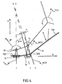
- FIG. 6 schematically shows an enlarged view of an embodiment of a sole structure.
- a sole region of a shoe 2 denoted overall by 17 comprises a base or outsole 18 and a shoe sole 3 arranged in the form of an insole on the inside of the shoe.
- the base or outsole 18 has an outer base or running profile 23 which is not shown in greater detail stability while running.
- the device according to the invention is designed such that a measuring point or a measuring field 7 of the carrier layer 24, in particular the shoe sole 3, a first surface or first side and a second surface or second side, wherein each measuring point or per measuring field respectively on the first surface or side and on the second surface or side of the support layer 24, in particular shoe sole 3, arranged opposite each other at least one multi-axial stress and / or strain state of the support layer 24, in particular Shoe sole 3, detecting force and / or strain sensor 8 is arranged.
- the shoe sole 3 has a three-layered construction.
- the middle layer is the carrier layer 24.
- On the top side, ie on the first side or the first surface there is a first measuring layer 20 on the carrier layer 24.
- measuring means are arranged at defined positions and on the first side or the first Surface of the support layer 24 positively secured, of which the measuring means 801 and 802 in the FIG. 6 are shown.
- an upper elastomeric layer 19 is applied on the first measuring layer 20.
- the layer 19 is used to protect the measuring means, in the embodiment thus the measuring means 801, 803, 805, 807, 809 arranged on the upper side, as well as the (in the FIGS. 7a and 7b shown) measuring and supply lines 15 of the measuring means.
- a second measuring layer 21 is arranged on the carrier layer 24.
- This second measuring layer 21 has measuring means 802, 804, 806, 808, 810 and 812 which are arranged on the underside and which are frictionally fixed on the second side or the second surface of the carrier layer 24 at likewise defined positions, namely the measuring means arranged directly on the upper side.
- a, now lower, elastomeric layer 22 is applied on the second measuring layer 21, in turn.
- the layer 22 also serves to protect measuring and supply lines 15.
- the region covering the force and / or strain sensors 8 is made of silicone and the area covering the carrier layer 24 is made of a flexible ethylene vinyl acetate (EVA, 25-35 SH).
- EVA flexible ethylene vinyl acetate
- FIGS. 7a and 7b each show schematically a plan view of a shoe sole 3, once from above ( Fig. 7a ) and once from below ( Fig. 7b ).
- the shoe sole 3 is provided with the associated measuring means 801 to 812.
- six 90 ° -DMS rosettes 801, 803, 805, 807, 809 and 811 are arranged in the upper-side first measurement layer 20 of the shoe sole 3.
- the 90 ° -DMS rosettes 801, 803, 805, 807, 809 and 811 are uniquely assigned to one of the measuring fields 701 to 706 in the first measuring layer 20 in each case.
- the 90 ° -DMS rosettes 801, 803, 805, 807, 809 and 811 on the other side of the carrier layer 24 are in each case opposite in the lower second measuring layer 21 of the shoe sole 3, the 90 ° -DMS rosettes 802, 804, 806, 808, 810 and 812 arranged.
- Each pair of the pairwise opposite 90 ° -DMS rosettes 801 to 812 are each electrically metrological by means of a Wheatstone bridge interconnected and interconnected.
- the use of a Wheatstone bridge is advantageous here, as even small changes in the 90 ° -DMS rosettes of the shoe sole 3 can be measured.
- Each Wheatstone bridge has four leads, two sense leads and two supply leads.
- the measuring and supply lines 15 lead to a, in particular electronic, evaluation and / or data read-out unit 16, which reads and / or processing the electrical voltage signals generated by the force and / or strain sensors 8 in the form of 90 ° -DMS rosettes allows.
- this comprises one or more Wheatstone bridge (s).
- the reading or transmission can be wired or wired, but also by means of Bluetooth or infrared interface and transmission can be realized.
- the Ausleseweise by means of Bluetooth is advantageous because it allows, for example, a data transfer with free movement of the subject.
- a power supply to the electronic evaluation and / or data read-out unit 16 is possible, for example, by means of a battery.
- FIG. 8 schematically shows a longitudinal section through the shoe sole 3.
- the section shows in principle the layered structure of the shoe sole 3. Shown are the respective mutually associated 90 ° -DMS rosettes 803 and 804 of the measuring field 702 and the 90 ° -DMS rosettes 811 and 812 of Measuring field 706.
- the carrier layer 24 is sandwiched in the middle. On the upper side, the carrier layer 24 is provided with the first measuring layer 20 and on the underside, the carrier layer 24 is provided with the second measuring layer 21.
- the shoe sole 3 has a total, i. including the 90 ° -DMS rosettes, first measuring layer 20 and second 21 measuring layer and the elastomeric protective and outer layers 19 and 22, a height of about 3 mm at a size of the shoe sole 3 corresponding to the German shoe sizes of 30 to 50.
- the carrier layer 24 consists of a stainless steel layer with a thickness of 0.5 mm, wherein the force and / or strain sensors 8 are applied directly to their metallic surfaces, in particular non-positively.
- FIG. 8 On the right is shown schematically a partial section through the measuring field 702 at the position of the 90 ° -DMS rosettes 803 and 804 with an intermediate portion of the carrier layer 24. This illustration clearly shows the directly opposite arrangement of two 90 ° -DMS rosettes 803 and 804.
- FIG. 8 On the left is further schematically shown a plan view of the 90 ° -DMS rosette 811 with associated measuring and supply lines 15.
- FIG. 9 shows with the device according to the invention averaged strain curves in the longitudinal direction of the shoe sole 3 behind the big toe joint during walking, once with (dashed line) and once without (solid line) shoe change (by means of a sole roller).
- a test person (40 years, 70 kg, with restricted mobility of the great toe) first went to the measurement curves without any shoe changes.
- the data was converted with an analog-to-digital converter (125 Hz, 16 bit, 4 channels), transmitted via Bluetooth to an evaluation unit and recorded using LabView-based software.
- FIG. 9 shows further that the objective of a successful determination of Vorfußbe screwung can be realized by means of the device and the method according to the invention, because a systematic determination of the strains / deformations / stresses, ie the occurring multi-axial stress states, with the inventive shoe sole 3 while walking possible and feasible.
- the device according to the invention and the method according to the invention can be successfully used in a review of orthopedic-technical measures for diabetic shoes.
- the affected foot must be completely relieved using orthopedic aids. Stiffeners of the entire shoe and so-called sole rolls are used.
- the supply controls have hitherto been carried out with pressure measuring soles according to the prior art, which, however, provides only insufficient results, because only normal pressures can be measured therewith.
- the effectiveness of shoe changes significantly better and more targeted to be reviewed because lower multi-axial deformations of the shoe sole 3 mean smaller strains and thus smaller stresses and moments, which are detectable by means of the invention but. In this way, it can be concluded that the foot load is reduced.
- Prostheses replace amputated limbs. They should ensure a good replacement of function at the affected site. In terms of the legs, this means that well-adapted prostheses ensure stability and safety and restore patient mobility.
- a differentiation of tensile loads ( Fig. 10c ) and bending loads ( Fig. 10b ) is possible only on the basis of the top and bottom arrangement of the pressure and / or measuring sensors 8 and S 0 and S 1 on the carrier layer 24. If a bend occurs at the respective measuring point, there is a positive deformation of the sensor S 0 and a negative of the sensor S 1 (FIG. Fig. 10b ). In train, however, both sensors S 0 and S 1 are positively deformed ( Fig. 10c ).
- the carrier layer 24 or the sole 3 has a mirror-symmetrical cross section in the measuring field in the longitudinal and transverse directions. It follows that the positive and negative values determined at bending negative deformations have the same amount but opposite signs.
Description
Die Erfindung richtet sich auf eine Vorrichtung zur Erfassung mindestens einer an einem Teil eines biologischen Systems auftretenden mechanischen Lastgröße, wobei die Vorrichtung eine an dem Teil, insbesondere einer Extremität, einem Gelenk oder einem Knochen, des biologischen Systems lastaufnehmend angeordnete oder anordnenbare, elastisch verformbare Trägerschicht aufweist, an welcher mindestens ein eine Messstelle oder ein Messfeld ausbildendes Messmittel angeordnet ist, das mindestens einen Kraft- und/oder Dehnungssensor aufweist.The invention is directed to a device for detecting at least one mechanical load variable occurring on a part of a biological system, the device comprising an elastically deformable carrier layer arranged load-bearingly on the part, in particular a limb, a joint or a bone, of the biological system in which at least one measuring device forming a measuring point or a measuring field is arranged, which has at least one force and / or strain sensor.
Die Erfindung richtet sich weiterhin auf ein Verfahren zur Erfassung mindestens einer an einem Teil, insbesondere einer Extremität, einem Gelenk oder einem Knochen, eines biologischen Systems auftretenden mechanischen Lastgröße, wobei an dem Teil eine elastisch verformbare Trägerschicht lastaufnehmend angeordnet wird und wobei die Lastgröße an der elastisch verformbaren Trägerschicht mittels mindestens eines dort angebrachten Messmittels, insbesondere mittels eines Kraft- und/oder Dehnungssensors, ermittelt wird.The invention is further directed to a method for detecting at least one of a part, in particular a limb, a joint or a bone, a biological system occurring mechanical load size, wherein on the part of an elastically deformable support layer is arranged load-absorbing and wherein the load size at the elastically deformable carrier layer by means of at least one measuring device mounted there, in particular by means of a force and / or strain sensor is determined.
Schließlich richtet sich die Erfindung auf eine Verwendung einer vorstehend erwähnten Vorrichtung zur Durchführung eines erwähnten Verfahrens.Finally, the invention is directed to a use of a device mentioned above for carrying out a method mentioned.
Unter einem biologischen System wird im Rahmen der vorliegenden Erfindung entsprechend der Systemtheorie nach Luhmann jedes Lebewesen verstanden, das sich durch seinen Körper von der Umwelt abgrenzt. Vereinfacht stellt jeder Körper eines Lebewesens somit ein biologisches System dar. Hierbei beschränkt sich der Begriff biologisches System aber nicht auf lebende Lebewesen, sondern kann auch tote Lebewesen umfassen. Teile eines solchen biologischen Systems sind dann insbesondere Extremitäten oder Gliedmaße oder Gelenke oder Knochen des Körpers eines Lebewesens. Hierbei ist es dann weiterhin so, dass auf dieses biologische System beispielsweise bei einer natürlichen Bewegung des lebenden Lebewesens auf ein solches "Teil" des biologischen Systems Kräfte einwirken oder eine Lastgröße einwirkt. Um die Erfassung derartiger Lastgrößen geht es im Wesentlichen bei der vorliegenden Erfindung. Hierbei ist die Erfassung einer Lastgröße aber nicht auf lebende Lebewesen oder lebende biologische Systeme beschränkt. Eine ganz wesentliche Ausrichtung ist aber die auf den Menschen, beziehungsweise den menschlichen Körper als ein biologisches System. Aber auch Tiere und hier insbesondere Säugetiere fallen unter den Begriff "biologisches System".According to Luhmann's system theory, a biological system is understood in the context of the present invention to mean every living being that is separated from the environment by its body. Everyone puts in a simplified way Body of a living being thus a biological system dar. Here, the term biological system is not limited to living beings, but may also include dead animals. Parts of such a biological system are then in particular limbs or limbs or joints or bones of the body of a living being. In this case, it continues to be the case that, for example in the case of a natural movement of the living organism, this biological system acts on such a "part" of the biological system or acts on a load variable. The detection of such load variables is essentially in the present invention. However, the detection of a load size is not limited to living organisms or living biological systems. But a very important focus is on the human, or the human body as a biological system. But also animals and especially mammals fall under the term "biological system".
Fehlhaltungen und Beschwerden am menschlichen Muskel-Skelett-System treten bei vielen Menschen auf. Damit einhergehende Schmerzen können bei Erwerbstätigen zu einem vorzeitigen Ausscheiden aus dem Erwerbsleben führen.Miscarriage and discomfort in the human musculoskeletal system occur in many people. Associated pain can lead to a premature departure from working life in gainfully employed persons.
Schuhe schützen und unterstützen die Füße in mechanischer Hinsicht, im dem sie beispielsweise auftretende Drücke dämpfen, den Fuß führen und stützen.Shoes protect and support the feet from a mechanical point of view, in that they dampen, for example, occurring pressures, guiding and supporting the foot.
Bestehen Fehlhaltungen und Beschwerden, ist das Wiederherstellen der richtigen Funktionalität oder eine Entlastung der Füße über eine Modifikation der Schuhe und der Sohlen ein entscheidender Faktor in der orthopädischen Versorgungspraxis. Um dies zu gewährleisten, ist die Ermittlung der während des Stehens, Gehens und Laufens in den Schuhen und an den Füßen auftretenden, mehraxialen mechanischen Beanspruchungen und Belastungen von großem Interesse. Dies gilt insbesondere bei einer Überprüfung von orthopädischen Veränderungen an einem Schuh, einer Prothese oder einer Schuhsohle, die eine Verbesserung der Qualität der Bewegung bewirken sollen.If bad posture and discomfort exist, restoring proper functionality or relieving the feet through a modification of the shoes and soles is a crucial factor in orthopedic care practice. To ensure this, is the determination of while standing, walking and running in the Footwear and multi-axial mechanical stresses and strains of great interest. This applies in particular to a review of orthopedic changes to a shoe, a prosthesis or a shoe sole, which are intended to improve the quality of the movement.
In der Praxis der Biomechanik, der Sportwissenschaft, der Schuhindustrie und der Technischen Orthopädie ist es bisher üblich, im Schuh auftretende Belastungen mittels plantarer Druckmessung unter Zurhilfenahme entsprechender Innensohlensysteme zu erfassen und zu ermitteln.In the practice of biomechanics, sports science, the shoe industry and technical orthopedics, it has hitherto been customary to detect and determine stresses occurring in the shoe by means of plantar pressure measurement with the aid of corresponding insole systems.
Mit derartigen Messsystemen können aber nur Kräfte und deren Wirkung analysiert werden, die senkrecht zur Sohle auftreten. Es können also lediglich einaxiale Beanspruchungen festgestellt werden.With such measuring systems but only forces and their effect can be analyzed, which occur perpendicular to the sole. Thus, only uniaxial stresses can be detected.
Die Betrachtung mehraxialer Spannungszustände bei der Schuh- und Fußbeanspruchung sind mit derartigen Vorrichtungen nicht möglich. Entlastende Maßnahmen, zum Beispiel des Vorfußbereichs, welche bei diversen orthopädischen und systemischen Erkrankungen indiziert sind, lassen sich auf diese Weise daher nur unzureichend überprüfen. Das liegt u.a. daran, dass mit diesen Systemen nur Normalkräfte oder deren Veränderung, beispielsweise infolge einer Veränderung des Sohlenaufbaus, gemessen werden können.The consideration of multi-axial stress states in the shoe and foot stress are not possible with such devices. Relief measures, for example, of the forefoot area, which are indicated for various orthopedic and systemic diseases, can therefore only be insufficiently examined in this way. This is u.a. The fact that only normal forces or their change, for example as a result of a change in the sole structure, can be measured with these systems.
Eine gattungsgemäße Vorrichtung zur Messwerterfassung und - auswertung in Schuhen oder Schuheinlagen ist aus der
Eine gattungsgemäße Vorrichtung offenbaren auch die
Eine auf Druckmesssensoren basierende Vorrichtung ist zudem aus der
Der Erfindung liegt die Aufgabe zugrunde, eine gegenüber dem Stand der Technik verbesserte Lösung zu schaffen, die die Durchführung einer mehraxialen Spannungsanalyse von an einer lastaufnehmenden Vorrichtung angreifenden Kräften oder Belastungen, die von einem Teil eines biologischen Systems ausgeübt werden, ermöglicht.It is an object of the present invention to provide an improved solution over the prior art which permits the performance of a multi-axial stress analysis of forces or stresses on a load-bearing device exerted by a portion of a biological system.
Nach einem Aspekt der Erfindung soll insbesondere die Durchführung einer mehraxialen Spannungsanalyse von an einer in oder an einem Schuh angeordneten Schuhsohle beim Tragen des Schuhs auftretenden dynamischen und statischen Belastungen ermöglicht werden, ohne dass hierbei eine Bodenreaktionskraft einwirken muss.According to one aspect of the invention, in particular, the performance of a multiaxial stress analysis of dynamic and static loads occurring on a shoe sole arranged in or on a shoe when the shoe is worn is to be enabled without the need for a floor reaction force.
Bei einer Vorrichtung der eingangs näher bezeichneten Art wird diese Aufgabe erfindungsgemäß dadurch gelöst, dass die mindestens eine Messstelle oder das mindeste eine Messfeld mindestens zwei an der Trägerschicht einander gegenüberliegend angeordnete Messmittel, insbesondere Kraft- und/oder Dehnungssensoren, aufweist.In a device of the type described in more detail, this object is achieved according to the invention in that the at least one measuring point or the at least one measuring field has at least two measuring means, in particular force and / or strain sensors, arranged opposite one another on the carrier layer.
Ebenso wird diese Aufgabe erfindungsgemäß bei einem Verfahren der eingangs näher bezeichneten Art dadurch gelöst, dass die mechanische Lastgröße mittels mindestens zweier, an einer Messstelle oder einem Messfeld einander an der Trägerschicht gegenüberliegend angeordneter Messmittel, insbesondere Kraft- und/oder Dehnungssensoren, erfasst wird.Likewise, this object is achieved in a method of the type described in more detail by the fact that the mechanical load size by means of at least two, at a measuring point or a measuring field to each other on the carrier layer oppositely arranged measuring means, in particular force and / or strain sensors detected.
Schließlich wird diese Aufgabe erfindungsgemäß auch durch die Verwendung einer Vorrichtung nach einem der Ansprüche 1 - 12 zur Durchführung eines Verfahrens nach einem der Ansprüche 13 - 15 gelöst.Finally, this object is also achieved by the use of a device according to one of claims 1 - 12 for carrying out a method according to any one of claims 13 - 15.
Vorteilhafte Weiterbildungen und zweckmäßige Ausgestaltungen der Erfindung sind Gegenstand der jeweiligen abhängigen Ansprüche.Advantageous developments and expedient embodiments of the invention are the subject of the respective dependent claims.
Mit der Erfindung ist es möglich, an einer Messstelle oder in einem Messfeld mehraxiale Spannungen oder Dehnungen der Trägerschicht, insbesondere der Schuhsohle, während einer Bewegung des biologischen Systems und hier des messtechnisch erfassten Teils des biologischen Systems, insbesondere des menschlichen Fußes, zu detektieren. Hierzu umfasst die Vorrichtung wenigstens eine elastisch verformbare Trägerschicht, insbesondere Messsohle, mit wenigstens einer Messstelle oder einem Messfeld. Die Messstelle weist an gegenüberliegenden Seiten - vorzugsweise oben und unten - jeweils ein Messmittel auf. Diese Anordnung der Messmittel ist vorteilhaft, weil sie einen Vergleich und eine kombinatorische Verarbeitung der auf einer Oberseite oder ersten Seite und einer Unterseite oder zweiten Seite derselben Messstelle gemessenen, d.h. erfassten, Werte erlaubt. Eine derartige Anordnung von Messmitteln an mehreren verschiedenen Messstellen oder Messfeldern der Trägerschicht, insbesondere Schuhsohle, ermöglicht es, einen Überblick über die Belastung der Trägerschicht, insbesondere Schuhsohle, und somit des auf der Trägerschicht aufliegenden oder an dieser anliegenden Teils des biologischen Systems, insbesondere des auf der Schuhsohle aufliegenden Fußes, zu erhalten und eine mehraxiale Spannungsanalyse durchzuführen.With the invention it is possible to detect at a measuring point or in a measuring field multi-axial stresses or strains of the carrier layer, in particular the shoe sole, during a movement of the biological system and here the metrologically detected part of the biological system, in particular of the human foot. For this purpose, the device comprises at least one elastically deformable carrier layer, in particular measuring sole, with at least one measuring point or one measuring field. The measuring point has on opposite sides - preferably at the top and bottom - each having a measuring means. This arrangement of the measuring means is advantageous because it allows a comparison and a combinatorial processing of the measured on a top or first side and a bottom or second side of the same measuring point, ie detected values. Such an arrangement of measuring means at a plurality of different measuring points or measuring fields of the carrier layer, in particular shoe sole, makes it possible to obtain an overview of the load on the carrier layer, in particular the shoe sole, and thus of the part of the biological system resting on the carrier layer or adjacent thereto the shoe sole resting foot, and to perform a multi-axial stress analysis.
In Ausgestaltung sieht die Erfindung daher vor, dass das Teil ein menschlicher Fuß ist. Hierbei ist es besonders zweckmäßig, dass die Trägerschicht Bestandteil einer Schuhsohle ist oder eine solche ausbildet, oder dass die Trägerschicht Bestandteil einer Schuhsohle ist oder eine solche ausbildet, wobei die Schuhsohle als herausnehmbare Einlegesohle ausgebildet ist, was die Erfindung ebenfalls vorsieht.In an embodiment, the invention therefore provides that the part is a human foot. Here it is particularly expedient that the carrier layer is part of a shoe sole or forms such, or that the carrier layer is part of a shoe sole or forms such, wherein the shoe sole is designed as a removable insole, which the invention also provides.
In weiterer Ausgestaltung sieht die Erfindung vor, dass mindestens eines der Messmittel einen mehrachsigen Spannungs- und/oder Dehnungszustand, insbesondere eine elastische Verformung, der Trägerschicht, insbesondere Schuhsohle, detektierender Kraft- und/oder Dehnungssensor ist.In a further embodiment, the invention provides that at least one of the measuring means is a multiaxial stress and / or strain state, in particular an elastic deformation, the carrier layer, in particular shoe sole, detecting force and / or strain sensor.
Hierbei ist es dann weiterhin zweckmäßig, wenn mindestens einer der Kraft- und/oder Dehnungssensoren ein einen statischen und/oder dynamischen mehrachsigen Spannungs- und/oder Dehnungszustand der Trägerschicht, insbesondere Schuhsohle, detektierender Kraft- und/oder Dehnungssensor ist. Insbesondere mit mehrachsige, insbesondere zweiachsige, Spannungszustände detektierenden Kraft- und/oder Dehnungssensoren lassen sich in vorteilhafter Weise Innensohlensysteme für Schuhe bereitstellen, mit welchen dynamische mehraxiale Spannungen oder Dehnungen der Schuhsohle während der menschlichen Bewegung im Schuh detektiert werden können.In this case, it is furthermore expedient if at least one of the force and / or strain sensors is a static and / or dynamic multiaxial stress and / or strain state of the carrier layer, in particular shoe sole, detecting force and / or strain sensor. In particular, with multi-axis, in particular two-axis, stress conditions detecting force and / or strain sensors can be provided in an advantageous manner insole systems for shoes, with which dynamic multi-axial stresses or strains of the shoe sole during human movement in the shoe can be detected.
Hierbei kann mindestens einer der Kraft- und/oder Dehnungssensoren ein Biegemomente und/oder Torsionsmomente und/oder Biegespannungen und/oder Torsionsspannungen der Trägerschicht, insbesondere Schuhsohle, detektierender Kraft- und/oder Dehnungssensor sein. Insbesondere aber sind gemäß Ausgestaltung der Erfindung die jeweils mindestens zwei an einer Messstelle oder einem Messfeld einander gegenüberliegend angeordneten Messmittel, insbesondere Kraft- und/oder Dehnungssensoren, einen mehrachsigen Spannungs- und/oder Dehnungszustand, insbesondere eine elastische Verformung, der Trägerschicht, insbesondere Schuhsohle, detektierende Kraft- und/oder Dehnungssensoren.In this case, at least one of the force and / or strain sensors may be a bending moment and / or torsion moments and / or bending stresses and / or torsional stresses of the carrier layer, in particular shoe sole, detecting force and / or strain sensor. In particular, however, according to the embodiment of the invention, the respectively at least two measuring means, in particular force and / or strain sensors, arranged opposite each other at a measuring point or measuring field, have a multiaxial stress and / or strain state, in particular an elastic deformation, the carrier layer, in particular shoe sole, Detecting force and / or strain sensors.
Insbesondere durch die Kombination von mindestens zwei an einer Messstelle oder in einem Messfeld gegenüberliegend zueinander angeordneten Kraft- und/oder Dehnungssensoren mit deren Ausbildung als einen mehrachsigen Spannungs- und/oder Dehnungszustand und detektierende Kraft- und/oder Dehnungssensoren lassen sich die gewünschten dynamischen oder statischen mehraxialen Spannungsanalysen und mehraxialen Dehnungen der Trägerschicht, insbesondere Schuhsohle, während der Bewegung des jeweils untersuchten Teils des biologischen Systems, insbesondere des menschlichen Fußes in einem Schuh, detektieren.In particular, the combination of at least two at a measuring point or in a measuring field opposite to each other arranged force and / or strain sensors with their training as a multiaxial stress and / or strain state and detecting force and / or strain sensors can be the desired dynamic or static Multi-axial stress analysis and multi-axial strains of the support layer, in particular shoe sole, during the movement of each examined part of the biological system, in particular the human foot in a shoe, detect.
Als eine besonders vorteilhaft zu realisierenden Ausführung sieht die Erfindung weiterhin vor, dass eine Messstelle oder ein Messfeld eine Trägerschicht, insbesondere Schuhsohle, mit einer ersten Oberfläche und der zweiten Oberfläche aufweist, wobei je Messstelle oder je Messfeld jeweils auf der ersten Oberfläche und der zweiten Oberfläche der Trägerschicht, insbesondere Schuhsohle, mindestens ein einen mehrachsigen Spannungs- und/oder Dehnungszustand der Trägerschicht, insbesondere Schuhsohle, detektierender Kraft- und/oder Dehnungssensor angeordnet ist.As a particularly advantageous embodiment, the invention further provides that a measuring point or a measuring field has a carrier layer, in particular a shoe sole, with a first surface and the second surface, wherein each measuring point or per measuring field respectively on the first surface and the second surface the support layer, in particular shoe sole, at least one a multiaxial stress and / or strain state of the support layer, in particular shoe sole, detecting force and / or strain sensor is arranged.
Eine besonders zweckmäßige Ausgestaltung der Schuhsohle besteht darin, dass die Schuhsohle als herausnehmbare Einlegesohle ausgebildet ist.A particularly expedient embodiment of the shoe sole is that the shoe sole is designed as a removable insole.
Die Schuhsohle oder die Trägerschicht besteht vorzugsweise aus einem Material, insbesondere Edelstahl, das beispielsweise in einer Schuhsohle angeordnet oder als eine solche ausgebildet bei einer natürlichen Belastung durch einen menschlichen Fuß ausschließlich in seinem elastischen Bereich beansprucht, insbesondere verformt, wird.The shoe sole or the carrier layer is preferably made of a material, in particular stainless steel, which is arranged, for example, in a shoe sole or, as such, subjected to a natural load by a human foot only in its elastic region, in particular deformed.
Der mindestens eine Kraft- und/oder Dehnungssensor, vorzugsweise alle Kraft- und/oder Dehnungssensoren, kann/können als Dehnungsmessstreifen (DMS) ausgebildet sein, was die Erfindung ebenfalls vorsieht. Zweckmäßig kann es dann weiterhin sein, wenn der Dehnungsmessstreifen (DMS) und/oder die Dehnungsmessstreifen (DMS) jeweils als DMS-Rosette, insbesondere als 90°-DMS-Rosette, ausgebildet ist/sind. Eine besonders vorteilhafte Weiterbildung besteht darin, dass sich jeweils gegenüberliegend angeordnete Kraft- und/oder Dehnungssensoren, insbesondere Dehnungsmessstreifen (DMS), elektrisch in Form einer Wheatstone'schen Brückenschaltung, insbesondere als Halbbrücke, miteinander verschaltet sind. Mit einer solchen speziellen elektrischen Verschaltung jeder der Messstellen lässt sich problemlos ein Vergleich und eine kombinatorische Verarbeitung der jeweils gegenüberliegend auf einer Oberseite und deiner Unterseite derselben Messstelle oder desselben Messfelds gemessenen, d.h. erfassten, Werte, d.h. der jeweils ausgelösten elektrischen Signale, durchführen.The at least one force and / or strain sensor, preferably all force and / or strain sensors, can / can be designed as strain gauges (DMS), which the invention also provides. It may be expedient if the strain gauge (DMS) and / or the strain gauges (DMS) in each case as DMS rosette, in particular as a 90 ° -DMS rosette, is formed / are. A particularly advantageous development is that in each case oppositely disposed force and / or strain sensors, in particular strain gauges (DMS), electrically in the form of a Wheatstone bridge circuit, in particular as a half-bridge, are interconnected. Such a special electrical connection of each of the measuring points makes it easy to carry out a comparison and a combinatorial processing of the values respectively measured, that is, of the respectively triggered electrical signals, which are respectively measured and measured on an upper side and at the lower side of the same measuring point or the same measuring field.
In dieser Ausgestaltung zeichnet sich die Vorrichtung in Abgrenzung gegenüber den bisher bekannten Vorrichtungen und Verfahren dadurch aus, dass aufgrund der Anordnung von mindestens je einem Messmittel pro Messstelle oder Messfeld, beispielsweise auf der Oberseite und der Unterseite einer Schuhsohle oder Messsohle, und aufgrund der speziellen Verschaltung (Wheatstone'sche Brücke) der Messmittel eine eindeutige Zuordnung der Belastungsform möglich ist (z.B. eine eindeutige Unterscheidung zwischen Biege- und Zugbelastung).In this embodiment, the device distinguishes itself from the previously known devices and methods in that due to the arrangement of at least one measuring device per measuring point or measuring field, for example on the top and bottom of a shoe sole or measuring sole, and due to the special interconnection (Wheatstone bridge) of the measuring means a unique assignment of the load shape is possible (eg a clear distinction between bending and tensile load).
In einer besonders vorteilhaften Ausgestaltung kann dann ferner vorgesehen sein, dass der mindestens eine Kraft- und/oder Dehnungssensor kraftschlüssig mit der Schuhsohle und/oder der Trägerschicht verbunden ist, wobei vorzugsweise der mindestens eine Kraft- und/oder Dehnungssensor oder die Kraft- und/oder Dehnungssensoren und die Trägerschicht von einer hochelastischen Materialschicht überdeckt sind.In a particularly advantageous embodiment may then be further provided that the at least one force and / or strain sensor is positively connected to the shoe sole and / or the carrier layer, wherein preferably at least one force and / or strain sensor or force and / or or strain sensors and the carrier layer are covered by a highly elastic material layer.
Bei einer kraftschlüssigen Verbindung eines Dehnungsmessstreifens (DMS) mit der Trägerschicht können während des Gehens auftretende Krümmungen der Trägerschicht gut mit dem DMS gemessen werden. Weiterhin kann hierbei durch einen Vergleich der Messwerte an einer Ober- und einer Unterseite der Messstelle oder des Messfeldes bestimmt werden, ob eine Biegung der Schuhsohle vorliegt, und in welche Richtung die Sohle beim jeweiligen Belastungszustand gebogen wird.In a non-positive connection of a strain gauge (DMS) with the carrier layer, curvatures of the carrier layer occurring during walking can be measured well with the DMS. Furthermore, it can be determined by comparing the measured values on an upper side and an underside of the measuring point or of the measuring field whether there is a bending of the shoe sole, and into which Direction the sole is bent at each load condition.
Sofern die Schuhsohle mehrere Messstellen mit jeweils einem oben und unten oder auf gegenüberliegenden Seiten der Trägerschicht angeordneten Dehnungsmessstreifen (DMS) aufweist, ist es auch möglich, festzustellen, ob und wo die Trägerschicht verdreht wird.If the shoe sole has a plurality of measuring points, each with a strain gauge (DMS) arranged at the top and bottom or on opposite sides of the carrier layer, it is also possible to determine whether and where the carrier layer is twisted.
Dehnungsmessstreifen sind kostengünstig zu beschaffen und ermöglichen eine präzise Messung der auftretenden Spannungen an den gegenüberliegenden Oberflächen der Trägerschicht bzw. an der Ober - und Unterseite der auf der Sohle definierten Messstellen und Messfelder.Strain gauges are inexpensive to obtain and allow a precise measurement of the stresses occurring on the opposite surfaces of the carrier layer or on the top and bottom of the measuring points and measuring fields defined on the sole.
Weiterhin ist möglich, Anzahl und Ort der Messstellen und Messfelder abhängig vom vorliegenden Messproblem, auszuwählen, was durch das jeweilige biologische System, das zu untersuchende Teil des biologischen Systems, beispielsweise die Schuhgröße, die Sohlengröße, die Sohlenform, aber auch die Belastung und/oder die gewünschte Auflösung der Messergebnisse beeinflusst wird. Dabei behindert die Anzahl und die erfindungsgemäße Anordnung der Messmittel die Bewegung des Teils, insbesondere des Fußes, nicht, was vorteilhaft ist.Furthermore, it is possible to select the number and location of the measuring points and measuring fields depending on the existing measuring problem, which is determined by the respective biological system, the part of the biological system to be examined, for example the shoe size, the sole size, the sole shape, but also the load and / or the desired resolution of the measurement results is influenced. In this case, the number and the arrangement according to the invention of the measuring means does not hinder the movement of the part, in particular of the foot, which is advantageous.
Wenn vorgesehen ist, dass der oder die Dehnungsmessstreifen als DMS-Rosette(n) ausgeführt ist/sind, ist eine 90°-DMS-Rosette, die auch als "T"-Rosette bezeichnet wird, vorteilhaft. Eine DMS-Rosette hat die Aufgabe, die Längenänderungen an der Messstelle zu ermitteln, erfasst dabei aber einen zweiachsigen, also mehrachsigen, Spannungszustand.When it is anticipated that the strain gauge (s) will be DMS rosette (s), a 90 ° DMS rosette, also referred to as a "T" rosette, is advantageous. A DMS rosette has the task of determining the changes in length at the measuring point, but detects a biaxial, multiaxial, state of stress.
90°-Rosetten werden bevorzugt eingesetzt, wenn die Hauptdehnungsrichtungen oder Hauptspannungsrichtungen aufgrund vorhergehender Überlegungen bekannt sind. Sind die Hauptdehnungsrichtungen oder Hauptspannungsrichtungen nicht bekannt, kommen bevorzugt 3-Element-Rosetten zum Einsatz wie 45°-, Rechtwinkel- oder 60°-Delta-Rosetten.90 ° rosettes are preferably used when the main strain directions or principal stress directions due to previous considerations are known. If the main strain directions or principal stress directions are not known, 3-element rosettes are preferably used, such as 45 °, right angle or 60 ° delta rosettes.
Abhängig von der Größe und der Form der Trägerschicht und der Anzahl der Messstellen können planar oder gekreuzt ausgeführte Rosetten zur Messung eingesetzt werden. Planare Rosettenausführungen decken einen flächenmäßig größeren Bereich ab als gekreuzte Rosettenausführungen.Depending on the size and the shape of the carrier layer and the number of measuring points, planar or crossed rosettes can be used for the measurement. Planar rosette designs cover a larger area than crossed rosette versions.
Insbesondere weisen einander gegenüberliegend angeordnete 90°-DMS-Rosetten eine Wheatstone'sche Brückenschaltung auf.In particular, oppositely disposed 90 ° DMS rosettes have a Wheatstone bridge circuit.
Diese Schaltungstechnik ermöglicht aber auch bei allen anderen erfindungsgemäßen Anordnungen der Kraft- und/oder Dehnungssensoren in Form von Dehnungsmessstreifen eine klare Abgrenzung einer in den einzelnen, jeweils einem Messfeld zugeordneten Bereichen eines auf der Trägerschicht anliegenden Teils eines biologischen Systems, beispielsweise eines auf der Sohle aufliegenden Fußes, auftretenden, mehraxialen Sohlenbelastung und Beanspruchung.However, in all other arrangements of the force and / or strain sensors in the form of strain gauges according to the invention, this circuit technology also enables a clear demarcation of a portion of a biological system, for example one resting on the sole, associated with each measuring field in the individual regions Foot, occurring, multi-axial sole load and stress.
Die Trägerschicht oder die Schuhsohle ist elastisch und weist definierte bekannte mechanische Materialeigenschaften, wie beispielsweise ein bekanntes Elastizitätsmodul, auf. Die während einer Bewegung des Fußes auftretenden Krümmungen des untersuchten Teils, beispielsweise des Fußbettes, führt die Trägerschicht oder die Schuhsohle mit aus. Für die dabei auftretenden Formänderungen der Trägerschicht oder Schuhsohle werden die Biege- und Torsionsspannungen mittels der jeweiligen Kraft- und/oder Dehnungssensoren, beispielsweise mittels 90°-DMS-Rosetten, erfasst.The carrier layer or the shoe sole is elastic and has defined known mechanical material properties, such as a known modulus of elasticity. The curvatures of the examined part, for example the footbed, which occur during a movement of the foot, are carried out by the carrier layer or the shoe sole. For the occurring changes in shape of the carrier layer or shoe sole, the bending and torsional stresses are detected by means of the respective force and / or strain sensors, for example by means of 90 ° -DMS rosettes.
Mit Hilfe des für das Trägerschichtmaterial oder Sohlenmaterial bekannten Elastizitätsmoduls kann dann aus den erfassten Messwerten die an den Messstellen und in den Messfeldern auftretende Spannung berechnet werden, d.h. eine mehraxiale Spannungsanalyse durchgeführt werden.With the aid of the modulus of elasticity known for the carrier layer material or sole material, the voltage occurring at the measuring points and in the measuring fields can then be calculated from the measured values recorded, i. a multi-axial stress analysis is performed.
In weiterer Ausgestaltung der erfindungsgemäßen Vorrichtung kann auch vorgesehen sein, dass die Vorrichtung einen Schuh umfasst, der eine Grund- oder Laufsohle und eine auf der Grund- oder Laufsohle angeordnete Schuhsohle, die die Messstellen oder die Messfelder aufweist, umfasst. Hierbei sieht die Erfindung dann insbesondere vor, dass die Schuhsohle eine erste elastomere Schutzschicht und eine darunter angeordnete erste Messschicht auf einer ersten Seite der Trägerschicht sowie eine auf einer zweiten Seite der Trägerschicht angeordnete zweite Messschicht und eine die zweite Messschicht schützend überdeckende zweite elastomere Schutzschicht aufweist.In a further embodiment of the device according to the invention can also be provided that the device comprises a shoe having a base or outsole and arranged on the base or outsole shoe sole having the measuring points or the measuring fields comprises. In this case, the invention then provides in particular that the shoe sole has a first elastomeric protective layer and a first measuring layer arranged thereunder on a first side of the carrier layer and a second measuring layer arranged on a second side of the carrier layer and a second elastomeric protective layer covering the second measuring layer in a protective manner.
Bei einer solchen Platzierung der Schuhsohle in einem Schuh liegt die Schuhsohle auf der Grund- oder Laufsohle im Schuh auf. Dabei weist die Grund- oder Laufsohle ein äußeres Grund- oder Laufprofil auf. Der Kontakt des Schuhs zu einer Unterlage wird durch die Grund- oder Laufsohle hergestellt. Schuhsohle und Grund- oder Laufsohle zusammen bilden den Sohlenbereich des Schuhs aus.In such a placement of the shoe sole in a shoe, the shoe sole is located on the base or outsole in the shoe. The base or outsole has an outer base or running profile. The contact of the shoe to a pad is made by the base or outsole. Shoe sole and base or outsole together form the sole area of the shoe.
Die Schuhsohle, oder genauso jede erfindungsgemäße Trägerschicht, weist zweckmäßigerweise eine obere, erste elastomere Schutzschicht auf, eine darunter angeordnete erste Messschicht auf einer ersten (Ober)Seite der Trägerschicht, eine auf einer zweiten (Unter)Seite der Trägerschicht angeordnete zweite Messschicht und eine die zweite Messschicht schützende untere, zweite elastomere Schutzschicht auf. Die Messschichten weisen an definierten Positionen, den Messstellen, Messmittel auf. Die Messmittel sind dabei so angeordnet, dass sie sich an einer Messstelle oder einem Messfeld einander gegenüberliegen.The shoe sole, or likewise each carrier layer according to the invention, expediently has an upper, first elastomeric protective layer, a first measuring layer arranged thereunder on a first (upper) side of the carrier layer, a second measuring layer arranged on a second (lower) side of the carrier layer and one second measuring layer protective lower, second elastomeric protective layer on. The Measuring layers have at defined positions, the measuring points, measuring means. The measuring means are arranged so that they face each other at a measuring point or a measuring field.
Die Kraft- und/oder Dehnungssensoren und die zugehörigen Mess- und Versorgungsleitungen können mit Silikon und die Trägerschicht mit flexiblem Ethylenvinylacetat (EVA; 25- 35 SH) abgedeckt werden. Diese Konstruktion ist vorteilhaft, weil so die Kraft- und/oder Dehnungssensoren, die Mess- und Versorgungsleitungen und die Schuhsohle einen mechanischen Schutz erhalten.The force and / or strain sensors and the associated measurement and supply lines can be covered with silicone and the carrier layer with flexible ethylene vinyl acetate (EVA; 25-35 SH). This construction is advantageous because the force and / or strain sensors, the measuring and supply lines and the shoe sole receive mechanical protection.
Für die Durchführung einer Auswertung der erhaltenen und erfassten Messsignale ist es zudem vorteilhaft, wenn dem mindestens einen Messmittel eine Auswerteeinheit zugeordnet ist, in der mittels in Kraft- und/oder Dehnungssensoren erzeugter elektrischer Spannungssignale und mittels in der Auswerteeinheit hinterlegter Materialkenngrößen, insbesondere Elastizitätsmodulen und Widerstandsmomenten, ein mehraxialer der Spannungs- und/oder Dehnungszustand an der jeweiligen Messstelle oder dem jeweiligen Messfeld ermittelt wird.For carrying out an evaluation of the obtained and acquired measurement signals, it is also advantageous if the at least one measuring means is associated with an evaluation in which by means of force and / or strain sensors generated electrical voltage signals and stored in the evaluation unit material characteristics, in particular elastic moduli and resistive moments , a mehraxialer the stress and / or strain state at the respective measuring point or the respective measuring field is determined.
Hierbei können die Messmittel, insbesondere die Kraft- und/oder Dehnungssensoren, über Mess- und/oder Versorgungsleitungen mit einer Auswerteeinheit, einer Speichervorrichtung, einer Vorrichtung zur Energieversorgung und/oder einer Datenausleseeinheit elektrisch leitend verbunden sein.Here, the measuring means, in particular the force and / or strain sensors, via measuring and / or supply lines with an evaluation, a memory device, a device for power supply and / or a data readout be electrically connected.
Die Messmittel der erfindungsgemäßen Vorrichtung sind also gewünschtenfalls über die Mess- und Versorgungsleitungen mit einer Auswertungsvorrichtung, einer Speichervorrichtung, einer Vorrichtung zur Energieversorgung und einer Datenausleseeinheit elektrisch verbunden. Hierbei weist die Auswertevorrichtung vorzugsweise die spezielle elektrische Verschaltung in Form einer oder mehrerer Wheatstone'scher Brücken auf, wobei letztere aber auch in einer zur Auswertevorrichtung separaten Verschaltungseinrichtung oder Verschaltungsvorrichtung angeordnet sein kann/können. Die Messdaten können mittels Bluetooth ausgelesen werden. Eine andere Möglichkeit bietet beispielsweise eine Infrarotschnittstelle. Diese Auslesemöglichkeit - Bluetooth oder Infrarotschnittstelle - ist beispielsweise bei einer Überwachung von Sportlern während eines Wettkampfes vorteilhaft einsetzbar.The measuring means of the device according to the invention are therefore optionally electrically connected via the measuring and supply lines with an evaluation device, a memory device, a device for power supply and a data read-out unit. Here, the Evaluation device preferably on the special electrical interconnection in the form of one or more Wheatstone bridges, the latter can also be arranged in a separate circuit for the evaluation device or interconnection device / can. The measured data can be read out via Bluetooth. Another possibility is, for example, an infrared interface. This readout option - Bluetooth or infrared interface - is advantageously used for example in a monitoring of athletes during a competition.
Das erfindungsgemäße Verfahren kann in Weiterbildung dadurch gekennzeichnet sein, dass als mechanische Lastgröße ein mehrachsiger Spannungs- und/oder Dehnungszustand, insbesondere eine elastische Verformung, der Trägerschicht erfasst wird. Hierbei ist es dann besonders zweckmäßig, wenn die mindestens eine mechanische Lastgröße mittels einer der Vorrichtungen nach einem der Ansprüche 1 - 12 erfasst und/oder ermittelt wird.In a further development, the method according to the invention can be characterized in that a multiaxial stress and / or strain state, in particular elastic deformation, of the carrier layer is detected as a mechanical load variable. In this case, it is particularly expedient if the at least one mechanical load variable is detected and / or determined by means of one of the devices according to one of
Von besonderem Vorteil ist das erfindungsgemäße Verfahren am menschlichen Körper als biologischem System anwendbar. Die mechanische Lastgröße kann an einem menschlichen Fuß erfasst werden. Hierbei ist es dann zweckmäßig, dass an dem Teil, insbesondere dem menschlichen Fuß, eine als Schuhsohle ausgebildete Trägerschicht angeordnet wird.Of particular advantage, the inventive method is applicable to the human body as a biological system. The mechanical load size can be detected on a human foot. In this case, it is expedient that a carrier layer designed as a shoe sole is arranged on the part, in particular the human foot.
Die Erfindung ist nachstehend anhand einer Zeichnung beispielhaft näher erläutert. Diese zeigt in
- Fig. 1-5
- in schematischer Darstellung ein mechanisches Fußmodell während des Gangzyklus der Schwungvorbereitung,
- Fig. 6
- in schematischer Schnittdarstellung einen Sohlenaufbau eines Schuhs,
- Fig. 7a, 7b
- in schematischer Schnittdarstellung eine Draufsicht von oben und von unten auf eine Schuhsohle,
- Fig. 8
- eine schematische Darstellung einer erfindungsgemäßen Vorrichtung,
- Fig. 9
- gemittelte Dehnungsverläufe in Längsrichtung einer Schuhsohle hinter dem Großzehengrundgelenk eines Fußes während des Gehens und in
- Fig. 10a-10e
- schematisch das der Erfindung zugrundeliegende Messprinzip.
- Fig. 1-5
- a schematic representation of a mechanical foot model during the gait cycle of the swing preparation,
- Fig. 6
- in a schematic sectional view of a sole structure of a shoe,
- Fig. 7a, 7b
- in a schematic sectional view of a plan view from above and from below on a shoe sole,
- Fig. 8
- a schematic representation of a device according to the invention,
- Fig. 9
- Averaged strain patterns in the longitudinal direction of a shoe sole behind the big toe joint of a foot during walking and in
- Fig. 10a-10e
- schematically the measuring principle underlying the invention.
Nachstehend ist ein Ausführungsbeispiel der vorliegenden Erfindung näher dargestellt, wobei das biologische System (im Sinne der Systemtheorie von Luhmann) der menschliche Körper ist und das Teil des biologischen Systems, an welchem eine auftretende mechanische Lastgröße ermittelt werden soll, ein menschlicher Fuß 1 ist. Die erfindungsgemäß vorgesehene Trägerschicht 24 ist folglich Bestandteil einer Schuhsohle 3 bzw. bildet eine Schuhsohle 3 aus.Hereinafter, an embodiment of the present invention is shown in more detail, wherein the biological system (in the sense of the system theory of Luhmann) is the human body and the part of the biological system, at which an occurring mechanical load size is to be determined, a
In der
In der
Aufgrund der parallel zur x- Achse verlaufenden Kraftkomponenten treten Schubspannungen in der Schuhsohle 3 auf. Die parallel zur y- Achse verlaufenden Kraftkomponenten bewirken das Auftreten von Normalkräften und Normalspannungen in der Schuhsohle 3.Due to the force components running parallel to the x-axis, shear stresses occur in the
Zusätzlich sind drei Drehmomente Mb_OSG, das Biegemoment am oberen Sprunggelenk, Mb_MTP, das Biegemoment am Großzehengrundgelenk, und Mb_IP, das Biegemoment am Großzehenendgelenk, eingezeichnet. Diese Drehmomente sind vor allem für die Beanspruchung des Großzehengrundgelenks wesentlich.In addition, three torques M b_OSG, the bending moment of the ankle joint, M b_MTP, the bending moment at the big toe joint, and M b_IP, the bending moment at Großzehenendgelenk, located. These torques are essential, especially for the stress of the big toe joint.
Die Schuhsohle 3 weist mindestens eine Messstelle oder ein allgemein mit 7 bezeichnetes Messfeld auf. In der dargestellten Ausführungsform weist die Schuhsohle 3 sechs Messfelder 701, 702, 703, 704, 705, 706 auf, wovon in der
Die einzelnen Messmittel 801 bis 812 sind jeweils als ein Kraft- und/oder Dehnungssensor 8 in Form eines Dehnungsmessstreifen (DMS) oder in Form mehrerer zusammenwirkender oder zusammengeschalteter Dehnungsmessstreifen (DMS) ausgebildet. Aufgabe der DMS ist es, jeweils Werte für eine Längenänderung oder einem mehrachsigen Spannungszustand im jeweiligen Messfeld zur Verfügung zu stellen. Über die erfassten Längenänderungen oder mehrachsigen Spannungszustände der DMS werden die je Messmittel 801 - 812 oder je Messstelle oder je Messfeld 7 an der Schuhsohle 3 auftretenden mehraxialen Spannungen oder Dehnungen als zu ermittelnde Lastgröße bestimmt. Hierzu sind die Messmittel 801 - 812 sich jeweils paarweise gegenüberliegend auf der Ober- und Unterseite einer Trägerschicht 24 angeordnetThe individual measuring means 801 to 812 are each designed as a force and / or
Bevorzugt finden als Messvorrichtung 90°-DMS-Rosetten, die auch als "T"-Rosetten bezeichnet werden, Verwendung. Der Einsatz dieses Rosettentyps ist vorteilhaft, wenn die Hauptdehnungs- oder Hauptspannungsrichtungen der Schuhsohle 3 aufgrund vorhergehender Überlegungen bekannt sind. Sind die Hauptdehnungs- oder Hauptspannungsrichtungen unbekannt, kommen bevorzugt DMS in der Form von 3-Element-Rosetten zum Einsatz, gleich, ob als 45°-Rosette, Rechtwinkel-Rosette oder 60°-Delta-Rosette.Preferably used as a measuring
Die elektrische Verschaltung jeweils zweier sich an einem der Messfelder 701 -706 gegenüberliegender Kraft- und/oder Dehnungssensoren 8, vorzugsweise DMS-Rosetten, erfolgt jeweils mittels einer Wheatstone`schen Brückenschaltung, vorzugsweise einer elektrischen Halbbrücke. So lassen sich verschiedene, insbesondere mehraxiale, Spannungs- und Dehnungszustände mittels der grundsätzlich bekannten Verschaltungstechnik einer oder mehrere Wheatstone'schen Brücke(n) ermitteln und unterscheiden. Insbesondere ist dadurch eine klare Abgrenzung der an den verschiedenen Messfeldern 7 jeweils auftretenden mehrachsigen Schuhsohlenbelastungen und -beanspruchungen gegeneinander und deren eindeutige Identifizierung möglich. In dem Ausführungsbeispiel sind die Messfelder 701 und 702 im Vorfußbereich, die Messfelder 703 und 704 im Mittelfußbereich und die Messfelder 705 und 706 im Rückfußbereich angeordnet, wobei die Messfelder 701, 703 und 705 medial und die Messfelder 702, 704 und 706 lateral angeordnet sind.The electrical connection in each case to two force and / or
Der Einsatz einer Wheatstone'schen Messbrücke ist vorteilhaft, da so auch kleine Veränderungen in den Kraft- und/oder Dehnungssensoren 8 und damit in der Schuhsohle 3 gemessen werden können. Die Materialien und die Materialeigenschaften der Schuhsohle 3 und hier insbesondere die Materialeigenschaften einer Trägerschicht 24 (siehe
Die
äDas Lager 13 ist als mechanisches Loslager ausgebildet, das Normalkräfte aufnimmt, und ist gemäß seiner Anordnung dem Großzehenendgelenk zugeordnet. Das Lager 14 ist als mechanisches Festlager ausgebildet und gemäß seiner Anordnung dem Großzehengrundgelenk zugeordnet. In dieser Darstellung greifen die Gewichts- und Beschleunigungskraft des Körperschwerpunktes Fg+a und die Bodenreaktionskraft Fb am Vorfuß 4 an. Dabei liegen beide Kräfte auf einer Wirkungslinie. Die
The
Auch die
Die
Mit dem in den
Die
Grundsätzlich ist die erfindungsgemäße Vorrichtung derart ausgebildet, dass eine Messstelle oder ein Messfeld 7 der Trägerschicht 24, insbesondere der Schuhsohle 3, eine erste Oberfläche oder erste Seite und eine zweite Oberfläche oder zweite Seite aufweist, wobei je Messstelle oder je Messfeld jeweils auf der ersten Oberfläche oder Seite und auf der zweiten Oberfläche oder Seite der Trägerschicht 24, insbesondere Schuhsohle 3, gegenüberliegend zueinander angeordnet mindestens ein einen mehrachsigen Spannungs- und/oder Dehnungszustand der Trägerschicht 24, insbesondere Schuhsohle 3, detektierender Kraft- und/oder Dehnungssensor 8 angeordnet ist. Im Ausführungsbeispiel weist die Schuhsohle 3 einen dreischichtigen Aufbau auf. Die mittlere Schicht ist die Trägerschicht 24. Oberseitig, also auf der ersten Seite oder der ersten Oberfläche, befindet sich auf der Trägerschicht 24 eine erste Messschicht 20. In der ersten Messschicht 20 sind an definierten Positionen Messmittel angeordnet und auf der ersten Seite oder der ersten Oberfläche der Trägerschicht 24 kraftschlüssig befestigt, wovon die Messmittel 801 und 802 in der
Unterseitig, also auf der zweiten Seite oder der zweiten Oberfläche, ist an der Trägerschicht 24 eine zweite Messschicht 21 angeordnet. Diese zweite Messschicht 21 weist an ebenfalls definierten Positionen, und zwar den oberseitig angeordneten Messmitteln unmittelbar gegenüberliegend, unterseitig angeordnete und auf der zweiten Seite oder der zweiten Oberfläche der Trägerschicht 24 kraftschlüssig befestigte Messmittel 802, 804, 806, 808, 810 und 812 auf. Auf der zweiten Messschicht 21 ist wiederum eine, nun untere, elastomere Schicht 22 aufgebracht. Auch die Schicht 22 dient dem Schutz von Mess- und Versorgungsleitungen 15.On the underside, ie on the second side or the second surface, a
Der die Kraft- und/oder Dehnungssensoren 8 schützend bedeckende Bereich ist dabei aus Silikon hergestellt und der die Trägerschicht 24 bedeckende Bereich ist dabei aus einem flexiblen Ethylenvinylacetat (EVA, 25 - 35 SH) hergestellt.The region covering the force and / or
Die
Jedes Paar der sich jeweils paarweise gegenüberliegenden 90°-DMS-Rosetten 801 bis 812 ist jeweils mittels einer Wheatstone'schen Messbrücke elektrisch messtechnisch miteinander verbunden und verschaltet. Der Einsatz einer Wheatstone'schen Messbrücke ist hier vorteilhaft, da so auch kleine Veränderungen in den 90°-DMS-Rosetten der Schuhsohle 3 gemessen werden können.Each pair of the pairwise opposite 90 ° -
Jede Wheatstone'sche Messbrücke weist vier Leitungen auf, zwei Mess- und zwei Versorgungsleitungen. Die Mess- und Versorgungsleitungen 15 führen zu einer, insbesondere elektronischen, Auswerte- und/oder Datenausleseeinheit 16, die das Auslesen und/oder Verarbeiten der von den Kraft- und/oder Dehnungssensoren 8 in Form der 90°-DMS-Rosetten erzeugten elektrischen Spannungssignale ermöglicht. Insbesondere umfasst diese eine oder mehrere Wheatstone'sche Brücke(n). Das Auslesen oder Übertragen kann kabelgebunden oder leitungsgebunden, aber auch mittels Bluetooth- oder Infrarotschnittstelle und übertragung realisiert werden. Die Ausleseweise mittels Bluetooth ist vorteilhaft, weil sie zum Beispiel auch eine Datenübertragung bei freier Bewegungsmöglichkeit des Probanden ermöglicht. Eine Energieversorgung der elektronischen Auswerte- und/oder Datenausleseeinheit 16 ist beispielsweise mittels einer Batterie möglich.Each Wheatstone bridge has four leads, two sense leads and two supply leads. The measuring and
Die
Die Schuhsohle 3 weist insgesamt, d.h. inklusive der 90°-DMS-Rosetten, erster Messschicht 20 und zweiter 21 Messschicht sowie der elastomeren Schutz- und Deckschichten 19 und 22, eine Höhe von ca. 3 mm bei einer den deutschen Schuhgrößen von 30 bis 50 entsprechenden Größe der Schuhsohle 3 auf.The
Die Trägerschicht 24 besteht aus einer Edelstahlschicht mit einer Dicke von 0,5 mm, wobei die Kraft- und/oder Dehnungssensoren 8 unmittelbar auf deren metallische Oberflächen, insbesondere kraftschlüssig, aufgebracht sind.The
In der
In der
Die
Zur Aufnahme der Messkurven ging ein Proband (40 Jahre, 70 kg, mit eingeschränkter Großzehenbeweglichkeit) zunächst ohne Schuhveränderung. Dabei wurden die Dehnungen hinter dem Großzehengrundgelenk über 40 Schrittzyklen (1 Schrittzyklus = Bodenkontakt eines Beines bis nächster Bodenkontakt desselben Beines) ermittelt. Die Daten wurden mit einem Analog-DigitalWandler (125 Hz, 16 Bit, 4 Kanäle) gewandelt, per Bluetooth zu einer Auswerteeinheit übertragen und mittels einer LabView basierten Software aufgezeichnet.A test person (40 years, 70 kg, with restricted mobility of the great toe) first went to the measurement curves without any shoe changes. The strains behind the great toe joint over 40 step cycles were (1 step cycle = ground contact of a leg to next ground contact of the same Leg). The data was converted with an analog-to-digital converter (125 Hz, 16 bit, 4 channels), transmitted via Bluetooth to an evaluation unit and recorded using LabView-based software.
Wie in
Die
Ferner können die erfindungsgemäße Vorrichtung und das erfindungsgemäße Verfahren erfolgreich bei einer Überprüfung von orthopädisch-technischen Maßnahmen für Diabetikerschuhe eingesetzt werden. In der praktischen Umsetzung muss hierfür unter anderem der betroffene Fuß mittels orthopädischer Hilfsmittel komplett entlastet werden. Zum Einsatz kommen Versteifungen des gesamten Schuhs und sogenannte Sohlenrollen. Die Versorgungskontrollen werden bisher mit Druckmesssohlen nach dem Stand der Technik durchgeführt, was aber nur unzureichende Ergebnisse liefert, weil damit nur Normaldrücke gemessen werden können. Erfindungsgemäß kann mit einer vorstehend beschriebenen Schuhsohle 3 und der dazugehörigen Messtechnik die Wirksamkeit von Schuhveränderungen deutlich besser und gezielter überprüft werden, weil geringere mehraxiale Verformungen der Schuhsohle 3 kleinere Dehnungen und somit kleinere Spannungen und Momente bedeuten, die mittels der Erfindung aber erfassbar sind. Auf diesem Weg lässt sich auf eine Reduktion der Fußbeanspruchung schließen.Furthermore, the device according to the invention and the method according to the invention can be successfully used in a review of orthopedic-technical measures for diabetic shoes. In the practical implementation of this, among other things, the affected foot must be completely relieved using orthopedic aids. Stiffeners of the entire shoe and so-called sole rolls are used. The supply controls have hitherto been carried out with pressure measuring soles according to the prior art, which, however, provides only insufficient results, because only normal pressures can be measured therewith. According to the invention with a shoe sole 3 described above and the associated Measurement technology, the effectiveness of shoe changes significantly better and more targeted to be reviewed because lower multi-axial deformations of the shoe sole 3 mean smaller strains and thus smaller stresses and moments, which are detectable by means of the invention but. In this way, it can be concluded that the foot load is reduced.
Ähnliche Messungen und Schlussfolgerungen sind auch auf dem Gebiet der Patientenversorgung mit Prothesen realisierbar. Prothesen dienen dem Ersatz amputierter Gliedmaßen. Sie sollen einen guten Funktionsersatz an der betroffenen Stelle gewährleisten. Bezogen auf die Beine bedeutet dies, dass gut angepasste Prothesen Stabilität und Sicherheit gewährleisten und die Mobilität der Patienten wiederherstellen sollen.Similar measurements and conclusions can also be made in the field of patient care with prostheses. Prostheses replace amputated limbs. They should ensure a good replacement of function at the affected site. In terms of the legs, this means that well-adapted prostheses ensure stability and safety and restore patient mobility.
Da der Vorfußhebel ein entscheidender Faktor beim Gehen ist, wird auch mit Prothesenversorgungen versucht, eine möglichst große Hebelwirkung zu erzielen. Die von Prothesenfüßen übertragenen Momente können mit der erfindungsgemäßen Vorrichtung und dem erfindungsgemäßen Verfahren ebenfalls überprüft werden. Gleichfalls ist ein Vergleich zwischen der erhaltenen und der amputierten Seite möglich.Since the forefoot lever is a decisive factor when walking, attempts are also made with prosthetic restorations to achieve the greatest possible leverage. The transmitted from prosthetic feet moments can also be checked with the inventive device and the method according to the invention. Likewise, a comparison between the obtained and the amputated side is possible.
Bei großen und lang andauernden Beanspruchungen der Füße, wie sie beim Marathonlauf auftreten, kommt es bei Läufern häufig zu Stressfrakturen oder Überbelastungsfrakturen im Mittel- und Vorfußbereich. Die Ursachen dieser Traumata, aber auch die auftretenden mehrachsigen Belastungen während des Laufens, sind noch unbekannt. Mit einer Schuhsohle 3 ist eine Beanspruchungsanalyse während des Laufens möglich. Besonders vorteilhaft ist in diesem Zusammenhang das Auslesen der Messdaten mittels Bluetooth, weil dies eine Übertragung der Messdaten bzw. der erzeugten elektrischen (Spannungs)Signale auch während des Laufens und somit eine kurzfristige mehraxiale Spannungsanalyse ermöglicht.With long and long-lasting foot strain, such as in marathons, runners often experience stress fractures or overwork fractures in the middle and forefoot. The causes of these traumas, as well as the occurring multi-axis loads while walking, are still unknown. With a
Biegungen und/oder Torsionen und dabei auftretende Momente sind durch einzelne Sensoren nicht direkt messbar.
Im Unterschied zu beispielsweise gleichmäßig auf einer Fläche verteilten Normalbeanspruchungen, die durch reine Zug- oder Druckkräfte erzeugt werden, treten bei Biegungen oder Torsionen zudem sogenannte Spannungsverläufe auf. Auf einer Seite der Trägerschicht 24 oder der Schuhsohle 3 oder Messsohle kommt es zu positiven und auf der gegenüberliegenden Seite zu negativen Verformungen. Diese werden bei dem vorstehend beschriebenen System mittels der erfindungsgemäßen Vorrichtung und dem erfindungsgemäßen Verfahren indirekt über Kraft- und/oder Dehnungssensoren S0 und S1 bzw. 8 an der dazwischenliegenden Trägerschicht in den einzelnen Messfeldern erfasst, wie dies
Wie wichtig die gegenüberliegende Anordnung der Messmittel 8 (Sensoren, S0 und S1 bzw. 8) für die richtige, trennscharfe Ermittlung der auftretenden Belastungen und Beanspruchung ist, wird aus
In contrast to, for example, evenly distributed on a surface normal stresses that are generated by pure tensile or compressive forces, also occur in bends or torsions so-called voltage curves. On one side of the
How important the opposite arrangement of the measuring means 8 (sensors, S 0 and S 1 or 8 ) for the correct, selective determination of the occurring loads and stress is, becomes
Eine Differenzierung von Zugbelastungen (
Claims (16)
- Device for recording at least one mechanical load magnitude occurring at a part of a biological system, wherein the device comprises an elastically deformable substrate layer (24) arranged or arrangeable to absorb a load on the part, in particular an extremity, a joint or a bone, of the biological system, at which at least one measuring instrument forming a measuring point or a measuring field (7) is arranged, which comprises at least one force and/or expansion sensor (8),
characterised in that,
the at least one measuring point or the at least one measuring field (7) comprises at least two opposingly arranged measuring instruments, in particular force and/or expansion sensors (8), on the substrate layer (24). - Device according to claim 1, characterised in that the part is a human foot.
- Device according to claim 1 or 2, characterised in that the substrate layer (24) is part of a shoe sole (3) or forms such a one, or in that the substrate layer (24) is part of a shoe sole (3) or forms such a one, wherein the shoe sole (3) is designed as a removable insole.
- Device according to one of the preceding claims, characterised in that at least one of the measuring instruments is a force and/or expansion sensor (8) detecting a multi-axis tensioning and/or expansion condition, in particular an elastic deformation of the substrate layer (24) in particular a shoe sole (3).
- Device according to one of the preceding claims, characterised in that at least one of the force and/or expansion sensors (8) is a force and/or expansion sensor (8) detecting a static and/or dynamic multi-axis tensioning and/or expansion condition of the substrate layer (24), in particular a shoe sole (3).
- Device according to one of the preceding claims, characterised in that at least one of the force and/or expansion sensors (8) is a force and/or expansion sensor (8) detecting a bending moment and/or torsion moment and/or bending tension and/or torsion of the substrate layer (24), in particular a shoe sole (3).
- Device according to one of the preceding claims, characterised in that the respective at least two oppositely arranged measuring instruments, in particular force and/or expansion sensors (8), are force and/or expansion sensors (8) detecting a multi-axis tensioning and/or expansion condition, in particular an elastic deformation, of the substrate layer (24), in particular a shoe sole (3), at a measuring point or a measuring field (7).
- Device according to one of the preceding claims, characterised in that a measuring point or a measuring field (7) comprises a substrate layer (24), in particular a shoe sole (3), with a first surface and a second surface, wherein at least one force and/or expansion sensor (8) detecting a multi-axis tensioning and/or expansion condition of the substrate layer (24), in particular a shoe sole (3) is arranged per measuring point or per measuring field (7), each on the first and on the second surface of the substrate layer (24), in particular a shoe sole (3).
- Device according to one of the preceding claims, characterised in that the shoe sole (3) or the substrate layer (24) consists of a material, in particular stainless steel, that is subjected to stress during a natural load application through a human foot, in particular deformed, only in its elastic area.
- Device according to one of the preceding claims, characterised in that the at least one force and/or expansion sensor (8), preferably all force and/or expansion sensors (8), is/are designed as strain gauge strips (SGS).
- Device according to one of the preceding claims, characterised in that it comprises a shoe (2) that comprises a base or running sole (18) and a shoe sole (3) arranged on the base or running sole (18), which comprises the measuring points or the measuring fields (7).
- Device according to one of the preceding claims, characterised in that it in particular comprises the shoe sole (3), a first elastomeric protection layer (19) and a first measuring layer (20) arranged under the same, on a first side of the substrate layer (24), as well as a second measuring layer (21) arranged on a second side of the substrate layer (24), and a second elastomeric protection layer (22) protectively covering the second measuring layer (21).
- Method for recording at least one mechanical load magnitude occurring at a part, in particular an extremity, a joint or a bone, of the biological system, wherein an elastically deformable substrate layer (24) is arranged to absorb a load on the part, and wherein the load magnitude on the elastically deformable substrate layer (24) is determined by means of at least one measuring instrument positioned there, in particular by means of at least one force and/or expansion sensor (8), characterised in that the mechanical load magnitude is recorded by means of at least two measuring instruments, in particular force and/or expansion force sensors (8), opposingly arranged at a measuring point or a measuring field (7) on the substrate layer (24).
- Method according to claim 13, characterised in that a multi-axis tensioning and/or expansion condition, in particular an elastic deformation, of the substrate layer (24) is recorded as a mechanical load magnitude.
- Method according to claim 13 or 14, characterised in that the substrate layer (24) or the shoe sole (3) is subjected to stress, in particular deformed, during a load absorbing application by the part of the biological system only in the elastic area of the material forming the substrate layer (24) or the shoe sole (3).
- Use of a device according to one of the claims 1-12 for carrying out a method according to one of the claims 13-15.
Applications Claiming Priority (2)
| Application Number | Priority Date | Filing Date | Title |
|---|---|---|---|
| DE102012106715.5A DE102012106715A1 (en) | 2012-07-24 | 2012-07-24 | Device for measuring the load on a biological system |
| PCT/EP2013/065438 WO2014016260A1 (en) | 2012-07-24 | 2013-07-22 | Device for sensing the size of a load on a biological system |
Publications (2)
| Publication Number | Publication Date |
|---|---|
| EP2877091A1 EP2877091A1 (en) | 2015-06-03 |
| EP2877091B1 true EP2877091B1 (en) | 2016-11-09 |
Family
ID=48916002
Family Applications (1)
| Application Number | Title | Priority Date | Filing Date |
|---|---|---|---|
| EP13745002.9A Active EP2877091B1 (en) | 2012-07-24 | 2013-07-22 | Device and method for sensing the size of a load on a biological system |
Country Status (3)
| Country | Link |
|---|---|
| EP (1) | EP2877091B1 (en) |
| DE (1) | DE102012106715A1 (en) |
| WO (1) | WO2014016260A1 (en) |
Cited By (1)
| Publication number | Priority date | Publication date | Assignee | Title |
|---|---|---|---|---|
| EP4129247A1 (en) | 2021-08-07 | 2023-02-08 | Tobias Baierle | Body posture correcting system |
Families Citing this family (2)
| Publication number | Priority date | Publication date | Assignee | Title |
|---|---|---|---|---|
| AT518546B1 (en) | 2016-09-27 | 2017-11-15 | Stapptronics Gmbh | Insole or shoe sole |
| DE102018100839A1 (en) | 2018-01-16 | 2019-07-18 | Vebitosolution Gmbh | Apparatus and method for the simultaneous detection of single and multi-axial load variables on a biological system |
Family Cites Families (12)
| Publication number | Priority date | Publication date | Assignee | Title |
|---|---|---|---|---|
| US5010772A (en) * | 1986-04-11 | 1991-04-30 | Purdue Research Foundation | Pressure mapping system with capacitive measuring pad |
| DE3732891A1 (en) * | 1987-09-30 | 1989-04-20 | Tetron Developments Ges Fuer I | Shoe with measurement device |
| US5323650A (en) * | 1993-01-14 | 1994-06-28 | Fullen Systems, Inc. | System for continuously measuring forces applied to the foot |
| DE19533212A1 (en) * | 1995-09-08 | 1997-03-13 | Hans Hermann Dr Rer N Schreier | Therapeutic protection equipment against overload |
| DE19810182C1 (en) | 1998-03-10 | 2000-03-16 | Univ Eberhard Karls | Overload assessing device for lower limbs or spinal column of person, particularly one equipped with prosthesis, comprises load sensor worn by person in at least one shoe |
| DE29919839U1 (en) * | 1999-11-11 | 2000-01-27 | Sperner Franz | System for recording pedal forces |
| DE10201134A1 (en) | 2002-01-08 | 2003-07-10 | Mohammad Nasseri | Capture and processing of human movement data using piezoelectric sensors incorporated in the sole of a shoe or in an innersole together with integral processing and storage electronics |
| US7201063B2 (en) * | 2004-04-30 | 2007-04-10 | Taylor Geoffrey L | Normal force gradient/shear force sensors and method of measuring internal biological tissue stress |
| WO2006083913A2 (en) * | 2005-02-02 | 2006-08-10 | össur hf | Sensing systems and methods for monitoring gait dynamics |
| DE202005005521U1 (en) * | 2005-04-07 | 2006-08-17 | Reich Kg, Regel- Und Sicherheitstechnik | force gauge |
| DE202007016709U1 (en) * | 2007-11-28 | 2009-04-09 | Spiekermann, Reinhold | load trainer |
| DE102010049154A1 (en) | 2009-10-22 | 2011-06-16 | Moticon Gmbh | Pressure measuring base for measurement of mechanical pressure distribution on human foot sole of e.g. shoe for medical application for patients with diabetic foot, has electronic unit, and pressure sensors arranged at feed lines |
-
2012
- 2012-07-24 DE DE102012106715.5A patent/DE102012106715A1/en not_active Withdrawn
-
2013
- 2013-07-22 WO PCT/EP2013/065438 patent/WO2014016260A1/en active Application Filing
- 2013-07-22 EP EP13745002.9A patent/EP2877091B1/en active Active
Cited By (2)
| Publication number | Priority date | Publication date | Assignee | Title |
|---|---|---|---|---|
| EP4129247A1 (en) | 2021-08-07 | 2023-02-08 | Tobias Baierle | Body posture correcting system |
| DE102021004118A1 (en) | 2021-08-07 | 2023-02-09 | Tobias Baierle | System for correcting a posture |
Also Published As
| Publication number | Publication date |
|---|---|
| WO2014016260A1 (en) | 2014-01-30 |
| EP2877091A1 (en) | 2015-06-03 |
| DE102012106715A1 (en) | 2014-01-30 |
Similar Documents
| Publication | Publication Date | Title |
|---|---|---|
| Kappel-Bargas et al. | The windlass mechanism during normal walking and passive first metatarsalphalangeal joint extension | |
| DE102004004678B4 (en) | torque sensor | |
| Cornwall et al. | Velocity of the center of pressure during walking | |
| Dixon et al. | Comparison of static and dynamic biomechanical measures in military recruits with and without a history of third metatarsal stress fracture | |
| Kobayashi et al. | Techniques to measure rigidity of ankle-foot orthosis: a review | |
| CH697473B1 (en) | Device for the measurement of force amplitudes and force application points in a total Kniegelenkarthroplastik. | |
| EP2877091B1 (en) | Device and method for sensing the size of a load on a biological system | |
| DE10201134A1 (en) | Capture and processing of human movement data using piezoelectric sensors incorporated in the sole of a shoe or in an innersole together with integral processing and storage electronics | |
| Shiotani et al. | Acute effects of long‐distance running on mechanical and morphological properties of the human plantar fascia | |
| Kakarla et al. | Accuracy enhancement of total force by capacitive insoles | |
| DE102013202878A1 (en) | Device for detection of incorrect walking behavior of foot, has sensor system whose measurement signals are determined under consideration of sequence of signals for determination of revolution behavior of foot | |
| DE102007046895B4 (en) | A method for the objective determination of the physical constitution of a subject and test device for this purpose | |
| DE102017201885A1 (en) | Orthopedic footbed, method of making an orthopedic footbed, and method of providing an orthopedic footbed | |
| Liikavainio | Biomechanics of gait and physical function in patients with knee osteoarthritis: thigh muscle properties and joint loading assessment | |
| EP4231974A1 (en) | Extremity dummy and method for testing the functioning of an orthosis | |
| DE102016224738B4 (en) | Ladder unit of an insole for recording biophysical parameters in shoes with sensors | |
| EP4017344A1 (en) | Apparatus for influencing body tissue, method for measuring and evaluating a body tissue condition | |
| Turpin et al. | Selective muscle contraction during plantarflexion is incompatible with maximal voluntary torque assessment | |
| Deepashini et al. | Reliability study of plantar pressure measurement among low back pain patients carrying different loads | |
| DE102019100291A1 (en) | Training device, extremity support for a training device and a method for determining the force acting on an extremity support of a training device | |
| EP1709904A2 (en) | Force measuring device for measuring the force applied by a body to a foot | |
| Kawamoto et al. | Athletics: primary factors affecting maximum torsional loading of the tibia in running | |
| DE10125176A1 (en) | Device for measuring bodyweight of person comprises surface corresponding to sole of foot, with sensor measuring pressure of fluid or gel in chamber | |
| DE102009046643B4 (en) | Device for measuring tibia displacement | |
| Neumann et al. | Load cells enhance study of prosthetic foot rollover |
Legal Events
| Date | Code | Title | Description |
|---|---|---|---|
| PUAI | Public reference made under article 153(3) epc to a published international application that has entered the european phase |
Free format text: ORIGINAL CODE: 0009012 |
|
| 17P | Request for examination filed |
Effective date: 20141210 |
|
| AK | Designated contracting states |
Kind code of ref document: A1 Designated state(s): AL AT BE BG CH CY CZ DE DK EE ES FI FR GB GR HR HU IE IS IT LI LT LU LV MC MK MT NL NO PL PT RO RS SE SI SK SM TR |
|
| AX | Request for extension of the european patent |
Extension state: BA ME |
|
| DAX | Request for extension of the european patent (deleted) | ||
| GRAP | Despatch of communication of intention to grant a patent |
Free format text: ORIGINAL CODE: EPIDOSNIGR1 |
|
| INTG | Intention to grant announced |
Effective date: 20160530 |
|
| GRAS | Grant fee paid |
Free format text: ORIGINAL CODE: EPIDOSNIGR3 |
|
| GRAA | (expected) grant |
Free format text: ORIGINAL CODE: 0009210 |
|
| AK | Designated contracting states |
Kind code of ref document: B1 Designated state(s): AL AT BE BG CH CY CZ DE DK EE ES FI FR GB GR HR HU IE IS IT LI LT LU LV MC MK MT NL NO PL PT RO RS SE SI SK SM TR |
|
| REG | Reference to a national code |
Ref country code: GB Ref legal event code: FG4D Free format text: NOT ENGLISH |
|
| REG | Reference to a national code |
Ref country code: AT Ref legal event code: REF Ref document number: 843119 Country of ref document: AT Kind code of ref document: T Effective date: 20161115 Ref country code: CH Ref legal event code: EP |
|
| REG | Reference to a national code |
Ref country code: IE Ref legal event code: FG4D Free format text: LANGUAGE OF EP DOCUMENT: GERMAN |
|
| REG | Reference to a national code |
Ref country code: DE Ref legal event code: R096 Ref document number: 502013005308 Country of ref document: DE |
|
| PG25 | Lapsed in a contracting state [announced via postgrant information from national office to epo] |
Ref country code: LV Free format text: LAPSE BECAUSE OF FAILURE TO SUBMIT A TRANSLATION OF THE DESCRIPTION OR TO PAY THE FEE WITHIN THE PRESCRIBED TIME-LIMIT Effective date: 20161109 |
|
| REG | Reference to a national code |
Ref country code: LT Ref legal event code: MG4D |
|
| REG | Reference to a national code |
Ref country code: NL Ref legal event code: MP Effective date: 20161109 |
|
| PG25 | Lapsed in a contracting state [announced via postgrant information from national office to epo] |
Ref country code: SE Free format text: LAPSE BECAUSE OF FAILURE TO SUBMIT A TRANSLATION OF THE DESCRIPTION OR TO PAY THE FEE WITHIN THE PRESCRIBED TIME-LIMIT Effective date: 20161109 Ref country code: LT Free format text: LAPSE BECAUSE OF FAILURE TO SUBMIT A TRANSLATION OF THE DESCRIPTION OR TO PAY THE FEE WITHIN THE PRESCRIBED TIME-LIMIT Effective date: 20161109 Ref country code: NL Free format text: LAPSE BECAUSE OF FAILURE TO SUBMIT A TRANSLATION OF THE DESCRIPTION OR TO PAY THE FEE WITHIN THE PRESCRIBED TIME-LIMIT Effective date: 20161109 Ref country code: NO Free format text: LAPSE BECAUSE OF FAILURE TO SUBMIT A TRANSLATION OF THE DESCRIPTION OR TO PAY THE FEE WITHIN THE PRESCRIBED TIME-LIMIT Effective date: 20170209 Ref country code: GR Free format text: LAPSE BECAUSE OF FAILURE TO SUBMIT A TRANSLATION OF THE DESCRIPTION OR TO PAY THE FEE WITHIN THE PRESCRIBED TIME-LIMIT Effective date: 20170210 |
|
| PG25 | Lapsed in a contracting state [announced via postgrant information from national office to epo] |
Ref country code: FI Free format text: LAPSE BECAUSE OF FAILURE TO SUBMIT A TRANSLATION OF THE DESCRIPTION OR TO PAY THE FEE WITHIN THE PRESCRIBED TIME-LIMIT Effective date: 20161109 Ref country code: HR Free format text: LAPSE BECAUSE OF FAILURE TO SUBMIT A TRANSLATION OF THE DESCRIPTION OR TO PAY THE FEE WITHIN THE PRESCRIBED TIME-LIMIT Effective date: 20161109 Ref country code: IS Free format text: LAPSE BECAUSE OF FAILURE TO SUBMIT A TRANSLATION OF THE DESCRIPTION OR TO PAY THE FEE WITHIN THE PRESCRIBED TIME-LIMIT Effective date: 20170309 Ref country code: RS Free format text: LAPSE BECAUSE OF FAILURE TO SUBMIT A TRANSLATION OF THE DESCRIPTION OR TO PAY THE FEE WITHIN THE PRESCRIBED TIME-LIMIT Effective date: 20161109 Ref country code: PT Free format text: LAPSE BECAUSE OF FAILURE TO SUBMIT A TRANSLATION OF THE DESCRIPTION OR TO PAY THE FEE WITHIN THE PRESCRIBED TIME-LIMIT Effective date: 20170309 Ref country code: PL Free format text: LAPSE BECAUSE OF FAILURE TO SUBMIT A TRANSLATION OF THE DESCRIPTION OR TO PAY THE FEE WITHIN THE PRESCRIBED TIME-LIMIT Effective date: 20161109 Ref country code: ES Free format text: LAPSE BECAUSE OF FAILURE TO SUBMIT A TRANSLATION OF THE DESCRIPTION OR TO PAY THE FEE WITHIN THE PRESCRIBED TIME-LIMIT Effective date: 20161109 |
|
| REG | Reference to a national code |
Ref country code: FR Ref legal event code: PLFP Year of fee payment: 5 |
|
| PG25 | Lapsed in a contracting state [announced via postgrant information from national office to epo] |
Ref country code: EE Free format text: LAPSE BECAUSE OF FAILURE TO SUBMIT A TRANSLATION OF THE DESCRIPTION OR TO PAY THE FEE WITHIN THE PRESCRIBED TIME-LIMIT Effective date: 20161109 Ref country code: DK Free format text: LAPSE BECAUSE OF FAILURE TO SUBMIT A TRANSLATION OF THE DESCRIPTION OR TO PAY THE FEE WITHIN THE PRESCRIBED TIME-LIMIT Effective date: 20161109 Ref country code: CZ Free format text: LAPSE BECAUSE OF FAILURE TO SUBMIT A TRANSLATION OF THE DESCRIPTION OR TO PAY THE FEE WITHIN THE PRESCRIBED TIME-LIMIT Effective date: 20161109 Ref country code: RO Free format text: LAPSE BECAUSE OF FAILURE TO SUBMIT A TRANSLATION OF THE DESCRIPTION OR TO PAY THE FEE WITHIN THE PRESCRIBED TIME-LIMIT Effective date: 20161109 Ref country code: SK Free format text: LAPSE BECAUSE OF FAILURE TO SUBMIT A TRANSLATION OF THE DESCRIPTION OR TO PAY THE FEE WITHIN THE PRESCRIBED TIME-LIMIT Effective date: 20161109 |
|
| REG | Reference to a national code |
Ref country code: DE Ref legal event code: R097 Ref document number: 502013005308 Country of ref document: DE |
|
| PG25 | Lapsed in a contracting state [announced via postgrant information from national office to epo] |
Ref country code: SM Free format text: LAPSE BECAUSE OF FAILURE TO SUBMIT A TRANSLATION OF THE DESCRIPTION OR TO PAY THE FEE WITHIN THE PRESCRIBED TIME-LIMIT Effective date: 20161109 Ref country code: BG Free format text: LAPSE BECAUSE OF FAILURE TO SUBMIT A TRANSLATION OF THE DESCRIPTION OR TO PAY THE FEE WITHIN THE PRESCRIBED TIME-LIMIT Effective date: 20170209 Ref country code: IT Free format text: LAPSE BECAUSE OF FAILURE TO SUBMIT A TRANSLATION OF THE DESCRIPTION OR TO PAY THE FEE WITHIN THE PRESCRIBED TIME-LIMIT Effective date: 20161109 |
|
| PLBE | No opposition filed within time limit |
Free format text: ORIGINAL CODE: 0009261 |
|
| STAA | Information on the status of an ep patent application or granted ep patent |
Free format text: STATUS: NO OPPOSITION FILED WITHIN TIME LIMIT |
|
| 26N | No opposition filed |
Effective date: 20170810 |
|
| PG25 | Lapsed in a contracting state [announced via postgrant information from national office to epo] |
Ref country code: SI Free format text: LAPSE BECAUSE OF FAILURE TO SUBMIT A TRANSLATION OF THE DESCRIPTION OR TO PAY THE FEE WITHIN THE PRESCRIBED TIME-LIMIT Effective date: 20161109 |
|
| REG | Reference to a national code |
Ref country code: CH Ref legal event code: PL |
|
| REG | Reference to a national code |
Ref country code: IE Ref legal event code: MM4A |
|
| PG25 | Lapsed in a contracting state [announced via postgrant information from national office to epo] |
Ref country code: LI Free format text: LAPSE BECAUSE OF NON-PAYMENT OF DUE FEES Effective date: 20170731 Ref country code: IE Free format text: LAPSE BECAUSE OF NON-PAYMENT OF DUE FEES Effective date: 20170722 Ref country code: CH Free format text: LAPSE BECAUSE OF NON-PAYMENT OF DUE FEES Effective date: 20170731 |
|
| REG | Reference to a national code |
Ref country code: BE Ref legal event code: MM Effective date: 20170731 |
|
| PG25 | Lapsed in a contracting state [announced via postgrant information from national office to epo] |
Ref country code: LU Free format text: LAPSE BECAUSE OF NON-PAYMENT OF DUE FEES Effective date: 20170722 |
|
| REG | Reference to a national code |
Ref country code: FR Ref legal event code: PLFP Year of fee payment: 6 |
|
| PG25 | Lapsed in a contracting state [announced via postgrant information from national office to epo] |
Ref country code: BE Free format text: LAPSE BECAUSE OF NON-PAYMENT OF DUE FEES Effective date: 20170731 |
|
| PG25 | Lapsed in a contracting state [announced via postgrant information from national office to epo] |
Ref country code: MT Free format text: LAPSE BECAUSE OF FAILURE TO SUBMIT A TRANSLATION OF THE DESCRIPTION OR TO PAY THE FEE WITHIN THE PRESCRIBED TIME-LIMIT Effective date: 20161109 |
|
| PG25 | Lapsed in a contracting state [announced via postgrant information from national office to epo] |
Ref country code: MC Free format text: LAPSE BECAUSE OF FAILURE TO SUBMIT A TRANSLATION OF THE DESCRIPTION OR TO PAY THE FEE WITHIN THE PRESCRIBED TIME-LIMIT Effective date: 20161109 Ref country code: HU Free format text: LAPSE BECAUSE OF FAILURE TO SUBMIT A TRANSLATION OF THE DESCRIPTION OR TO PAY THE FEE WITHIN THE PRESCRIBED TIME-LIMIT; INVALID AB INITIO Effective date: 20130722 |
|
| REG | Reference to a national code |
Ref country code: AT Ref legal event code: MM01 Ref document number: 843119 Country of ref document: AT Kind code of ref document: T Effective date: 20180722 |
|
| PG25 | Lapsed in a contracting state [announced via postgrant information from national office to epo] |
Ref country code: CY Free format text: LAPSE BECAUSE OF FAILURE TO SUBMIT A TRANSLATION OF THE DESCRIPTION OR TO PAY THE FEE WITHIN THE PRESCRIBED TIME-LIMIT Effective date: 20161109 |
|
| PG25 | Lapsed in a contracting state [announced via postgrant information from national office to epo] |
Ref country code: MK Free format text: LAPSE BECAUSE OF FAILURE TO SUBMIT A TRANSLATION OF THE DESCRIPTION OR TO PAY THE FEE WITHIN THE PRESCRIBED TIME-LIMIT Effective date: 20161109 |
|
| PG25 | Lapsed in a contracting state [announced via postgrant information from national office to epo] |
Ref country code: AT Free format text: LAPSE BECAUSE OF NON-PAYMENT OF DUE FEES Effective date: 20180722 |
|
| PG25 | Lapsed in a contracting state [announced via postgrant information from national office to epo] |
Ref country code: TR Free format text: LAPSE BECAUSE OF FAILURE TO SUBMIT A TRANSLATION OF THE DESCRIPTION OR TO PAY THE FEE WITHIN THE PRESCRIBED TIME-LIMIT Effective date: 20161109 |
|
| PG25 | Lapsed in a contracting state [announced via postgrant information from national office to epo] |
Ref country code: AL Free format text: LAPSE BECAUSE OF FAILURE TO SUBMIT A TRANSLATION OF THE DESCRIPTION OR TO PAY THE FEE WITHIN THE PRESCRIBED TIME-LIMIT Effective date: 20161109 |
|
| REG | Reference to a national code |
Ref country code: DE Ref legal event code: R082 Ref document number: 502013005308 Country of ref document: DE Representative=s name: VIERING, JENTSCHURA & PARTNER MBB PATENT- UND , DE Ref country code: DE Ref legal event code: R081 Ref document number: 502013005308 Country of ref document: DE Owner name: HAAS, HELMUT, DE Free format text: FORMER OWNER: FACHHOCHSCHULE MUENSTER, 48149 MUENSTER, DE |
|
| PGFP | Annual fee paid to national office [announced via postgrant information from national office to epo] |
Ref country code: GB Payment date: 20230724 Year of fee payment: 11 |
|
| PGFP | Annual fee paid to national office [announced via postgrant information from national office to epo] |
Ref country code: FR Payment date: 20230720 Year of fee payment: 11 Ref country code: DE Payment date: 20230622 Year of fee payment: 11 |