EP2877059B1 - Mattress foundation including vibration motors and mounting arrangements therefor - Google Patents
Mattress foundation including vibration motors and mounting arrangements therefor Download PDFInfo
- Publication number
- EP2877059B1 EP2877059B1 EP12881605.5A EP12881605A EP2877059B1 EP 2877059 B1 EP2877059 B1 EP 2877059B1 EP 12881605 A EP12881605 A EP 12881605A EP 2877059 B1 EP2877059 B1 EP 2877059B1
- Authority
- EP
- European Patent Office
- Prior art keywords
- panel
- vibration motor
- cover
- mattress foundation
- support
- Prior art date
- Legal status (The legal status is an assumption and is not a legal conclusion. Google has not performed a legal analysis and makes no representation as to the accuracy of the status listed.)
- Active
Links
Images


Classifications
-
- A—HUMAN NECESSITIES
- A47—FURNITURE; DOMESTIC ARTICLES OR APPLIANCES; COFFEE MILLS; SPICE MILLS; SUCTION CLEANERS IN GENERAL
- A47C—CHAIRS; SOFAS; BEDS
- A47C20/00—Head-, foot- or like rests for beds, sofas or the like
- A47C20/04—Head-, foot- or like rests for beds, sofas or the like with adjustable inclination
- A47C20/041—Head-, foot- or like rests for beds, sofas or the like with adjustable inclination by electric motors
-
- A—HUMAN NECESSITIES
- A47—FURNITURE; DOMESTIC ARTICLES OR APPLIANCES; COFFEE MILLS; SPICE MILLS; SUCTION CLEANERS IN GENERAL
- A47C—CHAIRS; SOFAS; BEDS
- A47C21/00—Attachments for beds, e.g. sheet holders or bed-cover holders; Ventilating, cooling or heating means in connection with bedsteads or mattresses
- A47C21/006—Oscillating, balancing or vibrating mechanisms connected to the bedstead
-
- A—HUMAN NECESSITIES
- A61—MEDICAL OR VETERINARY SCIENCE; HYGIENE
- A61G—TRANSPORT, PERSONAL CONVEYANCES, OR ACCOMMODATION SPECIALLY ADAPTED FOR PATIENTS OR DISABLED PERSONS; OPERATING TABLES OR CHAIRS; CHAIRS FOR DENTISTRY; FUNERAL DEVICES
- A61G7/00—Beds specially adapted for nursing; Devices for lifting patients or disabled persons
- A61G7/002—Beds specially adapted for nursing; Devices for lifting patients or disabled persons having adjustable mattress frame
- A61G7/015—Beds specially adapted for nursing; Devices for lifting patients or disabled persons having adjustable mattress frame divided into different adjustable sections, e.g. for Gatch position
-
- A—HUMAN NECESSITIES
- A61—MEDICAL OR VETERINARY SCIENCE; HYGIENE
- A61H—PHYSICAL THERAPY APPARATUS, e.g. DEVICES FOR LOCATING OR STIMULATING REFLEX POINTS IN THE BODY; ARTIFICIAL RESPIRATION; MASSAGE; BATHING DEVICES FOR SPECIAL THERAPEUTIC OR HYGIENIC PURPOSES OR SPECIFIC PARTS OF THE BODY
- A61H23/00—Percussion or vibration massage, e.g. using supersonic vibration; Suction-vibration massage; Massage with moving diaphragms
- A61H23/02—Percussion or vibration massage, e.g. using supersonic vibration; Suction-vibration massage; Massage with moving diaphragms with electric or magnetic drive
- A61H23/0254—Percussion or vibration massage, e.g. using supersonic vibration; Suction-vibration massage; Massage with moving diaphragms with electric or magnetic drive with rotary motor
-
- A—HUMAN NECESSITIES
- A61—MEDICAL OR VETERINARY SCIENCE; HYGIENE
- A61G—TRANSPORT, PERSONAL CONVEYANCES, OR ACCOMMODATION SPECIALLY ADAPTED FOR PATIENTS OR DISABLED PERSONS; OPERATING TABLES OR CHAIRS; CHAIRS FOR DENTISTRY; FUNERAL DEVICES
- A61G7/00—Beds specially adapted for nursing; Devices for lifting patients or disabled persons
- A61G7/05—Parts, details or accessories of beds
- A61G7/057—Arrangements for preventing bed-sores or for supporting patients with burns, e.g. mattresses specially adapted therefor
- A61G7/0573—Arrangements for preventing bed-sores or for supporting patients with burns, e.g. mattresses specially adapted therefor with mattress frames having alternately movable parts
-
- A—HUMAN NECESSITIES
- A61—MEDICAL OR VETERINARY SCIENCE; HYGIENE
- A61H—PHYSICAL THERAPY APPARATUS, e.g. DEVICES FOR LOCATING OR STIMULATING REFLEX POINTS IN THE BODY; ARTIFICIAL RESPIRATION; MASSAGE; BATHING DEVICES FOR SPECIAL THERAPEUTIC OR HYGIENIC PURPOSES OR SPECIFIC PARTS OF THE BODY
- A61H2201/00—Characteristics of apparatus not provided for in the preceding codes
- A61H2201/01—Constructive details
- A61H2201/0119—Support for the device
- A61H2201/0138—Support for the device incorporated in furniture
- A61H2201/0142—Beds
-
- A—HUMAN NECESSITIES
- A61—MEDICAL OR VETERINARY SCIENCE; HYGIENE
- A61H—PHYSICAL THERAPY APPARATUS, e.g. DEVICES FOR LOCATING OR STIMULATING REFLEX POINTS IN THE BODY; ARTIFICIAL RESPIRATION; MASSAGE; BATHING DEVICES FOR SPECIAL THERAPEUTIC OR HYGIENIC PURPOSES OR SPECIFIC PARTS OF THE BODY
- A61H2201/00—Characteristics of apparatus not provided for in the preceding codes
- A61H2201/50—Control means thereof
- A61H2201/5002—Means for controlling a set of similar massage devices acting in sequence at different locations on a patient
-
- A—HUMAN NECESSITIES
- A61—MEDICAL OR VETERINARY SCIENCE; HYGIENE
- A61H—PHYSICAL THERAPY APPARATUS, e.g. DEVICES FOR LOCATING OR STIMULATING REFLEX POINTS IN THE BODY; ARTIFICIAL RESPIRATION; MASSAGE; BATHING DEVICES FOR SPECIAL THERAPEUTIC OR HYGIENIC PURPOSES OR SPECIFIC PARTS OF THE BODY
- A61H2205/00—Devices for specific parts of the body
- A61H2205/06—Arms
- A61H2205/062—Shoulders
-
- A—HUMAN NECESSITIES
- A61—MEDICAL OR VETERINARY SCIENCE; HYGIENE
- A61H—PHYSICAL THERAPY APPARATUS, e.g. DEVICES FOR LOCATING OR STIMULATING REFLEX POINTS IN THE BODY; ARTIFICIAL RESPIRATION; MASSAGE; BATHING DEVICES FOR SPECIAL THERAPEUTIC OR HYGIENIC PURPOSES OR SPECIFIC PARTS OF THE BODY
- A61H2205/00—Devices for specific parts of the body
- A61H2205/08—Trunk
- A61H2205/081—Back
-
- A—HUMAN NECESSITIES
- A61—MEDICAL OR VETERINARY SCIENCE; HYGIENE
- A61H—PHYSICAL THERAPY APPARATUS, e.g. DEVICES FOR LOCATING OR STIMULATING REFLEX POINTS IN THE BODY; ARTIFICIAL RESPIRATION; MASSAGE; BATHING DEVICES FOR SPECIAL THERAPEUTIC OR HYGIENIC PURPOSES OR SPECIFIC PARTS OF THE BODY
- A61H2205/00—Devices for specific parts of the body
- A61H2205/10—Leg
Definitions
- the present invention relates to mattress foundations, and more particularly to vibration devices and methods for mattress foundations.
- Adjustable mattress foundations are utilized to vary the shape of a mattress supported thereon in accordance with a user's comfort level. Such foundations are operable, for example, to incline a portion of the mattress associated with the user's head and shoulders, and another portion of the mattress associated with the user's legs and feet. Vibration motors are also typically utilized with adjustable mattress foundations to impart massaging vibrations to portions of the mattress associated with the user's back and legs. Such an adjustable mattress foundation is disclosed in US 6499161 .
- the present invention provides an adjustable mattress foundation as claimed in claim 1.
- FIGS. 1 and 2 illustrate an adjustable mattress foundation 10 that is reconfigurable between a flat configuration for supporting a mattress 14 thereon in a flat orientation ( FIG. 1 ), and an inclined or raised configuration for supporting the mattress 14 in an inclined or raised orientation ( FIG. 2 ).
- the foundation 10 can be adjustable to any of a number of partially inclined or raised configurations between the flat and raised configurations shown in FIGS. 1 and 2 , respectively, depending upon user preference and comfort.
- the illustrated adjustable mattress foundation 10 includes a first or lower frame 18 and a second or upper frame 22 supported upon the lower frame 18.
- the lower frame 18 includes four posts 26 for supporting the foundation 10 on a support surface (e.g., a floor) and four rollers 30 facing the interior of the lower frame 18.
- the rollers 30 are rotatably supported upon four uprights 34 which, in turn, are fixed (e.g., by welding, fasteners, or in any other suitable manner) to parallel longitudinal rails 38 of the lower frame 18.
- a headboard 42 FIGS. 1 and 2
- the upper frame 22 includes spaced, parallel guide rails 46 in which the rollers 30 are received to support the upper frame 22 upon the lower frame 18 ( FIG. 3 ). As such, the rollers 30 permit the upper frame 22 to be axially or longitudinally displaced relative to the lower frame 18 and the headboard 42 as the foundation 10 transitions between the flat configuration shown in FIG. 1 and the inclined or raised configuration shown in FIG. 2 .
- the upper frame 22 includes first, second, and third movable frame portions 50a, 50b, 50c to achieve the inclined or raised orientation of the mattress 14 shown in FIG. 2 , although fewer or more frame portions can be utilized in other embodiments.
- the first movable frame portion 50a coincides with a portion of the mattress 14 upon which a user's head and upper body is supported ( FIG. 3 ).
- the first movable frame portion 50a is pivotably coupled to a cross-beam 54 interconnecting the guide rails 46, such that the first movable frame portion 50a is pivotable about an axis transverse to the guide rails 46.
- the second movable frame portion 50b coincides with a portion of the mattress 14 upon which the user's upper legs or thighs are supported.
- the second movable frame portion 50b is pivotably coupled to another cross-beam 58 interconnecting the guide rails 46, such that the second movable frame portion 50b is also pivotable about an axis transverse to the guide rails 46.
- the third movable frame portion 50c coincides with a portion of the mattress 14 upon which the user's lower legs and feet are supported.
- the third movable frame portion 50c is pivotably coupled to the second movable frame portion 50b about an axis transverse to the guide rails 46.
- the third movable frame portion 50c is also pivotably coupled to the guide rails 46 via respective links 62 (see also FIG. 5 ).
- a combination of the guide rails 46, the second and third movable frame portions 50b, 50c, and the links 62 defines or mimics a four-bar linkage.
- the adjustable mattress foundation 10 also includes two actuators 66 supported upon the upper frame 22 and operable to selectively incline or raise the first and second movable frame portions 50a, 50b, respectively.
- each of the actuators 66 includes a housing 70, an extensible rack 74 contained within the housing 70, and a servo motor 78 drivably coupled to the rack 74 to linearly displace the rack 74 between extended and retracted positions.
- the adjustable mattress foundation 10 also includes a controller 82 electrically connected with the servo motors 78 of the respective actuators 66 for selectively activating the servo motors 78 to either extend or retract the racks 74 of the respective actuators 66.
- the actuators 66 may be configured for use with a pneumatic or hydraulic power source.
- the actuators 66 can take other forms capable of actuating the frame portions 50a, 50b, including without limitation lead screw, screw jack, ball screw, and roller screw linear actuators, linear motors, adjustable pneumatic or hydraulic cylinders, and the like.
- the housings 70 of the respective actuators 66 are pivotably coupled to the cross-beams 54, 58 of the upper frame 22, while the respective racks 74 are pivotably coupled to levers 86 which, in turn, extend from the first and second movable frame portions 50a, 50b, respectively.
- the levers 86 can each form a bell crank, and can provide increased leverage on the first and second movable frame portions 50a, 50b to reduce the amount of torque the servo motors 78 must exert to extend the respective racks 74 of the actuators 66 to incline or raise the first and second movable frame portions 50a, 50b.
- the orientation of each of the actuators 66 may be reversed such that the housings 70 are pivotably coupled to the respective levers 86 and the racks 74 are pivotably coupled to the cross-beams 54, 58, respectively.
- the adjustable mattress foundation 10 further includes another actuator 90 interconnecting the lower and upper frames 18, 22 and that is independently operable from the actuators 66 to displace the upper frame 22 relative to the lower frame 18.
- the actuator 90 can take any of the forms described above in connection with the earlier-described actuators 66.
- the illustrated actuator 90 includes a housing 94, an extensible rack 98 contained within the housing 94, and a servo motor 102 drivably coupled to the rack 98 to linearly displace the rack 98 between extended and retracted positions.
- the controller 82 is also electrically connected with the servo motor 102 for selectively activating the servo motor 102 to either extend or retract the rack 98.
- the actuator housing 94 is pivotably coupled to one of the guide rails 46 of the upper frame 22 while the rack 98 is pivotably coupled to one of the longitudinal rails 38 of the lower frame 18.
- the actuator 90 is pivotably coupled to both the right-side rails 38, 46 from the frame of reference of FIG. 3 .
- the actuator 90 can be oriented substantially parallel with the guide rails 46 and the longitudinal rails 38, and is positioned between the right-side guide and longitudinal rails 46, 38.
- the orientation of the actuator 90 may be reversed such that the housing 94 is pivotably coupled to the lower frame 18 and the rack 98 is pivotably coupled to the upper frame 22.
- the actuator 90 may instead be positioned in-board or cut-board of both the guide and longitudinal rails 46, 38, in other embodiments. Further, the actuator 90 may alternatively be positioned near the left-slide guide and longitudinal rails 46, 38 in any of the manners just described. Also, the actuator 90 may alternatively be positioned and coupled between any of the members interconnecting the guide rails 46 and the longitudinal rails 38 while still performing the same actuation function of moving the upper frame 22 to different positions with respect to the lower frame 18 as will now be described.
- the controller 82 is operable to coordinate inclination or raising of the movable frame portions 50a, 50b, 50c with displacement of the upper frame 22 toward the headboard 42 to generally maintain the axial gap or spacing between the headboard 42 and the upper frame 22 as the foundation 10 transitions from the flat configuration shown in FIGS. 1 and 4 to the inclined or raised configuration shown in FIGS. 2 and 5 .
- the axial or longitudinal position of the user's head remains relatively unchanged, or minimally changed, with respect to the headboard 42 when the foundation 10 transitions from the flat configuration to the inclined or raised configuration.
- the user may prompt the controller 82 to initiate inclining or raising of the first movable frame portion 50a (e.g., by depressing one or more buttons on a user interface, not shown).
- the controller 82 concurrently activates the actuator 66 associated with the first movable frame portion 50a as well as the actuator 90 for moving the upper frame 22 to different positions with respect to the lower frame 18.
- the controller 82 may also activate the actuator 66 associated with the second and third movable frame portions 50b, 50c.
- the movable frame portions 50a can be inclined while the upper frame 22 is displaced relative to the lower frame 18.
- the movable frame portions 50b, 50c can also or instead be inclined by their respective actuator 66 while the upper frame 22 is displaced relative to the lower frame 18 by the actuator 90.
- the actuator 90 By actuating the actuator 90 along with the actuator 66 associated with the movable frame portion 50a, the movable frame portion 50a can be inclined while the upper frame 22 is displaced relative to the lower frame 18.
- the controller 82 activates the servo motor 78 of the actuator 66 associated with the first movable frame portion 50a to extend the rack 74, thereby inclining the first movable frame portion 50a and the corresponding portion of the mattress 14 supported thereon.
- the controller 82 can activate the servo motor of the actuator 66 associated with the second and third movable frame portions 50b, 50c to extend the rack 74, thereby inclining the second and third movable frame portions 50b, 50c and the corresponding portions of the mattress 14 supported thereon.
- the controller 82 activates the servo motor 102 of the actuator 90 to extend the rack 98.
- the concurrent activation of the servo motor 102 of the actuator 90 displaces the upper frame 22 toward the headboard 42 ( FIG. 5 ).
- the concurrent activation of the servo motor 102 of the actuator 90 also displaces the upper frame 22, such as toward a footboard (not shown).
- the controller 82 is configured so that the servo motor 102 of the actuator 90 is not activated (to displace the upper frame 22 with respect to the lower frame 18) if only the second and third movable frame portions 50b, 50c have been inclined, or is configured so that the servo motor 102 of the actuator 90 is not activated (to displace the upper frame 22 with respect to the lower frame 18) if only the first movable frame portion 50a has been inclined.
- the actuator 90 is activated to displace the upper frame 22 toward the headboard end of the lower frame 18 if the first movable frame portion 50a has been inclined in order to perform a "wall-hugging" motion.
- the user may prompt the controller 82 to initiate reclining or lowering of the first movable frame portion 50a (e.g., by depressing one or more buttons on the user interface, not shown).
- the controller 82 concurrently activates the actuator 66 associated with the first movable frame portion 50a as well as the actuator 90 for moving the upper frame 22 to different positions with respect to the lower frame 18.
- the controller 82 may also activate the actuator 66 associated with the second and third movable frame portions 50b, 50c.
- the movable frame portion 50a By actuating the actuator 90 along with the actuator 66 associated with the movable frame portion 50a, the movable frame portion 50a can be reclined while the upper frame 22 is displaced relative to the lower frame 18.
- the movable frame portions 50b, 50c can also or instead be reclined by their respective actuator 66 while the upper frame 22 is displaced relative to the lower frame 18 by the actuator 90.
- the actuator 90 By actuating the actuator 90 along with the actuator 66 associated with the movable frame portion 50a, the movable frame portion 50a can be reclined while the upper frame 22 is displaced relative to the lower frame 18.
- the controller 82 activates the servo motor 78 of the actuator 66 associated with the first movable frame portion 50a to retract the rack 74, thereby reclining the first movable frame portion 50a and the corresponding portion of the mattress 14 supported thereon.
- the controller 82 can activate the servo motor of the actuator 66 associated with the second and third movable frame portions 50b, 50c to retract the rack 74, thereby reclining the second and third movable frame portions 50b, 50c and the corresponding portions of the mattress 14 supported thereon.
- the controller 82 activates the servo motor 102 of the actuator 90 to retract the rack 98.
- the concurrent activation of the servo motor 102 of the actuator 90 displaces the upper frame 22 away from the headboard 42.
- the concurrent activation of the servo motor 102 of the actuator 90 also displaces the upper frame 22, such as away from a footboard (not shown).
- the controller 82 is configured so that the servo motor 102 of the actuator 90 is not activated (to displace the upper frame 22 with respect to the lower frame 18) if only the second and third movable frame portions 50b, 50c have been reclined, or is configured so that the servo motor 102 of the actuator 90 is not activated (to displace the upper frame 22 with respect to the lower frame 18) if only the first movable frame portion 50a has been reclined.
- the actuator 90 is activated to displace the upper frame 22 away from the headboard end of the lower frame 18 if the first movable frame portion 50a has been reclined in order to perform a "wall-hugging" motion.
- the controller 82 may activate the actuator 90 only after the first movable frame portions 50 is fully inclined to displace the upper frame 22 relative to the headboard 42 and lower frame 18. Similarly, rather than coordinating concurrent operation of the actuators 66, 90 in a reclining operation of the foundation as described herein, the controller 82 may activate the actuator 90 before the first movable frame portion 50a is declined to displace the upper frame 22 relative to the headboard 42 and lower frame 18.
- the illustrated adjustable mattress foundation 10 includes three vibration motor assemblies 106 suspended from respective panels 110 attached to the first movable frame portion 50a, the two fixed cross-beams 54, 58 of the upper frame 22, and the third movable frame portion 50c.
- the vibration motor assemblies 106 when activated, impart massaging vibrations to the upper body, the waist or hips, and the lower legs of a user supported upon the mattress 14.
- three vibration motor assemblies 106 are in the particular locations just described, it will be appreciated that fewer or more vibration motor assemblies 106 can be provided in any locations on any of the panels 110 of the mattress foundation 10, and that multiple vibration motor assemblies 106 can be suspended at different locations on the same panel 110, in some embodiments.
- each vibration motor assembly 106 includes a vibration motor 114 and a cover 118 at least partially enclosing the vibration motor 114.
- the cover 118 includes an outer shell 122 and a liner 126 at least partially positioned or nested within the outer shell 122 and disposed between the vibration motor 114 and the outer shell 122.
- the liner 126 is adhesively coupled to the outer shell 122 to unitize the liner 126 and outer shell 122.
- the liner 126 may be loosely retained or positioned within the outer shell 122.
- the outer shell 122 and the liner 126 are each made of a foam material.
- the foam material of the outer shell 122 has a different density and hardness than that of the liner 126.
- the foam material of the outer shell 122 has substantially the same density or substantially the same hardness as that of the liner 126.
- the outer shell 122 is made of a more rigid and dense foam material (e.g., a closed-cell polymer foam), while the liner 126 is made of a less rigid and dense foam material (e.g., an open-cell polymer foam).
- the outer shell 122 and liner 126 work in conjunction to attenuate the magnitude of noise emitted by the vibration motor 114 and to attenuate the magnitude of vibration transferred from the vibration motor 114 to the particular panel 110 from which the vibration motor assembly 106 is suspended.
- the foam material chosen for the liner 126 includes vibration-attenuation properties that yield most of the vibration-attenuation capability of the cover 118
- the foam material chosen for the outer shell 122 includes noise-attenuation properties that yield most of the noise-attenuation capability of the cover 118 while providing a degree of structural rigidity to the cover 118.
- the adjustable mattress foundation 10 includes dual supports 130 suspending the vibration motor assembly 106 relative to the panel 110. Although two supports 130 are shown in FIG. 7 , a single support 130 or three or more supports 130 can instead be used as desired. Also, although not shown in their entirety, the foundation 10 includes additional identical supports 130 ( FIG. 6 ) suspending the other vibration motor assemblies 106 to the panels 110. Particularly, the panels 110 include respective apertures 134 through which the vibration motor assemblies 106 are received. Each of the supports 130 extends through the aperture 134 for mounting to a top surface 138 of the panel 110. Alternatively, the supports 130 may extend through the aperture 134 for mounting to an upper surface of the panel 110 not coinciding with the top surface 138. For example, the supports 130 may be mounted to a notched, upper surface or upwardly facing surface of the panel 110 between the top surface and a bottom surface 142 ( FIG. 8 ) of the panel 110.
- the supports 130 are configured as flexible straps 146 each having opposed ends 150 attached to the top surface 138 of the panel 110.
- the ends 150 of the straps 146 are fastened to the top surface 138 of the panel 110 using staples 154.
- different fasteners, adhesives, and the like may be utilized to secure the straps 146 to the panel 110.
- the flexible straps 146 each include an adjustable length to account for slight differences in the size of the foam covers 118 of the vibration motor assemblies 106.
- each strap 146 includes a first segment 158, a second segment 162, and a buckle 166 interconnecting the first and second segments 158, 162.
- the second segment 162 includes hook and loop fasteners (not shown) to permit a distal portion of the second segment 162 to be overlaid with and affixed to a proximal portion of the second segment 162.
- the illustrated vibration motor 114 includes a flange 170 and a motor housing 174 attached to the flange 170.
- the flange 170 is generally flat and is located above the motor housing 174 from the frame of reference of FIG. 8 .
- the flange 170 is also positioned within an opening 178 in the cover 118 such that the flange 170 is generally co-planar with the top surface 138 of the panel 110.
- the adjustable mattress foundation 10 further includes a fabric sheet 182 secured to the top surface 138 of each of the panels 110 ( FIG. 6 ).
- the sheet 182 is fastened to the top surface 138 of the panels 110 (e.g., using staples 186 or other suitable fasteners or fastening material) and overlies each of the vibration motors 114 to limit an extent to which the covers 118 and the vibration motors 114 of the respective vibration motor assemblies 106 protrude from the apertures 134 in the panels 110.
- the flexible straps 146 may be tightened to exert a clamping force between the vibration motor assemblies 106 and the sheet 182. As such, the vibration motor assemblies 106 are maintained against the underside of the mattress 14, thereby increasing the efficiency of vibration transfer into the mattress 14 and in some cases reducing the amount of vibration being transferred to the panels 110.
- FIG. 9 illustrates an example being not part of the invention of a vibration motor assembly 190.
- the assembly 190 includes a rigid plastic cover 194 suspended from the top surface 138 of the panel 110 by opposed tabs 198 (only one of which is shown in FIG. 9 ).
- the cover 194 also includes resiliently deflectable fingers 202 that engage the bottom surface 142 of the panel 110 to thereby pinch the panel 110 between the tabs 198 and fingers 202.
- the tabs 198 and fingers 202 can be integrally formed with the rest of the rigid plastic cover 194.
- the tabs 198 and fingers 202 can be deflected by a user upon installation of the rigid plastic cover 194 on the panel 110.
- an installer can squeeze the tabs 198 inward to clear the edges of the aperture 134 in the panel 110, and can then insert the cover 194 into the aperture 134 until the fingers 202 contact the underside of the panel 110.
- the clearance between the ends of the tabs 198 and the ends of the fingers 202 can be smaller than the thickness of the panel 110 therebetween, thereby causing the tabs 198 and fingers 202 to remain in deflected states after the rigid plastic cover 194 has been installed in the aperture 134.
- the rigid plastic cover 194 can be tightly secured to the panel 110, with a biasing force exerted by the tabs 198 and fingers 202 against the panel 110.
- Such a tightly-secured relationship between the rigid plastic cover 194 and the panel 110 can be very desirable in light of the fact that the rigid plastic cover 194 can be subjected to significant vibration over the lifespan of the mattress foundation 110.
- cover 194 in the illustrated embodiment is described above as being made of rigid plastic, it will be appreciated that covers constructed of other resilient materials can perform the same or similar functions, and can instead be used.
- the cover 194 can instead comprise aluminum, steel, or other metal, composite materials, and the like.
- FIGS. 10 and 11 illustrate another example being not part of the invention of a vibration motor assembly 206.
- the assembly 206 includes a cover 210 mounted (e.g., using fasteners, fastening material, and the like) to the bottom surface 142 of the panel 110 and a vibration motor 114 received within a cavity of the cover 210.
- the cover 210 includes resiliently deflectable fingers 214 that define the upper extent of the cavity. By virtue of their resiliently deformable nature, the fingers 214 exert a clamping force on the vibration motor 114 to tightly hold the vibration motor 114 within the cover 210 while positioning the vibration motor flange 170 in proper relationship in contact with the underside of a mattress (not shown).
- FIG. 12 illustrates yet another example being not part of the invention of a vibration motor assembly 218.
- the assembly 218 includes a cover 222 suspended from an upper surface of the panel 110 and a vibration motor 114 received within a cavity of the cover 222.
- the cover 222 includes resiliently deflectable fingers 226 that define the upper extent of the cavity. By virtue of their resiliently deformable nature, the fingers 226 exert a clamping force on the vibration motor 114 to tightly hold the vibration motor 114 within the cover 222 while positioning the vibration motor flange 170 in proper relationship in contact with the underside of a mattress (not shown).
- the cover 222 includes additional tabs 230 adjacent the bottom surface 142 of the panel 110 that cooperate with tabs 230 adjacent the top surface 138 of the panel 110 to hold the cover 222 in place in the panel 110. Although either or both such tabs 230 can be recessed within the adjacent surface 142, 138 of the panel 110, only the upper tabs 230 are recessed within the panel 110 in the illustrated embodiment of FIG. 12 .
- FIG. 13 illustrates a further example being not part of the invention of a vibration motor assembly 234.
- the assembly 234 includes a cover 238 suspended from an upper surface of the panel 110 and a vibration motor 114 received within a cavity of the cover 238.
- the cover 238 includes resiliently deflectable fingers 242 that define the upper extent of the cavity. By virtue of their resiliently deformable nature, the fingers 242 exert a clamping force on the vibration motor 114 to tightly hold the vibration motor 114 within the cover 238 while positioning the vibration motor flange 170 in proper relationship in contact with the underside of a mattress (not shown).
- the cover 238 also has upper tabs that are recessed within the adjacent surface 138 of the panel 110.
- FIG. 14 illustrates another example being not part of the invention of a vibration motor assembly 246.
- the assembly 246 includes a cover 250 suspended from the panel 110 and a vibration motor 114 received within a cavity of the cover 250.
- the cover 250 includes resiliently deflectable fingers 254 that define the upper extent of the cavity. By virtue of their resiliently deformable nature, the fingers 254 exert a clamping force on the vibration motor 114 to tightly hold the vibration motor 114 within the cover 250 while positioning the vibration motor flange 170 in proper relationship in contact with the underside of a mattress (not shown).
- the cover 250 includes laterally extending tabs 258 that are received within corresponding slots or grooves 262 in the middle of the panel 110 for suspending the cover 250 from the panel 110.
- FIG. 15 illustrates yet another example being not part of the invention of a vibration motor assembly 266.
- the assembly 266 includes a cover 270 suspended from an upper surface of the panel 110 and a vibration motor 114 received within a cavity of the cover 270.
- the cover 270 includes resiliently deflectable fingers 274 that define the upper extent of the cavity. By virtue of their resiliently deformable nature, the fingers 274 exert a clamping force on the vibration motor 114 to tightly hold the vibration motor 114 within the cover 270 while positioning the vibration motor flange 170 in proper relationship in contact with the underside of a mattress (not shown).
- FIG. 15 illustrates yet another example being not part of the invention of a vibration motor assembly 266.
- the assembly 266 includes a cover 270 suspended from an upper surface of the panel 110 and a vibration motor 114 received within a cavity of the cover 270.
- the cover 270 includes resiliently deflectable fingers 274 that define the upper extent of the cavity. By virtue of their resiliently deformable nature, the fingers
- the lower extent of the cavity is defined by a convex surface 278 of the cover 270, thereby providing a reduced amount of contact between the cover 270 and the vibration motor 114.
- the cover 270 can exhibit vibration reduction characteristics in order to prevent unwanted transmission of vibration to the panel 110.
- FIG. 16 illustrates a further example being not part of the invention of a vibration motor assembly 282, with the vibration motor omitted for clarity.
- the assembly 282 includes a cover 286 including multiple stirrups 290 upon which the vibration motor is supported and resiliently deflectable fingers 294 that engage the vibration motor. By virtue of their resiliently deformable nature, the fingers 294 exert a clamping force on the vibration motor to tightly hold the vibration motor within the cover 286 while positioning the vibration motor flange 170 in proper relationship in contact with the underside of a mattress (not shown).
- the cover 286 may be mounted to either the top or bottom surface of the panel (not shown).
- FIG. 17 illustrates another example being not part of the invention of a vibration motor assembly 298.
- the assembly 298 includes a cover 302 suspended from an upper surface of the panel 110 and a vibration motor 114 supported by the cover 302 made of a sheet of material (e.g., fabric, plastic, and the like).
- the cover 302 is configured as an elastic sling 306 to allow the vibration motor 114 to float with respect to the panel 110. As such, the amount of vibration transferred to the panel 110 is reduced.
- a collar 310 is positioned around the flange 170 of the vibration motor 114 to center the vibration motor 114 within the sling 306 and to inhibit lateral shifting of the vibration motor 114 within the sling 306.
- FIG. 18 illustrates yet another example being not part of the invention of a vibration motor assembly 314.
- the assembly 314 includes multiple elastic straps 318 suspended from the top surface 138 of the panel 110 and a vibration motor 322 supported by the straps 318.
- the straps 318 allow the vibration motor 322 to float with respect to the panel 110. As such, the amount of vibration transferred to the panel 110 is reduced.
- the straps 318 can be threaded through corresponding slots 326 in the vibration motor 322 to center the vibration motor 322 within the straps 318 and to inhibit lateral shifting of the vibration motor 322.
- FIG. 19 illustrates a further example being not part of the invention of a vibration motor assembly 330.
- the assembly 330 includes a rigid cover 334 mounted to the bottom surface 142 of the panel 110 and a vibration motor 114 received within a cavity of the cover 334.
- Vibration isolators 338 e.g., gel isolators
- FIG. 20 illustrates another example being not part of the invention of a vibration motor assembly 342.
- the assembly 342 includes a rigid cover 346 mounted to the bottom surface 142 of the panel 110 and a vibration motor 114 received within a cavity of the cover 346.
- the assembly 342 also includes an adjustment mechanism 350 positioned between the cover 346 and the vibration motor 114 for varying the spacing between the vibration motor 114 and the overlying mattress 14, thereby enabling an installer or user to vary the resultant intensity of vibration transferred to the mattress 14.
- the adjustment mechanism 350 includes, for example, a stirrup 354 in which the vibration motor 114 is seated and a knob with setscrew 358 threaded to the cover 346 for raising and lowering the stirrup 354 and the motor 114 relative to the mattress 14.
- FIG. 21 illustrates yet another example being not part of the invention of a vibration motor assembly 362.
- the assembly 362 includes a vibration motor 114 and multiple clamps 366 securing the vibration motor 114 to the panel 110. Particularly, the clamps 366 attach to the vibration motor 114 through existing holes in the flange 170.
- the panel 110 includes a corresponding number of notches 370 in which the clamps 366 are received to make the clamps 366 flush with the top surface 138 of the panel 110.
- a riser pad 374 may be utilized on the flange 170 to account for any gap between the flange 170 and the top surface 138 of the panel 110.
- FIG. 22 illustrates a further example being not part of the invention of a vibration motor assembly 378.
- the assembly 378 includes a vibration motor 114 suspended from an upper recessed surface 384 of the panel 110 about a periphery of the aperture in the panel 110 and a foam isolator 386 positioned between the flange 370 of the vibration motor 114 and the upper recessed surface 384 of the panel 110.
- the foam isolator 186 attenuates the magnitude of vibration transferred to the panel 110.
- FIGS. 23 and 24 illustrate another example being not part of the invention of a vibration motor assembly 390.
- the assembly 390 includes a rigid cover 394 mounted to the bottom surface 142 of the panel 110 and a vibration motor 114 received within a cavity of the cover 394.
- a riser pad 398 with multiple protrusions 402 (each of which has barbs, in the illustrated embodiment) is positioned on the flange 170 of the vibration motor 114, with the protrusions 402 being inserted into the mattress 14. In this manner, vibration from the vibration motor 114 can be transferred to the mattress 14 through the riser pad 398 and the protrusions 402.
- FIG. 25 illustrates yet another example being not part of the invention of a vibration motor assembly 406.
- the assembly 406 includes a rigid cover 410 mounted to the bottom surface 142 of the panel 110 and a vibration motor 114 received within a cavity of the cover 410.
- a riser pad 414 with multiple protrusions in the form of ribs 418 is positioned on the flange 170 of the vibration motor 114, with the ribs 418 being inserted into an overlying mattress (not shown). As such, vibration from the vibration motor 114 can be transferred to the mattress through the riser pad 414 and the ribs 418.
- FIGS. 26 and 27 illustrate a further example being not part of the invention of a vibration motor assembly 422.
- the assembly 422 includes a rigid cover 426 mounted to the bottom surface 142 of the panel 110 and a vibration motor 114 received within a cavity of the cover 426.
- a tray 430 is recessed into the mattress 14, with the vibration motor 114 being received at least partially within the tray 430. As such, vibration from the vibration motor 114 can be transferred to the mattress 14 through the tray 430.
Landscapes
- Health & Medical Sciences (AREA)
- General Health & Medical Sciences (AREA)
- Nursing (AREA)
- Life Sciences & Earth Sciences (AREA)
- Animal Behavior & Ethology (AREA)
- Public Health (AREA)
- Veterinary Medicine (AREA)
- Epidemiology (AREA)
- Pain & Pain Management (AREA)
- Physical Education & Sports Medicine (AREA)
- Rehabilitation Therapy (AREA)
- Invalid Beds And Related Equipment (AREA)
- Percussion Or Vibration Massage (AREA)
- Mattresses And Other Support Structures For Chairs And Beds (AREA)
Description
- The present invention relates to mattress foundations, and more particularly to vibration devices and methods for mattress foundations.
- Adjustable mattress foundations are utilized to vary the shape of a mattress supported thereon in accordance with a user's comfort level. Such foundations are operable, for example, to incline a portion of the mattress associated with the user's head and shoulders, and another portion of the mattress associated with the user's legs and feet. Vibration motors are also typically utilized with adjustable mattress foundations to impart massaging vibrations to portions of the mattress associated with the user's back and legs. Such an adjustable mattress foundation is disclosed in
US 6499161 . - The present invention provides an adjustable mattress foundation as claimed in
claim 1. - Other aspects of the present invention provide an assembly for generating vibration of a mattress supported upon a panel of a mattress foundation as claimed in claim 13 and a mattress foundation as claimed in
claim 14. - Other features and embodiments of the invention will become apparent by consideration of the following detailed description and accompanying drawings.
-
-
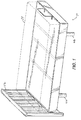
FIG. 1 is a perspective view of an adjustable mattress foundation of the invention, with a mattress supported thereon, in a flat configuration. -
FIG. 2 is a perspective view of the adjustable mattress foundation ofFIG. 1 in an inclined or raised configuration. -
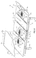
FIG. 3 is an exploded, top perspective view of the adjustable mattress foundation ofFIG. 1 . -
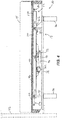
FIG. 4 is a cutaway side view of the adjustable mattress foundation ofFIG. 1 in the flat configuration. -
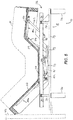
FIG. 5 is a cutaway side view of the adjustable mattress foundation ofFIG. 1 in the inclined or raised configuration. -
FIG. 6 is a top perspective view of the adjustable mattress foundation ofFIG. 1 , with portions removed, illustrating three vibration motor assemblies. -
FIG. 7 is an enlarged, exploded perspective view of one of the vibration motor assemblies ofFIG. 6 . -
FIG. 8 is a cross-sectional view of one of the vibration motor assemblies through line 8-8 inFIG. 6 . -
FIG. 9 to FIG. 27 are examples being not part of the present invention. -
FIGS. 1 and2 illustrate anadjustable mattress foundation 10 that is reconfigurable between a flat configuration for supporting amattress 14 thereon in a flat orientation (FIG. 1 ), and an inclined or raised configuration for supporting themattress 14 in an inclined or raised orientation (FIG. 2 ). It should also be understood that thefoundation 10 can be adjustable to any of a number of partially inclined or raised configurations between the flat and raised configurations shown inFIGS. 1 and2 , respectively, depending upon user preference and comfort. - With reference to
FIG. 3 , the illustratedadjustable mattress foundation 10 includes a first orlower frame 18 and a second orupper frame 22 supported upon thelower frame 18. Thelower frame 18 includes fourposts 26 for supporting thefoundation 10 on a support surface (e.g., a floor) and fourrollers 30 facing the interior of thelower frame 18. Therollers 30 are rotatably supported upon fouruprights 34 which, in turn, are fixed (e.g., by welding, fasteners, or in any other suitable manner) to parallellongitudinal rails 38 of thelower frame 18. A headboard 42 (FIGS. 1 and2 ) may be coupled to thelongitudinal rails 38 in a conventional manner. - The
upper frame 22 includes spaced,parallel guide rails 46 in which therollers 30 are received to support theupper frame 22 upon the lower frame 18 (FIG. 3 ). As such, therollers 30 permit theupper frame 22 to be axially or longitudinally displaced relative to thelower frame 18 and the headboard 42 as thefoundation 10 transitions between the flat configuration shown inFIG. 1 and the inclined or raised configuration shown inFIG. 2 . With reference toFIG. 3 , theupper frame 22 includes first, second, and third movable frame portions 50a, 50b, 50c to achieve the inclined or raised orientation of themattress 14 shown inFIG. 2 , although fewer or more frame portions can be utilized in other embodiments. The first movable frame portion 50a coincides with a portion of themattress 14 upon which a user's head and upper body is supported (FIG. 3 ). The first movable frame portion 50a is pivotably coupled to across-beam 54 interconnecting theguide rails 46, such that the first movable frame portion 50a is pivotable about an axis transverse to theguide rails 46. - The second movable frame portion 50b coincides with a portion of the
mattress 14 upon which the user's upper legs or thighs are supported. The second movable frame portion 50b is pivotably coupled to anothercross-beam 58 interconnecting theguide rails 46, such that the second movable frame portion 50b is also pivotable about an axis transverse to theguide rails 46. The third movable frame portion 50c coincides with a portion of themattress 14 upon which the user's lower legs and feet are supported. The third movable frame portion 50c is pivotably coupled to the second movable frame portion 50b about an axis transverse to theguide rails 46. The third movable frame portion 50c is also pivotably coupled to theguide rails 46 via respective links 62 (see alsoFIG. 5 ). As such, a combination of theguide rails 46, the second and third movable frame portions 50b, 50c, and thelinks 62 defines or mimics a four-bar linkage. - With reference to
FIG. 3 , theadjustable mattress foundation 10 also includes twoactuators 66 supported upon theupper frame 22 and operable to selectively incline or raise the first and second movable frame portions 50a, 50b, respectively. In the illustrated embodiment of theadjustable mattress foundation 10, each of theactuators 66 includes ahousing 70, anextensible rack 74 contained within thehousing 70, and aservo motor 78 drivably coupled to therack 74 to linearly displace therack 74 between extended and retracted positions. Theadjustable mattress foundation 10 also includes a controller 82 electrically connected with theservo motors 78 of therespective actuators 66 for selectively activating theservo motors 78 to either extend or retract theracks 74 of therespective actuators 66. Alternatively, theactuators 66 may be configured for use with a pneumatic or hydraulic power source. Theactuators 66 can take other forms capable of actuating the frame portions 50a, 50b, including without limitation lead screw, screw jack, ball screw, and roller screw linear actuators, linear motors, adjustable pneumatic or hydraulic cylinders, and the like. - In the illustrated embodiment of the
adjustable mattress foundation 10, thehousings 70 of therespective actuators 66 are pivotably coupled to thecross-beams upper frame 22, while therespective racks 74 are pivotably coupled to levers 86 which, in turn, extend from the first and second movable frame portions 50a, 50b, respectively. Thelevers 86 can each form a bell crank, and can provide increased leverage on the first and second movable frame portions 50a, 50b to reduce the amount of torque theservo motors 78 must exert to extend therespective racks 74 of theactuators 66 to incline or raise the first and second movable frame portions 50a, 50b. Alternatively, the orientation of each of theactuators 66 may be reversed such that thehousings 70 are pivotably coupled to therespective levers 86 and theracks 74 are pivotably coupled to thecross-beams - With continued reference to
FIG. 3 , theadjustable mattress foundation 10 further includes anotheractuator 90 interconnecting the lower andupper frames actuators 66 to displace theupper frame 22 relative to thelower frame 18. Theactuator 90 can take any of the forms described above in connection with the earlier-describedactuators 66. Like theother actuators 66, the illustratedactuator 90 includes ahousing 94, anextensible rack 98 contained within thehousing 94, and aservo motor 102 drivably coupled to therack 98 to linearly displace therack 98 between extended and retracted positions. The controller 82 is also electrically connected with theservo motor 102 for selectively activating theservo motor 102 to either extend or retract therack 98. - In the illustrated embodiment of the
adjustable mattress foundation 10, theactuator housing 94 is pivotably coupled to one of theguide rails 46 of theupper frame 22 while therack 98 is pivotably coupled to one of thelongitudinal rails 38 of thelower frame 18. Particularly, theactuator 90 is pivotably coupled to both the right-side rails FIG. 3 . As such, theactuator 90 can be oriented substantially parallel with theguide rails 46 and thelongitudinal rails 38, and is positioned between the right-side guide andlongitudinal rails actuator 90 may be reversed such that thehousing 94 is pivotably coupled to thelower frame 18 and therack 98 is pivotably coupled to theupper frame 22. Also, theactuator 90 may instead be positioned in-board or cut-board of both the guide andlongitudinal rails actuator 90 may alternatively be positioned near the left-slide guide andlongitudinal rails actuator 90 may alternatively be positioned and coupled between any of the members interconnecting theguide rails 46 and thelongitudinal rails 38 while still performing the same actuation function of moving theupper frame 22 to different positions with respect to thelower frame 18 as will now be described. - In operation of the
adjustable mattress foundation 10, the controller 82 is operable to coordinate inclination or raising of the movable frame portions 50a, 50b, 50c with displacement of theupper frame 22 toward the headboard 42 to generally maintain the axial gap or spacing between the headboard 42 and theupper frame 22 as thefoundation 10 transitions from the flat configuration shown inFIGS. 1 and4 to the inclined or raised configuration shown inFIGS. 2 and5 . As such, the axial or longitudinal position of the user's head remains relatively unchanged, or minimally changed, with respect to the headboard 42 when thefoundation 10 transitions from the flat configuration to the inclined or raised configuration. - When the
adjustable mattress foundation 10 is initially in the flat configuration shown inFIG. 4 , the user may prompt the controller 82 to initiate inclining or raising of the first movable frame portion 50a (e.g., by depressing one or more buttons on a user interface, not shown). The controller 82, in turn, concurrently activates theactuator 66 associated with the first movable frame portion 50a as well as theactuator 90 for moving theupper frame 22 to different positions with respect to thelower frame 18. Depending upon user input or upon the manner in which the controller 82 is configured, the controller 82 may also activate theactuator 66 associated with the second and third movable frame portions 50b, 50c. By actuating theactuator 90 along with theactuator 66 associated with the movable frame portion 50a, the movable frame portions 50a can be inclined while theupper frame 22 is displaced relative to thelower frame 18. In some embodiments, the movable frame portions 50b, 50c can also or instead be inclined by theirrespective actuator 66 while theupper frame 22 is displaced relative to thelower frame 18 by theactuator 90. By actuating theactuator 90 along with theactuator 66 associated with the movable frame portion 50a, the movable frame portion 50a can be inclined while theupper frame 22 is displaced relative to thelower frame 18. Particularly, the controller 82 activates theservo motor 78 of theactuator 66 associated with the first movable frame portion 50a to extend therack 74, thereby inclining the first movable frame portion 50a and the corresponding portion of themattress 14 supported thereon. The controller 82 can activate the servo motor of theactuator 66 associated with the second and third movable frame portions 50b, 50c to extend therack 74, thereby inclining the second and third movable frame portions 50b, 50c and the corresponding portions of themattress 14 supported thereon. - Concurrently with inclining movement of the first frame portion 50a as just described (and in some embodiments, also or instead with movement of the second and third frame portions 50b, 50c), the controller 82 activates the
servo motor 102 of theactuator 90 to extend therack 98. In those cases where the first movable frame portion 50a is inclined as just described, the concurrent activation of theservo motor 102 of theactuator 90 displaces theupper frame 22 toward the headboard 42 (FIG. 5 ). Similarly, in some embodiments in those cases where the second and third movable frame portions 50b, 50c are inclined as just described, the concurrent activation of theservo motor 102 of theactuator 90 also displaces theupper frame 22, such as toward a footboard (not shown). In some embodiments, the controller 82 is configured so that theservo motor 102 of theactuator 90 is not activated (to displace theupper frame 22 with respect to the lower frame 18) if only the second and third movable frame portions 50b, 50c have been inclined, or is configured so that theservo motor 102 of theactuator 90 is not activated (to displace theupper frame 22 with respect to the lower frame 18) if only the first movable frame portion 50a has been inclined. However, it will be appreciated that in many applications, it is desirable that theactuator 90 is activated to displace theupper frame 22 toward the headboard end of thelower frame 18 if the first movable frame portion 50a has been inclined in order to perform a "wall-hugging" motion. - When the
adjustable mattress foundation 10 is initially in the inclined or raised configuration shown inFIG. 5 , the user may prompt the controller 82 to initiate reclining or lowering of the first movable frame portion 50a (e.g., by depressing one or more buttons on the user interface, not shown). The controller 82, in turn, concurrently activates theactuator 66 associated with the first movable frame portion 50a as well as theactuator 90 for moving theupper frame 22 to different positions with respect to thelower frame 18. Depending upon user input or upon the manner in which the controller 82 is configured, the controller 82 may also activate theactuator 66 associated with the second and third movable frame portions 50b, 50c. By actuating theactuator 90 along with theactuator 66 associated with the movable frame portion 50a, the movable frame portion 50a can be reclined while theupper frame 22 is displaced relative to thelower frame 18. In some embodiments, the movable frame portions 50b, 50c can also or instead be reclined by theirrespective actuator 66 while theupper frame 22 is displaced relative to thelower frame 18 by theactuator 90. By actuating theactuator 90 along with theactuator 66 associated with the movable frame portion 50a, the movable frame portion 50a can be reclined while theupper frame 22 is displaced relative to thelower frame 18. Particularly, the controller 82 activates theservo motor 78 of theactuator 66 associated with the first movable frame portion 50a to retract therack 74, thereby reclining the first movable frame portion 50a and the corresponding portion of themattress 14 supported thereon. The controller 82 can activate the servo motor of theactuator 66 associated with the second and third movable frame portions 50b, 50c to retract therack 74, thereby reclining the second and third movable frame portions 50b, 50c and the corresponding portions of themattress 14 supported thereon. - Concurrently with the reclining movement of the first frame portion 50a as just described (and in some embodiments, also or instead with movement of the second and third frame portions 50b, 50c), the controller 82 activates the
servo motor 102 of theactuator 90 to retract therack 98. In those cases where the first movable frame portion 50a is reclined as just described, the concurrent activation of theservo motor 102 of theactuator 90 displaces theupper frame 22 away from the headboard 42. Similarly, in some embodiments in those cases where the second and third movable frame portions 50b, 50c are reclined as just described, the concurrent activation of theservo motor 102 of theactuator 90 also displaces theupper frame 22, such as away from a footboard (not shown). In some embodiments, the controller 82 is configured so that theservo motor 102 of theactuator 90 is not activated (to displace theupper frame 22 with respect to the lower frame 18) if only the second and third movable frame portions 50b, 50c have been reclined, or is configured so that theservo motor 102 of theactuator 90 is not activated (to displace theupper frame 22 with respect to the lower frame 18) if only the first movable frame portion 50a has been reclined. However, it will be appreciated that in many applications, it is desirable that theactuator 90 is activated to displace theupper frame 22 away from the headboard end of thelower frame 18 if the first movable frame portion 50a has been reclined in order to perform a "wall-hugging" motion. - Rather than coordinating concurrent operation of the
actuators foundation 10 as described herein, the controller 82 may activate theactuator 90 only after the first movable frame portions 50 is fully inclined to displace theupper frame 22 relative to the headboard 42 andlower frame 18. Similarly, rather than coordinating concurrent operation of theactuators actuator 90 before the first movable frame portion 50a is declined to displace theupper frame 22 relative to the headboard 42 andlower frame 18. - With reference to
FIG. 6 , the illustratedadjustable mattress foundation 10 includes threevibration motor assemblies 106 suspended fromrespective panels 110 attached to the first movable frame portion 50a, the two fixedcross-beams upper frame 22, and the third movable frame portion 50c. Thevibration motor assemblies 106, when activated, impart massaging vibrations to the upper body, the waist or hips, and the lower legs of a user supported upon themattress 14. Although threevibration motor assemblies 106 are in the particular locations just described, it will be appreciated that fewer or morevibration motor assemblies 106 can be provided in any locations on any of thepanels 110 of themattress foundation 10, and that multiplevibration motor assemblies 106 can be suspended at different locations on thesame panel 110, in some embodiments. - With reference to
FIG. 7 , eachvibration motor assembly 106 includes avibration motor 114 and acover 118 at least partially enclosing thevibration motor 114. In the illustrated embodiment of thevibration motor assembly 106, thecover 118 includes anouter shell 122 and aliner 126 at least partially positioned or nested within theouter shell 122 and disposed between thevibration motor 114 and theouter shell 122. In the illustrated embodiment of thevibration motor assembly 106, theliner 126 is adhesively coupled to theouter shell 122 to unitize theliner 126 andouter shell 122. Alternatively, theliner 126 may be loosely retained or positioned within theouter shell 122. - The
outer shell 122 and theliner 126 are each made of a foam material. However, the foam material of theouter shell 122 has a different density and hardness than that of theliner 126. In some alternative embodiments, the foam material of theouter shell 122 has substantially the same density or substantially the same hardness as that of theliner 126. In the illustrated embodiment, theouter shell 122 is made of a more rigid and dense foam material (e.g., a closed-cell polymer foam), while theliner 126 is made of a less rigid and dense foam material (e.g., an open-cell polymer foam). Theouter shell 122 andliner 126 work in conjunction to attenuate the magnitude of noise emitted by thevibration motor 114 and to attenuate the magnitude of vibration transferred from thevibration motor 114 to theparticular panel 110 from which thevibration motor assembly 106 is suspended. Separately, the foam material chosen for theliner 126 includes vibration-attenuation properties that yield most of the vibration-attenuation capability of thecover 118, while the foam material chosen for theouter shell 122 includes noise-attenuation properties that yield most of the noise-attenuation capability of thecover 118 while providing a degree of structural rigidity to thecover 118. - With reference to
FIGS. 7 and 8 , theadjustable mattress foundation 10 includesdual supports 130 suspending thevibration motor assembly 106 relative to thepanel 110. Although twosupports 130 are shown inFIG. 7 , asingle support 130 or three ormore supports 130 can instead be used as desired. Also, although not shown in their entirety, thefoundation 10 includes additional identical supports 130 (FIG. 6 ) suspending the othervibration motor assemblies 106 to thepanels 110. Particularly, thepanels 110 includerespective apertures 134 through which thevibration motor assemblies 106 are received. Each of thesupports 130 extends through theaperture 134 for mounting to atop surface 138 of thepanel 110. Alternatively, thesupports 130 may extend through theaperture 134 for mounting to an upper surface of thepanel 110 not coinciding with thetop surface 138. For example, thesupports 130 may be mounted to a notched, upper surface or upwardly facing surface of thepanel 110 between the top surface and a bottom surface 142 (FIG. 8 ) of thepanel 110. - With reference to
FIGS. 7 and 8 , thesupports 130 are configured asflexible straps 146 each having opposed ends 150 attached to thetop surface 138 of thepanel 110. In the illustrated embodiment of theadjustable mattress foundation 10, theends 150 of thestraps 146 are fastened to thetop surface 138 of thepanel 110 usingstaples 154. Alternatively, different fasteners, adhesives, and the like may be utilized to secure thestraps 146 to thepanel 110. Theflexible straps 146 each include an adjustable length to account for slight differences in the size of the foam covers 118 of thevibration motor assemblies 106. In the illustrated embodiment, eachstrap 146 includes afirst segment 158, asecond segment 162, and abuckle 166 interconnecting the first andsecond segments second segment 162 includes hook and loop fasteners (not shown) to permit a distal portion of thesecond segment 162 to be overlaid with and affixed to a proximal portion of thesecond segment 162. - The illustrated
vibration motor 114 includes aflange 170 and a motor housing 174 attached to theflange 170. Theflange 170 is generally flat and is located above the motor housing 174 from the frame of reference ofFIG. 8 . Theflange 170 is also positioned within an opening 178 in thecover 118 such that theflange 170 is generally co-planar with thetop surface 138 of thepanel 110. Theadjustable mattress foundation 10 further includes afabric sheet 182 secured to thetop surface 138 of each of the panels 110 (FIG. 6 ). Thesheet 182 is fastened to thetop surface 138 of the panels 110 (e.g., using staples 186 or other suitable fasteners or fastening material) and overlies each of thevibration motors 114 to limit an extent to which thecovers 118 and thevibration motors 114 of the respectivevibration motor assemblies 106 protrude from theapertures 134 in thepanels 110. Particularly, in some embodiments theflexible straps 146 may be tightened to exert a clamping force between thevibration motor assemblies 106 and thesheet 182. As such, thevibration motor assemblies 106 are maintained against the underside of themattress 14, thereby increasing the efficiency of vibration transfer into themattress 14 and in some cases reducing the amount of vibration being transferred to thepanels 110. -
FIG. 9 illustrates an example being not part of the invention of a vibration motor assembly 190. The assembly 190 includes a rigid plastic cover 194 suspended from thetop surface 138 of thepanel 110 by opposed tabs 198 (only one of which is shown inFIG. 9 ). The cover 194 also includes resilientlydeflectable fingers 202 that engage thebottom surface 142 of thepanel 110 to thereby pinch thepanel 110 between thetabs 198 andfingers 202. Thetabs 198 andfingers 202 can be integrally formed with the rest of the rigid plastic cover 194. By virtue of their shape and ability to move with respect to the rest of the rigid plastic cover 194 (note that thetabs 198 andfingers 202 can extend from adjacent portions of the rigid plastic cover 194 in a cantilevered fashion as shown), thetabs 198 andfingers 202 can be deflected by a user upon installation of the rigid plastic cover 194 on thepanel 110. Particularly, to install the cover 194 (with vibration motor assembly 190 therein) from the underside of thepanel 110, an installer can squeeze thetabs 198 inward to clear the edges of theaperture 134 in thepanel 110, and can then insert the cover 194 into theaperture 134 until thefingers 202 contact the underside of thepanel 110. In this regard, the clearance between the ends of thetabs 198 and the ends of thefingers 202 can be smaller than the thickness of thepanel 110 therebetween, thereby causing thetabs 198 andfingers 202 to remain in deflected states after the rigid plastic cover 194 has been installed in theaperture 134. By virtue of this relationship between thetabs 198 and fingers 202 (collectively also referred to simply as "projections" of the rigid plastic cover 194) and thepanel 110, the rigid plastic cover 194 can be tightly secured to thepanel 110, with a biasing force exerted by thetabs 198 andfingers 202 against thepanel 110. Such a tightly-secured relationship between the rigid plastic cover 194 and thepanel 110 can be very desirable in light of the fact that the rigid plastic cover 194 can be subjected to significant vibration over the lifespan of themattress foundation 110. - Although the cover 194 in the illustrated embodiment is described above as being made of rigid plastic, it will be appreciated that covers constructed of other resilient materials can perform the same or similar functions, and can instead be used. By way of example, the cover 194 can instead comprise aluminum, steel, or other metal, composite materials, and the like.
-
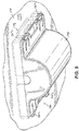
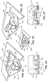
FIGS. 10 and 11 illustrate another example being not part of the invention of avibration motor assembly 206. Theassembly 206 includes acover 210 mounted (e.g., using fasteners, fastening material, and the like) to thebottom surface 142 of thepanel 110 and avibration motor 114 received within a cavity of thecover 210. Thecover 210 includes resilientlydeflectable fingers 214 that define the upper extent of the cavity. By virtue of their resiliently deformable nature, thefingers 214 exert a clamping force on thevibration motor 114 to tightly hold thevibration motor 114 within thecover 210 while positioning thevibration motor flange 170 in proper relationship in contact with the underside of a mattress (not shown). -
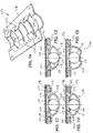
FIG. 12 illustrates yet another example being not part of the invention of avibration motor assembly 218. Theassembly 218 includes a cover 222 suspended from an upper surface of thepanel 110 and avibration motor 114 received within a cavity of the cover 222. The cover 222 includes resilientlydeflectable fingers 226 that define the upper extent of the cavity. By virtue of their resiliently deformable nature, thefingers 226 exert a clamping force on thevibration motor 114 to tightly hold thevibration motor 114 within the cover 222 while positioning thevibration motor flange 170 in proper relationship in contact with the underside of a mattress (not shown). The cover 222 includesadditional tabs 230 adjacent thebottom surface 142 of thepanel 110 that cooperate withtabs 230 adjacent thetop surface 138 of thepanel 110 to hold the cover 222 in place in thepanel 110. Although either or bothsuch tabs 230 can be recessed within theadjacent surface panel 110, only theupper tabs 230 are recessed within thepanel 110 in the illustrated embodiment ofFIG. 12 . -
FIG. 13 illustrates a further example being not part of the invention of a vibration motor assembly 234. The assembly 234 includes a cover 238 suspended from an upper surface of thepanel 110 and avibration motor 114 received within a cavity of the cover 238. The cover 238 includes resilientlydeflectable fingers 242 that define the upper extent of the cavity. By virtue of their resiliently deformable nature, thefingers 242 exert a clamping force on thevibration motor 114 to tightly hold thevibration motor 114 within the cover 238 while positioning thevibration motor flange 170 in proper relationship in contact with the underside of a mattress (not shown). Like theupper tabs 230 in the embodiment ofFIG. 12 , the cover 238 also has upper tabs that are recessed within theadjacent surface 138 of thepanel 110. -
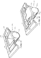
FIG. 14 illustrates another example being not part of the invention of avibration motor assembly 246. Theassembly 246 includes acover 250 suspended from thepanel 110 and avibration motor 114 received within a cavity of thecover 250. Thecover 250 includes resilientlydeflectable fingers 254 that define the upper extent of the cavity. By virtue of their resiliently deformable nature, thefingers 254 exert a clamping force on thevibration motor 114 to tightly hold thevibration motor 114 within thecover 250 while positioning thevibration motor flange 170 in proper relationship in contact with the underside of a mattress (not shown). Thecover 250 includes laterally extendingtabs 258 that are received within corresponding slots orgrooves 262 in the middle of thepanel 110 for suspending thecover 250 from thepanel 110. -
FIG. 15 illustrates yet another example being not part of the invention of avibration motor assembly 266. Theassembly 266 includes acover 270 suspended from an upper surface of thepanel 110 and avibration motor 114 received within a cavity of thecover 270. Thecover 270 includes resilientlydeflectable fingers 274 that define the upper extent of the cavity. By virtue of their resiliently deformable nature, thefingers 274 exert a clamping force on thevibration motor 114 to tightly hold thevibration motor 114 within thecover 270 while positioning thevibration motor flange 170 in proper relationship in contact with the underside of a mattress (not shown). In the illustrated embodiment ofFIG. 15 , the lower extent of the cavity is defined by aconvex surface 278 of thecover 270, thereby providing a reduced amount of contact between thecover 270 and thevibration motor 114. In this manner, thecover 270 can exhibit vibration reduction characteristics in order to prevent unwanted transmission of vibration to thepanel 110. -
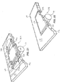
FIG. 16 illustrates a further example being not part of the invention of a vibration motor assembly 282, with the vibration motor omitted for clarity. The assembly 282 includes acover 286 includingmultiple stirrups 290 upon which the vibration motor is supported and resilientlydeflectable fingers 294 that engage the vibration motor. By virtue of their resiliently deformable nature, thefingers 294 exert a clamping force on the vibration motor to tightly hold the vibration motor within thecover 286 while positioning thevibration motor flange 170 in proper relationship in contact with the underside of a mattress (not shown). Thecover 286 may be mounted to either the top or bottom surface of the panel (not shown). -
FIG. 17 illustrates another example being not part of the invention of avibration motor assembly 298. Theassembly 298 includes acover 302 suspended from an upper surface of thepanel 110 and avibration motor 114 supported by thecover 302 made of a sheet of material (e.g., fabric, plastic, and the like). Thecover 302 is configured as anelastic sling 306 to allow thevibration motor 114 to float with respect to thepanel 110. As such, the amount of vibration transferred to thepanel 110 is reduced. Acollar 310 is positioned around theflange 170 of thevibration motor 114 to center thevibration motor 114 within thesling 306 and to inhibit lateral shifting of thevibration motor 114 within thesling 306. -
FIG. 18 illustrates yet another example being not part of the invention of avibration motor assembly 314. Theassembly 314 includes multipleelastic straps 318 suspended from thetop surface 138 of thepanel 110 and a vibration motor 322 supported by thestraps 318. In a similar manner as theelastic sling 306 inFIG. 17 , thestraps 318 allow the vibration motor 322 to float with respect to thepanel 110. As such, the amount of vibration transferred to thepanel 110 is reduced. Thestraps 318 can be threaded throughcorresponding slots 326 in the vibration motor 322 to center the vibration motor 322 within thestraps 318 and to inhibit lateral shifting of the vibration motor 322. -
FIG. 19 illustrates a further example being not part of the invention of avibration motor assembly 330. Theassembly 330 includes a rigid cover 334 mounted to thebottom surface 142 of thepanel 110 and avibration motor 114 received within a cavity of the cover 334. Vibration isolators 338 (e.g., gel isolators) are utilized to reduce the transfer of vibration from thevibration motor 114 to the cover 334 and the attachedpanel 110, whereas vibration is transmitted upward from thevibration motor flange 170 to a mattress upon the pane! 110. -
FIG. 20 illustrates another example being not part of the invention of avibration motor assembly 342. Theassembly 342 includes arigid cover 346 mounted to thebottom surface 142 of thepanel 110 and avibration motor 114 received within a cavity of thecover 346. Theassembly 342 also includes anadjustment mechanism 350 positioned between thecover 346 and thevibration motor 114 for varying the spacing between thevibration motor 114 and the overlyingmattress 14, thereby enabling an installer or user to vary the resultant intensity of vibration transferred to themattress 14. Theadjustment mechanism 350 includes, for example, astirrup 354 in which thevibration motor 114 is seated and a knob withsetscrew 358 threaded to thecover 346 for raising and lowering thestirrup 354 and themotor 114 relative to themattress 14. -
FIG. 21 illustrates yet another example being not part of the invention of a vibration motor assembly 362. The assembly 362 includes avibration motor 114 andmultiple clamps 366 securing thevibration motor 114 to thepanel 110. Particularly, theclamps 366 attach to thevibration motor 114 through existing holes in theflange 170. Thepanel 110 includes a corresponding number ofnotches 370 in which theclamps 366 are received to make theclamps 366 flush with thetop surface 138 of thepanel 110. Ariser pad 374 may be utilized on theflange 170 to account for any gap between theflange 170 and thetop surface 138 of thepanel 110. -
FIG. 22 illustrates a further example being not part of the invention of avibration motor assembly 378. Theassembly 378 includes avibration motor 114 suspended from an upper recessedsurface 384 of thepanel 110 about a periphery of the aperture in thepanel 110 and afoam isolator 386 positioned between theflange 370 of thevibration motor 114 and the upper recessedsurface 384 of thepanel 110. The foam isolator 186 attenuates the magnitude of vibration transferred to thepanel 110. -
FIGS. 23 and 24 illustrate another example being not part of the invention of avibration motor assembly 390. Theassembly 390 includes a rigid cover 394 mounted to thebottom surface 142 of thepanel 110 and avibration motor 114 received within a cavity of the cover 394. Ariser pad 398 with multiple protrusions 402 (each of which has barbs, in the illustrated embodiment) is positioned on theflange 170 of thevibration motor 114, with theprotrusions 402 being inserted into themattress 14. In this manner, vibration from thevibration motor 114 can be transferred to themattress 14 through theriser pad 398 and theprotrusions 402. -
FIG. 25 illustrates yet another example being not part of the invention of a vibration motor assembly 406. The assembly 406 includes arigid cover 410 mounted to thebottom surface 142 of thepanel 110 and avibration motor 114 received within a cavity of thecover 410. A riser pad 414 with multiple protrusions in the form of ribs 418 is positioned on theflange 170 of thevibration motor 114, with the ribs 418 being inserted into an overlying mattress (not shown). As such, vibration from thevibration motor 114 can be transferred to the mattress through the riser pad 414 and the ribs 418. -
FIGS. 26 and 27 illustrate a further example being not part of the invention of a vibration motor assembly 422. The assembly 422 includes arigid cover 426 mounted to thebottom surface 142 of thepanel 110 and avibration motor 114 received within a cavity of thecover 426. Atray 430 is recessed into themattress 14, with thevibration motor 114 being received at least partially within thetray 430. As such, vibration from thevibration motor 114 can be transferred to themattress 14 through thetray 430.
Claims (14)
- An adjustable mattress foundation (10) comprising:a frame (22) including at least one movable frame portion (50);a panel (110) coupled for movement with the movable frame portion, the panel (110) including a lower surface in facing relationship with the movable frame portion (50) and an upper surface;an actuator (66) supported upon the frame (22) and operable to selectively incline the at least one movable frame portion (50);a vibration motor (114); anda support (130) suspending the vibration motor (114) relative to the panel (110), the support (130) being mounted to the upper surface of the panel (110),wherein the support (130) is a flexible strap (146) having opposed first and second ends (150) attached to the upper surface of the panel (110), andwherein a length of the flexible strap (146) is adjustable.
- The adjustable mattress foundation (10) of claim 1, wherein the flexible strap (146) includes a first segment (158), a second segment (162), and a buckle (166) interconnecting the first and second segments.
- The adjustable mattress foundation (10) of any preceding claim, wherein the flexible strap (146) is a first flexible strap, and wherein the adjustable mattress foundation (10) further includes a second flexible strap having opposed first and second ends attached to the upper surface of the panel (110).
- The adjustable mattress foundation (10) of any preceding claim, wherein the first and second ends (150) of the flexible strap (146) are stapled to the upper surface of the panel (110).
- The adjustable mattress foundation (10) of claim 1, wherein the upper surface of the panel (110) coincides with a top surface (138) of the panel (110).
- The adjustable mattress foundation (10) of claim 1, further comprising a cover (118) at least partially enclosing the vibration motor (114), wherein the panel (110) includes an aperture (134), and wherein the cover (118) is at least partially received within the aperture (134), wherein the vibration motor (114) includes a flange (170) and a motor housing (174) attached to the flange (170), and wherein the flange (170) is located above the motor housing (174), and wherein the cover (118) includes an opening, and wherein the flange (170) is positioned in the opening.
- The adjustable mattress foundation (10) of claim 6, wherein the vibration motor (114) and the cover (118) are suspended relative to the panel (110) by the support (130).
- The adjustable mattress foundation (10) of claim 6 or 7, further comprising a sheet (182) secured to the upper surface of the panel (138), wherein the sheet (182) at least partially overlies the vibration motor (114) to limit an extent to which the cover (118) and the vibration motor (114) protrude from the aperture (134) in the panel (110).
- The adjustable mattress foundation (10) of claim 8, wherein the sheet (182) is stapled to the upper surface of the panel (110), and/or wherein the support (130) clamps the cover (118) and the vibration motor (114) against the sheet (182), and/or, wherein the sheet (182) is made of a fabric material.
- The adjustable mattress foundation (10) of claim 1, further comprising a cover (118) at least partially enclosing the vibration motor (114), wherein the cover (118) includes an outer shell (122) and a liner (126) at least partially positioned within the outer shell (122).
- The adjustable mattress foundation (10) of claim 10, wherein the liner (126) is positioned between the vibration motor (114) and the outer shell (122), and/or wherein the outer shell (122) is made of a first foam material, and wherein the liner (122) is made of a second foam material.
- The adjustable mattress foundation (10) of claim 11, wherein the first foam material is more rigid than the second foam material, and/or wherein the first foam material is more dense than the second foam material, and/or wherein the second foam material attenuates the magnitude of vibration emitted by the vibration motor (114), and/or wherein the first foam material attenuates the magnitude of noise being transferred from the vibration motor (114) to the panel (110), and/or wherein the liner (126) is adhesively coupled to the outer shell (122).
- An assembly for generating vibration of a mattress supported upon a panel (110) of a mattress foundation, the panel (110) having an aperture (134) therein, the assembly comprising:a vibration motor (114); anda support (130) suspending the vibration motor (114) relative to the panel (110), the support (130) mounted to the upper surface of the panel (110), extending beneath the vibration motor (114), and suspending the vibration motor (114) in a position substantially aligned with the aperture (134) in the panel (110) and located at least partially below the panel (110),wherein the support (130) is a flexible strap (146) having opposed first and second ends (150) attached to the upper surface of the panel (110), andwherein a length of the flexible strap (146) is adjustable.
- A mattress foundation comprising:a frame (22) ;a panel (110) supported by the frame (22) and adapted for support (130) of a mattress thereon, the panel (110) including an upper surface and an oppositely-facing lower surface;a vibration motor (114); anda support (130) suspending the vibration motor (114) relative to the panel (110), the support (130) being mounted to the upper surface of the panel (110),wherein the support (130) is a flexible strap (146) having opposed first and second ends (150) attached to the upper surface of the panel (110), andwherein a length of the flexible strap (146) is adjustable.
Priority Applications (1)
| Application Number | Priority Date | Filing Date | Title |
|---|---|---|---|
| PL12881605T PL2877059T3 (en) | 2012-07-27 | 2012-07-27 | Mattress foundation including vibration motors and mounting arrangements therefor |
Applications Claiming Priority (1)
| Application Number | Priority Date | Filing Date | Title |
|---|---|---|---|
| PCT/US2012/048613 WO2014018057A1 (en) | 2012-07-27 | 2012-07-27 | Mattress foundation including vibration motors and mounting arrangements therefor |
Publications (3)
| Publication Number | Publication Date |
|---|---|
| EP2877059A1 EP2877059A1 (en) | 2015-06-03 |
| EP2877059A4 EP2877059A4 (en) | 2016-01-27 |
| EP2877059B1 true EP2877059B1 (en) | 2017-09-06 |
Family
ID=49997686
Family Applications (1)
| Application Number | Title | Priority Date | Filing Date |
|---|---|---|---|
| EP12881605.5A Active EP2877059B1 (en) | 2012-07-27 | 2012-07-27 | Mattress foundation including vibration motors and mounting arrangements therefor |
Country Status (9)
| Country | Link |
|---|---|
| US (1) | US10039387B2 (en) |
| EP (1) | EP2877059B1 (en) |
| JP (1) | JP5965548B2 (en) |
| CN (1) | CN104918519B (en) |
| CA (1) | CA2879978C (en) |
| DK (1) | DK2877059T3 (en) |
| ES (1) | ES2645242T3 (en) |
| PL (1) | PL2877059T3 (en) |
| WO (1) | WO2014018057A1 (en) |
Cited By (1)
| Publication number | Priority date | Publication date | Assignee | Title |
|---|---|---|---|---|
| DE202019105682U1 (en) | 2019-09-20 | 2019-10-28 | Winfried Berger | Mattress with vibration |
Families Citing this family (29)
| Publication number | Priority date | Publication date | Assignee | Title |
|---|---|---|---|---|
| US20140352068A1 (en) * | 2013-06-03 | 2014-12-04 | Jiaxing Shufude Electric Bed Co., Ltd. | Electric motorized bed |
| US20150182418A1 (en) * | 2014-01-02 | 2015-07-02 | Select Comfort Corporation | Massage furniture item and method of operation |
| WO2016065317A1 (en) * | 2014-10-24 | 2016-04-28 | Ergomotion, Inc. | Massage motor support apparatus for an adjustable bed |
| CN104433486B (en) | 2014-10-29 | 2018-03-06 | 嘉兴赛诺机械有限公司 | Electric drive mechanism and electric furniture |
| US9918556B2 (en) * | 2015-01-16 | 2018-03-20 | Ascion, Llc | Adjustable bed foundation |
| US10028873B2 (en) * | 2015-01-21 | 2018-07-24 | Tempur-Pedic Management, Llc | Adjustable bed foundation with rotating head section |
| WO2016160369A1 (en) | 2015-03-20 | 2016-10-06 | Zoll Medical Corporation | Systems for self-testing an ambulatory medical device |
| US11224294B2 (en) | 2015-06-19 | 2022-01-18 | Tempur World, Llc | Adjustable base assemblies, systems and related methods |
| US10299604B2 (en) * | 2015-09-08 | 2019-05-28 | Ergomotion, Inc. | Massage motor suspension system |
| US11709747B2 (en) | 2016-01-08 | 2023-07-25 | Zoll Medical Corporation | Patient assurance system and method |
| US11617538B2 (en) | 2016-03-14 | 2023-04-04 | Zoll Medical Corporation | Proximity based processing systems and methods |
| US10426342B2 (en) | 2016-03-31 | 2019-10-01 | Zoll Medical Corporation | Remote access for ambulatory medical device |
| CN105769412B (en) * | 2016-04-08 | 2017-09-08 | 宋兴东 | One analgesic bone is reset bed |
| US20180008049A1 (en) * | 2016-07-06 | 2018-01-11 | Chuan-Hang Shih | Frame of electric bed |
| DE102016217354A1 (en) * | 2016-09-12 | 2018-03-15 | Brose Fahrzeugteile Gmbh & Co. Kommanditgesellschaft, Coburg | Vehicle seat element, insert element, upholstery, method for producing a vehicle seat element |
| US11076704B2 (en) * | 2016-11-16 | 2021-08-03 | Sino International Group Limited | Motorized bed |
| CN110213981A (en) * | 2016-12-16 | 2019-09-06 | 紫色创新有限责任公司 | Adjustable pedestal and correlation technique |
| US12329283B2 (en) * | 2019-01-07 | 2025-06-17 | Nisco Co., Ltd | Foldable connection mechanism and adjustable bed system therewith |
| US20200221882A1 (en) * | 2019-01-10 | 2020-07-16 | Nisco Co., Ltd | Adjustable bed system having fans |
| US20200359806A1 (en) * | 2019-01-10 | 2020-11-19 | Nisco Co., Ltd | Wall-hugger adjustable bed with power fan system |
| KR102175145B1 (en) * | 2019-03-14 | 2020-11-05 | 주식회사 부성엘티에스 | Motion bed |
| USD931015S1 (en) * | 2019-06-25 | 2021-09-21 | Jae Duk Lee | Bed frame |
| TWM590393U (en) * | 2019-10-25 | 2020-02-11 | 丰上工業股份有限公司 | Furniture bed with vibration effect |
| FR3102724B1 (en) * | 2019-10-31 | 2022-04-29 | Faurecia Sieges Dautomobile | Vibration device integrated into a seat |
| US20210307522A1 (en) * | 2020-04-07 | 2021-10-07 | Lg Electronics Inc. | Bed |
| CN112545244A (en) * | 2020-12-01 | 2021-03-26 | 上海金字塔睡眠科技有限公司 | Physiotherapy and sleep-aid power device |
| US12114777B2 (en) * | 2021-12-23 | 2024-10-15 | Chuan-Hang Shih | Foldable electric bed |
| TWI803397B (en) * | 2022-07-21 | 2023-05-21 | 施權航 | electric bed |
| US20250134762A1 (en) * | 2023-01-20 | 2025-05-01 | Tempur World, Llc | Methods, systems, and assemblies for transmitting a vibroacoustic stimulation into a mattress |
Family Cites Families (114)
| Publication number | Priority date | Publication date | Assignee | Title |
|---|---|---|---|---|
| US5188096A (en) | 1990-03-15 | 1993-02-23 | Yoo Young Yoon | Massage apparatus |
| CN2103334U (en) | 1990-08-04 | 1992-05-06 | 陈海就 | Massaging bed pad |
| JPH057239U (en) | 1991-05-03 | 1993-02-02 | カツトラー スタンレイ | Pine surge device |
| US5140976A (en) | 1991-08-27 | 1992-08-25 | Cheng Tzu Keng | Massager with mercury switch |
| CN2102762U (en) * | 1991-11-05 | 1992-04-29 | 高松涛 | Electric magnetic treating massage cushion |
| CN2138494Y (en) | 1991-12-19 | 1993-07-21 | 上海英特电器厂 | Hammer type massage solft cushion |
| US5314403A (en) | 1992-04-24 | 1994-05-24 | Shaw Richard T | Apparatus for the enhancement of the enjoyment of the extremely low frequency component of music |
| CN1033360C (en) | 1992-08-30 | 1996-11-27 | 陈海就 | Universal rolling massage magnetic therapy mattress |
| CA2087506A1 (en) | 1993-01-18 | 1994-07-19 | Simon Liang | Multi-function cushion |
| US5411468A (en) | 1993-04-23 | 1995-05-02 | Chen; K. C. | Massaging pillow device used in a car |
| US5344437A (en) | 1993-05-10 | 1994-09-06 | Sub I.P., Inc. | Massaging therapeutic pillow with removable ice pack |
| US5424592A (en) | 1993-07-01 | 1995-06-13 | Aura Systems, Inc. | Electromagnetic transducer |
| US5374238A (en) | 1993-07-19 | 1994-12-20 | Xiao; Ji | Vibrating neck rest for the passenger seat of a motor vehicle |
| US5462515A (en) | 1993-12-21 | 1995-10-31 | Tseng; Chin-Tsun | Multi-functional automatic circular massaging device |
| US5544376A (en) | 1994-01-31 | 1996-08-13 | Maxwell Products, Inc. | Articulated bed with customizable remote control |
| US5539943A (en) | 1994-03-08 | 1996-07-30 | Ssi Medical Services, Inc. | Apparatus and method for percussion of fluidized support surface |
| US5393297A (en) | 1994-03-14 | 1995-02-28 | Kristoff; Beverly A. | Neck pillows with internal vibrational mechanisms |
| US5540651A (en) | 1994-04-20 | 1996-07-30 | Thomas M. Risch | Waterproof hydrotherapy bed |
| US5503618A (en) | 1994-10-06 | 1996-04-02 | Rey; Rafael R. | Hydromassage pillow |
| US5599280A (en) | 1995-03-20 | 1997-02-04 | Wolden; Wallace W. | Therapeutic wrist device having vibration and heat |
| JPH09140757A (en) | 1995-11-24 | 1997-06-03 | Matsushita Electric Works Ltd | Chair type massage machine |
| JPH09206343A (en) | 1996-01-31 | 1997-08-12 | Atom Medical Kk | Mat device for incubator |
| US6077238A (en) | 1996-02-29 | 2000-06-20 | Homedics, Inc. | Massaging apparatus with micro controller using pulse width modulated signals |
| US5713832A (en) | 1996-04-23 | 1998-02-03 | Product Development Consulting Inc. | Massaging furniture with electric vibration device and eccentric rotor |
| US5857986A (en) | 1996-05-24 | 1999-01-12 | Moriyasu; Hiro | Interactive vibrator for multimedia |
| US5771514A (en) | 1996-07-08 | 1998-06-30 | Chris Wilhoit | Adjustable contour pillow |
| US5807287A (en) | 1996-08-01 | 1998-09-15 | Cheng; Tzu-Keng | Massaging apparatus with audio signal control |
| US6648840B2 (en) | 1996-08-02 | 2003-11-18 | Salton, Inc. | Microcontroller based massage system |
| US6290661B1 (en) | 1996-09-24 | 2001-09-18 | Inseat Solutions Llc | Infrared control system for a massage chair |
| US6027463A (en) | 1996-12-27 | 2000-02-22 | Moriyasu; Hiro | Music massager |
| US5951500A (en) | 1997-01-03 | 1999-09-14 | Jb Research, Inc. | Audio responsive massage system |
| US5836900A (en) | 1997-03-19 | 1998-11-17 | Jb Research, Inc. | Massaging apparatus having transformable pad |
| CA2207192C (en) | 1997-06-05 | 2000-10-10 | Global Upholstery Company | Chair equipped with massage apparatus |
| TW352571U (en) | 1997-06-14 | 1999-02-11 | Jia-Shi Huang | Cushion with massage function |
| US6006379A (en) * | 1997-08-04 | 1999-12-28 | Patmark Company, Inc. | Articulating bed frame |
| US5895365A (en) | 1997-12-11 | 1999-04-20 | Tomlinson; Terry | Massaging bedrest cushion |
| US6101647A (en) * | 1998-03-10 | 2000-08-15 | L&P Property Management Company | Adjustable bed |
| US6142963A (en) | 1998-03-10 | 2000-11-07 | Black; John W. | Vibrating baby blanket |
| US5842241A (en) | 1998-04-09 | 1998-12-01 | Cooper; Glen T. | Water jet massaging waterbed mattress |
| US6024407A (en) | 1998-04-10 | 2000-02-15 | Somatron Corporation | Vibrating particle material filled furniture |
| US6375630B1 (en) | 1998-04-28 | 2002-04-23 | Inseat Solutions, Llc | Microcontroller based massage system |
| US6110131A (en) | 1998-05-28 | 2000-08-29 | Jb Research, Inc. | Vibrating chair with shrink-wrapped vibrator |
| US6053880A (en) | 1998-09-08 | 2000-04-25 | Jb Research, Inc. | Massaging system having isolated vibrators |
| US6182313B1 (en) | 1999-03-22 | 2001-02-06 | Paul William Eschenbach | Therapeutic head cradle |
| US6120468A (en) | 1999-06-11 | 2000-09-19 | Tseng; Chin-Chun | Sound-controllable multistage massager equipped with LCD device |
| US6175981B1 (en) | 1999-07-12 | 2001-01-23 | Delilah Navarro Lizama | Portable vibrating sleep pad |
| US6106490A (en) | 1999-07-16 | 2000-08-22 | Shaw; George B. | Torso exercise and traction machine with vibrational therapy pads |
| US6682494B1 (en) | 1999-08-17 | 2004-01-27 | Inseat Solutions, Llc | Massaging system having isolated vibrators |
| US6256818B1 (en) | 1999-09-24 | 2001-07-10 | Angela Y. Hughes | Heated massage pillow |
| JP3831563B2 (en) | 1999-12-20 | 2006-10-11 | 東芝テック株式会社 | Massage device and chair type massage machine using this massage device |
| US6440092B1 (en) | 1999-12-20 | 2002-08-27 | D2Rm Corp. | Harmonic vibration massage device |
| JP4362917B2 (en) * | 2000-01-31 | 2009-11-11 | 宇部興産株式会社 | Metal foil laminate and its manufacturing method |
| US6178577B1 (en) | 2000-03-31 | 2001-01-30 | Cheng Chien-Chuan | Mattress with adjustable massage units |
| US6170602B1 (en) | 2000-05-19 | 2001-01-09 | Evelyn Kay Mann | Sound emitting and vibratable blanket |
| US6814709B2 (en) | 2000-06-16 | 2004-11-09 | Brookstone Purchasing, Inc. | Massaging bed rest cushion with light |
| US6499161B1 (en) * | 2000-09-07 | 2002-12-31 | L&P Property Management Company | Adjustable bed with vibrators |
| US6676615B2 (en) | 2000-09-29 | 2004-01-13 | Omega Patents, L.L.C. | Wireless massage device for a vehicle and associated methods |
| US20020111572A1 (en) | 2000-10-23 | 2002-08-15 | Abby Waters | Eight in one vibrating mattress pad |
| US6438779B1 (en) | 2000-11-10 | 2002-08-27 | Eric J. Brown | Knee pillow |
| US6684423B2 (en) * | 2000-12-22 | 2004-02-03 | L&P Property Management Company | Massage motor mounting for bed/chair |
| KR20010099012A (en) | 2001-08-09 | 2001-11-09 | 박영고 | Bed |
| SE518712C2 (en) * | 2001-02-05 | 2002-11-12 | Stjernfjaedrar Ab | Adjustable bed |
| US6968806B2 (en) | 2001-02-23 | 2005-11-29 | Helwig Michele M | Animal soothing system with heartbeat simulation device |
| KR100684071B1 (en) | 2001-05-04 | 2007-02-16 | 박양성 | Vibration System by Speaker Sound of Air Cushion Using 3D Woven Fabric |
| JP2003000388A (en) * | 2001-06-21 | 2003-01-07 | Aisin Seiki Co Ltd | bed |
| US20030028132A1 (en) | 2001-07-03 | 2003-02-06 | Conair Corporation | Massage pad with selectively placeable massage actuators |
| US6524263B2 (en) | 2001-07-10 | 2003-02-25 | Rui Chen | Programmable neck massaging device |
| US6626341B2 (en) | 2001-10-01 | 2003-09-30 | Carter Mitchell | Massaging book bag |
| US6723059B1 (en) | 2001-12-26 | 2004-04-20 | Ki Dong Park | Therapeutic bed with vibrating element |
| US6785922B2 (en) | 2001-12-27 | 2004-09-07 | Kolcraft Enterprises, Inc. | Mattress with internal vibrator |
| KR200274179Y1 (en) | 2002-01-11 | 2002-05-06 | 이광호 | Cushion with vibration motor |
| JP2003274468A (en) | 2002-03-14 | 2003-09-26 | Tamagawa Kasei:Kk | Low frequency sound amplifying oscillator |
| US6957454B1 (en) | 2002-04-02 | 2005-10-25 | Kitala Ann Newton | Mattress cover with massaging mechanism and heating element |
| WO2003096960A2 (en) | 2002-05-20 | 2003-11-27 | Dong-Hee Lee | Massage cushion |
| US20040021347A1 (en) | 2002-08-05 | 2004-02-05 | Bob Turudich | Bicycle saddle with vibrating massager |
| US6684426B1 (en) * | 2002-08-22 | 2004-02-03 | Lifegear, Inc. | Folding collapsible massage bed |
| WO2004024054A1 (en) | 2002-09-09 | 2004-03-25 | Family Co., Ltd. | Massaging device and forearm massaging machine |
| US6829797B2 (en) | 2002-10-08 | 2004-12-14 | Syrus Jacob Partian | Contour and topography adjusting massaging mattress |
| US7553288B2 (en) | 2003-03-10 | 2009-06-30 | Cohen Daniel E | Sound and vibration transmission pad and system |
| US7322947B2 (en) | 2003-03-26 | 2008-01-29 | Gaymar Industries, Inc. | Vibrational and pulsating cushioning device |
| US6890313B2 (en) | 2003-05-30 | 2005-05-10 | Hakjin Kim | Lie-down massager |
| US7048701B2 (en) | 2003-04-18 | 2006-05-23 | Hakjin Kim | Lie-down massager |
| US7118541B2 (en) | 2003-05-16 | 2006-10-10 | Hakjin Kim | Lie-down massager |
| US7037279B2 (en) | 2003-05-27 | 2006-05-02 | Hakjin Kim | Lie-down massager |
| US7052475B2 (en) | 2003-07-07 | 2006-05-30 | Hakjin Kim | Lie-down massager |
| US7013588B2 (en) | 2003-05-15 | 2006-03-21 | Freddie Chang | Floating massage pad structure |
| KR100724750B1 (en) | 2003-05-26 | 2007-06-07 | 패밀리 가부시키가이샤 | Chair massagers, covers for massagers, covers for leg rests and massagers |
| US6826789B1 (en) | 2003-07-08 | 2004-12-07 | Chang-Hwan Choi | Sofa equipped with radiant heating mattress for fomentation and massage |
| US6849054B1 (en) | 2003-07-21 | 2005-02-01 | Hakjin Kim | Lie-down massager |
| US6851146B1 (en) | 2003-09-12 | 2005-02-08 | Ronald J. Kristof | Neck pillow system |
| TW200514531A (en) | 2003-09-29 | 2005-05-01 | Ein Co Ltd Technical Ct | Cushion and acoustic system with the cushion |
| JP2005103252A (en) | 2003-09-29 | 2005-04-21 | Kwang-Ho Lee | Cushion device for recovery from fatigue |
| US7725962B1 (en) | 2004-02-05 | 2010-06-01 | Timothy Jon Smith | Massaging sink neck rest |
| US7228573B2 (en) | 2004-02-05 | 2007-06-12 | Timothy Jon Smith | Massaging sink neck rest |
| US7328470B2 (en) | 2004-02-20 | 2008-02-12 | Brookstone Purchasing, Inc. | Foldable massaging bed rest |
| US20060037146A1 (en) | 2004-08-19 | 2006-02-23 | Soon Teck Heng | Comfort cushion or bed |
| CN1739421A (en) | 2004-08-27 | 2006-03-01 | 叶永丰 | Air-cushion bed |
| US7361152B2 (en) | 2004-09-24 | 2008-04-22 | Matsuda Micronics Corporation | Corrugated mattress vibrator longitudinally vibrated |
| US7861334B2 (en) * | 2005-12-19 | 2011-01-04 | Stryker Corporation | Hospital bed |
| TWM267928U (en) | 2004-11-25 | 2005-06-21 | Yin-Pao Hsieh | Water wave-vibration and massage bed |
| US7727171B2 (en) | 2005-01-19 | 2010-06-01 | Toyota Boshoku Kabushiki Kaisha | Vehicle seats with plurality of pneumatic massaging elements |
| US7039970B1 (en) * | 2005-04-19 | 2006-05-09 | L&P Property Management Company | Adjustable bed |
| WO2006129981A1 (en) | 2005-06-02 | 2006-12-07 | Wan-Seok Han | Pillow for generating vibration and a negative ion |
| US7614099B2 (en) | 2005-06-08 | 2009-11-10 | Anne Goetz | Vibratable, sound-emitting, and inflatable sleeping bag for providing deep pressure |
| US7905846B2 (en) | 2005-10-06 | 2011-03-15 | Ganti Sastry K | Special bed, for bedsores therapy and massage therapy |
| US7681949B2 (en) | 2006-04-12 | 2010-03-23 | Lear Corporation | Haptic vehicle seat |
| US20080033326A1 (en) | 2006-07-13 | 2008-02-07 | Diane Evans | Mattress pad having vibrational and temperature control capabilities |
| US20080033327A1 (en) | 2006-08-04 | 2008-02-07 | Evans Zachary L | Vibrating apparatuses configured to support the body of a person, vibrating furniture covers, and methods of assembling frameless articles of furniture |
| US7712172B2 (en) | 2006-08-15 | 2010-05-11 | Daniel W Jones | Apparatus and method of providing adjustable support and massage to a sleep system |
| US7988649B1 (en) | 2006-08-30 | 2011-08-02 | Jonathan Kost | Therapeutic massage system |
| US9433546B2 (en) * | 2006-09-14 | 2016-09-06 | Ascion, Llc | Dual motion deck-on-deck bed frame |
| US20100262050A1 (en) | 2009-04-10 | 2010-10-14 | Karen Gasparovich | Infant Soothing Support Device |
| US8043238B1 (en) | 2009-07-10 | 2011-10-25 | Tamura Raymond M | Disposable decubitus preventing and treating mattress with ancillary applications |
| US8185986B2 (en) * | 2009-07-14 | 2012-05-29 | L&P Property Management Company | Adjustable bed base having vibrating motor in pocket |
-
2012
- 2012-07-27 JP JP2015524232A patent/JP5965548B2/en active Active
- 2012-07-27 US US14/417,565 patent/US10039387B2/en active Active
- 2012-07-27 ES ES12881605.5T patent/ES2645242T3/en active Active
- 2012-07-27 DK DK12881605.5T patent/DK2877059T3/en active
- 2012-07-27 EP EP12881605.5A patent/EP2877059B1/en active Active
- 2012-07-27 CA CA2879978A patent/CA2879978C/en active Active
- 2012-07-27 CN CN201280075498.7A patent/CN104918519B/en active Active
- 2012-07-27 PL PL12881605T patent/PL2877059T3/en unknown
- 2012-07-27 WO PCT/US2012/048613 patent/WO2014018057A1/en not_active Ceased
Non-Patent Citations (1)
| Title |
|---|
| None * |
Cited By (2)
| Publication number | Priority date | Publication date | Assignee | Title |
|---|---|---|---|---|
| DE202019105682U1 (en) | 2019-09-20 | 2019-10-28 | Winfried Berger | Mattress with vibration |
| WO2021052778A1 (en) | 2019-09-20 | 2021-03-25 | Winfried Berger | Mattress with vibration function |
Also Published As
| Publication number | Publication date |
|---|---|
| CN104918519B (en) | 2017-03-01 |
| EP2877059A4 (en) | 2016-01-27 |
| DK2877059T3 (en) | 2017-12-18 |
| US10039387B2 (en) | 2018-08-07 |
| WO2014018057A1 (en) | 2014-01-30 |
| JP2015522391A (en) | 2015-08-06 |
| CN104918519A (en) | 2015-09-16 |
| CA2879978A1 (en) | 2014-01-30 |
| EP2877059A1 (en) | 2015-06-03 |
| JP5965548B2 (en) | 2016-08-10 |
| US20150313369A1 (en) | 2015-11-05 |
| WO2014018057A8 (en) | 2015-07-09 |
| PL2877059T3 (en) | 2018-02-28 |
| CA2879978C (en) | 2020-07-21 |
| ES2645242T3 (en) | 2017-12-04 |
Similar Documents
| Publication | Publication Date | Title |
|---|---|---|
| EP2877059B1 (en) | Mattress foundation including vibration motors and mounting arrangements therefor | |
| US10058188B2 (en) | Mattress foundation including vibration motor assemblies | |
| US20150328070A1 (en) | Adjustable mattress foundation | |
| JP2006516903A (en) | Massage device and method for lumbar support | |
| US6779844B2 (en) | Arching lumbar support with weight distribution surface | |
| WO2014077389A1 (en) | Operating lever, seat device, and operating section structure | |
| JP5122940B2 (en) | Massage machine | |
| EP1354537A3 (en) | Human body support structure | |
| JP2010082035A (en) | Massager | |
| US12521293B2 (en) | Treatment device with adjustable support capabilities | |
| JP5594974B2 (en) | Lower limb rest | |
| KR20250058886A (en) | Automatic arm rest for seat | |
| JP2005204809A (en) | Massage machine | |
| WO2003051158A1 (en) | Lumbar support with flexible weight distribution surface and unitized back plate |
Legal Events
| Date | Code | Title | Description |
|---|---|---|---|
| PUAI | Public reference made under article 153(3) epc to a published international application that has entered the european phase |
Free format text: ORIGINAL CODE: 0009012 |
|
| 17P | Request for examination filed |
Effective date: 20150127 |
|
| AK | Designated contracting states |
Kind code of ref document: A1 Designated state(s): AL AT BE BG CH CY CZ DE DK EE ES FI FR GB GR HR HU IE IS IT LI LT LU LV MC MK MT NL NO PL PT RO RS SE SI SK SM TR |
|
| AX | Request for extension of the european patent |
Extension state: BA ME |
|
| RIN1 | Information on inventor provided before grant (corrected) |
Inventor name: BASTARACHE, MURICE, B. Inventor name: CONKLE, JOHN, BRENT Inventor name: HUCK, CHARLES, MASON Inventor name: INGRAM, JAMIE, LEE Inventor name: KORMANOS, GEORGE, HARRY Inventor name: MANDEL, DAVID Inventor name: NUDELMAN, JOSH Inventor name: TARPLEE, JENNIFER, LYNN Inventor name: TORNQUIST, FINN Inventor name: ZAKOWSKI, THOMAS, ALLEN, JR. |
|
| DAX | Request for extension of the european patent (deleted) | ||
| RA4 | Supplementary search report drawn up and despatched (corrected) |
Effective date: 20160104 |
|
| RIC1 | Information provided on ipc code assigned before grant |
Ipc: A47C 20/08 20060101AFI20151218BHEP Ipc: A61G 7/015 20060101ALI20151218BHEP Ipc: A61H 23/02 20060101ALI20151218BHEP Ipc: A47C 21/00 20060101ALI20151218BHEP Ipc: A47C 20/04 20060101ALI20151218BHEP Ipc: A47C 27/00 20060101ALI20151218BHEP Ipc: A61G 7/057 20060101ALI20151218BHEP |
|
| RIC1 | Information provided on ipc code assigned before grant |
Ipc: A47C 21/00 20060101ALI20170331BHEP Ipc: A61G 7/015 20060101ALI20170331BHEP Ipc: A61G 7/057 20060101ALI20170331BHEP Ipc: A47C 27/00 20060101ALI20170331BHEP Ipc: A61H 23/02 20060101ALI20170331BHEP Ipc: A47C 20/08 20060101AFI20170331BHEP Ipc: A47C 20/04 20060101ALI20170331BHEP |
|
| GRAP | Despatch of communication of intention to grant a patent |
Free format text: ORIGINAL CODE: EPIDOSNIGR1 |
|
| INTG | Intention to grant announced |
Effective date: 20170526 |
|
| GRAS | Grant fee paid |
Free format text: ORIGINAL CODE: EPIDOSNIGR3 |
|
| GRAA | (expected) grant |
Free format text: ORIGINAL CODE: 0009210 |
|
| RIN1 | Information on inventor provided before grant (corrected) |
Inventor name: NUDELMAN, JOSH Inventor name: CONKLE, JOHN BRENT Inventor name: HUCK, CHARLES MASON Inventor name: MANDEL, DAVID Inventor name: TARPLEE, JENNIFER LYNN Inventor name: ZAKOWSKI, THOMAS ALLEN, JR. Inventor name: BASTARACHE, MURICE B. Inventor name: TORNQUIST, FINN Inventor name: KORMANOS, GEORGE HARRY Inventor name: INGRAM, JAMIE LEE |
|
| AK | Designated contracting states |
Kind code of ref document: B1 Designated state(s): AL AT BE BG CH CY CZ DE DK EE ES FI FR GB GR HR HU IE IS IT LI LT LU LV MC MK MT NL NO PL PT RO RS SE SI SK SM TR |
|
| REG | Reference to a national code |
Ref country code: GB Ref legal event code: FG4D |
|
| REG | Reference to a national code |
Ref country code: CH Ref legal event code: EP Ref country code: AT Ref legal event code: REF Ref document number: 924950 Country of ref document: AT Kind code of ref document: T Effective date: 20170915 |
|
| REG | Reference to a national code |
Ref country code: IE Ref legal event code: FG4D |
|
| REG | Reference to a national code |
Ref country code: DE Ref legal event code: R096 Ref document number: 602012037164 Country of ref document: DE |
|
| REG | Reference to a national code |
Ref country code: ES Ref legal event code: FG2A Ref document number: 2645242 Country of ref document: ES Kind code of ref document: T3 Effective date: 20171204 |
|
| REG | Reference to a national code |
Ref country code: NL Ref legal event code: FP |
|
| REG | Reference to a national code |
Ref country code: DK Ref legal event code: T3 Effective date: 20171212 |
|
| REG | Reference to a national code |
Ref country code: LT Ref legal event code: MG4D |
|
| PG25 | Lapsed in a contracting state [announced via postgrant information from national office to epo] |
Ref country code: NO Free format text: LAPSE BECAUSE OF FAILURE TO SUBMIT A TRANSLATION OF THE DESCRIPTION OR TO PAY THE FEE WITHIN THE PRESCRIBED TIME-LIMIT Effective date: 20171206 Ref country code: HR Free format text: LAPSE BECAUSE OF FAILURE TO SUBMIT A TRANSLATION OF THE DESCRIPTION OR TO PAY THE FEE WITHIN THE PRESCRIBED TIME-LIMIT Effective date: 20170906 Ref country code: SE Free format text: LAPSE BECAUSE OF FAILURE TO SUBMIT A TRANSLATION OF THE DESCRIPTION OR TO PAY THE FEE WITHIN THE PRESCRIBED TIME-LIMIT Effective date: 20170906 Ref country code: LT Free format text: LAPSE BECAUSE OF FAILURE TO SUBMIT A TRANSLATION OF THE DESCRIPTION OR TO PAY THE FEE WITHIN THE PRESCRIBED TIME-LIMIT Effective date: 20170906 Ref country code: FI Free format text: LAPSE BECAUSE OF FAILURE TO SUBMIT A TRANSLATION OF THE DESCRIPTION OR TO PAY THE FEE WITHIN THE PRESCRIBED TIME-LIMIT Effective date: 20170906 |
|
| REG | Reference to a national code |
Ref country code: AT Ref legal event code: MK05 Ref document number: 924950 Country of ref document: AT Kind code of ref document: T Effective date: 20170906 |
|
| PG25 | Lapsed in a contracting state [announced via postgrant information from national office to epo] |
Ref country code: BG Free format text: LAPSE BECAUSE OF FAILURE TO SUBMIT A TRANSLATION OF THE DESCRIPTION OR TO PAY THE FEE WITHIN THE PRESCRIBED TIME-LIMIT Effective date: 20171206 Ref country code: LV Free format text: LAPSE BECAUSE OF FAILURE TO SUBMIT A TRANSLATION OF THE DESCRIPTION OR TO PAY THE FEE WITHIN THE PRESCRIBED TIME-LIMIT Effective date: 20170906 Ref country code: RS Free format text: LAPSE BECAUSE OF FAILURE TO SUBMIT A TRANSLATION OF THE DESCRIPTION OR TO PAY THE FEE WITHIN THE PRESCRIBED TIME-LIMIT Effective date: 20170906 Ref country code: GR Free format text: LAPSE BECAUSE OF FAILURE TO SUBMIT A TRANSLATION OF THE DESCRIPTION OR TO PAY THE FEE WITHIN THE PRESCRIBED TIME-LIMIT Effective date: 20171207 |
|
| PG25 | Lapsed in a contracting state [announced via postgrant information from national office to epo] |
Ref country code: RO Free format text: LAPSE BECAUSE OF FAILURE TO SUBMIT A TRANSLATION OF THE DESCRIPTION OR TO PAY THE FEE WITHIN THE PRESCRIBED TIME-LIMIT Effective date: 20170906 Ref country code: CZ Free format text: LAPSE BECAUSE OF FAILURE TO SUBMIT A TRANSLATION OF THE DESCRIPTION OR TO PAY THE FEE WITHIN THE PRESCRIBED TIME-LIMIT Effective date: 20170906 |
|
| PG25 | Lapsed in a contracting state [announced via postgrant information from national office to epo] |
Ref country code: SK Free format text: LAPSE BECAUSE OF FAILURE TO SUBMIT A TRANSLATION OF THE DESCRIPTION OR TO PAY THE FEE WITHIN THE PRESCRIBED TIME-LIMIT Effective date: 20170906 Ref country code: IT Free format text: LAPSE BECAUSE OF FAILURE TO SUBMIT A TRANSLATION OF THE DESCRIPTION OR TO PAY THE FEE WITHIN THE PRESCRIBED TIME-LIMIT Effective date: 20170906 Ref country code: IS Free format text: LAPSE BECAUSE OF FAILURE TO SUBMIT A TRANSLATION OF THE DESCRIPTION OR TO PAY THE FEE WITHIN THE PRESCRIBED TIME-LIMIT Effective date: 20180106 Ref country code: AT Free format text: LAPSE BECAUSE OF FAILURE TO SUBMIT A TRANSLATION OF THE DESCRIPTION OR TO PAY THE FEE WITHIN THE PRESCRIBED TIME-LIMIT Effective date: 20170906 Ref country code: EE Free format text: LAPSE BECAUSE OF FAILURE TO SUBMIT A TRANSLATION OF THE DESCRIPTION OR TO PAY THE FEE WITHIN THE PRESCRIBED TIME-LIMIT Effective date: 20170906 Ref country code: SM Free format text: LAPSE BECAUSE OF FAILURE TO SUBMIT A TRANSLATION OF THE DESCRIPTION OR TO PAY THE FEE WITHIN THE PRESCRIBED TIME-LIMIT Effective date: 20170906 |
|
| REG | Reference to a national code |
Ref country code: DE Ref legal event code: R097 Ref document number: 602012037164 Country of ref document: DE |
|
| PLBE | No opposition filed within time limit |
Free format text: ORIGINAL CODE: 0009261 |
|
| STAA | Information on the status of an ep patent application or granted ep patent |
Free format text: STATUS: NO OPPOSITION FILED WITHIN TIME LIMIT |
|
| REG | Reference to a national code |
Ref country code: FR Ref legal event code: PLFP Year of fee payment: 7 |
|
| 26N | No opposition filed |
Effective date: 20180607 |
|
| PG25 | Lapsed in a contracting state [announced via postgrant information from national office to epo] |
Ref country code: SI Free format text: LAPSE BECAUSE OF FAILURE TO SUBMIT A TRANSLATION OF THE DESCRIPTION OR TO PAY THE FEE WITHIN THE PRESCRIBED TIME-LIMIT Effective date: 20170906 |
|
| REG | Reference to a national code |
Ref country code: CH Ref legal event code: PL |
|
| PG25 | Lapsed in a contracting state [announced via postgrant information from national office to epo] |
Ref country code: MC Free format text: LAPSE BECAUSE OF FAILURE TO SUBMIT A TRANSLATION OF THE DESCRIPTION OR TO PAY THE FEE WITHIN THE PRESCRIBED TIME-LIMIT Effective date: 20170906 |
|
| PG25 | Lapsed in a contracting state [announced via postgrant information from national office to epo] |
Ref country code: CH Free format text: LAPSE BECAUSE OF NON-PAYMENT OF DUE FEES Effective date: 20180731 Ref country code: LI Free format text: LAPSE BECAUSE OF NON-PAYMENT OF DUE FEES Effective date: 20180731 |
|
| REG | Reference to a national code |
Ref country code: IE Ref legal event code: MM4A |
|
| PG25 | Lapsed in a contracting state [announced via postgrant information from national office to epo] |
Ref country code: IE Free format text: LAPSE BECAUSE OF NON-PAYMENT OF DUE FEES Effective date: 20180727 |
|
| REG | Reference to a national code |
Ref country code: DE Ref legal event code: R082 Ref document number: 602012037164 Country of ref document: DE Representative=s name: HOEFER & PARTNER PATENTANWAELTE MBB, DE Ref country code: DE Ref legal event code: R081 Ref document number: 602012037164 Country of ref document: DE Owner name: TEMPUR WORLD, LLC, LEXINGTON, US Free format text: FORMER OWNER: TEMPUR-PEDIC MANAGEMENT, LLC, LEXINGTON, KY., US |
|
| REG | Reference to a national code |
Ref country code: GB Ref legal event code: 732E Free format text: REGISTERED BETWEEN 20191107 AND 20191113 |
|
| PG25 | Lapsed in a contracting state [announced via postgrant information from national office to epo] |
Ref country code: MT Free format text: LAPSE BECAUSE OF NON-PAYMENT OF DUE FEES Effective date: 20180727 |
|
| REG | Reference to a national code |
Ref country code: NL Ref legal event code: PD Owner name: TEMPUR WORLD, LLC; US Free format text: DETAILS ASSIGNMENT: CHANGE OF OWNER(S), ASSIGNMENT; FORMER OWNER NAME: TEMPUR-PEDIC MANAGEMENT, LLC Effective date: 20200123 |
|
| REG | Reference to a national code |
Ref country code: LU Ref legal event code: PD Owner name: TEMPUR WORLD, LLC; US Free format text: FORMER OWNER: TEMPUR-PEDIC MANAGEMENT, LLC Effective date: 20191231 |
|
| PG25 | Lapsed in a contracting state [announced via postgrant information from national office to epo] |
Ref country code: TR Free format text: LAPSE BECAUSE OF FAILURE TO SUBMIT A TRANSLATION OF THE DESCRIPTION OR TO PAY THE FEE WITHIN THE PRESCRIBED TIME-LIMIT Effective date: 20170906 |
|
| REG | Reference to a national code |
Ref country code: ES Ref legal event code: PC2A Owner name: TEMPUR WORLD, LLC Effective date: 20200414 |
|
| PG25 | Lapsed in a contracting state [announced via postgrant information from national office to epo] |
Ref country code: HU Free format text: LAPSE BECAUSE OF FAILURE TO SUBMIT A TRANSLATION OF THE DESCRIPTION OR TO PAY THE FEE WITHIN THE PRESCRIBED TIME-LIMIT; INVALID AB INITIO Effective date: 20120727 Ref country code: PT Free format text: LAPSE BECAUSE OF FAILURE TO SUBMIT A TRANSLATION OF THE DESCRIPTION OR TO PAY THE FEE WITHIN THE PRESCRIBED TIME-LIMIT Effective date: 20170906 |
|
| PG25 | Lapsed in a contracting state [announced via postgrant information from national office to epo] |
Ref country code: MK Free format text: LAPSE BECAUSE OF NON-PAYMENT OF DUE FEES Effective date: 20170906 Ref country code: CY Free format text: LAPSE BECAUSE OF FAILURE TO SUBMIT A TRANSLATION OF THE DESCRIPTION OR TO PAY THE FEE WITHIN THE PRESCRIBED TIME-LIMIT Effective date: 20170906 |
|
| PG25 | Lapsed in a contracting state [announced via postgrant information from national office to epo] |
Ref country code: AL Free format text: LAPSE BECAUSE OF FAILURE TO SUBMIT A TRANSLATION OF THE DESCRIPTION OR TO PAY THE FEE WITHIN THE PRESCRIBED TIME-LIMIT Effective date: 20170906 |
|
| REG | Reference to a national code |
Ref country code: BE Ref legal event code: PD Owner name: TEMPUR WORLD, LLC; US Free format text: DETAILS ASSIGNMENT: CHANGE OF OWNER(S), CESSION; FORMER OWNER NAME: TEMPUR-PEDIC MANAGEMENT, LLC Effective date: 20200508 |
|
| P01 | Opt-out of the competence of the unified patent court (upc) registered |
Effective date: 20230524 |
|
| PGFP | Annual fee paid to national office [announced via postgrant information from national office to epo] |
Ref country code: NL Payment date: 20250726 Year of fee payment: 14 Ref country code: LU Payment date: 20250728 Year of fee payment: 14 |
|
| PGFP | Annual fee paid to national office [announced via postgrant information from national office to epo] |
Ref country code: ES Payment date: 20250801 Year of fee payment: 14 |
|
| PGFP | Annual fee paid to national office [announced via postgrant information from national office to epo] |
Ref country code: DK Payment date: 20250725 Year of fee payment: 14 Ref country code: DE Payment date: 20250729 Year of fee payment: 14 |
|
| PGFP | Annual fee paid to national office [announced via postgrant information from national office to epo] |
Ref country code: PL Payment date: 20250703 Year of fee payment: 14 |
|
| PGFP | Annual fee paid to national office [announced via postgrant information from national office to epo] |
Ref country code: BE Payment date: 20250728 Year of fee payment: 14 Ref country code: GB Payment date: 20250728 Year of fee payment: 14 |
|
| PGFP | Annual fee paid to national office [announced via postgrant information from national office to epo] |
Ref country code: FR Payment date: 20250728 Year of fee payment: 14 |