EP2876949A1 - Position estimation method, system, and position estimation device - Google Patents
Position estimation method, system, and position estimation device Download PDFInfo
- Publication number
- EP2876949A1 EP2876949A1 EP12881486.0A EP12881486A EP2876949A1 EP 2876949 A1 EP2876949 A1 EP 2876949A1 EP 12881486 A EP12881486 A EP 12881486A EP 2876949 A1 EP2876949 A1 EP 2876949A1
- Authority
- EP
- European Patent Office
- Prior art keywords
- communication device
- estimated
- distribution
- position estimation
- hop
- Prior art date
- Legal status (The legal status is an assumption and is not a legal conclusion. Google has not performed a legal analysis and makes no representation as to the accuracy of the status listed.)
- Withdrawn
Links
Images











Classifications
-
- H—ELECTRICITY
- H04—ELECTRIC COMMUNICATION TECHNIQUE
- H04W—WIRELESS COMMUNICATION NETWORKS
- H04W64/00—Locating users or terminals or network equipment for network management purposes, e.g. mobility management
-
- H—ELECTRICITY
- H04—ELECTRIC COMMUNICATION TECHNIQUE
- H04W—WIRELESS COMMUNICATION NETWORKS
- H04W64/00—Locating users or terminals or network equipment for network management purposes, e.g. mobility management
- H04W64/006—Locating users or terminals or network equipment for network management purposes, e.g. mobility management with additional information processing, e.g. for direction or speed determination
-
- G—PHYSICS
- G01—MEASURING; TESTING
- G01S—RADIO DIRECTION-FINDING; RADIO NAVIGATION; DETERMINING DISTANCE OR VELOCITY BY USE OF RADIO WAVES; LOCATING OR PRESENCE-DETECTING BY USE OF THE REFLECTION OR RERADIATION OF RADIO WAVES; ANALOGOUS ARRANGEMENTS USING OTHER WAVES
- G01S5/00—Position-fixing by co-ordinating two or more direction or position line determinations; Position-fixing by co-ordinating two or more distance determinations
- G01S5/02—Position-fixing by co-ordinating two or more direction or position line determinations; Position-fixing by co-ordinating two or more distance determinations using radio waves
- G01S5/0278—Position-fixing by co-ordinating two or more direction or position line determinations; Position-fixing by co-ordinating two or more distance determinations using radio waves involving statistical or probabilistic considerations
-
- G—PHYSICS
- G01—MEASURING; TESTING
- G01S—RADIO DIRECTION-FINDING; RADIO NAVIGATION; DETERMINING DISTANCE OR VELOCITY BY USE OF RADIO WAVES; LOCATING OR PRESENCE-DETECTING BY USE OF THE REFLECTION OR RERADIATION OF RADIO WAVES; ANALOGOUS ARRANGEMENTS USING OTHER WAVES
- G01S5/00—Position-fixing by co-ordinating two or more direction or position line determinations; Position-fixing by co-ordinating two or more distance determinations
- G01S5/02—Position-fixing by co-ordinating two or more direction or position line determinations; Position-fixing by co-ordinating two or more distance determinations using radio waves
- G01S5/0284—Relative positioning
-
- G—PHYSICS
- G01—MEASURING; TESTING
- G01S—RADIO DIRECTION-FINDING; RADIO NAVIGATION; DETERMINING DISTANCE OR VELOCITY BY USE OF RADIO WAVES; LOCATING OR PRESENCE-DETECTING BY USE OF THE REFLECTION OR RERADIATION OF RADIO WAVES; ANALOGOUS ARRANGEMENTS USING OTHER WAVES
- G01S5/00—Position-fixing by co-ordinating two or more direction or position line determinations; Position-fixing by co-ordinating two or more distance determinations
- G01S5/02—Position-fixing by co-ordinating two or more direction or position line determinations; Position-fixing by co-ordinating two or more distance determinations using radio waves
- G01S5/0284—Relative positioning
- G01S5/0289—Relative positioning of multiple transceivers, e.g. in ad hoc networks
-
- H—ELECTRICITY
- H04—ELECTRIC COMMUNICATION TECHNIQUE
- H04L—TRANSMISSION OF DIGITAL INFORMATION, e.g. TELEGRAPHIC COMMUNICATION
- H04L67/00—Network arrangements or protocols for supporting network services or applications
- H04L67/01—Protocols
- H04L67/12—Protocols specially adapted for proprietary or special-purpose networking environments, e.g. medical networks, sensor networks, networks in vehicles or remote metering networks
-
- H—ELECTRICITY
- H04—ELECTRIC COMMUNICATION TECHNIQUE
- H04W—WIRELESS COMMUNICATION NETWORKS
- H04W4/00—Services specially adapted for wireless communication networks; Facilities therefor
- H04W4/70—Services for machine-to-machine communication [M2M] or machine type communication [MTC]
-
- H—ELECTRICITY
- H04—ELECTRIC COMMUNICATION TECHNIQUE
- H04W—WIRELESS COMMUNICATION NETWORKS
- H04W84/00—Network topologies
- H04W84/18—Self-organising networks, e.g. ad-hoc networks or sensor networks
Definitions
- the embodiments discussed herein are related to a position estimation method, a system, and a position estimation apparatus.
- a method is known that when the positions of communication devices are unknown, a target communication device is located by finding a communication path from the target communication device to a communication device whose position is known. For example, the position of a node is estimated based on the distance between adjacent nodes on the communication path, the distance being measured with the strength or delay of radio waves (see Patent Document 1 below).
- communication paths up to nodes whose positions are known are specified and an approximate position of a node is estimated based on the number of hops over each communication path, a communication-cable distance by one hop, and positional information of the nodes whose positions are known (see Patent Document 2 below).
- an object is to provide a position estimation method, a system, and a position estimation apparatus that can improve accuracy when estimating the position of a communication device.
- a position estimation method is performed by a computer that accesses a storage device storing a probability distribution of distances corresponding to a hop along a path between a first communication device and a second communication device within a region.
- the method includes acquiring total hops needed for data of the second communication device to reach the first communication device based on analysis of communications between the first communication device and the second communication device; calculating a probability distribution of distances corresponding to the total hops based on the total hops and the probability distribution of a hop stored in the storage device; calculating a probability distribution of positions within the region based on the probability distribution of distances, information concerning a range of the region, and information concerning a position of the first communication device; calculating, based on a sum of the probability distribution of positions, an index that indicates a probability of presence of the second communication device; and deriving an estimated position of the second communication device from the index.
- the accuracy of estimation of the position of a communication device is improved.
- a sensor network of the embodiments includes many sensors disposed within a given region. Each sensor detects and wirelessly transmits information.
- a base device which wirelessly communicates with sensors in the given region collects the information.
- the given region is, for example, a region filled with materials such as concrete, soil, water, and air.
- the given region may be a vacuum space like a cosmic space.
- a node is defined as a device that has a sensor and a processor that processes data detected by the sensor. For example, hundreds to tens of thousands of sensor nodes are disposed in the given region.
- FIG. 1 is a diagram depicting an example of operation of the embodiments.
- a position estimation apparatus 100 accesses a storage device 110 and is a computer that has a function of estimating positions of sensor nodes 101-1 to 101-n, which are second communication devices, within a given region A.
- Each sensor node 101 is disposed in the given region A by, for example, being distributed in the given region A or mixed with substances that fill the given region A. Thus, the position of each sensor node 101 is unknown.
- the given positions are, for example, those determined by a user or a designer of the sensor network.
- the given positions may be within the given region A.
- the base devices 102 may be arranged surrounding the given region A. The base devices 102 do not occupy the same position.
- the sensor nodes 101 communicate each other performing multi-hop communication. For example, each sensor node 101 directly transmits data to or receives data from a base device 102. When a sensor node 101 is so far from the base device 102 that communication cannot be established, each sensor node 101 transmits a radio signal to an adjacent data processing device and relays data to the adjacent data processing device. For this reason, each sensor node 101 has a wireless communication circuit with a small output power sufficient for communication with an adjacent sensor node, thereby reducing the size and the power consumption of the sensor node 101.
- a storage device 110 stores, for each base device, a probability distribution of estimated distances corresponding to a hop of a path of wireless communication between each sensor node 101 and the base device 102.
- a probability distribution is illustrated with the horizontal axis being the distance that data approaches the base device by one hop and the vertical axis being the probability or frequencies of the distance generated by simulation. A detailed description of the simulation will be given later.
- the probability distribution of estimated distances for a base device 102-1 is called db1, for a base device 102-2 db2, and for a base device 102-3 db3.
- the position estimation apparatus 100 acquires, for each base device, total hops, the number of hops that data from a sensor node 101 under consideration need to pass through to reach the base device 102.
- the total hops indicate how many times data are relayed.
- the position estimation apparatus 100 calculates, for each base device, a probability distribution of estimated distances corresponding to the total hops between a base device and a sensor node under consideration based on the total hops and the probability distributions of estimated distances concerning the base device 102 stored in the storage device 110.
- the position estimation apparatus 100 calculates, for each base device 102, a probability distribution of estimated positions within the given region A based on the probability distribution of estimated distances, information concerning the range of the given region A, and positional information of the base devices 102.
- FIG. 1 depicts probability distributions of estimated positions within the given region A for each base device 102.
- a probability distribution of estimated positions within the given region A for the base device 102-1 is called pdb1, for the base device 102-2 pdb2, and for the base device 102-3 pdb3. Darker color indicates higher probability and fainter color indicates lower probability.
- the position estimation apparatus 100 calculates an index that indicates the probability of the position of a sensor node 101 under consideration.
- the index within the given region A is depicted as the probability distribution pdb10. Darker color indicates higher probability and fainter color indicates lower probability.
- An area in a central part of FIG. 1 where three probability distributions overlap corresponds to a darker area on a right side of FIG. 1 .
- the position estimation apparatus 100 derives an estimated position of a sensor node 101 under consideration from the index.
- the largest index may be regarded as the estimated position of the sensor node 101.
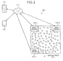
- FIG. 2 is a diagram depicting one example of the sensor network system.
- the sensor network system 200 includes base devices 102, sensor nodes 101, the position estimation apparatus 100, and a user terminal 201.
- the base devices 102, the position estimation apparatus 100, and the user terminal 201 are connected via a network NET.
- FIG. 3 is a diagram depicting an internal structure of the sensor node.
- the sensor node 101 acting as a second communication device includes a sensor 301, a wireless communication circuit 303, a microprocessor (micro control unit(MCU)) 305, and a random access memory (RAM) 306.
- the sensor node 101 includes a read only memory (ROM) 307, a non-volatile memory 308, an antenna 310, a harvester 311, and a battery 312.
- the sensor 301 detects a change of a physical quantity at the position where the sensor 301 is located.
- the sensor 301 may be a piezoelectric element that detects pressure at the position or a photoelectric element that detects light.
- the antenna 310 transmits and receives radio waves.
- the wireless communication circuit (RF) 303 outputs the received radio waves as a signal and transmits a signal via the antenna 310 as radio waves.
- the MCU 305 processes data detected by the sensor 301.
- the RAM 306 stores transient data of the processing by the MCU 305.
- the ROM 307 stores a processing program executed by the MCU 305.
- the non-volatile memory 308 stores written data even if the power supply is suspended. Elements of the sensor 301 to the non-volatile memory 308 are connected via a bus 309.
- the sensor node 101 includes the harvester 311 and the battery 312.
- the harvester 311 generates electric power based on the change of environmental conditions such as light, vibration, temperature, radio wave (received wave).
- the battery 312 stores the electric power generated by the harvester 311 and supplies each element of the sensor node 101 with the electric power.
- the sensor node 101 does not require a rechargeable battery or an external power source.
- the sensor node 101 generates necessary electric power by itself.
- FIG. 4 is a diagram depicting data stored in the ROM and the non-volatile memory.
- the ROM 307 stores, in addition to the processing program mentioned above, a sensor ID which distinguishes the sensor node 101 from the other sensor nodes.
- the non-volatile memory 308 stores the number of sensing activities and a received data information table.
- the number of sensing activities indicates how many times the sensing has been performed to acquire data. As a result, data detected by the sensor is identified.
- the received data information table possesses information concerning data received by the sensor node 101 from other sensor nodes 101.
- the received data information table includes fields of sensor ID and the number of sensing activities.
- the sensor ID field receives information concerning which sensor node has detected the data.
- the sensing activities field receives the number of sensing activities needed to detect the data received by the sensor node 101. These fields are stored as a record.
- FIG. 5 is a diagram depicting a structure of transmission data of the sensor node.
- the transmission data of the sensor node 101 includes, for example, transited-sensor information, detecting-sensor information, and sensing data.
- the transited-sensor information is information concerning sensor nodes through which data has been carried to the base device 102.
- the detecting-sensor information identifies sensing data.
- the detecting-sensor information includes the number of sensing activities and the sensor ID that indicates which sensor node has detected the data.
- FIG. 6 is a flowchart depicting a process of sensing by a sensor node.
- the sensor of the sensor node 101 performs the sensing, the sensor increments the number of sensing activities (step S601) and stores the number of sensing activities and the sensor ID in the received data information table of the non-volatile memory 308 (step S602).
- the sensor node 101 transmits the number of sensing activities and the sensor ID as the detecting-sensor information (step S603) and the process ends.
- FIG. 7 is a flowchart depicting a process of the data receiving performed by a sensor node.
- the sensor node 101 determines whether detecting-sensor information concerning the received data is present in the detecting-sensor information table of the non-volatile memory 308 (step S701). If the information is not present in the table (step S701: NO), the sensor node 101 records the detecting-sensor information into the received data information table (step S702).
- the sensor node 101 adds the sensor ID to the transited-sensor information and transfers the transited-sensor information (step S703), and the process ends. If the information is present in the table at step S701 (step S701: YES), the process ends. In this way, one sensor does not repeatedly receive the same data.
- FIG. 8 is a diagram depicting an internal structure of a base device.
- the base device 102 acting as the first communication device receives power from an external source unlike the sensor node 101.
- the base device 102 includes a central processing unit (CPU) 801 that is a higher performance processor than the MCU 305 of the sensor node 101, a high-capacity ROM 802, and a high-capacity RAM 803.
- the base device 102 also includes a non-volatile memory 809, an interface input/output (I/O) circuit 804, and a bus 805 connecting the CPU 801 to the I/O circuit 804 and the non-volatile memory 809.
- CPU central processing unit
- I/O interface input/output
- the I/O circuit 804 is connected to an antenna 806, a wireless communication circuit RF (radio frequency) 807, and a network I/F 808.
- the base device 102 communicates with an external device such as the position estimation apparatus 100 or the user terminal 201 through the network NET such as the Internet with the aid of the network I/F 808 using the TCP/IP protocol.
- FIG. 9 is a diagram depicting data stored in the ROM and the non-volatile memory of the base device.
- the ROM 802 stores a base device ID that is identification information for the base device 102.
- the non-volatile memory 809 stores, for example, a received data information table.
- the received data information table is information concerning data received from the sensor node 101.
- the received data information table includes fields of sensor ID and the number of sensing activities.
- the sensor ID field receives identification information that indicates which sensor node has detected data.
- the field of the number of sensing activities receives the number of sensing activities concerning the received data. These fields are stored as a record.
- FIG. 10 is a diagram depicting a structure of transmission data of the base device.
- the transmission data of the base device 102 includes, for example, transited-sensor information, detecting-sensor information, and sensing data.
- the transited-sensor information is used to determine through which sensor the data has been transferred before reaching the base device 102.
- the detecting-sensor information is used to identify sensing data.
- the detecting-sensor information includes the number of sensing activities and a sensor ID that indicates which sensor node has detected the data.
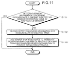
- FIG. 11 is a flowchart depicting a process performed by the base device.
- the base device determines whether detecting-sensor information concerning the received data is present in the detecting-sensor information table of the non-volatile memory 809 (step S1101). If the information is not present in the table (step S1101: NO), the base device records the detecting-sensor information in the received data information table (step S1102).
- the base device adds the base device ID to the transited-sensor information area of the received data and transfers the information to the position estimation apparatus 100 (step S1103), and the process ends.
- step S1101 if the information is present in the table (step S1101: YES), the process ends.
- FIG. 12 is a diagram depicting a hardware configuration of the position estimation apparatus.
- the position estimation apparatus 100 includes a CPU 1201, a ROM 1202, a RAM 1203, a magnetic disk drive 1204, a magnetic disk 1205, an optical disk drive 1206, and an optical disk 1207.
- the position estimation apparatus 100 also includes a network I/F 1208, an input device 1209, and an output device 1210.
- the constituent units above are connected through a bus 1200.
- the CPU 1201 governs over all control of the position estimation apparatus 100.
- the ROM 1202 stores therein various programs such as a boot program.
- the RAM 1203 is used as a working area of the CPU 1201.
- the magnetic disk drive 1204 controls the reading and writing of data with respect to the magnetic disk 305 under the control of the CPU 1201.
- the magnetic disk 1205 stores data written thereto under the control of the magnetic disk drive 1204.
- the optical disk drive 1206 controls the reading and writing of the data with respect to the optical disk 1207 under the control of the CPU 1201.
- the optical disk 1207 stores data written thereto under the control of the optical disk drive 1206.
- a computer reads data from the optical disk 1207.
- the network I/F 1208 is connected to the network NET such as a local area network (LAN), a wide area network (WAN), and the Internet through a communication line.
- the position estimation apparatus 100 is connected to other devices through the network NET.
- the network I/F 1208 functions as an interface between the position estimation apparatus 100 and the network NET and controls the input and output of data with respect to an external device.
- the network I/F 1208 may be a modem or a LAN adaptor.
- the input device 1209 is an interface for entering various data through a keyboard, a mouse, a touch panel, etc. consequent to operation by a user.
- the input device 1209 may receive an image or a moving picture from a camera.
- the input device 1209 may also receive audio data from a microphone.
- the output device 1210 is an interface for outputting data under the control of the CPU 1201.
- the output device 1210 may be a display, a printer, etc.
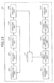
- FIG. 13 is a diagram depicting a functional configuration of the position estimation apparatus.
- the position estimation apparatus 100 includes a generating unit 1301, a selecting unit 1302, a searching unit 1303, a detecting unit 1304, and a deriving unit 1305.
- the position estimation apparatus 100 further includes an acquiring unit 1311, a first calculating unit 1312, a second calculating unit 1313, a third calculating unit 1314, and a deriving unit 1315.
- Processes concerning the generating unit 1301 to the deriving unit 1305 are performed before processes concerning the acquiring unit 1311 to the deriving unit 1315.
- the processes concerning the generating unit 1301 to the deriving unit 1305 are performed in preparation for the operation of the sensor network system 200 and the processes concerning the acquiring unit 1311 to the deriving unit 1315 are performed during the operation of the sensor network system 200.
- the processes concerning the generating unit 1301 to the deriving unit 1305 and concerning the acquiring unit 1311 to the deriving unit 1315 are coded into a position estimation program that is stored in a storage device such as the ROM 1202, the magnetic disk 1205, and the optical disk 1207.
- a storage device such as the ROM 1202, the magnetic disk 1205, and the optical disk 1207.
- Each process is implemented by the CPU 1201 reading out the position estimation program from the storage device and executing the processes.
- the CPU 1201 may obtain a program from the network NET via the network I/F 1208.
- FIG. 14 is a diagram depicting a distance corresponding to a hop.
- a distance d 3 between a central sensor node 101 under consideration and the base device 102-3 is approximately twice as much as a distance d 2 between the sensor node 101 and the base device 102-2.
- the number of hops between the sensor node 101 and the base device 102-3 is less than twice the number of hops between the sensor node 101 and the base device 102-2. Even if the communicable distance of one hop that gives a communication range is multiplied by the number of hops, the resultant product does not locate the sensor node 101. This is because sensor nodes are not necessarily uniformly distributed within a region. Sensor nodes may concentrate at a particular area.
- sensor nodes are distributed in a given region A, or mixed among substances that fill the given region A and distributed in the given region A.
- an object such as a pillar is present within the given region A
- the distances corresponding to hops (for example, d 11 to d 14 ) of a path from the sensor node to the base device 102-1 are not equal.
- the given region A takes a complex shape for an easy understanding of the distance corresponding to hops but the distances corresponding to hops are not equal irrespective of the shape of the given region A.
- a base device disposed at a corner and a base device disposed at a central part have different expected distances corresponding to a hop.
- the position estimation apparatus 100 simulates a communication path from sensor nodes within the given region A to the base devices 102.
- the position estimation apparatus 100 generates a probability distribution of hops of a path acquired by the simulation.
- the position estimation apparatus 100 handles the probability distribution as a probability distribution of estimated distances. In the end, based on the probability distribution of estimated distances and the number of hops known from actual communications, a more accurate probability distribution is obtained.
- Example of input data is as below.
- the communicable distance by one hop may be expressed with a probability distribution f(r) when the communicable distance is affected by surrounding conditions or the antenna has directivity.
- the generating unit 1301 randomly generates position information that indicates positions of sensor nodes within the given region A.
- a designer of the sensor network system 200 may decide how many sensor nodes are generated.
- the selecting unit 1302 selects one sensor node from among multiple sensor nodes.
- the sensor node may be selected from any place in the region A or from within a predetermined area.
- the searching unit 1303 searches for a communication path from the selected sensor node to a base device based on the communicable distance covered by one hop, each time the position information is generated by the generating unit 1301.
- FIG. 15 is a diagram depicting a searching process (part 1).
- a sensor node 101-45 is selected.
- a log file is a table that stores a communication path. The log file includes fields of ID and transited sensor.
- FIG. 16 is a diagram depicting a searching process (part 2). Sensor nodes present in a communicable range of one hop with the selected sensor node at the center are searched for. In FIG. 16 , sensor nodes 101-4, 101, 14, 33, and 50 are retrieved. IDs of 4, 101, 14, and 33, 50 are registered in the ID field of the log file.
- FIG. 17 is a diagram depicting a searching process (part 3). Sensor nodes present in a communicable range of one hop with each retrieved sensor node at the center are searched for. In this way, a path from the selected sensor node to one of the base devices is searched for. For example, the position of the sensor node 101-21 is within the communicable range by one hop from the position of the sensor node 101-50. ID 21 is registered in the ID field of the log file and IDs 45, 50, and 21 are registered in the transited sensor field.
- FIG. 18 is a diagram depicting a retrieved communication path. In FIG. 18 , the communication path from the selected sensor node to one of the base devices is depicted.
- FIG. 19 is a diagram depicting an example of distance calculation.
- the detecting unit 1304 measures, for each base device, the distances corresponding to each hop of the retrieved communication path based on the position information of a base device and the position information of the selected sensor node. For example, the distance l 11 corresponding to the space between the base device 102-1 and the sensor node 101-44, the distance l 12 corresponding to the space between the sensor node 101-44 and the sensor node 101-21, the distance l 13 corresponding to the space between the sensor node 101-21 and the sensor node 101-50, and the distance l 14 corresponding to the space between the sensor node 101-50 and the sensor node 101-45 are measured.
- the deriving unit 1305 derives frequencies of distances for each base device.
- the deriving unit 1305 may derive a probability distribution based on a distribution of distances.
- the deriving unit 1305 stores the data in the storage device 110 as depicted in FIG. 1 .
- the deriving unit 1305 derives the frequencies of distances corresponding to each hop for each base device 102.
- the deriving unit 1305 may derive a probability distribution based on the distribution of distances.
- the deriving unit 1305 stores, as the distribution of estimated distances corresponding to each hop, the probability distribution derived from the frequency of distances.
- the deriving unit 1305 derives a probability distribution of one-hop distances for each base device 102.
- K ij ⁇ k
- the deriving unit 1305 acquires a distribution of l ij by substituting the average and the variance into Equation (3) below.
- l ij 1 2 ⁇ ⁇ ⁇ ⁇ ij 2 ⁇ exp - l ij - ⁇ ij 2 2 ⁇ ⁇ ij
- FIG. 20 is a diagram depicting probability distributions of estimated distances stored in the storage device.
- the storage device 110 stores a probability distribution depicting a probability based on the frequencies of each hop for each base device 102.
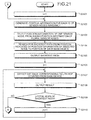
- FIG. 21 and FIG. 22 are flowcharts depicting an example of a process of generating a distribution performed by the position estimation apparatus.
- the position estimation apparatus 100 selects from position information of plural sensor nodes, position information of one sensor node 101 (step S2103).
- the position estimation apparatus 100 may randomly select one sensor node or select one sensor node from within a given area.
- the position estimation apparatus 100 searches for the shortest path from the selected sensor node 101 to a base device 102, for each base device based on the communicable distance by one hop (step S2104).
- the position estimation apparatus 100 outputs the shortest path (step S2105).
- the elements of the generating unit 1301 to the deriving unit 1305 may be performed by a computer other than the position estimation apparatus 100.
- the computer other than the position estimation apparatus 100 conducts the functions of the elements above, the computer stores the generated distributions in a storage device that is accessible by the position estimation apparatus 100.
- FIG. 23 is a diagram depicting a hops accumulating table.
- the position estimation apparatus 100 communicating with each base device 102, acquires information concerning how many hops are needed to reach a base device 102 from a sensor node and creates the hops accumulating table 2300.
- the hops accumulating table 2300 includes fields of sensor ID, the least hops to the base device 1, the least hops to the base device 2, and the least hops to the base device 3.
- the fields with information registered therein are stored as records (for example 2301-1, 2301-2).
- the hops accumulating table 2300 is implemented by a storage device such as the RAM 1203, the magnetic disk 1205, and the optical disk 1207. Identification information of each sensor node is registered in the field of sensor ID.
- the least number of hops that data of the sensor node indicated by the sensor ID in the field needs to reach the base device 102-1 is registered in the field of the least hops to the base device 1.
- the least number of hops that data of the sensor node indicated by the sensor ID in the field needs to reach the base device 102-2 is registered in the field of the least hops to the base device 2.
- the least number of hops that data of the sensor node indicated by the sensor ID in the field needs to reach the base device 102-3 is registered in the field of the least hops to the base device 3.
- FIG. 24 is a diagram depicting a one-hop range sensor table.
- the position estimation apparatus 100 communicating with base devices, acquires information concerning which sensor node the sensor node under consideration can communicate with by one hop and creates a one-hop range sensor table 2400.
- the one-hop range sensor table 2400 includes, for example, fields of sensor ID and one-hop range sensor ID.
- the fields with information registered therein are stored as records (for example, 2401-1).
- the one-hop range sensor table 2400 may be implemented by a storage device such as the RAM 1203, the magnetic disk 1205, and the optical disk 1207. Identification information of each sensor node is registered in the field of sensor ID. Identification information of sensor nodes that the sensor node indicated by the identification information in the sensor ID field can communicate with by one hop is registered in the field of the one-hop range sensor ID.
- the acquiring unit 1311 acquires, based on the communication between the sensor node under consideration and a base device, the number of hops that data from the sensor node under consideration requires to reach a base device. For example, the acquiring unit 1311 acquires the least number of hops to each base device from the hops accumulating table 2300, based on the ID of the sensor node under consideration.
- the first calculating unit 1312 calculates a distribution of estimated distances under the least hops between sensor nodes and the base devices based on the least hops and the distributions of estimated distances stored in the storage device 110.
- the first calculating unit 1312 also calculates a distribution of estimated distances under the least hops between sensor nodes and the base devices based on the sum of distributions of estimated one-hop distances with the total hops ⁇ the least hops.
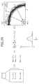
- FIG. 25 is a diagram depicting a distribution of estimated position under the least hops.
- the least hops are denoted by h.
- the sensor node under consideration is labeled with s.
- the first calculating unit 1312 acquires N( ⁇ 21 , ⁇ 2 21 ) to N ( ⁇ 2h , ⁇ 2 2h ) from the storage device 110.
- the first calculating unit 1312 yields the sum of N( ⁇ 21 , ⁇ 2 21 ) to N ( ⁇ 2h , ( ⁇ 2 2h ).
- a distribution obtained by the summation is a distribution of estimated distances r h under the least hops.
- the second calculating unit 1313 calculates, for each base device, a distribution of estimated positions within the region A, based on the distribution of estimated distances, the information concerning the range of the region A, and the information concerning the position of the base device.
- dark color indicates a higher probability of the presence of a sensor node and fainter color indicates a lower probability.
- the second calculating unit 1313 calculates a distribution of estimated positions of the sensor node under consideration with a polar coordinate system (r, ⁇ ) based on the distances from the base device 102-p.
- p represents identification information of each base device.
- ⁇ ), a probability distribution of r with ⁇ fixed, is represented by Equations (4) to (6) below.
- FIG. 26 is a diagram depicting a range of r and ⁇ .
- f s,p (r, ⁇ ) is derived according to Equation (11) below and thus is represented by Equations (12) to (14) below.
- the second calculating unit 1313 transforms the distribution of estimated position of a sensor node 101-s f s,p (r
- Equation (12) can be expressed as Equation (17) below under the orthogonal coordinate system.
- the probability density function of Equations (13) and (14) is expressed as Equations (18) and (19) below under the orthogonal coordinate system.
- the second calculating unit 1313 calculates the sum of distributions of estimated positions, based on Equations (17) to (19).
- the deriving unit 1315 derives an estimated position of the sensor node under consideration based on the index calculated by the third calculating unit 1314. Two examples of the derivation of an estimated position are introduced below.
- FIG. 28 is a diagram depicting a first example of the derivation of an estimated position.
- a distribution in FIG. 28 illustrates an index that indicates where a sensor node is likely to be present within the region A. Darker color indicates a higher probability of the presence of the sensor node under consideration. Fainter color indicates a lower probability of the presence of the sensor node under consideration.
- the deriving unit 1315 derives an estimated position where the index takes the maximum.
- FIG. 29 is a diagram depicting a second example of the derivation of an estimated position.
- indexes for two sensor nodes have been calculated. It is also assumed that the two sensor nodes can communicate with each other by one hop.
- the deriving unit 1315 specifies, based on the one-hop range sensor table 2400, two sensor nodes that can communicate with each other by one hop.
- the deriving unit 1315 derives estimated positions of two sensor nodes that can communicate with each other by one hop.
- the deriving unit 1315 derives, based on the two indexes, estimated positions of two sensor nodes having a distance therebetween that is less than a threshold.
- the estimated position of a first sensor node is expressed as (x 1 , y 1 ) and the estimated position of a second sensor node is expressed as (x 2 , y 2 ).
- the deriving unit 1315 determines whether the distance between the two sensor nodes is less than the threshold r 0 .
- the threshold may be the smallest distance among distances where data cannot surely be received between sensor nodes.
- the threshold is stored beforehand by a designer or developer of the sensor network system 200 in a storage device such as the RAM 1203, the magnetic disk 1205, and the optical disk 1207.
- the estimated positions p 0-1 and p 0-2 have high probabilities while the distance d 00 between the positions p 0-1 and p 0-2 is at least the threshold r 0 .
- the positions p 0-1 and p 0-2 are not regarded as the estimated positions.
- the distance d 01 between the estimated positions p 1-1 and p 1-2 is less than the threshold r 0 .
- the positions p 1-1 and p 1-2 are regarded as the estimated positions of the sensor nodes.
- the deriving unit 1315 derives estimated positions of the two sensor nodes where the maximal probabilities are obtained with the distance therebetween being less than the threshold.
- the deriving unit 1315 derives estimated positions of some sensor nodes simultaneously.
- the term of some sensor nodes indicates sensor nodes whose indexes have been calculated by the third calculating unit 1314.
- the deriving unit 1315 derives estimated positions of the sensor nodes based the indexes.
- the deriving unit 1315 solves (a) of Equation (21) below so that (b) of Equation (21) is satisfied.
- A is a set of pairs of sensor IDs that are obtained from the one-hop range sensor table 2400 and indicate a pair of sensor nodes within a communication range covered by one hop.
- Equation (21) the method of Lagrange multipliers may be used.
- the deriving unit 1315 solves the system of Equations (22), (23), (24), and (25) below.
- the deriving unit 1315 may give to x s and y s discrete values such as 1, ..., 100 and solve Equation (21). In this way, the number of combinations of all estimated positions becomes finite and a solution of Equation (21) can be obtained even if estimated positions are less accurate.
- FIG. 30 is a flowchart depicting the first example of the position estimation process performed by the position estimation apparatus.
- the position estimation apparatus 100 selects an ID of a target sensor node from the hops accumulating table 2300 (step S3001).
- the position estimation apparatus 100 acquires the number of hops between the target sensor node and a base device 102-p based on the ID (step S3004).
- the position estimation apparatus 100 acquires from the storage device 110, distributions of estimated distances corresponding to a hop (step S3005) and calculates a distribution of estimated distances amounting to the hops (step S3006).
- the process returns to step S3003.
- the position estimation apparatus 100 calculates a distribution of estimated positions of the target sensor node based on the sum of the distributions of estimated positions calculated for the base devices (step S3009).
- the position estimation apparatus 100 derives an estimated position of the target node where the probability becomes maximal, based on the distribution of estimated positions of the target sensor node (step S3010).
- the position estimation apparatus 100 associates and outputs the estimated position and the ID of the target sensor node (step S3011) and the process ends.
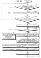
- FIG. 31 and FIG. 32 are flowcharts depicting the second example of the position estimation process performed by the position estimation apparatus.
- the position estimation apparatus 100 determines, based on the hops accumulating table 2300, whether there is an ID of a sensor node that has not yet been selected (step S3101). If there is an ID of a sensor node yet to be selected (step S3101: YES), the position estimation apparatus 100 selects an ID of a sensor node yet to be selected (step S3102). It is assumed that the selected ID indicates a target sensor node.
- the position estimation apparatus 100 checks whether the least hops of the target node have been registered in the hops accumulating table 2300 (step S3103). It is checked whether the least hops to all base devices have been registered.
- the position estimation apparatus 100 acquires, from the storage device 110, a distribution of estimated distances corresponding to the acquired total hops (step S3107) and calculates based on the acquired distributions, a distribution of estimated distances amounting to the total hops acquired by the communication with the base device (step S3108).
- step S3105 If “p ⁇ the number of base devices" is not true (step S3105: NO), the position estimation apparatus 100 calculates a distribution of estimated positions of the target sensor node based on the sum of the distributions for the base devices 102 (step S3111) and the process returns to step S3101.
- the position estimation apparatus 100 acquires from the one-hop range sensor table 2400, a pair of sensor nodes that are in a communicable range covered by one hop (step S3201).
- the position estimation apparatus 100 derives, from the distributions of estimated distances, estimated positions such that the distance between the pair is less than the threshold (step S3202).
- the position estimation apparatus 100 determines whether positions have been estimated (step S3203). If the positions have been estimated (step S3203: YES), the process goes to S3206. If the positions could not be estimated (step S3203: NO), the position estimation apparatus 100 replaces the information concerning the range of the region A with discrete values (step S3204). As a result, the number of pairs of estimated positions becomes finite.
- the position estimation apparatus 100 derives, based on the discrete values, estimated positions such that the distance between the pair is less than the threshold (step S3205).
- the position estimation apparatus 100 derives estimated positions where the probability takes the maximum value (step S3206) and the process ends.
- the position estimation apparatus 100 stores the result in a storage device such as the RAM 1203, the magnetic disk 1204, and the optical disk 1206 or outputs the result via the output device 1210.
- the position estimation apparatus derives a distribution of estimated positions of a target sensor node from the distribution of estimated distances and the number of hops between a base device and the target sensor node in actual communication. As a result, the accuracy of estimating the position of the target sensor node improves.
- the position estimation apparatus can estimate the position of the target sensor node even if a sensor node does not detect the strength or delay of radio waves. Therefore, load against a sensor node is reduced.
- Sensor nodes may be not uniformly disposed in a region because of, for example the shape of the region. Thus, distances corresponding to each hop along the path between a sensor node and a base device are not equal. Distributions of estimated distances corresponding to each hop along the path are stored in the storage device. The position estimation apparatus calculates, for each base device, a distribution of estimated distances corresponding to the total hops based on the sum of the distribution of estimated distances corresponding to each hop. In this way, the accuracy of estimating the position of the target sensor node improves.
- the position estimation apparatus specifies a position where the target sensor node is most likely to be present based on the distribution of estimated positions. As a result, the position of the target sensor node having the highest probability can be specified. Therefore, the accuracy of the position estimation improves.
- the position estimation apparatus also estimates positions such that the distance of two estimated positions is less than a threshold, based on the distributions of estimated positions of a first target sensor node and a second target sensor node within a communication-cable range by one hop. With the relative positional relation between two sensor nodes, the positions of sensor nodes can be estimated more accurately.
- the position estimation apparatus also specifies the positions of sensor nodes requiring that the distance between two sensor nodes in a communicable range by one hop be less than the threshold. In this way, the position of a sensor node can be estimated more accurately.
- the position estimation apparatus randomly generates a given number of times, information concerning the positions of sensor nodes within a given region and searches for a path from a selected position to a base device.
- the position estimation apparatus detects hops along the path and derives frequencies of distances corresponding to each hop.
- a distribution of estimated distances is a frequency of distances.
- sensor nodes may be disposed randomly within a given region depending on the shape of the given region.
- distances corresponding to each hop along the path between a sensor node and a base device are not equal.
- the position estimation apparatus derives frequencies of each distance corresponding to each hop.
- the distribution of estimated distances stored in the storage device is a distribution representing a frequency of distances. As a result, a distribution of distances corresponding to each hop can be obtained even if the exact position of sensor nodes is unknown. Therefore, the position of the target sensor node can be estimated more accurately.
- the position estimation method in the present embodiments can be implemented by a computer, such as a personal computer and a workstation, executing a program that is prepared in advance.
- the position estimation program is recorded on a computer-readable recording medium such as a hard disk, a flexible disk, a CD-ROM, and a DVD, and is executed by being read out from the recording medium by a computer.
- the program can be distributed through a network such as the Internet.
Landscapes
- Engineering & Computer Science (AREA)
- Physics & Mathematics (AREA)
- General Physics & Mathematics (AREA)
- Radar, Positioning & Navigation (AREA)
- Remote Sensing (AREA)
- Computer Networks & Wireless Communication (AREA)
- Signal Processing (AREA)
- Probability & Statistics with Applications (AREA)
- Mobile Radio Communication Systems (AREA)
- Position Fixing By Use Of Radio Waves (AREA)
Abstract
Description
- The embodiments discussed herein are related to a position estimation method, a system, and a position estimation apparatus.
- A method is known that when the positions of communication devices are unknown, a target communication device is located by finding a communication path from the target communication device to a communication device whose position is known. For example, the position of a node is estimated based on the distance between adjacent nodes on the communication path, the distance being measured with the strength or delay of radio waves (see
Patent Document 1 below). Alternatively, communication paths up to nodes whose positions are known are specified and an approximate position of a node is estimated based on the number of hops over each communication path, a communication-cable distance by one hop, and positional information of the nodes whose positions are known (seePatent Document 2 below). -
- Patent Document 1: Japanese Laid-open Patent Publication No.
2007-221541 - Patent Document 2: Japanese Laid-open Patent Publication No.
2006-229845 - However, there are cases where the position of a communication device cannot be estimated accurately due to the communication environment or the positioning of communication devices.
- In one aspect of the present invention, an object is to provide a position estimation method, a system, and a position estimation apparatus that can improve accuracy when estimating the position of a communication device.
- According to one aspect of the present invention, a position estimation method is performed by a computer that accesses a storage device storing a probability distribution of distances corresponding to a hop along a path between a first communication device and a second communication device within a region. The method includes acquiring total hops needed for data of the second communication device to reach the first communication device based on analysis of communications between the first communication device and the second communication device; calculating a probability distribution of distances corresponding to the total hops based on the total hops and the probability distribution of a hop stored in the storage device; calculating a probability distribution of positions within the region based on the probability distribution of distances, information concerning a range of the region, and information concerning a position of the first communication device; calculating, based on a sum of the probability distribution of positions, an index that indicates a probability of presence of the second communication device; and deriving an estimated position of the second communication device from the index.
- According to an aspect of the embodiments, the accuracy of estimation of the position of a communication device is improved.
-
-
FIG. 1 is a diagram depicting an example of operation of the embodiments; -
FIG. 2 is a diagram depicting one example of a sensor network system; -
FIG. 3 is a diagram depicting an internal structure of a sensor node; -
FIG. 4 is a diagram depicting data stored in a ROM and a non-volatile memory; -
FIG. 5 is a diagram depicting a structure of transmission data of the sensor node; -
FIG. 6 is a flowchart depicting a process of sensing performed by a sensor node; -
FIG. 7 is a flowchart depicting a process of data receiving performed by a sensor node; -
FIG. 8 is a diagram depicting an internal structure of a base device; -
FIG. 9 is a diagram depicting data stored in a ROM and a non-volatile memory of the base device; -
FIG. 10 is a diagram depicting a structure of transmission data of the base device; -
FIG. 11 is a flowchart depicting a process performed by the base device; -
FIG. 12 is a diagram depicting a hardware configuration of a position estimation apparatus; -
FIG. 13 is a diagram depicting a functional configuration of the position estimation apparatus; -
FIG. 14 is a diagram depicting a distance corresponding to a hop; -
FIG. 15 is a diagram depicting a searching process (part 1); -
FIG. 16 is a diagram depicting a searching process (part 2); -
FIG. 17 is a diagram depicting a searching process (part 3); -
FIG. 18 is a diagram depicting a retrieved communication path; -
FIG. 19 is a diagram depicting an example of distance calculation; -
FIG. 20 is a diagram depicting probability distributions of estimated distances stored in a storage device; -
FIG. 21 andFIG. 22 are flowcharts depicting an example of process of generating a distribution performed by the position estimation apparatus; -
FIG. 23 is a diagram depicting a hops accumulating table; -
FIG. 24 is a diagram depicting a one-hop range sensor table; -
FIG. 25 is a diagram depicting a distribution of estimated positions under the least hops; -
FIG. 26 is a diagram depicting a range of r and θ; -
FIG. 27 is a diagram depicting f(θ); -
FIG. 28 is a diagram depicting a first example of the derivation of an estimated position; -
FIG. 29 is a diagram depicting a second example of the derivation of an estimated position; -
FIG. 30 is a flowchart depicting a first example of the position estimation process performed by the position estimation apparatus; and -
FIG. 31 andFIG. 32 are flowcharts depicting a second example of the position estimation process performed by the position estimation apparatus. - With reference to the accompanying drawings, preferred embodiments of a position estimation method, system, and position estimation apparatus are described. A sensor network of the embodiments includes many sensors disposed within a given region. Each sensor detects and wirelessly transmits information. A base device which wirelessly communicates with sensors in the given region collects the information. The given region is, for example, a region filled with materials such as concrete, soil, water, and air. The given region may be a vacuum space like a cosmic space. A node is defined as a device that has a sensor and a processor that processes data detected by the sensor. For example, hundreds to tens of thousands of sensor nodes are disposed in the given region.
-
FIG. 1 is a diagram depicting an example of operation of the embodiments. Aposition estimation apparatus 100 accesses astorage device 110 and is a computer that has a function of estimating positions of sensor nodes 101-1 to 101-n, which are second communication devices, within a given region A. Eachsensor node 101 is disposed in the given region A by, for example, being distributed in the given region A or mixed with substances that fill the given region A. Thus, the position of eachsensor node 101 is unknown. - Base devices 102-1 to 102-m, acting as first communication devices, are disposed at given positions (in the case of
FIG. 1 , m=3). The given positions are, for example, those determined by a user or a designer of the sensor network. The given positions may be within the given region A. Thebase devices 102 may be arranged surrounding the given region A. Thebase devices 102 do not occupy the same position. - According to wireless communication of the embodiments, the
sensor nodes 101 communicate each other performing multi-hop communication. For example, eachsensor node 101 directly transmits data to or receives data from abase device 102. When asensor node 101 is so far from thebase device 102 that communication cannot be established, eachsensor node 101 transmits a radio signal to an adjacent data processing device and relays data to the adjacent data processing device. For this reason, eachsensor node 101 has a wireless communication circuit with a small output power sufficient for communication with an adjacent sensor node, thereby reducing the size and the power consumption of thesensor node 101. - A
storage device 110 stores, for each base device, a probability distribution of estimated distances corresponding to a hop of a path of wireless communication between eachsensor node 101 and thebase device 102. For example, a probability distribution is illustrated with the horizontal axis being the distance that data approaches the base device by one hop and the vertical axis being the probability or frequencies of the distance generated by simulation. A detailed description of the simulation will be given later. InFIG. 1 , the probability distribution of estimated distances for a base device 102-1 is called db1, for a base device 102-2 db2, and for a base device 102-3 db3. - The
position estimation apparatus 100 acquires, for each base device, total hops, the number of hops that data from asensor node 101 under consideration need to pass through to reach thebase device 102. The total hops indicate how many times data are relayed. - The
position estimation apparatus 100 calculates, for each base device, a probability distribution of estimated distances corresponding to the total hops between a base device and a sensor node under consideration based on the total hops and the probability distributions of estimated distances concerning thebase device 102 stored in thestorage device 110. - The
position estimation apparatus 100 calculates, for eachbase device 102, a probability distribution of estimated positions within the given region A based on the probability distribution of estimated distances, information concerning the range of the given region A, and positional information of thebase devices 102.FIG. 1 depicts probability distributions of estimated positions within the given region A for eachbase device 102. A probability distribution of estimated positions within the given region A for the base device 102-1 is called pdb1, for the base device 102-2 pdb2, and for the base device 102-3 pdb3. Darker color indicates higher probability and fainter color indicates lower probability. - Based on the sum of the probability distributions of estimated positions, the
position estimation apparatus 100 calculates an index that indicates the probability of the position of asensor node 101 under consideration. On the right side ofFIG. 1 , the index within the given region A is depicted as the probability distribution pdb10. Darker color indicates higher probability and fainter color indicates lower probability. An area in a central part ofFIG. 1 where three probability distributions overlap corresponds to a darker area on a right side ofFIG. 1 . - The
position estimation apparatus 100 derives an estimated position of asensor node 101 under consideration from the index. The largest index may be regarded as the estimated position of thesensor node 101. - According to
FIG. 1 , the accuracy of position estimation of a sensor node is improved. -
FIG. 2 is a diagram depicting one example of the sensor network system. Thesensor network system 200 includesbase devices 102,sensor nodes 101, theposition estimation apparatus 100, and auser terminal 201. Thebase devices 102, theposition estimation apparatus 100, and theuser terminal 201 are connected via a network NET. -
FIG. 3 is a diagram depicting an internal structure of the sensor node. Thesensor node 101 acting as a second communication device includes asensor 301, awireless communication circuit 303, a microprocessor (micro control unit(MCU)) 305, and a random access memory (RAM) 306. Thesensor node 101 includes a read only memory (ROM) 307, anon-volatile memory 308, anantenna 310, aharvester 311, and abattery 312. - The
sensor 301 detects a change of a physical quantity at the position where thesensor 301 is located. Thesensor 301 may be a piezoelectric element that detects pressure at the position or a photoelectric element that detects light. Theantenna 310 transmits and receives radio waves. The wireless communication circuit (RF) 303 outputs the received radio waves as a signal and transmits a signal via theantenna 310 as radio waves. - The
MCU 305 processes data detected by thesensor 301. TheRAM 306 stores transient data of the processing by theMCU 305. TheROM 307 stores a processing program executed by theMCU 305. Thenon-volatile memory 308 stores written data even if the power supply is suspended. Elements of thesensor 301 to thenon-volatile memory 308 are connected via abus 309. - The
sensor node 101 includes theharvester 311 and thebattery 312. Theharvester 311 generates electric power based on the change of environmental conditions such as light, vibration, temperature, radio wave (received wave). Thebattery 312 stores the electric power generated by theharvester 311 and supplies each element of thesensor node 101 with the electric power. Thesensor node 101 does not require a rechargeable battery or an external power source. Thesensor node 101 generates necessary electric power by itself. -
FIG. 4 is a diagram depicting data stored in the ROM and the non-volatile memory. TheROM 307 stores, in addition to the processing program mentioned above, a sensor ID which distinguishes thesensor node 101 from the other sensor nodes. - The
non-volatile memory 308 stores the number of sensing activities and a received data information table. The number of sensing activities indicates how many times the sensing has been performed to acquire data. As a result, data detected by the sensor is identified. - The received data information table possesses information concerning data received by the
sensor node 101 fromother sensor nodes 101. For example, the received data information table includes fields of sensor ID and the number of sensing activities. The sensor ID field receives information concerning which sensor node has detected the data. The sensing activities field receives the number of sensing activities needed to detect the data received by thesensor node 101. These fields are stored as a record. -
FIG. 5 is a diagram depicting a structure of transmission data of the sensor node. The transmission data of thesensor node 101 includes, for example, transited-sensor information, detecting-sensor information, and sensing data. The transited-sensor information is information concerning sensor nodes through which data has been carried to thebase device 102. The detecting-sensor information identifies sensing data. The detecting-sensor information includes the number of sensing activities and the sensor ID that indicates which sensor node has detected the data. -
FIG. 6 is a flowchart depicting a process of sensing by a sensor node. When the sensor of thesensor node 101 performs the sensing, the sensor increments the number of sensing activities (step S601) and stores the number of sensing activities and the sensor ID in the received data information table of the non-volatile memory 308 (step S602). Thesensor node 101 transmits the number of sensing activities and the sensor ID as the detecting-sensor information (step S603) and the process ends. -
FIG. 7 is a flowchart depicting a process of the data receiving performed by a sensor node. Thesensor node 101 determines whether detecting-sensor information concerning the received data is present in the detecting-sensor information table of the non-volatile memory 308 (step S701). If the information is not present in the table (step S701: NO), thesensor node 101 records the detecting-sensor information into the received data information table (step S702). - The
sensor node 101 adds the sensor ID to the transited-sensor information and transfers the transited-sensor information (step S703), and the process ends. If the information is present in the table at step S701 (step S701: YES), the process ends. In this way, one sensor does not repeatedly receive the same data. -
FIG. 8 is a diagram depicting an internal structure of a base device. Thebase device 102 acting as the first communication device receives power from an external source unlike thesensor node 101. Thebase device 102 includes a central processing unit (CPU) 801 that is a higher performance processor than theMCU 305 of thesensor node 101, a high-capacity ROM 802, and a high-capacity RAM 803. Thebase device 102 also includes anon-volatile memory 809, an interface input/output (I/O)circuit 804, and abus 805 connecting theCPU 801 to the I/O circuit 804 and thenon-volatile memory 809. - The I/
O circuit 804 is connected to anantenna 806, a wireless communication circuit RF (radio frequency) 807, and a network I/F 808. Thebase device 102 communicates with an external device such as theposition estimation apparatus 100 or theuser terminal 201 through the network NET such as the Internet with the aid of the network I/F 808 using the TCP/IP protocol. -
FIG. 9 is a diagram depicting data stored in the ROM and the non-volatile memory of the base device. In addition to a processing program concerning the process performed by thebase device 102, theROM 802 stores a base device ID that is identification information for thebase device 102. - The
non-volatile memory 809 stores, for example, a received data information table. The received data information table is information concerning data received from thesensor node 101. For example, the received data information table includes fields of sensor ID and the number of sensing activities. The sensor ID field receives identification information that indicates which sensor node has detected data. The field of the number of sensing activities receives the number of sensing activities concerning the received data. These fields are stored as a record. -
FIG. 10 is a diagram depicting a structure of transmission data of the base device. The transmission data of thebase device 102 includes, for example, transited-sensor information, detecting-sensor information, and sensing data. The transited-sensor information is used to determine through which sensor the data has been transferred before reaching thebase device 102. The detecting-sensor information is used to identify sensing data. The detecting-sensor information includes the number of sensing activities and a sensor ID that indicates which sensor node has detected the data. -
FIG. 11 is a flowchart depicting a process performed by the base device. The base device determines whether detecting-sensor information concerning the received data is present in the detecting-sensor information table of the non-volatile memory 809 (step S1101). If the information is not present in the table (step S1101: NO), the base device records the detecting-sensor information in the received data information table (step S1102). - The base device adds the base device ID to the transited-sensor information area of the received data and transfers the information to the position estimation apparatus 100 (step S1103), and the process ends. At step S1101, if the information is present in the table (step S1101: YES), the process ends.
-
FIG. 12 is a diagram depicting a hardware configuration of the position estimation apparatus. InFIG. 12 , theposition estimation apparatus 100 includes aCPU 1201, aROM 1202, aRAM 1203, amagnetic disk drive 1204, amagnetic disk 1205, anoptical disk drive 1206, and anoptical disk 1207. Theposition estimation apparatus 100 also includes a network I/F 1208, aninput device 1209, and anoutput device 1210. The constituent units above are connected through abus 1200. - The
CPU 1201 governs over all control of theposition estimation apparatus 100. TheROM 1202 stores therein various programs such as a boot program. TheRAM 1203 is used as a working area of theCPU 1201. Themagnetic disk drive 1204 controls the reading and writing of data with respect to themagnetic disk 305 under the control of theCPU 1201. Themagnetic disk 1205 stores data written thereto under the control of themagnetic disk drive 1204. - The
optical disk drive 1206 controls the reading and writing of the data with respect to theoptical disk 1207 under the control of theCPU 1201. Theoptical disk 1207 stores data written thereto under the control of theoptical disk drive 1206. A computer reads data from theoptical disk 1207. - The network I/
F 1208 is connected to the network NET such as a local area network (LAN), a wide area network (WAN), and the Internet through a communication line. Theposition estimation apparatus 100 is connected to other devices through the network NET. The network I/F 1208 functions as an interface between theposition estimation apparatus 100 and the network NET and controls the input and output of data with respect to an external device. The network I/F 1208 may be a modem or a LAN adaptor. - The
input device 1209 is an interface for entering various data through a keyboard, a mouse, a touch panel, etc. consequent to operation by a user. Theinput device 1209 may receive an image or a moving picture from a camera. Theinput device 1209 may also receive audio data from a microphone. Theoutput device 1210 is an interface for outputting data under the control of theCPU 1201. Theoutput device 1210 may be a display, a printer, etc. -
FIG. 13 is a diagram depicting a functional configuration of the position estimation apparatus. Theposition estimation apparatus 100 includes agenerating unit 1301, a selectingunit 1302, asearching unit 1303, a detectingunit 1304, and aderiving unit 1305. Theposition estimation apparatus 100 further includes an acquiringunit 1311, afirst calculating unit 1312, asecond calculating unit 1313, athird calculating unit 1314, and aderiving unit 1315. Processes concerning thegenerating unit 1301 to thederiving unit 1305 are performed before processes concerning the acquiringunit 1311 to thederiving unit 1315. For example, the processes concerning thegenerating unit 1301 to thederiving unit 1305 are performed in preparation for the operation of thesensor network system 200 and the processes concerning the acquiringunit 1311 to thederiving unit 1315 are performed during the operation of thesensor network system 200. - The processes concerning the
generating unit 1301 to thederiving unit 1305 and concerning the acquiringunit 1311 to thederiving unit 1315 are coded into a position estimation program that is stored in a storage device such as theROM 1202, themagnetic disk 1205, and theoptical disk 1207. Each process is implemented by theCPU 1201 reading out the position estimation program from the storage device and executing the processes. TheCPU 1201 may obtain a program from the network NET via the network I/F 1208. - As a preparation process for the operation of the
sensor network system 200, the generation of a probability distribution of estimated distances by thegenerating unit 1301 to thederiving unit 1305 is explained. In this example, distances corresponding to hops are not equal. -
FIG. 14 is a diagram depicting a distance corresponding to a hop. A distance d3 between acentral sensor node 101 under consideration and the base device 102-3 is approximately twice as much as a distance d2 between thesensor node 101 and the base device 102-2. The number of hops between thesensor node 101 and the base device 102-3 is less than twice the number of hops between thesensor node 101 and the base device 102-2. Even if the communicable distance of one hop that gives a communication range is multiplied by the number of hops, the resultant product does not locate thesensor node 101. This is because sensor nodes are not necessarily uniformly distributed within a region. Sensor nodes may concentrate at a particular area. As mentioned above, sensor nodes are distributed in a given region A, or mixed among substances that fill the given region A and distributed in the given region A. When an object such as a pillar is present within the given region A, there is an area void of a sensor node. As a result, the distances corresponding to hops (for example, d11 to d14) of a path from the sensor node to the base device 102-1 are not equal. InFIG. 14 , the given region A takes a complex shape for an easy understanding of the distance corresponding to hops but the distances corresponding to hops are not equal irrespective of the shape of the given region A. For example, in a square region, a base device disposed at a corner and a base device disposed at a central part have different expected distances corresponding to a hop. - In this embodiment, the
position estimation apparatus 100 simulates a communication path from sensor nodes within the given region A to thebase devices 102. Theposition estimation apparatus 100 generates a probability distribution of hops of a path acquired by the simulation. Theposition estimation apparatus 100 handles the probability distribution as a probability distribution of estimated distances. In the end, based on the probability distribution of estimated distances and the number of hops known from actual communications, a more accurate probability distribution is obtained. - Example of input data is as below.
- Position of base device 102-1: (0, 100)
- Position of base device 102-2: (0, 0)
- Position of base device 102-3: (100, 100)
- Range of region A: {(x, y) | 0 ≤x≤100, 0 ≤y≤100}
- The number of sensor nodes: n
- Communicable distance by one hop: r [m]
- The communicable distance by one hop may be expressed with a probability distribution f(r) when the communicable distance is affected by surrounding conditions or the antenna has directivity.
- The
generating unit 1301 randomly generates position information that indicates positions of sensor nodes within the given region A. A designer of thesensor network system 200 may decide how many sensor nodes are generated. - The selecting
unit 1302 selects one sensor node from among multiple sensor nodes. The sensor node may be selected from any place in the region A or from within a predetermined area. - The searching
unit 1303 searches for a communication path from the selected sensor node to a base device based on the communicable distance covered by one hop, each time the position information is generated by thegenerating unit 1301. -
FIG. 15 is a diagram depicting a searching process (part 1). InFIG. 15 , a sensor node 101-45 is selected. A log file is a table that stores a communication path. The log file includes fields of ID and transited sensor. -
FIG. 16 is a diagram depicting a searching process (part 2). Sensor nodes present in a communicable range of one hop with the selected sensor node at the center are searched for. InFIG. 16 , sensor nodes 101-4, 101, 14, 33, and 50 are retrieved. IDs of 4, 101, 14, and 33, 50 are registered in the ID field of the log file. -
FIG. 17 is a diagram depicting a searching process (part 3). Sensor nodes present in a communicable range of one hop with each retrieved sensor node at the center are searched for. In this way, a path from the selected sensor node to one of the base devices is searched for. For example, the position of the sensor node 101-21 is within the communicable range by one hop from the position of the sensor node 101-50.ID 21 is registered in the ID field of the log file andIDs -
FIG. 18 is a diagram depicting a retrieved communication path. InFIG. 18 , the communication path from the selected sensor node to one of the base devices is depicted. -
FIG. 19 is a diagram depicting an example of distance calculation. The detectingunit 1304 measures, for each base device, the distances corresponding to each hop of the retrieved communication path based on the position information of a base device and the position information of the selected sensor node. For example, the distance l11 corresponding to the space between the base device 102-1 and the sensor node 101-44, the distance l12 corresponding to the space between the sensor node 101-44 and the sensor node 101-21, the distance l13 corresponding to the space between the sensor node 101-21 and the sensor node 101-50, and the distance l14 corresponding to the space between the sensor node 101-50 and the sensor node 101-45 are measured. - The
deriving unit 1305 derives frequencies of distances for each base device. Thederiving unit 1305 may derive a probability distribution based on a distribution of distances. Thederiving unit 1305 stores the data in thestorage device 110 as depicted inFIG. 1 . - The
deriving unit 1305 derives the frequencies of distances corresponding to each hop for eachbase device 102. Thederiving unit 1305 may derive a probability distribution based on the distribution of distances. Thederiving unit 1305 stores, as the distribution of estimated distances corresponding to each hop, the probability distribution derived from the frequency of distances. - The
deriving unit 1305 derives a probability distribution of one-hop distances for eachbase device 102. Thederiving unit 1305, assuming that the probability distribution is a normal distribution, calculates the average µij and the variance σij 2 of the normal distribution from Equations (1) and (2) below where k indicates the k-th simulation, i indicates one of thebase devices 102, lijk denotes the distance that data advances at the j-th hop counted from thebase device 102, and #Kij denotes the number of elements belonging to Kij. - Kij={k| lijk exists},
#Kij= number of elements in Kij,

- The
deriving unit 1305 acquires a distribution of lij by substituting the average and the variance into Equation (3) below.
-
FIG. 20 is a diagram depicting probability distributions of estimated distances stored in the storage device. Thestorage device 110 stores a probability distribution depicting a probability based on the frequencies of each hop for eachbase device 102. -
FIG. 21 andFIG. 22 are flowcharts depicting an example of a process of generating a distribution performed by the position estimation apparatus. Theposition estimation apparatus 100 sets k as k=1 (step S2101) and randomly generates position information for each ID of the sensor nodes 101 (step S2102). Theposition estimation apparatus 100 selects from position information of plural sensor nodes, position information of one sensor node 101 (step S2103). Theposition estimation apparatus 100 may randomly select one sensor node or select one sensor node from within a given area. - The
position estimation apparatus 100 searches for the shortest path from the selectedsensor node 101 to abase device 102, for each base device based on the communicable distance by one hop (step S2104). Theposition estimation apparatus 100 outputs the shortest path (step S2105). - The
position estimation apparatus 100 sets j as j=1 (step S2106) and detects a distance corresponding to the j-th hop counted from a base device, for every base device (step S2107). Theposition estimation apparatus 100 outputs a result (step S2108) and determines whether j≤ the number of hops of the shortest path (step S2109). If j≤ the number of hops of the shortest path (step S2109: YES), theposition estimation apparatus 100 sets j as j=j+1 (step S2110), and the process returns to step S2107. - If "j≤ the number of hops of the shortest path" is not true (step S2109: NO), the
position estimation apparatus 100 determines whether k≤ a given number (step S2201). If k≤ a given number (step S2201: YES), theposition estimation apparatus 100 sets k as k=k+1 (step S2202) and the process returns to step S2102. If " k≤ a given number" is not true (step S2201: NO), theposition estimation apparatus 100 sets j as j=1 (step S2203) and calculates a distribution of distances corresponding to the j-th hop counted from the base device (step S2204). For example, a probability distribution is derived from the frequencies of distances. - The
position estimation apparatus 100 determines whether j≤ the number of hops of the shortest path (step S2205). If "j≤ the number of hops of the shortest path" is not true (step S2205: NO), theposition estimation apparatus 100 sets j as j=j+1 (step S2206) and the process returns to step S2204. If j≤ the number of hops of the shortest path (step S2205: YES), the process ends. - The elements of the
generating unit 1301 to thederiving unit 1305 may be performed by a computer other than theposition estimation apparatus 100. When the computer other than theposition estimation apparatus 100 conducts the functions of the elements above, the computer stores the generated distributions in a storage device that is accessible by theposition estimation apparatus 100. - A process where the
position estimation apparatus 100 estimates the position of a sensor node during the operation of thesensor network system 200 is explained. -
FIG. 23 is a diagram depicting a hops accumulating table. Theposition estimation apparatus 100, communicating with eachbase device 102, acquires information concerning how many hops are needed to reach abase device 102 from a sensor node and creates the hops accumulating table 2300. - The hops accumulating table 2300 includes fields of sensor ID, the least hops to the
base device 1, the least hops to thebase device 2, and the least hops to thebase device 3. The fields with information registered therein are stored as records (for example 2301-1, 2301-2). The hops accumulating table 2300 is implemented by a storage device such as theRAM 1203, themagnetic disk 1205, and theoptical disk 1207. Identification information of each sensor node is registered in the field of sensor ID. - The least number of hops that data of the sensor node indicated by the sensor ID in the field needs to reach the base device 102-1 is registered in the field of the least hops to the
base device 1. The least number of hops that data of the sensor node indicated by the sensor ID in the field needs to reach the base device 102-2 is registered in the field of the least hops to thebase device 2. The least number of hops that data of the sensor node indicated by the sensor ID in the field needs to reach the base device 102-3 is registered in the field of the least hops to thebase device 3. -
FIG. 24 is a diagram depicting a one-hop range sensor table. Theposition estimation apparatus 100, communicating with base devices, acquires information concerning which sensor node the sensor node under consideration can communicate with by one hop and creates a one-hop range sensor table 2400. The one-hop range sensor table 2400 includes, for example, fields of sensor ID and one-hop range sensor ID. - The fields with information registered therein are stored as records (for example, 2401-1). The one-hop range sensor table 2400 may be implemented by a storage device such as the
RAM 1203, themagnetic disk 1205, and theoptical disk 1207. Identification information of each sensor node is registered in the field of sensor ID. Identification information of sensor nodes that the sensor node indicated by the identification information in the sensor ID field can communicate with by one hop is registered in the field of the one-hop range sensor ID. - The acquiring
unit 1311 acquires, based on the communication between the sensor node under consideration and a base device, the number of hops that data from the sensor node under consideration requires to reach a base device. For example, the acquiringunit 1311 acquires the least number of hops to each base device from the hops accumulating table 2300, based on the ID of the sensor node under consideration. - The
first calculating unit 1312 calculates a distribution of estimated distances under the least hops between sensor nodes and the base devices based on the least hops and the distributions of estimated distances stored in thestorage device 110. Thefirst calculating unit 1312 also calculates a distribution of estimated distances under the least hops between sensor nodes and the base devices based on the sum of distributions of estimated one-hop distances with the total hops ≤ the least hops. -
FIG. 25 is a diagram depicting a distribution of estimated position under the least hops. The least hops are denoted by h. The sensor node under consideration is labeled with s. Thefirst calculating unit 1312 acquires N(µ21, σ2 21) to N (µ2h, σ2 2h) from thestorage device 110. Thefirst calculating unit 1312 yields the sum of N(µ21, σ2 21) to N (µ2h, (σ2 2h). A distribution obtained by the summation is a distribution of estimated distances rh under the least hops. - The
second calculating unit 1313 calculates, for each base device, a distribution of estimated positions within the region A, based on the distribution of estimated distances, the information concerning the range of the region A, and the information concerning the position of the base device. InFIG. 25 , dark color indicates a higher probability of the presence of a sensor node and fainter color indicates a lower probability. - For example, the
second calculating unit 1313 calculates a distribution of estimated positions of the sensor node under consideration with a polar coordinate system (r, θ) based on the distances from the base device 102-p. p represents identification information of each base device. A conditional probability distribution fs,p(r|θ), a probability distribution of r with θ fixed, is represented by Equations (4) to (6) below.
-
FIG. 26 is a diagram depicting a range of r and θ.FIG. 27 is a diagram depicting f(θ). The range of r and θ is determined as depicted in the figure. f(θ) is proportional to the length depicted in the figure. Therefore, fs,p(θ) is represented by Equations (7) to (9) below.
- k0 is written as Equation (10) below.

- fs,p(r,θ) is derived according to Equation (11) below and thus is represented by Equations (12) to (14) below.


- The
second calculating unit 1313 transforms the distribution of estimated position of a sensor node 101-s fs,p(r|θ) under the polar coordinate system (r, θ) to a distribution fs,p(x,y) under an orthogonal coordinate system. Since the transformation from the polar coordinates to the orthogonal coordinates is given by x=rcosθ and y=rsinθ which is also written as Equations (15) and (16) below.

- The probability density function of Equation (12) can be expressed as Equation (17) below under the orthogonal coordinate system. The probability density function of Equations (13) and (14) is expressed as Equations (18) and (19) below under the orthogonal coordinate system. In this way, the
second calculating unit 1313 calculates the sum of distributions of estimated positions, based on Equations (17) to (19).
- The
third calculating unit 1314 calculates, for each base device, an index that indicates a probability of the position of the sensor node under consideration based on the sum of distributions of estimated positions yielded by thesecond calculating unit 1313. For example, thethird calculating unit 1314 calculates the index based on Equation (20) below. P denotes the number of base devices. Thethird calculating unit 1314 divides the sum of three distributions by three because P=3 in this example.
- The
deriving unit 1315 derives an estimated position of the sensor node under consideration based on the index calculated by thethird calculating unit 1314. Two examples of the derivation of an estimated position are introduced below. -
FIG. 28 is a diagram depicting a first example of the derivation of an estimated position. A distribution inFIG. 28 illustrates an index that indicates where a sensor node is likely to be present within the region A. Darker color indicates a higher probability of the presence of the sensor node under consideration. Fainter color indicates a lower probability of the presence of the sensor node under consideration. - For example, the
deriving unit 1315 derives an estimated position where the index takes the maximum. -
FIG. 29 is a diagram depicting a second example of the derivation of an estimated position. InFIG. 29 , it is assumed that indexes for two sensor nodes have been calculated. It is also assumed that the two sensor nodes can communicate with each other by one hop. Thederiving unit 1315 specifies, based on the one-hop range sensor table 2400, two sensor nodes that can communicate with each other by one hop. - The
deriving unit 1315 derives estimated positions of two sensor nodes that can communicate with each other by one hop. Thederiving unit 1315 derives, based on the two indexes, estimated positions of two sensor nodes having a distance therebetween that is less than a threshold. - In
FIG. 29 , the estimated position of a first sensor node is expressed as (x1, y1) and the estimated position of a second sensor node is expressed as (x2, y2). Thederiving unit 1315 determines whether the distance between the two sensor nodes is less than the threshold r0. The threshold may be the smallest distance among distances where data cannot surely be received between sensor nodes. The threshold is stored beforehand by a designer or developer of thesensor network system 200 in a storage device such as theRAM 1203, themagnetic disk 1205, and theoptical disk 1207. - For example, the estimated positions p0-1 and p0-2 have high probabilities while the distance d00 between the positions p0-1 and p0-2 is at least the threshold r0. In this case, the positions p0-1 and p0-2 are not regarded as the estimated positions.
- On the other hand, the distance d01 between the estimated positions p1-1 and p1-2 is less than the threshold r0. In this case, the positions p1-1 and p1-2 are regarded as the estimated positions of the sensor nodes.
- The
deriving unit 1315 derives estimated positions of the two sensor nodes where the maximal probabilities are obtained with the distance therebetween being less than the threshold. - The
deriving unit 1315 derives estimated positions of some sensor nodes simultaneously. The term of some sensor nodes indicates sensor nodes whose indexes have been calculated by thethird calculating unit 1314. Thederiving unit 1315 derives estimated positions of the sensor nodes based the indexes. - For example, the
deriving unit 1315 solves (a) of Equation (21) below so that (b) of Equation (21) is satisfied. A is a set of pairs of sensor IDs that are obtained from the one-hop range sensor table 2400 and indicate a pair of sensor nodes within a communication range covered by one hop.
- To solve Equation (21), the method of Lagrange multipliers may be used. The
deriving unit 1315 solves the system of Equations (22), (23), (24), and (25) below.


- When the region A is expressed with {(x, y) | 0≤x≤100, 0≤y≤100}, xs and ys can take arbitrary values in this region and thus the number of combinations of all estimated positions is infinite. Therefore, when the system of Equations (23), (24), and (25) cannot be solved, the
deriving unit 1315 may give to xs and ys discrete values such as 1, ..., 100 and solve Equation (21). In this way, the number of combinations of all estimated positions becomes finite and a solution of Equation (21) can be obtained even if estimated positions are less accurate. -
FIG. 30 is a flowchart depicting the first example of the position estimation process performed by the position estimation apparatus. InFIG. 30 , the first example of the position estimation process is explained. Theposition estimation apparatus 100 selects an ID of a target sensor node from the hops accumulating table 2300 (step S3001). Theposition estimation apparatus 100 sets p as p=1 (step S3002) and determines whether p ≤ the number of base devices (step S3003). - If p ≤ the number of base devices (step S3003: YES), the
position estimation apparatus 100 acquires the number of hops between the target sensor node and a base device 102-p based on the ID (step S3004). Theposition estimation apparatus 100 acquires from thestorage device 110, distributions of estimated distances corresponding to a hop (step S3005) and calculates a distribution of estimated distances amounting to the hops (step S3006). Theposition estimation apparatus 100 calculates a distribution of estimated positions within the region A, based on the distribution of estimated distances, the information concerning the range of the region A, and the information concerning the position of the base device 102-p (step S3007) and sets p as p=p+1 (step S3008). The process returns to step S3003. - If "p ≤ the number of base devices" is not true (step S3003: NO), the
position estimation apparatus 100 calculates a distribution of estimated positions of the target sensor node based on the sum of the distributions of estimated positions calculated for the base devices (step S3009). Theposition estimation apparatus 100 derives an estimated position of the target node where the probability becomes maximal, based on the distribution of estimated positions of the target sensor node (step S3010). Theposition estimation apparatus 100 associates and outputs the estimated position and the ID of the target sensor node (step S3011) and the process ends. -
FIG. 31 andFIG. 32 are flowcharts depicting the second example of the position estimation process performed by the position estimation apparatus. InFIG. 31 andFIG. 32 , the second example of the position estimation process is explained. Theposition estimation apparatus 100 determines, based on the hops accumulating table 2300, whether there is an ID of a sensor node that has not yet been selected (step S3101). If there is an ID of a sensor node yet to be selected (step S3101: YES), theposition estimation apparatus 100 selects an ID of a sensor node yet to be selected (step S3102). It is assumed that the selected ID indicates a target sensor node. Theposition estimation apparatus 100 checks whether the least hops of the target node have been registered in the hops accumulating table 2300 (step S3103). It is checked whether the least hops to all base devices have been registered. - If the least hops of the target sensor node has not yet been registered (step S3103: NO), the process returns to step S3101. If the least hops of the target sensor node has been registered (step S3103: YES), the
position estimation apparatus 100 sets p as p=1 (step S3104) and determines whether p ≤ the number of base devices (step S3105). p is a variable for specifying an ID of a base device. If p ≤ the number of base devices (step S3105: YES), theposition estimation apparatus 100 acquires, from the hops accumulating table 2300, the number of hops from the target sensor node to the base device 102-p (step S3106). - The
position estimation apparatus 100 acquires, from thestorage device 110, a distribution of estimated distances corresponding to the acquired total hops (step S3107) and calculates based on the acquired distributions, a distribution of estimated distances amounting to the total hops acquired by the communication with the base device (step S3108). Theposition estimation apparatus 100 yields a distribution of estimated positions within the region A (step S3109) and sets p as p=p+1 (step S3110), and the process returns to step S3105. - If "p ≤ the number of base devices" is not true (step S3105: NO), the
position estimation apparatus 100 calculates a distribution of estimated positions of the target sensor node based on the sum of the distributions for the base devices 102 (step S3111) and the process returns to step S3101. - If all IDs of sensor nodes have been selected (step S3101: NO), the
position estimation apparatus 100 acquires from the one-hop range sensor table 2400, a pair of sensor nodes that are in a communicable range covered by one hop (step S3201). Theposition estimation apparatus 100 derives, from the distributions of estimated distances, estimated positions such that the distance between the pair is less than the threshold (step S3202). Theposition estimation apparatus 100 determines whether positions have been estimated (step S3203). If the positions have been estimated (step S3203: YES), the process goes to S3206. If the positions could not be estimated (step S3203: NO), theposition estimation apparatus 100 replaces the information concerning the range of the region A with discrete values (step S3204). As a result, the number of pairs of estimated positions becomes finite. - The
position estimation apparatus 100 derives, based on the discrete values, estimated positions such that the distance between the pair is less than the threshold (step S3205). Theposition estimation apparatus 100 derives estimated positions where the probability takes the maximum value (step S3206) and the process ends. Theposition estimation apparatus 100 stores the result in a storage device such as theRAM 1203, themagnetic disk 1204, and theoptical disk 1206 or outputs the result via theoutput device 1210. - As explained above, according to the position estimation method, system, and apparatus, distributions of estimated distances corresponding to a hop along a path between a sensor node and a base device is stored beforehand in a storage device. The position estimation apparatus derives a distribution of estimated positions of a target sensor node from the distribution of estimated distances and the number of hops between a base device and the target sensor node in actual communication. As a result, the accuracy of estimating the position of the target sensor node improves. The position estimation apparatus can estimate the position of the target sensor node even if a sensor node does not detect the strength or delay of radio waves. Therefore, load against a sensor node is reduced.
- Sensor nodes may be not uniformly disposed in a region because of, for example the shape of the region. Thus, distances corresponding to each hop along the path between a sensor node and a base device are not equal. Distributions of estimated distances corresponding to each hop along the path are stored in the storage device. The position estimation apparatus calculates, for each base device, a distribution of estimated distances corresponding to the total hops based on the sum of the distribution of estimated distances corresponding to each hop. In this way, the accuracy of estimating the position of the target sensor node improves.
- The position estimation apparatus specifies a position where the target sensor node is most likely to be present based on the distribution of estimated positions. As a result, the position of the target sensor node having the highest probability can be specified. Therefore, the accuracy of the position estimation improves.
- The position estimation apparatus also estimates positions such that the distance of two estimated positions is less than a threshold, based on the distributions of estimated positions of a first target sensor node and a second target sensor node within a communication-cable range by one hop. With the relative positional relation between two sensor nodes, the positions of sensor nodes can be estimated more accurately.
- The position estimation apparatus also specifies the positions of sensor nodes requiring that the distance between two sensor nodes in a communicable range by one hop be less than the threshold. In this way, the position of a sensor node can be estimated more accurately.
- The position estimation apparatus randomly generates a given number of times, information concerning the positions of sensor nodes within a given region and searches for a path from a selected position to a base device. The position estimation apparatus detects hops along the path and derives frequencies of distances corresponding to each hop. A distribution of estimated distances is a frequency of distances. As a result, a distribution of distances corresponding to each hop can be obtained even if the exact position of a sensor node is unknown. Therefore, the position of the target sensor node is estimated more accurately.
- As mentioned above, sensor nodes may be disposed randomly within a given region depending on the shape of the given region. Thus, distances corresponding to each hop along the path between a sensor node and a base device are not equal. To address this situation, the position estimation apparatus derives frequencies of each distance corresponding to each hop. The distribution of estimated distances stored in the storage device is a distribution representing a frequency of distances. As a result, a distribution of distances corresponding to each hop can be obtained even if the exact position of sensor nodes is unknown. Therefore, the position of the target sensor node can be estimated more accurately.
- The position estimation method in the present embodiments can be implemented by a computer, such as a personal computer and a workstation, executing a program that is prepared in advance. The position estimation program is recorded on a computer-readable recording medium such as a hard disk, a flexible disk, a CD-ROM, and a DVD, and is executed by being read out from the recording medium by a computer. The program can be distributed through a network such as the Internet.
-
- 100
- position estimation apparatus
- 110
- storage device
- 101
- sensor node
- 102
- base device
- 200
- sensor network system
- 1301
- generating unit
- 1302
- selecting unit
- 1303
- searching unit
- 1304
- detecting unit
- 1305, 1315
- deriving unit
- 1311
- acquiring unit
- 1312
- first calculating unit
- 1313
- second calculating unit
- 1314
- third calculating unit
- pdb1 to pdb3, pdb 10
- probability distributions
- A
- given region
Claims (11)
- A position estimation method performed by a computer that accesses a storage device storing a probability distribution of distances corresponding to a hop along a path between a first communication device and a second communication device within a region, the method comprising:acquiring total hops needed for data of the second communication device to reach the first communication device based on analysis of communications between the first communication device and the second communication device;calculating a probability distribution of distances corresponding to the total hops based on the total hops and the probability distribution of a hop stored in the storage device;calculating a probability distribution of positions within the region based on the probability distribution of distances, information concerning a range of the region, and information concerning a position of the first communication device;calculating, based on a sum of the probability distribution of positions, an index that indicates a probability of presence of the second communication device; andderiving an estimated position of the second communication device from the index.
- The position estimation method according to claim 1, wherein
the storage device stores, for each hop, the probability distribution of distances corresponding to a hop,
in the calculating of a probability distribution of distances, the probability distribution of distances corresponding to the total hops is calculated based on a sum of the probability distribution of a hop. - The position estimation method according to claim 1 or 2, wherein
in the calculating of an index, an estimated position where the probability of presence of the second communication device is maximal is derived from the index. - The position estimation method according to claim 1 or 2, wherein
in the calculating of an index, a first estimated position of the second communication device and a second estimated position of another second communication device are derived such that a distance between the first estimated position and the second estimated position is less than a threshold, based on an index for the second communication device and an index for the other second communication device where the other second communication device is in a range of one hop from the second communication device. - The position estimation method according to claim 4, wherein
in the calculating of an index, a position where the indexes become maximal are derived. - The position estimation method according to claim 1 or 2, wherein
in the calculating of an index, estimated positions of a plurality of the second communication devices are derived based on indexes of the second communication devices under a condition that two estimated positions are in a range of one hop and a distance of the two estimated positions is less than a threshold. - The position estimation method according to claim 6, wherein
in the calculating of an index, estimated positions of the second communication devices yielding the maximal probability are derived. - The position estimation method according to claim 1, wherein
the computer or another computer performs:generating randomly and multiple times, positional information concerning a position of the second communication device within the region;searching for a path from a position indicated by selected positional information, to the first communication device;detecting a distance corresponding to a hop along the path, based on the positional information of the second communication device on the path and the information concerning a position of the first communication device; andderiving a detection frequency of each detected distance, whereinthe distribution of estimated distances stored in the storage device is the detection frequency of each detected distance. - The position estimation method according to claim 2, wherein
the computer or another computer performs:generating randomly and multiple times, positional information concerning a position of the second communication device within the region;searching for a path from a position indicated by selected positional information, to the first communication device;detecting a distance corresponding to a hop along the path, based on the positional information of the second communication device on the path and the information concerning a position of the first communication device; andderiving a detection frequency of each detected distance, whereinthe distribution of estimated distances stored in the storage device is the detection frequency of each detected distance. - A system comprising:first communication devices placed at given positions;second communication devices that are placed within a region and communicate with the first communication devices directly or via another communication device;a third communication device that includes:a storage device that stores information received from the first communication device, anda processing device that processes the information stored in the storage device, whereinthe processing device:stores to the storage device, a distribution of estimated distances corresponding to a hop on a path from a second communication device to a first communication device,acquires, for each first communication device, total hops needed for data from the second communication device to reach the first communication device,calculates, for each first communication device, a distribution of estimated distances corresponding to the total hops, based on the total hops and the distribution of estimated distances corresponding to a hop stored in the storage device,calculates a distribution of estimated positions within the region, based on the distributions of estimated distances corresponding to the total hops, information concerning a range of the region, and information concerning positions of the first communication devices,calculates, based on a sum of the distributions of estimated positions, an index that indicates a probability of a position of the second communication device, andderives an estimated position of the second communication device, based on the index.
- A position estimation apparatus comprising:a storage device that stores information received from first communication devices placed at given positions; anda processing device that processes the information stored in the storage device, whereinsecond communication devices communicate with the first communication devices directly or via another communication device,the storage device stores a distribution of estimated distances corresponding to a hop on a path from a second communication device to a first communication device, andthe processing device
acquires, for each first communication device, total hops needed for data from the second communication device to reach the first communication device,
calculates, for each first communication device, a distribution of estimated distances corresponding to the total hops, based on the total hops and the distribution of estimated distances corresponding to a hop stored in the storage device,
calculates a distribution of estimated positions within a region, based on the distribution of estimated distances corresponding to the total hops, information concerning a range of the region, and information concerning positions of the first communication devices,calculates, based on a sum of the distribution of estimated positions, an index that indicates a probability of a position of the second communication device, andderives an estimated position of the second communication device based on the index.
Applications Claiming Priority (1)
| Application Number | Priority Date | Filing Date | Title |
|---|---|---|---|
| PCT/JP2012/068251 WO2014013578A1 (en) | 2012-07-18 | 2012-07-18 | Position estimation method, system, and position estimation device |
Publications (2)
| Publication Number | Publication Date |
|---|---|
| EP2876949A1 true EP2876949A1 (en) | 2015-05-27 |
| EP2876949A4 EP2876949A4 (en) | 2015-08-05 |
Family
ID=49948432
Family Applications (1)
| Application Number | Title | Priority Date | Filing Date |
|---|---|---|---|
| EP12881486.0A Withdrawn EP2876949A4 (en) | 2012-07-18 | 2012-07-18 | POSITION ESTIMATING METHOD, POSITION ESTIMATING SYSTEM AND DEVICE |
Country Status (5)
| Country | Link |
|---|---|
| US (1) | US9713119B2 (en) |
| EP (1) | EP2876949A4 (en) |
| JP (1) | JP5862779B2 (en) |
| TW (1) | TWI467210B (en) |
| WO (1) | WO2014013578A1 (en) |
Families Citing this family (8)
| Publication number | Priority date | Publication date | Assignee | Title |
|---|---|---|---|---|
| US20150296479A1 (en) * | 2014-04-15 | 2015-10-15 | Qualcomm Incorporated | Systems, apparatus, and methods for location estimation of a mobile device |
| JP2016045022A (en) * | 2014-08-20 | 2016-04-04 | 株式会社東芝 | Position estimation device |
| JP6443182B2 (en) * | 2015-03-31 | 2018-12-26 | 住友電気工業株式会社 | Sensor information processing apparatus, sensor information processing method, and sensor information processing program |
| JP6511162B2 (en) | 2016-01-15 | 2019-05-15 | アルプスアルパイン株式会社 | Sensor network system, detection module, server and matching method |
| TWI606250B (en) * | 2017-03-15 | 2017-11-21 | qi-hong Lin | Indoor positioning system and mobile terminal device |
| JP6617820B2 (en) * | 2018-11-29 | 2019-12-11 | 住友電気工業株式会社 | Sensor information processing apparatus, sensor information processing method, and sensor information processing program |
| JP6773985B2 (en) * | 2019-03-12 | 2020-10-21 | 富士通クライアントコンピューティング株式会社 | Positioning devices, positioning systems, and programs |
| JP7074941B1 (en) | 2022-01-31 | 2022-05-24 | 東京瓦斯株式会社 | Topology estimation system and topology estimation method |
Family Cites Families (12)
| Publication number | Priority date | Publication date | Assignee | Title |
|---|---|---|---|---|
| US5412654A (en) * | 1994-01-10 | 1995-05-02 | International Business Machines Corporation | Highly dynamic destination-sequenced destination vector routing for mobile computers |
| US7039418B2 (en) * | 2000-11-16 | 2006-05-02 | Qualcomm Incorporated | Position determination in a wireless communication system with detection and compensation for repeaters |
| US7239277B2 (en) * | 2004-04-12 | 2007-07-03 | Time Domain Corporation | Method and system for extensible position location |
| JP4572698B2 (en) | 2005-02-21 | 2010-11-04 | 日本電気株式会社 | Portable terminal device, wireless communication system, position information calculation method, and program |
| JP4730894B2 (en) * | 2005-06-27 | 2011-07-20 | Necトーキン株式会社 | Wireless system |
| JP2007221541A (en) | 2006-02-17 | 2007-08-30 | Oki Electric Ind Co Ltd | Position detection method |
| JP4878488B2 (en) * | 2006-03-31 | 2012-02-15 | 株式会社国際電気通信基礎技術研究所 | Wireless device and wireless network system including the same |
| TWI462530B (en) * | 2006-05-01 | 2014-11-21 | Koninkl Philips Electronics Nv | Method of discovering an ad-hoc on-demand distance vector route having at least a minimum set of available resources in a distributed wireless communications network |
| JP2010190629A (en) * | 2009-02-17 | 2010-09-02 | Oki Electric Ind Co Ltd | Location estimating device, wireless terminal device, and location estimating system |
| JP5353309B2 (en) * | 2009-03-05 | 2013-11-27 | 日本電気株式会社 | Terminal position distribution estimation method, mobile terminal, network system, server, and program |
| US8054762B2 (en) * | 2009-03-31 | 2011-11-08 | Technology Currents Llc | Network node location discovery |
| US8200251B2 (en) * | 2010-01-15 | 2012-06-12 | Apple Inc. | Determining a location of a mobile device using a location database |
-
2012
- 2012-07-18 WO PCT/JP2012/068251 patent/WO2014013578A1/en not_active Ceased
- 2012-07-18 JP JP2014525610A patent/JP5862779B2/en not_active Expired - Fee Related
- 2012-07-18 EP EP12881486.0A patent/EP2876949A4/en not_active Withdrawn
-
2013
- 2013-05-28 TW TW102118739A patent/TWI467210B/en not_active IP Right Cessation
-
2015
- 2015-01-16 US US14/599,029 patent/US9713119B2/en not_active Expired - Fee Related
Also Published As
| Publication number | Publication date |
|---|---|
| US9713119B2 (en) | 2017-07-18 |
| EP2876949A4 (en) | 2015-08-05 |
| TWI467210B (en) | 2015-01-01 |
| US20150126232A1 (en) | 2015-05-07 |
| JP5862779B2 (en) | 2016-02-16 |
| TW201405157A (en) | 2014-02-01 |
| JPWO2014013578A1 (en) | 2016-06-30 |
| WO2014013578A1 (en) | 2014-01-23 |
Similar Documents
| Publication | Publication Date | Title |
|---|---|---|
| EP2876949A1 (en) | Position estimation method, system, and position estimation device | |
| Molinari et al. | Spatial interpolation based cellular coverage prediction with crowdsourced measurements | |
| Bechtle et al. | HiggsSignals: Confronting arbitrary Higgs sectors with measurements at the Tevatron and the LHC | |
| Costa et al. | DoA and polarization estimation for arbitrary array configurations | |
| US8909242B2 (en) | Cooperative spectrum sensing method and system for locationing primary transmitters in a cognitive radio system | |
| GB2424139A (en) | System and method for estimating the location of terminals in a wireless network environment | |
| WO2005088868A1 (en) | Electric wave propagation characteristic estimation system, method thereof, and program | |
| Chadayammuri et al. | Constraints from dwarf galaxies on black hole seeding and growth models with current and future surveys | |
| Peng et al. | Wi-Tar: Object detection system based on CSI ratio | |
| Hatefi et al. | Estimation and classification for finite mixture models under ranked set sampling | |
| Sung et al. | How much information can one get from a wireless ad hoc sensor network over a correlated random field? | |
| Maiti et al. | Three dimensional measuring points locating algorithm based texture-patched matrix completion for indoor 3D REM design | |
| Goldrick et al. | Watercom: A multilevel, multipurpose underwater communications test platform | |
| CN118659848B (en) | Predicting wireless channel data, electronic device, computer readable medium | |
| CN116597521B (en) | Human track and trunk activity recognition method and system | |
| Wu et al. | Cost-efficient indoor white space exploration through compressive sensing | |
| Trott et al. | Source detection in interferometric visibility data. I. fundamental estimation limits | |
| CN105357676A (en) | Matrix filling-based indoor idle frequency spectrum detection method | |
| Uraiya et al. | Genetic algorithm for wireless sensor network with localization based techniques | |
| Jerome et al. | Bayesian inference for acoustic monitoring of above-ground biomass in a seagrass meadow over two annual cycles | |
| Kokkinis | Improving indoor localization accuracy through information fusion | |
| Steffens et al. | Collaborative sensing techniques | |
| Wu | High-accuracy iterative localization algorithm for underground mine WSNs with dynamic path loss optimization and RSSI clustering | |
| Chen et al. | 3D Urban Radio Map Estimation Based on UAV Sparse Measurement Data | |
| Malkova | Reconstruction of Radio Power Maps with Deep Neural Networks in a Weakly Labeled Learning Context |
Legal Events
| Date | Code | Title | Description |
|---|---|---|---|
| PUAI | Public reference made under article 153(3) epc to a published international application that has entered the european phase |
Free format text: ORIGINAL CODE: 0009012 |
|
| 17P | Request for examination filed |
Effective date: 20150211 |
|
| AK | Designated contracting states |
Kind code of ref document: A1 Designated state(s): AL AT BE BG CH CY CZ DE DK EE ES FI FR GB GR HR HU IE IS IT LI LT LU LV MC MK MT NL NO PL PT RO RS SE SI SK SM TR |
|
| AX | Request for extension of the european patent |
Extension state: BA ME |
|
| RA4 | Supplementary search report drawn up and despatched (corrected) |
Effective date: 20150702 |
|
| RIC1 | Information provided on ipc code assigned before grant |
Ipc: H04W 84/18 20090101ALN20150626BHEP Ipc: H04W 4/04 20090101ALI20150626BHEP Ipc: H04L 29/08 20060101ALN20150626BHEP Ipc: H04W 4/00 20090101ALI20150626BHEP Ipc: H04W 64/00 20090101AFI20150626BHEP Ipc: G01S 5/02 20100101ALI20150626BHEP |
|
| DAX | Request for extension of the european patent (deleted) | ||
| STAA | Information on the status of an ep patent application or granted ep patent |
Free format text: STATUS: THE APPLICATION HAS BEEN WITHDRAWN |
|
| 18W | Application withdrawn |
Effective date: 20151103 |