EP2876896A1 - Audio transducer with electrostatic discharge protection - Google Patents
Audio transducer with electrostatic discharge protection Download PDFInfo
- Publication number
- EP2876896A1 EP2876896A1 EP14191973.8A EP14191973A EP2876896A1 EP 2876896 A1 EP2876896 A1 EP 2876896A1 EP 14191973 A EP14191973 A EP 14191973A EP 2876896 A1 EP2876896 A1 EP 2876896A1
- Authority
- EP
- European Patent Office
- Prior art keywords
- membrane
- wiring board
- printed wiring
- diaphragm
- connector
- Prior art date
- Legal status (The legal status is an assumption and is not a legal conclusion. Google has not performed a legal analysis and makes no representation as to the accuracy of the status listed.)
- Granted
Links
Images



Classifications
-
- H—ELECTRICITY
- H04—ELECTRIC COMMUNICATION TECHNIQUE
- H04R—LOUDSPEAKERS, MICROPHONES, GRAMOPHONE PICK-UPS OR LIKE ACOUSTIC ELECTROMECHANICAL TRANSDUCERS; ELECTRIC HEARING AIDS; PUBLIC ADDRESS SYSTEMS
- H04R9/00—Transducers of moving-coil, moving-strip, or moving-wire type
- H04R9/02—Details
- H04R9/04—Construction, mounting, or centering of coil
-
- H—ELECTRICITY
- H04—ELECTRIC COMMUNICATION TECHNIQUE
- H04R—LOUDSPEAKERS, MICROPHONES, GRAMOPHONE PICK-UPS OR LIKE ACOUSTIC ELECTROMECHANICAL TRANSDUCERS; ELECTRIC HEARING AIDS; PUBLIC ADDRESS SYSTEMS
- H04R9/00—Transducers of moving-coil, moving-strip, or moving-wire type
- H04R9/02—Details
-
- H—ELECTRICITY
- H04—ELECTRIC COMMUNICATION TECHNIQUE
- H04R—LOUDSPEAKERS, MICROPHONES, GRAMOPHONE PICK-UPS OR LIKE ACOUSTIC ELECTROMECHANICAL TRANSDUCERS; ELECTRIC HEARING AIDS; PUBLIC ADDRESS SYSTEMS
- H04R19/00—Electrostatic transducers
- H04R19/01—Electrostatic transducers characterised by the use of electrets
- H04R19/016—Electrostatic transducers characterised by the use of electrets for microphones
-
- H—ELECTRICITY
- H04—ELECTRIC COMMUNICATION TECHNIQUE
- H04R—LOUDSPEAKERS, MICROPHONES, GRAMOPHONE PICK-UPS OR LIKE ACOUSTIC ELECTROMECHANICAL TRANSDUCERS; ELECTRIC HEARING AIDS; PUBLIC ADDRESS SYSTEMS
- H04R31/00—Apparatus or processes specially adapted for the manufacture of transducers or diaphragms therefor
- H04R31/003—Apparatus or processes specially adapted for the manufacture of transducers or diaphragms therefor for diaphragms or their outer suspension
-
- H—ELECTRICITY
- H04—ELECTRIC COMMUNICATION TECHNIQUE
- H04R—LOUDSPEAKERS, MICROPHONES, GRAMOPHONE PICK-UPS OR LIKE ACOUSTIC ELECTROMECHANICAL TRANSDUCERS; ELECTRIC HEARING AIDS; PUBLIC ADDRESS SYSTEMS
- H04R2225/00—Details of deaf aids covered by H04R25/00, not provided for in any of its subgroups
- H04R2225/49—Reducing the effects of electromagnetic noise on the functioning of hearing aids, by, e.g. shielding, signal processing adaptation, selective (de)activation of electronic parts in hearing aid
-
- H—ELECTRICITY
- H04—ELECTRIC COMMUNICATION TECHNIQUE
- H04R—LOUDSPEAKERS, MICROPHONES, GRAMOPHONE PICK-UPS OR LIKE ACOUSTIC ELECTROMECHANICAL TRANSDUCERS; ELECTRIC HEARING AIDS; PUBLIC ADDRESS SYSTEMS
- H04R2307/00—Details of diaphragms or cones for electromechanical transducers, their suspension or their manufacture covered by H04R7/00 or H04R31/003, not provided for in any of its subgroups
- H04R2307/027—Diaphragms comprising metallic materials
-
- Y—GENERAL TAGGING OF NEW TECHNOLOGICAL DEVELOPMENTS; GENERAL TAGGING OF CROSS-SECTIONAL TECHNOLOGIES SPANNING OVER SEVERAL SECTIONS OF THE IPC; TECHNICAL SUBJECTS COVERED BY FORMER USPC CROSS-REFERENCE ART COLLECTIONS [XRACs] AND DIGESTS
- Y10—TECHNICAL SUBJECTS COVERED BY FORMER USPC
- Y10T—TECHNICAL SUBJECTS COVERED BY FORMER US CLASSIFICATION
- Y10T29/00—Metal working
- Y10T29/49—Method of mechanical manufacture
- Y10T29/49002—Electrical device making
- Y10T29/49005—Acoustic transducer
Definitions
- the exemplary and non-limiting embodiments relate generally to a sound transducer and, more particularly, to electrostatic protection.
- Speakers which have a metal membrane as a diaphragm.
- an example embodiment is provided in an apparatus including a diaphragm comprising a membrane, where the membrane comprises electrically conductive material; a drive configured to move the diaphragm; and a connector configured to connect the membrane to a ground.
- an example method comprises providing a speaker diaphragm, where the speaker diaphragm comprises a membrane, where the membrane comprises electrically conductive material, where the membrane comprises a connector configured to connect the membrane to a ground; and connecting the diaphragm to a drive, where the drive is configured to move the diaphragm.
- an example method comprises providing a speaker comprising a diaphragm which includes a membrane, where the membrane comprises electrically conductive material, where the membrane comprises an electrical connection section; and connecting the speaker to a printed wiring board, where, when the speaker is connected to the printed wiring board, the membrane is electrically connected through the electrical connection section to the printed wiring board.
- FIG. 1 there is shown a front view of an apparatus 10 incorporating features of an example embodiment.
- a front view of an apparatus 10 incorporating features of an example embodiment.
- the features will be described with reference to the example embodiments shown in the drawings, it should be understood that features can be embodied in many alternate forms of embodiments.
- any suitable size, shape or type of elements or materials could be used.
- the apparatus 10 may be a hand-held portable apparatus, such as a communications device which includes a telephone application for example.
- the apparatus 10 is a smartphone which includes a camera and a camera application.
- the apparatus 10 may additionally or alternatively comprise an Internet browser application, a video recorder application, a music player and recorder application, an email application, a navigation application, a gaming application, and/or any other suitable electronic device application.
- the apparatus might not be a smartphone.
- the apparatus might be a video recorder or a hand-held gaming device for example.
- the apparatus 10 in this example embodiment, comprises a housing 12, a touchscreen 14, a receiver 16, a transmitter 18, a controller 20, a rechargeable battery 26 and a camera 30.
- the receiver and the transmitter may be provided in the form of a transceiver for example.
- the controller 20 may include at least one processor 22, at least one memory 24, and software.
- the electronic circuitry inside the housing 12 may comprise at least one printed wiring board (PWB) having components such as the controller 20 thereon.
- PWB printed wiring board
- the receiver 16 and transmitter 18 form a primary communications system to allow the apparatus 10 to communicate with a wireless telephone system, such as a mobile telephone base station for example.
- the apparatus 10 includes the camera 30 which is located at the rear side 13 of the apparatus, a front camera 32, an LED 34, and a flash system 36.
- the LED 34 and the flash system 36 are also visible at the rear side of the apparatus, and are provided for the camera 30.
- the cameras 30, 32, the LED 34 and the flash system 36 are connected to the controller 20 such that the controller 20 may control their operation.
- the rear side may comprise more than one camera, and/or the front side could comprise more than one camera.
- the apparatus 10 includes a sound transducer provided as an air microphone 38. In an alternate example the apparatus may comprise more than one air microphone.
- the apparatus 10 also includes a speaker or earpiece 28 which comprises a sound transducer.
- the apparatus 10 includes a speaker 40.
- the housing 12 comprises at least one sound hole 33 for sound to travel from the earpiece 28, at least one sound hole 39 for sound to travel to the microphone, and sound holes 42 for sound to travel from the speaker 40.
- the description which follows will be in regard to the area at the speaker 40. However, the features described are equally applicable to other coil/magnet assemblies. Features of the invention could be used at the earpiece 28 for example.
- the diaphragm 48 of the speaker 40 has its outer perimeter connected to a housing 50 which can be mounted to a backside of a frame piece 52.
- the speaker 40 includes a magnet system 44, a coil 46, and the diaphragm 48 connected to the coil 44.
- the magnet system 44 comprises at least one permanent magnet 54 and pole pieces 56a, 56b.
- the magnet could be an electromagnet. More than two pole pieces could be provided.
- the coil 46 is energized to move the coil 46 and the diaphragm 48 relative to the magnet system 44 as indicated by arrow 58.
- the diaphragm 48 comprises an membrane 60.
- the membrane 60 comprises an electrically conductive material.
- the metal membrane 60 may comprises aluminum for example.
- the membrane 60 includes at least one electrical connector 62.
- the electrical connector or contact 62 may be a ground pin for example.
- the electrical connector 62 in this example comprises two electrical connectors 62a, 62b. In an alternate example embodiment more or less than two connectors may be provided. For example, in one example embodiment only the electrical connector 62a may be provided.
- the electrical connector 62b may be provided.
- the contacts 62 are integrally formed with the metal membrane 60.
- the connector/contact 62 for the metal membrane 60 may not be integrally formed with the metal membrane.
- the electrical connector(s) could be a separate member from the metal membrane.
- Each of the electrical connectors 62a, 62b comprise an electrical connection area 64 to connect the metal membrane 60 to ground.
- an indication that a connector(s) is configured to connect the membrane to ground is intended to include where a galvanic connection is provided of the connector to the ground or where a small gap is provided between the connector and the ground (as further described below).
- the first electrical connector 62a is a resiliently deflectable cantilevered arm having its electrical connection area 64 at the distal end of the arm.
- the electrical connection area 64 of the first electrical connector 62a is located against the top surface of the pole piece 56a.
- the pole piece 56b is mounted on the printed wiring board (PWB) 66 and is electrically connected to a ground layer 68 of the PWB 66.
- PWB printed wiring board
- the second electrical connector 62b is a resiliently deflectable cantilevered arm having its electrical connection area 64 at the distal end of the arm.
- the electrical connection area 64 of the second electrical connector 62b is located against the top surface of the PWB 66; against a contact pad 70 of the ground layer 68.
- the metal membrane 60 is electrically connected to the ground layer 68 by the connector 62b.
- One or both of the connectors 62 may comprise, for example, a spring terminal, a leaf terminal, or a non-resilient terminal, such as connection pads suitably designed as part of the transducer chassis.
- Speakers may be used with speakers, earpieces, transducer integration to mechanics, acoustics, and ESD protection.
- Features may apply to any type of speaker or earpiece in mobile devices, such as mobile phones, tablets, navigation devices, PDAs and laptops.
- a spark from an electrostatic discharge (ESD) can easily upset or break a modern integrated handsfree (IHF) speaker amplifier 72 when the ESD conducts into the sound outlet and to the speaker.
- IHF integrated handsfree
- Modern speaker amplifiers are very vulnerable to ESD due to limitations in silicon area, cost, and increased digital signal processing (DSP) on chip (audio DSP algorithms, speaker protection, etc).
- One type of fix for the problem may comprise adding passive components (ferrites, varistors) in speaker lines to protect the amplifier 72.
- passive components are costly, they require PWB footprint, cause extra logistics effort, slow down production and add complexity.
- the audio performance will be lower than with a simple circuit with less losses and resistance.
- Another way to protect the speaker from an ESD spark is to add a metal plate in front of the speaker that presents low impedance to ground for the ESD spark, so that the ESD spark can be guided to ground. This can be achieved by either directly grounding the metal plate to the system ground or very narrow spark gap to the ground.
- adding a separate metal plate is rarely possible in product design due to added Z height and design complexity.
- the extra plate needs to be acoustically sealed to the component by adhesive or a poron layer which add more Z height, and adds design and assembly complexity.
- Such kind of structure is also challenging for design and assembly task and, in many products, not even possible.
- Adding a separate metal plate and acoustically sealing it with adhesive/poron layer might be provided without grounding the plate, but the plate would be floating (not grounded), and it is not possible to get low impedance to ground so that an ESD spark can be easily guided to ground.
- a floating plate in that way has a high ESD risk. Grounding the plate requires extra design effort from product mechanics and is not possible in many designs.
- Some conventional mobile phones use a speaker with a metal (e.g., aluminum) membrane to get better bass effect. However, the metal membrane is not connected to ground and, therefore, does not provide ESD shielding as noted in the floating plate construction described above.
- Electrodes as described herein may be used to solve the ESD shielding problem with use of a metal speaker membrane as an ESD shield by connecting the metal membrane to ground.
- the ESD shield does not need to be provide as a separate part.
- a single member such as membrane 60
- the result is a re-designed speaker with an integrated ESD protection.
- Grounding the front metal plate to the PWB may be provided by designing a third contact leg from the speaker to the PWB (where the coil has the two other contact legs/leads 74, 75 shown in Figs. 7-8 ). By merely connecting the metal plate 60 to ground, this will take care of the ESD problem.
- Features as described herein may provide a ready solution (fully integrated speaker component) that includes the grounded metal plate for ESD protection.
- metal membrane as both a speaker diaphragm and as an ESD shield reduces the total solution Z thickness because no separate adhesive/poron layer is needed between the speaker component and shield plate.
- logistics and mechanical integration it is more convenient to have the whole package integrated as one unit compared to building the solution from pieces and designing separate wiring for grounding the metal plate onto the PWB.
- ESD is firstly attracted by the metal membrane and then guided to system ground 68 in the PWB through the low impedance path between the membrane 60 and system ground.
- the low impedance path can be achieved by either the direct Galvanic connection or a small air gap (e.g., ⁇ 0.5mm) between the membrane and the GND.
- the connector(s) may be configured to indirectly connect the membrane to ground through a small air gap; not necessarily a direct connection to the ground.
- the driver 72 can be damaged by a 12kV air discharge.
- spark routing protocol (SPR) at 15kV can be passed.
- SPR spark routing protocol
- ESD protection may be provided. It can effectively trap the ESD sparks from all the directions to the speaker and guide them to ground, providing effective protection for both positive and negative terminals of the driver 72. There is no penalty in z-direction thickness as there is no need for an additional metal layer below or above the module. There is minimal cost increase as there is no need for an additional metal film. Regarding the impact on acoustic performance, this can be minimal.
- the grounding contact(s) 62 on the membrane 60 may be located at where the membrane 60 is fixed to the housing 50, therefore, it will not impact the vibration of the diaphragm. ESD protection also works without direct galvanic contact, if the air gap between the membrane and the grounding is small enough (such as less than 0.5mm for example).
- the metal membrane 60 may be connected/wired to a separate ground pin internally (now shown). However, a dedicated ground pin(s) is not required because the membrane can connect to the pole piece/magnet (below which is electrically conductive), and/or can be connected to ground by an external spring/leaf/conducting gasket on the PWB (or flexible printed circuit FPC).
- the speaker may have a floating metal cover over the top edge of the speaker, but which is not connected to ground. Similar as the embodiment of grounding of the metal membrane, grounding of the metal cover inside the speaker module can also distinctively improve the ESD performance.
- FIG. 7 and 8 bottom views an example embodiment of the speaker 40 is shown.
- 74, 75 are electrical leads for the coil 46.
- Two of the electrical connectors 62b are provided.
- the connectors 62b each have a general cantilevered shape which is surface mounted to the PWB 66.
- the connectors 62b are electrically connected to the diaphragm at the perimeter edge of the diaphragm; where the diaphragm is connected to the housing 50. Therefore, the connectors 62b will not impact the vibration of the diaphragm.
- the diaphragm may comprise an assembly of components such as a resilient polymer membrane with a sprayed-on or attached electrically conductive member with a connector or contact to connect the metal member to ground. For the example embodiment shown in Figs.
- the speaker 40 has both the electrical leads 74, 75 to drive the coil 46, and at least one additional terminal (in this example terminals 62b) which all connect to a printed wiring board 66 when the speaker 40 is mounted to the PWB 66.
- the speaker 40 has at least one additional contact terminal for the speaker module in addition to the electrical terminals 74, 75 for driving the speaker.
- an example embodiment may comprise the diaphragm 48, a drive 78 and the electrical connector/contact 62.
- the drive 78 may comprise the coil 46 and permanent magnet(s) 44 described above.
- the drive may comprise, for example, a piezoelectric drive or an electrostatic drive, such as for a piezoelectric speaker or a electrostatic speaker. Any suitable drive could be used.
- An example embodiment may be provided in an apparatus comprising a magnet system; at least one pole piece connected to the magnet system; a coil; and a diaphragm connected to the coil, where the diaphragm comprises a metal membrane having a connector for electrically connecting the metal membrane to ground.
- the apparatus may further comprise electrical insulation 76 between the metal membrane and the coil.
- the connector may comprise a resilient electrical contact arm which is configured to resiliently deflect.
- the resilient electrical contact arm may comprise a surface mount contact area adapted to make a surface contact with another member.
- the resilient electrical contact arm may make the surface contact with a contact pad on a printed wiring board.
- the resilient electrical contact arm may make the surface contact with a first one of the at least one pole piece.
- the connector may be electrically connected in series to a first one of the at least one pole piece, at least one magnet of the magnet system, and a second one of the at least one pole piece.
- the apparatus may comprise means for electrostatic discharge shielding comprising the metal membrane of the diaphragm.
- the apparatus may further comprise a printed wiring board having a ground, where the metal membrane is connected to the ground by the connector; an electrical display connected to the printed wiring board; a receiver connected to the printed wiring board; a transmitter connected to the printed wiring board; a processor connected to the printed wiring board; a memory connected to the printed wiring board; and a battery connected to the printed wiring board.
- An example method may comprise providing a speaker diaphragm comprising a metal membrane, where the metal membrane comprises an electrical connection area adapted to connect the metal membrane to ground; and connecting the diaphragm to a coil.
- the method may further comprise electrically insulating the metal membrane from the coil.
- the metal membrane may comprise a resiliently deflectable arm having the electrical connection area thereon. A majority of the metal membrane may be stationarily connected to the coil to move with the coil.
- the method may further comprise electrically connecting the electrical connection area of the metal membrane on an electrical contact pad of a printed wiring board.
- the method may further comprise electrically connecting the electrical connection area of the metal membrane on to a pole piece connected to a magnet.
- An example method may comprise providing a speaker comprising a diaphragm which includes a metal membrane, where the metal membrane comprises an electrical connection section; and connecting the speaker to a printed wiring board, where, when the speaker is connected to the printed wiring board, the metal membrane is electrically connected through the electrical connection section to the printed wiring board.
- the electrical connection section of the metal membrane may be provided as a resiliently deflectable arm having the electrical connection area thereon.
- the electrical connection area may contact a contact pad on the printed wiring board.
- the electrical connection area may contact a pole piece of the speaker, where the metal membrane is electrically connected to the printed wiring board through the pole piece.
- Connecting the speaker to the printed wiring board may comprise resiliently deflecting the electrical connection section of the metal membrane.
Landscapes
- Engineering & Computer Science (AREA)
- Physics & Mathematics (AREA)
- Acoustics & Sound (AREA)
- Signal Processing (AREA)
- Manufacturing & Machinery (AREA)
- Audible-Bandwidth Dynamoelectric Transducers Other Than Pickups (AREA)
- Details Of Audible-Bandwidth Transducers (AREA)
Abstract
Description
- The exemplary and non-limiting embodiments relate generally to a sound transducer and, more particularly, to electrostatic protection.
- Speakers are known which have a metal membrane as a diaphragm.
- The following summary is merely intended to be exemplary. The summary is not intended to limit the scope of the claims.
- In accordance with one aspect, an example embodiment is provided in an apparatus including a diaphragm comprising a membrane, where the membrane comprises electrically conductive material; a drive configured to move the diaphragm; and a connector configured to connect the membrane to a ground.
- In accordance with another aspect, an example method comprises providing a speaker diaphragm, where the speaker diaphragm comprises a membrane, where the membrane comprises electrically conductive material, where the membrane comprises a connector configured to connect the membrane to a ground; and connecting the diaphragm to a drive, where the drive is configured to move the diaphragm.
- In accordance with another aspect, an example method comprises providing a speaker comprising a diaphragm which includes a membrane, where the membrane comprises electrically conductive material, where the membrane comprises an electrical connection section; and connecting the speaker to a printed wiring board, where, when the speaker is connected to the printed wiring board, the membrane is electrically connected through the electrical connection section to the printed wiring board.
- The foregoing aspects and other features are explained in the following description, taken in connection with the accompanying drawings, wherein:
-
Fig. 1 is a front view of an example embodiment of an apparatus comprising features as described herein; -
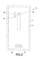
Fig. 2 is a rear view of the apparatus shown inFig. 1 ; -
Fig. 3 is a diagram illustrating some of the components of the apparatus shown inFigs. 1-2 ; -
Fig. 4 is a partial exploded perspective view of some of the components of the apparatus shown inFig. 1 ; -
Fig. 5 is a schematic cross section view of the speaker shown inFig. 4 ; -
Fig. 6 is a schematic view illustrating connection of the speaker to a printed wiring board; -
Fig. 7 is a perspective view of the speaker shown inFig. 4 ; -
Fig. 8 is a bottom plan view of the speaker shown inFig. 7 ; and -
Fig. 9 is a diagram illustrating components of an example embodiment. - Referring to
Fig. 1 , there is shown a front view of anapparatus 10 incorporating features of an example embodiment. Although the features will be described with reference to the example embodiments shown in the drawings, it should be understood that features can be embodied in many alternate forms of embodiments. In addition, any suitable size, shape or type of elements or materials could be used. - The
apparatus 10 may be a hand-held portable apparatus, such as a communications device which includes a telephone application for example. In the example shown theapparatus 10 is a smartphone which includes a camera and a camera application. Theapparatus 10 may additionally or alternatively comprise an Internet browser application, a video recorder application, a music player and recorder application, an email application, a navigation application, a gaming application, and/or any other suitable electronic device application. In an alternate example embodiment the apparatus might not be a smartphone. For example, the apparatus might be a video recorder or a hand-held gaming device for example. - Referring also to
Figs. 2-3 , theapparatus 10, in this example embodiment, comprises ahousing 12, atouchscreen 14, areceiver 16, atransmitter 18, acontroller 20, arechargeable battery 26 and acamera 30. However, all of these features are not necessary to implement the features described below. The receiver and the transmitter may be provided in the form of a transceiver for example. Thecontroller 20 may include at least oneprocessor 22, at least onememory 24, and software. The electronic circuitry inside thehousing 12 may comprise at least one printed wiring board (PWB) having components such as thecontroller 20 thereon. Thereceiver 16 andtransmitter 18 form a primary communications system to allow theapparatus 10 to communicate with a wireless telephone system, such as a mobile telephone base station for example. - In this example, the
apparatus 10 includes thecamera 30 which is located at therear side 13 of the apparatus, afront camera 32, anLED 34, and aflash system 36. TheLED 34 and theflash system 36 are also visible at the rear side of the apparatus, and are provided for thecamera 30. Thecameras LED 34 and theflash system 36 are connected to thecontroller 20 such that thecontroller 20 may control their operation. In an alternate example embodiment the rear side may comprise more than one camera, and/or the front side could comprise more than one camera. Theapparatus 10 includes a sound transducer provided as anair microphone 38. In an alternate example the apparatus may comprise more than one air microphone. - The
apparatus 10 also includes a speaker orearpiece 28 which comprises a sound transducer. Referring also toFig. 4 , theapparatus 10 includes aspeaker 40. Thehousing 12 comprises at least onesound hole 33 for sound to travel from theearpiece 28, at least onesound hole 39 for sound to travel to the microphone, andsound holes 42 for sound to travel from thespeaker 40. The description which follows will be in regard to the area at thespeaker 40. However, the features described are equally applicable to other coil/magnet assemblies. Features of the invention could be used at theearpiece 28 for example. In the example shown thediaphragm 48 of thespeaker 40 has its outer perimeter connected to ahousing 50 which can be mounted to a backside of aframe piece 52. - Referring also to
Figs. 5-6 , thespeaker 40 includes amagnet system 44, acoil 46, and thediaphragm 48 connected to thecoil 44. Themagnet system 44 comprises at least onepermanent magnet 54 andpole pieces U.S. patent publication No. 2013/0278364 A1 which is hereby incorporated by reference in its entirety. - In the example shown in
Figs. 4-6 thecoil 46 is energized to move thecoil 46 and thediaphragm 48 relative to themagnet system 44 as indicated byarrow 58. In the example shown thediaphragm 48 comprises anmembrane 60. Themembrane 60 comprises an electrically conductive material. Themetal membrane 60 may comprises aluminum for example. As themembrane 60 is moved as indicated byarrow 58, sound is produced from thespeaker 40. Themembrane 60 includes at least oneelectrical connector 62. The electrical connector orcontact 62 may be a ground pin for example. Theelectrical connector 62 in this example comprises twoelectrical connectors electrical connector 62a may be provided. As another example embodiment, only theelectrical connector 62b may be provided. In one type of example embodiment thecontacts 62 are integrally formed with themetal membrane 60. However, in an alternate example the connector/contact 62 for themetal membrane 60 may not be integrally formed with the metal membrane. The electrical connector(s) could be a separate member from the metal membrane. Each of theelectrical connectors electrical connection area 64 to connect themetal membrane 60 to ground. As used herein, an indication that a connector(s) is configured to connect the membrane to ground is intended to include where a galvanic connection is provided of the connector to the ground or where a small gap is provided between the connector and the ground (as further described below). - The first
electrical connector 62a is a resiliently deflectable cantilevered arm having itselectrical connection area 64 at the distal end of the arm. Theelectrical connection area 64 of the firstelectrical connector 62a is located against the top surface of thepole piece 56a. Thepole piece 56b is mounted on the printed wiring board (PWB) 66 and is electrically connected to aground layer 68 of thePWB 66. Thus, themetal membrane 60 is electrically connected to theground layer 68 by the twopole pieces conductive magnet 54. - The second
electrical connector 62b is a resiliently deflectable cantilevered arm having itselectrical connection area 64 at the distal end of the arm. Theelectrical connection area 64 of the secondelectrical connector 62b is located against the top surface of thePWB 66; against acontact pad 70 of theground layer 68. Thus, themetal membrane 60 is electrically connected to theground layer 68 by theconnector 62b. One or both of theconnectors 62 may comprise, for example, a spring terminal, a leaf terminal, or a non-resilient terminal, such as connection pads suitably designed as part of the transducer chassis. - Features as described herein may be used with speakers, earpieces, transducer integration to mechanics, acoustics, and ESD protection. Features may apply to any type of speaker or earpiece in mobile devices, such as mobile phones, tablets, navigation devices, PDAs and laptops.
- A spark from an electrostatic discharge (ESD) can easily upset or break a modern integrated handsfree (IHF)
speaker amplifier 72 when the ESD conducts into the sound outlet and to the speaker. Modern speaker amplifiers are very vulnerable to ESD due to limitations in silicon area, cost, and increased digital signal processing (DSP) on chip (audio DSP algorithms, speaker protection, etc). - One type of fix for the problem may comprise adding passive components (ferrites, varistors) in speaker lines to protect the
amplifier 72. However, these passive components are costly, they require PWB footprint, cause extra logistics effort, slow down production and add complexity. Also, the audio performance will be lower than with a simple circuit with less losses and resistance. - Another way to protect the speaker from an ESD spark is to add a metal plate in front of the speaker that presents low impedance to ground for the ESD spark, so that the ESD spark can be guided to ground. This can be achieved by either directly grounding the metal plate to the system ground or very narrow spark gap to the ground. However, adding a separate metal plate is rarely possible in product design due to added Z height and design complexity. The extra plate needs to be acoustically sealed to the component by adhesive or a poron layer which add more Z height, and adds design and assembly complexity. Such kind of structure is also challenging for design and assembly task and, in many products, not even possible. Adding a separate metal plate and acoustically sealing it with adhesive/poron layer might be provided without grounding the plate, but the plate would be floating (not grounded), and it is not possible to get low impedance to ground so that an ESD spark can be easily guided to ground. A floating plate in that way has a high ESD risk. Grounding the plate requires extra design effort from product mechanics and is not possible in many designs. Some conventional mobile phones use a speaker with a metal (e.g., aluminum) membrane to get better bass effect. However, the metal membrane is not connected to ground and, therefore, does not provide ESD shielding as noted in the floating plate construction described above.
- Features as described herein may be used to solve the ESD shielding problem with use of a metal speaker membrane as an ESD shield by connecting the metal membrane to ground. Thus, the ESD shield does not need to be provide as a separate part. Instead, a single member (such as membrane 60) can be used to accomplish two functions, namely, speaker diaphragm and ESD shielding. The result is a re-designed speaker with an integrated ESD protection. Grounding the front metal plate to the PWB may be provided by designing a third contact leg from the speaker to the PWB (where the coil has the two other contact legs/leads 74, 75 shown in
Figs. 7-8 ). By merely connecting themetal plate 60 to ground, this will take care of the ESD problem. Features as described herein may provide a ready solution (fully integrated speaker component) that includes the grounded metal plate for ESD protection. - Using the metal membrane as both a speaker diaphragm and as an ESD shield reduces the total solution Z thickness because no separate adhesive/poron layer is needed between the speaker component and shield plate. In logistics and mechanical integration, it is more convenient to have the whole package integrated as one unit compared to building the solution from pieces and designing separate wiring for grounding the metal plate onto the PWB.
- Features as described herein may be used to provide a novel speaker module design solution with effective integrated ESD protection that can reuse the existing structure (e.g., metal membrane) as much as possible. ESD is firstly attracted by the metal membrane and then guided to
system ground 68 in the PWB through the low impedance path between themembrane 60 and system ground. The low impedance path can be achieved by either the direct Galvanic connection or a small air gap (e.g., <0.5mm) between the membrane and the GND. Thus, the connector(s) may be configured to indirectly connect the membrane to ground through a small air gap; not necessarily a direct connection to the ground. In one example simulation, without features as described herein, thedriver 72 can be damaged by a 12kV air discharge. However, with features as described herein spark routing protocol (SPR) at 15kV can be passed. - With features as described herein, effective ESD protection may be provided. It can effectively trap the ESD sparks from all the directions to the speaker and guide them to ground, providing effective protection for both positive and negative terminals of the
driver 72. There is no penalty in z-direction thickness as there is no need for an additional metal layer below or above the module. There is minimal cost increase as there is no need for an additional metal film. Regarding the impact on acoustic performance, this can be minimal. The grounding contact(s) 62 on themembrane 60 may be located at where themembrane 60 is fixed to thehousing 50, therefore, it will not impact the vibration of the diaphragm. ESD protection also works without direct galvanic contact, if the air gap between the membrane and the grounding is small enough (such as less than 0.5mm for example). - The
metal membrane 60 may be connected/wired to a separate ground pin internally (now shown). However, a dedicated ground pin(s) is not required because the membrane can connect to the pole piece/magnet (below which is electrically conductive), and/or can be connected to ground by an external spring/leaf/conducting gasket on the PWB (or flexible printed circuit FPC). - There are some other types of speakers without metal membrane. In these cases, the speaker may have a floating metal cover over the top edge of the speaker, but which is not connected to ground. Similar as the embodiment of grounding of the metal membrane, grounding of the metal cover inside the speaker module can also distinctively improve the ESD performance.
- Electrically connecting the metal membrane to the ground on PWB/FPC is convenient with the
leg contact 62. Modern IHF amplifiers' ESD vulnerability problem is solved by a grounded plate as the membrane of the speaker. Features include ease of design and assembly, easier logistics and smaller product design, manufacturing and care cost. - Referring also to
Figs. 7 and 8 , bottom views an example embodiment of thespeaker 40 is shown. 74, 75 are electrical leads for thecoil 46. Two of theelectrical connectors 62b are provided. Theconnectors 62b each have a general cantilevered shape which is surface mounted to thePWB 66. - The
connectors 62b are electrically connected to the diaphragm at the perimeter edge of the diaphragm; where the diaphragm is connected to thehousing 50. Therefore, theconnectors 62b will not impact the vibration of the diaphragm. In one type of alternate example embodiment the diaphragm may comprise an assembly of components such as a resilient polymer membrane with a sprayed-on or attached electrically conductive member with a connector or contact to connect the metal member to ground. For the example embodiment shown inFigs. 7-8 , thespeaker 40 has both the electrical leads 74, 75 to drive thecoil 46, and at least one additional terminal (in thisexample terminals 62b) which all connect to a printedwiring board 66 when thespeaker 40 is mounted to thePWB 66. Thus, thespeaker 40 has at least one additional contact terminal for the speaker module in addition to theelectrical terminals - Referring also to
Fig. 9 , an example embodiment may comprise thediaphragm 48, adrive 78 and the electrical connector/contact 62. Thedrive 78 may comprise thecoil 46 and permanent magnet(s) 44 described above. In an alternate example embodiment the drive may comprise, for example, a piezoelectric drive or an electrostatic drive, such as for a piezoelectric speaker or a electrostatic speaker. Any suitable drive could be used. - An example embodiment may be provided in an apparatus comprising a magnet system; at least one pole piece connected to the magnet system; a coil; and a diaphragm connected to the coil, where the diaphragm comprises a metal membrane having a connector for electrically connecting the metal membrane to ground.
- The apparatus may further comprise
electrical insulation 76 between the metal membrane and the coil. The connector may comprise a resilient electrical contact arm which is configured to resiliently deflect. The resilient electrical contact arm may comprise a surface mount contact area adapted to make a surface contact with another member. The resilient electrical contact arm may make the surface contact with a contact pad on a printed wiring board. The resilient electrical contact arm may make the surface contact with a first one of the at least one pole piece. The connector may be electrically connected in series to a first one of the at least one pole piece, at least one magnet of the magnet system, and a second one of the at least one pole piece. The apparatus may comprise means for electrostatic discharge shielding comprising the metal membrane of the diaphragm. The apparatus may further comprise a printed wiring board having a ground, where the metal membrane is connected to the ground by the connector; an electrical display connected to the printed wiring board; a receiver connected to the printed wiring board; a transmitter connected to the printed wiring board; a processor connected to the printed wiring board; a memory connected to the printed wiring board; and a battery connected to the printed wiring board. - An example method may comprise providing a speaker diaphragm comprising a metal membrane, where the metal membrane comprises an electrical connection area adapted to connect the metal membrane to ground; and connecting the diaphragm to a coil.
- The method may further comprise electrically insulating the metal membrane from the coil. The metal membrane may comprise a resiliently deflectable arm having the electrical connection area thereon. A majority of the metal membrane may be stationarily connected to the coil to move with the coil. The method may further comprise electrically connecting the electrical connection area of the metal membrane on an electrical contact pad of a printed wiring board. The method may further comprise electrically connecting the electrical connection area of the metal membrane on to a pole piece connected to a magnet.
- An example method may comprise providing a speaker comprising a diaphragm which includes a metal membrane, where the metal membrane comprises an electrical connection section; and connecting the speaker to a printed wiring board, where, when the speaker is connected to the printed wiring board, the metal membrane is electrically connected through the electrical connection section to the printed wiring board.
- The electrical connection section of the metal membrane may be provided as a resiliently deflectable arm having the electrical connection area thereon. The electrical connection area may contact a contact pad on the printed wiring board. The electrical connection area may contact a pole piece of the speaker, where the metal membrane is electrically connected to the printed wiring board through the pole piece. Connecting the speaker to the printed wiring board may comprise resiliently deflecting the electrical connection section of the metal membrane.
- It should be understood that the foregoing description is only illustrative. Various alternatives and modifications can be devised by those skilled in the art. For example, features recited in the various dependent claims could be combined with each other in any suitable combination(s). In addition, features from different embodiments described above could be selectively combined into a new embodiment. Accordingly, the description is intended to embrace all such alternatives, modifications and variances which fall within the scope of the appended claims.
Claims (15)
- An apparatus comprising:a diaphragm comprises a membrane comprising electrically conductive material;a drive configured to move the diaphragm when an audio signal is received; anda connector configured to connect the membrane to a ground in use, where the apparatus comprises an audio transducer formed by the diaphragm and the drive.
- The apparatus as in claim 1, where the drive comprises a magnet system, at least one pole piece connected to the magnet system, and a coil, where electrical insulation is provided between the membrane and the coil.
- The apparatus as in any of claims 1 and 2, where the connector comprises a resilient electrical contact which is configured to resiliently deflect.
- The apparatus as in claim 3, where the resilient electrical contact comprises a surface mount contact area adapted to make a surface contact with another member.
- The apparatus as in any of claims 3 and 4, where the resilient electrical contact makes the surface contact with a contact pad on a printed wiring board.
- The apparatus as in any of claims 3 and 4, where the resilient electrical contact makes the surface contact with a first one pole piece of the drive.
- The apparatus as in any preceding claim, where the connector is electrically connected in series to a first pole piece of the drive, at least one magnet of a magnet system of the drive, and a second pole piece of the drive.
- The apparatus as in any preceding claim, where the apparatus comprises means for electrostatic discharge shielding comprising the membrane of the diaphragm.
- The apparatus as in any preceding claim, further comprising:a printed wiring board having a ground, where the membrane is connected to the ground by the connector;an electrical display connected to the printed wiring board;a receiver connected to the printed wiring board;a transmitter connected to the printed wiring board;a processor connected to the printed wiring board;a memory connected to the printed wiring board; anda battery connected to the printed wiring board.
- The apparatus as in any preceding claim, where the apparatus is a speaker module comprising at least three electrical leads, where the at least three electrical leads comprise:at least two leads with the drive, andat least one separate lead with the membrane, where the at least one separate lead is provided by the connector.
- The apparatus as in any preceding claim, where the connector is configured to provide a gap between the connector and a ground contact area on a printed wiring board when the apparatus is connected to the printed wiring board, where the connector is not galvanically connected to the printed wiring board.
- A method comprising:providing a speaker diaphragm, where the speaker diaphragm comprises a membrane, where the membrane comprises electrically conductive material, where the membrane comprises a connector configured to connect the membrane to a ground; andconnecting the diaphragm to a drive, where the drive is configured to move the diaphragm.
- The method as in claim 12, further comprising:providing the membrane with an electrical connection section to connect the membrane to the ground; and connecting the membrane to a printed wiring board, where, when the membrane is connected to the printed wiring board, the membrane is electrically connected through the electrical connection section to the printed wiring board.
- The method as in claim 13, where the electrical connection section of the membrane is provided as a resiliently deflectable contact having the electrical connection area thereon, where the electrical connection area contacts a contact pad on the printed wiring board.
- The method as in claim 13, where the electrical connection section of the membrane is provided as a resiliently deflectable contact having the electrical connection area thereon, where the electrical connection area contacts a pole piece of a speaker comprising the membrane, where the membrane is electrically connected to the printed wiring board through the pole piece.
Applications Claiming Priority (1)
| Application Number | Priority Date | Filing Date | Title |
|---|---|---|---|
| US14/087,078 US9301053B2 (en) | 2013-11-22 | 2013-11-22 | Audio transducer with electrostatic discharge protection |
Publications (2)
| Publication Number | Publication Date |
|---|---|
| EP2876896A1 true EP2876896A1 (en) | 2015-05-27 |
| EP2876896B1 EP2876896B1 (en) | 2017-12-27 |
Family
ID=51846557
Family Applications (1)
| Application Number | Title | Priority Date | Filing Date |
|---|---|---|---|
| EP14191973.8A Active EP2876896B1 (en) | 2013-11-22 | 2014-11-06 | Audio transducer with electrostatic discharge protection |
Country Status (2)
| Country | Link |
|---|---|
| US (1) | US9301053B2 (en) |
| EP (1) | EP2876896B1 (en) |
Cited By (2)
| Publication number | Priority date | Publication date | Assignee | Title |
|---|---|---|---|---|
| EP2934023A1 (en) * | 2014-04-17 | 2015-10-21 | Nokia Technologies Oy | Audio transducer with electrostatic discharge protection |
| US9301053B2 (en) | 2013-11-22 | 2016-03-29 | Nokia Corporation | Audio transducer with electrostatic discharge protection |
Families Citing this family (4)
| Publication number | Priority date | Publication date | Assignee | Title |
|---|---|---|---|---|
| KR101410393B1 (en) * | 2012-09-25 | 2014-06-23 | 주식회사 에스제이앤에스 | Speaker frame and speaker having the same |
| JP5707454B2 (en) * | 2013-07-22 | 2015-04-30 | 京セラ株式会社 | Electronics |
| CN109672964B (en) * | 2018-11-16 | 2020-05-29 | 歌尔股份有限公司 | Loudspeaker module and electronic equipment |
| CN213586253U (en) * | 2019-12-30 | 2021-06-29 | 美商楼氏电子有限公司 | Balanced armature receiver |
Citations (6)
| Publication number | Priority date | Publication date | Assignee | Title |
|---|---|---|---|---|
| US2857461A (en) * | 1954-09-03 | 1958-10-21 | Thompson Prod Inc | Speaker diaphragm controlled capacitor for negative feedback control |
| US3061675A (en) * | 1958-09-09 | 1962-10-30 | Texas Instruments Inc | Loud speaker improvement |
| DE3218323A1 (en) * | 1982-05-14 | 1983-11-17 | Bosch-Siemens Hausgeräte GmbH, 7000 Stuttgart | Electroacoustical transducer with mounting and connecting elements |
| US5878149A (en) * | 1993-10-08 | 1999-03-02 | Pioneer Electronic Corporation | Loudspeaker having a yoke, magnet, cylindrical throat, and spacer plate configuration |
| US20050207610A1 (en) * | 2004-03-18 | 2005-09-22 | Hiroo Kajiwara | Multifunction speaker |
| US20130278364A1 (en) | 2012-04-18 | 2013-10-24 | Nokia Corporation | Sound Generating Apparatus |
Family Cites Families (11)
| Publication number | Priority date | Publication date | Assignee | Title |
|---|---|---|---|---|
| US5406038A (en) | 1994-01-31 | 1995-04-11 | Motorola, Inc. | Shielded speaker |
| US7012796B2 (en) | 2003-05-21 | 2006-03-14 | Arima Computer Corporation | Electrostatic discharge protection apparatus |
| TWI269599B (en) | 2005-02-15 | 2006-12-21 | Mitac Int Corp | Earphone speaker with electrostatic discharge protection |
| US20060250731A1 (en) | 2005-05-03 | 2006-11-09 | Parkhurst Ray M | System and method for electrostatic discharge protection in an electronic circuit |
| EP1990834B1 (en) | 2007-05-10 | 2012-08-15 | Texas Instruments France | Local integration of non-linear sheet in integrated circuit packages for ESD/EOS protection |
| TWI336597B (en) | 2007-08-07 | 2011-01-21 | Cotron Corp | Earphone speaker with esd protection |
| US7869206B2 (en) * | 2008-09-05 | 2011-01-11 | Apple Inc. | Handheld computing device |
| TW201101450A (en) | 2009-06-22 | 2011-01-01 | Askey Computer Corp | Electrostatic discharge (ESD) protection method and structure for electronic product |
| CN101958534B (en) | 2009-07-15 | 2015-04-15 | 中山市云创知识产权服务有限公司 | Electrostatic discharge module and mobile communication device with electrostatic discharge module |
| US9210497B2 (en) | 2012-09-06 | 2015-12-08 | Shure Acquisition Holdings, Inc. | Electrostatic earphone |
| US9301053B2 (en) | 2013-11-22 | 2016-03-29 | Nokia Corporation | Audio transducer with electrostatic discharge protection |
-
2013
- 2013-11-22 US US14/087,078 patent/US9301053B2/en active Active
-
2014
- 2014-11-06 EP EP14191973.8A patent/EP2876896B1/en active Active
Patent Citations (6)
| Publication number | Priority date | Publication date | Assignee | Title |
|---|---|---|---|---|
| US2857461A (en) * | 1954-09-03 | 1958-10-21 | Thompson Prod Inc | Speaker diaphragm controlled capacitor for negative feedback control |
| US3061675A (en) * | 1958-09-09 | 1962-10-30 | Texas Instruments Inc | Loud speaker improvement |
| DE3218323A1 (en) * | 1982-05-14 | 1983-11-17 | Bosch-Siemens Hausgeräte GmbH, 7000 Stuttgart | Electroacoustical transducer with mounting and connecting elements |
| US5878149A (en) * | 1993-10-08 | 1999-03-02 | Pioneer Electronic Corporation | Loudspeaker having a yoke, magnet, cylindrical throat, and spacer plate configuration |
| US20050207610A1 (en) * | 2004-03-18 | 2005-09-22 | Hiroo Kajiwara | Multifunction speaker |
| US20130278364A1 (en) | 2012-04-18 | 2013-10-24 | Nokia Corporation | Sound Generating Apparatus |
Cited By (3)
| Publication number | Priority date | Publication date | Assignee | Title |
|---|---|---|---|---|
| US9301053B2 (en) | 2013-11-22 | 2016-03-29 | Nokia Corporation | Audio transducer with electrostatic discharge protection |
| EP2934023A1 (en) * | 2014-04-17 | 2015-10-21 | Nokia Technologies Oy | Audio transducer with electrostatic discharge protection |
| US10448165B2 (en) | 2014-04-17 | 2019-10-15 | Nokia Technologies Oy | Audio transducer with electrostatic discharge protection |
Also Published As
| Publication number | Publication date |
|---|---|
| EP2876896B1 (en) | 2017-12-27 |
| US20150146914A1 (en) | 2015-05-28 |
| US9301053B2 (en) | 2016-03-29 |
Similar Documents
| Publication | Publication Date | Title |
|---|---|---|
| EP2876896B1 (en) | Audio transducer with electrostatic discharge protection | |
| US8670579B2 (en) | MEMS microphone | |
| US8428285B2 (en) | Microphone screen with common mode interference reduction | |
| US9544678B2 (en) | Printed circuit board with an acoustic channel for a microphone | |
| US8041064B2 (en) | Card type MEMS microphone | |
| EP2934023B1 (en) | Audio transducer with electrostatic discharge protection | |
| US9788093B2 (en) | Audio transducer electrical connectivity | |
| US9369787B2 (en) | Shielded audio apparatus | |
| US10057670B2 (en) | Apparatus and method for providing an apparatus comprising an audio transducer | |
| US20130148837A1 (en) | Multi-functional microphone assembly and method of manufacturing the same | |
| CN104871561A (en) | Apparatus to prevent excess movement of mems components | |
| CN102611954A (en) | Microphone dustproof structure and assembling method thereof | |
| US10334341B2 (en) | Apparatus and method for providing an apparatus comprising a covering portion for an electronic device | |
| CN106254592A (en) | A kind of mobile terminal | |
| CN101374362B (en) | Headphone speaker with anti-static circuit board | |
| JP2011029841A (en) | Portable communication apparatus | |
| CN102143667A (en) | Electronic device | |
| CN212115610U (en) | Earphone set | |
| CN202178855U (en) | Microphone | |
| CN217985644U (en) | Electronic device | |
| TWI455601B (en) | Electro-acoustic transducer with reaction capability |
Legal Events
| Date | Code | Title | Description |
|---|---|---|---|
| PUAI | Public reference made under article 153(3) epc to a published international application that has entered the european phase |
Free format text: ORIGINAL CODE: 0009012 |
|
| 17P | Request for examination filed |
Effective date: 20141106 |
|
| AK | Designated contracting states |
Kind code of ref document: A1 Designated state(s): AL AT BE BG CH CY CZ DE DK EE ES FI FR GB GR HR HU IE IS IT LI LT LU LV MC MK MT NL NO PL PT RO RS SE SI SK SM TR |
|
| AX | Request for extension of the european patent |
Extension state: BA ME |
|
| RAP1 | Party data changed (applicant data changed or rights of an application transferred) |
Owner name: NOKIA TECHNOLOGIES OY |
|
| R17P | Request for examination filed (corrected) |
Effective date: 20151124 |
|
| RBV | Designated contracting states (corrected) |
Designated state(s): AL AT BE BG CH CY CZ DE DK EE ES FI FR GB GR HR HU IE IS IT LI LT LU LV MC MK MT NL NO PL PT RO RS SE SI SK SM TR |
|
| 17Q | First examination report despatched |
Effective date: 20160204 |
|
| GRAP | Despatch of communication of intention to grant a patent |
Free format text: ORIGINAL CODE: EPIDOSNIGR1 |
|
| INTG | Intention to grant announced |
Effective date: 20170719 |
|
| GRAA | (expected) grant |
Free format text: ORIGINAL CODE: 0009210 |
|
| GRAS | Grant fee paid |
Free format text: ORIGINAL CODE: EPIDOSNIGR3 |
|
| AK | Designated contracting states |
Kind code of ref document: B1 Designated state(s): AL AT BE BG CH CY CZ DE DK EE ES FI FR GB GR HR HU IE IS IT LI LT LU LV MC MK MT NL NO PL PT RO RS SE SI SK SM TR |
|
| REG | Reference to a national code |
Ref country code: GB Ref legal event code: FG4D |
|
| REG | Reference to a national code |
Ref country code: CH Ref legal event code: EP |
|
| REG | Reference to a national code |
Ref country code: AT Ref legal event code: REF Ref document number: 959271 Country of ref document: AT Kind code of ref document: T Effective date: 20180115 |
|
| REG | Reference to a national code |
Ref country code: IE Ref legal event code: FG4D |
|
| REG | Reference to a national code |
Ref country code: DE Ref legal event code: R096 Ref document number: 602014019030 Country of ref document: DE |
|
| REG | Reference to a national code |
Ref country code: NL Ref legal event code: FP |
|
| PG25 | Lapsed in a contracting state [announced via postgrant information from national office to epo] |
Ref country code: LT Free format text: LAPSE BECAUSE OF FAILURE TO SUBMIT A TRANSLATION OF THE DESCRIPTION OR TO PAY THE FEE WITHIN THE PRESCRIBED TIME-LIMIT Effective date: 20171227 Ref country code: NO Free format text: LAPSE BECAUSE OF FAILURE TO SUBMIT A TRANSLATION OF THE DESCRIPTION OR TO PAY THE FEE WITHIN THE PRESCRIBED TIME-LIMIT Effective date: 20180327 Ref country code: FI Free format text: LAPSE BECAUSE OF FAILURE TO SUBMIT A TRANSLATION OF THE DESCRIPTION OR TO PAY THE FEE WITHIN THE PRESCRIBED TIME-LIMIT Effective date: 20171227 |
|
| REG | Reference to a national code |
Ref country code: LT Ref legal event code: MG4D |
|
| REG | Reference to a national code |
Ref country code: AT Ref legal event code: MK05 Ref document number: 959271 Country of ref document: AT Kind code of ref document: T Effective date: 20171227 |
|
| PG25 | Lapsed in a contracting state [announced via postgrant information from national office to epo] |
Ref country code: HR Free format text: LAPSE BECAUSE OF FAILURE TO SUBMIT A TRANSLATION OF THE DESCRIPTION OR TO PAY THE FEE WITHIN THE PRESCRIBED TIME-LIMIT Effective date: 20171227 Ref country code: GR Free format text: LAPSE BECAUSE OF FAILURE TO SUBMIT A TRANSLATION OF THE DESCRIPTION OR TO PAY THE FEE WITHIN THE PRESCRIBED TIME-LIMIT Effective date: 20180328 Ref country code: LV Free format text: LAPSE BECAUSE OF FAILURE TO SUBMIT A TRANSLATION OF THE DESCRIPTION OR TO PAY THE FEE WITHIN THE PRESCRIBED TIME-LIMIT Effective date: 20171227 Ref country code: BG Free format text: LAPSE BECAUSE OF FAILURE TO SUBMIT A TRANSLATION OF THE DESCRIPTION OR TO PAY THE FEE WITHIN THE PRESCRIBED TIME-LIMIT Effective date: 20180327 Ref country code: RS Free format text: LAPSE BECAUSE OF FAILURE TO SUBMIT A TRANSLATION OF THE DESCRIPTION OR TO PAY THE FEE WITHIN THE PRESCRIBED TIME-LIMIT Effective date: 20171227 |
|
| PG25 | Lapsed in a contracting state [announced via postgrant information from national office to epo] |
Ref country code: EE Free format text: LAPSE BECAUSE OF FAILURE TO SUBMIT A TRANSLATION OF THE DESCRIPTION OR TO PAY THE FEE WITHIN THE PRESCRIBED TIME-LIMIT Effective date: 20171227 Ref country code: CY Free format text: LAPSE BECAUSE OF FAILURE TO SUBMIT A TRANSLATION OF THE DESCRIPTION OR TO PAY THE FEE WITHIN THE PRESCRIBED TIME-LIMIT Effective date: 20171227 Ref country code: CZ Free format text: LAPSE BECAUSE OF FAILURE TO SUBMIT A TRANSLATION OF THE DESCRIPTION OR TO PAY THE FEE WITHIN THE PRESCRIBED TIME-LIMIT Effective date: 20171227 Ref country code: SK Free format text: LAPSE BECAUSE OF FAILURE TO SUBMIT A TRANSLATION OF THE DESCRIPTION OR TO PAY THE FEE WITHIN THE PRESCRIBED TIME-LIMIT Effective date: 20171227 Ref country code: ES Free format text: LAPSE BECAUSE OF FAILURE TO SUBMIT A TRANSLATION OF THE DESCRIPTION OR TO PAY THE FEE WITHIN THE PRESCRIBED TIME-LIMIT Effective date: 20171227 |
|
| PG25 | Lapsed in a contracting state [announced via postgrant information from national office to epo] |
Ref country code: AT Free format text: LAPSE BECAUSE OF FAILURE TO SUBMIT A TRANSLATION OF THE DESCRIPTION OR TO PAY THE FEE WITHIN THE PRESCRIBED TIME-LIMIT Effective date: 20171227 Ref country code: IT Free format text: LAPSE BECAUSE OF FAILURE TO SUBMIT A TRANSLATION OF THE DESCRIPTION OR TO PAY THE FEE WITHIN THE PRESCRIBED TIME-LIMIT Effective date: 20171227 Ref country code: SM Free format text: LAPSE BECAUSE OF FAILURE TO SUBMIT A TRANSLATION OF THE DESCRIPTION OR TO PAY THE FEE WITHIN THE PRESCRIBED TIME-LIMIT Effective date: 20171227 Ref country code: RO Free format text: LAPSE BECAUSE OF FAILURE TO SUBMIT A TRANSLATION OF THE DESCRIPTION OR TO PAY THE FEE WITHIN THE PRESCRIBED TIME-LIMIT Effective date: 20171227 Ref country code: IS Free format text: LAPSE BECAUSE OF FAILURE TO SUBMIT A TRANSLATION OF THE DESCRIPTION OR TO PAY THE FEE WITHIN THE PRESCRIBED TIME-LIMIT Effective date: 20180427 Ref country code: PL Free format text: LAPSE BECAUSE OF FAILURE TO SUBMIT A TRANSLATION OF THE DESCRIPTION OR TO PAY THE FEE WITHIN THE PRESCRIBED TIME-LIMIT Effective date: 20171227 |
|
| REG | Reference to a national code |
Ref country code: DE Ref legal event code: R097 Ref document number: 602014019030 Country of ref document: DE |
|
| PLBE | No opposition filed within time limit |
Free format text: ORIGINAL CODE: 0009261 |
|
| STAA | Information on the status of an ep patent application or granted ep patent |
Free format text: STATUS: NO OPPOSITION FILED WITHIN TIME LIMIT |
|
| PG25 | Lapsed in a contracting state [announced via postgrant information from national office to epo] |
Ref country code: DK Free format text: LAPSE BECAUSE OF FAILURE TO SUBMIT A TRANSLATION OF THE DESCRIPTION OR TO PAY THE FEE WITHIN THE PRESCRIBED TIME-LIMIT Effective date: 20171227 |
|
| 26N | No opposition filed |
Effective date: 20180928 |
|
| PG25 | Lapsed in a contracting state [announced via postgrant information from national office to epo] |
Ref country code: SI Free format text: LAPSE BECAUSE OF FAILURE TO SUBMIT A TRANSLATION OF THE DESCRIPTION OR TO PAY THE FEE WITHIN THE PRESCRIBED TIME-LIMIT Effective date: 20171227 |
|
| REG | Reference to a national code |
Ref country code: CH Ref legal event code: PL |
|
| PG25 | Lapsed in a contracting state [announced via postgrant information from national office to epo] |
Ref country code: MC Free format text: LAPSE BECAUSE OF FAILURE TO SUBMIT A TRANSLATION OF THE DESCRIPTION OR TO PAY THE FEE WITHIN THE PRESCRIBED TIME-LIMIT Effective date: 20171227 Ref country code: LU Free format text: LAPSE BECAUSE OF NON-PAYMENT OF DUE FEES Effective date: 20181106 |
|
| REG | Reference to a national code |
Ref country code: BE Ref legal event code: MM Effective date: 20181130 |
|
| REG | Reference to a national code |
Ref country code: IE Ref legal event code: MM4A |
|
| PG25 | Lapsed in a contracting state [announced via postgrant information from national office to epo] |
Ref country code: LI Free format text: LAPSE BECAUSE OF NON-PAYMENT OF DUE FEES Effective date: 20181130 Ref country code: CH Free format text: LAPSE BECAUSE OF NON-PAYMENT OF DUE FEES Effective date: 20181130 |
|
| PG25 | Lapsed in a contracting state [announced via postgrant information from national office to epo] |
Ref country code: IE Free format text: LAPSE BECAUSE OF NON-PAYMENT OF DUE FEES Effective date: 20181106 Ref country code: FR Free format text: LAPSE BECAUSE OF NON-PAYMENT OF DUE FEES Effective date: 20181130 |
|
| PG25 | Lapsed in a contracting state [announced via postgrant information from national office to epo] |
Ref country code: BE Free format text: LAPSE BECAUSE OF NON-PAYMENT OF DUE FEES Effective date: 20181130 |
|
| PG25 | Lapsed in a contracting state [announced via postgrant information from national office to epo] |
Ref country code: MT Free format text: LAPSE BECAUSE OF NON-PAYMENT OF DUE FEES Effective date: 20181106 |
|
| PG25 | Lapsed in a contracting state [announced via postgrant information from national office to epo] |
Ref country code: TR Free format text: LAPSE BECAUSE OF FAILURE TO SUBMIT A TRANSLATION OF THE DESCRIPTION OR TO PAY THE FEE WITHIN THE PRESCRIBED TIME-LIMIT Effective date: 20171227 |
|
| PG25 | Lapsed in a contracting state [announced via postgrant information from national office to epo] |
Ref country code: PT Free format text: LAPSE BECAUSE OF FAILURE TO SUBMIT A TRANSLATION OF THE DESCRIPTION OR TO PAY THE FEE WITHIN THE PRESCRIBED TIME-LIMIT Effective date: 20171227 |
|
| PG25 | Lapsed in a contracting state [announced via postgrant information from national office to epo] |
Ref country code: HU Free format text: LAPSE BECAUSE OF FAILURE TO SUBMIT A TRANSLATION OF THE DESCRIPTION OR TO PAY THE FEE WITHIN THE PRESCRIBED TIME-LIMIT; INVALID AB INITIO Effective date: 20141106 Ref country code: MK Free format text: LAPSE BECAUSE OF NON-PAYMENT OF DUE FEES Effective date: 20171227 Ref country code: SE Free format text: LAPSE BECAUSE OF FAILURE TO SUBMIT A TRANSLATION OF THE DESCRIPTION OR TO PAY THE FEE WITHIN THE PRESCRIBED TIME-LIMIT Effective date: 20171227 |
|
| PG25 | Lapsed in a contracting state [announced via postgrant information from national office to epo] |
Ref country code: AL Free format text: LAPSE BECAUSE OF FAILURE TO SUBMIT A TRANSLATION OF THE DESCRIPTION OR TO PAY THE FEE WITHIN THE PRESCRIBED TIME-LIMIT Effective date: 20171227 |
|
| P01 | Opt-out of the competence of the unified patent court (upc) registered |
Effective date: 20230527 |
|
| PGFP | Annual fee paid to national office [announced via postgrant information from national office to epo] |
Ref country code: NL Payment date: 20241004 Year of fee payment: 11 |
|
| PGFP | Annual fee paid to national office [announced via postgrant information from national office to epo] |
Ref country code: DE Payment date: 20241001 Year of fee payment: 11 |
|
| PGFP | Annual fee paid to national office [announced via postgrant information from national office to epo] |
Ref country code: GB Payment date: 20241001 Year of fee payment: 11 |