EP2876833A1 - Method and apparatus for performing superposition coded modulation scheme in a broadcasting or communication system - Google Patents
Method and apparatus for performing superposition coded modulation scheme in a broadcasting or communication system Download PDFInfo
- Publication number
- EP2876833A1 EP2876833A1 EP14193765.6A EP14193765A EP2876833A1 EP 2876833 A1 EP2876833 A1 EP 2876833A1 EP 14193765 A EP14193765 A EP 14193765A EP 2876833 A1 EP2876833 A1 EP 2876833A1
- Authority
- EP
- European Patent Office
- Prior art keywords
- scm
- layer
- coefficient
- signal
- layers
- Prior art date
- Legal status (The legal status is an assumption and is not a legal conclusion. Google has not performed a legal analysis and makes no representation as to the accuracy of the status listed.)
- Withdrawn
Links
Images




Classifications
-
- H—ELECTRICITY
- H04—ELECTRIC COMMUNICATION TECHNIQUE
- H04L—TRANSMISSION OF DIGITAL INFORMATION, e.g. TELEGRAPHIC COMMUNICATION
- H04L1/00—Arrangements for detecting or preventing errors in the information received
- H04L1/004—Arrangements for detecting or preventing errors in the information received by using forward error control
- H04L1/0041—Arrangements at the transmitter end
- H04L1/0042—Encoding specially adapted to other signal generation operation, e.g. in order to reduce transmit distortions, jitter, or to improve signal shape
-
- H—ELECTRICITY
- H04—ELECTRIC COMMUNICATION TECHNIQUE
- H04L—TRANSMISSION OF DIGITAL INFORMATION, e.g. TELEGRAPHIC COMMUNICATION
- H04L1/00—Arrangements for detecting or preventing errors in the information received
- H04L1/004—Arrangements for detecting or preventing errors in the information received by using forward error control
- H04L1/0056—Systems characterized by the type of code used
- H04L1/0057—Block codes
-
- H—ELECTRICITY
- H04—ELECTRIC COMMUNICATION TECHNIQUE
- H04L—TRANSMISSION OF DIGITAL INFORMATION, e.g. TELEGRAPHIC COMMUNICATION
- H04L1/00—Arrangements for detecting or preventing errors in the information received
- H04L1/0001—Systems modifying transmission characteristics according to link quality, e.g. power backoff
- H04L1/0002—Systems modifying transmission characteristics according to link quality, e.g. power backoff by adapting the transmission rate
- H04L1/0003—Systems modifying transmission characteristics according to link quality, e.g. power backoff by adapting the transmission rate by switching between different modulation schemes
-
- H—ELECTRICITY
- H04—ELECTRIC COMMUNICATION TECHNIQUE
- H04L—TRANSMISSION OF DIGITAL INFORMATION, e.g. TELEGRAPHIC COMMUNICATION
- H04L1/00—Arrangements for detecting or preventing errors in the information received
- H04L1/004—Arrangements for detecting or preventing errors in the information received by using forward error control
- H04L1/0045—Arrangements at the receiver end
- H04L1/0047—Decoding adapted to other signal detection operation
- H04L1/0048—Decoding adapted to other signal detection operation in conjunction with detection of multiuser or interfering signals, e.g. iteration between CDMA or MIMO detector and FEC decoder
-
- H—ELECTRICITY
- H04—ELECTRIC COMMUNICATION TECHNIQUE
- H04L—TRANSMISSION OF DIGITAL INFORMATION, e.g. TELEGRAPHIC COMMUNICATION
- H04L1/00—Arrangements for detecting or preventing errors in the information received
- H04L1/004—Arrangements for detecting or preventing errors in the information received by using forward error control
- H04L1/0056—Systems characterized by the type of code used
- H04L1/0057—Block codes
- H04L1/0058—Block-coded modulation
-
- H—ELECTRICITY
- H04—ELECTRIC COMMUNICATION TECHNIQUE
- H04L—TRANSMISSION OF DIGITAL INFORMATION, e.g. TELEGRAPHIC COMMUNICATION
- H04L27/00—Modulated-carrier systems
- H04L27/32—Carrier systems characterised by combinations of two or more of the types covered by groups H04L27/02, H04L27/10, H04L27/18 or H04L27/26
- H04L27/34—Amplitude- and phase-modulated carrier systems, e.g. quadrature-amplitude modulated carrier systems
- H04L27/3405—Modifications of the signal space to increase the efficiency of transmission, e.g. reduction of the bit error rate, bandwidth, or average power
-
- H—ELECTRICITY
- H04—ELECTRIC COMMUNICATION TECHNIQUE
- H04L—TRANSMISSION OF DIGITAL INFORMATION, e.g. TELEGRAPHIC COMMUNICATION
- H04L27/00—Modulated-carrier systems
- H04L27/32—Carrier systems characterised by combinations of two or more of the types covered by groups H04L27/02, H04L27/10, H04L27/18 or H04L27/26
- H04L27/34—Amplitude- and phase-modulated carrier systems, e.g. quadrature-amplitude modulated carrier systems
- H04L27/3488—Multiresolution systems
-
- H—ELECTRICITY
- H04—ELECTRIC COMMUNICATION TECHNIQUE
- H04L—TRANSMISSION OF DIGITAL INFORMATION, e.g. TELEGRAPHIC COMMUNICATION
- H04L27/00—Modulated-carrier systems
- H04L27/32—Carrier systems characterised by combinations of two or more of the types covered by groups H04L27/02, H04L27/10, H04L27/18 or H04L27/26
- H04L27/34—Amplitude- and phase-modulated carrier systems, e.g. quadrature-amplitude modulated carrier systems
- H04L27/38—Demodulator circuits; Receiver circuits
-
- H—ELECTRICITY
- H04—ELECTRIC COMMUNICATION TECHNIQUE
- H04N—PICTORIAL COMMUNICATION, e.g. TELEVISION
- H04N19/00—Methods or arrangements for coding, decoding, compressing or decompressing digital video signals
- H04N19/30—Methods or arrangements for coding, decoding, compressing or decompressing digital video signals using hierarchical techniques, e.g. scalability
-
- H—ELECTRICITY
- H04—ELECTRIC COMMUNICATION TECHNIQUE
- H04L—TRANSMISSION OF DIGITAL INFORMATION, e.g. TELEGRAPHIC COMMUNICATION
- H04L27/00—Modulated-carrier systems
- H04L27/18—Phase-modulated carrier systems, i.e. using phase-shift keying
- H04L27/183—Multiresolution systems
Definitions
- the present disclosure relates to a method and apparatus for performing a Superposition Coded Modulation (SCM) scheme in a broadcasting or communication system.
- SCM Superposition Coded Modulation
- a service provider When a service provider provides content to a user in a broadcasting or communication system, the service provider needs to provide an optimum service according to a network environment and a terminal type.
- the service provider constructs one bit stream with video content that supports various spatial resolutions and qualities and transmits the bit stream to user terminals. Then each user terminal reproduces the video content by receiving and recovering the bit stream according to capabilities thereof.
- the technology of transmitting data such that content with different qualities may be provided in one bit stream in consideration of terminal types or network environments is called 'Scalable Video Coding (SVC)'.
- SVC Scalable Video Coding
- SCM Superposition Coded Modulation
- SVC is a technique of transmitting independent information in different layers by simply superposing the information with each other.
- SVC may be implemented using SCM in a broadcasting or communication system.
- SVC SVC is implemented in an SCM system
- a service provider may transmit video content suitable for a plurality of terminals having various capabilities in one stream, thereby increasing network efficiency.
- optimizing performance with SCM is difficult. Accordingly, there is a need for efficiently maximizing the performance of an SCM scheme.
- an aspect of the present disclosure is to provide a method and apparatus for performing a Superposition Coded Modulation (SCM) scheme in a broadcasting or communication system that implements Scalable Video Coding (SVC) using SCM.
- SCM Superposition Coded Modulation
- SVC Scalable Video Coding
- Another aspect of the present disclosure is to provide a method and apparatus for performing an SCM scheme, which may maximize the performance of each layer, when the SCM scheme is used and a coding rate is determined for each layer of the SCM scheme in a broadcasting or communication system.
- a method for performing an SCM scheme in a broadcasting or communication system including a controller includes controlling an SCM coefficient by the controller.
- the SCM coefficient is controlled according to a channel capacity of each layer of one or more layers in which information included in a signal is encoded.
- an apparatus for performing an SCM scheme in a broadcasting or communication system includes a controller configured to control an SCM coefficient.
- the controller controls the SCM coefficient according to a channel capacity of each layer of one or more layers in which information included in a signal is encoded.
- a method for processing an SCM signal in a broadcasting or communication system including a controller includes receiving a signal from a transmitter, performing demapping, Low Density Parity Check (LDPC) decoding, and interference cancellation on the signal in each layer of one or more layers in which information included in the signal is encoded.
- An SCM coefficient is controlled for the signal by the transmitter.
- the SCM coefficient is controlled according to a channel capacity of each layer of the one or more layers.
- LDPC Low Density Parity Check
- an apparatus for processing an SCM signal in a broadcasting or communication system including a controller.
- the apparatus includes a receiver configured to receive a signal from a transmitter, a controller configured to perform demapping, LDPC decoding, and interference cancellation on the signal in each layer of one or more layers in which the information included in the signal is encoded.
- An SCM coefficient is controlled for the signal by the transmitter. The SCM coefficient is controlled according to a channel capacity of each layer of the one or more layers.
- FIG. 1 is a block diagram of a Superposition Coded Modulation (SCM) encoder having Q independent layers according to an embodiment of the present disclosure.
- SCM Superposition Coded Modulation
- FIG. 1 illustrates the structure of an SCM encoder using a Low Density Parity Check (LDPC) code on the assumption of Q independent information layers according to an embodiment of the present disclosure.
- LDPC Low Density Parity Check
- LDPC encoders 101-1 to 101-Q may be readily replaced with other channel encoders.
- an SCM encoder 110 includes Q modulators 111-1 to 111-Q and Q multipliers 113-1 to 113-Q.
- the LDPC encoders 101-1 to 101-Q may be configured separately from the SCM encoder 110, as illustrated in FIG. 1 .
- the LDPC encoders 101-1 to 101-Q may be incorporated into the SCM encoder 110.
- the SCM encoder 110 may further include an adder 115 that adds a plurality of signals to generate an output for the SCM encoder 110.
- the adder 115 may add outputs from the Q multipliers 113-1 to 113-Q.
- a j th information word bit b i,j included in an i th layer is input to an i th LDPC encoder.
- the i th LDPC encoder encodes the information word bit b i,j and provides the coded information bit b i,j to an i th modulator.
- the i th modulator modulates the coded information bit b i,j and converts the coded information bit b i,j to an i th layer signal x i,j corresponding to an M i - ary signal constellation.
- a j th transmission symbol s j is generated by superposing j th modulation symbols x 1, j , x 2, j , ⁇ , x Q , j of the respective layers by Equation 1.
- s j d 1 ⁇ x 1 , j + d 2 ⁇ x 2 , j + ⁇ + d Q ⁇ x Q , j
- d i is an SCM coefficient for the ith layer signal x i ,j ).
- FIGS. 2A, 2B , 3A , and 3B illustrate SCM signal constellations according to an embodiment of the present disclosure.
- Equation 2 a constraint described by Equation 2 may be imposed depending on system implementation.
- the SCM coefficient of each layer may be controlled so that the power ratios of the layers may be equal.
- QPSK Quadrature Phase Shift Keying
- a 16-ary signal constellation may be created as illustrated in FIG. 3B by combining the two independent QPSK signals illustrated in FIGS. 2A and 2B , as illustrated in FIG. 3A .
- an SCM signal constellation corresponding to FIG. 3A is identical to a typical 16-ary Quadrature Amplitude Modulation (16QAM) signal constellation.
- a modified 16-QAM signal constellation may be obtained by controlling an SCM coefficient p.
- a different Quality of Service (QoS) level required for each layer may be supported flexibly using a modulation scheme that adopts the modified signal constellation.
- QoS Quality of Service
- FIG. 4 is a block diagram of an SCM decoder according to an embodiment of the present disclosure.
- AWGN Additive White Gaussian Noise
- layers may be assumed to be indexed in a descending order of channel reliability in an SCM signal constellation.
- a first layer is assumed to have the highest channel reliability and a Q th layer is assumed to have lowest channel reliability.
- data of the first to Q th layers are recovered sequentially by (Q-1) interference cancellations through interference cancellers 401-1 to 401-Q-1 and Q LDPC decodings through LDPC decoders 405-1 to 405-Q.
- a first LDPC decoder (LDPC decoder 1) 405-1, a first demapper (demapper 1) 403-1, and a first interference canceller (interference canceller 1) 401-1 may be terminals, for example, portable terminals.
- a second LDPC decoder (LDPC decoder 2) 405-2, a second demapper (demapper 2) 403-2, and a second interference canceller (interference canceller 2) 401-2 may be TVs.
- Demapper 1 403-1 calculates an input value for decoding in LDPC decoder 1 405-1 in the first layer, from the received signal.
- the input value may be, for example, a Log Likelihood Ratio (LLR).
- Demapper 1 403-1 outputs the calculated input value to LDPC decoder 1 405-1.
- LDPC decoder 1 405-1 determines a hard-decision value of x 1,j by LDPC decoding and outputs the determined value to interference canceller 1 401-1.
- Interference canceller 1 401-1 separates the determined value from the received signal y j using the hard-decision value x ⁇ 1, j ( y j -d 1 x ⁇ 1 ,j ).
- the value y j - d 1 x ⁇ 1, j is provided to demapper 2 403-1 in the second layer.
- Demapper 2 403-2 calculates an input value for decoding in LDPC decoder 2 405-2 and then transmits the calculated input value to LDPC decoder 2 405-2.
- LDPC decoder 2 405-2 performs LDPC decoding in the same manner as LDPC decoder 1 405-1.
- the demapping, LDPC decoding, and interference cancellation operations are repeated until the last layer. For example, these operations are repeated until LDPC decoding of the last layer is completed.
- a demapper, an LDPC decoder, and an interference canceller may be operated for each layer in a single processor because the layers are operated sequentially.
- each layer In successive interference cancellation, each layer generally has a different reliability and an error propagation effect occurs, in which an error generated in a previous layer is propagated to a current layer. For example, if the previous layer has an error, the error affects interference cancellation, thus affecting the performance of the current layer. Therefore, if the successive interference cancellation scheme is used as an SCM decoding scheme, the reliability of each layer needs to be controlled such that when the reliability of the previous layer is maximized, the current layer may be decoded.
- the coding rate of an LDPC code in each layer may be controlled or the SCM coefficients di described in Equation 1 may be controlled.
- Various embodiments of the present disclosure provides a method for supporting various Scalable Video Coding (SVC) schemes by controlling reliability using SCM coefficients, when each layer uses an LDPC code having the same coding rate.
- SVC Scalable Video Coding
- a noise threshold, a channel capacity, or a Signal to Noise Ratio (SNR) corresponding to the channel capacity is used to control the reliability of each layer.
- a noise threshold is a minimum SNR that enables decoding without errors at a given coding rate and in a given modulation scheme.
- a noise threshold may be determined in many methods. The most popular method for obtaining a noise threshold is density evolution analysis.
- the noise threshold varies with codes. Typically, the reliability of each layer is readily controlled using a channel capacity defined by Shannon. Because the noise threshold is almost close to a channel capacity or an SNR corresponding to the channel capacity of a well-designed code, controlling the reliability of each layer using a channel capacity or an SNR corresponding to the channel capacity may be preferable in many aspects.
- the total channel capacity C Total of a system that adopts the SCM decoder illustrated in FIG. 4 in correspondence with the SCM encoder illustrated in FIG. 1 may be determined by Equation 4.
- C Total h y j - h n j where a channel capacity unit is a dimension expressed as bps/Hz or bits/channel use.
- h(x) represents an entropy function of a random variable X, defined by Equation 6.
- h X - ⁇ - ⁇ ⁇ ⁇ p X a ⁇ log 2 ⁇ p X a d a
- px(a) represents a probability density function of X.
- Equation 6 enables prediction of the reliability of each layer based on a channel capacity or an SNR corresponding to the channel capacity, instead of a noise threshold.
- the channel capacities C i may vary with the values of the SCM coefficients d 1 , d 2 , ⁇ ,d Q .
- SCM coefficients have a parameter p
- the channel capacity of each layer with respect to each p value is calculated as illustrated in FIGS. 5 and 6 .
- the channel capacity of the first layer decreases and the channel capacity of the second layer increases.
- the channel capacity of the second layer may exceed the channel capacity of the first layer (however, because the condition that d 1 >d 2 is generally satisfied, p is set to be larger than 5 / 8 ).
- the spectral efficiency of the first layer is about 1.2 and the spectral efficiency of the second layer is about 0.6.
- the first and second layers have different spectral efficiencies. Therefore, a different amount of data should be transmitted in each layer.
- the two layers have an equal spectral efficiency of about 0.9. Accordingly, the same amount of data may be transmitted in each layer.
- the amount of data to be transmitted in each layer may be controlled easily by controlling the value of p according to an intended SVC scheme in a broadcasting or communication system.
- FIG. 8 is a graph illustrating a change in channel capacities of third and fourth layers, when 256-QAM is used according to an embodiment of the present disclosure.
- Equation 7 an SCM scheme with the four layers combined may be identical to a typical 256-QAM scheme.
- d 1 8 ⁇ p 1 85
- d 2 4 ⁇ p 2 85
- d 3 2 ⁇ p 3 85
- the channel capacity of each layer is illustrated in FIG. 7 .
- the layers have conspicuously different channel capacities with respect to SNRs.
- the first and second layers require SNRs of about 3dB and 19dB, respectively with a big difference of about 16dB between them to provide the same spectral efficiency of 1.0.
- the reliabilities of the third and fourth layers are determined by p3 and p4.
- p3 and p4 are determined so that the difference between noise thresholds of the third and fourth layers or the difference between SNRs corresponding to channel capacities of the third and fourth layers is less than 0.5dB, while changing p3 under the constraint of Equation 8.
- p 4 5 - 4 ⁇ p 3 2
- the channel capacity curves of the third and fourth layers are set to pass through the spectral efficiency of 8/9 by controlling p3 to 0.91.
- the reason for setting the difference between SNRs corresponding to channel capacities to about 0.5dB is that in the presence of a plurality of layers, the reliability of a first decoded layer should be higher than that of a next decoded layer in order to reduce the error propagation effect, as described before. In other words, the noise threshold of the first decoded layer should be lower than that of the next decoded layer. This means that the channel capacity of the first decoded layer should be higher than that of the next decoded layer.
- a difference of about 0.5dB is set between SNRs corresponding to channel capacities in the embodiment of the present disclosure, the difference may be changed appropriately under circumstances.
- FIG. 9 is a graph illustrating a change in channel capacities of second, third, and fourth layers according to an embodiment of the present disclosure.
- FIG. 10 is a graph illustrating a change in channel capacities of second, third, and fourth layers according to an embodiment of the present disclosure.
- p2 may be controlled without a change in the average power of a transmission signal, while maintaining a ratio between p3 and p4 detected in a previous operation. If the ratio between p3 and p4 is maintained, the difference between the channel capacities (or noise thresholds) of the third and fourth layers is not changed much even though p2 is controlled.
- FIGS. 11 and 12 are graphs illustrating a change in channel capacities of first, second, third, and fourth layers according to an embodiment of the present disclosure.
- values of p1, p2, p3, and p4 are detected for use as final SCM coefficients so that the difference between SNRs corresponding to channel capacities of the first and second layers is less than 0.5dB, while changing p1 as illustrated in FIGS. 11 and 12 under the constraint expressed as Equation 10]
- p 2 p 2 ⁇ ⁇ 85 - 64 ⁇ p 1 2 21
- p 3 p 3 ⁇ ⁇ 85 - 64 ⁇ p 1 2 21
- p 4 p 4 ⁇ ⁇ 85 - 64 ⁇ p 1 2 21
- SCM coefficients detected under the constraints of Equation 7 to Equation 10 keep the difference between SNRs corresponding to channel capacities of layers within 0.5dB, irrespective of the coding rate of an LDPC code used in each layer.
- SNR corresponding to a channel capacity of each layer may be controlled using only one variable, a signal constellation satisfying an intended channel capacity for each layer may be designed simply even though the number of layers is increased.
- FIG. 13 is a flowchart illustrating an SVC method in a broadcasting or communication system according to an embodiment of the present disclosure.
- a receiver controls a power coefficient p for each layer at operation 1301.
- the channel capacity of each layer or an SNR corresponding to the channel capacity of each layer is changed.
- the channel capacity of each layer may be controlled.
- the channel capacities and/or the SNRs corresponding to the channel capacities of layers become equal at a certain point.
- the channel capacity of each layer or the SNR corresponding to the channel capacity may be changed by controlling a coding rate.
- Table 1 below lists the results of various embodiments of the present disclosure for obtaining optimized SCM coefficients, when the coding rate of each layer is changed.
- the left four columns represent the coding rates of the respective layers.
- FIG. 14 is a graph illustrating improved performance of an SCM scheme according to an embodiment of the present disclosure.
- the SCM scheme according to various embodiments of the present disclosure can achieve a great performance gain of about 7dB at a point at which a Bit Error Rate (BER) is 10-5.
- BER Bit Error Rate
- various embodiments of the present disclosure can implement an SVC scheme efficiently using an SCM scheme in a broadcasting or communication system.
- Various embodiments of the present disclosure can maximize the performance of each layer in a broadcasting or communication system, if an SCM scheme is used and the coding rate of each layer is determined in the SCM scheme.
- Various embodiments of the present disclosure can maximize the performance by controlling the value of a parameter p in a broadcasting or communication system.
- Various embodiments of the present disclosure can flexibly support different QoS requirements of layers using a modulation scheme based on a modified signal constellation.
- the proposed method and apparatus according to various embodiments of the present disclosure for performing an SCM scheme in a broadcasting or communication system may be implemented as computer-readable code in a non-transitory computer-readable recording medium.
- the non-transitory computer-readable recording medium may include any kind of recording device storing computer-readable data. Examples of the recording medium may include Read Only Memory (ROM), Random Access Memory (RAM), optical disk, magnetic tape, floppy disk, hard disk, non-volatile memory, and the like, and may also include the medium that is implemented in the form of carrier waves (e.g., transmission over the Internet).
- the non-transitory computer-readable recording medium may be distributed over the computer systems connected over the network, and computer-readable codes may be stored and executed in a distributed manner.
Landscapes
- Engineering & Computer Science (AREA)
- Signal Processing (AREA)
- Computer Networks & Wireless Communication (AREA)
- Multimedia (AREA)
- Quality & Reliability (AREA)
- Digital Transmission Methods That Use Modulated Carrier Waves (AREA)
- Compression Or Coding Systems Of Tv Signals (AREA)
- Error Detection And Correction (AREA)
Abstract
Description
- The present disclosure relates to a method and apparatus for performing a Superposition Coded Modulation (SCM) scheme in a broadcasting or communication system.
- When a service provider provides content to a user in a broadcasting or communication system, the service provider needs to provide an optimum service according to a network environment and a terminal type. The service provider constructs one bit stream with video content that supports various spatial resolutions and qualities and transmits the bit stream to user terminals. Then each user terminal reproduces the video content by receiving and recovering the bit stream according to capabilities thereof. The technology of transmitting data such that content with different qualities may be provided in one bit stream in consideration of terminal types or network environments is called 'Scalable Video Coding (SVC)'.
- Superposition Coded Modulation (SCM) is a technique of transmitting independent information in different layers by simply superposing the information with each other. SVC may be implemented using SCM in a broadcasting or communication system.
- If SVC is implemented in an SCM system, a service provider may transmit video content suitable for a plurality of terminals having various capabilities in one stream, thereby increasing network efficiency. However, as there are more independent layers, optimizing performance with SCM is difficult. Accordingly, there is a need for efficiently maximizing the performance of an SCM scheme.
- The above information is presented as background information only to assist with an understanding of the present disclosure. No determination has been made, and no assertion is made, as to whether any of the above might be applicable as prior art with regard to the present disclosure.
- Aspects of the present disclosure are to address at least the above-mentioned problems and/or disadvantages and to provide at least the advantages described below. Accordingly, an aspect of the present disclosure is to provide a method and apparatus for performing a Superposition Coded Modulation (SCM) scheme in a broadcasting or communication system that implements Scalable Video Coding (SVC) using SCM.
- Another aspect of the present disclosure is to provide a method and apparatus for performing an SCM scheme, which may maximize the performance of each layer, when the SCM scheme is used and a coding rate is determined for each layer of the SCM scheme in a broadcasting or communication system.
- In accordance with an aspect of the present disclosure, a method for performing an SCM scheme in a broadcasting or communication system including a controller is provided. The method includes controlling an SCM coefficient by the controller. The SCM coefficient is controlled according to a channel capacity of each layer of one or more layers in which information included in a signal is encoded.
- In accordance with another aspect of the present disclosure, an apparatus for performing an SCM scheme in a broadcasting or communication system is provided. The apparatus includes a controller configured to control an SCM coefficient. The controller controls the SCM coefficient according to a channel capacity of each layer of one or more layers in which information included in a signal is encoded.
- In accordance with another aspect of the present disclosure, a method for processing an SCM signal in a broadcasting or communication system including a controller is provided. The method includes receiving a signal from a transmitter, performing demapping, Low Density Parity Check (LDPC) decoding, and interference cancellation on the signal in each layer of one or more layers in which information included in the signal is encoded. An SCM coefficient is controlled for the signal by the transmitter. The SCM coefficient is controlled according to a channel capacity of each layer of the one or more layers.
- In accordance with another aspect of the present disclosure, an apparatus for processing an SCM signal in a broadcasting or communication system including a controller is provided. The apparatus includes a receiver configured to receive a signal from a transmitter, a controller configured to perform demapping, LDPC decoding, and interference cancellation on the signal in each layer of one or more layers in which the information included in the signal is encoded. An SCM coefficient is controlled for the signal by the transmitter. The SCM coefficient is controlled according to a channel capacity of each layer of the one or more layers.
- Other aspects, advantages, and salient features of the disclosure will become apparent to those skilled in the art from the following detailed description, which, taken in conjunction with the annexed drawings, discloses various embodiments of the present disclosure.
- The above and other aspects, features, and advantages of certain embodiments of the present disclosure will be more apparent from the following description taken in conjunction with the accompanying drawings, in which:
-
FIG. 1 is a block diagram of an Superposition Coded Modulation (SCM) encoder having Q independent layers according to an embodiment of the present disclosure; -
FIGS. 2A, 2B ,3A , and3B illustrate SCM signal constellations according to an embodiment of the present disclosure; -
FIG. 4 is a block diagram of an SCM decoder according to an embodiment of the present disclosure; -
FIG. 5 is a graph illustrating a channel capacity of an SCM scheme having two independent layers, when p=1.0 according to an embodiment of the present disclosure; -
FIG. 6 is a graph illustrating a channel capacity of an SCM scheme having two independent layers, when p=0.9 according to an embodiment of the present disclosure; -
FIG. 7 is a graph illustrating a channel capacity of each layer, when 256-ary Quadrature Amplitude Modulation (256-QAM) is used and p1=p2=p3=p4=1.0 according to an embodiment of the present disclosure; -
FIG. 8 is a graph illustrating a change in channel capacities of third and fourth layers, when 256-QAM is used according to an embodiment of the present disclosure; -
FIG. 9 is a graph illustrating a change in channel capacities of second, third, and fourth layers according to an embodiment of the present disclosure; -
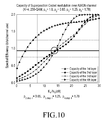
FIG. 10 is a graph illustrating a change in channel capacities of second, third, and fourth layers according to an embodiment of the present disclosure; -
FIGS. 11 and12 are graphs illustrating a change in channel capacities of first, second, third, and fourth layers according to an embodiment of the present disclosure; -
FIG. 13 is a flowchart illustrating a Scalable Video Coding (SVC) method in a broadcasting or communication system according to an embodiment of the present disclosure; and -
FIG. 14 is a graph illustrating improved performance of an SCM scheme according to an embodiment of the present disclosure. - Throughout the drawings, like reference numerals will be understood to refer to like parts, components, and structures.
- The following description with reference to the accompanying drawings is provided to assist in a comprehensive understanding of various embodiments of the present disclosure as defined by the claims and their equivalents. It includes various specific details to assist in that understanding but these are to be regarded as merely exemplary. Accordingly, those of ordinary skill in the art will recognize that various changes and modifications of the various embodiments described herein can be made without departing from the scope and spirit of the present disclosure. In addition, descriptions of well-known functions and constructions may be omitted for clarity and conciseness.
- The terms and words used in the following description and claims are not limited to the bibliographical meanings, but, are merely used by the inventor to enable a clear and consistent understanding of the present disclosure. Accordingly, it should be apparent to those skilled in the art that the following description of various embodiments of the present disclosure is provided for illustration purpose only and not for the purpose of limiting the present disclosure as defined by the appended claims and their equivalents.
- It is to be understood that the singular forms "a," "an," and "the" include plural referents unless the context clearly dictates otherwise. Thus, for example, reference to "a component surface" includes reference to one or more of such surfaces.
-
FIG. 1 is a block diagram of a Superposition Coded Modulation (SCM) encoder having Q independent layers according to an embodiment of the present disclosure. -
FIG. 1 illustrates the structure of an SCM encoder using a Low Density Parity Check (LDPC) code on the assumption of Q independent information layers according to an embodiment of the present disclosure. - Referring to
FIG. 1 , LDPC encoders 101-1 to 101-Q may be readily replaced with other channel encoders. - For the Q layers, an
SCM encoder 110 includes Q modulators 111-1 to 111-Q and Q multipliers 113-1 to 113-Q. The LDPC encoders 101-1 to 101-Q may be configured separately from theSCM encoder 110, as illustrated inFIG. 1 . Alternatively, the LDPC encoders 101-1 to 101-Q may be incorporated into theSCM encoder 110. TheSCM encoder 110 may further include anadder 115 that adds a plurality of signals to generate an output for theSCM encoder 110. For example, theadder 115 may add outputs from the Q multipliers 113-1 to 113-Q. - Referring to
FIG. 1 , for i=1, 2, ..., Q, a jth information word bit bi,j included in an ith layer is input to an ith LDPC encoder. Then, the ith LDPC encoder encodes the information word bit bi,j and provides the coded information bit bi,j to an ith modulator. The ith modulator modulates the coded information bit bi,j and converts the coded information bit bi,j to an ith layer signal xi,j corresponding to an Mi - ary signal constellation. Finally, a jth transmission symbol sj is generated by superposing jth modulation symbols x 1,j , x 2,j , ···, x Q,j of the respective layers byEquation 1.
where di is an SCM coefficient for the ith layer signal x i,j). -
FIGS. 2A, 2B ,3A , and3B illustrate SCM signal constellations according to an embodiment of the present disclosure. - In order to normalize power, a constraint described by
Equation 2 may be imposed depending on system implementation. According to various embodiments of the present disclosure, the SCM coefficient of each layer may be controlled so that the power ratios of the layers may be equal.
- For example, SCM coefficients may be assumed to have a parameter p, and

FIGS. 2A and 2B . A 16-ary signal constellation may be created as illustrated inFIG. 3B by combining the two independent QPSK signals illustrated inFIGS. 2A and 2B , as illustrated inFIG. 3A . - If p=1, an SCM signal constellation corresponding to
FIG. 3A is identical to a typical 16-ary Quadrature Amplitude Modulation (16QAM) signal constellation. - As described above, according to various embodiments of the present disclosure, a modified 16-QAM signal constellation may be obtained by controlling an SCM coefficient p. According to various embodiments of the present disclosure, a different Quality of Service (QoS) level required for each layer may be supported flexibly using a modulation scheme that adopts the modified signal constellation.
- Now, a brief description will be given of the concept of a decoding method in an SCM system.
-
FIG. 4 is a block diagram of an SCM decoder according to an embodiment of the present disclosure. - According to various embodiments of the present disclosure, an SCM coded symbol sj may be assumed to experience an Additive White Gaussian Noise (AWGN) channel. Accordingly, a received signal yj may be expressed as
Equation 3.
- According to various embodiments of the present disclosure, layers may be assumed to be indexed in a descending order of channel reliability in an SCM signal constellation. As an example, a first layer is assumed to have the highest channel reliability and a Qth layer is assumed to have lowest channel reliability. In this case, referring to
FIG. 4 , data of the first to Qth layers are recovered sequentially by (Q-1) interference cancellations through interference cancellers 401-1 to 401-Q-1 and Q LDPC decodings through LDPC decoders 405-1 to 405-Q. - The data recovery operation will be described below in greater detail.
- For example, a first LDPC decoder (LDPC decoder 1) 405-1, a first demapper (demapper 1) 403-1, and a first interference canceller (interference canceller 1) 401-1 may be terminals, for example, portable terminals. In contrast, a second LDPC decoder (LDPC decoder 2) 405-2, a second demapper (demapper 2) 403-2, and a second interference canceller (interference canceller 2) 401-2 may be TVs.
-
Demapper 1 403-1 calculates an input value for decoding inLDPC decoder 1 405-1 in the first layer, from the received signal. The input value may be, for example, a Log Likelihood Ratio (LLR).Demapper 1 403-1 outputs the calculated input value toLDPC decoder 1 405-1.LDPC decoder 1 405-1 determines a hard-decision value of x1,j by LDPC decoding and outputs the determined value to interference canceller 1 401-1.Interference canceller 1 401-1 separates the determined value from the received signal yj using the hard-decision value x̂ 1,j (yj -d 1 x̂ 1,j ). The value yj - d 1 x̂ 1,j is provided todemapper 2 403-1 in the second layer.Demapper 2 403-2 calculates an input value for decoding inLDPC decoder 2 405-2 and then transmits the calculated input value toLDPC decoder 2 405-2.LDPC decoder 2 405-2 performs LDPC decoding in the same manner asLDPC decoder 1 405-1. The demapping, LDPC decoding, and interference cancellation operations are repeated until the last layer. For example, these operations are repeated until LDPC decoding of the last layer is completed. While a plurality of independent processors may be implemented for each of demappers, LDPC decoders, and interference cancellers (up to Q demappers, up to Q LDPC decoders, and up to Q interference cancellers), a demapper, an LDPC decoder, and an interference canceller may be operated for each layer in a single processor because the layers are operated sequentially. - In successive interference cancellation, each layer generally has a different reliability and an error propagation effect occurs, in which an error generated in a previous layer is propagated to a current layer. For example, if the previous layer has an error, the error affects interference cancellation, thus affecting the performance of the current layer. Therefore, if the successive interference cancellation scheme is used as an SCM decoding scheme, the reliability of each layer needs to be controlled such that when the reliability of the previous layer is maximized, the current layer may be decoded.
- To control the reliability of each layer, the coding rate of an LDPC code in each layer may be controlled or the SCM coefficients di described in
Equation 1 may be controlled. Various embodiments of the present disclosure provides a method for supporting various Scalable Video Coding (SVC) schemes by controlling reliability using SCM coefficients, when each layer uses an LDPC code having the same coding rate. - According to various embodiments of the present disclosure, a noise threshold, a channel capacity, or a Signal to Noise Ratio (SNR) corresponding to the channel capacity is used to control the reliability of each layer.
- A noise threshold is a minimum SNR that enables decoding without errors at a given coding rate and in a given modulation scheme. In general, once a channel code is determined, a noise threshold may be determined in many methods. The most popular method for obtaining a noise threshold is density evolution analysis.
- The noise threshold varies with codes. Typically, the reliability of each layer is readily controlled using a channel capacity defined by Shannon. Because the noise threshold is almost close to a channel capacity or an SNR corresponding to the channel capacity of a well-designed code, controlling the reliability of each layer using a channel capacity or an SNR corresponding to the channel capacity may be preferable in many aspects.
- The total channel capacity CTotal of a system that adopts the SCM decoder illustrated in
FIG. 4 in correspondence with the SCM encoder illustrated inFIG. 1 may be determined byEquation 4.
- Similarly, the channel capacity Ci of each layer may be expressed as
Equation 5.

- The use of Equation 6 enables prediction of the reliability of each layer based on a channel capacity or an SNR corresponding to the channel capacity, instead of a noise threshold.
- It may be noted from Equation 6 that the channel capacities Ci may vary with the values of the SCM coefficients d1, d2,···,dQ. For example, in the case in which SCM coefficients have a parameter p,

FIGS. 2A and 2B , the channel capacity of each layer with respect to each p value is calculated as illustrated inFIGS. 5 and6 . -
FIG. 5 is a graph illustrating a channel capacity of an SCM scheme having two independent layers, when p=1.0 according to an embodiment of the present disclosure.FIG. 6 is a graph illustrating a channel capacity of an SCM scheme having two independent layers, when p=0.9 according to an embodiment of the present disclosure. - Referring to
FIGS. 5 and6 , as the value of p becomes smaller, the channel capacity of the first layer decreases and the channel capacity of the second layer increases. Particularly referring toFIG. 6 , if p decreases in a high SNR area, the channel capacity of the second layer may exceed the channel capacity of the first layer (however, because the condition that d1>d2 is generally satisfied, p is set to be larger than
- Because the channel capacity of each layer is changed by controlling the value of p as described above, various SVC schemes may be supported according to the purpose of each communication or broadcasting system.
- Referring to
FIG. 5 , for example, if the SNR of an operation point is 4dB in the communication or broadcasting system, the spectral efficiency of the first layer is about 1.2 and the spectral efficiency of the second layer is about 0.6. For example, the first and second layers have different spectral efficiencies. Therefore, a different amount of data should be transmitted in each layer. - In contrast, referring to
FIG. 6 , if the SNR of the operation point is 4dB, the two layers have an equal spectral efficiency of about 0.9. Accordingly, the same amount of data may be transmitted in each layer. - Therefore, it is noted that the amount of data to be transmitted in each layer may be controlled easily by controlling the value of p according to an intended SVC scheme in a broadcasting or communication system.
- A method for controlling the value of p according to an embodiment of the present disclosure will be described below.
-
FIG. 7 is a graph illustrating a channel capacity of each layer, when 256-ary Quadrature Amplitude Modulation (256-QAM) is used and p1=p2=p3=p4=1.0 according to an embodiment of the present disclosure.FIG. 8 is a graph illustrating a change in channel capacities of third and fourth layers, when 256-QAM is used according to an embodiment of the present disclosure. - First, it is assumed that there are 4 layers ( Q=4 ) and each layer uses 256-QAM. If p1=p2=p3=p4=1 satisfying the constraint described in
Equation 2, d1, d2, d3, and d4 may be expressed as Equation 7 so that an SCM scheme with the four layers combined may be identical to a typical 256-QAM scheme.
- When p1=p2=p3=p4=1.0, satisfying Equation 7, the channel capacity of each layer is illustrated in
FIG. 7 . Referring toFIG. 7 , it is noted that the layers have conspicuously different channel capacities with respect to SNRs. For example, the first and second layers require SNRs of about 3dB and 19dB, respectively with a big difference of about 16dB between them to provide the same spectral efficiency of 1.0. - A description will be given of a method for controlling SCM coefficients, when the same data is to be transmitted in each layer.
- On the assumption that the first and second layers are perfectly decoded, the reliabilities of the third and fourth layers are determined by p3 and p4. Once the coding rate of an LDPC code to be used in the third and fourth layers are determined, p3 and p4 are determined so that the difference between noise thresholds of the third and fourth layers or the difference between SNRs corresponding to channel capacities of the third and fourth layers is less than 0.5dB, while changing p3 under the constraint of
Equation 8.
- For example, if the coding rate of an LDPC code to be used in the third and fourth layers is determined to be 4/9, the theoretical spectral efficiency is 8/9. As illustrated in
FIG. 8 , the channel capacity curves of the third and fourth layers are set to pass through the spectral efficiency of 8/9 by controlling p3 to 0.91. - The reason for setting the difference between SNRs corresponding to channel capacities to about 0.5dB is that in the presence of a plurality of layers, the reliability of a first decoded layer should be higher than that of a next decoded layer in order to reduce the error propagation effect, as described before. In other words, the noise threshold of the first decoded layer should be lower than that of the next decoded layer. This means that the channel capacity of the first decoded layer should be higher than that of the next decoded layer. Although a difference of about 0.5dB is set between SNRs corresponding to channel capacities in the embodiment of the present disclosure, the difference may be changed appropriately under circumstances.
-
FIG. 9 is a graph illustrating a change in channel capacities of second, third, and fourth layers according to an embodiment of the present disclosure.FIG. 10 is a graph illustrating a change in channel capacities of second, third, and fourth layers according to an embodiment of the present disclosure. - New values of p3 and p4 detected in the foregoing description are assumed to be p3'=0.91 and p4'=1.3, respectively. Now, values of p2, p3, and p4 are detected so that the difference between SNRs corresponding to channel capacities of the second and third layers is less than 0.5dB, while changing p2 as illustrated in
FIGS. 9 and10 under the constraint expressed as Equation 9.
- If p3 and p4 are controlled under the condition of
Equation 8, p2 may be controlled without a change in the average power of a transmission signal, while maintaining a ratio between p3 and p4 detected in a previous operation. If the ratio between p3 and p4 is maintained, the difference between the channel capacities (or noise thresholds) of the third and fourth layers is not changed much even though p2 is controlled. Optimum p2, p3, and p4 detected in this manner are assumed to be p2"=0.85, p3"=1.25, and p4"=1.78, respectively. -
FIGS. 11 and12 are graphs illustrating a change in channel capacities of first, second, third, and fourth layers according to an embodiment of the present disclosure. -
FIG. 11 illustrates the channel capacity curve of each layer under the condition that 256-QAM is used, p1 = 1.0, p2 = 0.85, p3 = 1.25, and p4 = 1.7, andFIG. 12 illustrates the channel capacity curve of each layer under the condition that there are four layers, 256-QAM is used, p1 = 0.82, p2 = 1.20, p3 = 1.76, and p4 = 2.55. - Finally, values of p1, p2, p3, and p4 are detected for use as final SCM coefficients so that the difference between SNRs corresponding to channel capacities of the first and second layers is less than 0.5dB, while changing p1 as illustrated in
FIGS. 11 and12 under the constraint expressed as Equation 10]


- SCM coefficients detected under the constraints of Equation 7 to
Equation 10 keep the difference between SNRs corresponding to channel capacities of layers within 0.5dB, irrespective of the coding rate of an LDPC code used in each layer. In addition, because the SNR corresponding to a channel capacity of each layer may be controlled using only one variable, a signal constellation satisfying an intended channel capacity for each layer may be designed simply even though the number of layers is increased. -
FIG. 13 is a flowchart illustrating an SVC method in a broadcasting or communication system according to an embodiment of the present disclosure. - Referring to
FIG. 13 , a receiver controls a power coefficient p for each layer atoperation 1301. As a result, the channel capacity of each layer or an SNR corresponding to the channel capacity of each layer is changed. For example, atoperation 1303, the channel capacity of each layer may be controlled. As illustrated inFIGS. 8 ,10 , and12 , the channel capacities and/or the SNRs corresponding to the channel capacities of layers become equal at a certain point. In an implementable example, the channel capacity of each layer or the SNR corresponding to the channel capacity may be changed by controlling a coding rate. - Table 1 below lists the results of various embodiments of the present disclosure for obtaining optimized SCM coefficients, when the coding rate of each layer is changed. The left four columns represent the coding rates of the respective layers.
- It is noted from the rightmost column of Table 1 that an actual noise threshold (or an SNR corresponding to a channel capacity) increases from one layer to another layer, but is almost the same across the layers (within a difference of 0.5dB).
Table 1 1st layer 2nd layer 3rd layer 4th layer Signal constellation parameters: p 1 / p 2 / p 3 / p 4 Noise Threshold [sB]: 1st/2nd/3rd/4th layer 1/3 1/3 1/3 1/3 0.77/ 1.21/ 1.91./ 2.99 7.12/ 7.22/ 7.38/ 7.50 2/5 2/5 2/5 2/5 0.80/ 1.21/ 1.82/ 2.73 9.04/ 9.12/ 9.24/ 9.35 4/9 4/9 4/9 4/9 0.82/ 1.20/ 1.76/ 2.65 10.18/ 10.36/ 10.44/ 10.60 3/5 3/5 3/5 3/5 0.89/ 1.16/ 1.54/ 1.98 14.19/ 14.59/ 14.61/ 14.84 2/3 2/3 2/3 2/3 0.91/ 1.14/ 1.42/ 1.76 16.09/ 16.25/ 16.63/ 16.68 11/15 11/15 11/15 11/15 0.93/ 1.12/ 1.32/ 1.55 18.03/ 18.28/ 18.36/ 18.66 7/9 7/9 7/9 7/9 0.94/ 1.10/ 1.26/ 1.46 19.65/ 19.74/ 19.75/ 19.97 8/9 8/9 8/9 8/9 0.98/ 1.03/ 1.10/ 1.21 22.53/ 22.87/ 23.15/ 13.22 -
FIG. 14 is a graph illustrating improved performance of an SCM scheme according to an embodiment of the present disclosure. - Referring to
FIG. 14 , it is noted that compared to a conventional SCM scheme using a fixed 256-QAM signal constellation, the SCM scheme according to various embodiments of the present disclosure can achieve a great performance gain of about 7dB at a point at which a Bit Error Rate (BER) is 10-5. - As is apparent from the above description, various embodiments of the present disclosure can implement an SVC scheme efficiently using an SCM scheme in a broadcasting or communication system.
- Various embodiments of the present disclosure can maximize the performance of each layer in a broadcasting or communication system, if an SCM scheme is used and the coding rate of each layer is determined in the SCM scheme.
- Various embodiments of the present disclosure can maximize the performance by controlling the value of a parameter p in a broadcasting or communication system.
- Various embodiments of the present disclosure can flexibly support different QoS requirements of layers using a modulation scheme based on a modified signal constellation.
- The proposed method and apparatus according to various embodiments of the present disclosure for performing an SCM scheme in a broadcasting or communication system may be implemented as computer-readable code in a non-transitory computer-readable recording medium. The non-transitory computer-readable recording medium may include any kind of recording device storing computer-readable data. Examples of the recording medium may include Read Only Memory (ROM), Random Access Memory (RAM), optical disk, magnetic tape, floppy disk, hard disk, non-volatile memory, and the like, and may also include the medium that is implemented in the form of carrier waves (e.g., transmission over the Internet). In addition, the non-transitory computer-readable recording medium may be distributed over the computer systems connected over the network, and computer-readable codes may be stored and executed in a distributed manner.
- Although the present disclosure has been shown and described with reference to various embodiments thereof, it will be understood by those skilled in the art that various changes in form and details may be made therein without departing from the spirit and scope of the present disclosure as defined by the appended claims and their equivalents.
Claims (14)
- A method for performing a Superposition Coded Modulation (SCM) scheme in a broadcasting or communication system including a controller, the method comprising:controlling an SCM coefficient t by the controller,wherein the SCM coefficient is controlled according to a channel capacity of each layer of one or more layers in which information included in a signal is encoded.
- A method for processing a Superposition Coded Modulation (SCM) signal in a broadcasting or communication system including a controller, the method comprising:receiving a signal from a transmitter; andperforming demapping, Low Density Parity Check (LDPC) decoding, and interference cancellation on the signal in each layer of one or more layers in which information included in the signal is encoded,wherein an SCM coefficient is controlled for the signal by the transmitter, andwherein the SCM coefficient is controlled according to a channel capacity of each layer of the one or more layers.
- The method of claim 1 or the method of claim 2, wherein the SCM coefficient is controlled to make a power ratio of each layer a predetermined value.
- The method of claim 1 or the method of claim 2, wherein the SCM coefficient is controlled to make a Signal-to-Noise Ratio (SNR) corresponding to the channel capacity equal.
- The method of claim 1 or the method of claim 2, wherein the SCM coefficient is controlled within a difference of 0.5dB between SNRs corresponding to channel capacities of layers.
- The method of claim 1 or the method of claim 2, wherein the SCM coefficient is controlled to change a noise threshold.
- The method of claim 1 or the method of claim 2, wherein the SCM coefficient is controlled within an SNR corresponding to the channel capacity according to a coding rate.
- An apparatus for performing a Superposition Coded Modulation (SCM) scheme in a broadcasting or communication system including a controller, the apparatus comprising:a controller configured to control an SCM coefficient,wherein the controller controls the SCM coefficient according to a channel capacity of each layer of one or more layers in which information included in a signal is encoded.
- An apparatus for processing a Superposition Coded Modulation (SCM) signal in a broadcasting or communication system including a controller, the apparatus comprising:a receiver configured to receive a signal from a transmitter; anda controller configured to perform demapping, Low Density Parity Check (LDPC) decoding, and interference cancellation on the signal in each layer of one or more layers in which the information included in the signal is encoded,wherein an SCM coefficient is controlled for the signal by the transmitter, andwherein the SCM coefficient is controlled according to a channel capacity of each layer of the one or more layers.
- The apparatus of claim 8 or the apparatus of claim 9, wherein the controller controls the SCM coefficient to make a power ratio of each layer a predetermined value.
- The apparatus of claim 8 or the apparatus of claim 9, wherein the controller controls the SCM coefficient to make a Signal-to-Noise Ratio (SNR) corresponding to the channel capacity equal.
- The apparatus of claim 8 or the apparatus of claim 9, wherein the controller controls the SCM coefficient within a difference of 0.5dB between SNRs corresponding to channel capacities of layers.
- The apparatus of claim 8 or the apparatus of claim 9, wherein the controller controls the SCM coefficient to change a noise threshold.
- The apparatus of claim 8 or the apparatus of claim 9, wherein the SCM coefficient is controlled within an SNR corresponding to the channel capacity according to a coding rate.
Applications Claiming Priority (1)
| Application Number | Priority Date | Filing Date | Title |
|---|---|---|---|
| KR1020130140704A KR102384585B1 (en) | 2013-11-19 | 2013-11-19 | Apparatus and method for scalble video coding in broadcast or communication system |
Publications (1)
| Publication Number | Publication Date |
|---|---|
| EP2876833A1 true EP2876833A1 (en) | 2015-05-27 |
Family
ID=51947174
Family Applications (1)
| Application Number | Title | Priority Date | Filing Date |
|---|---|---|---|
| EP14193765.6A Withdrawn EP2876833A1 (en) | 2013-11-19 | 2014-11-18 | Method and apparatus for performing superposition coded modulation scheme in a broadcasting or communication system |
Country Status (3)
| Country | Link |
|---|---|
| US (3) | US10015500B2 (en) |
| EP (1) | EP2876833A1 (en) |
| KR (3) | KR102384585B1 (en) |
Cited By (3)
| Publication number | Priority date | Publication date | Assignee | Title |
|---|---|---|---|---|
| CN106254036A (en) * | 2016-08-18 | 2016-12-21 | 重庆邮电大学 | A kind of detection method being layered under supercomposed coding generalized spatial modulation system |
| CN108886418A (en) * | 2016-03-30 | 2018-11-23 | 松下电器(美国)知识产权公司 | Receiving device and receiving method |
| CN109565349A (en) * | 2016-08-12 | 2019-04-02 | 松下电器(美国)知识产权公司 | Receiving device and receiving method |
Families Citing this family (2)
| Publication number | Priority date | Publication date | Assignee | Title |
|---|---|---|---|---|
| JP6668686B2 (en) * | 2015-11-02 | 2020-03-18 | ソニー株式会社 | Transmission device |
| US11539557B1 (en) * | 2021-12-16 | 2022-12-27 | Qualcomm Incorporated | Multi-level coding for power efficient channel coding |
Citations (1)
| Publication number | Priority date | Publication date | Assignee | Title |
|---|---|---|---|---|
| WO2010019018A2 (en) * | 2008-08-14 | 2010-02-18 | Electronics And Telecommunications Research Institute | Apparatus for transmitting and receiving digital multimedia broadcasting and method thereof |
Family Cites Families (19)
| Publication number | Priority date | Publication date | Assignee | Title |
|---|---|---|---|---|
| US10277290B2 (en) * | 2004-04-02 | 2019-04-30 | Rearden, Llc | Systems and methods to exploit areas of coherence in wireless systems |
| JP4777440B2 (en) * | 2006-02-01 | 2011-09-21 | エルジー エレクトロニクス インコーポレイティド | Data transmission / reception method using superposition modulation in wireless communication system |
| US8085819B2 (en) | 2006-04-24 | 2011-12-27 | Qualcomm Incorporated | Superposition coding in a wireless communication system |
| TWI420865B (en) * | 2006-04-25 | 2013-12-21 | Lg Electronics Inc | A method of configuring multiuser packet and a structure thereof in a wireless communication system |
| CN101601290B (en) * | 2006-12-06 | 2012-02-08 | 韩国电子通信研究院 | Apparatus and method for digital multimedia broadcasting service |
| CN101939931A (en) * | 2007-09-28 | 2011-01-05 | 何品翰 | Robust system and method for wireless data multicasting using superposition modulation |
| CN101494629A (en) * | 2008-01-24 | 2009-07-29 | 华为技术有限公司 | Method and apparatus for obtaining symbol mapping diversity, generating star map and modulation |
| WO2009134082A2 (en) | 2008-04-29 | 2009-11-05 | Electronics And Telecommunications Research Institute | Apparatus and method for transmitting data using multiple antenna for single carrier frequency division multiple access system |
| US8199836B2 (en) * | 2008-05-02 | 2012-06-12 | Nec Laboratories America, Inc. | Multi-resolution precoding codebook |
| DE102008029353A1 (en) * | 2008-06-20 | 2009-12-31 | Fraunhofer-Gesellschaft zur Förderung der angewandten Forschung e.V. | Apparatus for assigning and estimating transmission symbols |
| US8811267B2 (en) | 2008-08-13 | 2014-08-19 | Samsung Electronics Co., Ltd. | Communication system for supporting primary user and secondary user |
| CN104660534B (en) * | 2008-09-18 | 2018-02-09 | 三菱电机株式会社 | Dispensing device and reception device |
| CN102301819B (en) * | 2008-11-21 | 2015-01-07 | 皮恩-汉·霍 | System, method and computer program for single modulation scheme superposition coding multicast |
| US8649456B2 (en) * | 2009-03-12 | 2014-02-11 | Futurewei Technologies, Inc. | System and method for channel information feedback in a wireless communications system |
| US8369451B2 (en) * | 2009-06-09 | 2013-02-05 | Adeptence, Llc | Method and apparatus for constant envelope modulation |
| US8438461B2 (en) * | 2009-10-12 | 2013-05-07 | Marvell World Trade Ltd. | Power consumption in LDPC decoder for low-power applications |
| TWI380598B (en) * | 2010-05-18 | 2012-12-21 | Univ Nat Taiwan | Programmable ldpc code decoder and decoding method thereof |
| US8537738B2 (en) * | 2010-11-18 | 2013-09-17 | Nec Laboratories America, Inc. | Method and a system of video multicast scheduling |
| US9503203B2 (en) * | 2013-06-11 | 2016-11-22 | Intel Corporation | Wireless interference cancellation |
-
2013
- 2013-11-19 KR KR1020130140704A patent/KR102384585B1/en active Active
-
2014
- 2014-11-18 US US14/546,488 patent/US10015500B2/en not_active Expired - Fee Related
- 2014-11-18 EP EP14193765.6A patent/EP2876833A1/en not_active Withdrawn
-
2018
- 2018-05-18 US US15/983,608 patent/US11032558B2/en active Active
-
2021
- 2021-06-04 US US17/339,497 patent/US11611766B2/en active Active
-
2022
- 2022-04-05 KR KR1020220042054A patent/KR102570656B1/en active Active
-
2023
- 2023-08-21 KR KR1020230109373A patent/KR102766353B1/en active Active
Patent Citations (1)
| Publication number | Priority date | Publication date | Assignee | Title |
|---|---|---|---|---|
| WO2010019018A2 (en) * | 2008-08-14 | 2010-02-18 | Electronics And Telecommunications Research Institute | Apparatus for transmitting and receiving digital multimedia broadcasting and method thereof |
Non-Patent Citations (6)
| Title |
|---|
| HUGO MERIC ET AL: "Generic approach for hierarchical modulation performance analysis: Application to DVB-SH", WIRELESS TELECOMMUNICATIONS SYMPOSIUM (WTS), 2011, IEEE, 13 April 2011 (2011-04-13), pages 1 - 6, XP031903509, ISBN: 978-1-4577-0162-7, DOI: 10.1109/WTS.2011.5960857 * |
| JING LEI ET AL: "A Backward-Compatible Solution for Next Generation DVB-C System", IEEE INTERNATIONAL CONFERENCE ON COMMUNICATIONS, 2008 : ICC '08 ; 19 - 23 MAY 2008, BEIJING, CHINA, IEEE, PISCATAWAY, NJ, USA, 19 May 2008 (2008-05-19), pages 1962 - 1966, XP031265697, ISBN: 978-1-4244-2075-9 * |
| MCCLOUD M ET AL: "Equal rate multilevel coding for the awgn channel", SIGNAL PROCESSING ADVANCES IN WIRELESS COMMUNICATIONS, 2005 IEEE 6TH W ORKSHOP ON NEW YORK, NY, USA JUNE 2-8, 2005, PISCATAWAY, NJ, USA,IEEE, 2 June 2005 (2005-06-02), pages 610 - 614, XP010834532, ISBN: 978-0-7803-8867-3, DOI: 10.1109/SPAWC.2005.1506212 * |
| TAHIR Y H ET AL: "Unequal error protection for wireless data transmission using superposition coding with feedback", INNOVATIONS IN INFORMATION TECHNOLOGY, 2008. IIT 2008. INTERNATIONAL CONFERENCE ON, IEEE, PISCATAWAY, NJ, USA, 16 December 2008 (2008-12-16), pages 426 - 429, XP031424069, ISBN: 978-1-4244-3396-4 * |
| VAZQUEZ-ARAUJO F J: "Approaching the MIMO capacity with Superposition Coded Modulation", TURBO CODES AND ITERATIVE INFORMATION PROCESSING (ISTC), 2010 6TH INTERNATIONAL SYMPOSIUM ON, IEEE, PISCATAWAY, NJ, USA, 6 September 2010 (2010-09-06), pages 299 - 303, XP031783839, ISBN: 978-1-4244-6744-0 * |
| YOUZHE FAN ET AL: "Rate and Power Allocation for 2-Level Superposition Coded Modulation Supporting Both Unicast and Multicast Traffic", 2012 8TH INTERNATIONAL CONFERENCE ON WIRELESS COMMUNICATIONS, NETWORKING AND MOBILE COMPUTING (WICOM 2012) : SHANGHAI, CHINA, 21 - 23 SEPTEMBER 2012, IEEE, PISCATAWAY, NJ, 21 September 2012 (2012-09-21), pages 1 - 5, XP032342853, ISBN: 978-1-61284-684-2, DOI: 10.1109/WICOM.2012.6478632 * |
Cited By (13)
| Publication number | Priority date | Publication date | Assignee | Title |
|---|---|---|---|---|
| US10396938B2 (en) | 2016-03-30 | 2019-08-27 | Panasonic Intellectual Property Corporation Of America | Reception device and reception method |
| CN108886418A (en) * | 2016-03-30 | 2018-11-23 | 松下电器(美国)知识产权公司 | Receiving device and receiving method |
| EP3439209A4 (en) * | 2016-03-30 | 2019-04-17 | Panasonic Intellectual Property Corporation of America | RECEIVING DEVICE AND RECEIVING METHOD |
| EP3518484A1 (en) * | 2016-03-30 | 2019-07-31 | Panasonic Intellectual Property Corporation of America | Transmission device, reception device, transmission method and reception method |
| US10608783B2 (en) | 2016-03-30 | 2020-03-31 | Panasonic Intellectual Property Corporation Of America | Reception device and reception method |
| CN108886418B (en) * | 2016-03-30 | 2020-08-04 | 松下电器(美国)知识产权公司 | Receiving apparatus and receiving method |
| CN111786926A (en) * | 2016-03-30 | 2020-10-16 | 松下电器(美国)知识产权公司 | Receiving device, receiving method, transmitting device and transmitting method |
| US11349603B2 (en) | 2016-03-30 | 2022-05-31 | Panasonic Intellectual Property Corporation Of America | Reception device and reception method |
| US11515965B2 (en) | 2016-03-30 | 2022-11-29 | Panasonic Intellectual Property Corporation Of America | Reception device and reception method |
| CN111786926B (en) * | 2016-03-30 | 2023-05-09 | 松下电器(美国)知识产权公司 | Receiving device, receiving method, sending device and sending method |
| CN109565349A (en) * | 2016-08-12 | 2019-04-02 | 松下电器(美国)知识产权公司 | Receiving device and receiving method |
| CN106254036B (en) * | 2016-08-18 | 2019-07-19 | 重庆邮电大学 | A kind of detection method being layered under supercomposed coding generalized spatial modulation system |
| CN106254036A (en) * | 2016-08-18 | 2016-12-21 | 重庆邮电大学 | A kind of detection method being layered under supercomposed coding generalized spatial modulation system |
Also Published As
| Publication number | Publication date |
|---|---|
| KR102766353B1 (en) | 2025-02-13 |
| US11032558B2 (en) | 2021-06-08 |
| US20150139294A1 (en) | 2015-05-21 |
| KR102570656B1 (en) | 2023-08-25 |
| KR20150057385A (en) | 2015-05-28 |
| US20180270491A1 (en) | 2018-09-20 |
| US20210297683A1 (en) | 2021-09-23 |
| US10015500B2 (en) | 2018-07-03 |
| KR20220050105A (en) | 2022-04-22 |
| KR102384585B1 (en) | 2022-04-11 |
| KR20230124882A (en) | 2023-08-28 |
| US11611766B2 (en) | 2023-03-21 |
Similar Documents
| Publication | Publication Date | Title |
|---|---|---|
| US11611766B2 (en) | Method and apparatus for performing superposition coded modulation scheme in a broadcasting or communication system | |
| US10211952B2 (en) | Scheme for communication using integer-forcing scheme in wireless communication system | |
| US8498357B2 (en) | Transmitting/receiving apparatus and method for interleaver division multiple access system | |
| RU2609067C2 (en) | Method and apparatus for transmitting and receiving information in broadcasting/communication system | |
| US7389464B2 (en) | Apparatus and method for encoding and decoding a space-time low density parity check code with full diversity gain | |
| US8942257B2 (en) | Wireless network using feedback of side information and communication method using network coding | |
| US8270543B1 (en) | Scaling and quantization of soft decoding metrics | |
| US8219874B2 (en) | Multi-dimensional LDPC coded modulation for high-speed optical transmission systems | |
| KR100719840B1 (en) | Space-time frequency block encoding apparatus and method | |
| US20150071640A1 (en) | Coded Modulation for Small Step-Size Variable Spectral Efficiency | |
| US10135649B2 (en) | Systems and methods for performing multi-level coding in a discrete multitone modulation communication system | |
| US20240073066A1 (en) | Devices and methods for a dirty paper coding scheme | |
| US20090245432A1 (en) | Communication system | |
| EP2894804A1 (en) | Apparatus and method for adaptively selecting channel code based on non-gaussianity of channel in wireless communication system | |
| US8520759B2 (en) | Apparatus and method for detecting signal based on lattice reduction to support different coding scheme for each stream in multiple input multiple output wireless communication system | |
| US9367387B2 (en) | Rate adaptive irregular QC-LDPC codes from pairwise balanced designs for ultra-high-speed optical transports | |
| US10567016B2 (en) | Transmission device, reception device, transmission method, and reception method | |
| US11283664B2 (en) | Reception device and reception method | |
| CN107104759B (en) | Method and decoding apparatus for decoding a signal in a multi-antenna system | |
| US20130251075A1 (en) | Soft decision bit detection and demodulation method for digital modulation method | |
| CN107277566B (en) | Signaling coding modulation method and demodulation decoding method based on superposition coding | |
| WO2026105289A1 (en) | Decoding circuit, reception device, and decoding method | |
| KR101413411B1 (en) | A soft decision Viterbi algorithm channel equalization method and receiver using the same | |
| KR101444945B1 (en) | Apparatus and method for the most suitable power allocatin in the orthogonalized spatial multiplexing system | |
| KR20090079402A (en) | Transmission Method of Multiple Antenna System Using LDPC Coder |
Legal Events
| Date | Code | Title | Description |
|---|---|---|---|
| PUAI | Public reference made under article 153(3) epc to a published international application that has entered the european phase |
Free format text: ORIGINAL CODE: 0009012 |
|
| 17P | Request for examination filed |
Effective date: 20141118 |
|
| AK | Designated contracting states |
Kind code of ref document: A1 Designated state(s): AL AT BE BG CH CY CZ DE DK EE ES FI FR GB GR HR HU IE IS IT LI LT LU LV MC MK MT NL NO PL PT RO RS SE SI SK SM TR |
|
| AX | Request for extension of the european patent |
Extension state: BA ME |
|
| R17P | Request for examination filed (corrected) |
Effective date: 20151126 |
|
| RBV | Designated contracting states (corrected) |
Designated state(s): AL AT BE BG CH CY CZ DE DK EE ES FI FR GB GR HR HU IE IS IT LI LT LU LV MC MK MT NL NO PL PT RO RS SE SI SK SM TR |
|
| STAA | Information on the status of an ep patent application or granted ep patent |
Free format text: STATUS: EXAMINATION IS IN PROGRESS |
|
| 17Q | First examination report despatched |
Effective date: 20181206 |
|
| STAA | Information on the status of an ep patent application or granted ep patent |
Free format text: STATUS: THE APPLICATION IS DEEMED TO BE WITHDRAWN |
|
| 18D | Application deemed to be withdrawn |
Effective date: 20250218 |