EP2876781A1 - Electrical machine with improved cooling - Google Patents
Electrical machine with improved cooling Download PDFInfo
- Publication number
- EP2876781A1 EP2876781A1 EP13194013.2A EP13194013A EP2876781A1 EP 2876781 A1 EP2876781 A1 EP 2876781A1 EP 13194013 A EP13194013 A EP 13194013A EP 2876781 A1 EP2876781 A1 EP 2876781A1
- Authority
- EP
- European Patent Office
- Prior art keywords
- component
- lamination
- recesses
- corrugated layer
- electrical machine
- Prior art date
- Legal status (The legal status is an assumption and is not a legal conclusion. Google has not performed a legal analysis and makes no representation as to the accuracy of the status listed.)
- Granted
Links
- 238000001816 cooling Methods 0.000 title claims abstract description 10
- 238000003475 lamination Methods 0.000 claims description 47
- 238000000034 method Methods 0.000 claims description 10
- 239000012809 cooling fluid Substances 0.000 claims description 7
- 229910052751 metal Inorganic materials 0.000 abstract description 8
- 239000002184 metal Substances 0.000 abstract description 8
- 150000002739 metals Chemical class 0.000 abstract description 6
- 239000012530 fluid Substances 0.000 description 6
- 230000001360 synchronised effect Effects 0.000 description 6
- ZZUFCTLCJUWOSV-UHFFFAOYSA-N furosemide Chemical compound C1=C(Cl)C(S(=O)(=O)N)=CC(C(O)=O)=C1NCC1=CC=CO1 ZZUFCTLCJUWOSV-UHFFFAOYSA-N 0.000 description 5
- 238000009826 distribution Methods 0.000 description 3
- 238000000926 separation method Methods 0.000 description 3
- 230000015572 biosynthetic process Effects 0.000 description 2
- 238000004519 manufacturing process Methods 0.000 description 2
- 239000000463 material Substances 0.000 description 2
- 229910001369 Brass Inorganic materials 0.000 description 1
- 229910052782 aluminium Inorganic materials 0.000 description 1
- XAGFODPZIPBFFR-UHFFFAOYSA-N aluminium Chemical compound [Al] XAGFODPZIPBFFR-UHFFFAOYSA-N 0.000 description 1
- 239000010951 brass Substances 0.000 description 1
- 239000002826 coolant Substances 0.000 description 1
- 230000001419 dependent effect Effects 0.000 description 1
- 230000000694 effects Effects 0.000 description 1
- 238000002347 injection Methods 0.000 description 1
- 239000007924 injection Substances 0.000 description 1
- 238000003780 insertion Methods 0.000 description 1
- 230000037431 insertion Effects 0.000 description 1
- 238000012986 modification Methods 0.000 description 1
- 230000004048 modification Effects 0.000 description 1
- 125000006850 spacer group Chemical group 0.000 description 1
- 229910001220 stainless steel Inorganic materials 0.000 description 1
- 239000010935 stainless steel Substances 0.000 description 1
- 238000009423 ventilation Methods 0.000 description 1
- XLYOFNOQVPJJNP-UHFFFAOYSA-N water Substances O XLYOFNOQVPJJNP-UHFFFAOYSA-N 0.000 description 1
- 238000003466 welding Methods 0.000 description 1
- 238000004804 winding Methods 0.000 description 1
Images




Classifications
-
- H—ELECTRICITY
- H02—GENERATION; CONVERSION OR DISTRIBUTION OF ELECTRIC POWER
- H02K—DYNAMO-ELECTRIC MACHINES
- H02K1/00—Details of the magnetic circuit
- H02K1/06—Details of the magnetic circuit characterised by the shape, form or construction
- H02K1/12—Stationary parts of the magnetic circuit
- H02K1/20—Stationary parts of the magnetic circuit with channels or ducts for flow of cooling medium
-
- H—ELECTRICITY
- H02—GENERATION; CONVERSION OR DISTRIBUTION OF ELECTRIC POWER
- H02K—DYNAMO-ELECTRIC MACHINES
- H02K1/00—Details of the magnetic circuit
- H02K1/06—Details of the magnetic circuit characterised by the shape, form or construction
- H02K1/22—Rotating parts of the magnetic circuit
- H02K1/32—Rotating parts of the magnetic circuit with channels or ducts for flow of cooling medium
Definitions
- the electric machine is in particular a rotating electric machine such as a synchronous generator to be connected to a gas or steam turbine (Turbogenerator) or a synchronous generator to be connected to a hydro turbine (hydro generator) or an asynchronous generator or a synchronous or asynchronous electric motor or also other types of electric machines.
- a rotating electric machine such as a synchronous generator to be connected to a gas or steam turbine (Turbogenerator) or a synchronous generator to be connected to a hydro turbine (hydro generator) or an asynchronous generator or a synchronous or asynchronous electric motor or also other types of electric machines.
- the present disclosure relates to an electrical machine, and more in particular it relates to a component thereof.
- the electric machine is in particular a rotating electric machine such as a synchronous generator to be connected to a gas or steam turbine (turbo generator) or a synchronous generator to be connected to a hydro turbine (hydro generator) or an asynchronous generator or a synchronous or asynchronous electric motor or also other types of electric machines.
- cooling ducts are needed.
- the ducts are generally created by distance pieces between the sheet metals.
- the aforementioned distance pieces are replaced by deformed sheet metals.
- the surface in contact to the cooling air can be increased. This leads to a better cooling.
- the component 1 comprises a plurality of stacked laminations 11, which are generally used to assemble stator cores or used to for forming poles mounted on the rotor.
- the stacked laminations 11, in order to satisfy the important need of providing a suitable cooling system therein, comprise distance means in the form of longitudinal elements, schematically represented in the figure and denoted with reference 12, which are usually welded between a pair of adjacent stacks 13a and 13b.
- distance means 12 is welded on a top lamination 131b of the stack 13b and on a bottom lamination 131a of the stack 13a to create a separation between the stack, thus allowing a cooling fluid to flow therein and provide heat removal.
- lamination stack 11 may comprise a plurality of layers of adjacent lamination stacks, in pair separated by welded distance means as explained above.
- the amount of stacks assembled will vary depending on the particular machine to manufacture based on the required power to be supplied.
- Figure 2 shows a planar view of the top lamination 131b as described above.
- the figure shows longitudinal elements 12 welded on the surface of the lamination 131b creating separation between the latter and the opposed lamination (not shown).
- Figure 2A shows an axial section of the longitudinal element 12.
- the component 2 comprises a plurality of stacked laminations 21.
- the component 2 comprises a corrugated layer 22 which is interposed between a pair of adjacent stacks 23a and 23b.
- the corrugated layer 22 provides a separation means between the stacks 23a and 23b. This way, a plurality of passageways 7 are formed between the stacks 23a and 23b for the passage of a cooling fluid, when the rotating machine is assembled and in operation.
- the corrugated layer comprises a first lamination 221, positioned on top of the stack 23b, which is deformed in such a way to define on its surface first recesses 222.
- first recesses 222 are in the form of longitudinal ducts, having a rectangular section. Other shapes may also be considered, like a trapezoidal one.
- Different process may be chosen for acquiring the first recesses 222 on the first lamination 221.
- An advantageous one is the forming process, in particular hydroforming. Hydroforming process allows the formation of particular shapes on ductile metals such as aluminum, brass or stainless steel by insertion of the laminate in a chamber comprising a mold and an aperture for the injection of a fluid. High pressure hydraulic pumps then inject fluid at high pressure inside the chamber which causes the laminate to expand until it matches the mold. Such process is generally used in the automotive industry. As this process is known in the art, it won't be herewith further described.
- the component 3 comprises the plurality of stacked lamination 21 comprising a pair of adjacent lamination stacks 23a and 23b.
- a corrugated layer 32 is interposed there between by means of lamination 221 deformed in such a way to obtain first recesses 222.
- the corrugated layer 32 defines passageways 7 for the coolant fluid.
- the first recesses 222 are in this example in the form in longitudinal ducts, having in this embodiment a trapezoidal section. It will be appreciated that a rectangular section could be used instead.
- the corrugated layer 32 comprises a second lamination, indicated in the figure with numeral reference 321, disposed adjacent to the first lamination and deformed as well in such a way to define on its surface a plurality of second recesses 322.
- recesses 222 and 322 have identical sections.
- First and second laminations 221 and 321 are disposed such that first and second recesses 222 and 322 have aligned convexities and such that each second recess 322 is at least partially hosted into a correspondent first recess 222.
- This configuration is particularly advantageous because it strengthens the mechanical stiffness and stability of the stacked lamination, especially in correspondence of the channels for the passage of cooling fluid.
- trapezoidal section for the ducts formed on the lamination is particularly preferred as such section assures a minor mechanical stress on the material, which then guarantees a more reliable behaviour while in operation.
- the component 4 comprises a pair of adjacent stacks 23a and 23b and a corrugated layer 42.
- the corrugated layer 42 comprises the first lamination 221 disposed on top of the stack 23b deformed as to define first recesses 222 having a form of longitudinal ducts (in this example having a substantially rectangular section).
- the corrugated layer comprises a third lamination 421, in turn deformed in a way to define on its surface third recesses 422.
- first and third recesses have identical sections.
- first lamination 221 is opposite with respect to third lamination 421 and disposed such that first and third recesses 222 and 422 have opposite convexities and each first recess abuts on a correspondent third recess.
- This configuration is particularly advantageous because it assures a homogeneous distribution of the pressures involved in the lamination stacks during operation.
- the third embodiment may have first recesses 222 formed by a couple of laminations disposed as taught with reference to the second embodiment.
- the component 5 comprises a pair of adjacent stacks 23a and 23b and a corrugated layer 52.
- This embodiment differs from the preceding ones in the fact that on a first lamination 521 the recesses are in the form of a plurality of dimples, indicated in the figure with the reference number 522.
- dimples passageways 7 are configured as a plurality of possible paths which the fluid can pass through.
- the corrugated layer 52 may comprise a second lamination 531 opposite to the first lamination 521, the two laminations having correspondent dimples disposed with opposite convexities such that each dimple of the first lamination 521 abuts on a correspondent dimple 532, formed on second lamination 531.
- each dimple on the stack may be formed by two laminations as described, mutatis mutandis, concerning second embodiment.
- each dimple may be hollow inside and comprise an opening 5221 configured to allow passage of the cooling fluid inside the dimple. This way, the surface for the heat exchange is greatly increased, thus greatly improving the process of heat removal.
- Figure 8 illustrates a planar view of a corrugated layer 62 comprising a lamination 621 including a top portion having recesses in the form of a plurality of dimples, and lower portions characterized by recesses 222 in the form of longitudinal ducts.
- the dimples are advantageous because, differently from longitudinal ducts, they don't provide preferred passageways for the flow of the cooling fluid but rather a plurality of possible channels where the fluid can be distributed.
- the presence of windings 20 cause a reduction of the available space for forming dimples, and therefore the formation longitudinal ducts completes the distribution of recesses on the lamination. This way it is assured a total coverage of the lamination for establishing the corrugated layer and thus a highly effective passage of cooling fluid for heat removal.
- the fluid is not restricted to air only.
Landscapes
- Engineering & Computer Science (AREA)
- Power Engineering (AREA)
- Motor Or Generator Cooling System (AREA)
- Secondary Cells (AREA)
Abstract
Description
- The electric machine is in particular a rotating electric machine such as a synchronous generator to be connected to a gas or steam turbine (Turbogenerator) or a synchronous generator to be connected to a hydro turbine (hydro generator) or an asynchronous generator or a synchronous or asynchronous electric motor or also other types of electric machines.
- The present disclosure relates to an electrical machine, and more in particular it relates to a component thereof. The electric machine is in particular a rotating electric machine such as a synchronous generator to be connected to a gas or steam turbine (turbo generator) or a synchronous generator to be connected to a hydro turbine (hydro generator) or an asynchronous generator or a synchronous or asynchronous electric motor or also other types of electric machines.
- At air cooled generators, in particular hydro generators, all incidental losses have to be transferred via convection to the cooling air. A certain amount of cooling air and a defined distribution is needed to keep the temperature of the machine below the critical temperature level.
- To ensure that the volume flow can circulate through the machine, in some parts of the machine (e.g. in the stator core (including yoke) and rotor rim for asynchronous machines) cooling ducts are needed. In the stacked parts of the machine the ducts are generally created by distance pieces between the sheet metals.
- However, an important amount of distance keepers are needed to create the ventilation ducts. All of them have to be fixed on the sheet metal. This is needed for mounting them and to avoid unwished movement during operation. Especially on the rotor side, due to centrifugal forces, the fixation can be challenging, established by form closure.
- Creating the ducts with distance pieces entails a lot of additional parts and work.
- It is an object of the present invention to overcome said disadvantages with reference to the state of the art providing a component for an electrical machine as substantially defined in
independent claim 1. - It is a further object of the present invention to provide an electrical machine as substantially defined in
dependent claim 12. - As it will appear clear from the detailed description of some exemplary, and not limiting, embodiments of the invention, the aforementioned distance pieces are replaced by deformed sheet metals.
- This provides the advantageous technical effects of a reduced number of single parts; no additional individual production step for mounting the distance pieces on the sheet metal; no danger that single parts detach during mounting or operation and an improved stiffness of the structure.
- Furthermore, a three dimensional design allows the possibility of locally varying the mechanical stiffness, which also implies that non homogeneous structures could also be implemented.
- Depending on the shape of the deformed sheet metals, the surface in contact to the cooling air can be increased. This leads to a better cooling.
- The foregoing objects and many of the attendant advantages of this invention will become more readily appreciated as the same becomes better understood by reference to the following detailed description when taken in conjunction with the accompanying drawings, wherein:
-
Fig. 1 is a prospective view of a component for an electrical machine comprising a plurality of stacked laminations according to the prior art; -
Fig. 2 is radial section of the component ofFig. 1 ; -
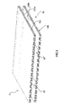
Fig. 3 is a prospective view of a first preferred embodiment of a component for an electrical machine according to the present invention; -
Fig. 4 is a prospective view of a second preferred embodiment of a component for an electrical machine according to the present invention; -
Fig. 5 is a prospective view of a third preferred embodiment of a component for an electrical machine according to the present invention; -
Fig. 6 is a prospective view of a forth preferred embodiment of a component for an electrical machine according to the present invention; -
Fig. 7 shows a particular of the component ofFig. 6 ; and -
Fig. 8 is a prospective view of a fifth preferred embodiment of a component for an electrical machine according to the present invention. - With now reference to
Figure 1 , it is illustrated a component for anelectrical machine 1 according to the prior art. Thecomponent 1 comprises a plurality of stackedlaminations 11, which are generally used to assemble stator cores or used to for forming poles mounted on the rotor. The stackedlaminations 11, in order to satisfy the important need of providing a suitable cooling system therein, comprise distance means in the form of longitudinal elements, schematically represented in the figure and denoted withreference 12, which are usually welded between a pair ofadjacent stacks top lamination 131b of thestack 13b and on abottom lamination 131a of thestack 13a to create a separation between the stack, thus allowing a cooling fluid to flow therein and provide heat removal. - It will be appreciated that
lamination stack 11 may comprise a plurality of layers of adjacent lamination stacks, in pair separated by welded distance means as explained above. The amount of stacks assembled will vary depending on the particular machine to manufacture based on the required power to be supplied. - As stated above, the assembly of such component, because of the presence of welded distance means, requires great effort because the welding procedure requires time and also has to be operated properly. In fact, it is of paramount importance avoiding the movement of the welded spacers while the machine is in use, especially for the ones mounted on the rotor where important centrifugal forces are involved during operation.
-
Figure 2 shows a planar view of thetop lamination 131b as described above. The figure showslongitudinal elements 12 welded on the surface of thelamination 131b creating separation between the latter and the opposed lamination (not shown). -
Figure 2A shows an axial section of thelongitudinal element 12. - With now reference to the next
Figure 3 , it is shown a prospective view of acomponent 2 according to a first preferred embodiment of the present invention. - The
component 2 comprises a plurality ofstacked laminations 21. In particular, thecomponent 2 comprises acorrugated layer 22 which is interposed between a pair ofadjacent stacks corrugated layer 22 provides a separation means between thestacks passageways 7 are formed between thestacks - Preferably, the corrugated layer comprises a
first lamination 221, positioned on top of thestack 23b, which is deformed in such a way to define on its surfacefirst recesses 222. Preferably,first recesses 222 are in the form of longitudinal ducts, having a rectangular section. Other shapes may also be considered, like a trapezoidal one. - Different process may be chosen for acquiring the
first recesses 222 on thefirst lamination 221. An advantageous one is the forming process, in particular hydroforming. Hydroforming process allows the formation of particular shapes on ductile metals such as aluminum, brass or stainless steel by insertion of the laminate in a chamber comprising a mold and an aperture for the injection of a fluid. High pressure hydraulic pumps then inject fluid at high pressure inside the chamber which causes the laminate to expand until it matches the mold. Such process is generally used in the automotive industry. As this process is known in the art, it won't be herewith further described. - With now reference to the following
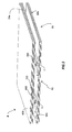
Figure 4 , it is shown acomponent 3 according to a second preferred embodiment of the invention. - Similarly, the
component 3 comprises the plurality of stackedlamination 21 comprising a pair ofadjacent lamination stacks corrugated layer 32 is interposed there between by means oflamination 221 deformed in such a way to obtainfirst recesses 222. Thecorrugated layer 32 definespassageways 7 for the coolant fluid. Thefirst recesses 222 are in this example in the form in longitudinal ducts, having in this embodiment a trapezoidal section. It will be appreciated that a rectangular section could be used instead. - In such embodiment, the
corrugated layer 32 comprises a second lamination, indicated in the figure withnumeral reference 321, disposed adjacent to the first lamination and deformed as well in such a way to define on its surface a plurality ofsecond recesses 322. Advantageously, recesses 222 and 322 have identical sections. First andsecond laminations second recesses second recess 322 is at least partially hosted into a correspondentfirst recess 222. - This configuration is particularly advantageous because it strengthens the mechanical stiffness and stability of the stacked lamination, especially in correspondence of the channels for the passage of cooling fluid.
- Moreover, the choice of trapezoidal section for the ducts formed on the lamination is particularly preferred as such section assures a minor mechanical stress on the material, which then guarantees a more reliable behaviour while in operation.
- With reference to
Figure 5 , it is shown a third preferred embodiment of the component according to the invention, denoted withnumeral 4. Similarly, thecomponent 4 comprises a pair ofadjacent stacks corrugated layer 42. Thecorrugated layer 42 comprises thefirst lamination 221 disposed on top of thestack 23b deformed as to definefirst recesses 222 having a form of longitudinal ducts (in this example having a substantially rectangular section). - In this third preferred embodiment, the corrugated layer comprises a
third lamination 421, in turn deformed in a way to define on its surface third recesses 422. In this example as well, first and third recesses have identical sections. However,first lamination 221 is opposite with respect tothird lamination 421 and disposed such that first andthird recesses - This configuration is particularly advantageous because it assures a homogeneous distribution of the pressures involved in the lamination stacks during operation.
- It will be appreciated that also various combinations of preferred embodiments may be carried out. For example, the third embodiment may have
first recesses 222 formed by a couple of laminations disposed as taught with reference to the second embodiment. - Making now reference to next
Figure 6 , it is shown acomponent 5 according to a forth embodiment of the present invention. - Similarly, the
component 5 comprises a pair ofadjacent stacks corrugated layer 52. This embodiment differs from the preceding ones in the fact that on afirst lamination 521 the recesses are in the form of a plurality of dimples, indicated in the figure with thereference number 522. - Advantageously, by means of the presence of
dimples passageways 7 are configured as a plurality of possible paths which the fluid can pass through. - It will be appreciated that preferred features of preceding preferred embodiments are applicable mutatis mutandis to the forth embodiment.
- More in particular, the
corrugated layer 52 may comprise asecond lamination 531 opposite to thefirst lamination 521, the two laminations having correspondent dimples disposed with opposite convexities such that each dimple of thefirst lamination 521 abuts on acorrespondent dimple 532, formed onsecond lamination 531. - Furthermore, each dimple on the stack may be formed by two laminations as described, mutatis mutandis, concerning second embodiment.
- Advantageously, as detailed in next
Figure 7 , each dimple may be hollow inside and comprise anopening 5221 configured to allow passage of the cooling fluid inside the dimple. This way, the surface for the heat exchange is greatly increased, thus greatly improving the process of heat removal. - With reference to the final
Figure 8 , it is shown a fifth last embodiment which is a combination of all the embodiments above described. In particular,Figure 8 illustrates a planar view of acorrugated layer 62 comprising a lamination 621 including a top portion having recesses in the form of a plurality of dimples, and lower portions characterized byrecesses 222 in the form of longitudinal ducts. - This combination of embodiments results to be extremely effective for the following reasons: the dimples are advantageous because, differently from longitudinal ducts, they don't provide preferred passageways for the flow of the cooling fluid but rather a plurality of possible channels where the fluid can be distributed. However, in the lower portion of the lamination the presence of
windings 20 cause a reduction of the available space for forming dimples, and therefore the formation longitudinal ducts completes the distribution of recesses on the lamination. This way it is assured a total coverage of the lamination for establishing the corrugated layer and thus a highly effective passage of cooling fluid for heat removal. It will also be appreciated that the fluid is not restricted to air only. By means of the use of components according to the present invention, water cooled heat exchangers integrated in the deformed laminations are also possible. The invention conceived in this manner is susceptible to numerous modifications and variants, all falling within the scope of the following claims. Moreover all details can be replaced by technically equivalent elements. - In practice the materials used and the dimensions can be chosen according to requirements and to the state of the art.
Claims (12)
- A component (2, 3, 4, 5, 6) for an electrical machine comprising a plurality of stacked laminations (21), the component (2, 3, 4, 5, 6) being characterized in that it comprises at least a corrugated layer (22, 32, 42, 52, 62) interposed between a pair of adjacent stacks (23a, 23b), such that said pair of adjacent stacks (23a, 23b) are spaced apart and such that a plurality of passageways (7) for a cooling fluid are formed there between.
- The component (2, 3, 4, 5, 6) according to the preceding claim, wherein the corrugated layer (22, 32, 42, 52, 62) comprises a first lamination (221, 521, 621) deformed in such a way to define on its surface a plurality of first recesses (222, 522).
- The component (2, 3, 4, 5, 6) according to claim 2, wherein the corrugated layer (32, 42, 52, 62) comprises a second lamination (321, 421, 531) being deformed in such a way to define on its surface a plurality of second recesses (322, 422, 532).
- The component (3) according to the preceding claim, wherein said first and second recesses (222, 322) have aligned concavities, said second lamination (321) being disposed adjacent to said first lamination (221) such that each second recess (322) is at least partially hosted into a correspondent first recess (222).
- The component (4, 5) according to any of claims 2 to 4, wherein said corrugated layer (42, 52) comprises a third lamination (421, 521) deformed in such a way to define on its surface a plurality of third recesses (422, 532), wherein said third and first recesses (422, 532; 222, 522) have opposite convexities, said third lamination (421, 521) being disposed opposite to said first lamination (221, 521) such that each third recess (422, 532) abuts on a correspondent first recess (222, 522).
- The component (2, 3, 4, 6) according to any of the preceding claims, wherein said recesses (222, 322, 422) comprise longitudinal ducts (222, 322, 422).
- The component (2, 3, 4, 6) according to the preceding claim, wherein said longitudinal ducts (222, 322, 422) have a substantially rectangular and/or trapezoidal section.
- The component (5, 6) according to any claims 6 or 7, wherein the recesses (522, 532) comprise dimples (522, 532).
- The component (5, 6) according to the preceding claim, where each dimple (522, 532) is hollow and comprises an opening (5221), the opening (5221) being configured to allow passage of the cooling inside said dimple (522, 532).
- The component (2, 3, 4, 5, 6) according to any of the preceding claims, wherein said corrugated layer (22, 32, 42, 52, 62) is obtained by a forming process.
- The component (2, 3, 4, 5, 6) according to the preceding claims, wherein the forming process is a hydroforming process.
- An electrical machine, characterized in that it comprises a component (2, 3, 4, 5, 6) according to any of the preceding claims.
Priority Applications (3)
| Application Number | Priority Date | Filing Date | Title |
|---|---|---|---|
| PT131940132T PT2876781T (en) | 2013-11-22 | 2013-11-22 | Electrical machine with improved cooling |
| ES13194013.2T ES2673200T3 (en) | 2013-11-22 | 2013-11-22 | Electric machine with improved cooling |
| EP13194013.2A EP2876781B1 (en) | 2013-11-22 | 2013-11-22 | Electrical machine with improved cooling |
Applications Claiming Priority (1)
| Application Number | Priority Date | Filing Date | Title |
|---|---|---|---|
| EP13194013.2A EP2876781B1 (en) | 2013-11-22 | 2013-11-22 | Electrical machine with improved cooling |
Publications (2)
| Publication Number | Publication Date |
|---|---|
| EP2876781A1 true EP2876781A1 (en) | 2015-05-27 |
| EP2876781B1 EP2876781B1 (en) | 2018-04-25 |
Family
ID=49626847
Family Applications (1)
| Application Number | Title | Priority Date | Filing Date |
|---|---|---|---|
| EP13194013.2A Not-in-force EP2876781B1 (en) | 2013-11-22 | 2013-11-22 | Electrical machine with improved cooling |
Country Status (3)
| Country | Link |
|---|---|
| EP (1) | EP2876781B1 (en) |
| ES (1) | ES2673200T3 (en) |
| PT (1) | PT2876781T (en) |
Cited By (1)
| Publication number | Priority date | Publication date | Assignee | Title |
|---|---|---|---|---|
| WO2019092315A1 (en) * | 2017-11-09 | 2019-05-16 | Lappeenrannan-Lahden Teknillinen Yliopisto Lut | A rotor of a synchronous reluctance machine and a method for manufacturing the same |
Citations (4)
| Publication number | Priority date | Publication date | Assignee | Title |
|---|---|---|---|---|
| DE103236C (en) * | ||||
| DE136878C (en) * | ||||
| JPS6430645U (en) * | 1987-08-17 | 1989-02-27 | ||
| EP2587639A2 (en) * | 2011-10-25 | 2013-05-01 | General Electric Company | Lamination stack for an electrical machine stator |
-
2013
- 2013-11-22 PT PT131940132T patent/PT2876781T/en unknown
- 2013-11-22 ES ES13194013.2T patent/ES2673200T3/en active Active
- 2013-11-22 EP EP13194013.2A patent/EP2876781B1/en not_active Not-in-force
Patent Citations (4)
| Publication number | Priority date | Publication date | Assignee | Title |
|---|---|---|---|---|
| DE103236C (en) * | ||||
| DE136878C (en) * | ||||
| JPS6430645U (en) * | 1987-08-17 | 1989-02-27 | ||
| EP2587639A2 (en) * | 2011-10-25 | 2013-05-01 | General Electric Company | Lamination stack for an electrical machine stator |
Cited By (1)
| Publication number | Priority date | Publication date | Assignee | Title |
|---|---|---|---|---|
| WO2019092315A1 (en) * | 2017-11-09 | 2019-05-16 | Lappeenrannan-Lahden Teknillinen Yliopisto Lut | A rotor of a synchronous reluctance machine and a method for manufacturing the same |
Also Published As
| Publication number | Publication date |
|---|---|
| EP2876781B1 (en) | 2018-04-25 |
| ES2673200T3 (en) | 2018-06-20 |
| PT2876781T (en) | 2018-06-11 |
Similar Documents
| Publication | Publication Date | Title |
|---|---|---|
| JP7078360B2 (en) | Rotor core | |
| US10784745B2 (en) | Stators for electrical machines | |
| EP2503672B1 (en) | Method of providing the channels used for cooling of a Motor stator | |
| US10243419B2 (en) | Arrangement for the stator cooling of an electric motor | |
| EP2458714B1 (en) | Wedge for a stator of a generator with preformed coil windings | |
| EP2658089B1 (en) | Stator cooling channel tolerant to localized blockage | |
| JP6169505B2 (en) | Manufacturing method of rotor laminated core | |
| US20230243339A1 (en) | Wind turbine with at least one dynamoelectric machine | |
| US2781465A (en) | Rotor for electric motor | |
| EP2787607A2 (en) | Electric machine rotor | |
| EP2244355B1 (en) | Dynamoelectric machine rotors having enhanced heat transfer and method therefor | |
| US8390156B2 (en) | Rotor for a multipolar synchronous electric machine with salient poles | |
| EP2876781B1 (en) | Electrical machine with improved cooling | |
| US9780631B2 (en) | Method for stamping coil sides of a stator winding | |
| JP2019110664A (en) | Cooling structure for stator | |
| US10014740B2 (en) | Chamber for conductors of electric machines | |
| WO2015086397A1 (en) | Winding for an electric machine | |
| CN115378176A (en) | Stator of an electric machine, method for producing such a stator and electric machine | |
| KR102080633B1 (en) | End-ring for induction mortor, Rotator having the same | |
| JP5900319B2 (en) | Induction motor | |
| EP3367539B1 (en) | Electrical machine laminations | |
| CN107086682A (en) | Motor rotor, motor and method for manufacturing such rotor | |
| CN112421818A (en) | Stator core | |
| JP6696698B2 (en) | Rotating electric machine stator | |
| KR20120079816A (en) | Apparatus for ventilating stator core |
Legal Events
| Date | Code | Title | Description |
|---|---|---|---|
| PUAI | Public reference made under article 153(3) epc to a published international application that has entered the european phase |
Free format text: ORIGINAL CODE: 0009012 |
|
| 17P | Request for examination filed |
Effective date: 20131122 |
|
| AK | Designated contracting states |
Kind code of ref document: A1 Designated state(s): AL AT BE BG CH CY CZ DE DK EE ES FI FR GB GR HR HU IE IS IT LI LT LU LV MC MK MT NL NO PL PT RO RS SE SI SK SM TR |
|
| AX | Request for extension of the european patent |
Extension state: BA ME |
|
| RAP1 | Party data changed (applicant data changed or rights of an application transferred) |
Owner name: GE RENEWABLE TECHNOLOGIES |
|
| 17Q | First examination report despatched |
Effective date: 20170517 |
|
| GRAP | Despatch of communication of intention to grant a patent |
Free format text: ORIGINAL CODE: EPIDOSNIGR1 |
|
| INTG | Intention to grant announced |
Effective date: 20180102 |
|
| GRAS | Grant fee paid |
Free format text: ORIGINAL CODE: EPIDOSNIGR3 |
|
| GRAA | (expected) grant |
Free format text: ORIGINAL CODE: 0009210 |
|
| STAA | Information on the status of an ep patent application or granted ep patent |
Free format text: STATUS: THE PATENT HAS BEEN GRANTED |
|
| AK | Designated contracting states |
Kind code of ref document: B1 Designated state(s): AL AT BE BG CH CY CZ DE DK EE ES FI FR GB GR HR HU IE IS IT LI LT LU LV MC MK MT NL NO PL PT RO RS SE SI SK SM TR |
|
| REG | Reference to a national code |
Ref country code: GB Ref legal event code: FG4D |
|
| REG | Reference to a national code |
Ref country code: CH Ref legal event code: EP |
|
| REG | Reference to a national code |
Ref country code: AT Ref legal event code: REF Ref document number: 993869 Country of ref document: AT Kind code of ref document: T Effective date: 20180515 |
|
| REG | Reference to a national code |
Ref country code: IE Ref legal event code: FG4D |
|
| REG | Reference to a national code |
Ref country code: DE Ref legal event code: R096 Ref document number: 602013036378 Country of ref document: DE |
|
| REG | Reference to a national code |
Ref country code: PT Ref legal event code: SC4A Ref document number: 2876781 Country of ref document: PT Date of ref document: 20180611 Kind code of ref document: T Free format text: AVAILABILITY OF NATIONAL TRANSLATION Effective date: 20180604 |
|
| REG | Reference to a national code |
Ref country code: ES Ref legal event code: FG2A Ref document number: 2673200 Country of ref document: ES Kind code of ref document: T3 Effective date: 20180620 |
|
| REG | Reference to a national code |
Ref country code: NL Ref legal event code: MP Effective date: 20180425 |
|
| REG | Reference to a national code |
Ref country code: LT Ref legal event code: MG4D |
|
| PG25 | Lapsed in a contracting state [announced via postgrant information from national office to epo] |
Ref country code: NL Free format text: LAPSE BECAUSE OF FAILURE TO SUBMIT A TRANSLATION OF THE DESCRIPTION OR TO PAY THE FEE WITHIN THE PRESCRIBED TIME-LIMIT Effective date: 20180425 |
|
| PG25 | Lapsed in a contracting state [announced via postgrant information from national office to epo] |
Ref country code: PL Free format text: LAPSE BECAUSE OF FAILURE TO SUBMIT A TRANSLATION OF THE DESCRIPTION OR TO PAY THE FEE WITHIN THE PRESCRIBED TIME-LIMIT Effective date: 20180425 Ref country code: LT Free format text: LAPSE BECAUSE OF FAILURE TO SUBMIT A TRANSLATION OF THE DESCRIPTION OR TO PAY THE FEE WITHIN THE PRESCRIBED TIME-LIMIT Effective date: 20180425 Ref country code: FI Free format text: LAPSE BECAUSE OF FAILURE TO SUBMIT A TRANSLATION OF THE DESCRIPTION OR TO PAY THE FEE WITHIN THE PRESCRIBED TIME-LIMIT Effective date: 20180425 Ref country code: BG Free format text: LAPSE BECAUSE OF FAILURE TO SUBMIT A TRANSLATION OF THE DESCRIPTION OR TO PAY THE FEE WITHIN THE PRESCRIBED TIME-LIMIT Effective date: 20180725 Ref country code: NO Free format text: LAPSE BECAUSE OF FAILURE TO SUBMIT A TRANSLATION OF THE DESCRIPTION OR TO PAY THE FEE WITHIN THE PRESCRIBED TIME-LIMIT Effective date: 20180725 Ref country code: SE Free format text: LAPSE BECAUSE OF FAILURE TO SUBMIT A TRANSLATION OF THE DESCRIPTION OR TO PAY THE FEE WITHIN THE PRESCRIBED TIME-LIMIT Effective date: 20180425 |
|
| PG25 | Lapsed in a contracting state [announced via postgrant information from national office to epo] |
Ref country code: GR Free format text: LAPSE BECAUSE OF FAILURE TO SUBMIT A TRANSLATION OF THE DESCRIPTION OR TO PAY THE FEE WITHIN THE PRESCRIBED TIME-LIMIT Effective date: 20180726 Ref country code: RS Free format text: LAPSE BECAUSE OF FAILURE TO SUBMIT A TRANSLATION OF THE DESCRIPTION OR TO PAY THE FEE WITHIN THE PRESCRIBED TIME-LIMIT Effective date: 20180425 Ref country code: LV Free format text: LAPSE BECAUSE OF FAILURE TO SUBMIT A TRANSLATION OF THE DESCRIPTION OR TO PAY THE FEE WITHIN THE PRESCRIBED TIME-LIMIT Effective date: 20180425 Ref country code: HR Free format text: LAPSE BECAUSE OF FAILURE TO SUBMIT A TRANSLATION OF THE DESCRIPTION OR TO PAY THE FEE WITHIN THE PRESCRIBED TIME-LIMIT Effective date: 20180425 |
|
| REG | Reference to a national code |
Ref country code: DE Ref legal event code: R097 Ref document number: 602013036378 Country of ref document: DE |
|
| PG25 | Lapsed in a contracting state [announced via postgrant information from national office to epo] |
Ref country code: CZ Free format text: LAPSE BECAUSE OF FAILURE TO SUBMIT A TRANSLATION OF THE DESCRIPTION OR TO PAY THE FEE WITHIN THE PRESCRIBED TIME-LIMIT Effective date: 20180425 Ref country code: SK Free format text: LAPSE BECAUSE OF FAILURE TO SUBMIT A TRANSLATION OF THE DESCRIPTION OR TO PAY THE FEE WITHIN THE PRESCRIBED TIME-LIMIT Effective date: 20180425 Ref country code: RO Free format text: LAPSE BECAUSE OF FAILURE TO SUBMIT A TRANSLATION OF THE DESCRIPTION OR TO PAY THE FEE WITHIN THE PRESCRIBED TIME-LIMIT Effective date: 20180425 Ref country code: DK Free format text: LAPSE BECAUSE OF FAILURE TO SUBMIT A TRANSLATION OF THE DESCRIPTION OR TO PAY THE FEE WITHIN THE PRESCRIBED TIME-LIMIT Effective date: 20180425 Ref country code: EE Free format text: LAPSE BECAUSE OF FAILURE TO SUBMIT A TRANSLATION OF THE DESCRIPTION OR TO PAY THE FEE WITHIN THE PRESCRIBED TIME-LIMIT Effective date: 20180425 |
|
| PGFP | Annual fee paid to national office [announced via postgrant information from national office to epo] |
Ref country code: PT Payment date: 20181102 Year of fee payment: 6 Ref country code: AT Payment date: 20181024 Year of fee payment: 6 Ref country code: DE Payment date: 20181023 Year of fee payment: 6 |
|
| PG25 | Lapsed in a contracting state [announced via postgrant information from national office to epo] |
Ref country code: SM Free format text: LAPSE BECAUSE OF FAILURE TO SUBMIT A TRANSLATION OF THE DESCRIPTION OR TO PAY THE FEE WITHIN THE PRESCRIBED TIME-LIMIT Effective date: 20180425 Ref country code: IT Free format text: LAPSE BECAUSE OF FAILURE TO SUBMIT A TRANSLATION OF THE DESCRIPTION OR TO PAY THE FEE WITHIN THE PRESCRIBED TIME-LIMIT Effective date: 20180425 |
|
| PGFP | Annual fee paid to national office [announced via postgrant information from national office to epo] |
Ref country code: ES Payment date: 20181203 Year of fee payment: 6 Ref country code: CH Payment date: 20181030 Year of fee payment: 6 |
|
| PLBE | No opposition filed within time limit |
Free format text: ORIGINAL CODE: 0009261 |
|
| STAA | Information on the status of an ep patent application or granted ep patent |
Free format text: STATUS: NO OPPOSITION FILED WITHIN TIME LIMIT |
|
| 26N | No opposition filed |
Effective date: 20190128 |
|
| PG25 | Lapsed in a contracting state [announced via postgrant information from national office to epo] |
Ref country code: SI Free format text: LAPSE BECAUSE OF FAILURE TO SUBMIT A TRANSLATION OF THE DESCRIPTION OR TO PAY THE FEE WITHIN THE PRESCRIBED TIME-LIMIT Effective date: 20180425 |
|
| GBPC | Gb: european patent ceased through non-payment of renewal fee |
Effective date: 20181122 |
|
| PG25 | Lapsed in a contracting state [announced via postgrant information from national office to epo] |
Ref country code: LU Free format text: LAPSE BECAUSE OF NON-PAYMENT OF DUE FEES Effective date: 20181122 Ref country code: MC Free format text: LAPSE BECAUSE OF FAILURE TO SUBMIT A TRANSLATION OF THE DESCRIPTION OR TO PAY THE FEE WITHIN THE PRESCRIBED TIME-LIMIT Effective date: 20180425 |
|
| REG | Reference to a national code |
Ref country code: BE Ref legal event code: MM Effective date: 20181130 |
|
| REG | Reference to a national code |
Ref country code: IE Ref legal event code: MM4A |
|
| PG25 | Lapsed in a contracting state [announced via postgrant information from national office to epo] |
Ref country code: IE Free format text: LAPSE BECAUSE OF NON-PAYMENT OF DUE FEES Effective date: 20181122 Ref country code: FR Free format text: LAPSE BECAUSE OF NON-PAYMENT OF DUE FEES Effective date: 20181130 |
|
| PG25 | Lapsed in a contracting state [announced via postgrant information from national office to epo] |
Ref country code: BE Free format text: LAPSE BECAUSE OF NON-PAYMENT OF DUE FEES Effective date: 20181130 Ref country code: AL Free format text: LAPSE BECAUSE OF FAILURE TO SUBMIT A TRANSLATION OF THE DESCRIPTION OR TO PAY THE FEE WITHIN THE PRESCRIBED TIME-LIMIT Effective date: 20180425 |
|
| REG | Reference to a national code |
Ref country code: AT Ref legal event code: UEP Ref document number: 993869 Country of ref document: AT Kind code of ref document: T Effective date: 20180425 |
|
| PG25 | Lapsed in a contracting state [announced via postgrant information from national office to epo] |
Ref country code: GB Free format text: LAPSE BECAUSE OF NON-PAYMENT OF DUE FEES Effective date: 20181122 |
|
| PG25 | Lapsed in a contracting state [announced via postgrant information from national office to epo] |
Ref country code: MT Free format text: LAPSE BECAUSE OF NON-PAYMENT OF DUE FEES Effective date: 20181122 |
|
| PG25 | Lapsed in a contracting state [announced via postgrant information from national office to epo] |
Ref country code: TR Free format text: LAPSE BECAUSE OF FAILURE TO SUBMIT A TRANSLATION OF THE DESCRIPTION OR TO PAY THE FEE WITHIN THE PRESCRIBED TIME-LIMIT Effective date: 20180425 |
|
| REG | Reference to a national code |
Ref country code: DE Ref legal event code: R119 Ref document number: 602013036378 Country of ref document: DE |
|
| PG25 | Lapsed in a contracting state [announced via postgrant information from national office to epo] |
Ref country code: HU Free format text: LAPSE BECAUSE OF FAILURE TO SUBMIT A TRANSLATION OF THE DESCRIPTION OR TO PAY THE FEE WITHIN THE PRESCRIBED TIME-LIMIT; INVALID AB INITIO Effective date: 20131122 Ref country code: MK Free format text: LAPSE BECAUSE OF NON-PAYMENT OF DUE FEES Effective date: 20180425 Ref country code: CY Free format text: LAPSE BECAUSE OF FAILURE TO SUBMIT A TRANSLATION OF THE DESCRIPTION OR TO PAY THE FEE WITHIN THE PRESCRIBED TIME-LIMIT Effective date: 20180425 |
|
| REG | Reference to a national code |
Ref country code: CH Ref legal event code: PL |
|
| PG25 | Lapsed in a contracting state [announced via postgrant information from national office to epo] |
Ref country code: LI Free format text: LAPSE BECAUSE OF NON-PAYMENT OF DUE FEES Effective date: 20191130 Ref country code: CH Free format text: LAPSE BECAUSE OF NON-PAYMENT OF DUE FEES Effective date: 20191130 Ref country code: PT Free format text: LAPSE BECAUSE OF NON-PAYMENT OF DUE FEES Effective date: 20200625 Ref country code: IS Free format text: LAPSE BECAUSE OF FAILURE TO SUBMIT A TRANSLATION OF THE DESCRIPTION OR TO PAY THE FEE WITHIN THE PRESCRIBED TIME-LIMIT Effective date: 20180825 |
|
| REG | Reference to a national code |
Ref country code: AT Ref legal event code: MM01 Ref document number: 993869 Country of ref document: AT Kind code of ref document: T Effective date: 20191122 |
|
| PG25 | Lapsed in a contracting state [announced via postgrant information from national office to epo] |
Ref country code: DE Free format text: LAPSE BECAUSE OF NON-PAYMENT OF DUE FEES Effective date: 20200603 |
|
| PG25 | Lapsed in a contracting state [announced via postgrant information from national office to epo] |
Ref country code: AT Free format text: LAPSE BECAUSE OF NON-PAYMENT OF DUE FEES Effective date: 20191122 |
|
| REG | Reference to a national code |
Ref country code: ES Ref legal event code: FD2A Effective date: 20210531 |
|
| PG25 | Lapsed in a contracting state [announced via postgrant information from national office to epo] |
Ref country code: ES Free format text: LAPSE BECAUSE OF NON-PAYMENT OF DUE FEES Effective date: 20191123 |