EP2876760A1 - Arm power supply device - Google Patents
Arm power supply device Download PDFInfo
- Publication number
- EP2876760A1 EP2876760A1 EP13819277.8A EP13819277A EP2876760A1 EP 2876760 A1 EP2876760 A1 EP 2876760A1 EP 13819277 A EP13819277 A EP 13819277A EP 2876760 A1 EP2876760 A1 EP 2876760A1
- Authority
- EP
- European Patent Office
- Prior art keywords
- arm
- wire harness
- power supply
- wall
- supply device
- Prior art date
- Legal status (The legal status is an assumption and is not a legal conclusion. Google has not performed a legal analysis and makes no representation as to the accuracy of the status listed.)
- Granted
Links
- 230000002093 peripheral effect Effects 0.000 claims description 17
- 238000005452 bending Methods 0.000 abstract description 24
- 230000001012 protector Effects 0.000 description 13
- 238000003780 insertion Methods 0.000 description 7
- 230000037431 insertion Effects 0.000 description 7
- 238000005192 partition Methods 0.000 description 6
- 229920003002 synthetic resin Polymers 0.000 description 6
- 239000000057 synthetic resin Substances 0.000 description 6
- 230000002411 adverse Effects 0.000 description 5
- 210000000078 claw Anatomy 0.000 description 3
- 239000002184 metal Substances 0.000 description 3
- 230000001105 regulatory effect Effects 0.000 description 3
- 238000006467 substitution reaction Methods 0.000 description 3
- 238000004804 winding Methods 0.000 description 3
- 230000001154 acute effect Effects 0.000 description 1
- 238000013459 approach Methods 0.000 description 1
- 238000010586 diagram Methods 0.000 description 1
- 230000000694 effects Effects 0.000 description 1
- 238000000034 method Methods 0.000 description 1
- 238000007665 sagging Methods 0.000 description 1
Images
Classifications
-
- B—PERFORMING OPERATIONS; TRANSPORTING
- B60—VEHICLES IN GENERAL
- B60R—VEHICLES, VEHICLE FITTINGS, OR VEHICLE PARTS, NOT OTHERWISE PROVIDED FOR
- B60R16/00—Electric or fluid circuits specially adapted for vehicles and not otherwise provided for; Arrangement of elements of electric or fluid circuits specially adapted for vehicles and not otherwise provided for
- B60R16/02—Electric or fluid circuits specially adapted for vehicles and not otherwise provided for; Arrangement of elements of electric or fluid circuits specially adapted for vehicles and not otherwise provided for electric constitutive elements
- B60R16/0207—Wire harnesses
- B60R16/0215—Protecting, fastening and routing means therefor
-
- B—PERFORMING OPERATIONS; TRANSPORTING
- B60—VEHICLES IN GENERAL
- B60R—VEHICLES, VEHICLE FITTINGS, OR VEHICLE PARTS, NOT OTHERWISE PROVIDED FOR
- B60R16/00—Electric or fluid circuits specially adapted for vehicles and not otherwise provided for; Arrangement of elements of electric or fluid circuits specially adapted for vehicles and not otherwise provided for
- B60R16/02—Electric or fluid circuits specially adapted for vehicles and not otherwise provided for; Arrangement of elements of electric or fluid circuits specially adapted for vehicles and not otherwise provided for electric constitutive elements
- B60R16/023—Electric or fluid circuits specially adapted for vehicles and not otherwise provided for; Arrangement of elements of electric or fluid circuits specially adapted for vehicles and not otherwise provided for electric constitutive elements for transmission of signals between vehicle parts or subsystems
- B60R16/027—Electric or fluid circuits specially adapted for vehicles and not otherwise provided for; Arrangement of elements of electric or fluid circuits specially adapted for vehicles and not otherwise provided for electric constitutive elements for transmission of signals between vehicle parts or subsystems between relatively movable parts of the vehicle, e.g. between steering wheel and column
-
- F—MECHANICAL ENGINEERING; LIGHTING; HEATING; WEAPONS; BLASTING
- F16—ENGINEERING ELEMENTS AND UNITS; GENERAL MEASURES FOR PRODUCING AND MAINTAINING EFFECTIVE FUNCTIONING OF MACHINES OR INSTALLATIONS; THERMAL INSULATION IN GENERAL
- F16L—PIPES; JOINTS OR FITTINGS FOR PIPES; SUPPORTS FOR PIPES, CABLES OR PROTECTIVE TUBING; MEANS FOR THERMAL INSULATION IN GENERAL
- F16L3/00—Supports for pipes, cables or protective tubing, e.g. hangers, holders, clamps, cleats, clips, brackets
- F16L3/01—Supports for pipes, cables or protective tubing, e.g. hangers, holders, clamps, cleats, clips, brackets for supporting or guiding the pipes, cables or protective tubing, between relatively movable points, e.g. movable channels
- F16L3/015—Supports for pipes, cables or protective tubing, e.g. hangers, holders, clamps, cleats, clips, brackets for supporting or guiding the pipes, cables or protective tubing, between relatively movable points, e.g. movable channels using articulated- or supple-guiding elements
-
- H—ELECTRICITY
- H02—GENERATION; CONVERSION OR DISTRIBUTION OF ELECTRIC POWER
- H02G—INSTALLATION OF ELECTRIC CABLES OR LINES, OR OF COMBINED OPTICAL AND ELECTRIC CABLES OR LINES
- H02G11/00—Arrangements of electric cables or lines between relatively-movable parts
Definitions
- the present invention for example, relates to an arm power supply device which is mounted on a sliding door in an automobile and wires a wire harness to a vehicle body by an arm supported to a base member to be freely rotated.
- a wire harness is urged upward by a metal flat spring while wiring the wire harness in a bent shape in the protector vertically disposed in the sliding door using a synthetic-resin protector formed by a protector base and a protector cover, the wire harness is wired up to a harness supporter on a side near a vehicle body through a lower opening of the protector, and sagging (extra length) of the wire harness at the time when the sliding door is a half-open state is absorbed.
- Patent Literature 2 discloses that a link arm is rotatably and axially supported on a plate protector base vertically disposed in the sliding door, the link arm is urged upward by a torsion coil spring (spring member), a harness holder is rotatably and axially supported to the link arm, the wire harness is wired along the protector base to the harness holder and fixed thereto and wired from the harness holder to a side near the vehicle body, and a protector cover may be not used.
- a torsion coil spring spring member
- the protector and the protector base (base member) including the protector cover (a cover member) is easily increased in size, and mounting spaces for other components become reduced when the power supply device is disposed in the sliding door of an automobile.
- the invention has been made in view of the above circumstances, and an object is to provide an arm power supply device which can prevent the bending of the power supply arm in the width direction, resolve the rattling of the wire harness and the instability of the trajectory, improve the bending resistance of the wire harness, minimize the structure of the power supply device while eliminating the cover member, and prevent the spring member from being fallen out of the arm.
- an arm power supply device in which a first arm is rotatably and axially supported to a base member having one harness fixing portion, a second arm having the other harness fixing portion is rotatably and axially supported on a rotation tip side of the first arm, the first arm includes an enclosure portion forming a slit through which a wire harness is inserted, and the wire harness passes from the base member to the slit and is wired over the second arm.
- the rigidity of the first arm is increased by the enclosure portion surrounding the slit, and the bending of the first arm in the width direction is prevented.
- the wire harness is inserted in the slit of the first arm and freely moves in the longitudinal direction of the slit, but the movement of the wire harness in the width direction of the slit is regulated. Therefore, the rattling of the wire harness in the width direction of the slit (the width direction of the first arm) is suppressed, and the trajectory in the longitudinal direction of the slit (the longitudinal direction of the first arm) becomes stable.
- the wire harness is wired in an approximate S shape from the base member to the second arm through the slit of the first arm.
- the arm power supply device in the arm power supply device of claim 1, is characterized in that the enclosure portion includes an inclined wall on a rotational base end side of the first arm such that the wire harness derived in a bent shape from the second arm is guided to be in contact with an inner surface.
- the arm power supply device in the arm power supply device of claim 1 or 2, is characterized in that a peripheral end of the base member is disposed in the vicinity of an end portion of the enclosure portion on a rotational base end side of the first arm in a rotation range of the first arm.
- the portion on the rotational base end side of the first arm is reliably supported by the base member to be freely rotated, and the base member is miniaturized. Therefore, while securing the smooth rotation of the first arm, a mounting portion in which the base member is mounted on the sliding door of the vehicle is saved.
- the arm power supply device in the arm power supply device of any one of claims 1 to 3, is characterized in that a torsion coil spring to urge the first arm in a rotation direction is contained on a rotational base end side of the first arm, and an engagement portion to engage one end portion of the torsion coil spring is provided on the rotational base end side.
- the engagement portion is desirable to be a flexible engagement arm.
- the rigidity of the first arm in the width direction is increased by the enclosure portion of the first arm, so that it is possible to prevent deformation such as an adverse bending of the first arm when the wire harness is forcibly pulled. Further, since the wire harness is inserted into the slit of the first arm, the rattling of the wire harness is prevented, the trajectory of the wire harness becomes stable. For example, it is possible to smoothly operate the wire harness without deformation such as an adverse bending when the sliding door of the automobile is opened or closed. Therefore, the bending resistance of the wire harness can be improved.
- the bended wire harness derived from the second arm is in contact with the inner surface of the inclined wall of the enclosure portion of the first arm, so that the bent shape of the wire harness is maintained, and the adverse folding and the like are prevented. Therefore, the bending resistance of the wire harness can be improved.
- the cover member is eliminated from the power supply device and the base member is miniaturized while keeping a smooth rotation of the first arm, so that the power supply device can be miniaturized and lightened. Further, for example, a mounting space of the base member in the sliding door of the vehicle can be saved.
- Figs. 1 and 2 illustrate an embodiment of an arm power supply device according to the invention.
- the arm power supply device 1 is configured to include a small synthetic resin base member 2 which is vertically fixed to a metal door inner panel 10 ( Fig. 2 ) of a sliding door of an automobile, a long synthetic resin first arm 3 which is rotatably and axially supported to the base member 2 in the upward and downward direction and has an enclosure portion 5 in the center forming a slit 4 for inserting a wire harness, and a short synthetic resin second arm 8 which is rotatably and axially supported to a rotation tip 6 of the first arm 3 in the upward and downward direction and has a harness fixing portion 58 on a rotation tip side of its own.
- the arm power supply device 1 in this example is used for the sliding door of the left side of a vehicle
- a near side in Fig. 1 indicates a vehicle outside (a side near the door panel 10 of Fig. 2 ) and a deep side indicates a vehicle inside (a side near a door trim 11 of Fig. 2 ).
- the left side (a side near the first arm 3) of Fig. 1 indicates the front side of the vehicle and the right side (a side near the base member 2) indicates the back side of the vehicle.
- Figs. 1 and 2 illustrate a state in which the first arm 3 is urged upward by an urging force of the spring member 9 ( Fig. 7 ) on the rotational base end side 7 at the time when the sliding door is half open and a harness extra length is absorbed.
- the base member 2 is formed to have a longitudinal length almost the same degree as the entire length of the first arm 3 and a vertical length almost twice times the width of the first arm 3, and is miniaturized in the longitudinal and vertical directions.
- the thickness of the base member 2 is almost one and half times the thickness of the first arm 3, and is compacted in the width direction.
- Fig. 3 illustrates an embodiment of the base member 2.
- the base member 2 includes a base plate 12 which is substantially perpendicular in the vertical direction, an upper wall 13 which is inclined downward along the upper end of the base plate 12, a partition wall 15 which is disposed below the upper wall 13 with a harness guide (insertion) path 14 formed therebetween, a bottomed cylindrical fixing portion 16 which is provided on the lower end side of a bent rear portion 15a of the partition wall 15, a bottomed cylindrical fixing portion 17 which is provided on the upper end side of the front part of the partition wall 15 and also serves as a stopper to regulate an upward rotation angle (the clockwise direction) of the first arm 3 ( Fig.
- an inclined wall 18 which is inclined upward from the fixing portion 16 on the lower side and serves as a stopper to regulate a downwardly rotation angle (the counterclockwise direction) of the first arm 3, a fixing clip 19 ( Figs. 1 and 2 ) which is provided between the inclined wall 18 and the rear semi-bent portion 15a of the partition wall 15, a shaft 20 ( Fig. 3 ) which protrudes from the base plate 12 and supports the first arm, and a guide wall 21 which is formed at a low height in a substantially annular shape.
- the fixing portions 16 and 17 provided in the front and rear parts of the base member 2 respectively include bolt insertion holes 16b and 17b in bottom walls 16a and 17a. As illustrated in Fig. 2 , the bottom walls 16a and 17a of the fixing portions 16 and 17 are in contact with the metal door inner panel 10 to be fastened and fixed by bolts and nuts (not illustrated), and the locking clip 19 passes through a hole (not illustrated) formed in the door inner panel 10 for engagement.
- the fixing portions 16 and 17 each protrude from the base plate 12 of the base member 2 toward the door inner panel 10, the rotational base end portion 7 in the annular shape (a circular shape in front view) of the first arm 3 is positioned in a nearly fan-shaped concave space (use symbol 12 in substitution) between the fixing portions 16 and 17 provided in the front and rear (upper and lower) parts along the base plate 12, and an outer surface 22 of the first arm 3 slightly recedes to the base plate 12 compared to the bottom walls 16a and 17a of the fixing portions 6 and 7.
- the shaft 20 of the base member 2 includes a slit 20a ( Fig. 3 ) which is flexible inward in a radial direction, and has a locking claw 20b at the tip.
- the locking claw 20b ( Fig. 3 ) is engaged with the peripheral of the hole portion 23.
- a shaft 24 provided in the second arm 8 ( Fig. 1 ) is also configured to be engaged with a hole portion 25 ( Fig. 4 ) on the tip side of the first arm 3.
- a cylindrical wall portion 26 is provided in the surrounding area of the shaft 2 0 ( Fig. 3 ) of the base member 2, and a guide peripheral wall 21 is provided on the outside thereof.
- Symbol 27 denoted in Fig. 3 indicates a portion on which the locking clip 19 is mounted.
- the harness guide path 14 ( Fig. 3 ) of the base member 2 is vertically branched in a short distance on the rear end side (upper and lower branch passages are denoted by symbols 14a and 14b), and as illustrated in Fig. 1 , a main body (denoted by symbol 28) of a wire harness 28 passes through the lower side slightly lower than the lower end of the base plate 12 of the base member 2 along the lower branch passage 14b from the harness guide path 14, and then wired along the second arm 8 through the slit 4 in the enclosure portion 5 of the first arm 3 while being bent in an approximate S shape.
- One wire harness 28 is wired from the harness guide path 14 toward the sliding door side, and the other wire harness 28 is wired from the second arm 8 up to a harness supporter (not illustrated) on a vehicle body side.
- the wire harness 28 is fixed by a binding band (not illustrated) in the branch passage (the harness fixing portion) 14b on the lower side of the harness guide path 14 (a band insertion hole is denoted by symbol 29), and is interposed and fixed by a cover portion (the harness fixing portion) 58 on a rotation tip side of the second arm 8.
- the first arm 3 includes wall surfaces 22a and 30a ( Fig. 2 ) which are flat and straight on front and back sides (outside and inside), an annular portion (the annular shape wall) 31 ( Fig. 1 ) which is formed straight in the surrounding area of a circular wall portion 48 on the same plane as the wall surface 22a on the front side and has a depth equal to the interval of the wall surfaces 22a and 30a on the front side, a portion on the rotation tip side 6 which is formed continuously on the same plane as the wall surface 22a on the front side and connected to the wall surface 30a on the back side through a step portion 32 ( Fig.
- the slit 4 which is formed between the annular portion 31 on the rotational base end side and the portion on the rotation tip side 6 to insert the harness between plate wall portions 22 and 30 forming the wall surfaces 22a and 30a on the front and back sides, plate inclined wall portions (the inclined walls) 35 and 36 which are formed in the front and rear parts and intersect with the plate wall portions 22 and 30 on the front and back sides to form the inner surfaces in the front and rear parts of the slit 4, and the enclosure portion 5 which is surrounded on all sides by the wall portions 22, 30, 35, and 36.
- the slit 4 surrounded on all sides by the plate wall portions 22, 30, 35, and 36, that is, the enclosure portion 5 is formed in an approximate chevron shape (the taper shape) in vertically cross-sectional view such that an opening 4b on the lower end side is widened and an opening 4a on the upper end side is narrowed when the first arm 3 is substantially horizontally positioned.
- the slit 4 is formed by being surrounded by the plate wall portions 22 and 30 on the front and back sides and the plate inclined walls 35 and 36 for guiding the harness in the front and rear parts, which constitutes the enclosure portion 5.
- the inclined wall 35 on the front side (near the rotation tip) of the enclosure portion 5 includes a straight inner wall surface (use symbol 35 in substitution) and a small-radius bent surface 35a on the upper and lower ends (on the sides near the upper and lower openings 4a and 4b) of the inner wall surface 35.
- An outer wall surface 35b of the inclined wall 35 on the front side is connected to the step wall 32 ( Fig. 5 ) on the rotation tip side through a rib 37.
- the inclined wall 36 on the rear side is configured by an arc-shape wall portion 36a which is a part of the lower half portion of the circular annular wall 31 on the rotational base end side and a straight wall portion (use symbol 36 in substitution) which is straightly extended from the arc-shape wall portion 36a in a tangential direction, and the upper end (a portion on the opening 4a side on the upper side) of the straight wall portion 36 has a small-radius bent surface (end portion) 36b.
- a concave portion 47 On the narrow opening 4a side on the upper side of the slit 4, is formed a concave portion 47 having almost the triangle shape between the straight wall portion 36 and an annular wall 31 on the base end side.
- a longitudinal length of the opening 4a on the upper side of the slit 4 is slightly shorter than a total sum of lengths of the inclined walls 35 and 36 in the front and rear parts, and the longitudinal length of the opening 4b on the lower side of the slit 4 is longer than a total sum of lengths of the inclined walls 35 and 36 in the front and rear parts.
- a cylindrical bearing member 38 is integrally provided in the step portion 32 on the rear side of the rotation tip 6 of the first arm 3 to support the shaft 24 of the second arm 8 ( Fig. 1 ) to be freely rotated.
- a notch portion 40 is provided in the latter half of the annular wall 31 on the rotational base end side of the first arm 3 such that one end portion 9a of the spring member (the torsion coil spring) 9 of Fig. 7 is made to protrude to be engaged with a concave portion 39 of the partition wall 15 of the base member 2 of Fig. 1 .
- the wire harness 28 since the wire harness 28 is inserted (passing through) into the slit 4 of the first arm 3, the wire harness 28 freely moves in the longitudinal direction of the first arm 3 when the first arm 3 rotates according to opening and closing of the sliding door, and the movement of the wire harness 28 to the width direction of the first arm 3 is prevented so that the trajectory of the wire harness 28 becomes stable. Therefore, small-radius bending and folding of the wire harness 28 is prevented, so that the bending resistance is improved.
- the wall portion 22 on the front (outer) side of the enclosure portion 5 of the first arm 3 serves as a cover of the power supply device in the related art, the movement of the wire harness 28 to the outside of the vehicle is regulated (prevented) and the interference between a member (the door inner panel 10 and the like) on the outside of the vehicle and the wire harness 28. Therefore, the cover used in the related art becomes unnecessary, and the power supply device 1 is simplified, miniaturized, lowered in cost, and reduced in weight.
- the enclosure portion 5 of the first arm 3 includes the plate wall portions 22 and 30 parallel to each other on right and left sides and the inclined walls 35 and 36 inclined in an approximate chevron shape (the taper shape) facing each other in the front and rear parts, and the rigidity of the first arm 3 is increased by the respective wall portions 22, 30, 35, and 36 which constitute the enclosure portion 5 and are integrally formed in a surrounding frame shape, and the first arm 3 is reduced in weight by the surrounding wall portions 22, 30, 35, and 36 which are made relatively thin. It is a matter of course that the first arm 3 is reduced in weight by forming the slit 4 surrounded by the enclosure portion 5.
- the front end portion (the peripheral end) 12a of the vertical base plate 12 of the base member 2 forms the end portion in the bent shape with the shaft 20 of the first arm 3 as almost the center, and approaches the inclined wall 36 on the rear side of the peripheral end portion 12a in the bent shape of the first arm 3 to be positioned (specifically, slightly protrudes forward from the inclined wall 36 on the rear side) in the vicinity of the upper end (end portion) 36b of the inclined wall 36, and thus the base member 2 is shortened in the longitudinal direction compared to the related art.
- the bent endportion 12a slightly protrudes forward from the inclined wall 36 on the rear side, so that the rotational base end portion 7 is reliably supported (received) to the first arm 3 by the base plate 12 and the smooth rotation of the first arm 3 is reliably secured.
- an almost-horizontal lower end portion (the peripheral end) 12b formed continuously on the bent end portion (the peripheral end) 12a on the front side of the base plate 12 of the base member 2 is positioned in the vicinity of the lower end (the end portion 36b on the narrow opening 4a of the slit 4) of the inclined wall 36 on the rotational base end side of the enclosure portion 5 of the first arm 3, so that the base member 2 is shortened even in the upward and downward direction compared to the related art.
- the peripheral ends 12a and 12b of the base member 2 are disposed in the vicinity of the end portion 36 of the enclosure portion 5 on the rotational base end side of the first arm 3.
- the first arm 3 in Fig. 4 is located at a rotational position substantially at the same level or slightly lower than the time when the sliding door of Fig. 1 is the half-open state, and the wire harness 28 is in contact along the inclined wall 36 on the rear side (the rotational base end side) of the enclosure portion 5 of the first arm 3, so that the trajectory of the wire harness 28 is regulated and a bent shape in an approximate S shape of the wire harness 28 of Fig. 1 is maintained. Therefore, the small-radius bending such as the bending of the wire harness 28, and the bending tendency of the wire harness 28 according to the small-radius bending are reliably prevented.
- the inner surface of the inclined wall 36 on the rear side serves as a contact surface for guiding the wire harness 28.
- the wire harness 28 passes through the slit 4 in the enclosure portion 5 of the first arm 3 from the downwardly bent portion 28a (the harness insertion portion is denoted by symbol 28b) and bent upward in the approximate semicircular shape (the upwardly bent portion is denoted by symbol 28c), and is fixed by the binding band which is the harness fixing portion on the rotation tip side of the second arm 8 (the band insertion hole is denoted by symbol 45) and the cover portion 58 while being wired in the bent shape along the second arm 8 (the harness wired portion is denoted by symbol 28d).
- the second arm 8 is formed to have about the half or slightly shorter than the length of the first arm 3, includes a bent gutter portion 41 on the front side (the upper side), a base wall 42 which is approximately straight on the rear side (the lower side), the shaft 24 which protrudes to the base end side of the base wall 42, and the cover portion 58 having a semicircular shape in cross-sectional view which is provided to be opened and closed by a thin hinge 41b in a portion 41a ( Fig. 2 ) having a semicircular shape in cross-sectional view on the rotation tip side of the gutter portion 41.
- the cover portion 58 is engaged with the base wall 42 in a state of being closed by an engagement means (a claw portion and a hole portion) 43.
- the gutter portion 41 is offset from the shaft 24 to the front side (the upper side).
- the wire harness 28 wraps the end portion of the corrugate tube 60 through a tape winding portion (not illustrated) on an outer peripheral side of the end portion of the mesh tube 59 to be interposed and fixed into the cover portion 58 in a state where a plurality of electric lines are covered with a small-radius synthetic resin mesh tube (protection tube) 59 having a good bending property in a range from the base member 2 to the cover portion 58 of the second arm 8 and the plurality of electric lines are covered with a large-radius synthetic resin corrugate tube (protection tube) 60 also in a range from the cover portion 58 to the harness supporter on a side near the vehicle body through a connection portion between the sliding door and the vehicle body.
- a tape winding portion not illustrated
- a sharp projection may be provided to pass and fix the end portion of the corrugate tube 60 and the tape winding portion of the end portion of the mesh tube 59.
- the base wall 42 of the second arm 8 is positioned in the step portion 32 on the rotation tip side of the first arm 3
- a circular harness insertion space 44 in the cover portion 58 is positioned collinearly (on a vertical plane) to the slit 4 for inserting the harness of the first arm 3
- the wire harness 28 is bent in the upward and downward direction without deviation in position in the right and left direction from the cover portion 58 to the slit 4.
- the first arm 3 is urged upward by an urging force of the spring member 9, the bent upper wall surface 46 on the front side formed continuously on the annular wall 31 on the base end side of the first arm 3 is in contact with the bent lower surface of the cylindrical fixing portion 17 on the front side of the base member 2, the upward rotation of the first arm 3 is prevented, the wire harness 28 is lifted up together with the first arm 3, and the bent harness portion 28a is prevented from being hanging down along the lower end 12b of the base member 2.
- the first arm 3 is slightly inclined upward from the horizontal level, the second arm 8 is inclined downward, and an angle ⁇ formed between both arms 3 and 8 becomes an obtuse angle of 90° or larger or an acute angle of 90° or smaller.
- the wire harness 28 is further extended in a straight line compared to Fig. 1 , the harness portion 28b passed through in the slit 4 of the first arm 3 is in contact along the inclined wall 36 on the rear side of the slit 4 to be inclined upward as illustrated in Fig. 4 , and the harness portion 28c on the upper side formed continuously on the inclined harness portion 28b and the harness portion 28a on the lower side are smoothly bent in a large radius, so that a small-radius bending which adversely affects the wire harness 28 is prevented and the bending resistance of the wire harness 28 is increased.
- the wire harness 28 is pulled to the rear side from the harness supporter (not illustrated) on the rear side of the vehicle body, the first arm 3 rotates downward about the shaft 20 on the base end side (the counterclockwise direction), and the second arm 8 rotates about the shaft 24 on the base end side to be substantially horizontal and slightly upward (the counterclockwise direction) on the lower side of the first arm 3.
- the harness supporter (not illustrated) on a side near the vehicle body is disposed to the rear side to be separated from a rotation tip 58a of the second arm 8 of Fig. 6 by a distance equal to about two or more times the entire lengthof the first arm 3 tobe substantially horizontal.
- the open angle formed between the both arms 3 and 8 in Fig. 6 is an obtuse angle of about 90°.
- the wire harness 28 is bent forward from a front end 41c of the gutter portion 41 of the second arm 8 (the forward bent portion is denoted by symbol 28e), passes through the slit 4 in the enclosure portion 5 of the first arm 3 (the insertion portion passing through the slit 4 is denoted by symbol 28f), bent upward on the rear side of the first arm 3 (the upwardly bent portion is denoted by symbol 28g), and connected to the harness fixing portion 14b on the lower rear side of the base member 2.
- the inclined wall 35 on the rotation tip side of the slit 4 of the first arm 3 is positioned substantially horizontal, and makes the wire harness 28 smoothly inserted in the slit 4 without causing interference with the inclined wall 35.
- the annular wall (the peripheral wall) 31 is provided in the surrounding area of the circular wall portion (the bottom wall) 48 formed flush with the wall portion 22 on the surface side of the first arm 3, the edge portion on the front side of an opening 49 of the annular wall 31 is integrally connected to the wall portion 30 on the rear side of the first arm 3, and a hole portion 50 is provided to pass through the shaft 20 of the base member 2 of Fig. 3 for engagement at the center of the bottom wall 48.
- a cylindrical wall 51 is provided to pass through the surrounding area of the hole portion 50 and engaged with the inner side of the cylindrical wall 26 of the surrounding area of the shaft 20 of the base member 2 of Fig. 3 to be freely rotated
- a large-radius inner peripheral wall 52 in the substantially annular shape which is partially notched and decentered toward the opening 4b side as wide as the width of the slit 4 is provided in the surrounding area of the cylindrical wall 51
- hollow column walls 53 and 54 are provided adjacent to each other in one and the other ends of the inner peripheral wall 52
- a coil portion 9b of the torsion coil spring 9 is contained between the inner peripheral wall 52 and an outer peripheral wall (the annular wall) 31 with a gap from the opening 49 and one straight endportion 9c which is bent inward the torsion coil spring 9 is inserted between the column walls 53 and 54.
- the flexible engagement arm (the engagement portion) 55 is integrally notched (the engagement arm 55 is separated from the column wall 53 by the slit 56 in the surrounding area), the engagement arm 55 includes a projection 55b on a side near a tip (free end) 55a in a near portion of the bottom wall 48 of the annular portion 31, and the projection 55b protrudes in a gap 57 between the column walls 53 and 54.
- the projection 55b includes an engagement surface 55b 1 which is disposed to face the bottom wall 48 (specifically, a die punched hole 48a) of the annular portion 31 and parallel to the bottom wall 48 and a guide inclining surface 55b 2 which faces the root (base end) 55c of the engagement arm 55 from the engagement surface 55b 1 , and the tip portion 55a of the straight engagement arm body 55 perpendicular to the engagement surface 55b 1 protrudes toward the bottom wall 48.
- One end portion 9c of the torsion coil spring 9 is formed to go over the projection 55b of the engagement arm 55 and inserted between the column walls 53 and 54, and engaged with the projection 55b to prevent uncoiling.
- the entire torsion coil spring 9 is engaged by one engagement arm 55 , and in a case where an operator assembles the first arm 3 mounted with the torsion coil spring 9 to the shaft 20 of the base member 2 ( Fig. 3 ), even when the opening 49 of the annular wall 31 of the first arm 3 moves downward, it is prevented that the torsion coil spring 9 is fallen out of the annular wall 31, and assembly workability of the first arm 3 with the torsion coil spring 9 to the base member 2 is improved.
- the other end portion 9a of the torsion coil spring 9 is extended straight longer than one end portion 9c in a tangential direction of a coil winding portion 9b and passes through the notch portion 40 in the edge of the opening 49 of the annular wall 31 of the first arm 3 and a notch portion 21a of the lower annual wall 21 of the base member 2 of Fig. 3 , and the extension tip portion 9a is bent outward and engaged with the groove (the concave portion) 39 on the partition wall 15 side of the base member 2 of Fig. 3 .
- the inner edge portion 49 on the opening side of the annular wall 31 of the first arm 3 is rotatably guided along the outer peripheral surface of the annual wall 21 of the base member 2.
- the embodiment has been described about the sliding door on the left side of the vehicle, and the sliding door on the right side of the vehicle has the same configurations and actions except that the arrangement is symmetrical to the sliding door on the left side.
- the torsion coil spring 9 may be pulled at the time of closing the sliding door while the radius is increased, and the torsion coil spring 9 may be restored at the time of opening the sliding door while the radius is reduced.
- the state when the sliding door is closed may be set to a state similar to a mirror-inverted (front and rear) state of Fig. 1
- the state when the sliding door is opened may be set to a state similar to a mirror-inverted (front and rear) state of Fig. 6 .
- the torsion coil spring 9 is recovered to a substantially free state, so that the stress on the torsion coil spring 9 is reduced. This configuration is desirable for a case where the wire harness 28 is slightly hanging down at the time when the sliding door is the half-open state.
- the arm power supply device may be applied to the sliding door of a vehicle other than that of automobile and the sliding door of an apparatus other than that of the vehicle.
- the sliding door is collectively referred to as a sliding structure, and the vehicle body and the apparatus body are collectively referred to as a fixed structure.
- the arm power supply device can be used to prevent the bending of the arm in the width direction, resolve the rattling of the wire harness and the instability of the trajectory, and improve the bending resistance of the wire harness. Furthermore, the structure of the power supply device can be miniaturized while eliminating the cover member. In addition, the spring member can be prevented from falling out of the arm.
Landscapes
- Engineering & Computer Science (AREA)
- Mechanical Engineering (AREA)
- General Engineering & Computer Science (AREA)
- Electric Cable Arrangement Between Relatively Moving Parts (AREA)
Abstract
Description
- The present invention, for example, relates to an arm power supply device which is mounted on a sliding door in an automobile and wires a wire harness to a vehicle body by an arm supported to a base member to be freely rotated.
- In a power supply device of the related art, for example, as disclosed in Patent Literature 1 (not illustrated), a wire harness is urged upward by a metal flat spring while wiring the wire harness in a bent shape in the protector vertically disposed in the sliding door using a synthetic-resin protector formed by a protector base and a protector cover, the wire harness is wired up to a harness supporter on a side near a vehicle body through a lower opening of the protector, and sagging (extra length) of the wire harness at the time when the sliding door is a half-open state is absorbed.
- Further, as an arm power supply device of the related art, Patent Literature 2 (not illustrated) discloses that a link arm is rotatably and axially supported on a plate protector base vertically disposed in the sliding door, the link arm is urged upward by a torsion coil spring (spring member), a harness holder is rotatably and axially supported to the link arm, the wire harness is wired along the protector base to the harness holder and fixed thereto and wired from the harness holder to a side near the vehicle body, and a protector cover may be not used.
-
- Patent Literature 1:
JP 2007-68346 A Fig. 2 ) - Patent Literature 2:
JP 2009-65814 A Figs. 1 and 2 ) - However, in the arm power supply device disclosed in
Patent Literature 2 of the related art, there is a concern that the arm is deformed in a plate thickness direction when the wire harness is pulled, the wire harness is rattledalong the protector base (base member), the trajectory of the wire harness becomes unstable along the protector base when the sliding door is opened or closed, and accordingly bending resistance of the wire harness may be reduced. Further, there is a concern that a spring member is easily fallen out when the spring member is assembled to a shaft of the link arm, and thus assembly workability becomes degraded. - Further, in the respective power supply devices of the related art, there is a concern that the protector and the protector base (base member) including the protector cover (a cover member) is easily increased in size, and mounting spaces for other components become reduced when the power supply device is disposed in the sliding door of an automobile.
- The invention has been made in view of the above circumstances, and an object is to provide an arm power supply device which can prevent the bending of the power supply arm in the width direction, resolve the rattling of the wire harness and the instability of the trajectory, improve the bending resistance of the wire harness, minimize the structure of the power supply device while eliminating the cover member, and prevent the spring member from being fallen out of the arm.
- In order to solve the above object, there is provided an arm power supply device according to
claim 1 of the invention in which a first arm is rotatably and axially supported to a base member having one harness fixing portion, a second arm having the other harness fixing portion is rotatably and axially supported on a rotation tip side of the first arm, the first arm includes an enclosure portion forming a slit through which a wire harness is inserted, and the wire harness passes from the base member to the slit and is wired over the second arm. - With the above configuration, the rigidity of the first arm is increased by the enclosure portion surrounding the slit, and the bending of the first arm in the width direction is prevented. Further, the wire harness is inserted in the slit of the first arm and freely moves in the longitudinal direction of the slit, but the movement of the wire harness in the width direction of the slit is regulated. Therefore, the rattling of the wire harness in the width direction of the slit (the width direction of the first arm) is suppressed, and the trajectory in the longitudinal direction of the slit (the longitudinal direction of the first arm) becomes stable. The wire harness is wired in an approximate S shape from the base member to the second arm through the slit of the first arm.
- The arm power supply device according to
claim 2, in the arm power supply device ofclaim 1, is characterized in that the enclosure portion includes an inclined wall on a rotational base end side of the first arm such that the wire harness derived in a bent shape from the second arm is guided to be in contact with an inner surface. - With the above configuration, a bent portion of the wire harness derived in the bent shape from the second arm is guided to be in contact with the inner surface of the inclined wall in the enclosure portion of the first arm at the time of rotating or stopping the first arm, and the bent shape of the wire harness is maintained, and adverse bending such as the folding and the small-radius bending of the wire harness is prevented. Therefore, the bending resistance of the wire harness is improved.
- The arm power supply device according to
claim 3, in the arm power supply device ofclaim - With the above configuration, the portion on the rotational base end side of the first arm is reliably supported by the base member to be freely rotated, and the base member is miniaturized. Therefore, while securing the smooth rotation of the first arm, a mounting portion in which the base member is mounted on the sliding door of the vehicle is saved.
- The arm power supply device according to
claim 4, in the arm power supply device of any one ofclaims 1 to 3, is characterized in that a torsion coil spring to urge the first arm in a rotation direction is contained on a rotational base end side of the first arm, and an engagement portion to engage one end portion of the torsion coil spring is provided on the rotational base end side. - With the above configuration, when the torsion coil spring is contained on the rotational base end side of the first arm, one end of the torsion coil spring is engaged by the engagement portion, and when the first arm is assembled to the base member, the torsion coil spring is prevented from being fallen out of the rotational base end side of the first arm. The engagement portion is desirable to be a flexible engagement arm.
- According to the invention of
claim 1, the rigidity of the first arm in the width direction is increased by the enclosure portion of the first arm, so that it is possible to prevent deformation such as an adverse bending of the first arm when the wire harness is forcibly pulled. Further, since the wire harness is inserted into the slit of the first arm, the rattling of the wire harness is prevented, the trajectory of the wire harness becomes stable. For example, it is possible to smoothly operate the wire harness without deformation such as an adverse bending when the sliding door of the automobile is opened or closed. Therefore, the bending resistance of the wire harness can be improved. - According to the invention of
claim 2, when the first arm is operated, the bended wire harness derived from the second arm is in contact with the inner surface of the inclined wall of the enclosure portion of the first arm, so that the bent shape of the wire harness is maintained, and the adverse folding and the like are prevented. Therefore, the bending resistance of the wire harness can be improved. - According to the invention of
claim 3, the cover member is eliminated from the power supply device and the base member is miniaturized while keeping a smooth rotation of the first arm, so that the power supply device can be miniaturized and lightened. Further, for example, a mounting space of the base member in the sliding door of the vehicle can be saved. - According to the invention of
claim 4, when the first arm is assembled to the base member, it is possible to prevent the spring member from being fallen out of the first arm. Further, assembly workability of the first arm to the base member can be improved. -
-
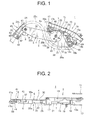
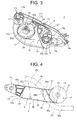
Fig. 1 is a front view illustrating an embodiment of an arm power supply device according to the invention. -
Fig. 2 is a top view illustrating the arm power supply device. -
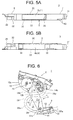
Fig. 3 is a perspective view illustrating an aspect of a base member of the arm power supply device. -
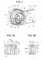
Fig. 4 is a front view illustrating an aspect of a first arm of the arm power supply device in which main portions are drawn in cross-sectional view. -
Fig. 5A is a top view illustrating the first arm. -
Fig. 5B is a bottom view illustrating the first arm. -
Fig. 6 is a front view illustrating an operation of the arm power supply device (a state when a sliding door is closed) . -
Fig. 7 is a perspective view illustrating an internal structure in which a spring member is included on a rotational base end side of the first arm. -
Fig. 8A is a cross-sectional view taken along line A-A ofFig. 7 diagram. -
Fig. 8B is a cross-sectional view taken along line B-B ofFig. 7 . -
Figs. 1 and 2 illustrate an embodiment of an arm power supply device according to the invention. - The arm
power supply device 1 is configured to include a small syntheticresin base member 2 which is vertically fixed to a metal door inner panel 10 (Fig. 2 ) of a sliding door of an automobile, a long synthetic resinfirst arm 3 which is rotatably and axially supported to thebase member 2 in the upward and downward direction and has anenclosure portion 5 in the center forming aslit 4 for inserting a wire harness, and a short synthetic resinsecond arm 8 which is rotatably and axially supported to arotation tip 6 of thefirst arm 3 in the upward and downward direction and has aharness fixing portion 58 on a rotation tip side of its own. - The arm
power supply device 1 in this example is used for the sliding door of the left side of a vehicle, a near side inFig. 1 indicates a vehicle outside (a side near thedoor panel 10 ofFig. 2 ) and a deep side indicates a vehicle inside (a side near adoor trim 11 ofFig. 2 ). The left side (a side near the first arm 3) ofFig. 1 indicates the front side of the vehicle and the right side (a side near the base member 2) indicates the back side of the vehicle.Figs. 1 and 2 illustrate a state in which thefirst arm 3 is urged upward by an urging force of the spring member 9 (Fig. 7 ) on the rotationalbase end side 7 at the time when the sliding door is half open and a harness extra length is absorbed. - As illustrated in
Figs. 1 and 2 , thebase member 2 is formed to have a longitudinal length almost the same degree as the entire length of thefirst arm 3 and a vertical length almost twice times the width of thefirst arm 3, and is miniaturized in the longitudinal and vertical directions. The thickness of thebase member 2 is almost one and half times the thickness of thefirst arm 3, and is compacted in the width direction.Fig. 3 illustrates an embodiment of thebase member 2. - As illustrated in
Figs. 1 and3 , thebase member 2 includes abase plate 12 which is substantially perpendicular in the vertical direction, anupper wall 13 which is inclined downward along the upper end of thebase plate 12, apartition wall 15 which is disposed below theupper wall 13 with a harness guide (insertion)path 14 formed therebetween, a bottomedcylindrical fixing portion 16 which is provided on the lower end side of a bentrear portion 15a of thepartition wall 15, a bottomedcylindrical fixing portion 17 which is provided on the upper end side of the front part of thepartition wall 15 and also serves as a stopper to regulate an upward rotation angle (the clockwise direction) of the first arm 3 (Fig. 1 ), aninclined wall 18 which is inclined upward from thefixing portion 16 on the lower side and serves as a stopper to regulate a downwardly rotation angle (the counterclockwise direction) of thefirst arm 3, a fixing clip 19 (Figs. 1 and 2 ) which is provided between theinclined wall 18 and the rearsemi-bent portion 15a of thepartition wall 15, a shaft 20 (Fig. 3 ) which protrudes from thebase plate 12 and supports the first arm, and aguide wall 21 which is formed at a low height in a substantially annular shape. - The
fixing portions base member 2 respectively includebolt insertion holes bottom walls Fig. 2 , thebottom walls portions inner panel 10 to be fastened and fixed by bolts and nuts (not illustrated), and thelocking clip 19 passes through a hole (not illustrated) formed in the doorinner panel 10 for engagement. The fixingportions base plate 12 of thebase member 2 toward the doorinner panel 10, the rotationalbase end portion 7 in the annular shape (a circular shape in front view) of thefirst arm 3 is positioned in a nearly fan-shaped concave space (use symbol 12 in substitution) between the fixingportions base plate 12, and anouter surface 22 of thefirst arm 3 slightly recedes to thebase plate 12 compared to thebottom walls portions - The
shaft 20 of thebase member 2 includes aslit 20a (Fig. 3 ) which is flexible inward in a radial direction, and has a lockingclaw 20b at the tip. At the time when the shaft passes through a hole portion 23 (Fig. 4 ) on the base end side of thefirst arm 3, the lockingclaw 20b (Fig. 3 ) is engaged with the peripheral of thehole portion 23. Ashaft 24 provided in the second arm 8 (Fig. 1 ) is also configured to be engaged with a hole portion 25 (Fig. 4 ) on the tip side of thefirst arm 3. Acylindrical wall portion 26 is provided in the surrounding area of theshaft 2 0 (Fig. 3 ) of thebase member 2, and a guideperipheral wall 21 is provided on the outside thereof.Symbol 27 denoted inFig. 3 indicates a portion on which thelocking clip 19 is mounted. - The harness guide path 14 (
Fig. 3 ) of thebase member 2 is vertically branched in a short distance on the rear end side (upper and lower branch passages are denoted bysymbols Fig. 1 , a main body (denoted by symbol 28) of awire harness 28 passes through the lower side slightly lower than the lower end of thebase plate 12 of thebase member 2 along thelower branch passage 14b from theharness guide path 14, and then wired along thesecond arm 8 through theslit 4 in theenclosure portion 5 of thefirst arm 3 while being bent in an approximate S shape. Onewire harness 28 is wired from theharness guide path 14 toward the sliding door side, and theother wire harness 28 is wired from thesecond arm 8 up to a harness supporter (not illustrated) on a vehicle body side. Thewire harness 28 is fixed by a binding band (not illustrated) in the branch passage (the harness fixing portion) 14b on the lower side of the harness guide path 14 (a band insertion hole is denoted by symbol 29), and is interposed and fixed by a cover portion (the harness fixing portion) 58 on a rotation tip side of thesecond arm 8. - The first arm 3 includes wall surfaces 22a and 30a (
Fig. 2 ) which are flat and straight on front and back sides (outside and inside), an annular portion (the annular shape wall) 31 (Fig. 1 ) which is formed straight in the surrounding area of a circular wall portion 48 on the same plane as the wall surface 22a on the front side and has a depth equal to the interval of the wall surfaces 22a and 30a on the front side, a portion on the rotation tip side 6 which is formed continuously on the same plane as the wall surface 22a on the front side and connected to the wall surface 30a on the back side through a step portion 32 (Fig. 2 ) while the tip width is tapered, the slit 4 which is formed between the annular portion 31 on the rotational base end side and the portion on the rotation tip side 6 to insert the harness between plate wall portions 22 and 30 forming the wall surfaces 22a and 30a on the front and back sides, plate inclined wall portions (the inclined walls) 35 and 36 which are formed in the front and rear parts and intersect with the plate wall portions 22 and 30 on the front and back sides to form the inner surfaces in the front and rear parts of the slit 4, and the enclosure portion 5 which is surrounded on all sides by the wall portions 22, 30, 35, and 36. - Similarly to an embodiment of the
first arm 3 illustrated inFigs. 4 ,5(a), and 5(b) , theslit 4 surrounded on all sides by theplate wall portions enclosure portion 5 is formed in an approximate chevron shape (the taper shape) in vertically cross-sectional view such that anopening 4b on the lower end side is widened and anopening 4a on the upper end side is narrowed when thefirst arm 3 is substantially horizontally positioned. Theslit 4 is formed by being surrounded by theplate wall portions walls enclosure portion 5. - The
inclined wall 35 on the front side (near the rotation tip) of theenclosure portion 5 includes a straight inner wall surface (use symbol 35 in substitution) and a small-radiusbent surface 35a on the upper and lower ends (on the sides near the upper andlower openings inner wall surface 35. Anouter wall surface 35b of theinclined wall 35 on the front side is connected to the step wall 32 (Fig. 5 ) on the rotation tip side through arib 37. Theinclined wall 36 on the rear side (near the rotational end side) is configured by an arc-shape wall portion 36a which is a part of the lower half portion of the circularannular wall 31 on the rotational base end side and a straight wall portion (use symbol 36 in substitution) which is straightly extended from the arc-shape wall portion 36a in a tangential direction, and the upper end (a portion on theopening 4a side on the upper side) of thestraight wall portion 36 has a small-radius bent surface (end portion) 36b. On thenarrow opening 4a side on the upper side of theslit 4, is formed aconcave portion 47 having almost the triangle shape between thestraight wall portion 36 and anannular wall 31 on the base end side. - In the
first arm 3 ofFig. 4 as an example, a longitudinal length of theopening 4a on the upper side of theslit 4 is slightly shorter than a total sum of lengths of theinclined walls opening 4b on the lower side of theslit 4 is longer than a total sum of lengths of theinclined walls - As illustrated in
Figs. 5(a) and 5(b) , acylindrical bearing member 38 is integrally provided in thestep portion 32 on the rear side of therotation tip 6 of thefirst arm 3 to support theshaft 24 of the second arm 8 (Fig. 1 ) to be freely rotated. Further, anotch portion 40 is provided in the latter half of theannular wall 31 on the rotational base end side of thefirst arm 3 such that oneend portion 9a of the spring member (the torsion coil spring) 9 ofFig. 7 is made to protrude to be engaged with aconcave portion 39 of thepartition wall 15 of thebase member 2 ofFig. 1 . - As illustrated in
Figs. 1, 2 ,4 , and6 , since thewire harness 28 is inserted (passing through) into theslit 4 of thefirst arm 3, thewire harness 28 freely moves in the longitudinal direction of thefirst arm 3 when thefirst arm 3 rotates according to opening and closing of the sliding door, and the movement of thewire harness 28 to the width direction of thefirst arm 3 is prevented so that the trajectory of thewire harness 28 becomes stable. Therefore, small-radius bending and folding of thewire harness 28 is prevented, so that the bending resistance is improved. - Further, as illustrated in
Figs. 1, 2 ,4 , and5 , since thewall portion 22 on the front (outer) side of theenclosure portion 5 of thefirst arm 3 serves as a cover of the power supply device in the related art, the movement of thewire harness 28 to the outside of the vehicle is regulated (prevented) and the interference between a member (the doorinner panel 10 and the like) on the outside of the vehicle and thewire harness 28. Therefore, the cover used in the related art becomes unnecessary, and thepower supply device 1 is simplified, miniaturized, lowered in cost, and reduced in weight. - Further, as illustrated in
Fig. 5 , theenclosure portion 5 of thefirst arm 3 includes theplate wall portions inclined walls first arm 3 is increased by therespective wall portions enclosure portion 5 and are integrally formed in a surrounding frame shape, and thefirst arm 3 is reduced in weight by the surroundingwall portions first arm 3 is reduced in weight by forming theslit 4 surrounded by theenclosure portion 5. - Further, as illustrated in
Fig. 1 , the front end portion (the peripheral end) 12a of thevertical base plate 12 of thebase member 2 forms the end portion in the bent shape with theshaft 20 of thefirst arm 3 as almost the center, and approaches theinclined wall 36 on the rear side of theperipheral end portion 12a in the bent shape of thefirst arm 3 to be positioned (specifically, slightly protrudes forward from theinclined wall 36 on the rear side) in the vicinity of the upper end (end portion) 36b of theinclined wall 36, and thus thebase member 2 is shortened in the longitudinal direction compared to the related art. Thebent endportion 12a slightly protrudes forward from theinclined wall 36 on the rear side, so that the rotationalbase end portion 7 is reliably supported (received) to thefirst arm 3 by thebase plate 12 and the smooth rotation of thefirst arm 3 is reliably secured. - Further, similarly to the rotation state of the
first arm 3 at the time when the sliding door is completely closed (when the sliding door is slid to the rear side of the vehicle) as illustrated inFig. 6 , an almost-horizontal lower end portion (the peripheral end) 12b formed continuously on the bent end portion (the peripheral end) 12a on the front side of thebase plate 12 of thebase member 2 is positioned in the vicinity of the lower end (theend portion 36b on thenarrow opening 4a of the slit 4) of theinclined wall 36 on the rotational base end side of theenclosure portion 5 of thefirst arm 3, so that thebase member 2 is shortened even in the upward and downward direction compared to the related art. - As illustrated in
Figs. 1 and6 , in a rotation range of thefirst arm 3, the peripheral ends 12a and 12b of thebase member 2 are disposed in the vicinity of theend portion 36 of theenclosure portion 5 on the rotational base end side of thefirst arm 3. With theminiaturized base member 2 as described above, thepower supply device 1 is lowered in cost, reduced in weight, and saves spaces, so that thepower supply device 1 can be reliably mounted in a limited mounting space of the sliding door without interference with other mounted components. - The
first arm 3 inFig. 4 is located at a rotational position substantially at the same level or slightly lower than the time when the sliding door ofFig. 1 is the half-open state, and thewire harness 28 is in contact along theinclined wall 36 on the rear side (the rotational base end side) of theenclosure portion 5 of thefirst arm 3, so that the trajectory of thewire harness 28 is regulated and a bent shape in an approximate S shape of thewire harness 28 ofFig. 1 is maintained. Therefore, the small-radius bending such as the bending of thewire harness 28, and the bending tendency of thewire harness 28 according to the small-radius bending are reliably prevented. The inner surface of theinclined wall 36 on the rear side serves as a contact surface for guiding thewire harness 28. - As illustrated in
Fig. 1 , while being bent downward in the approximate semicircular shape from the harness fixing portion (the branch passage) 14b on a side near the rear portion of thebase member 2, thewire harness 28 passes through theslit 4 in theenclosure portion 5 of thefirst arm 3 from the downwardlybent portion 28a (the harness insertion portion is denoted bysymbol 28b) and bent upward in the approximate semicircular shape (the upwardly bent portion is denoted bysymbol 28c), and is fixed by the binding band which is the harness fixing portion on the rotation tip side of the second arm 8 (the band insertion hole is denoted by symbol 45) and thecover portion 58 while being wired in the bent shape along the second arm 8 (the harness wired portion is denoted bysymbol 28d). - As illustrated in
Figs. 1 and 2 , thesecond arm 8 is formed to have about the half or slightly shorter than the length of thefirst arm 3, includes abent gutter portion 41 on the front side (the upper side), abase wall 42 which is approximately straight on the rear side (the lower side), theshaft 24 which protrudes to the base end side of thebase wall 42, and thecover portion 58 having a semicircular shape in cross-sectional view which is provided to be opened and closed by athin hinge 41b in aportion 41a (Fig. 2 ) having a semicircular shape in cross-sectional view on the rotation tip side of thegutter portion 41. Thecover portion 58 is engaged with thebase wall 42 in a state of being closed by an engagement means (a claw portion and a hole portion) 43. Thegutter portion 41 is offset from theshaft 24 to the front side (the upper side). - The
wire harness 28, for example, wraps the end portion of thecorrugate tube 60 through a tape winding portion (not illustrated) on an outer peripheral side of the end portion of themesh tube 59 to be interposed and fixed into thecover portion 58 in a state where a plurality of electric lines are covered with a small-radius synthetic resin mesh tube (protection tube) 59 having a good bending property in a range from thebase member 2 to thecover portion 58 of thesecond arm 8 and the plurality of electric lines are covered with a large-radius synthetic resin corrugate tube (protection tube) 60 also in a range from thecover portion 58 to the harness supporter on a side near the vehicle body through a connection portion between the sliding door and the vehicle body. In the inner surface of thecover portion 58 and in the facing inner surface of thegutter portion 41, a sharp projection may be provided to pass and fix the end portion of thecorrugate tube 60 and the tape winding portion of the end portion of themesh tube 59. As illustrated inFig. 2 , thebase wall 42 of thesecond arm 8 is positioned in thestep portion 32 on the rotation tip side of thefirst arm 3, a circularharness insertion space 44 in thecover portion 58 is positioned collinearly (on a vertical plane) to theslit 4 for inserting the harness of thefirst arm 3, and thewire harness 28 is bent in the upward and downward direction without deviation in position in the right and left direction from thecover portion 58 to theslit 4. - In a half-open state of the sliding door of
Fig. 1 , thefirst arm 3 is urged upward by an urging force of thespring member 9, the bentupper wall surface 46 on the front side formed continuously on theannular wall 31 on the base end side of thefirst arm 3 is in contact with the bent lower surface of the cylindrical fixingportion 17 on the front side of thebase member 2, the upward rotation of thefirst arm 3 is prevented, thewire harness 28 is lifted up together with thefirst arm 3, and thebent harness portion 28a is prevented from being hanging down along thelower end 12b of thebase member 2. Thefirst arm 3 is slightly inclined upward from the horizontal level, thesecond arm 8 is inclined downward, and an angle α formed between botharms - When the sliding door is further slid from the state of
Fig. 1 to the rear side of the vehicle to be completely opened (thepower supply device 1 retreats integrally with the sliding door), thewire harness 28 is pulled from the harness supporter (rotation clamp) (not illustrated) on the front side of the vehicle body with respect to thesecond arm 8, thesecond arm 8 rotates upward (the clockwise direction) about theshaft 24 on the base end side, thefirst arm 3 rotates downward (the counterclockwise direction) about theshaft 20 on the base end side, and both thearms - At this time, the
wire harness 28 is further extended in a straight line compared toFig. 1 , theharness portion 28b passed through in theslit 4 of thefirst arm 3 is in contact along theinclined wall 36 on the rear side of theslit 4 to be inclined upward as illustrated inFig. 4 , and theharness portion 28c on the upper side formed continuously on theinclined harness portion 28b and theharness portion 28a on the lower side are smoothly bent in a large radius, so that a small-radius bending which adversely affects thewire harness 28 is prevented and the bending resistance of thewire harness 28 is increased. - When the sliding door is slid from the half-open state of
Fig. 1 to the front side of the vehicle to be completely closed, as illustrated inFig. 6 , thewire harness 28 is pulled to the rear side from the harness supporter (not illustrated) on the rear side of the vehicle body, thefirst arm 3 rotates downward about theshaft 20 on the base end side (the counterclockwise direction), and thesecond arm 8 rotates about theshaft 24 on the base end side to be substantially horizontal and slightly upward (the counterclockwise direction) on the lower side of thefirst arm 3. For example, the harness supporter (not illustrated) on a side near the vehicle body is disposed to the rear side to be separated from arotation tip 58a of thesecond arm 8 ofFig. 6 by a distance equal to about two or more times the entire lengthof thefirst arm 3 tobe substantially horizontal. The open angle formed between the botharms Fig. 6 is an obtuse angle of about 90°. - As illustrated in
Fig. 6 , thewire harness 28 is bent forward from afront end 41c of thegutter portion 41 of the second arm 8 (the forward bent portion is denoted bysymbol 28e), passes through theslit 4 in theenclosure portion 5 of the first arm 3 (the insertion portion passing through theslit 4 is denoted bysymbol 28f), bent upward on the rear side of the first arm 3 (the upwardly bent portion is denoted bysymbol 28g), and connected to theharness fixing portion 14b on the lower rear side of thebase member 2. InFig. 6 , theinclined wall 35 on the rotation tip side of theslit 4 of thefirst arm 3 is positioned substantially horizontal, and makes thewire harness 28 smoothly inserted in theslit 4 without causing interference with theinclined wall 35. - In an internal structure of the rotational
base end portion 7 of thefirst arm 3 illustrated inFig. 7 , the annular wall (the peripheral wall) 31 is provided in the surrounding area of the circular wall portion (the bottom wall) 48 formed flush with thewall portion 22 on the surface side of thefirst arm 3, the edge portion on the front side of anopening 49 of theannular wall 31 is integrally connected to thewall portion 30 on the rear side of thefirst arm 3, and ahole portion 50 is provided to pass through theshaft 20 of thebase member 2 ofFig. 3 for engagement at the center of thebottom wall 48. - Furthermore, a
cylindrical wall 51 is provided to pass through the surrounding area of thehole portion 50 and engaged with the inner side of thecylindrical wall 26 of the surrounding area of theshaft 20 of thebase member 2 ofFig. 3 to be freely rotated, a large-radius innerperipheral wall 52 in the substantially annular shape which is partially notched and decentered toward theopening 4b side as wide as the width of theslit 4 is provided in the surrounding area of thecylindrical wall 51,hollow column walls peripheral wall 52, and acoil portion 9b of thetorsion coil spring 9 is contained between the innerperipheral wall 52 and an outer peripheral wall (the annular wall) 31 with a gap from theopening 49 and onestraight endportion 9c which is bent inward thetorsion coil spring 9 is inserted between thecolumn walls - As illustrated in
Figs. 8 (a) and 8 (b) , in thecolumn wall 53, the flexible engagement arm (the engagement portion) 55 is integrally notched (theengagement arm 55 is separated from thecolumn wall 53 by theslit 56 in the surrounding area), theengagement arm 55 includes aprojection 55b on a side near a tip (free end) 55a in a near portion of thebottom wall 48 of theannular portion 31, and theprojection 55b protrudes in agap 57 between thecolumn walls projection 55b includes anengagement surface 55b1 which is disposed to face the bottom wall 48 (specifically, a die punchedhole 48a) of theannular portion 31 and parallel to thebottom wall 48 and aguide inclining surface 55b2 which faces the root (base end) 55c of theengagement arm 55 from theengagement surface 55b1, and thetip portion 55a of the straightengagement arm body 55 perpendicular to theengagement surface 55b1 protrudes toward thebottom wall 48. Oneend portion 9c of thetorsion coil spring 9 is formed to go over theprojection 55b of theengagement arm 55 and inserted between thecolumn walls projection 55b to prevent uncoiling. - Therefore, the entire
torsion coil spring 9 is engaged by oneengagement arm 55 , and in a case where an operator assembles thefirst arm 3 mounted with thetorsion coil spring 9 to theshaft 20 of the base member 2 (Fig. 3 ), even when theopening 49 of theannular wall 31 of thefirst arm 3 moves downward, it is prevented that thetorsion coil spring 9 is fallen out of theannular wall 31, and assembly workability of thefirst arm 3 with thetorsion coil spring 9 to thebase member 2 is improved. - As illustrated in
Fig. 7 , theother end portion 9a of thetorsion coil spring 9 is extended straight longer than oneend portion 9c in a tangential direction of acoil winding portion 9b and passes through thenotch portion 40 in the edge of theopening 49 of theannular wall 31 of thefirst arm 3 and anotch portion 21a of the lowerannual wall 21 of thebase member 2 ofFig. 3 , and theextension tip portion 9a is bent outward and engaged with the groove (the concave portion) 39 on thepartition wall 15 side of thebase member 2 ofFig. 3 . Theinner edge portion 49 on the opening side of theannular wall 31 of thefirst arm 3 is rotatably guided along the outer peripheral surface of theannual wall 21 of thebase member 2. - When the sliding door is closed as illustrated in
Fig. 6 , thetorsion coil spring 9 ofFig. 7 is pulled by the rotation in the counterclockwise direction of thefirst arm 3 while the radius is reduced, and when the sliding door is opened as illustrated inFig. 2 , thefirst arm 3 is urged upward in the clockwise direction by a restoring force (elastic force) while the radius is increased. - In addition, the embodiment has been described about the sliding door on the left side of the vehicle, and the sliding door on the right side of the vehicle has the same configurations and actions except that the arrangement is symmetrical to the sliding door on the left side. Further, as a using method of the
torsion coil spring 9, thetorsion coil spring 9 may be pulled at the time of closing the sliding door while the radius is increased, and thetorsion coil spring 9 may be restored at the time of opening the sliding door while the radius is reduced. - Further, the state when the sliding door is closed may be set to a state similar to a mirror-inverted (front and rear) state of
Fig. 1 , and the state when the sliding door is opened may be set to a state similar to a mirror-inverted (front and rear) state ofFig. 6 . When the sliding door is closed (a period of time longer than the time when the sliding door is opened), thetorsion coil spring 9 is recovered to a substantially free state, so that the stress on thetorsion coil spring 9 is reduced. This configuration is desirable for a case where thewire harness 28 is slightly hanging down at the time when the sliding door is the half-open state. - Further, the arm power supply device may be applied to the sliding door of a vehicle other than that of automobile and the sliding door of an apparatus other than that of the vehicle. The sliding door is collectively referred to as a sliding structure, and the vehicle body and the apparatus body are collectively referred to as a fixed structure.
- The arm power supply device according to the invention can be used to prevent the bending of the arm in the width direction, resolve the rattling of the wire harness and the instability of the trajectory, and improve the bending resistance of the wire harness. Furthermore, the structure of the power supply device can be miniaturized while eliminating the cover member. In addition, the spring member can be prevented from falling out of the arm.
-
- 1: Arm power supply device
- 2: Base member
- 3: First arm
- 4: Slit
- 5: Enclosure portion
- 6: Rotation tip side
- 8: Second arm
- 9: Torsion coil spring
- 9c: One end
- 12a, 12b: Peripheral end
- 14b: Branch passage (harness fixing portion)
- 28: Wire harness
- 36: Inclined wall
- 36b: End portion
- 55: Engagement arm (engagement portion)
- 58: Cover portion (harness fixing portion)
Claims (4)
- An arm power supply device in which a first arm is rotatably and axially supported to a base member having one harness fixing portion, a second arm having the other harness fixing portion is rotatably and axially supported on a rotation tip side of the first arm, the first arm includes an enclosure portion forming a slit through which a wire harness is inserted, and the wire harness passes from the base member to the slit and is wired over the second arm.
- The arm power supply device according to claim 1, wherein
the enclosure portion includes an inclined wall on a rotational base end side of the first arm such that the wire harness derived in a bent shape from the second arm is guided to be in contact with an inner surface. - The arm power supply device according to claim 1 or 2, wherein
a peripheral end of the base member is disposed in the vicinity of anendportionof the enclosure portion on a rotational base end side of the first arm in a rotation range of the first arm. - The arm power supply device according to any one of claims 1 to 3, wherein
a torsion coil spring to urge the first arm in a rotation direction is contained on a rotational base end side of the first arm, and an engagement portion to engage one end portion of the torsion coil spring is provided on the rotational base end side.
Applications Claiming Priority (2)
| Application Number | Priority Date | Filing Date | Title |
|---|---|---|---|
| JP2012158594A JP5892602B2 (en) | 2012-07-17 | 2012-07-17 | Arm feeder |
| PCT/JP2013/069243 WO2014013964A1 (en) | 2012-07-17 | 2013-07-16 | Arm power supply device |
Publications (3)
| Publication Number | Publication Date |
|---|---|
| EP2876760A1 true EP2876760A1 (en) | 2015-05-27 |
| EP2876760A4 EP2876760A4 (en) | 2016-03-23 |
| EP2876760B1 EP2876760B1 (en) | 2017-09-06 |
Family
ID=49948791
Family Applications (1)
| Application Number | Title | Priority Date | Filing Date |
|---|---|---|---|
| EP13819277.8A Not-in-force EP2876760B1 (en) | 2012-07-17 | 2013-07-16 | Arm power supply device |
Country Status (5)
| Country | Link |
|---|---|
| US (1) | US9725053B2 (en) |
| EP (1) | EP2876760B1 (en) |
| JP (1) | JP5892602B2 (en) |
| CN (1) | CN104471811B (en) |
| WO (1) | WO2014013964A1 (en) |
Families Citing this family (9)
| Publication number | Priority date | Publication date | Assignee | Title |
|---|---|---|---|---|
| JP5892604B2 (en) * | 2012-07-17 | 2016-03-23 | 矢崎総業株式会社 | Arm feeder |
| JP5892603B2 (en) * | 2012-07-17 | 2016-03-23 | 矢崎総業株式会社 | Arm feeder |
| JP6211375B2 (en) * | 2013-10-11 | 2017-10-11 | 矢崎総業株式会社 | Power supply device |
| FR3081832B1 (en) * | 2018-06-04 | 2021-05-21 | Safran Landing Systems | AIRCRAFT LANDING EQUIPPED WITH CABLE AND PIPE ROUTING |
| JP7179712B2 (en) * | 2019-12-26 | 2022-11-29 | 株式会社東芝 | disk device |
| JP7088976B2 (en) * | 2020-03-24 | 2022-06-21 | 矢崎総業株式会社 | Wire harness wiring structure |
| JP7319217B2 (en) * | 2020-03-30 | 2023-08-01 | 矢崎総業株式会社 | Protector and wire harness routing structure |
| JP7321209B2 (en) * | 2021-05-13 | 2023-08-04 | 矢崎総業株式会社 | Protector, wire harness, and wire harness assembly method |
| EP4292885B1 (en) * | 2022-06-17 | 2024-07-24 | Volvo Truck Corporation | Retaining system for electrical cables of an industrial vehicle |
Family Cites Families (14)
| Publication number | Priority date | Publication date | Assignee | Title |
|---|---|---|---|---|
| JP3348765B2 (en) * | 1996-08-08 | 2002-11-20 | 矢崎総業株式会社 | Routing structure of door harness |
| JP2000211446A (en) * | 1999-01-26 | 2000-08-02 | Sumitomo Wiring Syst Ltd | Protector for wire harness distributed in door opening/ closing part of automobile |
| JP4092086B2 (en) * | 2000-06-30 | 2008-05-28 | 矢崎総業株式会社 | Corrugated tube fixture |
| JP4392393B2 (en) | 2005-08-31 | 2009-12-24 | 矢崎総業株式会社 | Harness support for constant power supply and harness routing structure using the same |
| JP4758850B2 (en) * | 2006-08-14 | 2011-08-31 | 矢崎総業株式会社 | Wiring harness wiring structure to link |
| JP4783307B2 (en) * | 2006-11-13 | 2011-09-28 | 矢崎総業株式会社 | Power feeding device for slide structure |
| JP5090831B2 (en) * | 2007-09-10 | 2012-12-05 | 矢崎総業株式会社 | Power feeding device for slide structure |
| JP4997060B2 (en) * | 2007-10-16 | 2012-08-08 | 矢崎総業株式会社 | Feed structure for slide structure |
| JP5308889B2 (en) * | 2009-03-30 | 2013-10-09 | 矢崎総業株式会社 | Power feeding device for slide structure |
| JP2010233426A (en) * | 2009-03-30 | 2010-10-14 | Yazaki Corp | Power feeding device for slide structure |
| JP5318712B2 (en) * | 2009-09-11 | 2013-10-16 | 矢崎総業株式会社 | Arm feeding structure |
| JP5373516B2 (en) * | 2009-09-11 | 2013-12-18 | 矢崎総業株式会社 | Arm feeding structure |
| JP5758146B2 (en) * | 2011-02-23 | 2015-08-05 | トヨタ車体株式会社 | Guide structure of harness member |
| JP6009257B2 (en) * | 2012-07-20 | 2016-10-19 | 矢崎総業株式会社 | Power supply structure for sliding door |
-
2012
- 2012-07-17 JP JP2012158594A patent/JP5892602B2/en active Active
-
2013
- 2013-07-16 CN CN201380037847.0A patent/CN104471811B/en active Active
- 2013-07-16 WO PCT/JP2013/069243 patent/WO2014013964A1/en not_active Ceased
- 2013-07-16 EP EP13819277.8A patent/EP2876760B1/en not_active Not-in-force
-
2014
- 2014-12-30 US US14/585,453 patent/US9725053B2/en active Active
Also Published As
| Publication number | Publication date |
|---|---|
| JP5892602B2 (en) | 2016-03-23 |
| CN104471811B (en) | 2017-08-04 |
| US9725053B2 (en) | 2017-08-08 |
| WO2014013964A1 (en) | 2014-01-23 |
| EP2876760A4 (en) | 2016-03-23 |
| EP2876760B1 (en) | 2017-09-06 |
| JP2014023246A (en) | 2014-02-03 |
| US20150108289A1 (en) | 2015-04-23 |
| CN104471811A (en) | 2015-03-25 |
Similar Documents
| Publication | Publication Date | Title |
|---|---|---|
| EP2876760B1 (en) | Arm power supply device | |
| EP2876762A1 (en) | Arm power supply device | |
| EP2876763A1 (en) | Arm power supply device | |
| US7202415B2 (en) | Wire harness construction | |
| EP2950408B1 (en) | Spring section protection structure for power supply device | |
| US9771034B2 (en) | Power supply device | |
| EP2551979A1 (en) | Electricity-feeding wiring structure | |
| JP5925198B2 (en) | Window regulator | |
| EP2045139A2 (en) | Harness protector structure for link | |
| JP2009194990A (en) | Power feeding device for slide structure | |
| EP3124300A1 (en) | Sunroof device | |
| JP5424468B2 (en) | Wiring harness wiring structure | |
| JP6268006B2 (en) | Harness equipment | |
| JP4631791B2 (en) | Electrical junction box for automobile | |
| JP5961858B2 (en) | Vehicle door sash structure | |
| JP5706202B2 (en) | Roller unit | |
| JP2019090472A (en) | Cables protection guide device and its attachment structure | |
| JP4396388B2 (en) | Protector | |
| JP2009056911A (en) | Holder for wire harness | |
| JP4591373B2 (en) | Harness protector | |
| JP6444250B2 (en) | Electrical equipment storage box | |
| JP2008099499A (en) | Extra length absorber | |
| JP2019149919A (en) | Protector and manufacturing method of protector | |
| JP2015063817A (en) | Outer tube bearing member for wire type window regulator |
Legal Events
| Date | Code | Title | Description |
|---|---|---|---|
| PUAI | Public reference made under article 153(3) epc to a published international application that has entered the european phase |
Free format text: ORIGINAL CODE: 0009012 |
|
| 17P | Request for examination filed |
Effective date: 20150216 |
|
| AK | Designated contracting states |
Kind code of ref document: A1 Designated state(s): AL AT BE BG CH CY CZ DE DK EE ES FI FR GB GR HR HU IE IS IT LI LT LU LV MC MK MT NL NO PL PT RO RS SE SI SK SM TR |
|
| AX | Request for extension of the european patent |
Extension state: BA ME |
|
| DAX | Request for extension of the european patent (deleted) | ||
| RA4 | Supplementary search report drawn up and despatched (corrected) |
Effective date: 20160223 |
|
| RIC1 | Information provided on ipc code assigned before grant |
Ipc: H02G 11/00 20060101AFI20160217BHEP Ipc: B60R 16/02 20060101ALI20160217BHEP |
|
| 17Q | First examination report despatched |
Effective date: 20170130 |
|
| GRAP | Despatch of communication of intention to grant a patent |
Free format text: ORIGINAL CODE: EPIDOSNIGR1 |
|
| INTG | Intention to grant announced |
Effective date: 20170509 |
|
| GRAS | Grant fee paid |
Free format text: ORIGINAL CODE: EPIDOSNIGR3 |
|
| GRAA | (expected) grant |
Free format text: ORIGINAL CODE: 0009210 |
|
| AK | Designated contracting states |
Kind code of ref document: B1 Designated state(s): AL AT BE BG CH CY CZ DE DK EE ES FI FR GB GR HR HU IE IS IT LI LT LU LV MC MK MT NL NO PL PT RO RS SE SI SK SM TR |
|
| REG | Reference to a national code |
Ref country code: GB Ref legal event code: FG4D |
|
| REG | Reference to a national code |
Ref country code: CH Ref legal event code: EP Ref country code: AT Ref legal event code: REF Ref document number: 926861 Country of ref document: AT Kind code of ref document: T Effective date: 20170915 |
|
| REG | Reference to a national code |
Ref country code: IE Ref legal event code: FG4D |
|
| REG | Reference to a national code |
Ref country code: DE Ref legal event code: R096 Ref document number: 602013026324 Country of ref document: DE |
|
| REG | Reference to a national code |
Ref country code: NL Ref legal event code: MP Effective date: 20170906 |
|
| REG | Reference to a national code |
Ref country code: LT Ref legal event code: MG4D |
|
| PG25 | Lapsed in a contracting state [announced via postgrant information from national office to epo] |
Ref country code: SE Free format text: LAPSE BECAUSE OF FAILURE TO SUBMIT A TRANSLATION OF THE DESCRIPTION OR TO PAY THE FEE WITHIN THE PRESCRIBED TIME-LIMIT Effective date: 20170906 Ref country code: FI Free format text: LAPSE BECAUSE OF FAILURE TO SUBMIT A TRANSLATION OF THE DESCRIPTION OR TO PAY THE FEE WITHIN THE PRESCRIBED TIME-LIMIT Effective date: 20170906 Ref country code: HR Free format text: LAPSE BECAUSE OF FAILURE TO SUBMIT A TRANSLATION OF THE DESCRIPTION OR TO PAY THE FEE WITHIN THE PRESCRIBED TIME-LIMIT Effective date: 20170906 Ref country code: LT Free format text: LAPSE BECAUSE OF FAILURE TO SUBMIT A TRANSLATION OF THE DESCRIPTION OR TO PAY THE FEE WITHIN THE PRESCRIBED TIME-LIMIT Effective date: 20170906 Ref country code: NO Free format text: LAPSE BECAUSE OF FAILURE TO SUBMIT A TRANSLATION OF THE DESCRIPTION OR TO PAY THE FEE WITHIN THE PRESCRIBED TIME-LIMIT Effective date: 20171206 |
|
| REG | Reference to a national code |
Ref country code: AT Ref legal event code: MK05 Ref document number: 926861 Country of ref document: AT Kind code of ref document: T Effective date: 20170906 |
|
| PG25 | Lapsed in a contracting state [announced via postgrant information from national office to epo] |
Ref country code: ES Free format text: LAPSE BECAUSE OF FAILURE TO SUBMIT A TRANSLATION OF THE DESCRIPTION OR TO PAY THE FEE WITHIN THE PRESCRIBED TIME-LIMIT Effective date: 20170906 Ref country code: RS Free format text: LAPSE BECAUSE OF FAILURE TO SUBMIT A TRANSLATION OF THE DESCRIPTION OR TO PAY THE FEE WITHIN THE PRESCRIBED TIME-LIMIT Effective date: 20170906 Ref country code: BG Free format text: LAPSE BECAUSE OF FAILURE TO SUBMIT A TRANSLATION OF THE DESCRIPTION OR TO PAY THE FEE WITHIN THE PRESCRIBED TIME-LIMIT Effective date: 20171206 Ref country code: LV Free format text: LAPSE BECAUSE OF FAILURE TO SUBMIT A TRANSLATION OF THE DESCRIPTION OR TO PAY THE FEE WITHIN THE PRESCRIBED TIME-LIMIT Effective date: 20170906 Ref country code: GR Free format text: LAPSE BECAUSE OF FAILURE TO SUBMIT A TRANSLATION OF THE DESCRIPTION OR TO PAY THE FEE WITHIN THE PRESCRIBED TIME-LIMIT Effective date: 20171207 |
|
| PG25 | Lapsed in a contracting state [announced via postgrant information from national office to epo] |
Ref country code: NL Free format text: LAPSE BECAUSE OF FAILURE TO SUBMIT A TRANSLATION OF THE DESCRIPTION OR TO PAY THE FEE WITHIN THE PRESCRIBED TIME-LIMIT Effective date: 20170906 |
|
| PG25 | Lapsed in a contracting state [announced via postgrant information from national office to epo] |
Ref country code: RO Free format text: LAPSE BECAUSE OF FAILURE TO SUBMIT A TRANSLATION OF THE DESCRIPTION OR TO PAY THE FEE WITHIN THE PRESCRIBED TIME-LIMIT Effective date: 20170906 Ref country code: PL Free format text: LAPSE BECAUSE OF FAILURE TO SUBMIT A TRANSLATION OF THE DESCRIPTION OR TO PAY THE FEE WITHIN THE PRESCRIBED TIME-LIMIT Effective date: 20170906 Ref country code: CZ Free format text: LAPSE BECAUSE OF FAILURE TO SUBMIT A TRANSLATION OF THE DESCRIPTION OR TO PAY THE FEE WITHIN THE PRESCRIBED TIME-LIMIT Effective date: 20170906 |
|
| PG25 | Lapsed in a contracting state [announced via postgrant information from national office to epo] |
Ref country code: IT Free format text: LAPSE BECAUSE OF FAILURE TO SUBMIT A TRANSLATION OF THE DESCRIPTION OR TO PAY THE FEE WITHIN THE PRESCRIBED TIME-LIMIT Effective date: 20170906 Ref country code: EE Free format text: LAPSE BECAUSE OF FAILURE TO SUBMIT A TRANSLATION OF THE DESCRIPTION OR TO PAY THE FEE WITHIN THE PRESCRIBED TIME-LIMIT Effective date: 20170906 Ref country code: SM Free format text: LAPSE BECAUSE OF FAILURE TO SUBMIT A TRANSLATION OF THE DESCRIPTION OR TO PAY THE FEE WITHIN THE PRESCRIBED TIME-LIMIT Effective date: 20170906 Ref country code: IS Free format text: LAPSE BECAUSE OF FAILURE TO SUBMIT A TRANSLATION OF THE DESCRIPTION OR TO PAY THE FEE WITHIN THE PRESCRIBED TIME-LIMIT Effective date: 20180106 Ref country code: SK Free format text: LAPSE BECAUSE OF FAILURE TO SUBMIT A TRANSLATION OF THE DESCRIPTION OR TO PAY THE FEE WITHIN THE PRESCRIBED TIME-LIMIT Effective date: 20170906 Ref country code: AT Free format text: LAPSE BECAUSE OF FAILURE TO SUBMIT A TRANSLATION OF THE DESCRIPTION OR TO PAY THE FEE WITHIN THE PRESCRIBED TIME-LIMIT Effective date: 20170906 |
|
| REG | Reference to a national code |
Ref country code: DE Ref legal event code: R097 Ref document number: 602013026324 Country of ref document: DE |
|
| REG | Reference to a national code |
Ref country code: FR Ref legal event code: PLFP Year of fee payment: 6 |
|
| PLBE | No opposition filed within time limit |
Free format text: ORIGINAL CODE: 0009261 |
|
| STAA | Information on the status of an ep patent application or granted ep patent |
Free format text: STATUS: NO OPPOSITION FILED WITHIN TIME LIMIT |
|
| PG25 | Lapsed in a contracting state [announced via postgrant information from national office to epo] |
Ref country code: DK Free format text: LAPSE BECAUSE OF FAILURE TO SUBMIT A TRANSLATION OF THE DESCRIPTION OR TO PAY THE FEE WITHIN THE PRESCRIBED TIME-LIMIT Effective date: 20170906 |
|
| 26N | No opposition filed |
Effective date: 20180607 |
|
| PG25 | Lapsed in a contracting state [announced via postgrant information from national office to epo] |
Ref country code: SI Free format text: LAPSE BECAUSE OF FAILURE TO SUBMIT A TRANSLATION OF THE DESCRIPTION OR TO PAY THE FEE WITHIN THE PRESCRIBED TIME-LIMIT Effective date: 20170906 |
|
| REG | Reference to a national code |
Ref country code: CH Ref legal event code: PL |
|
| GBPC | Gb: european patent ceased through non-payment of renewal fee |
Effective date: 20180716 |
|
| PG25 | Lapsed in a contracting state [announced via postgrant information from national office to epo] |
Ref country code: LU Free format text: LAPSE BECAUSE OF NON-PAYMENT OF DUE FEES Effective date: 20180716 Ref country code: MC Free format text: LAPSE BECAUSE OF FAILURE TO SUBMIT A TRANSLATION OF THE DESCRIPTION OR TO PAY THE FEE WITHIN THE PRESCRIBED TIME-LIMIT Effective date: 20170906 |
|
| REG | Reference to a national code |
Ref country code: BE Ref legal event code: MM Effective date: 20180731 |
|
| REG | Reference to a national code |
Ref country code: IE Ref legal event code: MM4A |
|
| PG25 | Lapsed in a contracting state [announced via postgrant information from national office to epo] |
Ref country code: LI Free format text: LAPSE BECAUSE OF NON-PAYMENT OF DUE FEES Effective date: 20180731 Ref country code: CH Free format text: LAPSE BECAUSE OF NON-PAYMENT OF DUE FEES Effective date: 20180731 Ref country code: GB Free format text: LAPSE BECAUSE OF NON-PAYMENT OF DUE FEES Effective date: 20180716 Ref country code: IE Free format text: LAPSE BECAUSE OF NON-PAYMENT OF DUE FEES Effective date: 20180716 |
|
| PG25 | Lapsed in a contracting state [announced via postgrant information from national office to epo] |
Ref country code: BE Free format text: LAPSE BECAUSE OF NON-PAYMENT OF DUE FEES Effective date: 20180731 |
|
| PG25 | Lapsed in a contracting state [announced via postgrant information from national office to epo] |
Ref country code: MT Free format text: LAPSE BECAUSE OF NON-PAYMENT OF DUE FEES Effective date: 20180716 |
|
| PG25 | Lapsed in a contracting state [announced via postgrant information from national office to epo] |
Ref country code: TR Free format text: LAPSE BECAUSE OF FAILURE TO SUBMIT A TRANSLATION OF THE DESCRIPTION OR TO PAY THE FEE WITHIN THE PRESCRIBED TIME-LIMIT Effective date: 20170906 |
|
| PG25 | Lapsed in a contracting state [announced via postgrant information from national office to epo] |
Ref country code: PT Free format text: LAPSE BECAUSE OF FAILURE TO SUBMIT A TRANSLATION OF THE DESCRIPTION OR TO PAY THE FEE WITHIN THE PRESCRIBED TIME-LIMIT Effective date: 20170906 Ref country code: HU Free format text: LAPSE BECAUSE OF FAILURE TO SUBMIT A TRANSLATION OF THE DESCRIPTION OR TO PAY THE FEE WITHIN THE PRESCRIBED TIME-LIMIT; INVALID AB INITIO Effective date: 20130716 |
|
| PG25 | Lapsed in a contracting state [announced via postgrant information from national office to epo] |
Ref country code: MK Free format text: LAPSE BECAUSE OF NON-PAYMENT OF DUE FEES Effective date: 20170906 Ref country code: CY Free format text: LAPSE BECAUSE OF FAILURE TO SUBMIT A TRANSLATION OF THE DESCRIPTION OR TO PAY THE FEE WITHIN THE PRESCRIBED TIME-LIMIT Effective date: 20170906 |
|
| PG25 | Lapsed in a contracting state [announced via postgrant information from national office to epo] |
Ref country code: AL Free format text: LAPSE BECAUSE OF FAILURE TO SUBMIT A TRANSLATION OF THE DESCRIPTION OR TO PAY THE FEE WITHIN THE PRESCRIBED TIME-LIMIT Effective date: 20170906 |
|
| PGFP | Annual fee paid to national office [announced via postgrant information from national office to epo] |
Ref country code: FR Payment date: 20230620 Year of fee payment: 11 |
|
| PGFP | Annual fee paid to national office [announced via postgrant information from national office to epo] |
Ref country code: DE Payment date: 20230531 Year of fee payment: 11 |
|
| REG | Reference to a national code |
Ref country code: DE Ref legal event code: R119 Ref document number: 602013026324 Country of ref document: DE |
|
| PG25 | Lapsed in a contracting state [announced via postgrant information from national office to epo] |
Ref country code: DE Free format text: LAPSE BECAUSE OF NON-PAYMENT OF DUE FEES Effective date: 20250201 |
|
| PG25 | Lapsed in a contracting state [announced via postgrant information from national office to epo] |
Ref country code: FR Free format text: LAPSE BECAUSE OF NON-PAYMENT OF DUE FEES Effective date: 20240731 |