EP2876637A2 - Anchoring system for a string in a musical instrument - Google Patents
Anchoring system for a string in a musical instrument Download PDFInfo
- Publication number
- EP2876637A2 EP2876637A2 EP14190262.7A EP14190262A EP2876637A2 EP 2876637 A2 EP2876637 A2 EP 2876637A2 EP 14190262 A EP14190262 A EP 14190262A EP 2876637 A2 EP2876637 A2 EP 2876637A2
- Authority
- EP
- European Patent Office
- Prior art keywords
- string
- ball
- pin
- bridge
- aperture
- Prior art date
- Legal status (The legal status is an assumption and is not a legal conclusion. Google has not performed a legal analysis and makes no representation as to the accuracy of the status listed.)
- Granted
Links
Images



Classifications
-
- G—PHYSICS
- G10—MUSICAL INSTRUMENTS; ACOUSTICS
- G10D—STRINGED MUSICAL INSTRUMENTS; WIND MUSICAL INSTRUMENTS; ACCORDIONS OR CONCERTINAS; PERCUSSION MUSICAL INSTRUMENTS; AEOLIAN HARPS; SINGING-FLAME MUSICAL INSTRUMENTS; MUSICAL INSTRUMENTS NOT OTHERWISE PROVIDED FOR
- G10D1/00—General design of stringed musical instruments
- G10D1/04—Plucked or strummed string instruments, e.g. harps or lyres
- G10D1/05—Plucked or strummed string instruments, e.g. harps or lyres with fret boards or fingerboards
- G10D1/08—Guitars
-
- G—PHYSICS
- G10—MUSICAL INSTRUMENTS; ACOUSTICS
- G10D—STRINGED MUSICAL INSTRUMENTS; WIND MUSICAL INSTRUMENTS; ACCORDIONS OR CONCERTINAS; PERCUSSION MUSICAL INSTRUMENTS; AEOLIAN HARPS; SINGING-FLAME MUSICAL INSTRUMENTS; MUSICAL INSTRUMENTS NOT OTHERWISE PROVIDED FOR
- G10D3/00—Details of, or accessories for, stringed musical instruments, e.g. slide-bars
- G10D3/12—Anchoring devices for strings, e.g. tail pieces or hitchpins
-
- G—PHYSICS
- G10—MUSICAL INSTRUMENTS; ACOUSTICS
- G10D—STRINGED MUSICAL INSTRUMENTS; WIND MUSICAL INSTRUMENTS; ACCORDIONS OR CONCERTINAS; PERCUSSION MUSICAL INSTRUMENTS; AEOLIAN HARPS; SINGING-FLAME MUSICAL INSTRUMENTS; MUSICAL INSTRUMENTS NOT OTHERWISE PROVIDED FOR
- G10D3/00—Details of, or accessories for, stringed musical instruments, e.g. slide-bars
- G10D3/04—Bridges
Definitions
- the present invention relates to musical instruments. More particularly, the invention relates to stringed instruments, like guitars. More particularly still, the invention relates to an anchoring system for guitar strings.
- Figure 1 is a plan view of a 6 string guitar showing the strings 1 anchored at a first end at a head stock 5 where they are tightened with tuners 10 and anchored at a second end at a bridge 15 with bridge pins 20.
- the strings on fretted instruments are either single core wires or in the case of larger diameter strings, a core wire with another wire wrapped around it.
- a cylindrical "ball" is attached to one end of the string to facilitate anchoring the string to the instrument.
- the body of the string is secured to the anchoring ball by wrapping the string around the ball and back onto itself where it is twisted, thereby forming a loop which captures the cylindrical ball.
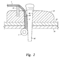
- FIG. 2 is a partial section view of a prior art anchoring arrangement. Visible in the Figure are a guitar top 25, a reinforcing member 30 below the top, a bridge 35 affixed to the top and an aperture 40 extending through the bridge, top and reinforcing member into an interior of the instrument.
- a string 1 is supported by a saddle 55 and has an enlarged diameter portion 2 terminating in a ball 3 on its end. The string is inserted through the aperture and held at a front side of the aperture by a pin 45.
- the section of the string extending through the aperture is housed in a vertical slot 50 formed in the bridge, top and reinforcing member in a manner whereby it conjoins the aperture.
- the slot is formed in the pin rather than in the aperture. In either case, the string 1 is held between the pin 45 and the aperture 40 and the pin must be precisely sized to fit in the aperture in a manner that retains the string while it is being tensioned and played.
- This conventional arrangement of the mounting hole, mounting pin, and saddle create geometry that can force the string into an undesirably small radius bend made worse by the stiffened end condition affected by the anchoring ball's retaining wrap.
- the radius of the string's bend over the saddle cannot be accomplished, leading to improper functioning of the instrument.
- the arrangement can cause the large diameter area of the string to contact the saddle, thereby preventing the string from "sounding" properly.
- the present invention generally includes a system for anchoring a guitar string comprising: a bridge pin insertable into an aperture formed in a top of a guitar, the pin having a larger diameter portion for retaining the pin on the guitar top and a body extendable into the aperture, the body having two spaced-apart legs forming a space therebetween wide enough to accommodate a string but not a ball mounted on an end of the string, a rear side of the legs having matching anchoring surfaces, the surfaces constructed and arranged to receive and retain the ball when the string is in tension.
- the system may comprise a guitar top.
- a bridge may be fixed to the guitar top.
- At least one aperture may extend through the bridge and top for receiving an end of a string, the end having a ball attached thereto.
- a said bridge pin may be insertable into a said aperture.
- the space between the two spaced apart legs of the bridge pin may be wide enough to accommodate the string but not the ball; and the anchoring surfaces on a rear side of the legs may be constructed and arranged to receive and retain the ball when the string is in tension.
- the present invention may generally include a system for anchoring a guitar string comprising a guitar top, a bridge fixed to the guitar top, and at least one aperture extending through the bridge and top for receiving an end of a string with a ball attached thereto.
- a bridge pin has a body that is insertable into the aperture. The body has two spaced-apart legs forming a space therebetween wide enough to accommodate the string but not the ball. A rear side of the legs has matching anchoring surfaces that are constructed and arranged to receive and retain the ball when the string is in tension.
- FIG 3 is a perspective view of a bridge pin 100 according to one aspect of the invention.
- the pin has a top portion 110 and an enlarged diameter portion 115 therebelow.
- the pin includes a body 120 having two legs 121, 122 that are separated to create a space 125 therebetween for accommodating a string as will be explained herein.
- the legs 121, 122 include an anchoring arrangement made up of matching anchoring surfaces 130a, 130b formed at a rear and inside surface of each leg 121, 122. The surfaces are designed to retain a ball end of a string as the string is tensioned and pulled against the surfaces.
- the surfaces 130a, 130b appear as a profile.
- Figures 3 and 5 illustrate the surfaces 130a, 130b as matching, angled surfaces formed in an inside, rear edge of each leg in a manner wherein they appear as a single tear drop shape best appreciated in Figure 5 .
- the angle 131 created by the surfaces is shown in Figure 6 , a section view taken along a line 6-6 of Figure 5 . In the embodiment of Figure 6 , angle 131 is about 45 degrees although the exact angle can vary based upon a number of factors including the size of the ball and the length of the pin legs that extend below the top of the instrument.
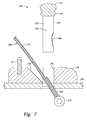
- FIG. 7 is a partial section view of an instrument showing the various portions of the anchoring system prior to installation of the pin 100 and tensioning of a string 200.
- a typical string is shown with a first diameter 210 and a larger diameter 220 portion having a cylindrical ball 225 attached at an end.
- Shown in section is an instrument top 140, a bridge 150 attached the top and a saddle 155 installed in the bridge.
- the saddle's purpose is to provide an end point for the string's vibration at the correct location for proper intonation and to transfer the vibrations through the bridge into the top wood of the guitar. For this reason it is necessary that the ball end of the string transitions to the smaller diameter 210 prior to contact with the bridge.
- An aperture 160 extends through the bridge and top and the string 200 is shown inserted through the aperture in a manner wherein the ball is housed in the body of the instrument. Rather than a vertical slot, the aperture includes an angled opening 161 in the form of a slot or notch in the direction of the saddle to reduce bending of the tensioned string as it moves from an interior of the instrument to the saddle 155.
- a pin 100 as described in reference to Figures 3-6 is shown above the aperture 160. While not shown in Figure 7 , an optional bridge reinforcement plate can be utilized in a way that sandwiches the top between the bridge and an additional piece of strong hardwood glued to the underside of the top.
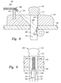
- Figure 8 is a partial section view of the anchoring system showing a string 200 prior to tensioning and Figure 9 is a rear view thereof.
- the string is shown inserted through the aperture 160 in the bridge and top and the pin is shown inserted in the aperture in a manner whereby the string runs along the angled portion 161 of the aperture and extends through space 125 formed between the legs 121, 122 of the pin 100.
- Anchoring surface 130b of the pin is visible and the ball 225 is shown adjacent that surface.
- Arrow 165 illustrates the direction of the string 200 as it is tightened from an opposite end and tension is applied.
- the ball is not in compression contact with the surfaces 130a, 130b of the pin legs and the legs have not been deformed due to forces between the pin and the ball.
- the tear drop shape of the surfaces serves as a guide to the ball 225 as the string 200 is initially tightened.
- Figure 10 is a partial section view of the anchoring system showing the string 200 retained after tensioning.
- Figure 11 is a rear view.
- the string 200 is shown in a tensioned condition and forces developed in the anchoring system are shown with arrows 168, 170, 172.
- the tensioning action has pulled the ball 225 into the pin 100 via surfaces 130a, 130b (130b visible in Figure 8 ).
- Those forces are shown with arrows 168, 170 and have also caused the ball to be firmly in contact with a lower surface 141 of top 140.
- the same forces serve to create a downward force (arrow 172) on the pin 100, thereby seating the enlarged diameter portion 115 of the pin firmly on the upper surface of the bridge 150.
- one embodiment of the anchoring system includes the following steps: A ball-end of a string is inserted through an aperture and into the body of an instrument, like a guitar.
- the aperture is formed in a bridge and top of the guitar and includes an angled slot.
- a pin like the one described herein is then inserted into the aperture in a manner whereby the string is straddled by two spaced-apart legs of the pin whereby the string enters the front of the pin and exists the rear of the pin.
- the string is tightened and put into tension and the ball is urged into contact with anchoring surfaces at the rear of the legs of the pin.
- the surfaces, along with an underside of the guitar top serve to anchor the ball end of the string in the instrument. In doing so, room is provided for the thickened end of the string prior to the string crossing a saddle.
- the slot in which the string passes through alleviates severely tight radius bends in the string, allowing a more relaxed end condition and the elimination of distortion of the string, critical to accurate musical function. Additionally, this arrangement provides clearance for the increased diameter of the doubly wrapped end of the string, and provides a more stable anchoring for the string overall which improves tuning stability of the complete instrument, enhanced clarity of the notes, and improves sustain of the string's vibration.
- the present invention utilizes a straight sided installation hole serving to anchor the string under the top and bridge at a point furthest from the saddle, with a space formed through the pin through which the string passes.
- the bridge features a clearance slot on the forward side of the hole.
- the bridge pin features a straight sided profile which mates to the straight sided, cylindrical hole.
Landscapes
- Physics & Mathematics (AREA)
- Engineering & Computer Science (AREA)
- Acoustics & Sound (AREA)
- Multimedia (AREA)
- Stringed Musical Instruments (AREA)
Abstract
Description
- The present invention relates to musical instruments. More particularly, the invention relates to stringed instruments, like guitars. More particularly still, the invention relates to an anchoring system for guitar strings.
-
Figure 1 is a plan view of a 6 string guitar showing thestrings 1 anchored at a first end at ahead stock 5 where they are tightened withtuners 10 and anchored at a second end at abridge 15 withbridge pins 20. Traditionally, the strings on fretted instruments are either single core wires or in the case of larger diameter strings, a core wire with another wire wrapped around it. In either case, a cylindrical "ball" is attached to one end of the string to facilitate anchoring the string to the instrument. The body of the string is secured to the anchoring ball by wrapping the string around the ball and back onto itself where it is twisted, thereby forming a loop which captures the cylindrical ball. This arrangement creates an extra stiff area near the end of the string with a larger diameter than the body of the string and the extra stiff area increases in length with the diameter of the string.Figure 2 is a partial section view of a prior art anchoring arrangement. Visible in the Figure are aguitar top 25, a reinforcingmember 30 below the top, abridge 35 affixed to the top and anaperture 40 extending through the bridge, top and reinforcing member into an interior of the instrument. Astring 1 is supported by asaddle 55 and has an enlargeddiameter portion 2 terminating in aball 3 on its end. The string is inserted through the aperture and held at a front side of the aperture by apin 45. In the example shown inFigure 2 , the section of the string extending through the aperture is housed in avertical slot 50 formed in the bridge, top and reinforcing member in a manner whereby it conjoins the aperture. In another example (not shown), the slot is formed in the pin rather than in the aperture. In either case, thestring 1 is held between thepin 45 and theaperture 40 and the pin must be precisely sized to fit in the aperture in a manner that retains the string while it is being tensioned and played. - This conventional arrangement of the mounting hole, mounting pin, and saddle, create geometry that can force the string into an undesirably small radius bend made worse by the stiffened end condition affected by the anchoring ball's retaining wrap. In extreme cases, when the string is of very large diameter, such as those found on a bass guitar, or in cases where the components of the bridge are exceptionally small or in close proximity, the radius of the string's bend over the saddle cannot be accomplished, leading to improper functioning of the instrument. Additionally, the arrangement can cause the large diameter area of the string to contact the saddle, thereby preventing the string from "sounding" properly. What is needed is an improved anchoring system for a string, in particular one that can be utilized in instances of large diameter strings and/or instruments having limited space for anchoring components.
- Aspects of the invention are set out in the independent claims. Certain preferred and optional features are set out in the dependent claims.
- The present invention generally includes a system for anchoring a guitar string comprising: a bridge pin insertable into an aperture formed in a top of a guitar, the pin having a larger diameter portion for retaining the pin on the guitar top and a body extendable into the aperture, the body having two spaced-apart legs forming a space therebetween wide enough to accommodate a string but not a ball mounted on an end of the string, a rear side of the legs having matching anchoring surfaces, the surfaces constructed and arranged to receive and retain the ball when the string is in tension.
- The system may comprise a guitar top. A bridge may be fixed to the guitar top. At least one aperture may extend through the bridge and top for receiving an end of a string, the end having a ball attached thereto. A said bridge pin may be insertable into a said aperture. The space between the two spaced apart legs of the bridge pin may be wide enough to accommodate the string but not the ball; and the anchoring surfaces on a rear side of the legs may be constructed and arranged to receive and retain the ball when the string is in tension.
- Accordingly, the present invention may generally include a system for anchoring a guitar string comprising a guitar top, a bridge fixed to the guitar top, and at least one aperture extending through the bridge and top for receiving an end of a string with a ball attached thereto. A bridge pin has a body that is insertable into the aperture. The body has two spaced-apart legs forming a space therebetween wide enough to accommodate the string but not the ball. A rear side of the legs has matching anchoring surfaces that are constructed and arranged to receive and retain the ball when the string is in tension.
- So that the manner in which the above recited features of the present invention can be understood in detail, a more particular description of the invention, briefly summarized above, may be had by reference to embodiments, some of which are illustrated in the appended drawings. It is to be noted, however, that the appended drawings illustrate only typical embodiments of this invention and are therefore not to be considered limiting of its scope, for the invention may admit to other equally effective embodiments.
-
Figure 1 is a plan view of a guitar. -
Figure 2 is a partial section view of a prior art mounting arrangement. -
Figure 3 is a perspective view of a bridge pin according to one aspect of the invention. -
Figure 4 is a side view of the pin ofFigure 3 . -
Figure 5 is a rear view of the pin illustrating anchoring surfaces formed in the legs of the pin. -
Figure 6 is a section view taken along a line 6-6 ofFigure 5 . -
Figure 7 is a partial section view of an instrument showing a top, bridge, saddle, pin and a string extending through an aperture in the bridge and top. -
Figure 8 is a partial section view showing a string prior to tensioning andFigure 9 is a rear view thereof. -
Figure 10 is a partial section view showing the string retained after tensioning andFigure 11 is a rear view thereof. -
Figure 3 is a perspective view of abridge pin 100 according to one aspect of the invention. In the embodiment shown the pin has atop portion 110 and an enlargeddiameter portion 115 therebelow. The pin includes abody 120 having twolegs space 125 therebetween for accommodating a string as will be explained herein. ConsideringFigures 3-6 together, thelegs anchoring surfaces leg Figure 4 thesurfaces Figures 3 and 5 illustrate thesurfaces Figure 5 . Theangle 131 created by the surfaces is shown inFigure 6 , a section view taken along a line 6-6 ofFigure 5 . In the embodiment ofFigure 6 ,angle 131 is about 45 degrees although the exact angle can vary based upon a number of factors including the size of the ball and the length of the pin legs that extend below the top of the instrument. -
Figure 7 is a partial section view of an instrument showing the various portions of the anchoring system prior to installation of thepin 100 and tensioning of astring 200. A typical string is shown with afirst diameter 210 and alarger diameter 220 portion having acylindrical ball 225 attached at an end. Shown in section is aninstrument top 140, abridge 150 attached the top and asaddle 155 installed in the bridge. The saddle's purpose is to provide an end point for the string's vibration at the correct location for proper intonation and to transfer the vibrations through the bridge into the top wood of the guitar. For this reason it is necessary that the ball end of the string transitions to thesmaller diameter 210 prior to contact with the bridge. Anaperture 160 extends through the bridge and top and thestring 200 is shown inserted through the aperture in a manner wherein the ball is housed in the body of the instrument. Rather than a vertical slot, the aperture includes anangled opening 161 in the form of a slot or notch in the direction of the saddle to reduce bending of the tensioned string as it moves from an interior of the instrument to thesaddle 155. Apin 100 as described in reference toFigures 3-6 is shown above theaperture 160. While not shown inFigure 7 , an optional bridge reinforcement plate can be utilized in a way that sandwiches the top between the bridge and an additional piece of strong hardwood glued to the underside of the top. -
Figure 8 is a partial section view of the anchoring system showing astring 200 prior to tensioning andFigure 9 is a rear view thereof. The string is shown inserted through theaperture 160 in the bridge and top and the pin is shown inserted in the aperture in a manner whereby the string runs along theangled portion 161 of the aperture and extends throughspace 125 formed between thelegs pin 100. Anchoringsurface 130b of the pin is visible and theball 225 is shown adjacent that surface.Arrow 165 illustrates the direction of thestring 200 as it is tightened from an opposite end and tension is applied. InFigures 8 and 9 the ball is not in compression contact with thesurfaces ball 225 as thestring 200 is initially tightened. -
Figure 10 is a partial section view of the anchoring system showing thestring 200 retained after tensioning.Figure 11 is a rear view. Thestring 200 is shown in a tensioned condition and forces developed in the anchoring system are shown witharrows ball 225 into thepin 100 viasurfaces Figure 8 ). Those forces are shown witharrows top 140. The same forces serve to create a downward force (arrow 172) on thepin 100, thereby seating theenlarged diameter portion 115 of the pin firmly on the upper surface of thebridge 150. ConsideringFigure 11 , the force between the ball and the anchoring surfaces of the pin has deformed the legs in the area of the ball and surfaces and enlarged the space between the legs as shown bydistance 175. In this manner, the pin, and with it the string is further anchored in the aperture. - In operation, one embodiment of the anchoring system includes the following steps: A ball-end of a string is inserted through an aperture and into the body of an instrument, like a guitar. Typically, the aperture is formed in a bridge and top of the guitar and includes an angled slot. A pin like the one described herein is then inserted into the aperture in a manner whereby the string is straddled by two spaced-apart legs of the pin whereby the string enters the front of the pin and exists the rear of the pin. Thereafter, the string is tightened and put into tension and the ball is urged into contact with anchoring surfaces at the rear of the legs of the pin. The surfaces, along with an underside of the guitar top, serve to anchor the ball end of the string in the instrument. In doing so, room is provided for the thickened end of the string prior to the string crossing a saddle.
- While simultaneously anchoring the string, the slot in which the string passes through alleviates severely tight radius bends in the string, allowing a more relaxed end condition and the elimination of distortion of the string, critical to accurate musical function. Additionally, this arrangement provides clearance for the increased diameter of the doubly wrapped end of the string, and provides a more stable anchoring for the string overall which improves tuning stability of the complete instrument, enhanced clarity of the notes, and improves sustain of the string's vibration.
- Unlike conventional string mounting, the present invention utilizes a straight sided installation hole serving to anchor the string under the top and bridge at a point furthest from the saddle, with a space formed through the pin through which the string passes. The bridge features a clearance slot on the forward side of the hole. The bridge pin features a straight sided profile which mates to the straight sided, cylindrical hole. By utilizing a straight sided pin and matching straight sided bore, as well as a clearance ramp located entirely in the bridge, accurate manufacturing is greatly facilitated.
- While the foregoing is directed to embodiments of the present invention, other and further embodiments of the invention may be devised without departing from the basic scope thereof, and the scope thereof is determined by the claims that follow. For example, the invention as described presumes a bridge on an instrument top and an aperture that extends through both the bridge and top. It will be understood that these components can be combined or the invention can be used without a bridge. While the invention might typically be used with a 6 string guitar it is equally useful with a base guitar having fewer strings of a mandolin, 12 string guitar or any stringed instrument utilizing a ball that requires anchoring at one end.
Claims (13)
guide the ball (225) into the pin (100); and/or
urge the pin downwards into the aperture (160).
Applications Claiming Priority (1)
| Application Number | Priority Date | Filing Date | Title |
|---|---|---|---|
| US14/086,839 US9355622B2 (en) | 2013-11-21 | 2013-11-21 | Anchoring system for a string in a musical instrument |
Publications (3)
| Publication Number | Publication Date |
|---|---|
| EP2876637A2 true EP2876637A2 (en) | 2015-05-27 |
| EP2876637A3 EP2876637A3 (en) | 2016-01-20 |
| EP2876637B1 EP2876637B1 (en) | 2018-04-25 |
Family
ID=51846473
Family Applications (1)
| Application Number | Title | Priority Date | Filing Date |
|---|---|---|---|
| EP14190262.7A Active EP2876637B1 (en) | 2013-11-21 | 2014-10-24 | Anchoring system for a string in a musical instrument |
Country Status (2)
| Country | Link |
|---|---|
| US (1) | US9355622B2 (en) |
| EP (1) | EP2876637B1 (en) |
Families Citing this family (1)
| Publication number | Priority date | Publication date | Assignee | Title |
|---|---|---|---|---|
| US10937395B2 (en) * | 2016-07-25 | 2021-03-02 | Robert L. Oberg | Saddle for a stringed musical instrument |
Family Cites Families (7)
| Publication number | Priority date | Publication date | Assignee | Title |
|---|---|---|---|---|
| US4202240A (en) * | 1978-07-13 | 1980-05-13 | Smith Gerald E | Bridge pin |
| US4197779A (en) * | 1979-03-08 | 1980-04-15 | Holman Mitchell R | High density bridge pin |
| US5477764A (en) | 1993-07-01 | 1995-12-26 | Carrico; Eugene N. | Quick attachment mechanism for guitar strings |
| JP2000267668A (en) * | 1999-03-18 | 2000-09-29 | Hoshino Gakki Kk | Bridge mechanism of guitar |
| US7112733B1 (en) * | 2003-07-30 | 2006-09-26 | Babicz Jeffrey T | String instrument |
| US7154032B2 (en) * | 2004-07-28 | 2006-12-26 | Burchfield Charles C | String attachment system apparatus and method for a stringed musical instrument |
| US7394005B1 (en) * | 2007-04-30 | 2008-07-01 | Richard Anderson | Anchor for musical instrument strings and method for installing the anchor |
-
2013
- 2013-11-21 US US14/086,839 patent/US9355622B2/en active Active
-
2014
- 2014-10-24 EP EP14190262.7A patent/EP2876637B1/en active Active
Non-Patent Citations (1)
| Title |
|---|
| None |
Also Published As
| Publication number | Publication date |
|---|---|
| US20150135929A1 (en) | 2015-05-21 |
| US9355622B2 (en) | 2016-05-31 |
| EP2876637B1 (en) | 2018-04-25 |
| EP2876637A3 (en) | 2016-01-20 |
Similar Documents
| Publication | Publication Date | Title |
|---|---|---|
| US20040134329A1 (en) | Variable configuration guitar bridge | |
| US9018501B2 (en) | String locking structure for electric guitar and tailpiece | |
| US6982372B2 (en) | Acoustic musical instrument and method | |
| US7893329B2 (en) | Chin-rest for a violin | |
| CN109300450A (en) | Stringed instrument for producing sound from two soundboards on opposite sides of the instrument and method of construction | |
| EP2876637B1 (en) | Anchoring system for a string in a musical instrument | |
| US20170011719A1 (en) | Recessed concave fingerboard | |
| US7759567B2 (en) | Single vertex damped cable tailpiece for bowed string instruments | |
| US9324308B1 (en) | Guitar string bender | |
| US9190032B2 (en) | Guitar string tuning and anchor system | |
| US7098391B2 (en) | Protective sleeve for an instrument string and its method of application to an instrument | |
| US7154032B2 (en) | String attachment system apparatus and method for a stringed musical instrument | |
| US20020104428A1 (en) | Protective sleeve for an instrument string and its method of application to an instrument | |
| US11798519B1 (en) | Acoustic guitar string mounting system and method | |
| EP3438966A1 (en) | Guitar fingerboard | |
| US5753837A (en) | Adjustable reinforced neck assembly for stringed musical instrument | |
| US20140165817A1 (en) | Lock For Tremolo Bridge | |
| US20060016317A1 (en) | String tuning device | |
| US7358429B2 (en) | Magnetized frets for a stringed musical instrument | |
| US7351894B2 (en) | Guitar string retainer guide | |
| US12315477B2 (en) | String tool for replacing strings on instruments and method of using | |
| JP2005148099A (en) | String support structure for stringed instrument | |
| US10621958B2 (en) | Stop bar for a stringed musical instrument | |
| US11600247B2 (en) | Musical instrument string ferrule tubes | |
| JP3166970U (en) | Guitar bridge pin |
Legal Events
| Date | Code | Title | Description |
|---|---|---|---|
| PUAI | Public reference made under article 153(3) epc to a published international application that has entered the european phase |
Free format text: ORIGINAL CODE: 0009012 |
|
| 17P | Request for examination filed |
Effective date: 20141024 |
|
| AK | Designated contracting states |
Kind code of ref document: A2 Designated state(s): AL AT BE BG CH CY CZ DE DK EE ES FI FR GB GR HR HU IE IS IT LI LT LU LV MC MK MT NL NO PL PT RO RS SE SI SK SM TR |
|
| AX | Request for extension of the european patent |
Extension state: BA ME |
|
| PUAL | Search report despatched |
Free format text: ORIGINAL CODE: 0009013 |
|
| AK | Designated contracting states |
Kind code of ref document: A3 Designated state(s): AL AT BE BG CH CY CZ DE DK EE ES FI FR GB GR HR HU IE IS IT LI LT LU LV MC MK MT NL NO PL PT RO RS SE SI SK SM TR |
|
| AX | Request for extension of the european patent |
Extension state: BA ME |
|
| RIC1 | Information provided on ipc code assigned before grant |
Ipc: G10D 3/12 20060101AFI20151216BHEP |
|
| R17P | Request for examination filed (corrected) |
Effective date: 20160719 |
|
| RBV | Designated contracting states (corrected) |
Designated state(s): AL AT BE BG CH CY CZ DE DK EE ES FI FR GB GR HR HU IE IS IT LI LT LU LV MC MK MT NL NO PL PT RO RS SE SI SK SM TR |
|
| GRAP | Despatch of communication of intention to grant a patent |
Free format text: ORIGINAL CODE: EPIDOSNIGR1 |
|
| RAP1 | Party data changed (applicant data changed or rights of an application transferred) |
Owner name: TAYLOR-LISTUG, INC. D/B/A TAYLOR GUITARS |
|
| INTG | Intention to grant announced |
Effective date: 20180206 |
|
| GRAA | (expected) grant |
Free format text: ORIGINAL CODE: 0009210 |
|
| GRAS | Grant fee paid |
Free format text: ORIGINAL CODE: EPIDOSNIGR3 |
|
| AK | Designated contracting states |
Kind code of ref document: B1 Designated state(s): AL AT BE BG CH CY CZ DE DK EE ES FI FR GB GR HR HU IE IS IT LI LT LU LV MC MK MT NL NO PL PT RO RS SE SI SK SM TR |
|
| REG | Reference to a national code |
Ref country code: GB Ref legal event code: FG4D |
|
| REG | Reference to a national code |
Ref country code: CH Ref legal event code: EP |
|
| REG | Reference to a national code |
Ref country code: AT Ref legal event code: REF Ref document number: 993693 Country of ref document: AT Kind code of ref document: T Effective date: 20180515 |
|
| REG | Reference to a national code |
Ref country code: IE Ref legal event code: FG4D |
|
| REG | Reference to a national code |
Ref country code: DE Ref legal event code: R096 Ref document number: 602014024346 Country of ref document: DE |
|
| REG | Reference to a national code |
Ref country code: NL Ref legal event code: FP |
|
| REG | Reference to a national code |
Ref country code: LT Ref legal event code: MG4D |
|
| REG | Reference to a national code |
Ref country code: FR Ref legal event code: PLFP Year of fee payment: 5 |
|
| PG25 | Lapsed in a contracting state [announced via postgrant information from national office to epo] |
Ref country code: FI Free format text: LAPSE BECAUSE OF FAILURE TO SUBMIT A TRANSLATION OF THE DESCRIPTION OR TO PAY THE FEE WITHIN THE PRESCRIBED TIME-LIMIT Effective date: 20180425 Ref country code: BG Free format text: LAPSE BECAUSE OF FAILURE TO SUBMIT A TRANSLATION OF THE DESCRIPTION OR TO PAY THE FEE WITHIN THE PRESCRIBED TIME-LIMIT Effective date: 20180725 Ref country code: LT Free format text: LAPSE BECAUSE OF FAILURE TO SUBMIT A TRANSLATION OF THE DESCRIPTION OR TO PAY THE FEE WITHIN THE PRESCRIBED TIME-LIMIT Effective date: 20180425 Ref country code: PL Free format text: LAPSE BECAUSE OF FAILURE TO SUBMIT A TRANSLATION OF THE DESCRIPTION OR TO PAY THE FEE WITHIN THE PRESCRIBED TIME-LIMIT Effective date: 20180425 Ref country code: SE Free format text: LAPSE BECAUSE OF FAILURE TO SUBMIT A TRANSLATION OF THE DESCRIPTION OR TO PAY THE FEE WITHIN THE PRESCRIBED TIME-LIMIT Effective date: 20180425 Ref country code: NO Free format text: LAPSE BECAUSE OF FAILURE TO SUBMIT A TRANSLATION OF THE DESCRIPTION OR TO PAY THE FEE WITHIN THE PRESCRIBED TIME-LIMIT Effective date: 20180725 Ref country code: ES Free format text: LAPSE BECAUSE OF FAILURE TO SUBMIT A TRANSLATION OF THE DESCRIPTION OR TO PAY THE FEE WITHIN THE PRESCRIBED TIME-LIMIT Effective date: 20180425 |
|
| PG25 | Lapsed in a contracting state [announced via postgrant information from national office to epo] |
Ref country code: GR Free format text: LAPSE BECAUSE OF FAILURE TO SUBMIT A TRANSLATION OF THE DESCRIPTION OR TO PAY THE FEE WITHIN THE PRESCRIBED TIME-LIMIT Effective date: 20180726 Ref country code: LV Free format text: LAPSE BECAUSE OF FAILURE TO SUBMIT A TRANSLATION OF THE DESCRIPTION OR TO PAY THE FEE WITHIN THE PRESCRIBED TIME-LIMIT Effective date: 20180425 Ref country code: HR Free format text: LAPSE BECAUSE OF FAILURE TO SUBMIT A TRANSLATION OF THE DESCRIPTION OR TO PAY THE FEE WITHIN THE PRESCRIBED TIME-LIMIT Effective date: 20180425 Ref country code: RS Free format text: LAPSE BECAUSE OF FAILURE TO SUBMIT A TRANSLATION OF THE DESCRIPTION OR TO PAY THE FEE WITHIN THE PRESCRIBED TIME-LIMIT Effective date: 20180425 |
|
| REG | Reference to a national code |
Ref country code: AT Ref legal event code: MK05 Ref document number: 993693 Country of ref document: AT Kind code of ref document: T Effective date: 20180425 |
|
| PG25 | Lapsed in a contracting state [announced via postgrant information from national office to epo] |
Ref country code: PT Free format text: LAPSE BECAUSE OF FAILURE TO SUBMIT A TRANSLATION OF THE DESCRIPTION OR TO PAY THE FEE WITHIN THE PRESCRIBED TIME-LIMIT Effective date: 20180827 |
|
| REG | Reference to a national code |
Ref country code: DE Ref legal event code: R097 Ref document number: 602014024346 Country of ref document: DE |
|
| PG25 | Lapsed in a contracting state [announced via postgrant information from national office to epo] |
Ref country code: SK Free format text: LAPSE BECAUSE OF FAILURE TO SUBMIT A TRANSLATION OF THE DESCRIPTION OR TO PAY THE FEE WITHIN THE PRESCRIBED TIME-LIMIT Effective date: 20180425 Ref country code: EE Free format text: LAPSE BECAUSE OF FAILURE TO SUBMIT A TRANSLATION OF THE DESCRIPTION OR TO PAY THE FEE WITHIN THE PRESCRIBED TIME-LIMIT Effective date: 20180425 Ref country code: CZ Free format text: LAPSE BECAUSE OF FAILURE TO SUBMIT A TRANSLATION OF THE DESCRIPTION OR TO PAY THE FEE WITHIN THE PRESCRIBED TIME-LIMIT Effective date: 20180425 Ref country code: RO Free format text: LAPSE BECAUSE OF FAILURE TO SUBMIT A TRANSLATION OF THE DESCRIPTION OR TO PAY THE FEE WITHIN THE PRESCRIBED TIME-LIMIT Effective date: 20180425 Ref country code: DK Free format text: LAPSE BECAUSE OF FAILURE TO SUBMIT A TRANSLATION OF THE DESCRIPTION OR TO PAY THE FEE WITHIN THE PRESCRIBED TIME-LIMIT Effective date: 20180425 Ref country code: AT Free format text: LAPSE BECAUSE OF FAILURE TO SUBMIT A TRANSLATION OF THE DESCRIPTION OR TO PAY THE FEE WITHIN THE PRESCRIBED TIME-LIMIT Effective date: 20180425 |
|
| PG25 | Lapsed in a contracting state [announced via postgrant information from national office to epo] |
Ref country code: SM Free format text: LAPSE BECAUSE OF FAILURE TO SUBMIT A TRANSLATION OF THE DESCRIPTION OR TO PAY THE FEE WITHIN THE PRESCRIBED TIME-LIMIT Effective date: 20180425 |
|
| PLBE | No opposition filed within time limit |
Free format text: ORIGINAL CODE: 0009261 |
|
| STAA | Information on the status of an ep patent application or granted ep patent |
Free format text: STATUS: NO OPPOSITION FILED WITHIN TIME LIMIT |
|
| 26N | No opposition filed |
Effective date: 20190128 |
|
| PG25 | Lapsed in a contracting state [announced via postgrant information from national office to epo] |
Ref country code: SI Free format text: LAPSE BECAUSE OF FAILURE TO SUBMIT A TRANSLATION OF THE DESCRIPTION OR TO PAY THE FEE WITHIN THE PRESCRIBED TIME-LIMIT Effective date: 20180425 |
|
| REG | Reference to a national code |
Ref country code: CH Ref legal event code: PL |
|
| REG | Reference to a national code |
Ref country code: BE Ref legal event code: MM Effective date: 20181031 |
|
| PG25 | Lapsed in a contracting state [announced via postgrant information from national office to epo] |
Ref country code: LU Free format text: LAPSE BECAUSE OF NON-PAYMENT OF DUE FEES Effective date: 20181024 Ref country code: MC Free format text: LAPSE BECAUSE OF FAILURE TO SUBMIT A TRANSLATION OF THE DESCRIPTION OR TO PAY THE FEE WITHIN THE PRESCRIBED TIME-LIMIT Effective date: 20180425 |
|
| REG | Reference to a national code |
Ref country code: IE Ref legal event code: MM4A |
|
| PG25 | Lapsed in a contracting state [announced via postgrant information from national office to epo] |
Ref country code: BE Free format text: LAPSE BECAUSE OF NON-PAYMENT OF DUE FEES Effective date: 20181031 Ref country code: LI Free format text: LAPSE BECAUSE OF NON-PAYMENT OF DUE FEES Effective date: 20181031 Ref country code: CH Free format text: LAPSE BECAUSE OF NON-PAYMENT OF DUE FEES Effective date: 20181031 |
|
| PG25 | Lapsed in a contracting state [announced via postgrant information from national office to epo] |
Ref country code: IE Free format text: LAPSE BECAUSE OF NON-PAYMENT OF DUE FEES Effective date: 20181024 |
|
| PG25 | Lapsed in a contracting state [announced via postgrant information from national office to epo] |
Ref country code: AL Free format text: LAPSE BECAUSE OF FAILURE TO SUBMIT A TRANSLATION OF THE DESCRIPTION OR TO PAY THE FEE WITHIN THE PRESCRIBED TIME-LIMIT Effective date: 20180425 |
|
| PG25 | Lapsed in a contracting state [announced via postgrant information from national office to epo] |
Ref country code: MT Free format text: LAPSE BECAUSE OF NON-PAYMENT OF DUE FEES Effective date: 20181024 |
|
| PG25 | Lapsed in a contracting state [announced via postgrant information from national office to epo] |
Ref country code: TR Free format text: LAPSE BECAUSE OF FAILURE TO SUBMIT A TRANSLATION OF THE DESCRIPTION OR TO PAY THE FEE WITHIN THE PRESCRIBED TIME-LIMIT Effective date: 20180425 |
|
| PG25 | Lapsed in a contracting state [announced via postgrant information from national office to epo] |
Ref country code: CY Free format text: LAPSE BECAUSE OF FAILURE TO SUBMIT A TRANSLATION OF THE DESCRIPTION OR TO PAY THE FEE WITHIN THE PRESCRIBED TIME-LIMIT Effective date: 20180425 Ref country code: MK Free format text: LAPSE BECAUSE OF NON-PAYMENT OF DUE FEES Effective date: 20180425 Ref country code: HU Free format text: LAPSE BECAUSE OF FAILURE TO SUBMIT A TRANSLATION OF THE DESCRIPTION OR TO PAY THE FEE WITHIN THE PRESCRIBED TIME-LIMIT; INVALID AB INITIO Effective date: 20141024 |
|
| PG25 | Lapsed in a contracting state [announced via postgrant information from national office to epo] |
Ref country code: IS Free format text: LAPSE BECAUSE OF FAILURE TO SUBMIT A TRANSLATION OF THE DESCRIPTION OR TO PAY THE FEE WITHIN THE PRESCRIBED TIME-LIMIT Effective date: 20180825 |
|
| PGFP | Annual fee paid to national office [announced via postgrant information from national office to epo] |
Ref country code: NL Payment date: 20250916 Year of fee payment: 12 |
|
| PGFP | Annual fee paid to national office [announced via postgrant information from national office to epo] |
Ref country code: GB Payment date: 20250911 Year of fee payment: 12 |
|
| PGFP | Annual fee paid to national office [announced via postgrant information from national office to epo] |
Ref country code: FR Payment date: 20250912 Year of fee payment: 12 |
|
| PGFP | Annual fee paid to national office [announced via postgrant information from national office to epo] |
Ref country code: DE Payment date: 20250912 Year of fee payment: 12 |
|
| PGFP | Annual fee paid to national office [announced via postgrant information from national office to epo] |
Ref country code: IT Payment date: 20251013 Year of fee payment: 12 |