EP2876535A1 - Display input apparatus, image forming apparatus having the same, and method for controlling the display input apparatus - Google Patents
Display input apparatus, image forming apparatus having the same, and method for controlling the display input apparatus Download PDFInfo
- Publication number
- EP2876535A1 EP2876535A1 EP14192778.0A EP14192778A EP2876535A1 EP 2876535 A1 EP2876535 A1 EP 2876535A1 EP 14192778 A EP14192778 A EP 14192778A EP 2876535 A1 EP2876535 A1 EP 2876535A1
- Authority
- EP
- European Patent Office
- Prior art keywords
- numerical value
- input
- reference line
- display
- predetermined region
- Prior art date
- Legal status (The legal status is an assumption and is not a legal conclusion. Google has not performed a legal analysis and makes no representation as to the accuracy of the status listed.)
- Granted
Links
Images




Classifications
-
- H—ELECTRICITY
- H04—ELECTRIC COMMUNICATION TECHNIQUE
- H04N—PICTORIAL COMMUNICATION, e.g. TELEVISION
- H04N1/00—Scanning, transmission or reproduction of documents or the like, e.g. facsimile transmission; Details thereof
- H04N1/0035—User-machine interface; Control console
- H04N1/00352—Input means
- H04N1/00395—Arrangements for reducing operator input
-
- G—PHYSICS
- G06—COMPUTING OR CALCULATING; COUNTING
- G06F—ELECTRIC DIGITAL DATA PROCESSING
- G06F3/00—Input arrangements for transferring data to be processed into a form capable of being handled by the computer; Output arrangements for transferring data from processing unit to output unit, e.g. interface arrangements
- G06F3/01—Input arrangements or combined input and output arrangements for interaction between user and computer
- G06F3/048—Interaction techniques based on graphical user interfaces [GUI]
- G06F3/0484—Interaction techniques based on graphical user interfaces [GUI] for the control of specific functions or operations, e.g. selecting or manipulating an object, an image or a displayed text element, setting a parameter value or selecting a range
- G06F3/04847—Interaction techniques to control parameter settings, e.g. interaction with sliders or dials
-
- G—PHYSICS
- G06—COMPUTING OR CALCULATING; COUNTING
- G06F—ELECTRIC DIGITAL DATA PROCESSING
- G06F3/00—Input arrangements for transferring data to be processed into a form capable of being handled by the computer; Output arrangements for transferring data from processing unit to output unit, e.g. interface arrangements
- G06F3/01—Input arrangements or combined input and output arrangements for interaction between user and computer
- G06F3/048—Interaction techniques based on graphical user interfaces [GUI]
- G06F3/0487—Interaction techniques based on graphical user interfaces [GUI] using specific features provided by the input device, e.g. functions controlled by the rotation of a mouse with dual sensing arrangements, or of the nature of the input device, e.g. tap gestures based on pressure sensed by a digitiser
- G06F3/0488—Interaction techniques based on graphical user interfaces [GUI] using specific features provided by the input device, e.g. functions controlled by the rotation of a mouse with dual sensing arrangements, or of the nature of the input device, e.g. tap gestures based on pressure sensed by a digitiser using a touch-screen or digitiser, e.g. input of commands through traced gestures
- G06F3/04883—Interaction techniques based on graphical user interfaces [GUI] using specific features provided by the input device, e.g. functions controlled by the rotation of a mouse with dual sensing arrangements, or of the nature of the input device, e.g. tap gestures based on pressure sensed by a digitiser using a touch-screen or digitiser, e.g. input of commands through traced gestures for inputting data by handwriting, e.g. gesture or text
-
- G—PHYSICS
- G06—COMPUTING OR CALCULATING; COUNTING
- G06F—ELECTRIC DIGITAL DATA PROCESSING
- G06F3/00—Input arrangements for transferring data to be processed into a form capable of being handled by the computer; Output arrangements for transferring data from processing unit to output unit, e.g. interface arrangements
- G06F3/01—Input arrangements or combined input and output arrangements for interaction between user and computer
- G06F3/048—Interaction techniques based on graphical user interfaces [GUI]
- G06F3/0487—Interaction techniques based on graphical user interfaces [GUI] using specific features provided by the input device, e.g. functions controlled by the rotation of a mouse with dual sensing arrangements, or of the nature of the input device, e.g. tap gestures based on pressure sensed by a digitiser
- G06F3/0488—Interaction techniques based on graphical user interfaces [GUI] using specific features provided by the input device, e.g. functions controlled by the rotation of a mouse with dual sensing arrangements, or of the nature of the input device, e.g. tap gestures based on pressure sensed by a digitiser using a touch-screen or digitiser, e.g. input of commands through traced gestures
- G06F3/04886—Interaction techniques based on graphical user interfaces [GUI] using specific features provided by the input device, e.g. functions controlled by the rotation of a mouse with dual sensing arrangements, or of the nature of the input device, e.g. tap gestures based on pressure sensed by a digitiser using a touch-screen or digitiser, e.g. input of commands through traced gestures by partitioning the display area of the touch-screen or the surface of the digitising tablet into independently controllable areas, e.g. virtual keyboards or menus
-
- H—ELECTRICITY
- H04—ELECTRIC COMMUNICATION TECHNIQUE
- H04N—PICTORIAL COMMUNICATION, e.g. TELEVISION
- H04N1/00—Scanning, transmission or reproduction of documents or the like, e.g. facsimile transmission; Details thereof
- H04N1/0035—User-machine interface; Control console
- H04N1/00352—Input means
- H04N1/00392—Other manual input means, e.g. digitisers or writing tablets
-
- H—ELECTRICITY
- H04—ELECTRIC COMMUNICATION TECHNIQUE
- H04N—PICTORIAL COMMUNICATION, e.g. TELEVISION
- H04N1/00—Scanning, transmission or reproduction of documents or the like, e.g. facsimile transmission; Details thereof
- H04N1/0035—User-machine interface; Control console
- H04N1/00405—Output means
- H04N1/00408—Display of information to the user, e.g. menus
- H04N1/00411—Display of information to the user, e.g. menus the display also being used for user input, e.g. touch screen
-
- H—ELECTRICITY
- H04—ELECTRIC COMMUNICATION TECHNIQUE
- H04N—PICTORIAL COMMUNICATION, e.g. TELEVISION
- H04N1/00—Scanning, transmission or reproduction of documents or the like, e.g. facsimile transmission; Details thereof
- H04N1/0035—User-machine interface; Control console
- H04N1/00405—Output means
- H04N1/00482—Output means outputting a plurality of job set-up options, e.g. number of copies, paper size or resolution
-
- H—ELECTRICITY
- H04—ELECTRIC COMMUNICATION TECHNIQUE
- H04N—PICTORIAL COMMUNICATION, e.g. TELEVISION
- H04N2201/00—Indexing scheme relating to scanning, transmission or reproduction of documents or the like, and to details thereof
- H04N2201/0077—Types of the still picture apparatus
- H04N2201/0094—Multifunctional device, i.e. a device capable of all of reading, reproducing, copying, facsimile transception, file transception
Definitions
- the present disclosure relates to a display input apparatus, an image forming apparatus including the same, and a method for controlling the display input apparatus.
- a display input apparatus a display apparatus with a touch panel which is installed in image forming apparatuses such as a multi-functional machine and the like, and is called an operation panel, for example.
- an operation panel accepts operations for setting and changing set values for various kinds of setting items relevant to operation of an image forming apparatus.
- a numerical value input becomes necessary when setting and changing the number of copies and a copy magnification. Accordingly, conventionally, when accepting a numerical value input, a numeric key pad is displayed as a software key on an operation panel. In this way, it is possible to input a desired numerical value by operating the numeric key pad (software key).
- the operation panel that displays the numeric key pad (software key) to accept a numerical value input, for example, upon performing a tap operation (operation like tapping with a finger) on any one of numerical value keys of "0" to "9," a numerical value corresponding to the tapped numerical value key is input.
- a tap operation operation like tapping with a finger
- a numerical value corresponding to the tapped numerical value key is input.
- this structure in a case of inputting a two- or more-digit numerical value, it is necessary to perform the tap operation on numerical value keys two times or more. Accordingly, it is onerous and inconvenient for a user.
- an operation panel which displays a numerical value increase/decrease key (software key) including a plus key and a minus key when accepting a numerical value input.
- a numerical value increase/decrease key software key
- an input numerical value increases 1
- an input numerical value decreases 1.
- it is necessary to perform the tap operation on the numerical value increase/decrease key many times until an input numerical value becomes a desired value. Further, it takes a long time until the input numerical value becomes the desired value.
- a display input apparatus includes a display portion, a touch panel portion, and a control portion.
- the display portion displays an input numerical value input screen for accepting an input of a numerical value and displays an input numerical value, namely, a numerical value that is input, in the numerical value input screen.
- the touch panel portion is disposed correspondingly to the display portion and accepts a predetermined region dividing operation on a screen of the display portion.
- the control portion detects, based on an output from the touch panel portion, the touch operation accepted by the touch panel portion.
- the control portion sets a line, which passes through a predetermined position of the predetermined region in the second direction, as a first reference line; sets an end edge, which is opposite to the first reference line of the predetermined region in the first direction, as a second reference line; obtains a ratio for input numerical value calculation that is a ratio of a distance from the first reference line to the second reference line and a distance from the first reference line to a division line of the predetermined region that is divided by the region dividing operation; and obtains a numerical value, which is obtained by multiplying a maximum value or minimum value in a numerical value input range of the numerical value input screen by the ratio for input numerical value calculation, as the input numerical value.
- the display portion displays the input numerical value, which is obtained by the control portion, in the numerical value input screen.
- An image forming apparatus includes the above display input apparatus.
- a method for controlling a display input apparatus is a method for controlling a display input apparatus that includes: a display portion which displays a numerical value input screen for accepting an input of a numerical value and displays an input numerical value, namely, a numerical value that is input, in the numerical value input screen; and a touch panel portion which is disposed correspondingly to the display portion and accepts a touch operation on a screen of the display portion, the method comprising: a step in which when the touch panel portion accepts a predetermined region dividing operation as a touch operation that divides a predetermined region in the numerical value input screen along a second direction which meets a first direction at right tangles, a line, which passes through a predetermined position of the predetermined region in the second direction, is set as a first reference line, an end edge opposite, in the first direction, to the first reference line of the predetermined region is set as a second reference line, whereby a ratio for input numerical value calculation is obtained, which is, namely, a
- a multi-functional machine which can execute various kinds of jobs such as a copy job, a print job, a transmission job and the like.
- a multi-functional machine 100 (which corresponds to an "image forming apparatus") includes an image reading portion 1 and a printing portion 2.
- the image reading portion 1 reads a document to generate image data.
- the image data obtained by reading of the image forming portion 1 is transmittable to an external apparatus (transmission job).
- the printing portion 2 prints an image based on image data onto a paper sheet P and outputs the paper sheet.
- the printing portion 2 prints an image, which is based on image data obtained by the image reading portion 1 reading a document, onto the paper sheet P and outputs the paper sheet (copy job).
- the printing portion 2 prints an image, which is based on image data transmitted from an external apparatus, onto the paper sheet P and outputs the paper sheet (print job).
- the printing portion 2 is composed of a paper sheet feeding portion 3, a paper sheet conveying portion 4, an image forming portion 5, and a fixing portion 6.
- the paper sheet feeding portion 3 includes a pickup roller 31 and a pair of paper sheet feeding rollers 32, and supplies the paper sheet P housed in a paper sheet cassette 33 to a paper sheet conveying path 20.
- the paper sheet conveying portion 4 includes a plurality of pairs of conveying rollers 41, conveys the paper sheet P along the paper sheet conveying path 20, and delivers the printed paper sheet P onto a delivery tray 42.
- the image forming portion 5 includes a photosensitive drum 51, a charging device 52, an exposure device 53, a developing device 54, a transfer roller 55, and a cleaning device 56. And, the image forming portion 5 forms a toner image based on image data, and transfers the toner image to the paper sheet P.
- the fixing portion 6 includes a heat roller 61 and a pressure roller 62, heats and pressures the toner image transferred to the paper sheet P to fix the toner image.
- the multi-functional machine 100 includes an operational panel 8 shown in Fig. 2 .
- the operation panel 8 is disposed on a front side (e.g., a place indicate by a broken line of Fig. 1 ) of the multi-functional machine 100.
- the operation panel 8 corresponds to a "display input apparatus.”
- the operation panel 8 is provided with an operation display portion 81.
- the operation display portion 81 includes a display portion 82 and a touch panel portion 83.
- the display portion 82 is a display panel such as a liquid crystal display panel, an organic EL display panel or the like.
- the touch panel portion 83 is a multi-touch panel that can detect simultaneously a plurality of touch positions, and is disposed to cover a display surface of the display portion 82.
- the operation display portion 81 displays buttons (software keys) for accepting various kinds of settings and a message on the display portion 82, and accepts various kinds of settings via the touch panel portion 83.
- the operation panel 8 is also provided with various kinds of hardware keys such as a start key, a stop key, a reset key , a numeric key pad and the like.
- the multi-functional machine 100 includes a main control portion 110.
- the main control portion 110 includes a main CPU 111, an image processing portion 112, and a storage portion 113.
- the image processing portion 112 includes an ASIC dedicated to image processing and the like, and applies image processings (enlargement/reduction, concentration conversion, data format conversion and the like) to image data.
- the storage portion 113 includes a ROM, a RAM and the like, and stores a program for control and data. And, the main control portion 110 controls operation of each portion of the multi-functional machine 100 based on the program and data stored in the storage portion 113.
- the main control portion 110 is connected to the image reading portion 1 and the printing portion 2 (paper sheet feeding portion 3, paper sheet conveying portion 4, image forming portion 5, and fixing portion 6). And, the main control portion 110 controls a reading operation of the image reading portion 1 and controls a printing operation of the printing portion 2.
- the main control portion 110 is connected to a panel control portion 120.
- the panel control portion 120 includes a CPU 121 and a storage portion 122, receives instructions from the main control portion 110 to control a display operation of the operation panel 8 and detects an operation performed on the operation panel 8.
- the panel control portion 120 makes the display portion 82 display a button (software key), if a touch operation is performed on the button, detects, based on an output from the touch panel portion 83, the button that accepts the touch operation.
- the panel control portion 120 detects the hardware key 84 that accepts the push-down operation.
- the main control portion 110 is connected to a communication portion 130.
- the communication portion 130 is communicably connected to external apparatuses (computer 200 and facsimile 300). And, the communication portion 130 receives an instruction from the main control portion 110 and performs transmission/reception of image data with the external apparatuses.
- the operation panel 8 accepts a numerical value input from a user.
- a numerical value input from a user For example, when setting a copy magnification at an arbitrary magnification (magnification other than standard magnification) and setting a document reading size at an arbitrary size (size other than standard size), it is necessary to input numerical values as the copy magnification and the document reading size.
- the panel control portion 120 When accepting a numerical value input, the panel control portion 120 makes the display portion 82 display a numerical value input screen 90 shown in Fig. 4 . And, the panel control portion 120 makes the touch panel portion 83 accept the numerical value input.
- the numerical value input screen 90 shown in Fig. 4 is an example, and it is possible to change a screen layout and the like.
- the numerical value input screen 90 includes a numerical value display region 91 for displaying a numerical value (hereinafter, called an input numerical value) input by the user.
- This numerical value display region 91 is formed to have a substantially rectangular shape that is long in a left-right direction when seeing from an apparatus front side.
- the numerical value display region 91 corresponds to a "predetermined region.”
- a long-edge direction (left-right direction) of the numerical value display region 91 corresponds to a "first direction”
- a short-edge direction which meets the long-edge direction of the numerical value display region 91 at right angles, corresponds to a "second direction.”
- the long-edge direction (first direction) of the numerical value display region 91 is called an X direction
- the short-edge (second direction) direction of the numerical value display region 91 is called a Y direction.
- the numerical value input screen 90 is provided with a numerical value increase/decrease button NB that includes a plus button B1 and a minus button B2. And, based on an output from the touch panel portion 83, the panel control portion 120 detects a tap operation (operation like tapping with a finger) on the numerical value increase/decrease button NB.
- the panel control portion 120 makes the display portion 82 display a numerical value, which is obtained by adding "1" to an input numerical value in current display, as a new input numerical value; if the tap operation is performed on the minus button B2 one time, the panel control portion 120 makes the display portion 82 display a numerical value, which is obtained by subtracting "1" from an input numerical value in current display, as a new input numerical value.
- the panel control portion 120 detects whether a region dividing operation is performed on the touch panel portion 83 or not.
- a region dividing operation is predetermined as a touch operation that divides the numerical value display region 91 along the Y direction.
- the touch panel portion 83 accepts a touch operation (operation called a slide operation or the like), which slides a touch position to divide the numerical value display region 91 along the Y direction, as a region dividing operation.
- the panel control portion 120 obtains a division ratio of the numerical value display region 91 divided by the region dividing operation.
- the panel control portion 120 identifies a division line DL of the numerical value display region 91 divided by the region dividing operation.
- This division line DL is a line that is along the Y direction and substantially overlaid on the slide direction of the touch position at the time of region dividing operation.
- Fig. 7 there is a case where the slide direction (white arrow direction in Fig. 7 ) of the touch position at the time of region dividing operation deviates from the Y direction.
- the touch panel portion 120 sets beforehand an intermediate line ML that extends in the X direction between upper and lower edges of the numerical value display region 91, and identifies a line, which passes, in the Y direction, through an intersection between the line along the slide direction of the touch position at the time of region dividing operation and the intermediate line ML, as the division line DL.
- a line, which passes, in the Y direction, through an intersection between the line along the slide direction of the touch position at the time of region dividing operation and the upper edge or lower edge of the numerical value display region 91 may be set as the division line DL.
- the panel control portion 120 sets a line (line extending along the Y direction), which passes through a predetermined position of the numerical value display region 91 in the Y direction, as a first reference line L1, and sets an end edge (edge extending along the Y direction) of the numerical value display region 91 opposite to the first reference line L1 in the X direction, as a second reference line L2.
- the panel control portion 120 sets one-side (right side) end edge as the first reference line L1 which is one of both end edges of the numerical value display region 91 opposite to each other in the X direction, and sets the other-side (left side) end edge as the second reference line L2 which is the other one of both end edges of the numerical value display region 91 opposite to each other in the X direction. And, the panel control portion 120 obtains a ratio of a distance D1 from the first reference line L1 to the second reference line L2 and a distance D2 from the first reference line L1 to the division line DL as a division ratio of the numerical value display region 91.
- the division ratio of the numerical value display region 91 obtained here corresponds to a "ratio for input numerical value calculation," and is called a ratio for input numerical value calculation in the following description.
- the panel control portion 120 Upon obtaining the ratio for input numerical value calculation, the panel control portion 120 calculates an input numerical value based on the ratio for input numerical value calculation. Specifically, the panel control portion 120 obtains a numerical value, which is obtained by multiplying a maximum value or minimum value in the numerical value input range of the numerical value input screen 90 by the ratio for input numerical value calculation, as an input numerical value. And, the panel control portion 120 makes the display portion 82 display the obtained input numerical value.
- the touch operation which slides the touch position to divide the numerical value display region 91 along the Y direction
- the region dividing operation becomes straightforward and easy to understand.
- the touch operation which slides the touch position to divide the numerical value display region 91 along the Y direction
- a tap operation of tapping the numerical value display region 91 only one time may be used as the region dividing operation.
- a line which passes through the tap position at the time of region dividing operation in the Y direction, may be used as the division line DL of the numerical value display region 91.
- the region dividing operation is accepted by means of the numerical value display region 91; accordingly, it is unnecessary to additionally secure a region, in the numerical value input screen 90, for accepting the region dividing operation. In this way, the degree of freedom of layout of the numerical value input screen 90 increases.
- the region dividing operation may be accepted by means of a region other than the numerical value display region 91 in the numerical value input screen 90.
- the end edge on the one side of the numerical value display region 91 in the X direction and the end edge on the other side of the numerical value display region 91 in the X direction are set as the first reference line L1 and the second reference line L2, respectively; accordingly, it becomes easy to understand which position of the numerical value display region 91 should be used as a reference to perform the region dividing operation.
- the panel control portion 120 obtains a numerical value, which is obtained by multiplying the maximum value in the numerical value input range by the ratio for input numerical value calculation, as the input numerical value.
- a numerical value which is obtained by multiplying the maximum value in the numerical value input range by the ratio for input numerical value calculation, as the input numerical value.
- the region dividing operation is performed such that the ratio of the distance D2 to the distance D1 becomes 0.62.
- the display portion 82 displays "62" as the input numerical value.
- the panel control portion 120 obtains a numerical value, which is obtained by multiplying the minimum value in the numerical value input range by the ratio for input numerical value calculation, as the input numerical value.
- a numerical value which is obtained by multiplying the minimum value in the numerical value input range by the ratio for input numerical value calculation, as the input numerical value.
- the region dividing operation is performed such that the ratio of the distance D2 to the distance D1 becomes 0.62.
- the end edge on the one side (right side) may be set as the second reference line L2
- the end edge on the other side (left side) may be set as the first reference line L1 (they may be reversed to the case where the numerical values in the numerical value input range of the numerical value input screen 90 are only positive values).
- the panel control portion 120 sets a line, which passes, in the Y direction, through a position between both end edges of the numerical value display region 91 opposite to each other in the X direction, as the first reference line L1.
- the panel control portion 120 sets the end edge on the one side of the numerical value display region 91 as the second reference line L2 to obtain the ratio for input numerical value calculation, and obtains a numerical value, which is obtained by multiplying the maximum positive value in the numerical value input range of the numerical value input screen 90 by the ratio for input numerical value calculation, as the input numerical value.
- the panel control portion 120 sets the end edge on the other side of the numerical value display region 91 as the second reference line L2 to obtain the ratio for input numerical value calculation, and obtains a numerical value, which is obtained by multiplying the minimum negative value in the numerical value input range of the numerical value input screen 90 by the ratio for input numerical value calculation, as the input numerical value.
- the panel control portion 120 sets a line, which passes, in the Y direction, through a middle position between both end edges of the numerical value display region 91 opposite to each other in the X direction, as the first reference line L1.
- the panel control portion 120 sets the end edge on the one side of the numerical value display region 91 as the second reference line L2 to obtain the ratio for input numerical value calculation, and obtains a numerical value, which is obtained by multiplying the maximum positive value "50" in the numerical value input range of the numerical value input screen 90 by the ratio for input numerical value calculation, as the input numerical value.
- the panel control portion 120 sets the end edge on the other side of the numerical value display region 91 as the second reference line L2 to obtain the ratio for input numerical value calculation, and obtains a numerical value, which is obtained by multiplying the minimum negative value "-50" in the numerical value input range of the numerical value input screen 90 by the ratio for input numerical value calculation, as the input numerical value.
- the panel control portion 120 does not make the display portion 82 display the obtained numerical value.
- the display portion 82 performs at least one notification of a notification of being unable to input a numerical value and a notification of prompting a re-input of a numerical value (displays a notification message).
- the panel control portion 120 makes the display portion 82 display a scale 92 (see Fig. 4 to Fig. 9 ) that serves as a reference as to what value is input in a case where the region dividing operation is performed on the touch panel portion 83.
- the scale 92 is disposed on the lower edge of the upper and lower edges of the numerical value display region 91.
- the scale 92 may be disposed on the upper edge of the upper and lower edges of the numerical value display region 91.
- the display portion 82 When displaying the scale 92, the display portion 82 divides the numerical value display region 91 at a predetermined division position. And, the display portion 82 displays a numerical value, which is used as the input numerical value in a case where the region dividing operation is performed to divide the numerical value display region 91 along a line that passes through the division position in the Y direction, as the scale 92.
- the numerical value input screen 90 has the numerical value input range of "1" to "100," although not especially limited, as shown in Fig. 4 to Fig. 8 , the numerical value display region 91 is divided into 5 sections at equal intervals (there are four division positions). And, in this case, numerical values as the scales 92 respectively disposed at the four division positions are "80,” “60,” “40,” and "20" in order from the division position on one side (left side).
- a numerical value "0” may be attached as the scale 92 to the position of the end edge of the numerical value display region 91 used as the first reference line L1
- a numerical value "100” may be attached as the scale 92 to the position of the end edge of the numerical value display region 91 used as the second reference line L2.
- a division position is set at the position (position where the input numerical value becomes "0" when the region dividing operation is performed) of the first reference line L1 at the least and a numerical value "0" is attached as the scale 92 to the division position.
- Fig. 9 a division position is set at the position (position where the input numerical value becomes "0" when the region dividing operation is performed) of the first reference line L1 at the least and a numerical value "0" is attached as the scale 92 to the division position.
- the panel control portion 120 detects a region dividing operation on the touch panel portion 83 and makes the display portion 82 display the input numerical value that is obtained in accordance with the region dividing operation, thereafter, makes the touch panel portion 83 accept a predetermined numerical value increase/decrease operation as a touch operation of increasing/decreasing (fine adjustment) the input numerical value in current display until a predetermined period (e.g., a few seconds to more than ten seconds) elapses.
- a predetermined period e.g., a few seconds to more than ten seconds
- the panel control portion 120 sets a line (line extending along the Y direction), which passes, in the Y direction, through a predetermined position between both end edges of the numerical value display region 91 opposite to each other in the X direction, as a third reference line L3.
- a line which passes, in the Y direction, through a middle position between both end edges of the numerical display region 91 opposing the X direction, is set as the third reference line L3.
- the panel control portion 120 identifies the division line DL of the numerical value display region 91 divided by the numerical value increase/decrease operation.
- the division line DL of the numerical value display region 91 divided by the numerical value increase/decrease operation is called a division line DLA.
- the panel control portion 120 sets the end edge on the one side of the numerical value display region 91 as a fourth reference line L4, and obtains a ratio of a distance D3 from the third reference line L3 to the fourth reference line L4 and a distance D4 from the third reference line L3 to the division line DLA of the numerical value display region 91 divided by the numerical value increase/decrease operation as a division ratio of the numerical value display region 91.
- the division ratio of the numerical value display region 91 obtained here corresponds to a "ratio for increase/decrease value calculation," and it is called a ratio for increase/decrease value calculation in the following description.
- the panel control portion 120 calculates an input numerical value after the increase/decrease based on the ratio for increase/decrease value calculation. Specifically, the panel control portion 120 multiplies a predetermined increase/decrease value by the ratio for increase/decrease value calculation, and obtains a numerical value, which is obtained by increasing the input numerical value in current display by the numerical value obtained by the multiplication, as the input numerical value after the increase/decrease.
- the predetermined increase/decrease value is a predetermined numerical value, but can be changed in accordance with the numerical value input range of the numerical value input screen 90 (e.g., the larger the numerical value input range of the numerical value input screen 90 is, the larger the predetermined increase/decrease value may be made).
- the panel control portion 120 sets the end edge on the other side of the numerical value display region 91 as the fourth reference line L4, and obtains the ratio for increase/decrease value calculation. Thereafter, the panel control portion 120 obtains a numerical value, which is obtained by decreasing the input numerical value in current display by a numerical value obtained by multiplying the predetermined increase/decrease value by the ratio for increase/decrease value calculation, as the input numerical value after the increase/decrease.
- the panel control portion 120 Upon obtaining the input numerical value after the increase/decrease, the panel control portion 120 makes the display portion 82 display the input numerical value after the increase/decrease. In other words, the display portion 82 newly displays the input numerical value after the increase/decrease instead of the input numerical value in current display.
- the panel control portion 120 makes the display portion 82 display a scale 93 (see Fig. 10 to Fig. 11 ) that serves as a reference to indicate by what value the input numerical value in current display increases or decreases in the case where the numerical value increase/decrease operation is performed on the touch panel portion 83.
- the scale 93 is disposed on the lower edge of the upper and lower edges of the numerical value display region 91.
- the scale 93 may be disposed on the upper edge of the upper and lower edges of the numerical value display region 91.
- the display portion 82 When displaying the scale 93, the display portion 82 divides the numerical value display region 91 at a predetermined division position. And, the display portion 82 displays a numerical value, which indicates by what value the input numerical value in current display increases or decreases in a case where the numerical value increase/decrease operation is performed to divide the numerical value display region 91 along a line that passes through the division position in the Y direction, as the scale 93.
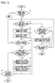
- a control flow at a time of accepting the numerical value input by means of the numerical value input screen 90 is described.
- a flow chart of Fig. 12 starts when the panel control portion 120 displays a screen on the display portion 82.
- a step S1 the panel control portion 120 determines whether the screen displayed on the display portion 82 is the numerical value input screen 90 or not. As a result of this, if the display screen is the numerical value input screen 90, the process goes to a step S2; if the display screen is not the numerical value input screen 90, the numerical value input is not accepted. In the meantime, in the case where the display screen is the numerical value input screen 90, the numerical value display region 91 in the screen displays, for example, the minimum value in the numerical value input range, the maximum value in the numerical value input range, a default value, a numerical value input before or the like as the input numerical values.
- the panel control portion 120 determines presence of the region dividing operation on the touch panel portion 83. As a result of this, if it is determined that the region dividing operation is performed, the process goes to a step S3.
- the panel control portion 120 calculates the input numerical value based on the ratio for input numerical value calculation. And, in a step S4, the panel control portion 120 makes the display portion 82 display the input numerical value that is based on the ratio for input numerical value calculation.
- step S5 the panel control portion 120 determines whether or not the predetermined period elapses after making the display portion 82 display the input numerical value. As a result of this, if it is determined that the predetermined period elapses, the process goes to the step S2; if the predetermined period does not elapse, the process goes to a step S6. Going to the step S6, the panel control portion 120 determines presence of the numerical value increase/decrease operation on the touch panel portion 83. As a result of this, if it is determined that the numerical value increase/decrease operation is performed, the process goes to a step S7.
- the panel control portion 120 calculates the input numerical value after the increase/decrease based on the ratio for increase/decrease value calculation. And, in a step S8, the panel control portion 120 makes the display portion 82 display the input numerical value after the increase/decrease that is based on the ratio for increase/decrease value calculation. Thereafter, the process goes to the step S5.
- a fixing operation is an operation for fixing the input numerical value in current display, and is, for example, a tap operation of tapping a fixing button B (see Fig. 4 to Fig. 11 ) disposed in the numerical value input screen 90.
- the panel control portion 120 ends the acceptance of the numerical value input; if a fixing operation is not performed, the process goes to the step S5.
- step S2 in a case where the region dividing operation is not performed, the process goes to a step S10. Going to the step S10, the panel control portion 120 determines whether an operation is performed on the numerical value increase/decrease button NB or not. As a result of this, if it is determined that an operation is performed on the numerical value increase/decrease button NB, the process goes to a step S11.
- the panel control portion 120 increases/decreases the input numerical value to be displayed by the display portion 82. And, the process goes to a step S12. In the meantime, in the step S10, even in a case where an operation is not performed on the numerical value increase/decrease button NB, the process goes to the step S12. Going to the step S12, the panel control portion 120 determines presence of a fixing operation on the touch panel portion 83. As a result of this, if it is determined that an fixing operation is performed, the acceptance of the numerical value input is ended; if a fixing operation is not performed, the process goes to the step S2.
Landscapes
- Engineering & Computer Science (AREA)
- General Engineering & Computer Science (AREA)
- Theoretical Computer Science (AREA)
- Human Computer Interaction (AREA)
- Multimedia (AREA)
- Signal Processing (AREA)
- Physics & Mathematics (AREA)
- General Physics & Mathematics (AREA)
- User Interface Of Digital Computer (AREA)
- Accessory Devices And Overall Control Thereof (AREA)
- Controls And Circuits For Display Device (AREA)
- Position Input By Displaying (AREA)
- Facsimiles In General (AREA)
Abstract
Description
- The present disclosure relates to a display input apparatus, an image forming apparatus including the same, and a method for controlling the display input apparatus.
- Conventionally, as a display input apparatus, a display apparatus with a touch panel is known which is installed in image forming apparatuses such as a multi-functional machine and the like, and is called an operation panel, for example. Such an operation panel accepts operations for setting and changing set values for various kinds of setting items relevant to operation of an image forming apparatus.
- There are setting items relevant to operation of an image forming apparatus that require a numerical value input when setting and changing a set value. In an example, a numerical value input becomes necessary when setting and changing the number of copies and a copy magnification. Accordingly, conventionally, when accepting a numerical value input, a numeric key pad is displayed as a software key on an operation panel. In this way, it is possible to input a desired numerical value by operating the numeric key pad (software key).
- In the operation panel that displays the numeric key pad (software key) to accept a numerical value input, for example, upon performing a tap operation (operation like tapping with a finger) on any one of numerical value keys of "0" to "9," a numerical value corresponding to the tapped numerical value key is input. However, according to this structure, in a case of inputting a two- or more-digit numerical value, it is necessary to perform the tap operation on numerical value keys two times or more. Accordingly, it is onerous and inconvenient for a user.
- In the meantime, as another example, there is an operation panel which displays a numerical value increase/decrease key (software key) including a plus key and a minus key when accepting a numerical value input. For example, upon performing the tap operation on the plus key one time, an input numerical value increases 1, while upon performing the tap operation on the minus key one time, an input numerical value decreases 1. However, according to this structure, it is necessary to perform the tap operation on the numerical value increase/decrease key many times until an input numerical value becomes a desired value. Further, it takes a long time until the input numerical value becomes the desired value.
- A display input apparatus according to a first aspect of the present disclosure includes a display portion, a touch panel portion, and a control portion. The display portion displays an input numerical value input screen for accepting an input of a numerical value and displays an input numerical value, namely, a numerical value that is input, in the numerical value input screen. The touch panel portion is disposed correspondingly to the display portion and accepts a predetermined region dividing operation on a screen of the display portion. The control portion detects, based on an output from the touch panel portion, the touch operation accepted by the touch panel portion. And, when the touch panel portion accepts a predetermined region dividing operation as a touch operation that divides a predetermined region in the numerical value input screen along a second direction that meets a first direction at right angles, the control portion sets a line, which passes through a predetermined position of the predetermined region in the second direction, as a first reference line; sets an end edge, which is opposite to the first reference line of the predetermined region in the first direction, as a second reference line; obtains a ratio for input numerical value calculation that is a ratio of a distance from the first reference line to the second reference line and a distance from the first reference line to a division line of the predetermined region that is divided by the region dividing operation; and obtains a numerical value, which is obtained by multiplying a maximum value or minimum value in a numerical value input range of the numerical value input screen by the ratio for input numerical value calculation, as the input numerical value. Besides, the display portion displays the input numerical value, which is obtained by the control portion, in the numerical value input screen.
- An image forming apparatus according to a second aspect of the present disclosure includes the above display input apparatus.
- A method for controlling a display input apparatus according to a third aspect of the present disclosure is a method for controlling a display input apparatus that includes: a display portion which displays a numerical value input screen for accepting an input of a numerical value and displays an input numerical value, namely, a numerical value that is input, in the numerical value input screen; and a touch panel portion which is disposed correspondingly to the display portion and accepts a touch operation on a screen of the display portion, the method comprising: a step in which when the touch panel portion accepts a predetermined region dividing operation as a touch operation that divides a predetermined region in the numerical value input screen along a second direction which meets a first direction at right tangles, a line, which passes through a predetermined position of the predetermined region in the second direction, is set as a first reference line, an end edge opposite, in the first direction, to the first reference line of the predetermined region is set as a second reference line, whereby a ratio for input numerical value calculation is obtained, which is, namely, a ratio of a distance from the first reference line to the second reference line and a distance from the first reference line to a division line of the predetermined region divided by the region dividing operation, and a numerical value, which is obtained by multiplying a maximum value or minimum value in a numerical value input range of the numerical value input screen by the ratio for input numerical value calculation, is obtained as the input numerical value, and; a step in which the obtained input numerical value is displayed in the numerical value input screen.
-
-
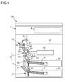
Fig. 1 is a schematic view showing an example of a multi-functional machine that includes an operation panel according to an embodiment of the present disclosure. -
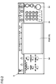
Fig. 2 is a plan view of an operation panel according to an embodiment of the present disclosure. -
Fig. 3 is a block diagram showing an example of a hardware structure of a multi-functional machine that includes an operation panel according to an embodiment of the present disclosure. -
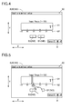
Fig. 4 is a view showing an example of a numerical value input screen that is displayed on an operation panel according to an embodiment of the present disclosure. -
Fig. 5 is a view for describing a region dividing operation (operation for inputting a numerical value) that is performed on an operation panel according to an embodiment of the present disclosure. -
Fig. 6 is a view for describing a region dividing operation that is performed on an operation panel according to an embodiment of the present disclosure. -
Fig. 7 is a view for describing a region dividing operation that is performed on an operation panel according to an embodiment of the present disclosure. -
Fig. 8 is a view for describing a region dividing operation that is performed on an operation panel according to an embodiment of the present disclosure. -
Fig. 9 is a view for describing a region dividing operation that is performed on an operation panel according to an embodiment of the present disclosure. -
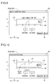
Fig. 10 is a view for describing a numerical value increase/decrease operation (operation for increasing/decreasing an input numerical value) that is performed on an operation panel according to an embodiment of the present disclosure. -
Fig. 11 is a view for describing a numerical value increase/decrease operation that is performed on an operation panel according to an embodiment of the present disclosure. -
Fig. 12 is a flow chart for describing a control flow when accepting a numerical value input on an operation panel according to an embodiment of the present disclosure. - As to an embodiment of the present disclosure, an example of a multi-functional machine is described which can execute various kinds of jobs such as a copy job, a print job, a transmission job and the like.
- As shown in
Fig. 1 , a multi-functional machine 100 (which corresponds to an "image forming apparatus") includes animage reading portion 1 and aprinting portion 2. Theimage reading portion 1 reads a document to generate image data. For example, the image data obtained by reading of theimage forming portion 1 is transmittable to an external apparatus (transmission job). - The
printing portion 2 prints an image based on image data onto a paper sheet P and outputs the paper sheet. For example, theprinting portion 2 prints an image, which is based on image data obtained by theimage reading portion 1 reading a document, onto the paper sheet P and outputs the paper sheet (copy job). Or, theprinting portion 2 prints an image, which is based on image data transmitted from an external apparatus, onto the paper sheet P and outputs the paper sheet (print job). - The
printing portion 2 is composed of a papersheet feeding portion 3, a papersheet conveying portion 4, animage forming portion 5, and afixing portion 6. The papersheet feeding portion 3 includes apickup roller 31 and a pair of papersheet feeding rollers 32, and supplies the paper sheet P housed in apaper sheet cassette 33 to a papersheet conveying path 20. The papersheet conveying portion 4 includes a plurality of pairs ofconveying rollers 41, conveys the paper sheet P along the papersheet conveying path 20, and delivers the printed paper sheet P onto adelivery tray 42. - The
image forming portion 5 includes aphotosensitive drum 51, acharging device 52, anexposure device 53, a developingdevice 54, atransfer roller 55, and acleaning device 56. And, theimage forming portion 5 forms a toner image based on image data, and transfers the toner image to the paper sheet P. Thefixing portion 6 includes aheat roller 61 and apressure roller 62, heats and pressures the toner image transferred to the paper sheet P to fix the toner image. - Besides, the
multi-functional machine 100 includes anoperational panel 8 shown inFig. 2 . Theoperation panel 8 is disposed on a front side (e.g., a place indicate by a broken line ofFig. 1 ) of themulti-functional machine 100. In the meantime, theoperation panel 8 corresponds to a "display input apparatus." - The
operation panel 8 is provided with anoperation display portion 81. Theoperation display portion 81 includes adisplay portion 82 and atouch panel portion 83. Thedisplay portion 82 is a display panel such as a liquid crystal display panel, an organic EL display panel or the like. Thetouch panel portion 83 is a multi-touch panel that can detect simultaneously a plurality of touch positions, and is disposed to cover a display surface of thedisplay portion 82. And, theoperation display portion 81 displays buttons (software keys) for accepting various kinds of settings and a message on thedisplay portion 82, and accepts various kinds of settings via thetouch panel portion 83. In the meantime, theoperation panel 8 is also provided with various kinds of hardware keys such as a start key, a stop key, a reset key , a numeric key pad and the like. - As show in
Fig. 3 , themulti-functional machine 100 includes amain control portion 110. Themain control portion 110 includes amain CPU 111, animage processing portion 112, and astorage portion 113. Theimage processing portion 112 includes an ASIC dedicated to image processing and the like, and applies image processings (enlargement/reduction, concentration conversion, data format conversion and the like) to image data. Thestorage portion 113 includes a ROM, a RAM and the like, and stores a program for control and data. And, themain control portion 110 controls operation of each portion of themulti-functional machine 100 based on the program and data stored in thestorage portion 113. - Specifically, the
main control portion 110 is connected to theimage reading portion 1 and the printing portion 2 (papersheet feeding portion 3, papersheet conveying portion 4,image forming portion 5, and fixing portion 6). And, themain control portion 110 controls a reading operation of theimage reading portion 1 and controls a printing operation of theprinting portion 2. - Besides, the
main control portion 110 is connected to apanel control portion 120. Thepanel control portion 120 includes aCPU 121 and astorage portion 122, receives instructions from themain control portion 110 to control a display operation of theoperation panel 8 and detects an operation performed on theoperation panel 8. For example, thepanel control portion 120 makes thedisplay portion 82 display a button (software key), if a touch operation is performed on the button, detects, based on an output from thetouch panel portion 83, the button that accepts the touch operation. Besides, if a push-down operation of pushing down thehardware key 84 is performed, based on an output from a switch that is switched in on/off by the push-down of thehardware key 84, thepanel control portion 120 detects thehardware key 84 that accepts the push-down operation. - Besides, the
main control portion 110 is connected to acommunication portion 130. Thecommunication portion 130 is communicably connected to external apparatuses (computer 200 and facsimile 300). And, thecommunication portion 130 receives an instruction from themain control portion 110 and performs transmission/reception of image data with the external apparatuses. - When necessary, the
operation panel 8 accepts a numerical value input from a user. For example, when setting a copy magnification at an arbitrary magnification (magnification other than standard magnification) and setting a document reading size at an arbitrary size (size other than standard size), it is necessary to input numerical values as the copy magnification and the document reading size. Besides, when setting the maximum holding number of image data transmitted from the external apparatus, it is necessary to input a numerical value as the maximum holding number. Besides, when setting an identification number to be allocated to an address registered in an address book, it is necessary to input a numerical value as the identification number. Further, in a case where a power saving mode (sleep mode) is incorporated in themulti-functional machine 100, it becomes necessary to input a numerical value when setting a period located before a time the power saving mode starts to work. In the meantime, the setting items described here that require numerical value inputs are examples, and there are many other setting items that require numerical value inputs. - When accepting a numerical value input, the
panel control portion 120 makes thedisplay portion 82 display a numericalvalue input screen 90 shown inFig. 4 . And, thepanel control portion 120 makes thetouch panel portion 83 accept the numerical value input. In the meantime, the numericalvalue input screen 90 shown inFig. 4 is an example, and it is possible to change a screen layout and the like. - The numerical
value input screen 90 includes a numericalvalue display region 91 for displaying a numerical value (hereinafter, called an input numerical value) input by the user. This numericalvalue display region 91 is formed to have a substantially rectangular shape that is long in a left-right direction when seeing from an apparatus front side. In the meantime, the numericalvalue display region 91 corresponds to a "predetermined region." Besides, a long-edge direction (left-right direction) of the numericalvalue display region 91 corresponds to a "first direction," while a short-edge direction, which meets the long-edge direction of the numericalvalue display region 91 at right angles, corresponds to a "second direction." In the following description, the long-edge direction (first direction) of the numericalvalue display region 91 is called an X direction, while the short-edge (second direction) direction of the numericalvalue display region 91 is called a Y direction. - Besides, the numerical
value input screen 90 is provided with a numerical value increase/decrease button NB that includes a plus button B1 and a minus button B2. And, based on an output from thetouch panel portion 83, thepanel control portion 120 detects a tap operation (operation like tapping with a finger) on the numerical value increase/decrease button NB. - If the tap operation is performed on the plus button B1 one time, the
panel control portion 120 makes thedisplay portion 82 display a numerical value, which is obtained by adding "1" to an input numerical value in current display, as a new input numerical value; if the tap operation is performed on the minus button B2 one time, thepanel control portion 120 makes thedisplay portion 82 display a numerical value, which is obtained by subtracting "1" from an input numerical value in current display, as a new input numerical value. - When the
display portion 82 displays the numericalvalue input screen 90, thepanel control portion 120 detects whether a region dividing operation is performed on thetouch panel portion 83 or not. In the meantime, a region dividing operation is predetermined as a touch operation that divides the numericalvalue display region 91 along the Y direction. For example, as shown inFig. 5 , thetouch panel portion 83 accepts a touch operation (operation called a slide operation or the like), which slides a touch position to divide the numericalvalue display region 91 along the Y direction, as a region dividing operation. And, upon detecting a region dividing operation on thetouch panel portion 83, thepanel control portion 120 obtains a division ratio of the numericalvalue display region 91 divided by the region dividing operation. - At this time, as shown in
Fig. 6 , thepanel control portion 120 identifies a division line DL of the numericalvalue display region 91 divided by the region dividing operation. This division line DL is a line that is along the Y direction and substantially overlaid on the slide direction of the touch position at the time of region dividing operation. In the meantime, as shown inFig. 7 , there is a case where the slide direction (white arrow direction inFig. 7 ) of the touch position at the time of region dividing operation deviates from the Y direction. Because of this, for example, thetouch panel portion 120 sets beforehand an intermediate line ML that extends in the X direction between upper and lower edges of the numericalvalue display region 91, and identifies a line, which passes, in the Y direction, through an intersection between the line along the slide direction of the touch position at the time of region dividing operation and the intermediate line ML, as the division line DL. Or, a line, which passes, in the Y direction, through an intersection between the line along the slide direction of the touch position at the time of region dividing operation and the upper edge or lower edge of the numericalvalue display region 91, may be set as the division line DL. - Back to
Fig. 6 , when obtaining the division ratio of the numericalvalue display region 91, thepanel control portion 120 sets a line (line extending along the Y direction), which passes through a predetermined position of the numericalvalue display region 91 in the Y direction, as a first reference line L1, and sets an end edge (edge extending along the Y direction) of the numericalvalue display region 91 opposite to the first reference line L1 in the X direction, as a second reference line L2. At this time, if a numerical value input range of the numericalvalue input screen 90 does not bridge a positive value and a negative value, thepanel control portion 120 sets one-side (right side) end edge as the first reference line L1 which is one of both end edges of the numericalvalue display region 91 opposite to each other in the X direction, and sets the other-side (left side) end edge as the second reference line L2 which is the other one of both end edges of the numericalvalue display region 91 opposite to each other in the X direction. And, thepanel control portion 120 obtains a ratio of a distance D1 from the first reference line L1 to the second reference line L2 and a distance D2 from the first reference line L1 to the division line DL as a division ratio of the numericalvalue display region 91. The division ratio of the numericalvalue display region 91 obtained here corresponds to a "ratio for input numerical value calculation," and is called a ratio for input numerical value calculation in the following description. - Upon obtaining the ratio for input numerical value calculation, the
panel control portion 120 calculates an input numerical value based on the ratio for input numerical value calculation. Specifically, thepanel control portion 120 obtains a numerical value, which is obtained by multiplying a maximum value or minimum value in the numerical value input range of the numericalvalue input screen 90 by the ratio for input numerical value calculation, as an input numerical value. And, thepanel control portion 120 makes thedisplay portion 82 display the obtained input numerical value. - According to such a structure, by performing the region dividing operation such that the ratio (ratio for input numerical value calculation) of the distance D2 from the first reference line L1 to the division line DL of the numerical
value display region 91 to the distance D1 from the first reference line L1 to the second reference line L2 becomes equal to a ratio of a desired value (numerical value to be input) to the maximum value or minimum value in the numerical value input range of the numericalvalue input screen 90, it becomes possible to input the desired value by means of only one operation. In this way, operations at the time of numerical value input decrease; accordingly, convenience for the user improves. - Besides, the touch operation, which slides the touch position to divide the numerical
value display region 91 along the Y direction, is used as the region dividing operation; accordingly, the region dividing operation becomes straightforward and easy to understand. In the meantime, the touch operation, which slides the touch position to divide the numericalvalue display region 91 along the Y direction, may be used as the region dividing operation; however, a tap operation of tapping the numericalvalue display region 91 only one time may be used as the region dividing operation. In this case, a line, which passes through the tap position at the time of region dividing operation in the Y direction, may be used as the division line DL of the numericalvalue display region 91. - Besides, the region dividing operation is accepted by means of the numerical
value display region 91; accordingly, it is unnecessary to additionally secure a region, in the numericalvalue input screen 90, for accepting the region dividing operation. In this way, the degree of freedom of layout of the numericalvalue input screen 90 increases. However, the region dividing operation may be accepted by means of a region other than the numericalvalue display region 91 in the numericalvalue input screen 90. - Besides, the end edge on the one side of the numerical
value display region 91 in the X direction and the end edge on the other side of the numericalvalue display region 91 in the X direction are set as the first reference line L1 and the second reference line L2, respectively; accordingly, it becomes easy to understand which position of the numericalvalue display region 91 should be used as a reference to perform the region dividing operation. - Here, in a case where the values in the input range of the numerical
value input screen 90 are only positive values, thepanel control portion 120 obtains a numerical value, which is obtained by multiplying the maximum value in the numerical value input range by the ratio for input numerical value calculation, as the input numerical value. As an example, as shown inFig. 8 , it is assumed that in the numericalvalue input screen 90 having a numerical value input range of "1" to "100," the region dividing operation is performed such that the ratio of the distance D2 to the distance D1 becomes 0.62. In this case, the maximum value in the numerical value input range is "100"; accordingly, the input numerical value obtained by thepanel control portion 120 becomes "62 (= 100 × 0.62)." In this way, thedisplay portion 82 displays "62" as the input numerical value. - Besides, in a case where the values in the input range of the numerical
value input screen 90 are only negative values, thepanel control portion 120 obtains a numerical value, which is obtained by multiplying the minimum value in the numerical value input range by the ratio for input numerical value calculation, as the input numerical value. As an example, although not shown, it is assumed that in the numericalvalue input screen 90 having a numerical value input range of "-1" to "-100," the region dividing operation is performed such that the ratio of the distance D2 to the distance D1 becomes 0.62. In this case, the minimum value in the numerical value input range is "-100"; accordingly, the input numerical value obtained by thepanel control portion 120 becomes "-62 (= -100 × 0.62)." In the meantime, in the case where the numerical values in the input range of the numericalvalue input screen 90 are only negative values, of both end edges (both end edges extending along the Y direction) of the numericalvalue display region 91 opposite to each other in the X direction, the end edge on the one side (right side) may be set as the second reference line L2, and the end edge on the other side (left side) may be set as the first reference line L1 (they may be reversed to the case where the numerical values in the numerical value input range of the numericalvalue input screen 90 are only positive values). - Further, there is a case where the numerical value input range of the numerical
value input screen 90 bridge a positive value and a negative value. In this case, thepanel control portion 120 sets a line, which passes, in the Y direction, through a position between both end edges of the numericalvalue display region 91 opposite to each other in the X direction, as the first reference line L1. And, if the region dividing operation is performed on one side of the numericalvalue display region 91 in the X direction with respect to the first reference line L1, thepanel control portion 120 sets the end edge on the one side of the numericalvalue display region 91 as the second reference line L2 to obtain the ratio for input numerical value calculation, and obtains a numerical value, which is obtained by multiplying the maximum positive value in the numerical value input range of the numericalvalue input screen 90 by the ratio for input numerical value calculation, as the input numerical value. On the other hand, if the region dividing operation is performed on the other side of the numericalvalue display region 91 opposite to the one side, thepanel control portion 120 sets the end edge on the other side of the numericalvalue display region 91 as the second reference line L2 to obtain the ratio for input numerical value calculation, and obtains a numerical value, which is obtained by multiplying the minimum negative value in the numerical value input range of the numericalvalue input screen 90 by the ratio for input numerical value calculation, as the input numerical value. - According to such a structure, even in the case where the numerical value input range of the numerical
value input screen 90 bridges a positive value and a negative value, it is possible to selectively input any one of the positive value and negative value by means of only one region dividing operation. - As an example, as shown in
Fig. 9 , it is assumed that the numericalvalue input screen 90 has a numerical value input range of "-50" to "50." In this case, for example, thepanel control portion 120 sets a line, which passes, in the Y direction, through a middle position between both end edges of the numericalvalue display region 91 opposite to each other in the X direction, as the first reference line L1. And, in a case where the region dividing operation is performed on one side (left side) of the numericalvalue display region 91 with respect to the first reference line L1, thepanel control portion 120 sets the end edge on the one side of the numericalvalue display region 91 as the second reference line L2 to obtain the ratio for input numerical value calculation, and obtains a numerical value, which is obtained by multiplying the maximum positive value "50" in the numerical value input range of the numericalvalue input screen 90 by the ratio for input numerical value calculation, as the input numerical value. On the other hand, in a case where the region dividing operation is performed on the other side (right side) of the numericalvalue display region 91 with respect to the first reference line L1, thepanel control portion 120 sets the end edge on the other side of the numericalvalue display region 91 as the second reference line L2 to obtain the ratio for input numerical value calculation, and obtains a numerical value, which is obtained by multiplying the minimum negative value "-50" in the numerical value input range of the numericalvalue input screen 90 by the ratio for input numerical value calculation, as the input numerical value. - In the meantime, for example, in the numerical value input screen 90 (see
Fig. 4 to Fig. 8 ) that has the numerical value input range of "1" to "100," if a touch operation, which slides the touch position along the end edge of the numericalvalue display region 91 used as the second reference line L2, is performed as the region dividing operation, the second reference line L2 and the division line DL are overlaid on each other. In other words, the ratio for input numerical value calculation, which is the ratio of the distance D1 and the distance D2, becomes "1." Accordingly, by sliding the touch position along the end edge of the numericalvalue display region 91 used as the second reference line L2, it is possible to input the maximum value "100 (= 100x1)." As another example, in the case where the numerical value input range is from "-1" to "-100," it is possible to input the minimum value "-100 (=-100×1)." - In the meantime, in the numerical
value input screen 90 having the numerical value input range of "1" to "100," if a touch operation, which slides the touch position along the end edge of the numericalvalue display region 91 used as the first reference line L1, is performed as the region dividing operation, the first reference line L1 and the division line DL are overlaid on each other, and the input numerical value obtained by thepanel control portion 120 becomes "0" which is outside the numerical value input range. In such a case, thepanel control portion 120 does not make thedisplay portion 82 display the obtained numerical value. Besides, in this case, thedisplay portion 82 performs at least one notification of a notification of being unable to input a numerical value and a notification of prompting a re-input of a numerical value (displays a notification message). - The
panel control portion 120 makes thedisplay portion 82 display a scale 92 (seeFig. 4 to Fig. 9 ) that serves as a reference as to what value is input in a case where the region dividing operation is performed on thetouch panel portion 83. For example, thescale 92 is disposed on the lower edge of the upper and lower edges of the numericalvalue display region 91. Or, although not shown, thescale 92 may be disposed on the upper edge of the upper and lower edges of the numericalvalue display region 91. - When displaying the
scale 92, thedisplay portion 82 divides the numericalvalue display region 91 at a predetermined division position. And, thedisplay portion 82 displays a numerical value, which is used as the input numerical value in a case where the region dividing operation is performed to divide the numericalvalue display region 91 along a line that passes through the division position in the Y direction, as thescale 92. - According to such a structure, it is possible to perform the region dividing operation by using the
scale 92 as the reference; accordingly, the input numerical value does not become a numerical value that is dramatically far from a desired value. - For example, in the case where the numerical
value input screen 90 has the numerical value input range of "1" to "100," although not especially limited, as shown inFig. 4 to Fig. 8 , the numericalvalue display region 91 is divided into 5 sections at equal intervals (there are four division positions). And, in this case, numerical values as thescales 92 respectively disposed at the four division positions are "80," "60," "40," and "20" in order from the division position on one side (left side). In the meantime, a numerical value "0" may be attached as thescale 92 to the position of the end edge of the numericalvalue display region 91 used as the first reference line L1, and a numerical value "100" may be attached as thescale 92 to the position of the end edge of the numericalvalue display region 91 used as the second reference line L2. - Here, in the case where the numerical value input range bridges a positive value and a negative value (case where a line, which passes, in the Y direction, through a position between both end edges of the numerical
value display region 91 opposite to each other in the X direction, is used as the first reference line L1), it is hard for the user to understand which position should be used as the reference to perform the region dividing operation. Accordingly, in this case, as shown inFig. 9 , it is preferable that a division position is set at the position (position where the input numerical value becomes "0" when the region dividing operation is performed) of the first reference line L1 at the least and a numerical value "0" is attached as thescale 92 to the division position. As an example,Fig. 9 shows, besides the position of the first reference line L1, thescale 92 which uses, as division positions, a position where the input numerical value becomes "25" when the region dividing operation is performed and a position where the input numerical value becomes "-25" when the region dividing operation is performed. - The
panel control portion 120 detects a region dividing operation on thetouch panel portion 83 and makes thedisplay portion 82 display the input numerical value that is obtained in accordance with the region dividing operation, thereafter, makes thetouch panel portion 83 accept a predetermined numerical value increase/decrease operation as a touch operation of increasing/decreasing (fine adjustment) the input numerical value in current display until a predetermined period (e.g., a few seconds to more than ten seconds) elapses. For example, thetouch panel portion 83 accepts the region dividing operation, thereafter, accepts a region dividing operation, which is accepted again by a time the predetermined period elapses, as the numerical value increase/decrease operation. - When making the
touch panel portion 83 accept the numerical value increase/decrease operation until the predetermined period elapses, as shown inFig. 10 , thepanel control portion 120 sets a line (line extending along the Y direction), which passes, in the Y direction, through a predetermined position between both end edges of the numericalvalue display region 91 opposite to each other in the X direction, as a third reference line L3. For example, at the time of accepting the numerical value increase/decrease operation, a line, which passes, in the Y direction, through a middle position between both end edges of thenumerical display region 91 opposing the X direction, is set as the third reference line L3. - At this time, if the
touch panel portion 83 accepts the numerical value increase/decrease operation (if thetouch panel portion 83 accepts again the region dividing operation before the predetermined period elapses), thepanel control portion 120 identifies the division line DL of the numericalvalue display region 91 divided by the numerical value increase/decrease operation. Hereinafter, the division line DL of the numericalvalue display region 91 divided by the numerical value increase/decrease operation is called a division line DLA. - And, in a case where the numerical value increase/decrease operation is performed on one side (here, left side) of the numerical
value display region 91 in the X direction with respect to the third reference line L3, thepanel control portion 120 sets the end edge on the one side of the numericalvalue display region 91 as a fourth reference line L4, and obtains a ratio of a distance D3 from the third reference line L3 to the fourth reference line L4 and a distance D4 from the third reference line L3 to the division line DLA of the numericalvalue display region 91 divided by the numerical value increase/decrease operation as a division ratio of the numericalvalue display region 91. The division ratio of the numericalvalue display region 91 obtained here corresponds to a "ratio for increase/decrease value calculation," and it is called a ratio for increase/decrease value calculation in the following description. - Thereafter, the
panel control portion 120 calculates an input numerical value after the increase/decrease based on the ratio for increase/decrease value calculation. Specifically, thepanel control portion 120 multiplies a predetermined increase/decrease value by the ratio for increase/decrease value calculation, and obtains a numerical value, which is obtained by increasing the input numerical value in current display by the numerical value obtained by the multiplication, as the input numerical value after the increase/decrease. In the meantime, the predetermined increase/decrease value is a predetermined numerical value, but can be changed in accordance with the numerical value input range of the numerical value input screen 90 (e.g., the larger the numerical value input range of the numericalvalue input screen 90 is, the larger the predetermined increase/decrease value may be made). - On the other hand, in a case where the numerical value increase/decrease operation is performed on the other side (here, right side) of the numerical
value display region 91 opposite to the one side in the X direction with respect to the third reference line L3, thepanel control portion 120 sets the end edge on the other side of the numericalvalue display region 91 as the fourth reference line L4, and obtains the ratio for increase/decrease value calculation. Thereafter, thepanel control portion 120 obtains a numerical value, which is obtained by decreasing the input numerical value in current display by a numerical value obtained by multiplying the predetermined increase/decrease value by the ratio for increase/decrease value calculation, as the input numerical value after the increase/decrease. - Upon obtaining the input numerical value after the increase/decrease, the
panel control portion 120 makes thedisplay portion 82 display the input numerical value after the increase/decrease. In other words, thedisplay portion 82 newly displays the input numerical value after the increase/decrease instead of the input numerical value in current display. - According to such a structure, by only performing again the region dividing operation (numerical value increase/decrease operation) by the time the predetermined period elapses, it is possible to increase/decrease (fine adjustment) the input numerical value. In other words, when finely adjusting the input numerical value, it is unnecessary to perform many times the operation of increasing/decreasing the input numerical value by tapping the numerical value increase/decrease button NB.
- For example, as shown in
Fig. 11 , it is assumed that in the numericalvalue input screen 90 where the predetermined increase/decrease value is set at "10," "62" is in current display as the input numerical value in accordance with the region dividing operation performed already. Further, it is assumed that the numerical value increase/decrease operation is performed on one side with respect to the third reference line L3 and the ratio of the distance D4 to the distance D3 is "0.3." In this case, the ratio for increase/decrease value calculation becomes "0.3," and the numerical value obtained by multiplying the predetermined increase/decrease value "10" by the ratio "0.3" for increase/decrease value calculation becomes "3 (= 10 × 0.3)";accordingly, the input numerical value after the increase/decrease obtained by thepanel control portion 120 becomes "65 (= 62+3)." Accordingly, thedisplay portion 82 switches the input numerical value from "62" to "65" to display "65." - Besides, when making the
touch panel portion 83 accept the numerical value increase/decrease operation, thepanel control portion 120 makes thedisplay portion 82 display a scale 93 (seeFig. 10 to Fig. 11 ) that serves as a reference to indicate by what value the input numerical value in current display increases or decreases in the case where the numerical value increase/decrease operation is performed on thetouch panel portion 83. For example, the scale 93 is disposed on the lower edge of the upper and lower edges of the numericalvalue display region 91. Or, although not shown, the scale 93 may be disposed on the upper edge of the upper and lower edges of the numericalvalue display region 91. - When displaying the scale 93, the
display portion 82 divides the numericalvalue display region 91 at a predetermined division position. And, thedisplay portion 82 displays a numerical value, which indicates by what value the input numerical value in current display increases or decreases in a case where the numerical value increase/decrease operation is performed to divide the numericalvalue display region 91 along a line that passes through the division position in the Y direction, as the scale 93. - In the meantime, after a numerical value is input by means of the region dividing operation, it is also possible to perform the fine adjustment of the input numerical value by means of an operation on the numerical value increase/decrease button NB. Or, the fine adjustment of the input numerical value is performed by means of the numerical value increase/decrease operation, thereafter, it is also possible to further perform the fine adjustment of the input numerical value by means of an operation on the numerical value increase/decrease button NB.
- Hereinafter, with reference to
Fig. 12 , a control flow at a time of accepting the numerical value input by means of the numericalvalue input screen 90 is described. In the meantime, a flow chart ofFig. 12 starts when thepanel control portion 120 displays a screen on thedisplay portion 82. - In a step S1, the
panel control portion 120 determines whether the screen displayed on thedisplay portion 82 is the numericalvalue input screen 90 or not. As a result of this, if the display screen is the numericalvalue input screen 90, the process goes to a step S2; if the display screen is not the numericalvalue input screen 90, the numerical value input is not accepted. In the meantime, in the case where the display screen is the numericalvalue input screen 90, the numericalvalue display region 91 in the screen displays, for example, the minimum value in the numerical value input range, the maximum value in the numerical value input range, a default value, a numerical value input before or the like as the input numerical values. - Going to the step S2, the
panel control portion 120 determines presence of the region dividing operation on thetouch panel portion 83. As a result of this, if it is determined that the region dividing operation is performed, the process goes to a step S3. - Going to the step S3, the
panel control portion 120 calculates the input numerical value based on the ratio for input numerical value calculation. And, in a step S4, thepanel control portion 120 makes thedisplay portion 82 display the input numerical value that is based on the ratio for input numerical value calculation. - Next, in a step S5, the
panel control portion 120 determines whether or not the predetermined period elapses after making thedisplay portion 82 display the input numerical value. As a result of this, if it is determined that the predetermined period elapses, the process goes to the step S2; if the predetermined period does not elapse, the process goes to a step S6. Going to the step S6, thepanel control portion 120 determines presence of the numerical value increase/decrease operation on thetouch panel portion 83. As a result of this, if it is determined that the numerical value increase/decrease operation is performed, the process goes to a step S7. - Going to the step S7, the
panel control portion 120 calculates the input numerical value after the increase/decrease based on the ratio for increase/decrease value calculation. And, in a step S8, thepanel control portion 120 makes thedisplay portion 82 display the input numerical value after the increase/decrease that is based on the ratio for increase/decrease value calculation. Thereafter, the process goes to the step S5. - Besides, in the step S6, in a case where the numerical value increase/decrease operation is not performed, the process goes to a step S9. Going to the step S9, the
panel control portion 120 determines presence of a fixing operation on thetouch panel portion 83. In the meantime, a fixing operation is an operation for fixing the input numerical value in current display, and is, for example, a tap operation of tapping a fixing button B (seeFig. 4 to Fig. 11 ) disposed in the numericalvalue input screen 90. As a result of determining presence of a fixing operation on thetouch panel portion 83, if it is determined that a fixing operation is performed, thepanel control portion 120 ends the acceptance of the numerical value input; if a fixing operation is not performed, the process goes to the step S5. - In the meantime, in the step S2, in a case where the region dividing operation is not performed, the process goes to a step S10. Going to the step S10, the
panel control portion 120 determines whether an operation is performed on the numerical value increase/decrease button NB or not. As a result of this, if it is determined that an operation is performed on the numerical value increase/decrease button NB, the process goes to a step S11. - Going to the step S11, based on the operation on the numerical value increase/decrease button NB, the
panel control portion 120 increases/decreases the input numerical value to be displayed by thedisplay portion 82. And, the process goes to a step S12. In the meantime, in the step S10, even in a case where an operation is not performed on the numerical value increase/decrease button NB, the process goes to the step S12. Going to the step S12, thepanel control portion 120 determines presence of a fixing operation on thetouch panel portion 83. As a result of this, if it is determined that an fixing operation is performed, the acceptance of the numerical value input is ended; if a fixing operation is not performed, the process goes to the step S2. - It should be considered that the embodiments disclosed this time are examples in all respects and are not limiting. The scope of the present disclosure is not indicated by the above description of the embodiments but by the claims, and all modifications within the scope of the claims and the meaning equivalent to the claims are covered.
- The above embodiments of the invention as well as the appended claims and figures show multiple characterizing features of the invention in specific combinations. The skilled person will easily be able to consider further combinations or sub-combinations of these features in order to adapt the invention as defined in the claims to his specific needs.
Claims (11)
- A display input apparatus (8) comprising:a display portion (82) that displays a numerical value input screen (90) for accepting an input of a numerical value and an input numerical value, namely, a numerical value that is input, on the numerical value input screen (90),a touch panel portion (83) that is disposed correspondingly to the display portion (82) and accepts a touch operation on a screen of the display portion (82), anda control portion (120) that detects, based on an output from the touch panel portion (83), the touch operation accepted by the touch panel portion (83),wherein when the touch panel portion (83) accepts a predetermined region dividing operation as a touch operation that divides a predetermined region (91) in the numerical value input screen (90) along a second direction that meets a first direction at right angles,the control portion (120) sets a line, which passes through a predetermined position of the predetermined region (91) in the second direction, as a first reference line (L1); sets an end edge, which is opposite to the first reference line (L1) of the predetermined region (91) in the first direction, as a second reference line (L2); obtains a ratio for input numerical value calculation that is a ratio of a distance from the first reference line (L1) to the second reference line (L2) and a distance from the first reference line (L1) to a division line (DL) of the predetermined region (91) that is divided by the region dividing operation; and obtains a numerical value, which is obtained by multiplying a maximum value or minimum value in a numerical value input range of the numerical value input screen (90) by the ratio for input numerical value calculation, as the input numerical value, andthe display portion (82) displays the input numerical value, which is obtained by the control portion (120), in the numerical value input screen (90).
- The display input apparatus (8) according to claim 1, wherein
the touch panel portion (83) accepts a touch operation, which slides a touch position along the second direction to divide the predetermined region (91), as the region diving operation. - The display input apparatus (8) according to claim 1 or 2, wherein
the predetermined region (91) is a numerical value display region (91) where the input numerical value is displayed. - The display input apparatus (8) according to any one of claims 1 to 3, wherein
the display portion (82) divides the predetermined region (91) at a predetermined division position, and displays a numerical value, which is used as the input numerical value in a case where the region dividing operation is performed to divide the predetermined region (91) along a line that passes through the division position in the second direction, as a scale (92). - The display input apparatus (8) according to any one of claims 1 to 4, wherein
in a case where the numerical value input range of the numerical value input screen (90) does not bridge a positive value and a negative value, the control portion (120) obtains the input numerical value by setting one end edge of both end edges of the predetermined region (91), which are opposite to each other in the first direction, as the first reference line (L1) and setting another end edge opposite to the one end edge as the second reference line (L2). - The display input apparatus (8) according to any one of claims 1 to 5, wherein
in a case where the numerical value input range of the numerical value input screen (90) bridges a positive value and a negative value,
the control portion (120) sets a line, which passes, in the second direction, through a predetermined position between both end edges of the predetermined region (91) opposite to each other in the first direction, as the first reference line (L1); in a case where the region dividing operation is performed on one side of the predetermined region (91) in the first direction with respect to the first reference line (L1), obtains the ratio for input numerical value calculation by setting an end edge on the one side of the predetermined region (91) as the second reference line (L2); obtains a numerical value, which is obtained by multiplying a maximum positive value in the numerical value input range of the numerical value input screen (90) by the ratio for input numerical value calculation, as the input numerical value; in a case where the region dividing operation is performed on another side of the predetermined region (91) opposite to the one side, obtains the ratio for input numerical value calculation by setting an end edge on the other side of the predetermined region (91) as the second reference line (L2), and obtains a numerical value, which is obtained by multiplying a minimum negative value in the numerical value input range of the numerical value input screen (90) by the ratio for input numerical value calculation, as the input numerical value. - The display input apparatus (8) according to any one of claims 1 to 6, wherein
in a case where the second reference line (L2) and the division lien (DL) are overlaid on each other, the display portion (82) displays the maximum value or minimum value in the numerical value input range of the numerical value input screen (90) as the input numerical value in the numerical value input screen (90). - The display input apparatus (8) according to any one of claims 1 to 7, wherein
in a case where the second reference line (L1) and the division line (DL) are overlaid on each other, the display portion (82) performs at least one notification of a notification of being unable to input a numerical value and a notification of prompting a re-input of a numerical value. - The display input apparatus (8) according to any one of claims 1 to 8, wherein
when the touch panel portion (83) accepts the region dividing operation and the touch panel portion (83) accepts again the region dividing operation by a time when a predetermined period elapses after the display portion (82) displays the input numerical value in the numerical value input screen (90),
the touch panel portion (83) accepts the region dividing operation, which is accepted again by the time when the predetermined period elapses, as a numerical value increase/decrease operation, and
the control portion (120) sets a line, which passes, in the second direction, through a predetermined position between both end edges of the predetermined region (91) opposite to each other in the first direction, as a third reference line (L3); in a case where the numerical value increase/decrease operation is performed on one side of the predetermined region (91) in the first direction with respect to the third reference line (L3), sets an end edge on the one side of the predetermine region (91) as a fourth reference line (L4) to obtain a ratio for increase/decrease value calculation that is a ratio of a distance from the third reference line (L3) to the fourth reference line (L4) and a distance from the third reference line (L3) to a division line (DL) of the predetermined region (91) divided by the numerical value increase/decrease operation, and obtains a numerical value, which is obtained by increasing the input numerical value in current display by a numerical value that is obtained by multiplying a predetermined increase/decrease value by the ratio for increase/decrease value calculation, as the input numerical value after increase/decrease; in a case where the numerical value increase/decrease operation is performed on another side of the predetermined region (91) opposite to the one side, sets an end edge on the other side of the predetermined region as the fourth reference line (L4) to obtain the ratio for increase/decrease value calculation, and obtains a numerical value, which is obtained by decreasing the input numerical value in current display by a numerical value that is obtained by multiplying the predetermined increase/decrease value by the ratio for increase/decrease value calculation, as the input numerical value after increase/decrease, and
the display portion (82) newly displays the input numerical value after the increase/decrease obtained by the control portion (120) instead of the input numerical value in current display. - An image forming apparatus (100) comprising the display input apparatus (8) according to claim 1.
- A method for controlling a display input apparatus that includes: a display portion (82) which displays a numerical value input screen (90) for accepting an input of a numerical value and displays an input numerical value, namely, a numerical value that is input, in the numerical value input screen (90); and a touch panel portion (83) which is disposed correspondingly to the display portion (82) and accepts a touch operation on a screen of the display portion (82), the method comprising:a step in which when the touch panel portion (83) accepts a predetermined region dividing operation as a touch operation that divides a predetermined region (91) in the numerical value input screen (90) along a second direction which meets a first direction at right tangles, a line, which passes, in the second direction, through a predetermined position of the predetermined region, is set as a first reference line (L1), an end edge opposite, in the first direction, to the first reference line (L1) of the predetermined region (91) is set as a second reference line (L2), whereby a ratio for input numerical value calculation is obtained, which is, namely, a ratio of a distance from the first reference line (L1) to the second reference line (L2) and a distance from the first reference line (L1) to a division line (DL) of the predetermined region (91) divided by the region dividing operation, and a numerical value, which is obtained by multiplying a maximum value or minimum value in a numerical value input range of the numerical value input screen (90) by the ratio for input numerical value calculation, is obtained as the input numerical value, anda step in which the obtained input numerical value is displayed in the numerical value input screen (90).
Applications Claiming Priority (1)
| Application Number | Priority Date | Filing Date | Title |
|---|---|---|---|
| JP2013243968A JP5982349B2 (en) | 2013-11-26 | 2013-11-26 | Display input device and image forming apparatus having the same |
Publications (2)
| Publication Number | Publication Date |
|---|---|
| EP2876535A1 true EP2876535A1 (en) | 2015-05-27 |
| EP2876535B1 EP2876535B1 (en) | 2018-09-19 |
Family
ID=51900210
Family Applications (1)
| Application Number | Title | Priority Date | Filing Date |
|---|---|---|---|
| EP14192778.0A Not-in-force EP2876535B1 (en) | 2013-11-26 | 2014-11-12 | Display input apparatus, image forming apparatus having the same, and method for controlling the display input apparatus |
Country Status (4)
| Country | Link |
|---|---|
| US (1) | US9380178B2 (en) |
| EP (1) | EP2876535B1 (en) |
| JP (1) | JP5982349B2 (en) |
| CN (1) | CN104683620B (en) |
Citations (1)
| Publication number | Priority date | Publication date | Assignee | Title |
|---|---|---|---|---|
| US20010024196A1 (en) * | 2000-03-10 | 2001-09-27 | Nissei Plastic Industrial Co., Ltd. | Input device for injection molding machine |
Family Cites Families (9)
| Publication number | Priority date | Publication date | Assignee | Title |
|---|---|---|---|---|
| JP2000245981A (en) * | 1999-03-04 | 2000-09-12 | Juki Corp | Sewing machine with data setting function |
| ES2194623T3 (en) * | 2001-09-11 | 2006-02-16 | TRW AUTOMOTIVE ELECTRONICS & COMPONENTS GMBH & CO. KG | REGULATION SYSTEM FOR A VEHICLE AIR CONDITIONING DEVICE. |
| JP5546114B2 (en) | 2008-08-27 | 2014-07-09 | スパンション エルエルシー | Semiconductor device manufacturing method and semiconductor device |
| KR20100027686A (en) * | 2008-09-03 | 2010-03-11 | 엘지전자 주식회사 | Mobile terminal and method for controlling the same |
| JP5081939B2 (en) | 2010-03-23 | 2012-11-28 | シャープ株式会社 | Operating device, electronic device and image processing apparatus including the operating device, and information display method in the operating device |
| US8804148B2 (en) * | 2011-09-26 | 2014-08-12 | Brother Kogyo Kabushiki Kaisha | Image forming apparatus and non-transitory computer readable medium storing a program for controlling the same |
| US9772759B2 (en) * | 2011-10-14 | 2017-09-26 | Apple Inc. | Device, method, and graphical user interface for data input using virtual sliders |
| US9202433B2 (en) * | 2012-03-06 | 2015-12-01 | Apple Inc. | Multi operation slider |
| JP6157215B2 (en) * | 2013-05-23 | 2017-07-05 | キヤノン株式会社 | Display control apparatus and control method thereof |
-
2013
- 2013-11-26 JP JP2013243968A patent/JP5982349B2/en not_active Expired - Fee Related
-
2014
- 2014-11-11 CN CN201410643812.8A patent/CN104683620B/en not_active Expired - Fee Related
- 2014-11-12 US US14/539,608 patent/US9380178B2/en not_active Expired - Fee Related
- 2014-11-12 EP EP14192778.0A patent/EP2876535B1/en not_active Not-in-force
Patent Citations (1)
| Publication number | Priority date | Publication date | Assignee | Title |
|---|---|---|---|---|
| US20010024196A1 (en) * | 2000-03-10 | 2001-09-27 | Nissei Plastic Industrial Co., Ltd. | Input device for injection molding machine |
Also Published As
| Publication number | Publication date |
|---|---|
| US9380178B2 (en) | 2016-06-28 |
| CN104683620A (en) | 2015-06-03 |
| US20150146247A1 (en) | 2015-05-28 |
| CN104683620B (en) | 2017-11-10 |
| JP5982349B2 (en) | 2016-08-31 |
| JP2015103076A (en) | 2015-06-04 |
| EP2876535B1 (en) | 2018-09-19 |
Similar Documents
| Publication | Publication Date | Title |
|---|---|---|
| JP5923477B2 (en) | Display input device, image forming apparatus | |
| JP6005621B2 (en) | Image forming apparatus | |
| EP2871568B1 (en) | Display input apparatus for navigation through hierarchical display screens | |
| JP6354642B2 (en) | Image reading apparatus and image processing apparatus | |
| CN103686041B (en) | Display input device and the electronic equipment for possessing the display input device | |
| JP2013222219A (en) | Electric apparatus | |
| EP2876535B1 (en) | Display input apparatus, image forming apparatus having the same, and method for controlling the display input apparatus | |
| JP2016164702A (en) | Display input device, image formation apparatus having the same, control method and program of display input device | |
| JP5298812B2 (en) | Image forming apparatus | |
| US9204008B2 (en) | Image forming apparatus | |
| JP6035442B2 (en) | Display input device and image forming apparatus having the same | |
| JP2009080306A (en) | Operating device, image forming apparatus, and electronic equipment | |
| JP6060137B2 (en) | Image processing device | |
| JP5659193B2 (en) | Display input device and image forming apparatus | |
| JP5476320B2 (en) | Display device and image forming apparatus equipped with the same | |
| JP2017207794A (en) | Operation input device, image forming apparatus, and operation input method | |
| JP6120754B2 (en) | Display input device and image forming apparatus having the same | |
| JP2005164681A (en) | Operation display device and image forming apparatus | |
| JP2010100375A (en) | Image forming system | |
| JP6436104B2 (en) | Display input device and image forming apparatus having the same | |
| JP6150689B2 (en) | Image forming apparatus and setting reception method | |
| US20160234394A1 (en) | Display input device and image forming apparatus including same, and method for controlling display input device | |
| JP2019022105A (en) | Image forming apparatus | |
| JP2017037324A (en) | Electrical equipment and input method | |
| JP2011160057A (en) | Image forming apparatus |
Legal Events
| Date | Code | Title | Description |
|---|---|---|---|
| PUAI | Public reference made under article 153(3) epc to a published international application that has entered the european phase |
Free format text: ORIGINAL CODE: 0009012 |
|
| 17P | Request for examination filed |
Effective date: 20141112 |
|
| AK | Designated contracting states |
Kind code of ref document: A1 Designated state(s): AL AT BE BG CH CY CZ DE DK EE ES FI FR GB GR HR HU IE IS IT LI LT LU LV MC MK MT NL NO PL PT RO RS SE SI SK SM TR |
|
| AX | Request for extension of the european patent |
Extension state: BA ME |
|
| R17P | Request for examination filed (corrected) |
Effective date: 20151127 |
|
| RBV | Designated contracting states (corrected) |
Designated state(s): AL AT BE BG CH CY CZ DE DK EE ES FI FR GB GR HR HU IE IS IT LI LT LU LV MC MK MT NL NO PL PT RO RS SE SI SK SM TR |
|
| GRAP | Despatch of communication of intention to grant a patent |
Free format text: ORIGINAL CODE: EPIDOSNIGR1 |
|
| STAA | Information on the status of an ep patent application or granted ep patent |
Free format text: STATUS: GRANT OF PATENT IS INTENDED |
|
| INTG | Intention to grant announced |
Effective date: 20180608 |
|
| GRAS | Grant fee paid |
Free format text: ORIGINAL CODE: EPIDOSNIGR3 |
|
| GRAA | (expected) grant |
Free format text: ORIGINAL CODE: 0009210 |
|
| STAA | Information on the status of an ep patent application or granted ep patent |
Free format text: STATUS: THE PATENT HAS BEEN GRANTED |
|
| AK | Designated contracting states |
Kind code of ref document: B1 Designated state(s): AL AT BE BG CH CY CZ DE DK EE ES FI FR GB GR HR HU IE IS IT LI LT LU LV MC MK MT NL NO PL PT RO RS SE SI SK SM TR |
|
| REG | Reference to a national code |
Ref country code: GB Ref legal event code: FG4D |
|
| REG | Reference to a national code |
Ref country code: CH Ref legal event code: EP |
|
| REG | Reference to a national code |
Ref country code: AT Ref legal event code: REF Ref document number: 1044012 Country of ref document: AT Kind code of ref document: T Effective date: 20181015 |
|
| REG | Reference to a national code |
Ref country code: IE Ref legal event code: FG4D |
|
| REG | Reference to a national code |
Ref country code: DE Ref legal event code: R096 Ref document number: 602014032457 Country of ref document: DE |
|
| REG | Reference to a national code |
Ref country code: FR Ref legal event code: PLFP Year of fee payment: 5 |
|
| REG | Reference to a national code |
Ref country code: NL Ref legal event code: MP Effective date: 20180919 |
|
| PG25 | Lapsed in a contracting state [announced via postgrant information from national office to epo] |
Ref country code: NO Free format text: LAPSE BECAUSE OF FAILURE TO SUBMIT A TRANSLATION OF THE DESCRIPTION OR TO PAY THE FEE WITHIN THE PRESCRIBED TIME-LIMIT Effective date: 20181219 Ref country code: SE Free format text: LAPSE BECAUSE OF FAILURE TO SUBMIT A TRANSLATION OF THE DESCRIPTION OR TO PAY THE FEE WITHIN THE PRESCRIBED TIME-LIMIT Effective date: 20180919 Ref country code: BG Free format text: LAPSE BECAUSE OF FAILURE TO SUBMIT A TRANSLATION OF THE DESCRIPTION OR TO PAY THE FEE WITHIN THE PRESCRIBED TIME-LIMIT Effective date: 20181219 Ref country code: LT Free format text: LAPSE BECAUSE OF FAILURE TO SUBMIT A TRANSLATION OF THE DESCRIPTION OR TO PAY THE FEE WITHIN THE PRESCRIBED TIME-LIMIT Effective date: 20180919 Ref country code: GR Free format text: LAPSE BECAUSE OF FAILURE TO SUBMIT A TRANSLATION OF THE DESCRIPTION OR TO PAY THE FEE WITHIN THE PRESCRIBED TIME-LIMIT Effective date: 20181220 Ref country code: FI Free format text: LAPSE BECAUSE OF FAILURE TO SUBMIT A TRANSLATION OF THE DESCRIPTION OR TO PAY THE FEE WITHIN THE PRESCRIBED TIME-LIMIT Effective date: 20180919 Ref country code: RS Free format text: LAPSE BECAUSE OF FAILURE TO SUBMIT A TRANSLATION OF THE DESCRIPTION OR TO PAY THE FEE WITHIN THE PRESCRIBED TIME-LIMIT Effective date: 20180919 |
|
| REG | Reference to a national code |
Ref country code: LT Ref legal event code: MG4D |
|
| PG25 | Lapsed in a contracting state [announced via postgrant information from national office to epo] |
Ref country code: AL Free format text: LAPSE BECAUSE OF FAILURE TO SUBMIT A TRANSLATION OF THE DESCRIPTION OR TO PAY THE FEE WITHIN THE PRESCRIBED TIME-LIMIT Effective date: 20180919 Ref country code: LV Free format text: LAPSE BECAUSE OF FAILURE TO SUBMIT A TRANSLATION OF THE DESCRIPTION OR TO PAY THE FEE WITHIN THE PRESCRIBED TIME-LIMIT Effective date: 20180919 Ref country code: HR Free format text: LAPSE BECAUSE OF FAILURE TO SUBMIT A TRANSLATION OF THE DESCRIPTION OR TO PAY THE FEE WITHIN THE PRESCRIBED TIME-LIMIT Effective date: 20180919 |
|
| REG | Reference to a national code |
Ref country code: AT Ref legal event code: MK05 Ref document number: 1044012 Country of ref document: AT Kind code of ref document: T Effective date: 20180919 |
|
| PG25 | Lapsed in a contracting state [announced via postgrant information from national office to epo] |
Ref country code: NL Free format text: LAPSE BECAUSE OF FAILURE TO SUBMIT A TRANSLATION OF THE DESCRIPTION OR TO PAY THE FEE WITHIN THE PRESCRIBED TIME-LIMIT Effective date: 20180919 Ref country code: CZ Free format text: LAPSE BECAUSE OF FAILURE TO SUBMIT A TRANSLATION OF THE DESCRIPTION OR TO PAY THE FEE WITHIN THE PRESCRIBED TIME-LIMIT Effective date: 20180919 Ref country code: AT Free format text: LAPSE BECAUSE OF FAILURE TO SUBMIT A TRANSLATION OF THE DESCRIPTION OR TO PAY THE FEE WITHIN THE PRESCRIBED TIME-LIMIT Effective date: 20180919 Ref country code: RO Free format text: LAPSE BECAUSE OF FAILURE TO SUBMIT A TRANSLATION OF THE DESCRIPTION OR TO PAY THE FEE WITHIN THE PRESCRIBED TIME-LIMIT Effective date: 20180919 Ref country code: IT Free format text: LAPSE BECAUSE OF FAILURE TO SUBMIT A TRANSLATION OF THE DESCRIPTION OR TO PAY THE FEE WITHIN THE PRESCRIBED TIME-LIMIT Effective date: 20180919 Ref country code: EE Free format text: LAPSE BECAUSE OF FAILURE TO SUBMIT A TRANSLATION OF THE DESCRIPTION OR TO PAY THE FEE WITHIN THE PRESCRIBED TIME-LIMIT Effective date: 20180919 Ref country code: ES Free format text: LAPSE BECAUSE OF FAILURE TO SUBMIT A TRANSLATION OF THE DESCRIPTION OR TO PAY THE FEE WITHIN THE PRESCRIBED TIME-LIMIT Effective date: 20180919 Ref country code: PL Free format text: LAPSE BECAUSE OF FAILURE TO SUBMIT A TRANSLATION OF THE DESCRIPTION OR TO PAY THE FEE WITHIN THE PRESCRIBED TIME-LIMIT Effective date: 20180919 Ref country code: IS Free format text: LAPSE BECAUSE OF FAILURE TO SUBMIT A TRANSLATION OF THE DESCRIPTION OR TO PAY THE FEE WITHIN THE PRESCRIBED TIME-LIMIT Effective date: 20190119 |
|
| PG25 | Lapsed in a contracting state [announced via postgrant information from national office to epo] |
Ref country code: PT Free format text: LAPSE BECAUSE OF FAILURE TO SUBMIT A TRANSLATION OF THE DESCRIPTION OR TO PAY THE FEE WITHIN THE PRESCRIBED TIME-LIMIT Effective date: 20190119 Ref country code: SK Free format text: LAPSE BECAUSE OF FAILURE TO SUBMIT A TRANSLATION OF THE DESCRIPTION OR TO PAY THE FEE WITHIN THE PRESCRIBED TIME-LIMIT Effective date: 20180919 Ref country code: SM Free format text: LAPSE BECAUSE OF FAILURE TO SUBMIT A TRANSLATION OF THE DESCRIPTION OR TO PAY THE FEE WITHIN THE PRESCRIBED TIME-LIMIT Effective date: 20180919 |
|
| REG | Reference to a national code |
Ref country code: DE Ref legal event code: R097 Ref document number: 602014032457 Country of ref document: DE |
|
| REG | Reference to a national code |
Ref country code: CH Ref legal event code: PL |
|
| PLBE | No opposition filed within time limit |
Free format text: ORIGINAL CODE: 0009261 |
|
| STAA | Information on the status of an ep patent application or granted ep patent |
Free format text: STATUS: NO OPPOSITION FILED WITHIN TIME LIMIT |
|
| PG25 | Lapsed in a contracting state [announced via postgrant information from national office to epo] |
Ref country code: LU Free format text: LAPSE BECAUSE OF NON-PAYMENT OF DUE FEES Effective date: 20181112 Ref country code: MC Free format text: LAPSE BECAUSE OF FAILURE TO SUBMIT A TRANSLATION OF THE DESCRIPTION OR TO PAY THE FEE WITHIN THE PRESCRIBED TIME-LIMIT Effective date: 20180919 Ref country code: DK Free format text: LAPSE BECAUSE OF FAILURE TO SUBMIT A TRANSLATION OF THE DESCRIPTION OR TO PAY THE FEE WITHIN THE PRESCRIBED TIME-LIMIT Effective date: 20180919 |
|
| REG | Reference to a national code |
Ref country code: BE Ref legal event code: MM Effective date: 20181130 |
|
| REG | Reference to a national code |
Ref country code: IE Ref legal event code: MM4A |
|
| 26N | No opposition filed |
Effective date: 20190620 |
|
| PG25 | Lapsed in a contracting state [announced via postgrant information from national office to epo] |
Ref country code: LI Free format text: LAPSE BECAUSE OF NON-PAYMENT OF DUE FEES Effective date: 20181130 Ref country code: CH Free format text: LAPSE BECAUSE OF NON-PAYMENT OF DUE FEES Effective date: 20181130 |
|
| PG25 | Lapsed in a contracting state [announced via postgrant information from national office to epo] |
Ref country code: IE Free format text: LAPSE BECAUSE OF NON-PAYMENT OF DUE FEES Effective date: 20181112 Ref country code: SI Free format text: LAPSE BECAUSE OF FAILURE TO SUBMIT A TRANSLATION OF THE DESCRIPTION OR TO PAY THE FEE WITHIN THE PRESCRIBED TIME-LIMIT Effective date: 20180919 |
|
| PG25 | Lapsed in a contracting state [announced via postgrant information from national office to epo] |
Ref country code: BE Free format text: LAPSE BECAUSE OF NON-PAYMENT OF DUE FEES Effective date: 20181130 |
|
| PG25 | Lapsed in a contracting state [announced via postgrant information from national office to epo] |
Ref country code: MT Free format text: LAPSE BECAUSE OF NON-PAYMENT OF DUE FEES Effective date: 20181112 |
|
| PG25 | Lapsed in a contracting state [announced via postgrant information from national office to epo] |
Ref country code: TR Free format text: LAPSE BECAUSE OF FAILURE TO SUBMIT A TRANSLATION OF THE DESCRIPTION OR TO PAY THE FEE WITHIN THE PRESCRIBED TIME-LIMIT Effective date: 20180919 |
|
| PG25 | Lapsed in a contracting state [announced via postgrant information from national office to epo] |
Ref country code: MK Free format text: LAPSE BECAUSE OF NON-PAYMENT OF DUE FEES Effective date: 20180919 Ref country code: CY Free format text: LAPSE BECAUSE OF FAILURE TO SUBMIT A TRANSLATION OF THE DESCRIPTION OR TO PAY THE FEE WITHIN THE PRESCRIBED TIME-LIMIT Effective date: 20180919 Ref country code: HU Free format text: LAPSE BECAUSE OF FAILURE TO SUBMIT A TRANSLATION OF THE DESCRIPTION OR TO PAY THE FEE WITHIN THE PRESCRIBED TIME-LIMIT; INVALID AB INITIO Effective date: 20141112 |
|
| PGFP | Annual fee paid to national office [announced via postgrant information from national office to epo] |
Ref country code: GB Payment date: 20201104 Year of fee payment: 7 Ref country code: DE Payment date: 20201028 Year of fee payment: 7 Ref country code: FR Payment date: 20201013 Year of fee payment: 7 |
|
| REG | Reference to a national code |
Ref country code: DE Ref legal event code: R119 Ref document number: 602014032457 Country of ref document: DE |
|
| GBPC | Gb: european patent ceased through non-payment of renewal fee |
Effective date: 20211112 |
|
| PG25 | Lapsed in a contracting state [announced via postgrant information from national office to epo] |
Ref country code: GB Free format text: LAPSE BECAUSE OF NON-PAYMENT OF DUE FEES Effective date: 20211112 Ref country code: DE Free format text: LAPSE BECAUSE OF NON-PAYMENT OF DUE FEES Effective date: 20220601 |
|
| PG25 | Lapsed in a contracting state [announced via postgrant information from national office to epo] |
Ref country code: FR Free format text: LAPSE BECAUSE OF NON-PAYMENT OF DUE FEES Effective date: 20211130 |