EP2876450A1 - Scanning probe microscope - Google Patents
Scanning probe microscope Download PDFInfo
- Publication number
- EP2876450A1 EP2876450A1 EP13822796.2A EP13822796A EP2876450A1 EP 2876450 A1 EP2876450 A1 EP 2876450A1 EP 13822796 A EP13822796 A EP 13822796A EP 2876450 A1 EP2876450 A1 EP 2876450A1
- Authority
- EP
- European Patent Office
- Prior art keywords
- scanning
- cantilever
- liquid
- probe microscope
- axis
- Prior art date
- Legal status (The legal status is an assumption and is not a legal conclusion. Google has not performed a legal analysis and makes no representation as to the accuracy of the status listed.)
- Withdrawn
Links
- 239000000523 sample Substances 0.000 title claims abstract description 177
- 239000007788 liquid Substances 0.000 claims abstract description 158
- 230000003287 optical effect Effects 0.000 claims abstract description 124
- 230000005540 biological transmission Effects 0.000 claims abstract description 93
- 230000007246 mechanism Effects 0.000 claims abstract description 55
- 238000006073 displacement reaction Methods 0.000 claims abstract description 40
- 238000001514 detection method Methods 0.000 claims abstract description 31
- 239000000758 substrate Substances 0.000 description 18
- 230000033001 locomotion Effects 0.000 description 11
- 239000011521 glass Substances 0.000 description 9
- 239000011347 resin Substances 0.000 description 8
- 229920005989 resin Polymers 0.000 description 8
- 238000004078 waterproofing Methods 0.000 description 8
- 230000008859 change Effects 0.000 description 7
- 239000000853 adhesive Substances 0.000 description 6
- 230000001070 adhesive effect Effects 0.000 description 6
- 239000012472 biological sample Substances 0.000 description 6
- 230000002093 peripheral effect Effects 0.000 description 6
- 229920002379 silicone rubber Polymers 0.000 description 4
- 239000004945 silicone rubber Substances 0.000 description 4
- 230000007423 decrease Effects 0.000 description 3
- 238000005286 illumination Methods 0.000 description 3
- XAGFODPZIPBFFR-UHFFFAOYSA-N aluminium Chemical compound [Al] XAGFODPZIPBFFR-UHFFFAOYSA-N 0.000 description 2
- 229910052782 aluminium Inorganic materials 0.000 description 2
- 230000015572 biosynthetic process Effects 0.000 description 2
- 239000000919 ceramic Substances 0.000 description 2
- 230000003247 decreasing effect Effects 0.000 description 2
- 230000006866 deterioration Effects 0.000 description 2
- 230000007613 environmental effect Effects 0.000 description 2
- 239000000463 material Substances 0.000 description 2
- 238000000034 method Methods 0.000 description 2
- 238000012986 modification Methods 0.000 description 2
- 230000004048 modification Effects 0.000 description 2
- 230000008569 process Effects 0.000 description 2
- 230000000694 effects Effects 0.000 description 1
- 238000005259 measurement Methods 0.000 description 1
- 230000035945 sensitivity Effects 0.000 description 1
- 230000005641 tunneling Effects 0.000 description 1
Images







Classifications
-
- G—PHYSICS
- G01—MEASURING; TESTING
- G01Q—SCANNING-PROBE TECHNIQUES OR APPARATUS; APPLICATIONS OF SCANNING-PROBE TECHNIQUES, e.g. SCANNING PROBE MICROSCOPY [SPM]
- G01Q10/00—Scanning or positioning arrangements, i.e. arrangements for actively controlling the movement or position of the probe
-
- G—PHYSICS
- G01—MEASURING; TESTING
- G01Q—SCANNING-PROBE TECHNIQUES OR APPARATUS; APPLICATIONS OF SCANNING-PROBE TECHNIQUES, e.g. SCANNING PROBE MICROSCOPY [SPM]
- G01Q30/00—Auxiliary means serving to assist or improve the scanning probe techniques or apparatus, e.g. display or data processing devices
- G01Q30/08—Means for establishing or regulating a desired environmental condition within a sample chamber
- G01Q30/12—Fluid environment
- G01Q30/14—Liquid environment
-
- G—PHYSICS
- G01—MEASURING; TESTING
- G01Q—SCANNING-PROBE TECHNIQUES OR APPARATUS; APPLICATIONS OF SCANNING-PROBE TECHNIQUES, e.g. SCANNING PROBE MICROSCOPY [SPM]
- G01Q20/00—Monitoring the movement or position of the probe
- G01Q20/02—Monitoring the movement or position of the probe by optical means
-
- G—PHYSICS
- G01—MEASURING; TESTING
- G01Q—SCANNING-PROBE TECHNIQUES OR APPARATUS; APPLICATIONS OF SCANNING-PROBE TECHNIQUES, e.g. SCANNING PROBE MICROSCOPY [SPM]
- G01Q30/00—Auxiliary means serving to assist or improve the scanning probe techniques or apparatus, e.g. display or data processing devices
- G01Q30/02—Non-SPM analysing devices, e.g. SEM [Scanning Electron Microscope], spectrometer or optical microscope
- G01Q30/025—Optical microscopes coupled with SPM
Definitions
- the present invention relates to a scanning mechanism of a scanning probe microscope.
- a scanning probe microscope is a scanning microscope that mechanically scans a mechanical probe by a scanning mechanism to obtain information of a sample surface.
- the scanning probe microscope is a generic term for a scanning tunneling microscope (STM), an atomic force microscope (AFM), a scanning magnetic force microscope (MFM), a scanning near field optical microscope (SNOM), and the like.
- the scanning probe microscope raster-scans the mechanical probe and a sample relatively in the X and Y directions to obtain surface information of a desired sample region through the mechanical probe, and map and display it on a monitor TV.
- the AFM is a most popular apparatus, and includes, as main machine mechanisms, a cantilever having a mechanical probe at its free end, an optical displacement sensor to detect the displacement of the cantilever, and a scanning mechanism to relatively scan the mechanical probe and a sample.
- an optical lever type optical displacement sensor is employed most widely because of its simple arrangement and high displacement detection sensitivity.
- the optical lever type optical displacement sensor applies a beam having a diameter of several ⁇ m to several ten ⁇ m to a cantilever.
- a change in the reflection direction of the reflected beam depending on the warp of the lever is detected by a two-segments detector or the like.
- the operation of the mechanical probe at the free end of the cantilever is detected and output as an electrical signal. While the scanning mechanism is controlled in the Z axis direction to keep this output constant, the scanning mechanism is similarly scanned in the X and Y axes directions to map and display the uneven state of a sample surface on the monitor of a computer.
- the AFM When observing a biological sample in liquid, the AFM is generally combined with an inverted optical microscope. This is because the inverted optical microscope observation is effective not only when obtaining the finding of a sample, but also when positioning the cantilever at a specific portion of the sample.
- a lever scan type AFM to scan the cantilever in the X, Y, and Z axes directions is often used so as to cope with various biological samples and sample substrates.
- Patent Literature 1 U.S. Patent No. 8,087,288
- an optical member to form a liquid cell is scanned in X, Y, and Z.
- the shape of the liquid cell in other words, the interface between the liquid and air is moved in X, Y, and Z.
- partial vibrations and convection of the liquid that are generated inside the liquid cell increase. Since the liquid is viscous, these liquid motions transfer to various locations such as a sample mount on which a sample is mounted, and affect them as vibration noise that decreases the measurement precision of the AFM. This is a serious problem to the AFM, of which high precision observation is requested.
- the present invention has been made in consideration of the above situation, and has as its object to provide a scanning probe microscope in which liquid motions generated at the time of scanning are reduced.
- the present invention is directed to a scanning probe microscope to measure a sample set on a sample mount in liquid, the scanning probe microscope comprising a scanning mechanism to scan a cantilever provided with a probe at a free end along an X-axis, a Y-axis, and a Z-axis perpendicular to each other, and a liquid contact member including an optical transmission portion to transmit detection light for detecting a displacement of the cantilever, and arranged at least partially in contact with the liquid.
- the liquid contact member is not scanned by the scanning mechanism.
- the present invention provides a scanning probe microscope in which liquid motions generated at the time of scanning are reduced.
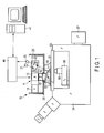
- a scanning probe microscope according to this embodiment is mounted in an inverted optical microscope serving as an optical microscope, as shown in FIG. 1 .
- the inverted optical microscope includes a microscope housing 54, a microscope stage 53, an objective lens 55, a revolver 56, and an epi-illumination light source 57.
- a sample mount 51 such as a slide glass is set on the microscope stage 53, and a sample 50 is held on the sample mount 51.
- the inverted optical microscope is mainly used for in-liquid optical observation of the sample 50.
- the scanning probe microscope is to measure the sample 50 set on the sample mount 51 in liquid.
- the scanning probe microscope includes a probe microscope head 10, a controller 40 to control the probe microscope head 10, and a computer 41 to process information obtained by the probe microscope head 10.
- the probe microscope head 10 is supported above the microscope stage 53 by a column (not shown).
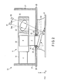
- the probe microscope head 10 includes a scanning mechanism 11 to scan a cantilever chip 1 along the X-, Y-, and Z-axes perpendicular to each other, a support member 21 supporting the scanning mechanism 11, and an optical transmission plate 20 supported by support member 21.
- the scanning mechanism 11 includes a holder 16 to hold the cantilever chip 1, a Z actuator 15 to move the holder 16 along the Z-axis, an X-Y movable portion 12 holding the Z actuator 15, an X actuator 13 to move the X-Y movable portion 12 along the X-axis, and a Y actuator 14 to move the X-Y movable portion 12 along the Y-axis.
- the X actuator 13 and the Y actuator 14 constitute an X-Y scanner to raster-scan the cantilever chip 1 along the X- and Y-axes.
- the X actuator 13, the Y actuator 14, and the Z actuator 15 are constituted by, e.g., multilayer piezoelectric elements.
- the support member 21 has, e.g., a frame shape.
- the scanning mechanism 11 is arranged inside the support member 21, and both the X actuator 13 and the Y actuator 14 are fixed to the support member 21.
- the optical transmission plate 20 is fixed to the lower end of the support member 21, and closes the opening of the frame-shaped support member 21 at the lower end.
- the optical transmission plate 20 is an optically transparent plate and is made of, e.g., glass or resin.
- the support member 21 and the optical transmission plate 20 constitute a housing to contain the scanning mechanism 11.
- the support member 21 and the optical transmission plate 20 are fixed by adhesion or screwing.
- the optical transmission plate 20 is a liquid contact member including an optical transmission portion.
- the optical transmission plate 20 is arranged in contact with liquid on the sample mount 51, so as to cooperate with the sample mount 51 to sandwich the liquid, forming a liquid cell 52 for measuring the sample 50 in an in-liquid environment. That is, the optical transmission plate 20 includes a cell forming portion to form the liquid cell 52 together with the sample mount 51.
- the optical transmission plate 20 has a through hole 22, and the holder 16 extends through the through hole 22.
- the gap between the holder 16 and the through hole 22 is sealed in a waterproof fashion by an elastic member 23.
- Part of the holder 16 and the cantilever chip 1 project into the liquid cell 52 through the through hole 22.
- the elastic member 23 is made of a soft adhesive suitable for waterproofing, such as silicone rubber.
- the liquid cell 52 is a spatial region (environmental region) filled with liquid in order to measure a sample in the liquid. Formation of the liquid cell 52 is to decide the shape of the region of the liquid cell 52. In this embodiment, the shape of the region of the liquid cell 52 is determined by the interface (contact surface) between the liquid and the optical transmission plate 20 (including part of the holder 16 and the cantilever chip 1), the interface (contact surface) between the liquid and the sample mount 51, and the interface (contact surface) between the liquid and air.
- the cantilever chip 1 includes a substrate 2, a cantilever 3 supported by the substrate 2, and a probe 4 provided at the free end of the cantilever 3.
- the cantilever chip 1 is held by the holder 16 of the scanning mechanism 11. More specifically, the substrate 2 is held so that the inclination angle of the substrate 2 with respect to the X-Y plane becomes 5° to 15°, and desirably 10° to 15°.
- the substrate 2 is fixed to the holder 16 by an adhesive such as wax.
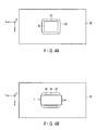
- the cantilever chip 1 is held by the holder 16 so that, for example, the longitudinal direction of the cantilever 3 is along the Y-axis, as shown in FIG. 4B .
- the holder 16 is made of a lightweight hard material such as ceramic or aluminum.
- the holder 16 is formed to be compact so that its volume is triple or less of the volume of the substrate 2, and desirably double or less.
- the volume of the substrate 2 is 1.44 mm 3 .
- the size of the holder 16 is equal to or smaller than 4.32 mm 3 , and desirably equal to or smaller than 2.88 mm 3 .
- the probe microscope head 10 also includes a light source 31 to emit detection light 34a of generally parallel light for detecting the displacement of the cantilever 3, a light converging element 32 to converge the detection light 34a from the light source 31 onto the cantilever 3 and to restore detection light reflected by the cantilever 3 into detection light 34b of generally parallel light, and a multi-segments detector 33 to detect a change of the incident position of the detection light 34b.
- the light source 31, the light converging element 32, and the multi-segments detector 33 constitute a displacement sensor to detect the displacement of the cantilever 3 of the cantilever chip 1.
- This displacement sensor is, e.g., an optical lever type optical displacement sensor widely used in a scanning probe microscope.
- the optical transmission plate 20 which itself is optically transparent, transmits the detection light 34a, 34b for detecting the displacement of the cantilever 3.
- the detection light 34a having passed through the light converging element 32 passes through the optical transmission plate 20 and falls on the cantilever 3.
- the detection light 34b reflected by the cantilever 3 passes through the optical transmission plate 20 and enters the light converging element 32.
- the light source 31 and the multi-segments detector 33 are held by a housing frame (not shown).
- the light converging element 32 which is fixed to the X-Y movable portion 12 of the scanning mechanism 11, is scanned by the scanning mechanism 11 together with the cantilever chip 1.
- the light converging element 32 is constituted by, e.g., a single lens.
- the light converging element 32 has an optical characteristic in which the NA is equal to or higher than 0.4 so that a converged spot diameter on the cantilever 3 is equal to or smaller than several ⁇ m.
- a compact lightweight light converging element having a size suited to high-speed scanning e.g., a diameter of 10 mm or less, and desirably 5 mm or less is used.
- the scanning probe microscope according to this embodiment operates as follows.
- the detection light 34a of generally parallel light emitted by the light source 31 is converged by the light converging element 32, and applied on the cantilever 3 through the optical transmission plate 20, so as to form a converged spot approximately 2 ⁇ m in diameter on the cantilever 3.
- the detection light 34b reflected by the cantilever 3 passes through the optical transmission plate 20 and then the light converging element 32, so as to restore into generally parallel light, and enters the multi-segments detector 33.
- the incident position of the detection light 34b onto the multi-segments detector 33 changes in accordance with the Z displacement of the cantilever 3.
- the multi-segments detector 33 outputs, to the controller 40, a displacement signal reflecting the Z displacement of the cantilever 3.
- the controller 40 supplies a scan signal for raster scanning to the X actuator 13 and the Y actuator 14.
- the X actuator 13 and the Y actuator 14 receive the scan signal from the controller 40, and raster-scan the cantilever chip 1 on the X-Y plane. More specifically, the controller 40 supplies, to the X actuator 13, a high-frequency scanning signal corresponding to the high-speed axis of raster scanning. At the same time, the controller 40 supplies, to the Y actuator 14, a low-frequency scanning signal corresponding to the low-speed axis of raster scanning.
- the X actuator 13 receives the high-frequency scanning signal from the controller 40, and raster-scans the cantilever chip 1 at high speed along the X-axis.
- the Y actuator 14 receives the low-frequency scanning signal from the controller 40, and raster-scans the cantilever chip 1 at low speed along the Y-axis.
- the frequency of the scanning signal output from the controller 40 is equal to or higher than 1 kHz for the high-speed axis (X-axis).
- the controller 40 receives the displacement signal of the cantilever 3 from the multi-segments detector 33, and supplies a corresponding scanning signal to the Z actuator 15.
- the Z actuator 15 receives the scanning signal from the controller 40, and scans the cantilever chip 1 along the Z-axis.
- the computer 41 acquires physical information of the sample 50 based on displacement information of the cantilever 3 and scanning information of the scanning mechanism 11, and displays it on a monitor.
- the holder 16 is scanned by the scanning mechanism 11, while the optical transmission plate 20 serving as a liquid contact member is not scanned by the scanning mechanism 11. That is, the optical transmission plate 20 is not a scanning target object that is scanned by the scanning mechanism 11. More specifically, the optical transmission plate 20 is joined to the fixed end of the X actuator 13 and the fixed end of the Y actuator 14 through the support member 21, but is not joined to their operation ends. The optical transmission plate 20 is also joined through the elastic member 23 to the holder 16 that is scanned by the X actuator 13, the Y actuator 14, and the Z actuator 15. Since the elastic member 23 elastically deforms and absorbs the motion of the holder 16, the optical transmission plate 20 is not scanned by the scanning mechanism 11. This reduces a liquid motion generated at the time of scanning.
- FIG. 5 shows a state in which the X-Y movable portion 12 is scanned in the negative direction along the Y-axis.
- the through hole 22 and the holder 16 come close to each other on the negative side along the Y-axis with reference to the holder 16, and move apart from each other on the positive side along the Y-axis.
- the gap between the through hole 22 and the holder 16 is sealed in a waterproof fashion by the elastic member 23, and the elastic member 23 deforms in accordance with a change of the distance between the through hole 22 and the holder 16, so that waterproofing of the gap between the through hole 22 and the holder 16 is maintained. This can prevent entrance of the liquid into the housing constituted by the support member 21 and the optical transmission plate 20.
- the optical transmission plate 20 is not scanned in any scanning along the X-, Y-, and Z-axes.
- the shape of the liquid cell 52 formed by sandwiching the liquid between the sample mount 51 and the optical transmission plate 20 does not change. That is, the interface between the liquid cell 52 and air does not move. Only part of the holder 16 and the cantilever chip 1 project from the through hole 22 into the liquid. That is, target objects scanned in the liquid of the liquid cell 52 are minimum members, i.e., only the compact holder 16 and the cantilever chip 1.
- the contact area and volume by which the liquid cell and the scanning target object contact each other can be decreased, and vibrations of the liquid generated at the time of scanning can be reduced.
- the scanning probe microscope according to this embodiment reduces partial vibrations and convection of the liquid that are generated at the time of scanning, compared to the scanning mechanism in U.S. Patent No. 8,087,288 . As a result, the scanning probe microscope according to this embodiment enables high-precision observation.
- This AFM aims to obtain one frame within 1 sec, and desirably within 0.1 sec.
- the Y-axis direction is set as the low-speed direction of raster scanning, and an image of 100 pixels in the X-axis direction x 100 pixels in the Y-axis direction is captured in 0.1 sec, the scanning frequency in the X-axis direction becomes 1 kHz, the scanning frequency in the Y-axis direction becomes 10 Hz, and the scanning frequency in the Z-axis direction reaches 100 kHz or higher.
- This speed is 10 to 100 times higher than the speed of the conventional AFM.
- the liquid is viscous, and the magnitude of the viscous resistance increases in proportion to the scanning frequency. If the scanning speed increases, the influence of vibrations of the liquid increases proportionally.
- the cantilever 3 is raster-scanned at high speed along the X-axis and at low speed along the Y-axis. As described above, the cantilever 3 is arranged so that its longitudinal direction is along the Y-axis, as shown in FIG. 6 .
- the viscous resistance of the liquid is readily generated, and the cantilever 3 readily deforms.
- the convection of the liquid also increases.
- the magnitude of the viscous resistance is proportional to the scanning frequency.
- the magnitude of the viscous resistance generated at the time of scanning along the Y-axis serving as the longitudinal direction of the cantilever 3 is proportional to the product of an area Sy of the lever surface of the cantilever 3 projected onto the X-Z plane, and a scanning frequency fy.
- the magnitude of the viscous resistance generated at the time of scanning along the X-axis is proportional to the product of an area Sx of the side surface of the cantilever 3 projected onto the Y-Z plane, and a scanning frequency fx.
- the cantilever 3 is held at an angle of 12° with respect to the sample surface, the length of the cantilever 3 is 10 ⁇ m, the width of the proximal end is 4 ⁇ m, and the thickness is 0.1 ⁇ m (general values of the dimensions of a cantilever used for high-speed observation in liquid).
- the area Sy is four times larger than the area Sx.
- the magnitude of the viscous resistance generated at the time of scanning in the longitudinal direction (Y-axis direction) of the cantilever 3 is four times larger, compared to scanning along the X-axis.
- the cantilever 3 has a shape that is readily deformed by a force along the Y-axis, and is hardly deformed by a force along the X-axis.
- the deformation amount of the cantilever 3 generated at the time of scanning in the longitudinal direction (Y-axis direction) of the cantilever 3 is much more than 4 times, compared to scanning along the X-axis.
- the holder 16 holds the cantilever chip 1 so that the longitudinal direction of the cantilever 3 coincides with the low-speed Y-axis direction.
- the influence of the viscous resistance of the liquid is suppressed to be small, and higher-precision scanning becomes possible.
- the AFM capable of high-speed scanning to observe the motion of a biological sample, since the scanning frequency in the X-axis direction reaches 1 kHz, the AFM has a problem that the influence of the viscous resistance of liquid becomes especially serious.
- the scanning probe microscope can reduce vibrations of liquid generated at the time of scanning and is effective particularly when high-speed scanning is necessary.
- the optical transmission plate 20 is directly fixed to the support member 21 supporting the scanning mechanism 11 in this embodiment, but may be indirectly fixed to the support member 21 through another member.
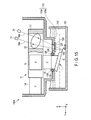
- FIG. 8 shows a scanning probe microscope according to this embodiment.
- FIGS. 9 , 10A, and 10B show a probe microscope head.
- the same reference numerals as those in FIGS. 1 , 2 , 4A, and 4B denote the same parts, and a detailed description thereof will not be repeated.
- the scanning probe microscope according to this embodiment is different in the probe microscope head from the scanning probe microscope according to the first embodiment.
- a probe microscope head 10A according to this embodiment is different from the probe microscope head 10 according to the first embodiment in a housing to contain a scanning mechanism 11.
- the housing to contain the scanning mechanism 11 is constituted by a basic housing 25 and an optical transmission plate 29.
- the probe microscope head 10A according to this embodiment is constituted by replacing the support member 21 and optical transmission plate 20 of the probe microscope head 10 according to the first embodiment with the basic housing 25 and the optical transmission plate 29.
- the basic housing 25 is constituted by a peripheral wall portion 25a surrounding the scanning mechanism 11, and a bottom portion 25b closing the lower end of the peripheral wall portion 25a.
- the bottom portion 25b has a through hole 26, and a holder 16 extends through the through hole 26.
- the gap between the holder 16 and the through hole 26 is sealed in a waterproof fashion by an elastic member 28.
- Part of the holder 16 and a cantilever chip 1 project into a liquid cell 52 through the through hole 26.
- the elastic member 28 is made of a soft adhesive suitable for waterproofing, such as silicone rubber.
- the bottom portion 25b of the basic housing 25 has another through hole 27.
- the optical transmission plate 29 is an optically transparent plate made of glass or resin, and closes the through hole 27.
- the optical transmission plate 29 is adhered and fixed to the bottom portion 25b so as to maintain waterproofing.
- the through hole 27 and the optical transmission plate 29 constitute an optical transmission portion to transmit detection light 34a, 34b for detecting the displacement of the cantilever 3.
- the bottom portion 25b and the optical transmission plate 29 constitute a liquid contact member including an optical transmission portion.
- the bottom portion 25b and the optical transmission plate 29 are arranged in contact with liquid on the sample mount 51, so as to cooperate with the sample mount 51 to sandwich the liquid, forming the liquid cell 52 for measuring a sample 50 in an in-liquid environment. That is, the bottom portion 25b and the optical transmission plate 29 include a cell forming portion to form the liquid cell 52 together with the sample mount 51.
- the shape of the region of the liquid cell 52 is determined by the interface (contact surface) between the liquid and the liquid contact member (including part of the holder 16 and the cantilever chip 1) constituted by the bottom portion 25b and the optical transmission plate 29, the interface (contact surface) between the sample mount 51 and the liquid, and the interface between air and the liquid.
- the holder 16 holds the cantilever chip 1 so that, for example, the longitudinal direction of the cantilever 3 is along the Y-axis, as shown in FIG. 10B .
- the scanning probe microscope having the above arrangement according to this embodiment has the same advantages as those of the scanning probe microscope according to the first embodiment, and also has the following advantages.
- the optical transmission plate 20 in the probe microscope head 10 according to the first embodiment is made of, e. g. , glass or resin.
- the glass is fragile (chips easily).
- the resin readily causes aged deterioration. The influence of these factors becomes more serious as the size (area) of the optical transmission plate 20 becomes larger.
- the probe microscope head 10A according to this embodiment since the area of the optical transmission plate 29 is small, the above-mentioned influence can be reduced.
- the member to form the liquid cell together with the sample mount 51 is constituted by part of the basic housing 25, that is, the bottom portion 25b.
- this member may be constituted by a member not scanned by the scanning mechanism 11, e.g., a plate-like member fixed to the basic housing 25.
- a scanning probe microscope according to this embodiment is mounted in an inverted optical microscope serving as an optical microscope, as shown in FIG. 11 .
- the inverted optical microscope includes a microscope housing 54, a microscope stage 53, an objective lens 55, a revolver 56, and an epi-illumination light source 57.
- a sample mount 151 such as a dish is set on the microscope stage 53, and a sample 150 is held on the sample mount 151.
- the inverted optical microscope is mainly used for in-liquid optical observation of the sample 150.
- the scanning probe microscope is to measure the sample 150 set on the sample mount 151 in liquid.
- the scanning probe microscope includes a probe microscope head 100, a controller 40 to control the probe microscope head 100, and a computer 41 to process information obtained by the probe microscope head 100.
- the probe microscope head 100 is supported above the microscope stage 53 by a column (not shown).
- the probe microscope head 100 includes a scanning mechanism 11 to scan a cantilever chip 1 along the X-, Y-, and Z-axes perpendicular to each other, a support member 121 supporting the scanning mechanism 11, and an optical transmission plate 120 supported by the support member 121.
- the scanning mechanism 11 includes a holder 16 to hold the cantilever chip 1, a Z actuator 15 to move the holder 16 along the Z-axis, an X-Y movable portion 12 holding the Z actuator 15, an X actuator 13 to move the X-Y movable portion 12 along the X-axis, and a Y actuator 14 to move the X-Y movable portion 12 along the Y-axis.
- the X actuator 13 and the Y actuator 14 constitute an X-Y scanner to raster-scan the cantilever chip 1 along the X- and Y-axes.
- the X actuator 13, the Y actuator 14, and the Z actuator 15 are constituted by, e.g., multilayer piezoelectric elements.
- the support member 121 has, e.g. , a shape in which a convex is reversed, which may be referred as a reverse convex shape below.
- the scanning mechanism 11 is arranged inside the support member 121, and both the X actuator 13 and the Y actuator 14 are fixed to the support member 121.
- the optical transmission plate 120 is fixed to the lower end of the support member 121, and closes the opening at the lower end of the support member 121 in reverse convex shape.
- the optical transmission plate 120 is an optically transparent plate and is made of, e.g., glass or resin.
- the support member 121 and the optical transmission plate 120 constitute a housing to contain the scanning mechanism 11.
- the support member 121 and the optical transmission plate 120 are fixed by adhesion or screwing.
- the optical transmission plate 120 is a liquid contact member including an optical transmission portion.
- the optical transmission plate 120 is arranged in contact with liquid on the sample mount 151, so as to cooperate with the sample mount 151 to sandwich the liquid, forming a liquid cell 152 for measuring the sample 150 in an in-liquid environment. That is, the optical transmission plate 120 includes a cell forming portion to form the liquid cell 152 together with the sample mount 151.
- the optical transmission plate 120 has a through hole 122, and the holder 16 extends through the through hole 122.
- the gap between the holder 16 and the through hole 122 is sealed in a waterproof fashion by an elastic member 123.
- Part of the holder 16 and the cantilever chip 1 project into the liquid cell 152 through the through hole 122.
- the elastic member 123 is made of a soft adhesive suitable for waterproofing, such as silicone rubber.
- the liquid cell 152 is a spatial region (environmental region) filled with liquid in order to measure a sample in the liquid. Formation of the liquid cell 152 is to decide the shape of the region of the liquid cell 152. In this embodiment, the shape of the region of the liquid cell 152 is determined by the interface (contact surface) between the liquid and the optical transmission plate 120 (including part of the holder 16 and the cantilever chip 1), the interface (contact surface) between the liquid and the sample mount 151, and the interface (contact surface) between the liquid and air.
- the cantilever chip 1 includes a substrate 2, a cantilever 3 supported by the substrate 2, and a probe 4 provided at the free end of the cantilever 3.
- the cantilever chip 1 is held by the holder 16 of the scanning mechanism 11. More specifically, the substrate 2 is held so that the inclination angle of the substrate 2 with respect to the X-Y plane becomes 5° to 15°, and desirably 10° to 15°.
- the substrate 2 is fixed to the holder 16 by an adhesive such as wax.
- the cantilever chip 1 is held by the holder 16 so that, for example, the longitudinal direction of the cantilever 3 is along the Y-axis, as shown in FIG. 13B .
- the holder 16 is made of a lightweight hard material such as ceramic or aluminum.
- the holder 16 is formed to be compact so that its volume is triple or less of the volume of the substrate 2, and desirably double or less.
- the volume of the substrate 2 is 1.44 mm 3 .
- the size of the holder 16 is equal to or smaller than 4.32 mm 3 , and desirably equal to or smaller than 2.88 mm 3 .
- the probe microscope head 100 also includes a light source 31 to emit detection light 34a of generally parallel light for detecting the displacement of the cantilever 3, a light converging element 32 to converge the detection light 34a from the light source 31 onto the cantilever 3 and to restore detection light reflected by the cantilever 3 into detection light 34b of generally parallel light, and a multi-segments detector 33 to detect a change of the incident position of the detection light 34b.
- the light source 31, the light converging element 32, and the multi-segments detector 33 constitute a displacement sensor to detect the displacement of the cantilever 3 of the cantilever chip 1.
- This displacement sensor is, e.g., an optical lever type optical displacement sensor widely used in a scanning probe microscope.
- the optical transmission plate 120 which itself is optically transparent, transmits the detection light 34a, 34b for detecting the displacement of the cantilever 3.
- the detection light 34a having passed through the light converging element 32 passes through the optical transmission plate 120 and falls on the cantilever 3.
- the detection light 34b reflected by the cantilever 3 passes through the optical transmission plate 120 and enters the light converging element 32.
- the light source 31 and the multi-segments detector 33 are held by a housing frame (not shown).
- the light converging element 32 which is fixed to the X-Y movable portion 12 of the scanning mechanism 11, is scanned by the scanning mechanism 11 together with the cantilever chip 1.
- the light converging element 32 is constituted by, e.g., a single lens.
- the light converging element 32 has an optical characteristic in which the NA is equal to or higher than 0.4 so that a converged spot diameter on the cantilever 3 is equal to or smaller than several ⁇ m.
- a compact lightweight light converging element having a size suited to high-speed scanning e.g., a diameter of 10 mm or less, and desirably 5 mm or less is used.
- the scanning probe microscope according to this embodiment operates as follows.
- the detection light 34a of generally parallel light emitted by the light source 31 is converged by the light converging element 32, and applied on the cantilever 3 through the optical transmission plate 120, so as to form a converged spot approximately 2 ⁇ m in diameter on the cantilever 3.
- the detection light 34b reflected by the cantilever 3 passes through the optical transmission plate 120 and then the light converging element 32, so as to restore into generally parallel light, and enters the multi-segments detector 33.
- the incident position of the detection light 34b onto the multi-segments detector 33 changes in accordance with the Z displacement of the cantilever 3.
- the multi-segments detector 33 outputs, to the controller 40, a displacement signal reflecting the Z displacement of the cantilever 3.
- the controller 40 supplies a scan signal for raster scanning to the X actuator 13 and the Y actuator 14.
- the X actuator 13 and the Y actuator 14 receive the scan signal from the controller 40, and raster-scan the cantilever chip 1 on the X-Y plane. More specifically, the controller 40 supplies, to the X actuator 13, a high-frequency scanning signal corresponding to the high-speed axis of raster scanning. At the same time, the controller 40 supplies, to the Y actuator 14, a low-frequency scanning signal corresponding to the low-speed axis of raster scanning.
- the X actuator 13 receives the high-frequency scanning signal from the controller 40, and raster-scans the cantilever chip 1 at high speed along the X-axis.
- the Y actuator 14 receives the low-frequency scanning signal from the controller 40, and raster-scans the cantilever chip 1 at low speed along the Y-axis.
- the frequency of the scanning signal output from the controller 40 is equal to or higher than 1 kHz for the high-speed axis (X-axis).
- the controller 40 receives the displacement signal of the cantilever 3 from the multi-segments detector 33, and supplies a corresponding scanning signal to the Z actuator 15.
- the Z actuator 15 receives the scanning signal from the controller 40, and scans the cantilever chip 1 along the Z-axis.
- the computer 41 acquires physical information of the sample 150 based on displacement information of the cantilever 3 and scanning information of the scanning mechanism 11, and displays it on a monitor.
- the holder 16 is scanned by the scanning mechanism 11, while the optical transmission plate 120 serving as a liquid contact member is not scanned by the scanning mechanism 11. That is, the optical transmission plate 120 is not a scanning target object that is scanned by the scanning mechanism 11. More specifically, the optical transmission plate 120 is joined to the fixed end of the X actuator 13 and the fixed end of the Y actuator 14 through the support member 121, but is not joined to their operation ends. The optical transmission plate 120 is also joined through the elastic member 123 to the holder 16 that is scanned by the X actuator 13, the Y actuator 14, and the Z actuator 15. Since the elastic member 123 elastically deforms and absorbs the motion of the holder 16, the optical transmission plate 120 is not scanned by the scanning mechanism 11. This reduces a liquid motion generated at the time of scanning.
- the gap between the through hole 122 and the holder 16 is sealed in a waterproof fashion by the elastic member 123, and the elastic member 123 deforms in accordance with a change of the distance between the through hole 122 and the holder 16, so that waterproofing of the gap between the through hole 122 and the holder 16 is maintained. This can prevent entrance of the liquid into the housing constituted by the support member 121 and the optical transmission plate 120.
- the optical transmission plate 120 is not scanned in any scanning along the X-, Y-, and Z-axes.
- the shape of the liquid cell 152 formed by sandwiching the liquid between the sample mount 151 and the optical transmission plate 120 does not change. That is, the interface between the liquid cell 152 and air does not move. Only part of the holder 16 and the cantilever chip 1 project from the through hole 122 into the liquid. That is, target objects scanned in the liquid of the liquid cell 152 are minimum members, i.e., only the compact holder 16 and the cantilever chip 1.
- the contact area and volume by which the liquid cell and the scanning target object contact each other can be decreased, and vibrations of the liquid generated at the time of scanning can be reduced.
- the scanning probe microscope according to this embodiment reduces partial vibrations and convection of the liquid that are generated at the time of scanning, compared to the scanning mechanism in U.S. Patent No. 8,087,288 . As a result, the scanning probe microscope according to this embodiment enables high-precision observation.
- This AFM aims to obtain one frame within 1 sec, and desirably within 0.1 sec.
- the Y-axis direction is set as the low-speed direction of raster scanning, and an image of 100 pixels in the X-axis direction ⁇ 100 pixels in the Y-axis direction is captured in 0.1 sec, the scanning frequency in the X-axis direction becomes 1 kHz, the scanning frequency in the Y-axis direction becomes 10 Hz, and the scanning frequency in the Z-axis direction reaches 100 kHz or higher.
- This speed is 10 to 100 times higher than the speed of the conventional AFM.
- the liquid is viscous, and the magnitude of the viscous resistance increases in proportion to the scanning frequency. If the scanning speed increases, the influence of vibrations of the liquid increases proportionally.
- the cantilever 3 is raster-scanned at high speed along the X-axis and at low speed along the Y-axis. As described above, the cantilever 3 is arranged so that its longitudinal direction is along the Y-axis, as shown in FIG. 6 .
- the viscous resistance of the liquid is readily generated, and the cantilever 3 readily deforms.
- the convection of the liquid also increases.
- the magnitude of the viscous resistance is proportional to the scanning frequency.
- the magnitude of the viscous resistance generated at the time of scanning along the Y-axis serving as the longitudinal direction of the cantilever 3 is proportional to the product of an area Sy of the lever surface of the cantilever 3 projected onto the X-Z plane, and a scanning frequency fy.
- the magnitude of the viscous resistance generated at the time of scanning along the X-axis is proportional to the product of an area Sx of the side surface of the cantilever 3 projected onto the Y-Z plane, and a scanning frequency fx.
- the cantilever 3 is held at an angle of 12° with respect to the sample surface, the length of the cantilever 3 is 10 ⁇ m, the width of the proximal end is 4 ⁇ m, and the thickness is 0. 1 ⁇ m (general values of the dimensions of a cantilever used for high-speed observation in liquid).
- the area Sy is four times larger than the area Sx.
- the magnitude of the viscous resistance generated at the time of scanning in the longitudinal direction (Y-axis direction) of the cantilever 3 is four times larger, compared to scanning along the X-axis.
- the cantilever 3 has a shape that is readily deformed by a force along the Y-axis, and is hardly deformed by a force along the X-axis.
- the deformation amount of the cantilever 3 generated at the time of scanning in the longitudinal direction (Y-axis direction) of the cantilever 3 is much more than 4 times, compared to scanning along the X-axis.
- the holder 16 holds the cantilever chip 1 so that the longitudinal direction of the cantilever 3 coincides with the low-speed Y-axis direction.
- the influence of the viscous resistance of the liquid is suppressed to be small, and higher-precision scanning becomes possible.
- the AFM capable of high-speed scanning to observe the motion of a biological sample, since the scanning frequency in the X-axis direction reaches 1 kHz, the AFM has a problem that the influence of the viscous resistance of liquid becomes especially serious.
- the scanning probe microscope can reduce vibrations of liquid generated at the time of scanning and is effective particularly when high-speed scanning is necessary.
- the optical transmission plate 120 is directly fixed to the support member 121 supporting the scanning mechanism 11 in this embodiment, but may be indirectly fixed to the support member 121 through another member.
- FIG. 14 shows a scanning probe microscope according to this embodiment.
- FIGS. 15 , 16A, and 16B show a probe microscope head.
- the same reference numerals as those in FIGS. 11 , 12 , 13A, and 13B denote the same parts, and a detailed description thereof will not be repeated.
- the scanning probe microscope according to this embodiment is different in the probe microscope head from the scanning probe microscope according to the first embodiment.
- a probe microscope head 100A according to this embodiment is different from the probe microscope head 100 according to the first embodiment in a housing to contain a scanning mechanism 11.
- the housing to contain the scanning mechanism 11 is constituted by a basic housing 125 and an optical transmission plate 129.
- the probe microscope head 100A according to this embodiment is constituted by replacing the support member 121 and optical transmission plate 120 of the probe microscope head 100 according to the first embodiment with the basic housing 125 and the optical transmission plate 129.
- the basic housing 125 is constituted by a peripheral wall portion 125a surrounding the scanning mechanism 11, and a bottom portion 125b closing the lower end of the peripheral wall portion 125a.
- the bottom portion 125b has a through hole 126, and a holder 16 extends through the through hole 126.
- the gap between the holder 16 and the through hole 126 is sealed in a waterproof fashion by an elastic member 128.
- Part of the holder 16 and a cantilever chip 1 project into a liquid cell 152 through the through hole 126.
- the elastic member 128 is made of a soft adhesive suitable for waterproofing, such as silicone rubber.
- the bottom portion 125b of the basic housing 125 has another through hole 127.
- the optical transmission plate 129 is an optically transparent plate made of glass or resin, and closes the through hole 127.
- the optical transmission plate 129 is adhered and fixed to the bottom portion 125b so as to maintain waterproofing.
- the through hole 127 and the optical transmission plate 129 constitute an optical transmission portion to transmit detection light 34a, 34b for detecting the displacement of the cantilever 3.
- the bottom portion 125b and the optical transmission plate 129 constitute a liquid contact member including an optical transmission portion.
- the bottom portion 125b and the optical transmission plate 129 are arranged in contact with liquid on the sample mount 151, so as to cooperate with the sample mount 151 to sandwich the liquid, forming the liquid cell 152 for measuring a sample 150 in an in-liquid environment. That is, the bottom portion 125b and the optical transmission plate 129 include a cell forming portion to form the liquid cell 152 together with the sample mount 151.
- the shape of the region of the liquid cell 152 is determined by the interface (contact surface) between the liquid and the liquid contact member (including part of the holder 16 and the cantilever chip 1) constituted by the bottom portion 125b and the optical transmission plate 129, the interface (contact surface) between the sample mount 151 and the liquid, and the interface between air and the liquid.
- the holder 16 holds the cantilever chip 1 so that, for example, the longitudinal direction of the cantilever 3 is along the Y-axis, as shown in FIG. 16B .
- the scanning probe microscope having the above arrangement according to this embodiment has the same advantages as those of the scanning probe microscope according to the first embodiment, and also has the following advantages.
- the optical transmission plate 120 in the probe microscope head 100 according to the first embodiment is made of, e.g., glass or resin.
- the glass is fragile (chips easily).
- the resin readily causes aged deterioration. The influence of these factors becomes more serious as the size (area) of the optical transmission plate 120 becomes larger.
- the probe microscope head 100A according to this embodiment since the area of the optical transmission plate 129 is small, the above-mentioned influence can be reduced.
- the member to form the liquid cell together with the sample mount 151 is constituted by part of the basic housing 125, that is, the bottom portion 125b.
- this member may be constituted by a member not scanned by the scanning mechanism 11, e.g., a plate-like member fixed to the basic housing 125.
- the displacement sensor of the cantilever 3 is constituted by an optical lever type optical displacement sensor.
- a self detection type cantilever in which a piezoresistive element is mounted on the cantilever 3 to detect the displacement of the cantilever 3 by itself may be used.
Landscapes
- Physics & Mathematics (AREA)
- Health & Medical Sciences (AREA)
- General Health & Medical Sciences (AREA)
- General Physics & Mathematics (AREA)
- Nuclear Medicine, Radiotherapy & Molecular Imaging (AREA)
- Radiology & Medical Imaging (AREA)
- Length Measuring Devices With Unspecified Measuring Means (AREA)
Abstract
Description
- The present invention relates to a scanning mechanism of a scanning probe microscope.
- A scanning probe microscope (SPM) is a scanning microscope that mechanically scans a mechanical probe by a scanning mechanism to obtain information of a sample surface. The scanning probe microscope is a generic term for a scanning tunneling microscope (STM), an atomic force microscope (AFM), a scanning magnetic force microscope (MFM), a scanning near field optical microscope (SNOM), and the like. The scanning probe microscope raster-scans the mechanical probe and a sample relatively in the X and Y directions to obtain surface information of a desired sample region through the mechanical probe, and map and display it on a monitor TV.
- Above all, the AFM is a most popular apparatus, and includes, as main machine mechanisms, a cantilever having a mechanical probe at its free end, an optical displacement sensor to detect the displacement of the cantilever, and a scanning mechanism to relatively scan the mechanical probe and a sample. As the optical displacement sensor, an optical lever type optical displacement sensor is employed most widely because of its simple arrangement and high displacement detection sensitivity. The optical lever type optical displacement sensor applies a beam having a diameter of several µm to several ten µm to a cantilever. A change in the reflection direction of the reflected beam depending on the warp of the lever is detected by a two-segments detector or the like. The operation of the mechanical probe at the free end of the cantilever is detected and output as an electrical signal. While the scanning mechanism is controlled in the Z axis direction to keep this output constant, the scanning mechanism is similarly scanned in the X and Y axes directions to map and display the uneven state of a sample surface on the monitor of a computer.
- When observing a biological sample in liquid, the AFM is generally combined with an inverted optical microscope. This is because the inverted optical microscope observation is effective not only when obtaining the finding of a sample, but also when positioning the cantilever at a specific portion of the sample. For such a purpose, a lever scan type AFM to scan the cantilever in the X, Y, and Z axes directions is often used so as to cope with various biological samples and sample substrates.
- A related art of a lever scan type AFM that is used in liquid is disclosed in
U.S. Patent No. 8,087,288 . - Patent Literature 1:
U.S. Patent No. 8,087,288 - In the AFM of the related art, an optical member to form a liquid cell is scanned in X, Y, and Z. At the time of scanning, the shape of the liquid cell, in other words, the interface between the liquid and air is moved in X, Y, and Z. Further, partial vibrations and convection of the liquid that are generated inside the liquid cell increase. Since the liquid is viscous, these liquid motions transfer to various locations such as a sample mount on which a sample is mounted, and affect them as vibration noise that decreases the measurement precision of the AFM. This is a serious problem to the AFM, of which high precision observation is requested.
- The present invention has been made in consideration of the above situation, and has as its object to provide a scanning probe microscope in which liquid motions generated at the time of scanning are reduced.
- The present invention is directed to a scanning probe microscope to measure a sample set on a sample mount in liquid, the scanning probe microscope comprising a scanning mechanism to scan a cantilever provided with a probe at a free end along an X-axis, a Y-axis, and a Z-axis perpendicular to each other, and a liquid contact member including an optical transmission portion to transmit detection light for detecting a displacement of the cantilever, and arranged at least partially in contact with the liquid. The liquid contact member is not scanned by the scanning mechanism.
- The present invention provides a scanning probe microscope in which liquid motions generated at the time of scanning are reduced.
-
-
FIG. 1 shows a scanning probe microscope according to a first embodiment. -
FIG. 2 is an enlarged view showing a probe microscope head shown inFIG. 1 . -
FIG. 3A is a plan view showing a cantilever chip shown inFIGS. 1 and2 . -
FIG. 3B is a side view showing the cantilever chip shown inFIGS. 1 and2 . -
FIG. 3C is a bottom view showing the cantilever chip shown inFIGS. 1 and2 . -
FIG. 4A is a view showing the probe microscope head inFIG. 2 in a state in which the cantilever chip is removed from a holder, when viewed from a liquid cell. -
FIG. 4B is a view showing the probe microscope head inFIG. 2 in a state in which the cantilever chip is fixed to the holder, when viewed from the liquid cell. -
FIG. 5 shows a state in which an X-Y movable portion is scanned in the negative direction along the Y-axis. -
FIG. 6 shows the arrangement relationship between the longitudinal direction of the cantilever and the scanning axis. -
FIG. 7A shows the deformation of the cantilever generated when the cantilever is scanned in its longitudinal direction. -
FIG. 7B shows the deformation of the cantilever generated when the cantilever is scanned in its longitudinal direction. -
FIG. 8 shows a scanning probe microscope according to a second embodiment. -
FIG. 9 is an enlarged view showing a probe microscope head shown inFIG. 8 . -
FIG. 10A is a view showing the probe microscope head inFIG. 8 in a state in which a cantilever chip is removed from a holder, when viewed from a liquid cell. -
FIG. 10B is a view showing the probe microscope head inFIG. 8 in a state in which the cantilever chip is fixed to the holder, when viewed from the liquid cell. -
FIG. 11 shows a scanning probe microscope according to a third embodiment. -
FIG. 12 is an enlarged view showing a probe microscope head shown inFIG. 11 . -
FIG. 13A is a view showing the probe microscope head inFIG. 11 in a state in which a cantilever chip is removed from a holder, when viewed from a liquid cell. -
FIG. 13B is a view showing the probe microscope head inFIG. 11 in a state in which the cantilever chip is fixed to the holder, when viewed from the liquid cell. -
FIG. 14 shows a scanning probe microscope according to a fourth embodiment. -
FIG. 15 is an enlarged view showing a probe microscope head shown inFIG. 14 . -
FIG. 16A is a view showing the probe microscope head inFIG. 14 in a state in which a cantilever chip is removed from a holder, when viewed from a liquid cell. -
FIG. 16B is a view showing the probe microscope head inFIG. 14 in a state in which the cantilever chip is fixed to the holder, when viewed from the liquid cell. - Embodiments will now be described with reference to the accompanying drawings.
- A scanning probe microscope according to this embodiment is mounted in an inverted optical microscope serving as an optical microscope, as shown in
FIG. 1 . - The inverted optical microscope includes a
microscope housing 54, amicroscope stage 53, anobjective lens 55, arevolver 56, and an epi-illumination light source 57. Asample mount 51 such as a slide glass is set on themicroscope stage 53, and asample 50 is held on thesample mount 51. The inverted optical microscope is mainly used for in-liquid optical observation of thesample 50. - The scanning probe microscope according to this embodiment is to measure the
sample 50 set on thesample mount 51 in liquid. The scanning probe microscope includes aprobe microscope head 10, acontroller 40 to control theprobe microscope head 10, and acomputer 41 to process information obtained by theprobe microscope head 10. Theprobe microscope head 10 is supported above themicroscope stage 53 by a column (not shown). - As shown in
FIG. 2 , theprobe microscope head 10 includes ascanning mechanism 11 to scan acantilever chip 1 along the X-, Y-, and Z-axes perpendicular to each other, asupport member 21 supporting thescanning mechanism 11, and anoptical transmission plate 20 supported bysupport member 21. - The
scanning mechanism 11 includes aholder 16 to hold thecantilever chip 1, aZ actuator 15 to move theholder 16 along the Z-axis, an X-Ymovable portion 12 holding theZ actuator 15, anX actuator 13 to move the X-Ymovable portion 12 along the X-axis, and aY actuator 14 to move the X-Ymovable portion 12 along the Y-axis. TheX actuator 13 and theY actuator 14 constitute an X-Y scanner to raster-scan thecantilever chip 1 along the X- and Y-axes. TheX actuator 13, theY actuator 14, and theZ actuator 15 are constituted by, e.g., multilayer piezoelectric elements. - The
support member 21 has, e.g., a frame shape. Thescanning mechanism 11 is arranged inside thesupport member 21, and both theX actuator 13 and theY actuator 14 are fixed to thesupport member 21. - The
optical transmission plate 20 is fixed to the lower end of thesupport member 21, and closes the opening of the frame-shapedsupport member 21 at the lower end. Theoptical transmission plate 20 is an optically transparent plate and is made of, e.g., glass or resin. Thesupport member 21 and theoptical transmission plate 20 constitute a housing to contain thescanning mechanism 11. Thesupport member 21 and theoptical transmission plate 20 are fixed by adhesion or screwing. - The
optical transmission plate 20 is a liquid contact member including an optical transmission portion. Theoptical transmission plate 20 is arranged in contact with liquid on thesample mount 51, so as to cooperate with thesample mount 51 to sandwich the liquid, forming aliquid cell 52 for measuring thesample 50 in an in-liquid environment. That is, theoptical transmission plate 20 includes a cell forming portion to form theliquid cell 52 together with thesample mount 51. - The
optical transmission plate 20 has a throughhole 22, and theholder 16 extends through the throughhole 22. The gap between theholder 16 and the throughhole 22 is sealed in a waterproof fashion by anelastic member 23. Part of theholder 16 and thecantilever chip 1 project into theliquid cell 52 through the throughhole 22. Theelastic member 23 is made of a soft adhesive suitable for waterproofing, such as silicone rubber. Although part of theholder 16 projects into theliquid cell 52 inFIG. 2 , theentire holder 16 may project into theliquid cell 52. - In this specification, the
liquid cell 52 is a spatial region (environmental region) filled with liquid in order to measure a sample in the liquid. Formation of theliquid cell 52 is to decide the shape of the region of theliquid cell 52. In this embodiment, the shape of the region of theliquid cell 52 is determined by the interface (contact surface) between the liquid and the optical transmission plate 20 (including part of theholder 16 and the cantilever chip 1), the interface (contact surface) between the liquid and thesample mount 51, and the interface (contact surface) between the liquid and air. - As shown in
FIGS. 3A, 3B, and 3C , thecantilever chip 1 includes asubstrate 2, acantilever 3 supported by thesubstrate 2, and aprobe 4 provided at the free end of thecantilever 3. Thecantilever chip 1 is held by theholder 16 of thescanning mechanism 11. More specifically, thesubstrate 2 is held so that the inclination angle of thesubstrate 2 with respect to the X-Y plane becomes 5° to 15°, and desirably 10° to 15°. Thesubstrate 2 is fixed to theholder 16 by an adhesive such as wax. - The
cantilever chip 1 is held by theholder 16 so that, for example, the longitudinal direction of thecantilever 3 is along the Y-axis, as shown inFIG. 4B . - The
holder 16 is made of a lightweight hard material such as ceramic or aluminum. Theholder 16 is formed to be compact so that its volume is triple or less of the volume of thesubstrate 2, and desirably double or less. For example, when the dimensions of thesubstrate 2 are 3 mm × 1.6 mm × 0.3 mm (currently available standard size), the volume of thesubstrate 2 is 1.44 mm3. In this case, the size of theholder 16 is equal to or smaller than 4.32 mm3, and desirably equal to or smaller than 2.88 mm3. - Referring again to
FIG. 2 , theprobe microscope head 10 also includes alight source 31 to emitdetection light 34a of generally parallel light for detecting the displacement of thecantilever 3, alight converging element 32 to converge thedetection light 34a from thelight source 31 onto thecantilever 3 and to restore detection light reflected by thecantilever 3 into detection light 34b of generally parallel light, and amulti-segments detector 33 to detect a change of the incident position of thedetection light 34b. Thelight source 31, thelight converging element 32, and themulti-segments detector 33 constitute a displacement sensor to detect the displacement of thecantilever 3 of thecantilever chip 1. This displacement sensor is, e.g., an optical lever type optical displacement sensor widely used in a scanning probe microscope. - The
optical transmission plate 20, which itself is optically transparent, transmits thedetection light cantilever 3. Thedetection light 34a having passed through thelight converging element 32 passes through theoptical transmission plate 20 and falls on thecantilever 3. Thedetection light 34b reflected by thecantilever 3 passes through theoptical transmission plate 20 and enters thelight converging element 32. - The
light source 31 and themulti-segments detector 33 are held by a housing frame (not shown). Thelight converging element 32, which is fixed to the X-Ymovable portion 12 of thescanning mechanism 11, is scanned by thescanning mechanism 11 together with thecantilever chip 1. Thelight converging element 32 is constituted by, e.g., a single lens. Thelight converging element 32 has an optical characteristic in which the NA is equal to or higher than 0.4 so that a converged spot diameter on thecantilever 3 is equal to or smaller than several µm. As thelight converging element 32, a compact lightweight light converging element having a size suited to high-speed scanning, e.g., a diameter of 10 mm or less, and desirably 5 mm or less is used. - The scanning probe microscope according to this embodiment operates as follows.
- The
detection light 34a of generally parallel light emitted by thelight source 31 is converged by thelight converging element 32, and applied on thecantilever 3 through theoptical transmission plate 20, so as to form a converged spot approximately 2 µm in diameter on thecantilever 3. - The
detection light 34b reflected by thecantilever 3 passes through theoptical transmission plate 20 and then thelight converging element 32, so as to restore into generally parallel light, and enters themulti-segments detector 33. The incident position of thedetection light 34b onto themulti-segments detector 33 changes in accordance with the Z displacement of thecantilever 3. Themulti-segments detector 33 outputs, to thecontroller 40, a displacement signal reflecting the Z displacement of thecantilever 3. - The
controller 40 supplies a scan signal for raster scanning to theX actuator 13 and theY actuator 14. TheX actuator 13 and theY actuator 14 receive the scan signal from thecontroller 40, and raster-scan thecantilever chip 1 on the X-Y plane. More specifically, thecontroller 40 supplies, to theX actuator 13, a high-frequency scanning signal corresponding to the high-speed axis of raster scanning. At the same time, thecontroller 40 supplies, to theY actuator 14, a low-frequency scanning signal corresponding to the low-speed axis of raster scanning. TheX actuator 13 receives the high-frequency scanning signal from thecontroller 40, and raster-scans thecantilever chip 1 at high speed along the X-axis. TheY actuator 14 receives the low-frequency scanning signal from thecontroller 40, and raster-scans thecantilever chip 1 at low speed along the Y-axis. The frequency of the scanning signal output from thecontroller 40 is equal to or higher than 1 kHz for the high-speed axis (X-axis). - The
controller 40 receives the displacement signal of thecantilever 3 from themulti-segments detector 33, and supplies a corresponding scanning signal to theZ actuator 15. TheZ actuator 15 receives the scanning signal from thecontroller 40, and scans thecantilever chip 1 along the Z-axis. - The
computer 41 acquires physical information of thesample 50 based on displacement information of thecantilever 3 and scanning information of thescanning mechanism 11, and displays it on a monitor. - In the scanning probe microscope according to this embodiment, the
holder 16 is scanned by thescanning mechanism 11, while theoptical transmission plate 20 serving as a liquid contact member is not scanned by thescanning mechanism 11. That is, theoptical transmission plate 20 is not a scanning target object that is scanned by thescanning mechanism 11. More specifically, theoptical transmission plate 20 is joined to the fixed end of theX actuator 13 and the fixed end of theY actuator 14 through thesupport member 21, but is not joined to their operation ends. Theoptical transmission plate 20 is also joined through theelastic member 23 to theholder 16 that is scanned by theX actuator 13, theY actuator 14, and theZ actuator 15. Since theelastic member 23 elastically deforms and absorbs the motion of theholder 16, theoptical transmission plate 20 is not scanned by thescanning mechanism 11. This reduces a liquid motion generated at the time of scanning. - At the time of raster scanning, therefore, the distance between the through
hole 22 of theoptical transmission plate 20 and theholder 16 changes. For example,FIG. 5 shows a state in which the X-Ymovable portion 12 is scanned in the negative direction along the Y-axis. In this case, as shown inFIG. 5 , the throughhole 22 and theholder 16 come close to each other on the negative side along the Y-axis with reference to theholder 16, and move apart from each other on the positive side along the Y-axis. The gap between the throughhole 22 and theholder 16 is sealed in a waterproof fashion by theelastic member 23, and theelastic member 23 deforms in accordance with a change of the distance between the throughhole 22 and theholder 16, so that waterproofing of the gap between the throughhole 22 and theholder 16 is maintained. This can prevent entrance of the liquid into the housing constituted by thesupport member 21 and theoptical transmission plate 20. - In the scanning probe microscope according to this embodiment, the
optical transmission plate 20 is not scanned in any scanning along the X-, Y-, and Z-axes. Hence, the shape of theliquid cell 52 formed by sandwiching the liquid between thesample mount 51 and theoptical transmission plate 20 does not change. That is, the interface between theliquid cell 52 and air does not move. Only part of theholder 16 and thecantilever chip 1 project from the throughhole 22 into the liquid. That is, target objects scanned in the liquid of theliquid cell 52 are minimum members, i.e., only thecompact holder 16 and thecantilever chip 1. Thus, the contact area and volume by which the liquid cell and the scanning target object contact each other can be decreased, and vibrations of the liquid generated at the time of scanning can be reduced. - In a scanning probe microscope disclosed in
U.S. Patent No. 8,087,288 introduced in Background Art, even an optical member that is equivalent to theoptical transmission plate 20 in this embodiment and forms a liquid cell together with a sample mount is scanned. The shape of the liquid cell therefore changes. That is, the interface between the liquid cell and air moves. - To reduce vibrations of the liquid generated at the time of scanning, it is effective to decrease the volume of the scanning target object present in the liquid and the contact area between the scanning target object and the liquid. Hence, the scanning probe microscope according to this embodiment reduces partial vibrations and convection of the liquid that are generated at the time of scanning, compared to the scanning mechanism in
U.S. Patent No. 8,087,288 . As a result, the scanning probe microscope according to this embodiment enables high-precision observation. - Recently, demand has arisen for an AFM capable of high-speed scanning so that the motion of a biological sample can be observed. This AFM aims to obtain one frame within 1 sec, and desirably within 0.1 sec.
- For example, when the X-axis direction is set as the high-speed direction of raster scanning, the Y-axis direction is set as the low-speed direction of raster scanning, and an image of 100 pixels in the X-axis direction x 100 pixels in the Y-axis direction is captured in 0.1 sec, the scanning frequency in the X-axis direction becomes 1 kHz, the scanning frequency in the Y-axis direction becomes 10 Hz, and the scanning frequency in the Z-axis direction reaches 100 kHz or higher. This speed is 10 to 100 times higher than the speed of the conventional AFM.
- However, the liquid is viscous, and the magnitude of the viscous resistance increases in proportion to the scanning frequency. If the scanning speed increases, the influence of vibrations of the liquid increases proportionally.
- In the scanning probe microscope according to this embodiment, the
cantilever 3 is raster-scanned at high speed along the X-axis and at low speed along the Y-axis. As described above, thecantilever 3 is arranged so that its longitudinal direction is along the Y-axis, as shown inFIG. 6 . - As shown in
FIGS. 7A and 7B , at the time of scanning in the longitudinal direction (Y-axis direction) of thecantilever 3, the viscous resistance of the liquid is readily generated, and thecantilever 3 readily deforms. The convection of the liquid also increases. The magnitude of the viscous resistance is proportional to the scanning frequency. - More specifically, the magnitude of the viscous resistance generated at the time of scanning along the Y-axis serving as the longitudinal direction of the
cantilever 3 is proportional to the product of an area Sy of the lever surface of thecantilever 3 projected onto the X-Z plane, and a scanning frequency fy. The magnitude of the viscous resistance generated at the time of scanning along the X-axis is proportional to the product of an area Sx of the side surface of thecantilever 3 projected onto the Y-Z plane, and a scanning frequency fx. - For example, assume that the
cantilever 3 is held at an angle of 12° with respect to the sample surface, the length of thecantilever 3 is 10 µm, the width of the proximal end is 4 µm, and the thickness is 0.1 µm (general values of the dimensions of a cantilever used for high-speed observation in liquid). Then, the area Sy is 10 µm × 4 µm × 1/2 × sin(12°) = 4.16 µm2, and the area Sx is 10 µm × 0.1 µm = 1 µm2. The area Sy is four times larger than the area Sx. Therefore, the magnitude of the viscous resistance generated at the time of scanning in the longitudinal direction (Y-axis direction) of thecantilever 3 is four times larger, compared to scanning along the X-axis. Further, thecantilever 3 has a shape that is readily deformed by a force along the Y-axis, and is hardly deformed by a force along the X-axis. Thus, the deformation amount of thecantilever 3 generated at the time of scanning in the longitudinal direction (Y-axis direction) of thecantilever 3 is much more than 4 times, compared to scanning along the X-axis. - In the scanning probe microscope, the
holder 16 holds thecantilever chip 1 so that the longitudinal direction of thecantilever 3 coincides with the low-speed Y-axis direction. The influence of the viscous resistance of the liquid is suppressed to be small, and higher-precision scanning becomes possible. - In the AFM capable of high-speed scanning to observe the motion of a biological sample, since the scanning frequency in the X-axis direction reaches 1 kHz, the AFM has a problem that the influence of the viscous resistance of liquid becomes especially serious.
- The scanning probe microscope can reduce vibrations of liquid generated at the time of scanning and is effective particularly when high-speed scanning is necessary.
- The
optical transmission plate 20 is directly fixed to thesupport member 21 supporting thescanning mechanism 11 in this embodiment, but may be indirectly fixed to thesupport member 21 through another member. -
FIG. 8 shows a scanning probe microscope according to this embodiment.FIGS. 9 ,10A, and 10B show a probe microscope head. InFIGS. 8 ,9 ,10A, and 10B , the same reference numerals as those inFIGS. 1 ,2 ,4A, and 4B denote the same parts, and a detailed description thereof will not be repeated. - As shown in
FIG. 8 , the scanning probe microscope according to this embodiment is different in the probe microscope head from the scanning probe microscope according to the first embodiment. As shown inFIG. 9 , aprobe microscope head 10A according to this embodiment is different from theprobe microscope head 10 according to the first embodiment in a housing to contain ascanning mechanism 11. In theprobe microscope head 10A, the housing to contain thescanning mechanism 11 is constituted by abasic housing 25 and anoptical transmission plate 29. In other words, theprobe microscope head 10A according to this embodiment is constituted by replacing thesupport member 21 andoptical transmission plate 20 of theprobe microscope head 10 according to the first embodiment with thebasic housing 25 and theoptical transmission plate 29. - The
basic housing 25 is constituted by aperipheral wall portion 25a surrounding thescanning mechanism 11, and abottom portion 25b closing the lower end of theperipheral wall portion 25a. Thebottom portion 25b has a throughhole 26, and aholder 16 extends through the throughhole 26. The gap between theholder 16 and the throughhole 26 is sealed in a waterproof fashion by anelastic member 28. Part of theholder 16 and acantilever chip 1 project into aliquid cell 52 through the throughhole 26. Theelastic member 28 is made of a soft adhesive suitable for waterproofing, such as silicone rubber. Although part of theholder 16 projects into theliquid cell 52 inFIG. 9 , theentire holder 16 may project into theliquid cell 52. - Further, the
bottom portion 25b of thebasic housing 25 has another throughhole 27. Theoptical transmission plate 29 is an optically transparent plate made of glass or resin, and closes the throughhole 27. Theoptical transmission plate 29 is adhered and fixed to thebottom portion 25b so as to maintain waterproofing. The throughhole 27 and theoptical transmission plate 29 constitute an optical transmission portion to transmitdetection light cantilever 3. - The
bottom portion 25b and theoptical transmission plate 29 constitute a liquid contact member including an optical transmission portion. Thebottom portion 25b and theoptical transmission plate 29 are arranged in contact with liquid on thesample mount 51, so as to cooperate with thesample mount 51 to sandwich the liquid, forming theliquid cell 52 for measuring asample 50 in an in-liquid environment. That is, thebottom portion 25b and theoptical transmission plate 29 include a cell forming portion to form theliquid cell 52 together with thesample mount 51. In this embodiment, the shape of the region of theliquid cell 52 is determined by the interface (contact surface) between the liquid and the liquid contact member (including part of theholder 16 and the cantilever chip 1) constituted by thebottom portion 25b and theoptical transmission plate 29, the interface (contact surface) between thesample mount 51 and the liquid, and the interface between air and the liquid. - The
holder 16 holds thecantilever chip 1 so that, for example, the longitudinal direction of thecantilever 3 is along the Y-axis, as shown inFIG. 10B . - The scanning probe microscope having the above arrangement according to this embodiment has the same advantages as those of the scanning probe microscope according to the first embodiment, and also has the following advantages.
- The
optical transmission plate 20 in theprobe microscope head 10 according to the first embodiment is made of, e. g. , glass or resin. The glass is fragile (chips easily). The resin readily causes aged deterioration. The influence of these factors becomes more serious as the size (area) of theoptical transmission plate 20 becomes larger. To the contrary, in theprobe microscope head 10A according to this embodiment, since the area of theoptical transmission plate 29 is small, the above-mentioned influence can be reduced. - In this embodiment, the member to form the liquid cell together with the
sample mount 51 is constituted by part of thebasic housing 25, that is, thebottom portion 25b. However, the present invention is not limited to this, and this member may be constituted by a member not scanned by thescanning mechanism 11, e.g., a plate-like member fixed to thebasic housing 25. - A scanning probe microscope according to this embodiment is mounted in an inverted optical microscope serving as an optical microscope, as shown in
FIG. 11 . - The inverted optical microscope includes a
microscope housing 54, amicroscope stage 53, anobjective lens 55, arevolver 56, and an epi-illumination light source 57. Asample mount 151 such as a dish is set on themicroscope stage 53, and asample 150 is held on thesample mount 151. The inverted optical microscope is mainly used for in-liquid optical observation of thesample 150. - The scanning probe microscope according to this embodiment is to measure the
sample 150 set on thesample mount 151 in liquid. The scanning probe microscope includes aprobe microscope head 100, acontroller 40 to control theprobe microscope head 100, and acomputer 41 to process information obtained by theprobe microscope head 100. Theprobe microscope head 100 is supported above themicroscope stage 53 by a column (not shown). - As shown in
FIG. 12 , theprobe microscope head 100 includes ascanning mechanism 11 to scan acantilever chip 1 along the X-, Y-, and Z-axes perpendicular to each other, asupport member 121 supporting thescanning mechanism 11, and anoptical transmission plate 120 supported by thesupport member 121. - The
scanning mechanism 11 includes aholder 16 to hold thecantilever chip 1, aZ actuator 15 to move theholder 16 along the Z-axis, an X-Ymovable portion 12 holding theZ actuator 15, anX actuator 13 to move the X-Ymovable portion 12 along the X-axis, and aY actuator 14 to move the X-Ymovable portion 12 along the Y-axis. TheX actuator 13 and theY actuator 14 constitute an X-Y scanner to raster-scan thecantilever chip 1 along the X- and Y-axes. TheX actuator 13, theY actuator 14, and theZ actuator 15 are constituted by, e.g., multilayer piezoelectric elements. - The
support member 121 has, e.g. , a shape in which a convex is reversed, which may be referred as a reverse convex shape below. Thescanning mechanism 11 is arranged inside thesupport member 121, and both theX actuator 13 and theY actuator 14 are fixed to thesupport member 121. - The
optical transmission plate 120 is fixed to the lower end of thesupport member 121, and closes the opening at the lower end of thesupport member 121 in reverse convex shape. Theoptical transmission plate 120 is an optically transparent plate and is made of, e.g., glass or resin. Thesupport member 121 and theoptical transmission plate 120 constitute a housing to contain thescanning mechanism 11. Thesupport member 121 and theoptical transmission plate 120 are fixed by adhesion or screwing. - The
optical transmission plate 120 is a liquid contact member including an optical transmission portion. Theoptical transmission plate 120 is arranged in contact with liquid on thesample mount 151, so as to cooperate with thesample mount 151 to sandwich the liquid, forming aliquid cell 152 for measuring thesample 150 in an in-liquid environment. That is, theoptical transmission plate 120 includes a cell forming portion to form theliquid cell 152 together with thesample mount 151. - The
optical transmission plate 120 has a throughhole 122, and theholder 16 extends through the throughhole 122. The gap between theholder 16 and the throughhole 122 is sealed in a waterproof fashion by anelastic member 123. Part of theholder 16 and thecantilever chip 1 project into theliquid cell 152 through the throughhole 122. Theelastic member 123 is made of a soft adhesive suitable for waterproofing, such as silicone rubber. Although part of theholder 16 projects into theliquid cell 152 inFIG. 12 , theentire holder 16 may project into theliquid cell 152. - In this specification, the
liquid cell 152 is a spatial region (environmental region) filled with liquid in order to measure a sample in the liquid. Formation of theliquid cell 152 is to decide the shape of the region of theliquid cell 152. In this embodiment, the shape of the region of theliquid cell 152 is determined by the interface (contact surface) between the liquid and the optical transmission plate 120 (including part of theholder 16 and the cantilever chip 1), the interface (contact surface) between the liquid and thesample mount 151, and the interface (contact surface) between the liquid and air. - As shown in
FIGS. 3A, 3B, and 3C , thecantilever chip 1 includes asubstrate 2, acantilever 3 supported by thesubstrate 2, and aprobe 4 provided at the free end of thecantilever 3. Thecantilever chip 1 is held by theholder 16 of thescanning mechanism 11. More specifically, thesubstrate 2 is held so that the inclination angle of thesubstrate 2 with respect to the X-Y plane becomes 5° to 15°, and desirably 10° to 15°. Thesubstrate 2 is fixed to theholder 16 by an adhesive such as wax. - The
cantilever chip 1 is held by theholder 16 so that, for example, the longitudinal direction of thecantilever 3 is along the Y-axis, as shown inFIG. 13B . - The
holder 16 is made of a lightweight hard material such as ceramic or aluminum. Theholder 16 is formed to be compact so that its volume is triple or less of the volume of thesubstrate 2, and desirably double or less. For example, when the dimensions of thesubstrate 2 are 3 mm x 1.6 mm x 0.3 mm (currently available standard size), the volume of thesubstrate 2 is 1.44 mm3. In this case, the size of theholder 16 is equal to or smaller than 4.32 mm3, and desirably equal to or smaller than 2.88 mm3. - Referring again to
FIG. 12 , theprobe microscope head 100 also includes alight source 31 to emitdetection light 34a of generally parallel light for detecting the displacement of thecantilever 3, alight converging element 32 to converge thedetection light 34a from thelight source 31 onto thecantilever 3 and to restore detection light reflected by thecantilever 3 into detection light 34b of generally parallel light, and amulti-segments detector 33 to detect a change of the incident position of thedetection light 34b. Thelight source 31, thelight converging element 32, and themulti-segments detector 33 constitute a displacement sensor to detect the displacement of thecantilever 3 of thecantilever chip 1. This displacement sensor is, e.g., an optical lever type optical displacement sensor widely used in a scanning probe microscope. - The
optical transmission plate 120, which itself is optically transparent, transmits thedetection light cantilever 3. Thedetection light 34a having passed through thelight converging element 32 passes through theoptical transmission plate 120 and falls on thecantilever 3. Thedetection light 34b reflected by thecantilever 3 passes through theoptical transmission plate 120 and enters thelight converging element 32. - The
light source 31 and themulti-segments detector 33 are held by a housing frame (not shown). Thelight converging element 32, which is fixed to the X-Ymovable portion 12 of thescanning mechanism 11, is scanned by thescanning mechanism 11 together with thecantilever chip 1. Thelight converging element 32 is constituted by, e.g., a single lens. Thelight converging element 32 has an optical characteristic in which the NA is equal to or higher than 0.4 so that a converged spot diameter on thecantilever 3 is equal to or smaller than several µm. As thelight converging element 32, a compact lightweight light converging element having a size suited to high-speed scanning, e.g., a diameter of 10 mm or less, and desirably 5 mm or less is used. - The scanning probe microscope according to this embodiment operates as follows.
- The
detection light 34a of generally parallel light emitted by thelight source 31 is converged by thelight converging element 32, and applied on thecantilever 3 through theoptical transmission plate 120, so as to form a converged spot approximately 2 µm in diameter on thecantilever 3. - The
detection light 34b reflected by thecantilever 3 passes through theoptical transmission plate 120 and then thelight converging element 32, so as to restore into generally parallel light, and enters themulti-segments detector 33. The incident position of thedetection light 34b onto themulti-segments detector 33 changes in accordance with the Z displacement of thecantilever 3. Themulti-segments detector 33 outputs, to thecontroller 40, a displacement signal reflecting the Z displacement of thecantilever 3. - The
controller 40 supplies a scan signal for raster scanning to theX actuator 13 and theY actuator 14. TheX actuator 13 and theY actuator 14 receive the scan signal from thecontroller 40, and raster-scan thecantilever chip 1 on the X-Y plane. More specifically, thecontroller 40 supplies, to theX actuator 13, a high-frequency scanning signal corresponding to the high-speed axis of raster scanning. At the same time, thecontroller 40 supplies, to theY actuator 14, a low-frequency scanning signal corresponding to the low-speed axis of raster scanning. TheX actuator 13 receives the high-frequency scanning signal from thecontroller 40, and raster-scans thecantilever chip 1 at high speed along the X-axis. TheY actuator 14 receives the low-frequency scanning signal from thecontroller 40, and raster-scans thecantilever chip 1 at low speed along the Y-axis. The frequency of the scanning signal output from thecontroller 40 is equal to or higher than 1 kHz for the high-speed axis (X-axis). - The
controller 40 receives the displacement signal of thecantilever 3 from themulti-segments detector 33, and supplies a corresponding scanning signal to theZ actuator 15. TheZ actuator 15 receives the scanning signal from thecontroller 40, and scans thecantilever chip 1 along the Z-axis. - The
computer 41 acquires physical information of thesample 150 based on displacement information of thecantilever 3 and scanning information of thescanning mechanism 11, and displays it on a monitor. - In the scanning probe microscope according to this embodiment, the
holder 16 is scanned by thescanning mechanism 11, while theoptical transmission plate 120 serving as a liquid contact member is not scanned by thescanning mechanism 11. That is, theoptical transmission plate 120 is not a scanning target object that is scanned by thescanning mechanism 11. More specifically, theoptical transmission plate 120 is joined to the fixed end of theX actuator 13 and the fixed end of theY actuator 14 through thesupport member 121, but is not joined to their operation ends. Theoptical transmission plate 120 is also joined through theelastic member 123 to theholder 16 that is scanned by theX actuator 13, theY actuator 14, and theZ actuator 15. Since theelastic member 123 elastically deforms and absorbs the motion of theholder 16, theoptical transmission plate 120 is not scanned by thescanning mechanism 11. This reduces a liquid motion generated at the time of scanning. - The gap between the through
hole 122 and theholder 16 is sealed in a waterproof fashion by theelastic member 123, and theelastic member 123 deforms in accordance with a change of the distance between the throughhole 122 and theholder 16, so that waterproofing of the gap between the throughhole 122 and theholder 16 is maintained. This can prevent entrance of the liquid into the housing constituted by thesupport member 121 and theoptical transmission plate 120. - In the scanning probe microscope according to this embodiment, the
optical transmission plate 120 is not scanned in any scanning along the X-, Y-, and Z-axes. Hence, the shape of theliquid cell 152 formed by sandwiching the liquid between thesample mount 151 and theoptical transmission plate 120 does not change. That is, the interface between theliquid cell 152 and air does not move. Only part of theholder 16 and thecantilever chip 1 project from the throughhole 122 into the liquid. That is, target objects scanned in the liquid of theliquid cell 152 are minimum members, i.e., only thecompact holder 16 and thecantilever chip 1. Thus, the contact area and volume by which the liquid cell and the scanning target object contact each other can be decreased, and vibrations of the liquid generated at the time of scanning can be reduced. - In a scanning probe microscope disclosed in
U.S. Patent No. 8,087,288 introduced in Background Art, even an optical member that is equivalent to theoptical transmission plate 120 in this embodiment and forms a liquid cell together with a sample mount is scanned. The shape of the liquid cell therefore changes. That is, the interface between the liquid cell and air moves. - To reduce vibrations of the liquid generated at the time of scanning, it is effective to decrease the volume of the scanning target object present in the liquid and the contact area between the scanning target object and the liquid. Hence, the scanning probe microscope according to this embodiment reduces partial vibrations and convection of the liquid that are generated at the time of scanning, compared to the scanning mechanism in
U.S. Patent No. 8,087,288 . As a result, the scanning probe microscope according to this embodiment enables high-precision observation. - Recently, demand has arisen for an AFM capable of high-speed scanning so that the motion of a biological sample can be observed. This AFM aims to obtain one frame within 1 sec, and desirably within 0.1 sec.
- For example, when the X-axis direction is set as the high-speed direction of raster scanning, the Y-axis direction is set as the low-speed direction of raster scanning, and an image of 100 pixels in the X-axis direction × 100 pixels in the Y-axis direction is captured in 0.1 sec, the scanning frequency in the X-axis direction becomes 1 kHz, the scanning frequency in the Y-axis direction becomes 10 Hz, and the scanning frequency in the Z-axis direction reaches 100 kHz or higher. This speed is 10 to 100 times higher than the speed of the conventional AFM.
- However, the liquid is viscous, and the magnitude of the viscous resistance increases in proportion to the scanning frequency. If the scanning speed increases, the influence of vibrations of the liquid increases proportionally.
- In the scanning probe microscope according to this embodiment, the
cantilever 3 is raster-scanned at high speed along the X-axis and at low speed along the Y-axis. As described above, thecantilever 3 is arranged so that its longitudinal direction is along the Y-axis, as shown inFIG. 6 . - As shown in
FIGS. 7A and 7B , at the time of scanning in the longitudinal direction (Y-axis direction) of thecantilever 3, the viscous resistance of the liquid is readily generated, and thecantilever 3 readily deforms. The convection of the liquid also increases. The magnitude of the viscous resistance is proportional to the scanning frequency. - More specifically, the magnitude of the viscous resistance generated at the time of scanning along the Y-axis serving as the longitudinal direction of the
cantilever 3 is proportional to the product of an area Sy of the lever surface of thecantilever 3 projected onto the X-Z plane, and a scanning frequency fy. The magnitude of the viscous resistance generated at the time of scanning along the X-axis is proportional to the product of an area Sx of the side surface of thecantilever 3 projected onto the Y-Z plane, and a scanning frequency fx. - For example, assume that the
cantilever 3 is held at an angle of 12° with respect to the sample surface, the length of thecantilever 3 is 10 µm, the width of the proximal end is 4 µm, and the thickness is 0. 1 µm (general values of the dimensions of a cantilever used for high-speed observation in liquid). Then, the area Sy is 10 µm × 4 µm × 1/2 x sin (12°) = 4.16 µm2, and the area Sx is 10 µm × 0.1 µm = 1 µm2. The area Sy is four times larger than the area Sx. Therefore, the magnitude of the viscous resistance generated at the time of scanning in the longitudinal direction (Y-axis direction) of thecantilever 3 is four times larger, compared to scanning along the X-axis. Further, thecantilever 3 has a shape that is readily deformed by a force along the Y-axis, and is hardly deformed by a force along the X-axis. Thus, the deformation amount of thecantilever 3 generated at the time of scanning in the longitudinal direction (Y-axis direction) of thecantilever 3 is much more than 4 times, compared to scanning along the X-axis. - In the scanning probe microscope, the
holder 16 holds thecantilever chip 1 so that the longitudinal direction of thecantilever 3 coincides with the low-speed Y-axis direction. The influence of the viscous resistance of the liquid is suppressed to be small, and higher-precision scanning becomes possible. - In the AFM capable of high-speed scanning to observe the motion of a biological sample, since the scanning frequency in the X-axis direction reaches 1 kHz, the AFM has a problem that the influence of the viscous resistance of liquid becomes especially serious.
- The scanning probe microscope can reduce vibrations of liquid generated at the time of scanning and is effective particularly when high-speed scanning is necessary.
- The
optical transmission plate 120 is directly fixed to thesupport member 121 supporting thescanning mechanism 11 in this embodiment, but may be indirectly fixed to thesupport member 121 through another member. -
FIG. 14 shows a scanning probe microscope according to this embodiment.FIGS. 15 ,16A, and 16B show a probe microscope head. InFIGS. 14 ,15 ,16A, and 16B , the same reference numerals as those inFIGS. 11 ,12 ,13A, and 13B denote the same parts, and a detailed description thereof will not be repeated. - As shown in
FIG. 14 , the scanning probe microscope according to this embodiment is different in the probe microscope head from the scanning probe microscope according to the first embodiment. As shown inFIG. 15 , aprobe microscope head 100A according to this embodiment is different from theprobe microscope head 100 according to the first embodiment in a housing to contain ascanning mechanism 11. In theprobe microscope head 100A, the housing to contain thescanning mechanism 11 is constituted by abasic housing 125 and anoptical transmission plate 129. In other words, theprobe microscope head 100A according to this embodiment is constituted by replacing thesupport member 121 andoptical transmission plate 120 of theprobe microscope head 100 according to the first embodiment with thebasic housing 125 and theoptical transmission plate 129. - The
basic housing 125 is constituted by aperipheral wall portion 125a surrounding thescanning mechanism 11, and abottom portion 125b closing the lower end of theperipheral wall portion 125a. Thebottom portion 125b has a throughhole 126, and aholder 16 extends through the throughhole 126. The gap between theholder 16 and the throughhole 126 is sealed in a waterproof fashion by anelastic member 128. Part of theholder 16 and acantilever chip 1 project into aliquid cell 152 through the throughhole 126. Theelastic member 128 is made of a soft adhesive suitable for waterproofing, such as silicone rubber. Although part of theholder 16 projects into theliquid cell 52 inFIG. 15 , theentire holder 16 may project into theliquid cell 152. - Further, the
bottom portion 125b of thebasic housing 125 has another throughhole 127. Theoptical transmission plate 129 is an optically transparent plate made of glass or resin, and closes the throughhole 127. Theoptical transmission plate 129 is adhered and fixed to thebottom portion 125b so as to maintain waterproofing. The throughhole 127 and theoptical transmission plate 129 constitute an optical transmission portion to transmitdetection light cantilever 3. - The
bottom portion 125b and theoptical transmission plate 129 constitute a liquid contact member including an optical transmission portion. Thebottom portion 125b and theoptical transmission plate 129 are arranged in contact with liquid on thesample mount 151, so as to cooperate with thesample mount 151 to sandwich the liquid, forming theliquid cell 152 for measuring asample 150 in an in-liquid environment. That is, thebottom portion 125b and theoptical transmission plate 129 include a cell forming portion to form theliquid cell 152 together with thesample mount 151. In this embodiment, the shape of the region of theliquid cell 152 is determined by the interface (contact surface) between the liquid and the liquid contact member (including part of theholder 16 and the cantilever chip 1) constituted by thebottom portion 125b and theoptical transmission plate 129, the interface (contact surface) between thesample mount 151 and the liquid, and the interface between air and the liquid. - The
holder 16 holds thecantilever chip 1 so that, for example, the longitudinal direction of thecantilever 3 is along the Y-axis, as shown inFIG. 16B . - The scanning probe microscope having the above arrangement according to this embodiment has the same advantages as those of the scanning probe microscope according to the first embodiment, and also has the following advantages.
- The
optical transmission plate 120 in theprobe microscope head 100 according to the first embodiment is made of, e.g., glass or resin. The glass is fragile (chips easily). The resin readily causes aged deterioration. The influence of these factors becomes more serious as the size (area) of theoptical transmission plate 120 becomes larger. To the contrary, in theprobe microscope head 100A according to this embodiment, since the area of theoptical transmission plate 129 is small, the above-mentioned influence can be reduced. - In this embodiment, the member to form the liquid cell together with the
sample mount 151 is constituted by part of thebasic housing 125, that is, thebottom portion 125b. However, the present invention is not limited to this, and this member may be constituted by a member not scanned by thescanning mechanism 11, e.g., a plate-like member fixed to thebasic housing 125. - Although several embodiments of the present invention have been explained above with reference to the drawings, these embodiments are not intended to limit the scope of the invention. Various modifications and changes can be made without departing from the spirit of the invention. These modifications and changes include even the practice of a proper combination of the embodiments described above.
- The embodiments have described an example in which the displacement sensor of the
cantilever 3 is constituted by an optical lever type optical displacement sensor. Instead of using this optical displacement sensor, a self detection type cantilever in which a piezoresistive element is mounted on thecantilever 3 to detect the displacement of thecantilever 3 by itself may be used. - 1 ··· cantilever chip; 2 ··· substrate; 3 ··· cantilever; 4 ··· probe; 10, 10A ··· probe microscope head; 11 ··· scanning mechanism; 12 ··· X Y movable portion; 13 ··· X actuator; 14 ··· Y actuator; 15 ··· Z actuator; 16 ··· holder; 20 ··· optical transmission plate; 21 ··· support member; 22 ··· through hole; 23 ··· elastic member; 25 ··· basic housing; 25a ··· peripheral wall portion; 25b ··· bottom portion; 26, 27 ··· through hole; 28 ··· elastic member; 29 ··· optical transmission plate; 31 ··· light source; 32 ··· light converging element; 33 ··· multi-segments detector; 34a ··· detection light; 34b ··· detection light; 40 ··· controller; 41 ··· computer; 50 ··· sample; 51 ··· sample mount; 52 ··· liquid cell; 53 ··· microscope stage; 54 ··· microscope housing; 55 ··· objective lens; 56 ··· revolver; 57 ··· epi-illumination light source; 100, 100A ··· probe microscope head; 120 ··· optical transmission plate; 121 ··· support member; 122 ··· through hole; 123 ··· elastic member; 125 ··· basic housing; 125a ··· peripheral wall portion; 125b ··· bottom portion; 126, 127 ··· through hole; 128 ··· elastic member; 129 ··· optical transmission plate; 150 ··· sample; 151 ··· sample mount; 152 ··· liquid cell.
Claims (8)
- A scanning probe microscope to measure a sample set on a sample mount in liquid, comprising:a scanning mechanism to scan a cantilever provided with a probe at a free end along an X-axis, a Y-axis, and a Z-axis perpendicular to each other; anda liquid contact member including an optical transmission portion to transmit detection light for detecting a displacement of the cantilever, and arranged at least partially in contact with the liquid,the liquid contact member being not scanned by the scanning mechanism.
- The scanning probe microscope according to claim 1, further comprising a support member to support the scanning mechanism and the liquid contact member.
- The scanning probe microscope according to claim 1 or 2, wherein the liquid contact member includes a cell forming portion to form a liquid cell together with the sample mount.
- The scanning probe microscope according to any one of claims 1 to 3, wherein
the scanning mechanism includes a holder to hold a cantilever chip including the cantilever, and
the liquid contact member has a through hole, the cantilever chip and at least part of the holder projecting into the liquid through the through hole. - The scanning probe microscope according to claim 4, wherein a gap between the through hole and the holder is sealed in watertight by an elastic member.
- The scanning probe microscope according to claim 5, wherein the optical transmission portion is constituted by a second through hole formed in the liquid contact member, and an optical transmission plate to close the second through hole.
- The scanning probe microscope according to any one of claims 1 to 6, further comprising a displacement sensor to detect the displacement of the cantilever,
the displacement sensor including a light converging element to be scanned by the scanning mechanism together with the cantilever. - The scanning probe microscope according to any one of claims 1 to 7, wherein
the scanning mechanism includes an X-Y scanner to raster-scan the cantilever along the X-axis and the Y-axis, and
when the X-axis is set as a high-speed axis of the raster scanning and the Y-axis is set as a low-speed axis of the raster scanning, the cantilever is arranged so that its longitudinal direction is along the Y-axis.
Applications Claiming Priority (2)
| Application Number | Priority Date | Filing Date | Title |
|---|---|---|---|
| JP2012162823 | 2012-07-23 | ||
| PCT/JP2013/069199 WO2014017326A1 (en) | 2012-07-23 | 2013-07-12 | Scanning probe microscope |
Publications (2)
| Publication Number | Publication Date |
|---|---|
| EP2876450A1 true EP2876450A1 (en) | 2015-05-27 |
| EP2876450A4 EP2876450A4 (en) | 2016-03-30 |
Family
ID=49997141
Family Applications (1)
| Application Number | Title | Priority Date | Filing Date |
|---|---|---|---|
| EP13822796.2A Withdrawn EP2876450A4 (en) | 2012-07-23 | 2013-07-12 | Scanning probe microscope |
Country Status (4)
| Country | Link |
|---|---|
| US (1) | US9482690B2 (en) |
| EP (1) | EP2876450A4 (en) |
| JP (1) | JP5974094B2 (en) |
| WO (1) | WO2014017326A1 (en) |
Families Citing this family (4)
| Publication number | Priority date | Publication date | Assignee | Title |
|---|---|---|---|---|
| JP6201484B2 (en) * | 2013-07-26 | 2017-09-27 | セイコーエプソン株式会社 | Optical filter device, optical module, electronic apparatus, and MEMS device |
| CN116473517A (en) * | 2017-11-16 | 2023-07-25 | 布鲁恩生物有限责任公司 | Strategic Treatment of Pressure Ulcers Using Subepidermal Moisture Values |
| JP2019200179A (en) * | 2018-05-18 | 2019-11-21 | 株式会社島津製作所 | Sample container attachment member and closing method of sample container |
| WO2020044548A1 (en) * | 2018-08-31 | 2020-03-05 | オリンパス株式会社 | Atomic force microscope |
Family Cites Families (10)
| Publication number | Priority date | Publication date | Assignee | Title |
|---|---|---|---|---|
| US8087288B1 (en) | 1993-08-17 | 2012-01-03 | Bruker Nano, Inc. | Scanning stylus atomic force microscope with cantilever tracking and optical access |
| JPH0954098A (en) * | 1995-08-14 | 1997-02-25 | Nikon Corp | Scanning probe microscope |
| US6051825A (en) * | 1998-06-19 | 2000-04-18 | Molecular Imaging Corporation | Conducting scanning probe microscope with environmental control |
| US20020092340A1 (en) * | 2000-10-30 | 2002-07-18 | Veeco Instruments Inc. | Cantilever array sensor system |
| US20040129063A1 (en) * | 2003-01-03 | 2004-07-08 | Mehdi Balooch | Method for performing nanoscale dynamics imaging by atomic force microscopy |
| US7260980B2 (en) * | 2003-03-11 | 2007-08-28 | Adams Jesse D | Liquid cell and passivated probe for atomic force microscopy and chemical sensing |
| JP4910949B2 (en) * | 2007-08-29 | 2012-04-04 | 株式会社島津製作所 | Method for analyzing samples in liquid |
| JP5269725B2 (en) * | 2009-08-31 | 2013-08-21 | Tdk株式会社 | Liquid potential measurement method |
| JP5418413B2 (en) * | 2010-06-03 | 2014-02-19 | 株式会社島津製作所 | Cantilever excitation method in atomic force microscope |
| US8479309B2 (en) * | 2011-04-28 | 2013-07-02 | The Board Of Trustees Of The University Of Illinois | Ultra-low damping imaging mode related to scanning probe microscopy in liquid |
-
2013
- 2013-07-12 EP EP13822796.2A patent/EP2876450A4/en not_active Withdrawn
- 2013-07-12 WO PCT/JP2013/069199 patent/WO2014017326A1/en not_active Ceased
- 2013-07-12 JP JP2014526859A patent/JP5974094B2/en not_active Expired - Fee Related
-
2015
- 2015-01-22 US US14/603,260 patent/US9482690B2/en not_active Expired - Fee Related
Also Published As
| Publication number | Publication date |
|---|---|
| JPWO2014017326A1 (en) | 2016-07-11 |
| WO2014017326A1 (en) | 2014-01-30 |
| JP5974094B2 (en) | 2016-08-23 |
| US9482690B2 (en) | 2016-11-01 |
| US20150135374A1 (en) | 2015-05-14 |
| EP2876450A4 (en) | 2016-03-30 |
Similar Documents
| Publication | Publication Date | Title |
|---|---|---|
| US9063042B2 (en) | Nanoindenter | |
| EP1892727B1 (en) | Shape measuring apparatus using an interferometric displacement gauge | |
| KR102461129B1 (en) | Scanning probe microscope | |
| CN110567859B (en) | Cell mechanical property measuring equipment and measuring method | |
| US9482690B2 (en) | Scanning probe microscope | |
| JP2005069972A (en) | Probe movement control method for scanning probe microscope | |
| Lawrence et al. | MEMS characterization using laser Doppler vibrometry | |
| US7614287B2 (en) | Scanning probe microscope displacement detecting mechanism and scanning probe microscope using same | |
| CN106104278B (en) | scanning probe microscope | |
| US7388199B2 (en) | Probe manufacturing method, probe, and scanning probe microscope | |
| US7170054B2 (en) | Scanning probe microscopy cantilever holder and scanning probe microscope using the cantilever holder | |
| WO2006098123A1 (en) | Scanning probe microscope and its measuring method | |
| US9519005B2 (en) | Scanning mechanism and scanning probe microscope | |
| US9835563B2 (en) | Evaluation system and a method for evaluating a substrate | |
| US9625491B2 (en) | Scanning mechanism and scanning probe microscope | |
| US7334459B2 (en) | Atomic force microscope and corrector thereof and measuring method | |
| JPH10267950A (en) | Lateral-excitation frictional-force microscope | |
| CN119024007B (en) | A three-axis closed-loop controlled AFM scanning head and atomic force microscope | |
| Quinn et al. | Viewing dynamic interactions of proteins and a model lipid membrane with atomic force microscopy | |
| JP2007017388A (en) | Scanning probe microscope | |
| Erickson et al. | Ultra-thin AFM enables integration with light microscope | |
| Cai et al. | A mini review of the key components used for the development of high-speed atomic force microscopy | |
| JP4575250B2 (en) | Scanning probe microscope | |
| JPH10160742A (en) | Sample holder of scanning probe microscope |
Legal Events
| Date | Code | Title | Description |
|---|---|---|---|
| PUAI | Public reference made under article 153(3) epc to a published international application that has entered the european phase |
Free format text: ORIGINAL CODE: 0009012 |
|
| 17P | Request for examination filed |
Effective date: 20150216 |
|
| AK | Designated contracting states |
Kind code of ref document: A1 Designated state(s): AL AT BE BG CH CY CZ DE DK EE ES FI FR GB GR HR HU IE IS IT LI LT LU LV MC MK MT NL NO PL PT RO RS SE SI SK SM TR |
|
| AX | Request for extension of the european patent |
Extension state: BA ME |
|
| DAX | Request for extension of the european patent (deleted) | ||
| RA4 | Supplementary search report drawn up and despatched (corrected) |
Effective date: 20160301 |
|
| RIC1 | Information provided on ipc code assigned before grant |
Ipc: G01Q 30/14 20100101AFI20160224BHEP |
|
| RAP1 | Party data changed (applicant data changed or rights of an application transferred) |
Owner name: OLYMPUS CORPORATION |
|
| 17Q | First examination report despatched |
Effective date: 20190509 |
|
| STAA | Information on the status of an ep patent application or granted ep patent |
Free format text: STATUS: THE APPLICATION HAS BEEN WITHDRAWN |
|
| 18W | Application withdrawn |
Effective date: 20190617 |