EP2876295A1 - Fuel injector with a debris diverter shield - Google Patents
Fuel injector with a debris diverter shield Download PDFInfo
- Publication number
- EP2876295A1 EP2876295A1 EP14184067.8A EP14184067A EP2876295A1 EP 2876295 A1 EP2876295 A1 EP 2876295A1 EP 14184067 A EP14184067 A EP 14184067A EP 2876295 A1 EP2876295 A1 EP 2876295A1
- Authority
- EP
- European Patent Office
- Prior art keywords
- injector
- tube
- fuel
- high pressure
- holes
- Prior art date
- Legal status (The legal status is an assumption and is not a legal conclusion. Google has not performed a legal analysis and makes no representation as to the accuracy of the status listed.)
- Granted
Links
Images


Classifications
-
- F—MECHANICAL ENGINEERING; LIGHTING; HEATING; WEAPONS; BLASTING
- F02—COMBUSTION ENGINES; HOT-GAS OR COMBUSTION-PRODUCT ENGINE PLANTS
- F02M—SUPPLYING COMBUSTION ENGINES IN GENERAL WITH COMBUSTIBLE MIXTURES OR CONSTITUENTS THEREOF
- F02M61/00—Fuel-injectors not provided for in groups F02M39/00 - F02M57/00 or F02M67/00
- F02M61/16—Details not provided for in, or of interest apart from, the apparatus of groups F02M61/02 - F02M61/14
- F02M61/165—Filtering elements specially adapted in fuel inlets to injector
-
- F—MECHANICAL ENGINEERING; LIGHTING; HEATING; WEAPONS; BLASTING
- F02—COMBUSTION ENGINES; HOT-GAS OR COMBUSTION-PRODUCT ENGINE PLANTS
- F02D—CONTROLLING COMBUSTION ENGINES
- F02D19/00—Controlling engines characterised by their use of non-liquid fuels, pluralities of fuels, or non-fuel substances added to the combustible mixtures
- F02D19/06—Controlling engines characterised by their use of non-liquid fuels, pluralities of fuels, or non-fuel substances added to the combustible mixtures peculiar to engines working with pluralities of fuels, e.g. alternatively with light and heavy fuel oil, other than engines indifferent to the fuel consumed
- F02D19/0663—Details on the fuel supply system, e.g. tanks, valves, pipes, pumps, rails, injectors or mixers
- F02D19/0668—Treating or cleaning means; Fuel filters
-
- F—MECHANICAL ENGINEERING; LIGHTING; HEATING; WEAPONS; BLASTING
- F02—COMBUSTION ENGINES; HOT-GAS OR COMBUSTION-PRODUCT ENGINE PLANTS
- F02M—SUPPLYING COMBUSTION ENGINES IN GENERAL WITH COMBUSTIBLE MIXTURES OR CONSTITUENTS THEREOF
- F02M19/00—Details, component parts, or accessories of carburettors, not provided for in, or of interest apart from, the apparatus of groups F02M1/00 - F02M17/00
- F02M19/06—Other details of fuel conduits
- F02M19/066—Built-in cleaning elements, e.g. filters
-
- F—MECHANICAL ENGINEERING; LIGHTING; HEATING; WEAPONS; BLASTING
- F02—COMBUSTION ENGINES; HOT-GAS OR COMBUSTION-PRODUCT ENGINE PLANTS
- F02M—SUPPLYING COMBUSTION ENGINES IN GENERAL WITH COMBUSTIBLE MIXTURES OR CONSTITUENTS THEREOF
- F02M2200/00—Details of fuel-injection apparatus, not otherwise provided for
- F02M2200/27—Fuel-injection apparatus with filters
-
- F—MECHANICAL ENGINEERING; LIGHTING; HEATING; WEAPONS; BLASTING
- F02—COMBUSTION ENGINES; HOT-GAS OR COMBUSTION-PRODUCT ENGINE PLANTS
- F02M—SUPPLYING COMBUSTION ENGINES IN GENERAL WITH COMBUSTIBLE MIXTURES OR CONSTITUENTS THEREOF
- F02M37/00—Apparatus or systems for feeding liquid fuel from storage containers to carburettors or fuel-injection apparatus; Arrangements for purifying liquid fuel specially adapted for, or arranged on, internal-combustion engines
- F02M37/22—Arrangements for purifying liquid fuel specially adapted for, or arranged on, internal-combustion engines, e.g. arrangements in the feeding system
-
- F—MECHANICAL ENGINEERING; LIGHTING; HEATING; WEAPONS; BLASTING
- F02—COMBUSTION ENGINES; HOT-GAS OR COMBUSTION-PRODUCT ENGINE PLANTS
- F02M—SUPPLYING COMBUSTION ENGINES IN GENERAL WITH COMBUSTIBLE MIXTURES OR CONSTITUENTS THEREOF
- F02M37/00—Apparatus or systems for feeding liquid fuel from storage containers to carburettors or fuel-injection apparatus; Arrangements for purifying liquid fuel specially adapted for, or arranged on, internal-combustion engines
- F02M37/22—Arrangements for purifying liquid fuel specially adapted for, or arranged on, internal-combustion engines, e.g. arrangements in the feeding system
- F02M37/32—Arrangements for purifying liquid fuel specially adapted for, or arranged on, internal-combustion engines, e.g. arrangements in the feeding system characterised by filters or filter arrangements
Definitions
- the present invention relates to fuel injectors, particularly for vehicle internal combustion engines.
- an injection valve is hydraulically opened and closed by the opening and closing of a solenoid actuated control valve. Both valves are subject to highly pressurized fuel from a supply pump or common rail. To reduce engine emissions, fuel systems are being designed for injection at higher and higher pressure. To seal high pressure fuel during closure of the control valve, it is necessary to increase the hold-down force and thereby avoid seat leakage at these higher pressures.
- the fuel from the fuel tank is filtered through multiple filters prior to reaching the fuel injector but some debris gets through these filters.
- Primary and secondary filters are located between the fuel tank and the entrance to the high pressure fuel pump. At the entrance to the fuel injector a third, small filter functions at the high pressures produced by the high pressure pump. The primary and secondary filters trap about 99% of the debris in the fuel prior to entering the high pressure fuel pump. The remaining debris in the fuel and additional debris from components such as the high pressure pump become trapped in the small filter (typically an edge filter or laser drilled filter).
- Filters used to capture debris at the entrance of the injector are challenging to design at a reasonable cost. These filters typically are not serviced over the life of the injector and to avoid plugging, are theoretically designed to allow debris particles smaller than 30 microns to 60 microns in diameter to pass. In general, however, the filter at the entrance to the injector typically will permit particles smaller than about 50 microns to pass. This does not present a plugging problem with respect to the discharge holes for fuel injection, which are typically larger than 100 microns, but does present a problem for the durability of the control valve. Rod-shaped particles that have a diameter under 60 microns but a length of up to 150 to 200 microns can still pass through the entrance filters. These particles cause damage if they pass into the control valve.
- the object of the present invention is to avoid debris damage to a hydraulic component within a fuel injector, particularly a control valve for a needle injection valve, by limiting the debris that reaches the component to a size that can readily pass through the component.
- the debris is preferably limited to an effective diameter of less than 50 microns, especially less than 25 microns.
- This object is achieved by providing a simple, low-cost filter-type device in a small space inside the injector, which remains in place during the life of the injector without plugging.
- the device is in essence a tubular debris shield and diverter in a high pressure flow passage within the injector, providing the dual function of passing the main flow of high pressure fuel with large particles that get through the entrance filter down to relatively large discharge openings, such as the injector spray holes, while allowing some high pressure fuel to flow through a multitude of very small transverse holes to the hydraulic component, such as into the injector control valve circuit.
- the small holes prevent debris from passing through the wall of the tube and the flow through the center of the tube carries debris that attempts to plug these small holes to the injector spray holes.
- the main flow washes away the particles and helps prevent the small holes from plugging.
- the disclosure is directed to a debris shield in the high pressure fuel supply passage upstream of a branch line leading to the control valve, comprising a tube fixed to the injector body, with a central passage aligned with the main fuel supply passage and a multiplicity of transverse holes through which high pressure fuel is delivered to the branch line.
- a debris shield in the high pressure fuel supply passage upstream of a branch line leading to the control valve comprising a tube fixed to the injector body, with a central passage aligned with the main fuel supply passage and a multiplicity of transverse holes through which high pressure fuel is delivered to the branch line.
- Damaging debris has higher density than fuel, so the debris is more likely to travel past the small holes, which are preferably 90 degrees to the main flow.
- the small holes (approximately 20-25 microns) are less likely to plug due to the 90 degree change in particle direction required for the particles to enter the small holes.
- the debris at the entrance to the holes is not subject to a significant pressure drop across the holes so, unlike in edge filters, no extrusion forces arise that would otherwise force larger particles through the holes.
- the transverse entrance to the holes acts like a shield to minimize the penetration of debris into the holes.
- larger particles at the entrance to the holes are flushed away (i.e., diverted) from the holes in the main axial flow through the tube.
- an important advantage of the present invention is that large particles are neither accumulated nor extruded, and particles that do pass through the diverter shield have an effective size that enables them to pass readily through the control valve without being hammered to a smaller size.
- the injector body comprises an upper portion containing the control valve and an upper portion of the fuel supply passage, a lower portion containing the injector valve and a lower portion of the fuel supply passage, and a distinct central plate portion having upper and lower surfaces rigidly trapped between the upper and lower portions of the body and a debris shield chamber fluidly connecting the upper and lower portions of the fuel supply passage.
- the debris shield is situated in the shield chamber, with opposed ends extending from the upper to the lower surface of the central portion of the body.
- the tube is fixed to the body in longitudinal compression between the upper and lower portions of the body.
- the plate thickness is easy to control to close dimensions.
- the unique configuration of the tube into the plate is very beneficial as a low cost modification and for ease of manufacturing. Because the tube is made of material that can yield without cracking, the dimensional control of the tube length is relaxed, which helps reduce cost. The tube is crushed and slightly yielded to assure that it seals against the upper and lower portions of the body. It is important to seal the tube on both ends to assure that no leakage occurs that would allow large particles to enter the control valve fluid passages.
- FIG. 1 shows an injector 10 that embodies one aspect of the present invention.
- the injector has a body 12 including a central bore 14 in which a needle valve 16 reciprocates axially to selectively seal against and lift off seat 18 in the lower portion near tip 20 of the body.
- a plurality of injection holes or orifices 22 are formed in the tip below the valve seat 18.
- the needle valve 16 has an upper end 24 situated in a needle control chamber 26 whereby a combination of hydraulic and spring forces selectively close the nose of valve 16 against seat 18 or lift the valve 16 from the seat 18, depending on the pressure in chamber 26.
- high pressure fuel After passing through a high pressure filter (not shown), high pressure fuel is supplied to the injector through port 28 into main passage 30, having upper portion 30a, which leads to the valve body 12, and lower portion 30b, which is in fluid communication with the bore 14.
- a high pressure filter not shown
- high pressure fuel is supplied to the injector through port 28 into main passage 30, having upper portion 30a, which leads to the valve body 12, and lower portion 30b, which is in fluid communication with the bore 14.
- differential area profiles and fluid volumes on and around needle 16 achieve the desired hydraulic balances such that high pressure fuel is selectively discharged through orifices 22.
- the invention provides a debris shield 32 within the injector, where some of the high pressure fuel is delivered from the high pressure supply passage (e.g., 30a) via auxiliary passage or branch 34 to control valve 36.
- Control valve 36 is in fluid communication with and controls the pressure in the needle control chamber 26, thereby closing and opening the needle valve 16.
- An actuator body 38 is connected to the valve body 12 by threading to a substantially tubular body connector 40, and contains a solenoid actuator 42 for a pintle 44a or the like that seals against and lifts from seat 44b.
- Seat 44b is located such that an upstream region 46 of the control valve chamber is in fluid communication with high pressure passage 34 and a downstream region 48 is in fluid communication with a low pressure sump, such as the fuel tank or low pressure fuel delivery line to the high pressure supply pump.
- the auxiliary flow from high pressure supply passage 30a enters passage 50 via passage 52, the former being in direct fluid communication with the needle control chamber 26 and with passage 34.
- the auxiliary passage 52 includes an orifice 54 leading to passage 50, and another orifice 56 is situated between passage 50 and passage 34.
- the debris shield 32 is in the intermediate portion 30c of the high pressure fuel supply passage 30, between portions 30a and 30b.
- the debris shield comprises a tube 58 with a central axial passage 60 and a multiplicity of radial holes 62 through the tube wall.
- High pressure fuel for injection passes axially into and out of the tube 58 and high pressure fuel to the upstream side 46 of the control valve 36 passes radially through the holes 62 in the tube.
- the debris shield is in the high pressure fuel supply passage 30c upstream of branch passage 52, whereby radial flow through the debris shield enters the passage 50 and passage 34.
- the upstream flow path 34 can be directly fluidly connected to the fluid volume where the radial flow exits the debris shield.
- the debris shield 32 is in the main high pressure fuel supply passage 30, upstream of the branch line 34 leading to the control valve 36, and comprises a tube or the like 58 fixed to the body 12, with a central passage 60 aligned with the fuel supply passage and a multiplicity of transverse holes 62 through which high pressure fuel is delivered to the branch line 34.
- the debris shield 32 is preferably situated in a shield chamber 64 in the body, defined by a shield chamber wall spaced radially from the tube.
- the tube has opposed ends 66, 68 and the tube is fixed to the body at the ends.
- the valve body 12 comprises an upper portion 70 containing a vertical portion of high pressure supply passage 30a, control valve seat 44b, and upstream entry point 46 of passage 34 to the seat 44b.
- the valve body 12 also includes a lower portion 72 containing the injector valve 16, needle control chamber 26, and the lower portion 30b of the fuel supply passage 30.
- a distinct central portion 74 of the valve body 12 in the form of a plate having upper and lower surfaces 76, 78 is rigidly trapped between the upper and lower portions 70, 72 of the body.
- the shield chamber 64 fluidly connects the upper and lower portions 30a, 30b of the fuel supply passage.
- Auxiliary passage 52, passage 50 to the needle control chamber 26, and orifices 54 and 56 are also preferably located in the central plate 74.
- the nominal distance between opposed ends 66, 68 of the tube 58 is preferably greater than the distance between the upper surface 76 and the lower surface 78 of the central portion 74 of the body, However, in the assembled condition of the injector, the body portions 70, 72, and 74 are pulled tightly together by the body connector 40 (See Fig. 1 ) so that tube 58 is fixed to the body in longitudinal compression between the upper and lower portions 70, 72 of the body.
- the shield chamber 64 preferably includes a collection gallery 80 at the intersection with the auxiliary passage 52. All the fuel supplied to the passage 34 must pass through the holes 62 and gallery 80.
- the gallery extends to the lower surface 78 of the central portion 74 of the body, and auxiliary passage 52 extends from the lower surface of the central portion of the body from the gallery at an oblique upward angle toward the axis of the bore 14.
- Passage 50 terminates within the central portion 74 of the body between the first and second orifices 54, 56 and is oriented along an axis from the injector control chamber obliquely upward toward the first portion 30a of the fuel supply passage.
- the holes 62 of the debris shield have a diameter less than 30 microns, preferably about 20 microns.
- the control valve pintle 44a is actuated by solenoid 42 to seal against and lift from a seat 44a with a minimum lift, and the diameter of the holes 62 in the tube should be smaller than this minimum lift.
- the material composition and wall thickness of the tube 58 should be such that the tube compresses during installation without excessive strain that would affect the diameter of the holes 62.
- Figure 3 shows a second embodiment in which the debris diverter shield 32 is in a different location within the injector, and the associated passages for achieving control of the injector differ from those shown in Fig. 2
- components which are identical to those shown in Fig. 2 carry the same numeric identifier, whereas components that are not identical but provide the same or similar functionality are indicated with a prime (').
- the debris shield 32 is located in the upper portion 30a' of the high pressure passage within the upper block 70', and the lower portion 30b in block 72 and intermediate portion 30c' in block 74' are straight bores.
- the lower portion of passage 30a' has a counter bore 82 defining an internal shoulder 84.
- the upper end 66 of the diverter shield 32 bears against the shoulder 84 and the lower end 68 of the diverter shield 32 bears against the upper surface 76' of the intermediate block 74'.
- the diverter shield 32 is thereby compressed and rigidly held in position.
- High pressure fuel in passage 30a' enters the debris diverter 32, with some flow passing through the transverse holes into gallery 64', branch line 52' and into the needle control chamber 26. While the control valve 36 is closed, high pressure is maintained in the needle control chamber 26, passage 50' and passage 34'. Upon lifting of the control valve 36, this pressurized fuel is exposed to the low pressure at 48, thereby inducing the lifting of the needle valve within chamber 26.
- a tubular, perforated debris diverter shield can be located anywhere within the injector whereby a main high pressure fuel flow passes axially through the tube and a secondary or auxiliary flow passes transversely through the perforations to a component within the injector that is vulnerable to the presence of small particles of debris.
- the pressure drop across the perforations or holes is relatively small. For example, while the control valve 36 is closed, there is substantially no pressure drop because the passages to the control valve are at the pressure of the fuel in supply line 30. When the control valve 36 opens, the orifices such as at 54 and 56 maintain a relatively high pressure in the gallery 64.
- the pressure drop across the holes can be as low as about 30 psi.
- the debris diverter shield 32 would have a length in the range of about 3-4 mm, an OD of about 2.5 mm, and an ID of about 1.5 mm (e.g., with a wall thickness in the range of about 0.1 to 0.5 mm), and at least about 2000 holes with a diameter in the range of about 20 to 30 microns.
- the dimensions of the diverted shield and the number of holes would be correspondingly larger for heavier end uses, but the size of the holes should remain in the same range for use with the same type of fuel having similar debris characteristics.
- the present invention has exhibited a remarkable reduction in the effects of debris contamination in the typical fuel flow to an injector control valve.
- Raw fuel contains debris having a size up to 1000 microns.
- Typical filters upstream of the injector permit debris of up to 60 microns effective diameter to pass through to the injector and additional debris may be introduced into the fuel by hardware components in the fuel line downstream of the filters.
- Typical edge filters at the injector cannot filter debris smaller than 30 - 50 microns and debris of larger size is extruded and thereby reduced in size in the range of 30 - 50 microns before entering the main passage in the injector.
- Typical fuels have so much debris that even if large particles were diverted within the injector to an accumulation chamber or the like, the capacity would not be large enough to handle the diverted debris accumulated over only a fraction of the desired service life of the injector.
- the extent of debris reduction according to the invention can vary with particle size distribution in the fuel. However, a comparison of total debris reaching the control valve as between a conventional fuel system with fuel line filter and edge filter at the entrance to the injector, and the same system but with the addition of a debris diverter shield as shown and described herein, showed a reduction by a factor of over 10.
Landscapes
- Engineering & Computer Science (AREA)
- Chemical & Material Sciences (AREA)
- Combustion & Propulsion (AREA)
- Mechanical Engineering (AREA)
- General Engineering & Computer Science (AREA)
- Fuel-Injection Apparatus (AREA)
Abstract
Description
- The present invention relates to fuel injectors, particularly for vehicle internal combustion engines.
- In a well-known type of fuel injector, an injection valve is hydraulically opened and closed by the opening and closing of a solenoid actuated control valve. Both valves are subject to highly pressurized fuel from a supply pump or common rail. To reduce engine emissions, fuel systems are being designed for injection at higher and higher pressure. To seal high pressure fuel during closure of the control valve, it is necessary to increase the hold-down force and thereby avoid seat leakage at these higher pressures.
- The higher control valve seating force increases the potential for seat damage when debris gets trapped or crushed in the opening and closing control valve. To meet more stringent emissions regulations it has been found that injecting fuel multiple times during one combustion event is required. To achieve fast opening and closing of the fuel injectors, faster opening and closing control valves with less valve lift are being adopted. Control valve lifts under 50 microns are common. Ideally, debris should to be small enough to pass through the valve seat area.
- Debris that gets trapped in the seat area will continue to damage that seat as it opens and closes. This significantly reduces the life of the injectors. When damaged, control valve seats no longer seal properly. Fuel delivered by the fuel injector tends to increase when control valve seats leak. This performance change results in unintended fuel delivery increases which can cause engine damage due to over fueling and also rough engine operation due to uneven fuel delivery into the various engine cylinders. As a consequence, the most common reason for replacing fuel injectors is performance problems caused by control valve seat damage.
- Techniques are known for addressing this problem to some extent. The fuel from the fuel tank is filtered through multiple filters prior to reaching the fuel injector but some debris gets through these filters. Primary and secondary filters are located between the fuel tank and the entrance to the high pressure fuel pump. At the entrance to the fuel injector a third, small filter functions at the high pressures produced by the high pressure pump. The primary and secondary filters trap about 99% of the debris in the fuel prior to entering the high pressure fuel pump. The remaining debris in the fuel and additional debris from components such as the high pressure pump become trapped in the small filter (typically an edge filter or laser drilled filter).
- Filters used to capture debris at the entrance of the injector are challenging to design at a reasonable cost. These filters typically are not serviced over the life of the injector and to avoid plugging, are theoretically designed to allow debris particles smaller than 30 microns to 60 microns in diameter to pass. In general, however, the filter at the entrance to the injector typically will permit particles smaller than about 50 microns to pass. This does not present a plugging problem with respect to the discharge holes for fuel injection, which are typically larger than 100 microns, but does present a problem for the durability of the control valve. Rod-shaped particles that have a diameter under 60 microns but a length of up to 150 to 200 microns can still pass through the entrance filters. These particles cause damage if they pass into the control valve.
- Even if the edge region of an entrance edge filter is designed with a 50 micron passage, larger particles are not permanently trapped but, rather, extrude through the passage as rods or flakes with an effective diameter of about 50 microns. Thus, the overall volume of debris reaching the control valve is not reduced by the typical entrance filter. The control valve must hammer the extruded debris down to a size that will pass through the control valve.
- The object of the present invention is to avoid debris damage to a hydraulic component within a fuel injector, particularly a control valve for a needle injection valve, by limiting the debris that reaches the component to a size that can readily pass through the component.
- In the case of such control valve, the debris is preferably limited to an effective diameter of less than 50 microns, especially less than 25 microns.
- This object is achieved by providing a simple, low-cost filter-type device in a small space inside the injector, which remains in place during the life of the injector without plugging.
- The device is in essence a tubular debris shield and diverter in a high pressure flow passage within the injector, providing the dual function of passing the main flow of high pressure fuel with large particles that get through the entrance filter down to relatively large discharge openings, such as the injector spray holes, while allowing some high pressure fuel to flow through a multitude of very small transverse holes to the hydraulic component, such as into the injector control valve circuit.
- The small holes prevent debris from passing through the wall of the tube and the flow through the center of the tube carries debris that attempts to plug these small holes to the injector spray holes. The main flow washes away the particles and helps prevent the small holes from plugging.
- In one aspect, the disclosure is directed to a debris shield in the high pressure fuel supply passage upstream of a branch line leading to the control valve, comprising a tube fixed to the injector body, with a central passage aligned with the main fuel supply passage and a multiplicity of transverse holes through which high pressure fuel is delivered to the branch line. In this way, high pressure fuel for injection passes axially through the tube and high pressure fuel to the upstream side of the control valve passes radially through the holes in the tube.
- Damaging debris has higher density than fuel, so the debris is more likely to travel past the small holes, which are preferably 90 degrees to the main flow. The small holes (approximately 20-25 microns) are less likely to plug due to the 90 degree change in particle direction required for the particles to enter the small holes.
- The debris at the entrance to the holes is not subject to a significant pressure drop across the holes so, unlike in edge filters, no extrusion forces arise that would otherwise force larger particles through the holes. The transverse entrance to the holes acts like a shield to minimize the penetration of debris into the holes. Furthermore, larger particles at the entrance to the holes are flushed away (i.e., diverted) from the holes in the main axial flow through the tube.
- Thus, an important advantage of the present invention is that large particles are neither accumulated nor extruded, and particles that do pass through the diverter shield have an effective size that enables them to pass readily through the control valve without being hammered to a smaller size.
- In the preferred embodiment, the injector body comprises an upper portion containing the control valve and an upper portion of the fuel supply passage, a lower portion containing the injector valve and a lower portion of the fuel supply passage, and a distinct central plate portion having upper and lower surfaces rigidly trapped between the upper and lower portions of the body and a debris shield chamber fluidly connecting the upper and lower portions of the fuel supply passage. The debris shield is situated in the shield chamber, with opposed ends extending from the upper to the lower surface of the central portion of the body. The tube is fixed to the body in longitudinal compression between the upper and lower portions of the body.
- The placement of the debris shield in a central plate with slight protrusions of the tube above the plate, allows the tube to be crushed a controlled amount. The plate thickness is easy to control to close dimensions. The unique configuration of the tube into the plate is very beneficial as a low cost modification and for ease of manufacturing. Because the tube is made of material that can yield without cracking, the dimensional control of the tube length is relaxed, which helps reduce cost. The tube is crushed and slightly yielded to assure that it seals against the upper and lower portions of the body. It is important to seal the tube on both ends to assure that no leakage occurs that would allow large particles to enter the control valve fluid passages.
- Embodiments of the invention will be described below with reference to the accompanying drawing, in which:
-
Fig. 1 is a longitudinal section view of a fuel injector that incorporates a first embodiment; -
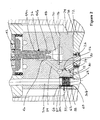
Fig. 2 is a detailed section view of the first embodiment; and -
Fig. 3 is a detailed section view of a second embodiment. -
Figure 1 shows aninjector 10 that embodies one aspect of the present invention. The injector has abody 12 including acentral bore 14 in which aneedle valve 16 reciprocates axially to selectively seal against and lift offseat 18 in the lower portion neartip 20 of the body. A plurality of injection holes ororifices 22 are formed in the tip below thevalve seat 18. Theneedle valve 16 has anupper end 24 situated in aneedle control chamber 26 whereby a combination of hydraulic and spring forces selectively close the nose ofvalve 16 againstseat 18 or lift thevalve 16 from theseat 18, depending on the pressure inchamber 26. - After passing through a high pressure filter (not shown), high pressure fuel is supplied to the injector through
port 28 intomain passage 30, havingupper portion 30a, which leads to thevalve body 12, andlower portion 30b, which is in fluid communication with thebore 14. In a well-known manner, differential area profiles and fluid volumes on and aroundneedle 16 achieve the desired hydraulic balances such that high pressure fuel is selectively discharged throughorifices 22. When theneedle valve 16 is to be closed, high pressure fuel in theneedle control chamber 26 urges theinjector valve 16 against theinjector valve seat 18 to prevent flow of high pressure fuel from thebore 14 to theorifices 22 and when the needle valve is to be opened theneedle control chamber 26 is fluidly connected to low a pressure sump, thereby reducing the fluid pressure in thecontrol chamber 26 and on theupper end 24 of theneedle valve 16, lifting the needle valve off theinjector seat 18 and discharging fuel through theorifices 22. - With reference to
Figures 1 and2 , the invention provides adebris shield 32 within the injector, where some of the high pressure fuel is delivered from the high pressure supply passage (e.g., 30a) via auxiliary passage orbranch 34 to controlvalve 36.Control valve 36 is in fluid communication with and controls the pressure in theneedle control chamber 26, thereby closing and opening theneedle valve 16. Anactuator body 38 is connected to thevalve body 12 by threading to a substantiallytubular body connector 40, and contains asolenoid actuator 42 for apintle 44a or the like that seals against and lifts fromseat 44b.Seat 44b is located such that anupstream region 46 of the control valve chamber is in fluid communication withhigh pressure passage 34 and adownstream region 48 is in fluid communication with a low pressure sump, such as the fuel tank or low pressure fuel delivery line to the high pressure supply pump. - In the illustrated embodiment, the auxiliary flow from high
pressure supply passage 30a enterspassage 50 viapassage 52, the former being in direct fluid communication with theneedle control chamber 26 and withpassage 34. Preferably, theauxiliary passage 52 includes anorifice 54 leading topassage 50, and anotherorifice 56 is situated betweenpassage 50 andpassage 34. - The
debris shield 32 is in the intermediate portion 30c of the high pressurefuel supply passage 30, betweenportions tube 58 with a centralaxial passage 60 and a multiplicity ofradial holes 62 through the tube wall. High pressure fuel for injection passes axially into and out of thetube 58 and high pressure fuel to theupstream side 46 of thecontrol valve 36 passes radially through theholes 62 in the tube. In the illustrated embodiment, the debris shield is in the high pressure fuel supply passage 30c upstream ofbranch passage 52, whereby radial flow through the debris shield enters thepassage 50 andpassage 34. However, inasmuch as the main purpose of the debris shield is to prevent debris from entering thecontrol valve 36, theupstream flow path 34 can be directly fluidly connected to the fluid volume where the radial flow exits the debris shield. - It should thus be appreciated that the
debris shield 32 is in the main high pressurefuel supply passage 30, upstream of thebranch line 34 leading to thecontrol valve 36, and comprises a tube or the like 58 fixed to thebody 12, with acentral passage 60 aligned with the fuel supply passage and a multiplicity oftransverse holes 62 through which high pressure fuel is delivered to thebranch line 34. - The
debris shield 32 is preferably situated in ashield chamber 64 in the body, defined by a shield chamber wall spaced radially from the tube. The tube has opposed ends 66, 68 and the tube is fixed to the body at the ends. Preferably thevalve body 12 comprises anupper portion 70 containing a vertical portion of highpressure supply passage 30a,control valve seat 44b, andupstream entry point 46 ofpassage 34 to theseat 44b. Thevalve body 12 also includes alower portion 72 containing theinjector valve 16,needle control chamber 26, and thelower portion 30b of thefuel supply passage 30. A distinctcentral portion 74 of thevalve body 12 in the form of a plate having upper andlower surfaces lower portions shield chamber 64 fluidly connects the upper andlower portions Auxiliary passage 52,passage 50 to theneedle control chamber 26, andorifices central plate 74. - The nominal distance between opposed ends 66, 68 of the
tube 58 is preferably greater than the distance between theupper surface 76 and thelower surface 78 of thecentral portion 74 of the body, However, in the assembled condition of the injector, thebody portions Fig. 1 ) so thattube 58 is fixed to the body in longitudinal compression between the upper andlower portions - The
shield chamber 64 preferably includes acollection gallery 80 at the intersection with theauxiliary passage 52. All the fuel supplied to thepassage 34 must pass through theholes 62 andgallery 80. Preferably, the gallery extends to thelower surface 78 of thecentral portion 74 of the body, andauxiliary passage 52 extends from the lower surface of the central portion of the body from the gallery at an oblique upward angle toward the axis of thebore 14.Passage 50 terminates within thecentral portion 74 of the body between the first andsecond orifices first portion 30a of the fuel supply passage. - The
holes 62 of the debris shield have a diameter less than 30 microns, preferably about 20 microns. Thecontrol valve pintle 44a is actuated bysolenoid 42 to seal against and lift from aseat 44a with a minimum lift, and the diameter of theholes 62 in the tube should be smaller than this minimum lift. The material composition and wall thickness of thetube 58 should be such that the tube compresses during installation without excessive strain that would affect the diameter of theholes 62. -
Figure 3 shows a second embodiment in which thedebris diverter shield 32 is in a different location within the injector, and the associated passages for achieving control of the injector differ from those shown inFig. 2 InFig. 3 , components which are identical to those shown inFig. 2 carry the same numeric identifier, whereas components that are not identical but provide the same or similar functionality are indicated with a prime ('). In this embodiment, thedebris shield 32 is located in theupper portion 30a' of the high pressure passage within the upper block 70', and thelower portion 30b inblock 72 and intermediate portion 30c' in block 74' are straight bores. - The lower portion of
passage 30a' has a counter bore 82 defining aninternal shoulder 84. Theupper end 66 of thediverter shield 32 bears against theshoulder 84 and thelower end 68 of thediverter shield 32 bears against the upper surface 76' of the intermediate block 74'. As with the embodiment ofFigs. 1 and2 , thediverter shield 32 is thereby compressed and rigidly held in position. - High pressure fuel in
passage 30a' enters thedebris diverter 32, with some flow passing through the transverse holes into gallery 64', branch line 52' and into theneedle control chamber 26. While thecontrol valve 36 is closed, high pressure is maintained in theneedle control chamber 26, passage 50' and passage 34'. Upon lifting of thecontrol valve 36, this pressurized fuel is exposed to the low pressure at 48, thereby inducing the lifting of the needle valve withinchamber 26. - It should be appreciated that a tubular, perforated debris diverter shield can be located anywhere within the injector whereby a main high pressure fuel flow passes axially through the tube and a secondary or auxiliary flow passes transversely through the perforations to a component within the injector that is vulnerable to the presence of small particles of debris. Particularly in the illustrated and analogous embodiments, the pressure drop across the perforations or holes is relatively small. For example, while the
control valve 36 is closed, there is substantially no pressure drop because the passages to the control valve are at the pressure of the fuel insupply line 30. When thecontrol valve 36 opens, the orifices such as at 54 and 56 maintain a relatively high pressure in thegallery 64. Even with pressure in themain passage 30 above 20,000 psi, the pressure drop across the holes can be as low as about 30 psi. One can trade off the lower cost of laser drilling fewer holes against the increase in pressure drop to, e.g., about 100 psi. - The combination of robust main flow axially through the tube, transverse orientation of the perforations, and small pressure drop across the perforations, avoids substantial transverse forces on the particles so they do not even begin extruding through the holes. Due to the low transverse forces on the particles they tend to remain near the entrances to the perforations and are immediately flushed by the main flow to the region of the injector where they can easily pass through the injection orifices.
- It should be appreciated that in a typical implementation for a passenger vehicle, the
debris diverter shield 32 would have a length in the range of about 3-4 mm, an OD of about 2.5 mm, and an ID of about 1.5 mm (e.g., with a wall thickness in the range of about 0.1 to 0.5 mm), and at least about 2000 holes with a diameter in the range of about 20 to 30 microns. However, the dimensions of the diverted shield and the number of holes would be correspondingly larger for heavier end uses, but the size of the holes should remain in the same range for use with the same type of fuel having similar debris characteristics. - The present invention has exhibited a remarkable reduction in the effects of debris contamination in the typical fuel flow to an injector control valve. Raw fuel contains debris having a size up to 1000 microns. Typical filters upstream of the injector permit debris of up to 60 microns effective diameter to pass through to the injector and additional debris may be introduced into the fuel by hardware components in the fuel line downstream of the filters. Typical edge filters at the injector cannot filter debris smaller than 30 - 50 microns and debris of larger size is extruded and thereby reduced in size in the range of 30 - 50 microns before entering the main passage in the injector. Typical fuels have so much debris that even if large particles were diverted within the injector to an accumulation chamber or the like, the capacity would not be large enough to handle the diverted debris accumulated over only a fraction of the desired service life of the injector. The extent of debris reduction according to the invention can vary with particle size distribution in the fuel. However, a comparison of total debris reaching the control valve as between a conventional fuel system with fuel line filter and edge filter at the entrance to the injector, and the same system but with the addition of a debris diverter shield as shown and described herein, showed a reduction by a factor of over 10.
Claims (15)
- A fuel injector (10) having a main high pressure fuel passage (30) and an auxiliary passage (52, 52') from the main passage to an hydraulic component (26, 36) within the injector, characterized by a tubular debris diverter shield (62) in the main passage, whereby a main flow passes axially (60) within an inner wall of the tube and an auxiliary flow passes through a multiplicity of holes (62) extending transversely from the inner wall to an outer wall, before delivery to the hydraulic component.
- The injector of claim 1, characterized by:an elongated body (12) having upper and lower ends, a longitudinal bore (14) leading to an injector valve seat (18) adjacent the lower end and to a tip (20) with discharge holes (22) at the lower end;an injector valve (16) reciprocable in said bore, having a lower end sealable against the injector valve seat and an upper end (24) subject to fluid pressure in an injector control chamber (26);a control valve (36) with an upstream side in fluid communication with said injector control chamber and a downstream side in fluid communication (48) with a low pressure sump;said high pressure fuel supply passage being in fluid communication with said bore upstream of the injector valve seat, with a branch line (52, 52') from the high pressure passage in fluid communication (34, 50, 34', 50') with said injector control chamber and with the upstream side of said control valve;an actuator (42) for selectively closing and opening the control valve, whereby when the control valve is closed high pressure fuel in said control chamber urges the injector valve against the injector valve seat to prevent flow of high pressure fuel from said bore to the discharge holes and when the control valve is opened the control chamber is fluidly connected (48) with the low pressure sump, thereby reducing the fluid pressure in the control chamber and on the upper end of the injector valve, lifting the injector valve off the injector seat and discharging fuel through the discharge holes; andsaid debris shield (32) situated in the high pressure fuel supply passage (30a) upstream of said branch line, with the central passage (60) aligned with the fuel supply passage and with said multiplicity of transverse holes (62) aligned for delivery of high pressure fuel to the branch line.
- The injector of claim 1 or 2, characterized by the debris shield situated in a shield chamber (64, 64') in the body, which shield chamber is defined by a shield chamber wall spaced radially from the tube.
- The injector of any of claims 1-3, characterized in that the tube has opposed ends (66, 68) and the tube is fixed to the body at the ends.
- The injector of any of claims 1-4, characterized in that
the body comprises an upper body portion (70) containing the control valve and an upper portion (30a) of the fuel supply passage, a lower body portion (72) containing the injector valve and a lower portion (30b) of the fuel supply passage, and a distinct central body portion (74) having upper and lower surfaces (76, 78) rigidly trapped between the upper and lower body portions and a shield chamber (64) fluidly connecting the upper and lower portions of the fuel supply passage; and
the debris shield is situated in the shield chamber. - The injector of claim 5, characterized in that the tube has opposed ends (66, 68) extending from the upper to the lower surface of the central body portion, and the tube is fixed to the body in longitudinal compression between the upper and lower body portions.
- The injector of claim 2, characterized in that
said branch line leads from the shield chamber to a first (Z) orifice (54) which delivers fuel to a first passage (50) leading to the injector control chamber;
a second (A) orifice (56) is provided between the first passage and a second passage (34) leading to the control valve; and
the branch line and first and second orifices are in the central body portion. - The injector of claim 7, characterized in that
the holes extend radially through the tube;
the shield chamber is defined by a shield chamber wall spaced radially from the tube and including a collection gallery (80). - The injector of claim 8, characterized in that the branch line extends from the collection gallery into the central body portion.
- The injector of claim 9, characterized in that
the first portion of the fuel supply passage and the tube are coaxially aligned at the upper surface of the central body portion, along a first axis that is parallel to and laterally offset from the bore;
fuel from the first portion of the fuel supply passage must pass through the holes and gallery before flowing to said branch line;
the gallery extends to the lower surface of the central body portion;
the branch line extends from the lower surface of the central body portion from the gallery at an oblique upward angle toward the axis of the bore;
said first passage terminates within the central body portion between the first and second orifices and is oriented along an axis from the injector control chamber obliquely upward toward the first portion of the fuel supply passage. - The injector of any of claims 1-10 characterized in that holes have a diameter less than 50 microns, preferably less than 25 microns.
- The injector of any of claims 1-10, characterized in that the tube has a length in the range of about 3-4 mm, a wall thickness in the range of about 0.1 to 0.5 mm, and the tube has at least about 2000 holes with a diameter in the range of about 20 to 30 microns.
- The injector of claim 1, characterized by:a hydraulically controlled injector valve (16) operatively associated with the fuel supply passage and with injection holes (22) for discharging high pressure fuel from the injector;a control valve (36) hydraulically controlling the injector valve, with an upstream side (46) in fluid communication with said fuel supply passage and a downstream side in fluid communication (48) with a low pressure sump;an actuator (42) for selectively closing and opening the control valve, whereby when the control valve is closed hydraulic forces close the injector valve to prevent flow of high pressure fuel to the discharge holes and when the control valve is opened hydraulic forces open the injector valve to discharge fuel through the discharge holes; andwherein high pressure fuel for injection passes axially through the tube and high pressure fuel to the upstream side of the control valve passes radially through the holes in the tube.
- The injector of claim 13, characterized in that
the tube is situated in a shield chamber (64) having a gallery (80) outside the tube for accumulating fuel that has passed through the holes;
all the high pressure fuel for injection passes axially through the tube and all the high pressure fuel to the upstream side of the control valve passes from the gallery through at least one orifice (54, 56). - The injector of claim 14, characterized in that the control valve has a pintle (44) that is actuated by a solenoid to seal against and lift from a seat (46) with a minimum lift and the diameter of the holes in the tube is smaller than said minimum lift.
Applications Claiming Priority (1)
| Application Number | Priority Date | Filing Date | Title |
|---|---|---|---|
| US14/084,840 US9644589B2 (en) | 2013-11-20 | 2013-11-20 | Debris diverter shield for fuel injector |
Publications (2)
| Publication Number | Publication Date |
|---|---|
| EP2876295A1 true EP2876295A1 (en) | 2015-05-27 |
| EP2876295B1 EP2876295B1 (en) | 2019-03-06 |
Family
ID=51494157
Family Applications (1)
| Application Number | Title | Priority Date | Filing Date |
|---|---|---|---|
| EP14184067.8A Not-in-force EP2876295B1 (en) | 2013-11-20 | 2014-09-09 | Fuel injector with a debris diverter shield |
Country Status (4)
| Country | Link |
|---|---|
| US (1) | US9644589B2 (en) |
| EP (1) | EP2876295B1 (en) |
| CN (1) | CN104675594B (en) |
| IN (1) | IN2014MU02519A (en) |
Cited By (1)
| Publication number | Priority date | Publication date | Assignee | Title |
|---|---|---|---|---|
| WO2017194625A1 (en) * | 2016-05-13 | 2017-11-16 | Delphi International Operations Luxembourg S.À R.L. | Fuel injector for an internal combustion engine |
Families Citing this family (6)
| Publication number | Priority date | Publication date | Assignee | Title |
|---|---|---|---|---|
| US20170234284A1 (en) * | 2013-11-20 | 2017-08-17 | Stanadyne Llc | Woven Mesh Debris Shield for Fuel Injector |
| EP2940286A1 (en) * | 2014-05-01 | 2015-11-04 | Delphi International Operations Luxembourg S.à r.l. | Fuel injector filter |
| GB2564654A (en) * | 2017-07-17 | 2019-01-23 | Delphi Int Operations Luxembourg Sarl | High pressure fuel pump |
| US10830196B2 (en) * | 2018-11-29 | 2020-11-10 | Caterpillar Inc. | Filter for fuel injectors |
| US11098685B2 (en) | 2019-02-19 | 2021-08-24 | Caterpillar Inc. | Fuel injector assembly having external filter and method of making same |
| US12006902B2 (en) * | 2021-03-03 | 2024-06-11 | Caterpillar Inc. | Fuel injector and fuel system having integral filter supported in valve seat plate, and valve seat plate and filter assembly |
Citations (4)
| Publication number | Priority date | Publication date | Assignee | Title |
|---|---|---|---|---|
| WO2007012433A1 (en) * | 2005-07-28 | 2007-02-01 | L'orange Gmbh | Fuel injector |
| DE102005062547A1 (en) * | 2005-12-27 | 2007-07-05 | Robert Bosch Gmbh | Fuel injecting device e.g. pump nozzle system, for internal combustion engine, has housing and fuel channels in housing, where filter unit is available for filtering fuel and other filter unit is assigned to fuel channel |
| DE102007049963A1 (en) * | 2007-10-18 | 2009-04-23 | Robert Bosch Gmbh | Fuel injector |
| DE102011053113A1 (en) * | 2011-08-30 | 2013-02-28 | L'orange Gmbh | Filter arrangement for fuel injector, has filter lying at branches of secondary channel, and body formed by filter case freely flow throughable in extending direction of primary channel, where filter case is clamped in primary channel |
Family Cites Families (23)
| Publication number | Priority date | Publication date | Assignee | Title |
|---|---|---|---|---|
| US4649950A (en) * | 1985-11-27 | 1987-03-17 | Ex-Cell-O Corporation | Fuel nozzle assembly with integral valve assembly and inlet wash filter and primary fuel take-off |
| GB9508623D0 (en) * | 1995-04-28 | 1995-06-14 | Lucas Ind Plc | "Fuel injection nozzle" |
| IT1319838B1 (en) * | 2000-02-15 | 2003-11-03 | Elasis Sistema Ricerca Fiat | IMPROVEMENT OF A SOLENOID VALVE FOR THE ADJUSTMENT OF THE PRESSURE OF FUEL SUPPLY TO A COMBUSTION ENGINE |
| DE10025497A1 (en) * | 2000-05-23 | 2001-11-29 | Bosch Gmbh Robert | Fuel injector |
| DE10051549A1 (en) * | 2000-10-18 | 2002-04-25 | Bosch Gmbh Robert | Solenoid valve to control fuel injection valve of IC engines has armature pin with part sliding between fixed and moveable stop |
| DE10052604A1 (en) * | 2000-10-24 | 2002-05-02 | Bosch Gmbh Robert | Solenoid valve for control of injection valve of IC engine with solenoid and movable armature and control valve element working together with valve seat for opening/closing fuel |
| JP4138481B2 (en) * | 2000-11-23 | 2008-08-27 | ローベルト ボツシユ ゲゼルシヤフト ミツト ベシユレンクテル ハフツング | Magnet valve for control of injection valve of internal combustion engine |
| DE10063193A1 (en) * | 2000-12-19 | 2002-06-27 | Bosch Gmbh Robert | Solenoid valve for controlling an injection valve of an internal combustion engine |
| DE10100422A1 (en) * | 2001-01-08 | 2002-07-11 | Bosch Gmbh Robert | Solenoid valve for controlling an injection valve of an internal combustion engine |
| DE10220632A1 (en) * | 2001-05-10 | 2002-12-12 | Denso Corp | Filter in fuel injection device has body with cylindrical sector perforated by holes arranged in spiral round cylindrical sector |
| DE10208569A1 (en) * | 2002-02-27 | 2003-09-25 | Hatz Motoren | Injector with fuel filter |
| JP3841054B2 (en) * | 2002-08-08 | 2006-11-01 | 株式会社デンソー | Filter and fuel injection device using the same |
| TR200402049A1 (en) * | 2004-08-18 | 2006-03-21 | Robert Bosch Gmbh | Injector with integrated filter. |
| DE102004049288A1 (en) * | 2004-10-09 | 2006-04-20 | Robert Bosch Gmbh | Fuel injector with molded valve seat to reduce the anchor stroke |
| DE102007029793A1 (en) * | 2007-06-27 | 2008-07-17 | L'orange Gmbh | Fuel injector for internal combustion engines, has high pressure area extending in axial direction and allows injecting fuel staying below high pressure |
| JP5064341B2 (en) * | 2007-11-02 | 2012-10-31 | 株式会社デンソー | Fuel injection valve and fuel injection device |
| JP5079643B2 (en) * | 2007-11-02 | 2012-11-21 | 株式会社デンソー | Fuel injection valve and fuel injection device |
| JP5079650B2 (en) * | 2007-11-02 | 2012-11-21 | 株式会社デンソー | Fuel injection valve and fuel injection device |
| FR2928207B1 (en) * | 2008-02-29 | 2010-03-26 | Hispano Suiza Sa | THERMAL EXCHANGER INSTALLATION |
| DE102008041730A1 (en) * | 2008-09-01 | 2010-03-04 | Robert Bosch Gmbh | Injector with a particle filter arranged in front of the inlet throttle |
| EP2466116B1 (en) * | 2010-12-15 | 2014-07-30 | KW Technologie GmbH & Co. KG | Pulsation dampener |
| DE102012201940A1 (en) * | 2012-02-09 | 2013-08-14 | Robert Bosch Gmbh | Valve for metering a flowing medium |
| US20150008271A1 (en) * | 2013-07-02 | 2015-01-08 | Caterpillar Inc. | Injector Orifice Plate Filter |
-
2013
- 2013-11-20 US US14/084,840 patent/US9644589B2/en active Active
-
2014
- 2014-08-05 IN IN2519MU2014 patent/IN2014MU02519A/en unknown
- 2014-09-09 EP EP14184067.8A patent/EP2876295B1/en not_active Not-in-force
- 2014-11-14 CN CN201410649410.9A patent/CN104675594B/en not_active Expired - Fee Related
Patent Citations (4)
| Publication number | Priority date | Publication date | Assignee | Title |
|---|---|---|---|---|
| WO2007012433A1 (en) * | 2005-07-28 | 2007-02-01 | L'orange Gmbh | Fuel injector |
| DE102005062547A1 (en) * | 2005-12-27 | 2007-07-05 | Robert Bosch Gmbh | Fuel injecting device e.g. pump nozzle system, for internal combustion engine, has housing and fuel channels in housing, where filter unit is available for filtering fuel and other filter unit is assigned to fuel channel |
| DE102007049963A1 (en) * | 2007-10-18 | 2009-04-23 | Robert Bosch Gmbh | Fuel injector |
| DE102011053113A1 (en) * | 2011-08-30 | 2013-02-28 | L'orange Gmbh | Filter arrangement for fuel injector, has filter lying at branches of secondary channel, and body formed by filter case freely flow throughable in extending direction of primary channel, where filter case is clamped in primary channel |
Cited By (2)
| Publication number | Priority date | Publication date | Assignee | Title |
|---|---|---|---|---|
| WO2017194625A1 (en) * | 2016-05-13 | 2017-11-16 | Delphi International Operations Luxembourg S.À R.L. | Fuel injector for an internal combustion engine |
| FR3051229A1 (en) * | 2016-05-13 | 2017-11-17 | Delphi Int Operations Luxembourg Sarl | FUEL INJECTOR FOR INTERNAL COMBUSTION ENGINE |
Also Published As
| Publication number | Publication date |
|---|---|
| US20150136088A1 (en) | 2015-05-21 |
| EP2876295B1 (en) | 2019-03-06 |
| IN2014MU02519A (en) | 2015-10-09 |
| CN104675594A (en) | 2015-06-03 |
| CN104675594B (en) | 2018-06-26 |
| US9644589B2 (en) | 2017-05-09 |
Similar Documents
| Publication | Publication Date | Title |
|---|---|---|
| EP2876295B1 (en) | Fuel injector with a debris diverter shield | |
| CN107002603A (en) | Low-pressure regulating system of a fuel delivery device of a fuel injection system and a discharge valve therefor | |
| EP2940287A1 (en) | Fuel injector filter | |
| WO2009121662A1 (en) | Fuel injection system for an internal combustion engine | |
| EP2387661B1 (en) | Fuel injector for internal combustion engines | |
| DE102005035347B3 (en) | Fuel injector for an internal combustion engine has an axial hole for fuel in a nozzle/jet unit with an injector needle sliding on-axis in the nozzle/jet unit | |
| DE112008003703T5 (en) | Fuel injection system | |
| US20170051714A1 (en) | Fuel Injector Filter | |
| DE102009055267A1 (en) | Pressure compensated fuel injector with bypass and minimized valve volume | |
| US20170234284A1 (en) | Woven Mesh Debris Shield for Fuel Injector | |
| DE102011083005B4 (en) | Method for flushing an armature chamber of a solenoid valve intended for controlling a fluid mass flow and solenoid valve | |
| EP1910663B1 (en) | Fuel injection device for an internal combustion engine using direct fuel injection | |
| WO2012075483A2 (en) | Check valve for high-pressure fuel injector | |
| DE19860468A1 (en) | Fuel injection system | |
| DE10036868B4 (en) | Injector for an injection system comprising a high-pressure plenum | |
| US6793159B2 (en) | Fuel injector | |
| DE19839579C1 (en) | Two=stage filtering system for fuel supply to injectors | |
| DE102007016625A1 (en) | Valve and injection system for an internal combustion engine with valve | |
| CN101956636A (en) | The parallel line fuel filter that is used for fuel injector | |
| CN215170489U (en) | Oil nozzle of single-cylinder air-cooled diesel engine | |
| DE102014001139B4 (en) | fuel injector | |
| US9303604B2 (en) | Asymmetrical orifice for bypass control | |
| DE102012213535A1 (en) | Fuel injector has outer contour whose diameter on case inner surface is smaller than diameter of outer contour on case outer surface | |
| DE102016101425A1 (en) | Quantity limiting valve, in particular for a high-pressure pump system | |
| DE102010002797A1 (en) | Suction valve of a fuel supply system of an internal combustion engine |
Legal Events
| Date | Code | Title | Description |
|---|---|---|---|
| PUAI | Public reference made under article 153(3) epc to a published international application that has entered the european phase |
Free format text: ORIGINAL CODE: 0009012 |
|
| 17P | Request for examination filed |
Effective date: 20140909 |
|
| AK | Designated contracting states |
Kind code of ref document: A1 Designated state(s): AL AT BE BG CH CY CZ DE DK EE ES FI FR GB GR HR HU IE IS IT LI LT LU LV MC MK MT NL NO PL PT RO RS SE SI SK SM TR |
|
| AX | Request for extension of the european patent |
Extension state: BA ME |
|
| R17P | Request for examination filed (corrected) |
Effective date: 20151126 |
|
| RBV | Designated contracting states (corrected) |
Designated state(s): AL AT BE BG CH CY CZ DE DK EE ES FI FR GB GR HR HU IE IS IT LI LT LU LV MC MK MT NL NO PL PT RO RS SE SI SK SM TR |
|
| STAA | Information on the status of an ep patent application or granted ep patent |
Free format text: STATUS: EXAMINATION IS IN PROGRESS |
|
| 17Q | First examination report despatched |
Effective date: 20170421 |
|
| GRAP | Despatch of communication of intention to grant a patent |
Free format text: ORIGINAL CODE: EPIDOSNIGR1 |
|
| STAA | Information on the status of an ep patent application or granted ep patent |
Free format text: STATUS: GRANT OF PATENT IS INTENDED |
|
| INTG | Intention to grant announced |
Effective date: 20181016 |
|
| GRAS | Grant fee paid |
Free format text: ORIGINAL CODE: EPIDOSNIGR3 |
|
| GRAA | (expected) grant |
Free format text: ORIGINAL CODE: 0009210 |
|
| STAA | Information on the status of an ep patent application or granted ep patent |
Free format text: STATUS: THE PATENT HAS BEEN GRANTED |
|
| AK | Designated contracting states |
Kind code of ref document: B1 Designated state(s): AL AT BE BG CH CY CZ DE DK EE ES FI FR GB GR HR HU IE IS IT LI LT LU LV MC MK MT NL NO PL PT RO RS SE SI SK SM TR |
|
| REG | Reference to a national code |
Ref country code: GB Ref legal event code: FG4D |
|
| REG | Reference to a national code |
Ref country code: CH Ref legal event code: EP Ref country code: AT Ref legal event code: REF Ref document number: 1104878 Country of ref document: AT Kind code of ref document: T Effective date: 20190315 |
|
| REG | Reference to a national code |
Ref country code: DE Ref legal event code: R096 Ref document number: 602014042220 Country of ref document: DE |
|
| REG | Reference to a national code |
Ref country code: IE Ref legal event code: FG4D |
|
| RAP2 | Party data changed (patent owner data changed or rights of a patent transferred) |
Owner name: STANADYNE LLC |
|
| REG | Reference to a national code |
Ref country code: DE Ref legal event code: R082 Ref document number: 602014042220 Country of ref document: DE Representative=s name: GLAWE DELFS MOLL PARTNERSCHAFT MBB VON PATENT-, DE Ref country code: DE Ref legal event code: R081 Ref document number: 602014042220 Country of ref document: DE Owner name: STANADYNE LLC, WINDSOR, US Free format text: FORMER OWNER: STANADYNE CORP., WINDSOR, CONN., US |
|
| REG | Reference to a national code |
Ref country code: NL Ref legal event code: MP Effective date: 20190306 |
|
| REG | Reference to a national code |
Ref country code: LT Ref legal event code: MG4D |
|
| PG25 | Lapsed in a contracting state [announced via postgrant information from national office to epo] |
Ref country code: SE Free format text: LAPSE BECAUSE OF FAILURE TO SUBMIT A TRANSLATION OF THE DESCRIPTION OR TO PAY THE FEE WITHIN THE PRESCRIBED TIME-LIMIT Effective date: 20190306 Ref country code: FI Free format text: LAPSE BECAUSE OF FAILURE TO SUBMIT A TRANSLATION OF THE DESCRIPTION OR TO PAY THE FEE WITHIN THE PRESCRIBED TIME-LIMIT Effective date: 20190306 Ref country code: NO Free format text: LAPSE BECAUSE OF FAILURE TO SUBMIT A TRANSLATION OF THE DESCRIPTION OR TO PAY THE FEE WITHIN THE PRESCRIBED TIME-LIMIT Effective date: 20190606 Ref country code: LT Free format text: LAPSE BECAUSE OF FAILURE TO SUBMIT A TRANSLATION OF THE DESCRIPTION OR TO PAY THE FEE WITHIN THE PRESCRIBED TIME-LIMIT Effective date: 20190306 |
|
| PG25 | Lapsed in a contracting state [announced via postgrant information from national office to epo] |
Ref country code: BG Free format text: LAPSE BECAUSE OF FAILURE TO SUBMIT A TRANSLATION OF THE DESCRIPTION OR TO PAY THE FEE WITHIN THE PRESCRIBED TIME-LIMIT Effective date: 20190606 Ref country code: GR Free format text: LAPSE BECAUSE OF FAILURE TO SUBMIT A TRANSLATION OF THE DESCRIPTION OR TO PAY THE FEE WITHIN THE PRESCRIBED TIME-LIMIT Effective date: 20190607 Ref country code: HR Free format text: LAPSE BECAUSE OF FAILURE TO SUBMIT A TRANSLATION OF THE DESCRIPTION OR TO PAY THE FEE WITHIN THE PRESCRIBED TIME-LIMIT Effective date: 20190306 Ref country code: LV Free format text: LAPSE BECAUSE OF FAILURE TO SUBMIT A TRANSLATION OF THE DESCRIPTION OR TO PAY THE FEE WITHIN THE PRESCRIBED TIME-LIMIT Effective date: 20190306 Ref country code: NL Free format text: LAPSE BECAUSE OF FAILURE TO SUBMIT A TRANSLATION OF THE DESCRIPTION OR TO PAY THE FEE WITHIN THE PRESCRIBED TIME-LIMIT Effective date: 20190306 Ref country code: RS Free format text: LAPSE BECAUSE OF FAILURE TO SUBMIT A TRANSLATION OF THE DESCRIPTION OR TO PAY THE FEE WITHIN THE PRESCRIBED TIME-LIMIT Effective date: 20190306 |
|
| REG | Reference to a national code |
Ref country code: AT Ref legal event code: MK05 Ref document number: 1104878 Country of ref document: AT Kind code of ref document: T Effective date: 20190306 |
|
| PG25 | Lapsed in a contracting state [announced via postgrant information from national office to epo] |
Ref country code: CZ Free format text: LAPSE BECAUSE OF FAILURE TO SUBMIT A TRANSLATION OF THE DESCRIPTION OR TO PAY THE FEE WITHIN THE PRESCRIBED TIME-LIMIT Effective date: 20190306 Ref country code: IT Free format text: LAPSE BECAUSE OF FAILURE TO SUBMIT A TRANSLATION OF THE DESCRIPTION OR TO PAY THE FEE WITHIN THE PRESCRIBED TIME-LIMIT Effective date: 20190306 Ref country code: ES Free format text: LAPSE BECAUSE OF FAILURE TO SUBMIT A TRANSLATION OF THE DESCRIPTION OR TO PAY THE FEE WITHIN THE PRESCRIBED TIME-LIMIT Effective date: 20190306 Ref country code: RO Free format text: LAPSE BECAUSE OF FAILURE TO SUBMIT A TRANSLATION OF THE DESCRIPTION OR TO PAY THE FEE WITHIN THE PRESCRIBED TIME-LIMIT Effective date: 20190306 Ref country code: EE Free format text: LAPSE BECAUSE OF FAILURE TO SUBMIT A TRANSLATION OF THE DESCRIPTION OR TO PAY THE FEE WITHIN THE PRESCRIBED TIME-LIMIT Effective date: 20190306 Ref country code: AL Free format text: LAPSE BECAUSE OF FAILURE TO SUBMIT A TRANSLATION OF THE DESCRIPTION OR TO PAY THE FEE WITHIN THE PRESCRIBED TIME-LIMIT Effective date: 20190306 Ref country code: SK Free format text: LAPSE BECAUSE OF FAILURE TO SUBMIT A TRANSLATION OF THE DESCRIPTION OR TO PAY THE FEE WITHIN THE PRESCRIBED TIME-LIMIT Effective date: 20190306 Ref country code: PT Free format text: LAPSE BECAUSE OF FAILURE TO SUBMIT A TRANSLATION OF THE DESCRIPTION OR TO PAY THE FEE WITHIN THE PRESCRIBED TIME-LIMIT Effective date: 20190706 |
|
| PG25 | Lapsed in a contracting state [announced via postgrant information from national office to epo] |
Ref country code: PL Free format text: LAPSE BECAUSE OF FAILURE TO SUBMIT A TRANSLATION OF THE DESCRIPTION OR TO PAY THE FEE WITHIN THE PRESCRIBED TIME-LIMIT Effective date: 20190306 Ref country code: SM Free format text: LAPSE BECAUSE OF FAILURE TO SUBMIT A TRANSLATION OF THE DESCRIPTION OR TO PAY THE FEE WITHIN THE PRESCRIBED TIME-LIMIT Effective date: 20190306 |
|
| REG | Reference to a national code |
Ref country code: DE Ref legal event code: R097 Ref document number: 602014042220 Country of ref document: DE |
|
| PG25 | Lapsed in a contracting state [announced via postgrant information from national office to epo] |
Ref country code: AT Free format text: LAPSE BECAUSE OF FAILURE TO SUBMIT A TRANSLATION OF THE DESCRIPTION OR TO PAY THE FEE WITHIN THE PRESCRIBED TIME-LIMIT Effective date: 20190306 Ref country code: IS Free format text: LAPSE BECAUSE OF FAILURE TO SUBMIT A TRANSLATION OF THE DESCRIPTION OR TO PAY THE FEE WITHIN THE PRESCRIBED TIME-LIMIT Effective date: 20190706 |
|
| PLBE | No opposition filed within time limit |
Free format text: ORIGINAL CODE: 0009261 |
|
| STAA | Information on the status of an ep patent application or granted ep patent |
Free format text: STATUS: NO OPPOSITION FILED WITHIN TIME LIMIT |
|
| PG25 | Lapsed in a contracting state [announced via postgrant information from national office to epo] |
Ref country code: DK Free format text: LAPSE BECAUSE OF FAILURE TO SUBMIT A TRANSLATION OF THE DESCRIPTION OR TO PAY THE FEE WITHIN THE PRESCRIBED TIME-LIMIT Effective date: 20190306 |
|
| 26N | No opposition filed |
Effective date: 20191209 |
|
| PG25 | Lapsed in a contracting state [announced via postgrant information from national office to epo] |
Ref country code: SI Free format text: LAPSE BECAUSE OF FAILURE TO SUBMIT A TRANSLATION OF THE DESCRIPTION OR TO PAY THE FEE WITHIN THE PRESCRIBED TIME-LIMIT Effective date: 20190306 |
|
| PG25 | Lapsed in a contracting state [announced via postgrant information from national office to epo] |
Ref country code: TR Free format text: LAPSE BECAUSE OF FAILURE TO SUBMIT A TRANSLATION OF THE DESCRIPTION OR TO PAY THE FEE WITHIN THE PRESCRIBED TIME-LIMIT Effective date: 20190306 |
|
| PG25 | Lapsed in a contracting state [announced via postgrant information from national office to epo] |
Ref country code: MC Free format text: LAPSE BECAUSE OF FAILURE TO SUBMIT A TRANSLATION OF THE DESCRIPTION OR TO PAY THE FEE WITHIN THE PRESCRIBED TIME-LIMIT Effective date: 20190306 |
|
| REG | Reference to a national code |
Ref country code: CH Ref legal event code: PL |
|
| PG25 | Lapsed in a contracting state [announced via postgrant information from national office to epo] |
Ref country code: IE Free format text: LAPSE BECAUSE OF NON-PAYMENT OF DUE FEES Effective date: 20190909 Ref country code: LU Free format text: LAPSE BECAUSE OF NON-PAYMENT OF DUE FEES Effective date: 20190909 Ref country code: CH Free format text: LAPSE BECAUSE OF NON-PAYMENT OF DUE FEES Effective date: 20190930 Ref country code: LI Free format text: LAPSE BECAUSE OF NON-PAYMENT OF DUE FEES Effective date: 20190930 |
|
| REG | Reference to a national code |
Ref country code: BE Ref legal event code: MM Effective date: 20190930 |
|
| PG25 | Lapsed in a contracting state [announced via postgrant information from national office to epo] |
Ref country code: BE Free format text: LAPSE BECAUSE OF NON-PAYMENT OF DUE FEES Effective date: 20190930 |
|
| PG25 | Lapsed in a contracting state [announced via postgrant information from national office to epo] |
Ref country code: CY Free format text: LAPSE BECAUSE OF FAILURE TO SUBMIT A TRANSLATION OF THE DESCRIPTION OR TO PAY THE FEE WITHIN THE PRESCRIBED TIME-LIMIT Effective date: 20190306 |
|
| PG25 | Lapsed in a contracting state [announced via postgrant information from national office to epo] |
Ref country code: HU Free format text: LAPSE BECAUSE OF FAILURE TO SUBMIT A TRANSLATION OF THE DESCRIPTION OR TO PAY THE FEE WITHIN THE PRESCRIBED TIME-LIMIT; INVALID AB INITIO Effective date: 20140909 Ref country code: MT Free format text: LAPSE BECAUSE OF FAILURE TO SUBMIT A TRANSLATION OF THE DESCRIPTION OR TO PAY THE FEE WITHIN THE PRESCRIBED TIME-LIMIT Effective date: 20190306 |
|
| PGFP | Annual fee paid to national office [announced via postgrant information from national office to epo] |
Ref country code: FR Payment date: 20210927 Year of fee payment: 8 |
|
| PGFP | Annual fee paid to national office [announced via postgrant information from national office to epo] |
Ref country code: GB Payment date: 20210927 Year of fee payment: 8 Ref country code: DE Payment date: 20210929 Year of fee payment: 8 |
|
| PG25 | Lapsed in a contracting state [announced via postgrant information from national office to epo] |
Ref country code: MK Free format text: LAPSE BECAUSE OF FAILURE TO SUBMIT A TRANSLATION OF THE DESCRIPTION OR TO PAY THE FEE WITHIN THE PRESCRIBED TIME-LIMIT Effective date: 20190306 |
|
| REG | Reference to a national code |
Ref country code: DE Ref legal event code: R119 Ref document number: 602014042220 Country of ref document: DE |
|
| GBPC | Gb: european patent ceased through non-payment of renewal fee |
Effective date: 20220909 |
|
| PG25 | Lapsed in a contracting state [announced via postgrant information from national office to epo] |
Ref country code: FR Free format text: LAPSE BECAUSE OF NON-PAYMENT OF DUE FEES Effective date: 20220930 Ref country code: DE Free format text: LAPSE BECAUSE OF NON-PAYMENT OF DUE FEES Effective date: 20230401 |
|
| PG25 | Lapsed in a contracting state [announced via postgrant information from national office to epo] |
Ref country code: GB Free format text: LAPSE BECAUSE OF NON-PAYMENT OF DUE FEES Effective date: 20220909 |