EP2876288A1 - Aircraft propulsion system fan case comprising thrust reversing assembly - Google Patents
Aircraft propulsion system fan case comprising thrust reversing assembly Download PDFInfo
- Publication number
- EP2876288A1 EP2876288A1 EP14194342.3A EP14194342A EP2876288A1 EP 2876288 A1 EP2876288 A1 EP 2876288A1 EP 14194342 A EP14194342 A EP 14194342A EP 2876288 A1 EP2876288 A1 EP 2876288A1
- Authority
- EP
- European Patent Office
- Prior art keywords
- propulsion system
- blocker door
- aircraft propulsion
- fan case
- cascade array
- Prior art date
- Legal status (The legal status is an assumption and is not a legal conclusion. Google has not performed a legal analysis and makes no representation as to the accuracy of the status listed.)
- Granted
Links
- 230000007246 mechanism Effects 0.000 claims description 4
- 230000004044 response Effects 0.000 claims description 3
- 238000000034 method Methods 0.000 description 9
- 230000008901 benefit Effects 0.000 description 4
- 230000008569 process Effects 0.000 description 3
- 239000000446 fuel Substances 0.000 description 2
- 238000010348 incorporation Methods 0.000 description 2
- 238000000926 separation method Methods 0.000 description 2
- 241000270728 Alligator Species 0.000 description 1
- 239000004215 Carbon black (E152) Substances 0.000 description 1
- 230000006978 adaptation Effects 0.000 description 1
- QVGXLLKOCUKJST-UHFFFAOYSA-N atomic oxygen Chemical compound [O] QVGXLLKOCUKJST-UHFFFAOYSA-N 0.000 description 1
- 230000004323 axial length Effects 0.000 description 1
- 230000000903 blocking effect Effects 0.000 description 1
- 238000010276 construction Methods 0.000 description 1
- 230000008878 coupling Effects 0.000 description 1
- 238000010168 coupling process Methods 0.000 description 1
- 238000005859 coupling reaction Methods 0.000 description 1
- 230000008030 elimination Effects 0.000 description 1
- 238000003379 elimination reaction Methods 0.000 description 1
- 229930195733 hydrocarbon Natural products 0.000 description 1
- 150000002430 hydrocarbons Chemical class 0.000 description 1
- 229910052760 oxygen Inorganic materials 0.000 description 1
- 239000001301 oxygen Substances 0.000 description 1
- 238000004904 shortening Methods 0.000 description 1
Images


Classifications
-
- F—MECHANICAL ENGINEERING; LIGHTING; HEATING; WEAPONS; BLASTING
- F02—COMBUSTION ENGINES; HOT-GAS OR COMBUSTION-PRODUCT ENGINE PLANTS
- F02K—JET-PROPULSION PLANTS
- F02K1/00—Plants characterised by the form or arrangement of the jet pipe or nozzle; Jet pipes or nozzles peculiar thereto
- F02K1/54—Nozzles having means for reversing jet thrust
- F02K1/64—Reversing fan flow
- F02K1/70—Reversing fan flow using thrust reverser flaps or doors mounted on the fan housing
- F02K1/72—Reversing fan flow using thrust reverser flaps or doors mounted on the fan housing the aft end of the fan housing being movable to uncover openings in the fan housing for the reversed flow
-
- F—MECHANICAL ENGINEERING; LIGHTING; HEATING; WEAPONS; BLASTING
- F02—COMBUSTION ENGINES; HOT-GAS OR COMBUSTION-PRODUCT ENGINE PLANTS
- F02K—JET-PROPULSION PLANTS
- F02K1/00—Plants characterised by the form or arrangement of the jet pipe or nozzle; Jet pipes or nozzles peculiar thereto
- F02K1/54—Nozzles having means for reversing jet thrust
- F02K1/76—Control or regulation of thrust reversers
- F02K1/763—Control or regulation of thrust reversers with actuating systems or actuating devices; Arrangement of actuators for thrust reversers
-
- F—MECHANICAL ENGINEERING; LIGHTING; HEATING; WEAPONS; BLASTING
- F02—COMBUSTION ENGINES; HOT-GAS OR COMBUSTION-PRODUCT ENGINE PLANTS
- F02K—JET-PROPULSION PLANTS
- F02K1/00—Plants characterised by the form or arrangement of the jet pipe or nozzle; Jet pipes or nozzles peculiar thereto
- F02K1/54—Nozzles having means for reversing jet thrust
- F02K1/76—Control or regulation of thrust reversers
- F02K1/766—Control or regulation of thrust reversers with blocking systems or locking devices; Arrangement of locking devices for thrust reversers
-
- F—MECHANICAL ENGINEERING; LIGHTING; HEATING; WEAPONS; BLASTING
- F05—INDEXING SCHEMES RELATING TO ENGINES OR PUMPS IN VARIOUS SUBCLASSES OF CLASSES F01-F04
- F05D—INDEXING SCHEME FOR ASPECTS RELATING TO NON-POSITIVE-DISPLACEMENT MACHINES OR ENGINES, GAS-TURBINES OR JET-PROPULSION PLANTS
- F05D2250/00—Geometry
- F05D2250/40—Movement of components
- F05D2250/41—Movement of components with one degree of freedom
- F05D2250/411—Movement of components with one degree of freedom in rotation
Definitions
- the present disclosure relates to a nacelle system for a jet aircraft propulsion system, and more particularly, to a thrust reversing assembly of a nacelle system.
- Jet aircraft propulsion systems typically include a structure known as a nacelle.
- the nacelle may include a variety of components, including an inner fixed structure ("IFS") situated substantially concentrically about an engine core.
- An aerodynamic structure known as an outer barrel (which may be divided into a variety of sections) may be situated substantially coaxially with and concentrically about the IFS.
- the radial separation between the inner surface of the outer barrel and the outer surface of the IFS may define a bypass air duct through which bypass air may flow. Further, air may flow over an outer barrel during flight. This airflow may be defined as a "slip stream.”
- the nacelle may comprise a thrust reversing assembly.
- the thrust reversing assembly may comprise a vented structure known generally as a cascade array.
- a translating sleeve comprising a portion of the outer barrel may translate or shift aft to expose the cascade array to create a passage from the bypass duct through the outer barrel.
- a plurality of structures typically referred to as blocker doors may deploy within the bypass air duct to turn airflow in the bypass air duct through the cascade array.
- the thrust reversing assembly may generate reverse thrust.
- An aircraft propulsion system comprising a generally annular fan case defined by a fan configured to be disposed at a forward end thereof and a stator blade array configured to be disposed at an aft end thereof, a thrust reversing assembly comprising at least a portion of the fan case, the fan case comprising a generally annular cascade array, and/or a sleeve situated at least partially about the cascade array, the sleeve configured to deploy to expose the cascade array.
- the aircraft propulsion system may further comprise a blocker door coupled to at least one of the cascade array and an inner surface of the fan case, the blocker door configured to deploy to redirect airflow through the cascade array.
- the aircraft propulsion system may further comprise a blocker door configured to cover an inner surface of the cascade array such that bypass air flows through a bypass air duct defined between the blocker door and an inner fixed structure disposed radially inward of the blocker door.
- the aircraft propulsion system may further comprise a substantially annular outer barrel, the outer barrel comprising a fan cowl situated concentrically about the fan case, the sleeve comprising a portion of the fan cowl.
- the sleeve may translate axially in an aft direction to expose the cascade array.
- the sleeve may hinge radially outward from the cascade array to expose the cascade array.
- the aircraft propulsion system may further comprise a blocker door that is angled into the direction of airflow within a bypass air duct, and wherein an actuating mechanism coupled to the blocker door is capable of stowing the blocker door in response to an aborted landing.
- tail refers to the direction associated with the tail (e.g., the back end) of an aircraft, or generally, to the direction of exhaust of the engine.
- forward refers to the direction associated with the nose (e.g., the front end) of an aircraft, or generally, to the direction of flight.
- the nacelle may extend along the axis defined by the line marked A-A'.
- the portion near A may be referred to as forward and the portion near A' may be referred to as aft.
- A is forward of A' and A' is aft of A.
- the propulsion system 100 may generally comprise an outer barrel 102, an IFS 104, and a supporting structure or pylon 106.
- the outer barrel 102 may comprise a generally annular structure defined by an outer surface situated radially outward of an inner surface.
- the IFS 104 may comprise a generally annular structure defined by an outer surface situated radially outward of an inner surface thereof.
- the IFS 104 may surround an engine core, which may burn a hydrocarbon fuel in the presence of oxygen to generate thrust.
- the inner surface of the outer barrel 102 may be situated substantially coaxially with and concentrically about the outer surface of the IFS 104.
- the radial separation between the inner surface of the outer barrel 102 and the outer surface of the IFS 104 may define a bypass air duct 108 through which bypass air may flow as a fan 110 rotates to drive air into the bypass air duct 108.
- the outer barrel 102 may be divided into a plurality of sections.
- the outer barrel 102 may comprise a fan cowl 112 and a thrust reversing assembly 101.
- the thrust reversing assembly may be situated aft of the fan cowl 112, and may include a translating sleeve 114, also situated aft of the fan cowl 112.
- the thrust reversing assembly 101 may also comprise a variety of components including, for example, a cascade array 116, and a plurality of bypass air blocking structures or blocker doors 118.
- the thrust reversing assembly 101, including the translating sleeve 114, cascade array 116, and blocker doors 118 (shown stowed) may be situated aft of the fan cowl 112.
- the fan cowl 112 may be coupled to a generally annular fan case 120 situated inward of the fan cowl 112.
- the fan case 120 may extend axially, from forward to aft, substantially between the fan 110 and a stator blade array 115).
- the translating sleeve 114 may translate or shift aft to expose the cascade array 116, and the plurality of blocker doors 118 may deploy within the bypass air duct 108 to turn airflow into and through the cascade array 116 to produce reverse thrust.
- the translating sleeve 114 (and more generally, the thrust reversing assembly 101) therefore contributes to the overall axial length of the outer barrel 102.
- the outer barrel 102 may span a first axial distance 121.
- the propulsion system 100 is typically mounted such that it extends forward, away from an aircraft wing 122. More particularly, the outer barrel 102 and/or the engine core may be mounted to the pylon 106, which may be coupled under the wing and extend forward of the wing such that the outer barrel 102 is situated substantially forward of the forward edge of the wing 122.
- bypass air flows through the bypass air duct 108 during operation. However, if bypass air exits the bypass air duct 108 too near the forward edge of the wing, the bypass air may encounter the edge of the wing 122 such that turbulence is generated between bypass air exiting the bypass air duct 108 and the edge of the wing 122.
- the outer barrel 102 including the aft portion of the bypass air duct 108, is typically mounted sufficiently forward of the forward edge of the wing 122 to generate smooth airflow under and/or around the wing.
- the pylon 106 must typically extend sufficiently forward to accommodate smooth bypass airflow.
- the stress experienced by the pylon 106 as a result of the weight of the propulsion system 100 increases as the pylon 106 is made to extend further away from the wing 122.
- the weight of the pylon 106 also increases.
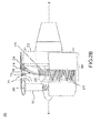
- FIG. 2A a cutaway perspective view of an aircraft propulsion system 200 having an outer barrel 202 comprising fan case 206 is shown.
- the fan case 206 may comprise a thrust reversing assembly 204.
- a thrust reversing assembly 204 may include a plurality of sleeves arranged circumferentially about the assembly 204 (e.g., as illustrated and as described herein for purposes of illustration, a sleeve 208).
- the outer barrel 202 may comprise a substantially annular structure having a radially inner surface as well as a radially outer surface.
- the propulsion system 200 may not include, as with conventional propulsion systems (e.g., system 100), a separate or isolated thrust reversing assembly 101.
- the thrust reversing assembly 204 may be incorporated in the fan case 206 (e.g., between the fan 110 at the forward end of the fan case 206 and the stator blade array 215 at the aft end of the fan case 206).
- the sleeve 208 may be stowed to cover a cascade array 210 (and which may translate aft and/or hinge radially outward from the cascade array 210 during a thrust reversing operation to expose the cascade array 210).
- the propulsion system 200 may further include one or more blocker doors 214, which may be stowed, as shown in Figure 2A , such that the cascade array 210 is covered or substantially covered by the blocker door(s) 214. Further, as shown, the outer barrel 202 may span a second axial distance 212.
- the axial span of the outer barrel 202 may be reduced by the axial span formerly occupied by the conventional thrust reversing assembly 101.
- the axial span of the outer barrel 102 may comprise the first axial distance 121 while the axial span of the outer barrel 202 may comprise the second axial distance 212.
- the first axial distance 121 may be greater than the second axial distance 212.
- the span of the outer barrel 202 may be reduced by the span of the conventional thrust reversing assembly 101 (e.g., approximately, for example from 10 inches (25.4 cm) to 40 inches (101.6 cm) and in various embodiments, about 30 inches (76.2 cm) by the elimination of the conventional thrust reversing assembly 101 from the propulsion system 200. Therefore, the outer barrel 202 may in fact be significantly shortened by the incorporation of the thrust reversing assembly 201 in the fan case 206.
- FIG. 2B a cutaway perspective view of the aircraft propulsion system 200 is shown.
- the thrust reversing assembly 204 of the aircraft propulsion system 200 is shown in a deployed configuration.
- the sleeve 208 may translate aft to expose the cascade array 210.
- a blocker door 214 may deploy radially inward within the bypass air duct 216 to block airflow in the bypass air duct 216 and turn the airflow 211 into the cascade array 210.
- the sleeve 208 may translate axially aft to expose a radially outer portion of the cascade array 210 to the slip stream while the blocker door 214 may hinge radially inward to expose a radially inner portion of the cascade array 210 to the bypass air duct 216.
- the sleeve 208 may, rather than translating aft as described above, hinge radially outward into the slip stream to expose the outer portion of the cascade array 210 to the slip stream. This configuration may increase drag.
- the blocker door 214 may turn air through the cascade array 210 to generate reverse thrust while the sleeve 208 may hinge into the slip stream to generate drag as the aircraft moves forward.
- the blocker door 214 and sleeve 208 may deploy such that they resemble an open, "v-shaped" structure, such as a shape resembling an alligator clip. While such a structure may yield increased or improved thrust reversing force, the structure may also require increased ground clearance as well as impose greater structural loads.
- the blocker door 214 may deploy, in various embodiments, at an angle within the bypass air duct 216.
- the blocker door 214 may deploy or hinge open such that a radially inward portion of the deployed blocker door 214 is situated forward of a radially outward portion of the deployed blocker door 214.
- very little impetus e.g., a slight puff of air that exerts low pressure
- may be utilized to initiate deployment of the blocker door 214 e.g., because the force of the air flowing within the bypass air duct 216 may push or drag the blocker door 214 radially inward.
- the blocker door 214 may therefore be coupled to an actuating mechanism 218, which may apply a force sufficient to overcome the force applied against the blocker door 214 by the onrush of air driven into the bypass air duct 216 by the fan 110 and against the forward surface of the blocker door 214.
- the outer barrel 202 may, even in a deployed configuration, be shortened in comparison to a conventional outer barrel 102 by the difference between the first axial distance 121 and the second axial distance 212 (in many cases, approximately 20-30 inches) and limited only by aerodynamic requirements of the duct nozzle. Therefore, as described in detail above, the outer barrel 202 may be shifted aft toward the forward edge of the wing 122 as a result of the axially reduced span of the outer barrel 202. As the outer barrel 202 is shifted aft towards the forward edge of the wing 122, the span of the pylon mounting the propulsion system 200 to the underside of the wing 122 may be likewise reduced.
- the stress placed on the (cantilevered) pylon may be reduced, first, by the reduced weight of the propulsion system 200 (having no independent thrust reversing assembly 101), and, second, by the reduced span of the pylon itself. Further, the torque on the pylon may be reduced by shortening the pylon cantilever toward the wing 122. In addition, the weight of the propulsion system 200 may be reduced, which may correspond to an increase in fuel savings and increased efficiency.
- references to "one embodiment”, “an embodiment”, “various embodiments”, etc. indicate that the embodiment described may include a particular feature, structure, or characteristic, but every embodiment may not necessarily include the particular feature, structure, or characteristic. Moreover, such phrases are not necessarily referring to the same embodiment. Further, when a particular feature, structure, or characteristic is described in connection with an embodiment, it is submitted that it is within the knowledge of one skilled in the art to affect such feature, structure, or characteristic in connection with other embodiments whether or not explicitly described. After reading the description, it will be apparent to one skilled in the relevant art(s) how to implement the disclosure in alternative embodiments.
Abstract
Description
- The present disclosure relates to a nacelle system for a jet aircraft propulsion system, and more particularly, to a thrust reversing assembly of a nacelle system.
- Jet aircraft propulsion systems (such as those that power modem commercial aircraft) typically include a structure known as a nacelle. The nacelle may include a variety of components, including an inner fixed structure ("IFS") situated substantially concentrically about an engine core. An aerodynamic structure known as an outer barrel (which may be divided into a variety of sections) may be situated substantially coaxially with and concentrically about the IFS. The radial separation between the inner surface of the outer barrel and the outer surface of the IFS may define a bypass air duct through which bypass air may flow. Further, air may flow over an outer barrel during flight. This airflow may be defined as a "slip stream."
- The nacelle may comprise a thrust reversing assembly. The thrust reversing assembly may comprise a vented structure known generally as a cascade array. During operation, a translating sleeve comprising a portion of the outer barrel may translate or shift aft to expose the cascade array to create a passage from the bypass duct through the outer barrel. A plurality of structures typically referred to as blocker doors may deploy within the bypass air duct to turn airflow in the bypass air duct through the cascade array. As airflow is turned through the cascade array, the thrust reversing assembly may generate reverse thrust.
- An aircraft propulsion system comprising a generally annular fan case defined by a fan configured to be disposed at a forward end thereof and a stator blade array configured to be disposed at an aft end thereof, a thrust reversing assembly comprising at least a portion of the fan case, the fan case comprising a generally annular cascade array, and/or a sleeve situated at least partially about the cascade array, the sleeve configured to deploy to expose the cascade array. The aircraft propulsion system may further comprise a blocker door coupled to at least one of the cascade array and an inner surface of the fan case, the blocker door configured to deploy to redirect airflow through the cascade array. The aircraft propulsion system may further comprise a blocker door configured to cover an inner surface of the cascade array such that bypass air flows through a bypass air duct defined between the blocker door and an inner fixed structure disposed radially inward of the blocker door. The aircraft propulsion system may further comprise a substantially annular outer barrel, the outer barrel comprising a fan cowl situated concentrically about the fan case, the sleeve comprising a portion of the fan cowl. The sleeve may translate axially in an aft direction to expose the cascade array. The sleeve may hinge radially outward from the cascade array to expose the cascade array. The aircraft propulsion system may further comprise a blocker door that is angled into the direction of airflow within a bypass air duct, and wherein an actuating mechanism coupled to the blocker door is capable of stowing the blocker door in response to an aborted landing.
- The subject matter of the present disclosure is particularly pointed out and distinctly claimed in the concluding portion of the specification. A more complete understanding of the present disclosure, however, may best be obtained by referring to the detailed description and claims when considered in connection with the drawing figures, wherein like numerals denote like elements.
-
Figure 1 illustrates a cutaway perspective view of a conventional jet aircraft propulsion system; -
Figure 2A illustrates, in accordance with various embodiments, a cutaway perspective view of a jet aircraft propulsion system having a fan case comprising a stowed thrust reversing assembly; and -
Figure 2B illustrates, in accordance with various embodiments, a cutaway perspective view of a jet aircraft propulsion system having a fan case comprising a deployed thrust reversing assembly. - The detailed description of exemplary embodiments herein makes reference to the accompanying drawings, which show exemplary embodiments by way of illustration. While these exemplary embodiments are described in sufficient detail to enable those skilled in the art to practice the inventions, it should be understood that other embodiments may be realized and that logical changes and adaptations in design and construction may be made in accordance with this invention and the teachings herein. Thus, the detailed description herein is presented for purposes of illustration only and not of limitation. The scope of the invention is defined by the appended claims. For example, the steps recited in any of the method or process descriptions may be executed in any order and are not necessarily limited to the order presented. Furthermore, any reference to singular includes plural embodiments, and any reference to more than one component or step may include a singular embodiment or step. Also, any reference to attached, fixed, connected or the like may include permanent, removable, temporary, partial, full and/or any other possible attachment option. Additionally, any reference to without contact (or similar phrases) may also include reduced contact or minimal contact.
- As used herein, "aft" refers to the direction associated with the tail (e.g., the back end) of an aircraft, or generally, to the direction of exhaust of the engine. As used herein, "forward" refers to the direction associated with the nose (e.g., the front end) of an aircraft, or generally, to the direction of flight.
- The nacelle may extend along the axis defined by the line marked A-A'. The portion near A may be referred to as forward and the portion near A' may be referred to as aft. In that regard, A is forward of A' and A' is aft of A.
- With reference now to
Figure 1 , a cutaway perspective view of a conventional jetaircraft propulsion system 100 is shown. Thepropulsion system 100 may generally comprise anouter barrel 102, an IFS 104, and a supporting structure orpylon 106. Theouter barrel 102 may comprise a generally annular structure defined by an outer surface situated radially outward of an inner surface. Similarly, theIFS 104 may comprise a generally annular structure defined by an outer surface situated radially outward of an inner surface thereof. - The IFS 104 may surround an engine core, which may burn a hydrocarbon fuel in the presence of oxygen to generate thrust. As described above, the inner surface of the
outer barrel 102 may be situated substantially coaxially with and concentrically about the outer surface of the IFS 104. The radial separation between the inner surface of theouter barrel 102 and the outer surface of the IFS 104 may define abypass air duct 108 through which bypass air may flow as afan 110 rotates to drive air into thebypass air duct 108. - The
outer barrel 102 may be divided into a plurality of sections. For example, theouter barrel 102 may comprise afan cowl 112 and athrust reversing assembly 101. The thrust reversing assembly may be situated aft of thefan cowl 112, and may include atranslating sleeve 114, also situated aft of thefan cowl 112. Thethrust reversing assembly 101 may also comprise a variety of components including, for example, acascade array 116, and a plurality of bypass air blocking structures orblocker doors 118. Thethrust reversing assembly 101, including the translatingsleeve 114,cascade array 116, and blocker doors 118 (shown stowed) may be situated aft of thefan cowl 112. As shown, thefan cowl 112 may be coupled to a generallyannular fan case 120 situated inward of thefan cowl 112. Thefan case 120 may extend axially, from forward to aft, substantially between thefan 110 and a stator blade array 115). - During operation, the translating
sleeve 114 may translate or shift aft to expose thecascade array 116, and the plurality ofblocker doors 118 may deploy within thebypass air duct 108 to turn airflow into and through thecascade array 116 to produce reverse thrust. The translating sleeve 114 (and more generally, the thrust reversing assembly 101) therefore contributes to the overall axial length of theouter barrel 102. For example, as shown, theouter barrel 102 may span a firstaxial distance 121. - The
propulsion system 100 is typically mounted such that it extends forward, away from anaircraft wing 122. More particularly, theouter barrel 102 and/or the engine core may be mounted to thepylon 106, which may be coupled under the wing and extend forward of the wing such that theouter barrel 102 is situated substantially forward of the forward edge of thewing 122. As described above, bypass air flows through thebypass air duct 108 during operation. However, if bypass air exits thebypass air duct 108 too near the forward edge of the wing, the bypass air may encounter the edge of thewing 122 such that turbulence is generated between bypass air exiting thebypass air duct 108 and the edge of thewing 122. Thus, theouter barrel 102, including the aft portion of thebypass air duct 108, is typically mounted sufficiently forward of the forward edge of thewing 122 to generate smooth airflow under and/or around the wing. - Therefore, as the axial span of the
outer barrel 102 increases (e.g., due to inclusion of the thrust reversing assembly 101), thepylon 106 must typically extend sufficiently forward to accommodate smooth bypass airflow. However, as thepylon 106 extends forward to mount the engine andother propulsion system 100 components to the underside of the aircraft wing 122 (including the outer barrel 102), the stress experienced by thepylon 106 as a result of the weight of thepropulsion system 100 increases as thepylon 106 is made to extend further away from thewing 122. In addition, as the span of thepylon 106 increases, the weight of thepylon 106 also increases. - Therefore, with reference to
Figure 2A , a cutaway perspective view of anaircraft propulsion system 200 having anouter barrel 202 comprisingfan case 206 is shown. Thefan case 206 may comprise athrust reversing assembly 204. As described herein, athrust reversing assembly 204 may include a plurality of sleeves arranged circumferentially about the assembly 204 (e.g., as illustrated and as described herein for purposes of illustration, a sleeve 208). Theouter barrel 202 may comprise a substantially annular structure having a radially inner surface as well as a radially outer surface. As shown, thepropulsion system 200 may not include, as with conventional propulsion systems (e.g., system 100), a separate or isolatedthrust reversing assembly 101. Rather, thethrust reversing assembly 204 may be incorporated in the fan case 206 (e.g., between thefan 110 at the forward end of thefan case 206 and thestator blade array 215 at the aft end of the fan case 206). - The
sleeve 208 may be stowed to cover a cascade array 210 (and which may translate aft and/or hinge radially outward from thecascade array 210 during a thrust reversing operation to expose the cascade array 210). Thepropulsion system 200 may further include one ormore blocker doors 214, which may be stowed, as shown inFigure 2A , such that thecascade array 210 is covered or substantially covered by the blocker door(s) 214. Further, as shown, theouter barrel 202 may span a secondaxial distance 212. - As a result of incorporation of the
thrust reversing assembly 204 in or with thefan case 206, the axial span of theouter barrel 202 may be reduced by the axial span formerly occupied by the conventionalthrust reversing assembly 101. For example, the axial span of theouter barrel 102 may comprise the firstaxial distance 121 while the axial span of theouter barrel 202 may comprise the secondaxial distance 212. The firstaxial distance 121 may be greater than the secondaxial distance 212. For example, the span of theouter barrel 202 may be reduced by the span of the conventional thrust reversing assembly 101 (e.g., approximately, for example from 10 inches (25.4 cm) to 40 inches (101.6 cm) and in various embodiments, about 30 inches (76.2 cm) by the elimination of the conventionalthrust reversing assembly 101 from thepropulsion system 200. Therefore, theouter barrel 202 may in fact be significantly shortened by the incorporation of the thrust reversing assembly 201 in thefan case 206. - With reference to
Figure 2B , a cutaway perspective view of theaircraft propulsion system 200 is shown. Thethrust reversing assembly 204 of theaircraft propulsion system 200 is shown in a deployed configuration. As shown, thesleeve 208 may translate aft to expose thecascade array 210. As thesleeve 208 translates aft, ablocker door 214 may deploy radially inward within thebypass air duct 216 to block airflow in thebypass air duct 216 and turn theairflow 211 into thecascade array 210. Thus, in various embodiments, thesleeve 208 may translate axially aft to expose a radially outer portion of thecascade array 210 to the slip stream while theblocker door 214 may hinge radially inward to expose a radially inner portion of thecascade array 210 to thebypass air duct 216. - Further, in various embodiments, the
sleeve 208 may, rather than translating aft as described above, hinge radially outward into the slip stream to expose the outer portion of thecascade array 210 to the slip stream. This configuration may increase drag. In particular, theblocker door 214 may turn air through thecascade array 210 to generate reverse thrust while thesleeve 208 may hinge into the slip stream to generate drag as the aircraft moves forward. Thus, in various embodiments, theblocker door 214 andsleeve 208 may deploy such that they resemble an open, "v-shaped" structure, such as a shape resembling an alligator clip. While such a structure may yield increased or improved thrust reversing force, the structure may also require increased ground clearance as well as impose greater structural loads. - The
blocker door 214 may deploy, in various embodiments, at an angle within thebypass air duct 216. In particular, theblocker door 214 may deploy or hinge open such that a radially inward portion of the deployedblocker door 214 is situated forward of a radially outward portion of the deployedblocker door 214. Thus, during flight, very little impetus (e.g., a slight puff of air that exerts low pressure) may be utilized to initiate deployment of the blocker door 214 (e.g., because the force of the air flowing within thebypass air duct 216 may push or drag theblocker door 214 radially inward. However, in the case of an aborted landing, it may be desirable to stow theblocker door 214 quickly to permit airflow to resume passage through thebypass air duct 216. Theblocker door 214 may therefore be coupled to anactuating mechanism 218, which may apply a force sufficient to overcome the force applied against theblocker door 214 by the onrush of air driven into thebypass air duct 216 by thefan 110 and against the forward surface of theblocker door 214. - Accordingly, the
outer barrel 202 may, even in a deployed configuration, be shortened in comparison to a conventionalouter barrel 102 by the difference between the firstaxial distance 121 and the second axial distance 212 (in many cases, approximately 20-30 inches) and limited only by aerodynamic requirements of the duct nozzle. Therefore, as described in detail above, theouter barrel 202 may be shifted aft toward the forward edge of thewing 122 as a result of the axially reduced span of theouter barrel 202. As theouter barrel 202 is shifted aft towards the forward edge of thewing 122, the span of the pylon mounting thepropulsion system 200 to the underside of thewing 122 may be likewise reduced. As a result, the stress placed on the (cantilevered) pylon may be reduced, first, by the reduced weight of the propulsion system 200 (having no independent thrust reversing assembly 101), and, second, by the reduced span of the pylon itself. Further, the torque on the pylon may be reduced by shortening the pylon cantilever toward thewing 122. In addition, the weight of thepropulsion system 200 may be reduced, which may correspond to an increase in fuel savings and increased efficiency. - The connecting lines shown in the various figures contained herein are intended to represent exemplary functional relationships and/or physical couplings between the various elements. It should be noted that many alternative or additional functional relationships or physical connections may be present in a practical system.
- The described benefits, advantages, solutions to problems, and any elements that may cause any benefit, advantage, or solution to occur or become more pronounced are not to be construed as critical, required, or essential features or elements of the inventions. The scope of the inventions is accordingly to be limited by nothing other than the appended claims, in which reference to an element in the singular is not intended to mean "one and only one" unless explicitly so stated, but rather "one or more."
- Systems, methods and apparatus are provided herein. In the detailed description herein, references to "one embodiment", "an embodiment", "various embodiments", etc., indicate that the embodiment described may include a particular feature, structure, or characteristic, but every embodiment may not necessarily include the particular feature, structure, or characteristic. Moreover, such phrases are not necessarily referring to the same embodiment. Further, when a particular feature, structure, or characteristic is described in connection with an embodiment, it is submitted that it is within the knowledge of one skilled in the art to affect such feature, structure, or characteristic in connection with other embodiments whether or not explicitly described. After reading the description, it will be apparent to one skilled in the relevant art(s) how to implement the disclosure in alternative embodiments.
- Furthermore, no element, component, or method step in the present disclosure is intended to be dedicated to the public regardless of whether the element, component, or method step is explicitly recited in the claims. No claim element herein is to be construed under the provisions of 35 U.S.C. 112(f) unless the element is expressly recited using the phrase "means for." As used herein, the terms "comprises," "comprising," or any other variation thereof, are intended to cover a non-exclusive inclusion, such that a process, method, article, or apparatus that comprises a list of elements does not include only those elements but may include other elements not expressly listed or inherent to such process, method, article, or apparatus.
Claims (11)
- An aircraft propulsion system comprising:a thrust reversing assembly (204) comprising a fan case (206), the fan case (206) comprising a cascade array (210); anda sleeve (208) situated at least partially about the cascade array (210), the sleeve (208) configured to deploy to expose the cascade array (210).
- The aircraft propulsion system of claim 1, wherein the fan case (206) is disposed between a fan (110) at a forward end thereof and a stator blade array (215) at an aft end thereof.
- The aircraft propulsion system of claim 1 or 2, further comprising a blocker door (214) coupled to at least one of the cascade array (210) and an inner surface of the fan case (206), the blocker door (214) configured to deploy to redirect airflow through the cascade array (210).
- The aircraft propulsion system of claim 3, wherein the blocker door (214) is configured to cover an inner surface of the cascade array (210) such that bypass air flows through a bypass air duct (216) defined between the blocker door (214) and an inner fixed structure disposed radially inward of the blocker door (214).
- The aircraft propulsion system of claim 1 or 2, further comprising a blocker door (214) configured to cover an inner surface of the cascade array (210) such that bypass air flows through a bypass air duct (216) defined between the blocker door (214) and an inner fixed structure disposed radially inward of the blocker door (214).
- The aircraft propulsion system of claim 3, 4 or 5, wherein the blocker door (214) is angled into the direction of airflow (211) within a bypass air duct (216), and wherein an actuating mechanism coupled to the blocker door (214) is capable of stowing the blocker door in response to an aborted landing.
- The aircraft propulsion system of claim 1 or 2, further comprising a blocker door (214) that is angled into the direction of airflow (211) within a bypass air duct (216), and wherein an actuating mechanism coupled to the blocker door (214) is capable of stowing the blocker door in response to an aborted landing.
- The aircraft propulsion system of any preceding claim, wherein the aircraft propulsion system further comprises a substantially annular outer barrel (202), the outer barrel (202) comprising a fan cowl situated concentrically about the fan case (206), the sleeve (208) comprising a portion of the fan cowl.
- The aircraft propulsion system of any preceding claim, wherein the sleeve (208) translates axially in an aft direction to expose the cascade array (210).
- The aircraft propulsion system of any of claims 1 to 8, wherein the sleeve hinges radially outward from the cascade array (210) to expose the cascade array (210).
- The aircraft propulsion system of any preceding claim, wherein said fan case (206) is a generally annular fan case (206) defined by a fan (110) configured to be disposed at a forward end thereof and a stator blade array (215) configured to be disposed at an aft end thereof, the thrust reversing assembly (204) comprising at least a portion of the fan case (206), and the cascade array (210) being a generally annular cascade array (210).
Applications Claiming Priority (1)
| Application Number | Priority Date | Filing Date | Title |
|---|---|---|---|
| US14/090,595 US9726110B2 (en) | 2013-11-26 | 2013-11-26 | Aircraft propulsion system fan case comprising thrust reversing assembly |
Publications (2)
| Publication Number | Publication Date |
|---|---|
| EP2876288A1 true EP2876288A1 (en) | 2015-05-27 |
| EP2876288B1 EP2876288B1 (en) | 2021-01-13 |
Family
ID=52015833
Family Applications (1)
| Application Number | Title | Priority Date | Filing Date |
|---|---|---|---|
| EP14194342.3A Active EP2876288B1 (en) | 2013-11-26 | 2014-11-21 | Aircraft propulsion system fan case comprising thrust reversing assembly |
Country Status (2)
| Country | Link |
|---|---|
| US (1) | US9726110B2 (en) |
| EP (1) | EP2876288B1 (en) |
Citations (5)
| Publication number | Priority date | Publication date | Assignee | Title |
|---|---|---|---|---|
| US3483702A (en) * | 1966-06-29 | 1969-12-16 | Rolls Royce | Fan thrust reverser for a jet propulsion plant |
| US3511055A (en) * | 1968-05-29 | 1970-05-12 | Rohr Corp | Thrust reverser |
| US3603090A (en) * | 1968-08-08 | 1971-09-07 | Rolls Royce | Thrust reverser for fan type jet propulsion engines |
| US4545199A (en) * | 1982-06-14 | 1985-10-08 | Rohr Industries, Inc. | Fan cascade reverser having dual blocker doors |
| US20130067884A1 (en) * | 2011-09-20 | 2013-03-21 | Jay Bhatt | Thrust reverser for a gas turbine engine |
Family Cites Families (3)
| Publication number | Priority date | Publication date | Assignee | Title |
|---|---|---|---|---|
| FR2914700B1 (en) * | 2007-04-04 | 2009-05-22 | Aircelle Sa | THRUST INVERTER FOR REACTION ENGINE |
| US8713910B2 (en) * | 2009-07-31 | 2014-05-06 | General Electric Company | Integrated thrust reverser/pylon assembly |
| US9038367B2 (en) * | 2011-09-16 | 2015-05-26 | United Technologies Corporation | Fan case thrust reverser |
-
2013
- 2013-11-26 US US14/090,595 patent/US9726110B2/en active Active
-
2014
- 2014-11-21 EP EP14194342.3A patent/EP2876288B1/en active Active
Patent Citations (5)
| Publication number | Priority date | Publication date | Assignee | Title |
|---|---|---|---|---|
| US3483702A (en) * | 1966-06-29 | 1969-12-16 | Rolls Royce | Fan thrust reverser for a jet propulsion plant |
| US3511055A (en) * | 1968-05-29 | 1970-05-12 | Rohr Corp | Thrust reverser |
| US3603090A (en) * | 1968-08-08 | 1971-09-07 | Rolls Royce | Thrust reverser for fan type jet propulsion engines |
| US4545199A (en) * | 1982-06-14 | 1985-10-08 | Rohr Industries, Inc. | Fan cascade reverser having dual blocker doors |
| US20130067884A1 (en) * | 2011-09-20 | 2013-03-21 | Jay Bhatt | Thrust reverser for a gas turbine engine |
Also Published As
| Publication number | Publication date |
|---|---|
| US9726110B2 (en) | 2017-08-08 |
| EP2876288B1 (en) | 2021-01-13 |
| US20150143795A1 (en) | 2015-05-28 |
Similar Documents
| Publication | Publication Date | Title |
|---|---|---|
| EP2937551B1 (en) | Nacelle comprising a thrust reverser | |
| US9212624B2 (en) | Aircraft nacelles, cascade assemblies having coupling catches, and thrust reverser systems | |
| US10077739B2 (en) | Dual actuation system for cascade and thrust reverser panel for an integral cascade variable area fan nozzle | |
| EP2863040A1 (en) | Thrust reverser fan ramp partially formed on aft end of fan case | |
| US10502161B2 (en) | Cascade system and apparatus | |
| US10030608B2 (en) | Variable area fan nozzle actuation system | |
| US9926884B2 (en) | Slat-thrust reverser clearance | |
| US20170283081A1 (en) | Securing a translating fanlet for an aircraft propulsion system nacelle | |
| EP3434597A1 (en) | Nacelle | |
| US20180003129A1 (en) | Radially connected cascade grids | |
| US10995701B2 (en) | Translating sleeve thrust reverser assembly | |
| US9869275B2 (en) | Single actuator variable area fan nozzle system and method | |
| EP2876288A1 (en) | Aircraft propulsion system fan case comprising thrust reversing assembly | |
| EP3705711B1 (en) | Hidden link system blocker door | |
| US9347398B2 (en) | Actuator support system and apparatus | |
| US9574519B2 (en) | Multi surface blocker door system and apparatus | |
| US9650992B2 (en) | Core cowl thrust reverser system and apparatus | |
| US10767597B2 (en) | Collapsible drag link | |
| US9856742B2 (en) | Sealing system for variable area fan nozzle | |
| US11111879B2 (en) | Thrust reverser pivot door with extended forward edge |
Legal Events
| Date | Code | Title | Description |
|---|---|---|---|
| PUAI | Public reference made under article 153(3) epc to a published international application that has entered the european phase |
Free format text: ORIGINAL CODE: 0009012 |
|
| 17P | Request for examination filed |
Effective date: 20141121 |
|
| AK | Designated contracting states |
Kind code of ref document: A1 Designated state(s): AL AT BE BG CH CY CZ DE DK EE ES FI FR GB GR HR HU IE IS IT LI LT LU LV MC MK MT NL NO PL PT RO RS SE SI SK SM TR |
|
| AX | Request for extension of the european patent |
Extension state: BA ME |
|
| R17P | Request for examination filed (corrected) |
Effective date: 20151127 |
|
| RBV | Designated contracting states (corrected) |
Designated state(s): AL AT BE BG CH CY CZ DE DK EE ES FI FR GB GR HR HU IE IS IT LI LT LU LV MC MK MT NL NO PL PT RO RS SE SI SK SM TR |
|
| STAA | Information on the status of an ep patent application or granted ep patent |
Free format text: STATUS: EXAMINATION IS IN PROGRESS |
|
| 17Q | First examination report despatched |
Effective date: 20180717 |
|
| GRAP | Despatch of communication of intention to grant a patent |
Free format text: ORIGINAL CODE: EPIDOSNIGR1 |
|
| STAA | Information on the status of an ep patent application or granted ep patent |
Free format text: STATUS: GRANT OF PATENT IS INTENDED |
|
| INTG | Intention to grant announced |
Effective date: 20200818 |
|
| GRAS | Grant fee paid |
Free format text: ORIGINAL CODE: EPIDOSNIGR3 |
|
| GRAA | (expected) grant |
Free format text: ORIGINAL CODE: 0009210 |
|
| STAA | Information on the status of an ep patent application or granted ep patent |
Free format text: STATUS: THE PATENT HAS BEEN GRANTED |
|
| AK | Designated contracting states |
Kind code of ref document: B1 Designated state(s): AL AT BE BG CH CY CZ DE DK EE ES FI FR GB GR HR HU IE IS IT LI LT LU LV MC MK MT NL NO PL PT RO RS SE SI SK SM TR |
|
| REG | Reference to a national code |
Ref country code: GB Ref legal event code: FG4D |
|
| REG | Reference to a national code |
Ref country code: CH Ref legal event code: EP |
|
| REG | Reference to a national code |
Ref country code: IE Ref legal event code: FG4D |
|
| REG | Reference to a national code |
Ref country code: DE Ref legal event code: R096 Ref document number: 602014074183 Country of ref document: DE |
|
| REG | Reference to a national code |
Ref country code: AT Ref legal event code: REF Ref document number: 1354736 Country of ref document: AT Kind code of ref document: T Effective date: 20210215 |
|
| REG | Reference to a national code |
Ref country code: AT Ref legal event code: MK05 Ref document number: 1354736 Country of ref document: AT Kind code of ref document: T Effective date: 20210113 |
|
| REG | Reference to a national code |
Ref country code: NL Ref legal event code: MP Effective date: 20210113 |
|
| REG | Reference to a national code |
Ref country code: LT Ref legal event code: MG9D |
|
| PG25 | Lapsed in a contracting state [announced via postgrant information from national office to epo] |
Ref country code: BG Free format text: LAPSE BECAUSE OF FAILURE TO SUBMIT A TRANSLATION OF THE DESCRIPTION OR TO PAY THE FEE WITHIN THE PRESCRIBED TIME-LIMIT Effective date: 20210413 Ref country code: NL Free format text: LAPSE BECAUSE OF FAILURE TO SUBMIT A TRANSLATION OF THE DESCRIPTION OR TO PAY THE FEE WITHIN THE PRESCRIBED TIME-LIMIT Effective date: 20210113 Ref country code: NO Free format text: LAPSE BECAUSE OF FAILURE TO SUBMIT A TRANSLATION OF THE DESCRIPTION OR TO PAY THE FEE WITHIN THE PRESCRIBED TIME-LIMIT Effective date: 20210413 Ref country code: LT Free format text: LAPSE BECAUSE OF FAILURE TO SUBMIT A TRANSLATION OF THE DESCRIPTION OR TO PAY THE FEE WITHIN THE PRESCRIBED TIME-LIMIT Effective date: 20210113 Ref country code: PT Free format text: LAPSE BECAUSE OF FAILURE TO SUBMIT A TRANSLATION OF THE DESCRIPTION OR TO PAY THE FEE WITHIN THE PRESCRIBED TIME-LIMIT Effective date: 20210513 Ref country code: GR Free format text: LAPSE BECAUSE OF FAILURE TO SUBMIT A TRANSLATION OF THE DESCRIPTION OR TO PAY THE FEE WITHIN THE PRESCRIBED TIME-LIMIT Effective date: 20210414 Ref country code: FI Free format text: LAPSE BECAUSE OF FAILURE TO SUBMIT A TRANSLATION OF THE DESCRIPTION OR TO PAY THE FEE WITHIN THE PRESCRIBED TIME-LIMIT Effective date: 20210113 Ref country code: HR Free format text: LAPSE BECAUSE OF FAILURE TO SUBMIT A TRANSLATION OF THE DESCRIPTION OR TO PAY THE FEE WITHIN THE PRESCRIBED TIME-LIMIT Effective date: 20210113 |
|
| PG25 | Lapsed in a contracting state [announced via postgrant information from national office to epo] |
Ref country code: LV Free format text: LAPSE BECAUSE OF FAILURE TO SUBMIT A TRANSLATION OF THE DESCRIPTION OR TO PAY THE FEE WITHIN THE PRESCRIBED TIME-LIMIT Effective date: 20210113 Ref country code: RS Free format text: LAPSE BECAUSE OF FAILURE TO SUBMIT A TRANSLATION OF THE DESCRIPTION OR TO PAY THE FEE WITHIN THE PRESCRIBED TIME-LIMIT Effective date: 20210113 Ref country code: PL Free format text: LAPSE BECAUSE OF FAILURE TO SUBMIT A TRANSLATION OF THE DESCRIPTION OR TO PAY THE FEE WITHIN THE PRESCRIBED TIME-LIMIT Effective date: 20210113 Ref country code: AT Free format text: LAPSE BECAUSE OF FAILURE TO SUBMIT A TRANSLATION OF THE DESCRIPTION OR TO PAY THE FEE WITHIN THE PRESCRIBED TIME-LIMIT Effective date: 20210113 Ref country code: SE Free format text: LAPSE BECAUSE OF FAILURE TO SUBMIT A TRANSLATION OF THE DESCRIPTION OR TO PAY THE FEE WITHIN THE PRESCRIBED TIME-LIMIT Effective date: 20210113 |
|
| PG25 | Lapsed in a contracting state [announced via postgrant information from national office to epo] |
Ref country code: IS Free format text: LAPSE BECAUSE OF FAILURE TO SUBMIT A TRANSLATION OF THE DESCRIPTION OR TO PAY THE FEE WITHIN THE PRESCRIBED TIME-LIMIT Effective date: 20210513 |
|
| REG | Reference to a national code |
Ref country code: DE Ref legal event code: R097 Ref document number: 602014074183 Country of ref document: DE |
|
| PG25 | Lapsed in a contracting state [announced via postgrant information from national office to epo] |
Ref country code: SM Free format text: LAPSE BECAUSE OF FAILURE TO SUBMIT A TRANSLATION OF THE DESCRIPTION OR TO PAY THE FEE WITHIN THE PRESCRIBED TIME-LIMIT Effective date: 20210113 Ref country code: EE Free format text: LAPSE BECAUSE OF FAILURE TO SUBMIT A TRANSLATION OF THE DESCRIPTION OR TO PAY THE FEE WITHIN THE PRESCRIBED TIME-LIMIT Effective date: 20210113 Ref country code: CZ Free format text: LAPSE BECAUSE OF FAILURE TO SUBMIT A TRANSLATION OF THE DESCRIPTION OR TO PAY THE FEE WITHIN THE PRESCRIBED TIME-LIMIT Effective date: 20210113 |
|
| PLBE | No opposition filed within time limit |
Free format text: ORIGINAL CODE: 0009261 |
|
| STAA | Information on the status of an ep patent application or granted ep patent |
Free format text: STATUS: NO OPPOSITION FILED WITHIN TIME LIMIT |
|
| PG25 | Lapsed in a contracting state [announced via postgrant information from national office to epo] |
Ref country code: ES Free format text: LAPSE BECAUSE OF FAILURE TO SUBMIT A TRANSLATION OF THE DESCRIPTION OR TO PAY THE FEE WITHIN THE PRESCRIBED TIME-LIMIT Effective date: 20210113 Ref country code: DK Free format text: LAPSE BECAUSE OF FAILURE TO SUBMIT A TRANSLATION OF THE DESCRIPTION OR TO PAY THE FEE WITHIN THE PRESCRIBED TIME-LIMIT Effective date: 20210113 Ref country code: SK Free format text: LAPSE BECAUSE OF FAILURE TO SUBMIT A TRANSLATION OF THE DESCRIPTION OR TO PAY THE FEE WITHIN THE PRESCRIBED TIME-LIMIT Effective date: 20210113 Ref country code: RO Free format text: LAPSE BECAUSE OF FAILURE TO SUBMIT A TRANSLATION OF THE DESCRIPTION OR TO PAY THE FEE WITHIN THE PRESCRIBED TIME-LIMIT Effective date: 20210113 |
|
| 26N | No opposition filed |
Effective date: 20211014 |
|
| PG25 | Lapsed in a contracting state [announced via postgrant information from national office to epo] |
Ref country code: AL Free format text: LAPSE BECAUSE OF FAILURE TO SUBMIT A TRANSLATION OF THE DESCRIPTION OR TO PAY THE FEE WITHIN THE PRESCRIBED TIME-LIMIT Effective date: 20210113 |
|
| PG25 | Lapsed in a contracting state [announced via postgrant information from national office to epo] |
Ref country code: SI Free format text: LAPSE BECAUSE OF FAILURE TO SUBMIT A TRANSLATION OF THE DESCRIPTION OR TO PAY THE FEE WITHIN THE PRESCRIBED TIME-LIMIT Effective date: 20210113 |
|
| PG25 | Lapsed in a contracting state [announced via postgrant information from national office to epo] |
Ref country code: IT Free format text: LAPSE BECAUSE OF FAILURE TO SUBMIT A TRANSLATION OF THE DESCRIPTION OR TO PAY THE FEE WITHIN THE PRESCRIBED TIME-LIMIT Effective date: 20210113 |
|
| PG25 | Lapsed in a contracting state [announced via postgrant information from national office to epo] |
Ref country code: IS Free format text: LAPSE BECAUSE OF FAILURE TO SUBMIT A TRANSLATION OF THE DESCRIPTION OR TO PAY THE FEE WITHIN THE PRESCRIBED TIME-LIMIT Effective date: 20210513 |
|
| PG25 | Lapsed in a contracting state [announced via postgrant information from national office to epo] |
Ref country code: MC Free format text: LAPSE BECAUSE OF FAILURE TO SUBMIT A TRANSLATION OF THE DESCRIPTION OR TO PAY THE FEE WITHIN THE PRESCRIBED TIME-LIMIT Effective date: 20210113 |
|
| REG | Reference to a national code |
Ref country code: CH Ref legal event code: PL |
|
| PG25 | Lapsed in a contracting state [announced via postgrant information from national office to epo] |
Ref country code: LU Free format text: LAPSE BECAUSE OF NON-PAYMENT OF DUE FEES Effective date: 20211121 Ref country code: BE Free format text: LAPSE BECAUSE OF NON-PAYMENT OF DUE FEES Effective date: 20211130 |
|
| REG | Reference to a national code |
Ref country code: BE Ref legal event code: MM Effective date: 20211130 |
|
| PG25 | Lapsed in a contracting state [announced via postgrant information from national office to epo] |
Ref country code: LI Free format text: LAPSE BECAUSE OF NON-PAYMENT OF DUE FEES Effective date: 20211130 Ref country code: CH Free format text: LAPSE BECAUSE OF NON-PAYMENT OF DUE FEES Effective date: 20211130 |
|
| PG25 | Lapsed in a contracting state [announced via postgrant information from national office to epo] |
Ref country code: IE Free format text: LAPSE BECAUSE OF NON-PAYMENT OF DUE FEES Effective date: 20211121 |
|
| PG25 | Lapsed in a contracting state [announced via postgrant information from national office to epo] |
Ref country code: HU Free format text: LAPSE BECAUSE OF FAILURE TO SUBMIT A TRANSLATION OF THE DESCRIPTION OR TO PAY THE FEE WITHIN THE PRESCRIBED TIME-LIMIT; INVALID AB INITIO Effective date: 20141121 |
|
| PG25 | Lapsed in a contracting state [announced via postgrant information from national office to epo] |
Ref country code: CY Free format text: LAPSE BECAUSE OF FAILURE TO SUBMIT A TRANSLATION OF THE DESCRIPTION OR TO PAY THE FEE WITHIN THE PRESCRIBED TIME-LIMIT Effective date: 20210113 |
|
| PGFP | Annual fee paid to national office [announced via postgrant information from national office to epo] |
Ref country code: GB Payment date: 20231019 Year of fee payment: 10 |
|
| PGFP | Annual fee paid to national office [announced via postgrant information from national office to epo] |
Ref country code: FR Payment date: 20231019 Year of fee payment: 10 Ref country code: DE Payment date: 20231019 Year of fee payment: 10 |