EP2876286A1 - Control device and control method for internal combustion engine - Google Patents
Control device and control method for internal combustion engine Download PDFInfo
- Publication number
- EP2876286A1 EP2876286A1 EP13820189.2A EP13820189A EP2876286A1 EP 2876286 A1 EP2876286 A1 EP 2876286A1 EP 13820189 A EP13820189 A EP 13820189A EP 2876286 A1 EP2876286 A1 EP 2876286A1
- Authority
- EP
- European Patent Office
- Prior art keywords
- egr
- intake
- control device
- predetermined position
- internal combustion
- Prior art date
- Legal status (The legal status is an assumption and is not a legal conclusion. Google has not performed a legal analysis and makes no representation as to the accuracy of the status listed.)
- Granted
Links
Images


Classifications
-
- F—MECHANICAL ENGINEERING; LIGHTING; HEATING; WEAPONS; BLASTING
- F02—COMBUSTION ENGINES; HOT-GAS OR COMBUSTION-PRODUCT ENGINE PLANTS
- F02B—INTERNAL-COMBUSTION PISTON ENGINES; COMBUSTION ENGINES IN GENERAL
- F02B47/00—Methods of operating engines involving adding non-fuel substances or anti-knock agents to combustion air, fuel, or fuel-air mixtures of engines
- F02B47/04—Methods of operating engines involving adding non-fuel substances or anti-knock agents to combustion air, fuel, or fuel-air mixtures of engines the substances being other than water or steam only
- F02B47/08—Methods of operating engines involving adding non-fuel substances or anti-knock agents to combustion air, fuel, or fuel-air mixtures of engines the substances being other than water or steam only the substances including exhaust gas
-
- F—MECHANICAL ENGINEERING; LIGHTING; HEATING; WEAPONS; BLASTING
- F02—COMBUSTION ENGINES; HOT-GAS OR COMBUSTION-PRODUCT ENGINE PLANTS
- F02B—INTERNAL-COMBUSTION PISTON ENGINES; COMBUSTION ENGINES IN GENERAL
- F02B37/00—Engines characterised by provision of pumps driven at least for part of the time by exhaust
- F02B37/12—Control of the pumps
- F02B37/16—Control of the pumps by bypassing charging air
-
- F—MECHANICAL ENGINEERING; LIGHTING; HEATING; WEAPONS; BLASTING
- F02—COMBUSTION ENGINES; HOT-GAS OR COMBUSTION-PRODUCT ENGINE PLANTS
- F02B—INTERNAL-COMBUSTION PISTON ENGINES; COMBUSTION ENGINES IN GENERAL
- F02B37/00—Engines characterised by provision of pumps driven at least for part of the time by exhaust
- F02B37/12—Control of the pumps
- F02B37/18—Control of the pumps by bypassing exhaust from the inlet to the outlet of turbine or to the atmosphere
-
- F—MECHANICAL ENGINEERING; LIGHTING; HEATING; WEAPONS; BLASTING
- F02—COMBUSTION ENGINES; HOT-GAS OR COMBUSTION-PRODUCT ENGINE PLANTS
- F02D—CONTROLLING COMBUSTION ENGINES
- F02D21/00—Controlling engines characterised by their being supplied with non-airborne oxygen or other non-fuel gas
- F02D21/06—Controlling engines characterised by their being supplied with non-airborne oxygen or other non-fuel gas peculiar to engines having other non-fuel gas added to combustion air
- F02D21/08—Controlling engines characterised by their being supplied with non-airborne oxygen or other non-fuel gas peculiar to engines having other non-fuel gas added to combustion air the other gas being the exhaust gas of engine
-
- F—MECHANICAL ENGINEERING; LIGHTING; HEATING; WEAPONS; BLASTING
- F02—COMBUSTION ENGINES; HOT-GAS OR COMBUSTION-PRODUCT ENGINE PLANTS
- F02D—CONTROLLING COMBUSTION ENGINES
- F02D41/00—Electrical control of supply of combustible mixture or its constituents
- F02D41/0002—Controlling intake air
- F02D41/0007—Controlling intake air for control of turbo-charged or super-charged engines
-
- F—MECHANICAL ENGINEERING; LIGHTING; HEATING; WEAPONS; BLASTING
- F02—COMBUSTION ENGINES; HOT-GAS OR COMBUSTION-PRODUCT ENGINE PLANTS
- F02D—CONTROLLING COMBUSTION ENGINES
- F02D41/00—Electrical control of supply of combustible mixture or its constituents
- F02D41/0025—Controlling engines characterised by use of non-liquid fuels, pluralities of fuels, or non-fuel substances added to the combustible mixtures
- F02D41/0047—Controlling exhaust gas recirculation [EGR]
- F02D41/0065—Specific aspects of external EGR control
- F02D41/0072—Estimating, calculating or determining the EGR rate, amount or flow
-
- F—MECHANICAL ENGINEERING; LIGHTING; HEATING; WEAPONS; BLASTING
- F02—COMBUSTION ENGINES; HOT-GAS OR COMBUSTION-PRODUCT ENGINE PLANTS
- F02M—SUPPLYING COMBUSTION ENGINES IN GENERAL WITH COMBUSTIBLE MIXTURES OR CONSTITUENTS THEREOF
- F02M26/00—Engine-pertinent apparatus for adding exhaust gases to combustion-air, main fuel or fuel-air mixture, e.g. by exhaust gas recirculation [EGR] systems
- F02M26/02—EGR systems specially adapted for supercharged engines
- F02M26/04—EGR systems specially adapted for supercharged engines with a single turbocharger
- F02M26/06—Low pressure loops, i.e. wherein recirculated exhaust gas is taken out from the exhaust downstream of the turbocharger turbine and reintroduced into the intake system upstream of the compressor
-
- F—MECHANICAL ENGINEERING; LIGHTING; HEATING; WEAPONS; BLASTING
- F02—COMBUSTION ENGINES; HOT-GAS OR COMBUSTION-PRODUCT ENGINE PLANTS
- F02M—SUPPLYING COMBUSTION ENGINES IN GENERAL WITH COMBUSTIBLE MIXTURES OR CONSTITUENTS THEREOF
- F02M26/00—Engine-pertinent apparatus for adding exhaust gases to combustion-air, main fuel or fuel-air mixture, e.g. by exhaust gas recirculation [EGR] systems
- F02M26/49—Detecting, diagnosing or indicating an abnormal function of the EGR system
-
- F—MECHANICAL ENGINEERING; LIGHTING; HEATING; WEAPONS; BLASTING
- F02—COMBUSTION ENGINES; HOT-GAS OR COMBUSTION-PRODUCT ENGINE PLANTS
- F02D—CONTROLLING COMBUSTION ENGINES
- F02D2200/00—Input parameters for engine control
- F02D2200/02—Input parameters for engine control the parameters being related to the engine
- F02D2200/04—Engine intake system parameters
- F02D2200/0402—Engine intake system parameters the parameter being determined by using a model of the engine intake or its components
-
- F—MECHANICAL ENGINEERING; LIGHTING; HEATING; WEAPONS; BLASTING
- F02—COMBUSTION ENGINES; HOT-GAS OR COMBUSTION-PRODUCT ENGINE PLANTS
- F02D—CONTROLLING COMBUSTION ENGINES
- F02D41/00—Electrical control of supply of combustible mixture or its constituents
- F02D41/0002—Controlling intake air
-
- Y—GENERAL TAGGING OF NEW TECHNOLOGICAL DEVELOPMENTS; GENERAL TAGGING OF CROSS-SECTIONAL TECHNOLOGIES SPANNING OVER SEVERAL SECTIONS OF THE IPC; TECHNICAL SUBJECTS COVERED BY FORMER USPC CROSS-REFERENCE ART COLLECTIONS [XRACs] AND DIGESTS
- Y02—TECHNOLOGIES OR APPLICATIONS FOR MITIGATION OR ADAPTATION AGAINST CLIMATE CHANGE
- Y02T—CLIMATE CHANGE MITIGATION TECHNOLOGIES RELATED TO TRANSPORTATION
- Y02T10/00—Road transport of goods or passengers
- Y02T10/10—Internal combustion engine [ICE] based vehicles
- Y02T10/12—Improving ICE efficiencies
-
- Y—GENERAL TAGGING OF NEW TECHNOLOGICAL DEVELOPMENTS; GENERAL TAGGING OF CROSS-SECTIONAL TECHNOLOGIES SPANNING OVER SEVERAL SECTIONS OF THE IPC; TECHNICAL SUBJECTS COVERED BY FORMER USPC CROSS-REFERENCE ART COLLECTIONS [XRACs] AND DIGESTS
- Y02—TECHNOLOGIES OR APPLICATIONS FOR MITIGATION OR ADAPTATION AGAINST CLIMATE CHANGE
- Y02T—CLIMATE CHANGE MITIGATION TECHNOLOGIES RELATED TO TRANSPORTATION
- Y02T10/00—Road transport of goods or passengers
- Y02T10/10—Internal combustion engine [ICE] based vehicles
- Y02T10/40—Engine management systems
Definitions
- the present invention relates to a control device and a control method for an internal combustion engine that recirculates a part of exhaust gas to an upstream side of a supercharger.
- Patent Document 1 discloses a technique that, even during execution of the EGR, controls an opening degree of a nozzle vane of a variable displacement turbocharger so that an actual boost pressure becomes a target boost pressure that is calculated on the basis of an engine speed and an engine load.
- Patent Document 1 Japanese Patent Provisional Publication Tokkai No. 2007-303380
- a control device of an internal combustion engine of the present invention comprises: an EGR ratio prediction unit that predicts, in advance, a change of an EGR ratio in a cylinder of the internal combustion engine which is caused by a change of an opening degree of an EGR control valve; and an intake control device that controls a quantity of intake air, and the intake control device is controlled on the basis of the prediction of the change of the EGR ratio by the EGR ratio prediction unit.
- the present invention in a case where the opening degree of the EGR control valve is changed, bypredicting a timing at which the EGR ratio in the cylinder changes and controlling the intake control device on the basis of this prediction, it is possible to suppress an occurrence of the torque step without distinction between a supercharging region and a non-supercharging region.
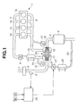
- FIG. 1 is a general system block diagram of a control device of an internal combustion engine according to the present invention.
- An internal combustion engine 1 is an engine that is mounted, as a driving source, in a vehicle such as an automobile.
- An intake passage 2 and an exhaust passage 3 are connected to each cylinder 1a of the internal combustion engine 1.
- the intake passage 2 connecting to the internal combustion engine 1 through an intake collector 4a and an intake manifold 4b is provided with an electrically controlled throttle valve 5 that is driven by an electric motor, also provided with an air flow meter 6 for detecting a quantity of intake air and an air cleaner 7 at an upstream side of the throttle valve 5.
- the exhaust passage 3 connecting to the internal combustion engine 1 through an exhaust manifold 8 is provided with an exhaust catalyst 9 such as a three-way catalyst for clean-up of exhaust gas.
- the internal combustion engine 1 is provided with a turbocharger 10 having a compressor 11 disposed in the intake passage 2 and a turbine 12 disposed in the exhaust passage 3 with these compressor 11 and turbine 12 coaxially arranged with each other.
- the compressor 11 is positioned at an upstream side with respect to the throttle valve 5, and is positioned at a downstream side with respect to the air flow meter 6.
- the turbine 12 is positioned at an upstream side with respect to the exhaust catalyst 9.
- a reference sign 13 in Fig. 1 is an intercooler provided at an upstream side of the throttle valve 5.
- a recirculation passage 14 bypassing the compressor 11 and connecting an upstream side and a downstream side of the compressor 11 is connected to the intake passage 2.
- an electrically controlled recirculation valve 15 that controls an intake flow amount in the recirculation passage 14 is installed in the recirculation passage 14.
- the recirculation valve 15 is driven by an electric motor.
- An exhaust bypass passage 16 bypassing the turbine 12 and connecting an upstream side and a downstream side of the turbine 12 is connected to the exhaust passage 3.
- an electrically controlled waste gate valve 17 that controls an exhaust flow amount in the exhaust bypass passage 16 is installed in the exhaust bypass passage 16.
- the waste gate valve 17 is driven by an electric motor. Therefore, in a supercharging region, by controlling an opening degree of the waste gate valve 17, boost pressure can be controlled. It is then possible to control the quantity of the intake air according to the opening degree of the waste gate valve 17.
- the internal combustion engine 1 is an exhaust gas recirculation (EGR) -capable engine, andanEGRpassage 20 is provided between the exhaust passage 3 and the intake passage 2.
- EGR exhaust gas recirculation
- One end of the EGR passage 20 is connected to the exhaust passage 3 in a downstream side position of the exhaust catalyst 9, and the other end of the EGR passage 20 is connected to the intake passage 2 in an upstream side position of the compressor 11 at a downstream side of the air cleaner 7.
- an electrically controlled EGR control valve 21 and an EGR cooler 22 are installed in this EGR passage 20, an electrically controlled EGR control valve 21 and an EGR cooler 22 are installed.
- the EGR control valve 21 is driven by an electric motor. Further, an opening degree of the EGR control valve 21 is controlled by a control unit 25 so as to gain a target EGR ratio according to an operating condition.
- the control unit 25 inputs a detection signal of the above-mentioned air flow meter 6, and also inputs detection signals of sensors such as a crank angle sensor 26 that detects a crank angle of a crankshaft (not shown) and an accelerator opening degree sensor 27 that detects a depression amount of an accelerator pedal (not shown).
- sensors such as a crank angle sensor 26 that detects a crank angle of a crankshaft (not shown) and an accelerator opening degree sensor 27 that detects a depression amount of an accelerator pedal (not shown).
- the control unit 25 performs controls of an ignition timing, an air-fuel ratio etc. of the internal combustion engine 1 on the basis of these detection signals.
- the control unit 25 also performs an exhaust gas recirculation control (an EGR control) that recirculates a part of the exhaust gas from the exhaust passage 3 to the intake passage 2 on the basis of the detection signals by controlling the opening degree of the EGR control valve 21.
- an EGR control an exhaust gas recirculation control
- control unit 25 controls each opening degree of the throttle valve 5, the recirculation valve 15 and the waste gate valve 17 in accordance with the operating condition.
- the opening degree of the waste gate valve 17 In the supercharging region, by controlling the opening degree of the waste gate valve 17 with the throttle valve 5 fully opened, the control is done so that fresh air required to attain an engine demand torque is supplied into the cylinder.
- the opening degree of the throttle valve 5 is controlled with the opening degree of the waste gate valve 17 set to a predetermined constant degree so that the fresh air required to attain the engine demand torque is supplied into the cylinder.
- the waste gate valve 17 controls the quantity of the intake air.
- the throttle valve 5 controls the quantity of the intake air.
- the change of the EGR ratio in the cylinder which is caused by the change of the opening degree of the EGR control valve 21, is predicted in advance, then a cooperative control to control the opening degree of the waste gate valve 17 on the basis of this prediction is executed.
- an EGR ratio in a first predetermined position in an intake system which changes at a timing T1 that is a point in advance of a timing T3 at which the EGR ratio in the cylinder changes due to the change of the opening degree of the EGR control valve 21 by a cylinder- inside intake air quantity response time ⁇ t1 (a time duration from a time point at which a target value of the waste gate valve 17 is changed up to a time point at which the fresh air quantity in the cylinder starts to change, i.e. a time duration required for the fresh air quantity in the cylinder to start to change after changing a target value of the waste gate valve 17) by the waste gate valve 17, is used for the control of the waste gate valve 17.
- the opening degree of the waste gate valve 17 is not changed at the same time (at a timing T0) as the valve open of the EGR control valve 21, but, as shown by a solid line in Fig. 2 , the opening degree of the waste gate valve 17 is changed at the timing T1 at which the EGR ratio in the first predetermined position changes by the valve open of the EGR control valve 21.
- the fresh air quantity in the cylinder can be kept constant at the start of the EGR during the steady operation in the supercharging region.
- the EGR ratio in the first predetermined position is estimated on the basis of, for instance, the quantity of the intake air, the EGR ratio at a joining point 31 between the EGR passage 20 and the intake passage 2 and a volume of a flow passage from the EGR control valve 21 to the first predetermined position.
- the first predetermined position is different depending on specifications of the intake system. For instance, in the present embodiment, in the case where the intake control device is the waste gate valve 17, the first predetermined position is almost the same position as the throttle valve 5 in the intake system. Then, the opening degree of the waste gate valve 17 is changed at a timing at which the EGR ratio changes in the position of the throttle valve 5.
- a broken line in Fig. 2 indicates a case (without the cooperative control) where the target value of the quantity of the intake air is changed, at the timing T0 of the EGR start, to the target value of the case where the EGR is carried out then the waste gate valve 17 is controlled.
- a characteristic line Ea indicates a change of an estimated EGR ratio at the joining point 31 between the EGR passage 20 and the intake passage 2
- a characteristic line Ef indicates a change of an estimated EGR ratio in the first predetermined position
- a characteristic line Ec indicates a change of an estimated EGR ratio in the cylinder.
- the change of the EGR ratio in the cylinder which is caused by the change of the opening degree of the EGR control valve 21, is predicted in advance, then a cooperative control to control the opening degree of the throttle valve 5 on the basis of this prediction is executed.
- an EGR ratio in a second predetermined position in the intake system which changes at a timing T2 that is a point in advance of the timing T3 at which the EGR ratio in the cylinder changes due to the change of the opening degree of the EGR control valve 21 by a cylinder-inside intake air quantity response time ⁇ t2 (a time duration from a time point at which a target value of the throttle valve 5 is changed up to a time point at which the fresh air quantity in the cylinder starts to change, i.e. a time duration required for the fresh air quantity in the cylinder to start to change after changing a target value of the throttle valve 5) by the throttle valve 5, is used for the control of the throttle valve 5.
- the opening degree of the throttle valve 5 is not changed at the same time (at a timing T0) as the valve open of the EGR control valve 21, but, as shown by a solid line in Fig. 3 , the opening degree of the throttle valve 5 is changed at the timing T2 at which the EGR ratio in the second predetermined position changes by the valve open of the EGR control valve 21.
- the fresh air quantity in the cylinder can be kept constant at the start of the EGR during the steady operation in the non-supercharging region.
- the EGR ratio in the secondpredeterminedposition is estimated on the basis of, for instance, the quantity of the intake air, the EGR ratio at the joining point 31 between the EGR passage 20 and the intake passage 2 and a volume of a flow passage from the EGR control valve 21 to the second predetermined position.
- the second predetermined position is almost the same position as a front side of the intake collector 4a in the intake system. Then, the opening degree of the throttle valve 5 is changed at a timing at which the EGR ratio changes in the position of the front side of the intake collector 4a.
- the second predetermined position is positioned at a cylinder 1a side with respect to the first predetermined position.
- a broken line in Fig. 3 indicates a case (without the cooperative control) where the target value of the quantity of the intake air is changed, at the timing T0 of the EGR start, to the target value of the case where the EGR is carried out then the throttle valve 5 is controlled.
- a characteristic line Es indicates a change of an estimated EGR ratio in the second predetermined position.
- first and second predetermined positions are each a system-specific value.
- a sensor that directly detects the EGR ratio could be provided at the first and second predetermined positions.
- the first and second predetermined positions could be changed according to the cylinder-inside fresh air quantity response speed.
- the first and second predetermined positions could be changed according to the engine load.
- Fig. 4 is a block diagram showing a control operation of the throttle valve 5 or the waste gate valve 17 in the first embodiment described above.
- the EGR ratio in the first predetermined position is calculated using the target EGR ratio fixed by the operating condition, the quantity of the intake air and the volume of the flow passage from the EGR control valve 21 to the first predetermined position. That is, at S1, the EGR ratio in the first predetermined position in the case where the intake control device is the waste gate valve 17 is calculated. At S2, the quantity of the fresh air to be introduced into the cylinder is calculated using the EGR ratio calculated at S1.
- the EGR ratio in the second predetermined position is calculated using the target EGR ratio fixed by the operating condition, the quantity of the intake air and the volume of the flow passage from the EGR control valve 21 to the second predetermined position. That is, at S3, the EGR ratio in the second predetermined position in the case where the intake control device is the throttle valve 5 is calculated. At S4, the quantity of the fresh air to be introduced into the cylinder is calculated using the EGR ratio calculated at S3. At S5, the intake control device is selected.
- the throttle valve 5 and the waste gate valve 17 are controlled according to the engine demand torque and the selected intake control device. That is, in the case where the selected intake control device is the waste gate valve 17, the target intake air quantity is calculated according to the engine demand torque and the fresh air quantity calculated at S2, and the waste gate valve 17 is controlled so that the quantity of the intake air becomes the calculated target intake air quantity. In the case where the selected intake control device is the throttle valve 5, the target intake air quantity is calculated according to the engine demand torque and the fresh air quantity calculated at S4, and the throttle valve 5 is controlled so that the quantity of the intake air becomes the calculated target intake air quantity.
- the change of the EGR ratio in the cylinder which is caused by the change of the opening degree of the EGR control valve 21, is predicted in advance, then the intake control device is controlled on the basis of this prediction.
- a delay time from a time point at which the opening degree of the EGR control valve 21 is changed up to a time point at which the EGR ratio in the first predetermined position changes, or a delay time from a time point at which the opening degree of the EGR control valve 21 is changed up to a time point at which the EGR ratio in the second predetermined position changes is used for the control of the intake control device.
- a first delay time (Delay Time 1) that is an elapsed time from a timing T0 at which the opening degree of the EGR control valve 21 is changed up to a timing T1 at which the EGR ratio in the first predetermined position changes is predicted.
- the opening degree of the waste gate valve 17 is not changed at the same time as the change of the opening degree of the EGR control valve 21, but after the change of the opening degree of the EGR control valve 21, a cooperative control to change the opening degree of the waste gate valve 17 is executed at the timing T1 at which this first delay time elapses.
- the first delay time (Delay Time 1) required for the EGR passing through the EGR control valve 21 to reach the first predetermined position is calculated, then the opening degree of the waste gate valve 17 is changed at the timing T1 at which this first delay time elapses.
- the fresh air quantity in the cylinder can be kept constant at the start of the EGR during the steady operation in the supercharging region.
- the first delay time is estimated on the basis, for instance, the quantity of the intake air and the volume of the flow passage from the EGR control valve 21 to the first predetermined position.
- a broken line in Fig. 5 indicates a case (without the cooperative control) where the target value of the quantity of the intake air is changed, at the timing T0 of the EGR start, to the target value of the case where the EGR is carried out then the waste gate valve 17 is controlled.
- a characteristic line Ea indicates a change of an actual EGR ratio at the joining point 31 between the EGR passage 20 and the intake passage 2
- a characteristic line Ef indicates a change of an actual EGR ratio in the first predetermined position
- a characteristic line Ec indicates a change of an actual EGR ratio in the cylinder.
- a second delay time (Delay Time 2) that is an elapsed time from a timing T0 at which the opening degree of the EGR control valve 21 is changed up to a timing T2 at which the EGR ratio in the second predetermined position changes is predicted.
- the opening degree of the throttle valve 5 is not changed at the same time as the change of the opening degree of the EGR control valve 21, but after the change of the opening degree of the EGR control valve 21, a cooperative control to change the opening degree of the throttle valve 5 is executed at the timing T2 at which this second delay time elapses.
- the second delay time (Delay Time 2) required for the EGR passing through the EGR control valve 21 to reach the second predetermined position is calculated, then the opening degree of the throttle valve 5 is changed at the timing T2 at which this second delay time elapses.
- the fresh air quantity in the cylinder can be kept constant at the start of the EGR during the steady operation in the non-supercharging region.
- the second delay time is estimated on the basis, for instance, the quantity of the intake air and the volume of the flow passage from the EGR control valve 21 to the second predetermined position.
- the second delay time corresponds to a time required for the EGR passing through the EGR control valve 21 to reach the second predetermined position that is positioned at a cylinder 1a side with respect to the first predetermined position.
- the second delay time is a value that is greater than the first delay time.
- a broken line in Fig. 6 indicates a case (without the cooperative control) where the target value of the quantity of the intake air is changed, at the timing T0 of the EGR start, to the target value of the case where the EGR is carried out then the throttle valve 5 is controlled.
- a characteristic line Es indicates a change of an actual EGR ratio in the second predetermined position.
- Fig. 7 is a block diagram showing a control operation of the throttle valve 5 or the waste gate valve 17 in the second embodiment described above.
- the first delay time from the time point at which the EGR control valve 21 is driven up to the time point at which the EGR ratio in the first predetermined position changes is calculated using the quantity of the intake air and the volume of the flow passage from the EGR control valve 21 to the first predetermined position.
- the second delay time from the time point at which the EGR control valve 21 is driven up to the time point at which the EGR ratio in the second predetermined position changes is calculated using the quantity of the intake air and the volume of the flow passage from the EGR control valve 21 to the second predetermined position.
- the intake control device is selected.
- the target intake air quantity is calculated according to the engine demand torque and the opening degree of the EGR control valve 21, and the throttle valve 5 and the waste gate valve 17 are controlled so that the quantity of the intake air becomes the calculated target intake air quantity.
- the opening degree of the waste gate valve 17 is controlled so as to attain the target intake air quantity calculated at S14 at the timing at which time is delayed by the first delay time calculated at S11 after the EGR control valve 21 is driven.
- the opening degree of the throttle valve 5 is controlled so as to attain the target intake air quantity calculated at S14 at the timing at which time is delayed by the second delay time calculated at S12 after the EGR control valve 21 is driven.
- the first delay time and the second delay time in this second embodiment are calculated according to the quantity of the intake air, the volume of the flow passage from the EGR control valve 21 to the first predetermined position and the volume of the flow passage from the EGR control valve 21 to the second predetermined position.
- these first and second delay times could be calculated from the engine load, an engine speed and an intake flow velocity.
- a delay time calculation map as shown in Fig. 8 , in which the engine load, the engine speed, the intake flow velocity and the delay time are associated with each other, is previously prepared as experimental data, and the delay time could be calculated with reference to this delay time calculation map.
- the delay time is set so that the greater the engine load, the smaller the delay time, and the greater the engine speed, the smaller the delay time, also the higher the intake flow velocity, the smaller the delay time.
- each opening degree of the throttle valve 5, the waste gate valve 17 and the EGR control valve 21 is changed to the target opening degree with almost no response delay.
Landscapes
- Engineering & Computer Science (AREA)
- Chemical & Material Sciences (AREA)
- Combustion & Propulsion (AREA)
- Mechanical Engineering (AREA)
- General Engineering & Computer Science (AREA)
- Output Control And Ontrol Of Special Type Engine (AREA)
- Combined Controls Of Internal Combustion Engines (AREA)
- Supercharger (AREA)
- Exhaust-Gas Circulating Devices (AREA)
Abstract
Description
- The present invention relates to a control device and a control method for an internal combustion engine that recirculates a part of exhaust gas to an upstream side of a supercharger.
- There has been known a technique that, by performing so-called EGR which introduces exhaust gas into an intake system in accordance with an operating condition, improves exhaust performance and increases fuel economy of an internal combustion engine.
- For instance,
Patent Document 1 discloses a technique that, even during execution of the EGR, controls an opening degree of a nozzle vane of a variable displacement turbocharger so that an actual boost pressure becomes a target boost pressure that is calculated on the basis of an engine speed and an engine load. - In such a technique of
Patent Document 1, however, although a steady torque demand can be satisfied when introducing the EGR from an upstream side with respect to a compressor housing of the turbocharger, there is a risk that a torque step caused by a transient change of a quantity of intake air in a cylinder which occurs upon start and stop of the EGR can not be avoided. - Patent Document 1 : Japanese Patent Provisional Publication Tokkai No.
2007-303380 - Thus, a control device of an internal combustion engine of the present invention comprises: an EGR ratio prediction unit that predicts, in advance, a change of an EGR ratio in a cylinder of the internal combustion engine which is caused by a change of an opening degree of an EGR control valve; and an intake control device that controls a quantity of intake air, and the intake control device is controlled on the basis of the prediction of the change of the EGR ratio by the EGR ratio prediction unit.
- According to the present invention, in a case where the opening degree of the EGR control valve is changed, bypredicting a timing at which the EGR ratio in the cylinder changes and controlling the intake control device on the basis of this prediction, it is possible to suppress an occurrence of the torque step without distinction between a supercharging region and a non-supercharging region.
-
- [
Fig. 1 ]
Fig. 1 is a general system block diagram of a control device of an internal combustion engine according to the present invention. - [
Fig. 2 ]
Fig. 2 is a timing chart showing each status at EGR start in a supercharging region according to a first embodiment. - [
Fig. 3 ]
Fig. 3 is a timing chart showing each status at EGR start in a non-supercharging region according to the first embodiment. - [
Fig. 4 ]
Fig. 4 is a block diagram showing a control operation according to the first embodiment. - [
Fig. 5 ]
Fig. 5 is a timing chart showing each status at EGR start in the supercharging region according to a second embodiment. - [
Fig. 6 ]
Fig. 6 is a timing chart showing each status at EGR start in the non-supercharging region according to the second embodiment. - [
Fig. 7 ]
Fig. 7 is a block diagram showing a control operation according to the second embodiment. - [
Fig. 8 ]
Fig. 8 is a delay time calculation map. - In the following description, embodiments of the present invention will be explained on the basis of the drawings.
Fig. 1 is a general system block diagram of a control device of an internal combustion engine according to the present invention. - An
internal combustion engine 1 is an engine that is mounted, as a driving source, in a vehicle such as an automobile. Anintake passage 2 and anexhaust passage 3 are connected to eachcylinder 1a of theinternal combustion engine 1. Theintake passage 2 connecting to theinternal combustion engine 1 through an intake collector 4a and an intake manifold 4b is provided with an electrically controlledthrottle valve 5 that is driven by an electric motor, also provided with anair flow meter 6 for detecting a quantity of intake air and an air cleaner 7 at an upstream side of thethrottle valve 5. Theexhaust passage 3 connecting to theinternal combustion engine 1 through anexhaust manifold 8 is provided with anexhaust catalyst 9 such as a three-way catalyst for clean-up of exhaust gas. - Further, the
internal combustion engine 1 is provided with aturbocharger 10 having acompressor 11 disposed in theintake passage 2 and aturbine 12 disposed in theexhaust passage 3 with thesecompressor 11 andturbine 12 coaxially arranged with each other. Thecompressor 11 is positioned at an upstream side with respect to thethrottle valve 5, and is positioned at a downstream side with respect to theair flow meter 6. Theturbine 12 is positioned at an upstream side with respect to theexhaust catalyst 9. Here, areference sign 13 inFig. 1 is an intercooler provided at an upstream side of thethrottle valve 5. - A
recirculation passage 14 bypassing thecompressor 11 and connecting an upstream side and a downstream side of thecompressor 11 is connected to theintake passage 2. In therecirculation passage 14, an electrically controlledrecirculation valve 15 that controls an intake flow amount in therecirculation passage 14 is installed. Therecirculation valve 15 is driven by an electric motor. As therecirculation valve 15, it is possible to use a so-called check valve that opens only when pressure at the downstream side of thecompressor 11 becomes a predetermined pressure or higher. - An
exhaust bypass passage 16 bypassing theturbine 12 and connecting an upstream side and a downstream side of theturbine 12 is connected to theexhaust passage 3. In theexhaust bypass passage 16, an electrically controlledwaste gate valve 17 that controls an exhaust flow amount in theexhaust bypass passage 16 is installed. Thewaste gate valve 17 is driven by an electric motor. Therefore, in a supercharging region, by controlling an opening degree of thewaste gate valve 17, boost pressure can be controlled. It is then possible to control the quantity of the intake air according to the opening degree of thewaste gate valve 17. - The
internal combustion engine 1 is an exhaust gas recirculation (EGR) -capable engine, andanEGRpassage 20 is provided between theexhaust passage 3 and theintake passage 2. One end of the EGRpassage 20 is connected to theexhaust passage 3 in a downstream side position of theexhaust catalyst 9, and the other end of theEGR passage 20 is connected to theintake passage 2 in an upstream side position of thecompressor 11 at a downstream side of the air cleaner 7. In thisEGR passage 20, an electrically controlledEGR control valve 21 and anEGR cooler 22 are installed. The EGRcontrol valve 21 is driven by an electric motor. Further, an opening degree of theEGR control valve 21 is controlled by acontrol unit 25 so as to gain a target EGR ratio according to an operating condition. - The
control unit 25 inputs a detection signal of the above-mentionedair flow meter 6, and also inputs detection signals of sensors such as acrank angle sensor 26 that detects a crank angle of a crankshaft (not shown) and an acceleratoropening degree sensor 27 that detects a depression amount of an accelerator pedal (not shown). - The
control unit 25 performs controls of an ignition timing, an air-fuel ratio etc. of theinternal combustion engine 1 on the basis of these detection signals. Thecontrol unit 25 also performs an exhaust gas recirculation control (an EGR control) that recirculates a part of the exhaust gas from theexhaust passage 3 to theintake passage 2 on the basis of the detection signals by controlling the opening degree of theEGR control valve 21. - Further, the
control unit 25 controls each opening degree of thethrottle valve 5, therecirculation valve 15 and thewaste gate valve 17 in accordance with the operating condition. - In the supercharging region, by controlling the opening degree of the
waste gate valve 17 with thethrottle valve 5 fully opened, the control is done so that fresh air required to attain an engine demand torque is supplied into the cylinder. As for a non-supercharging region, the opening degree of thethrottle valve 5 is controlled with the opening degree of thewaste gate valve 17 set to a predetermined constant degree so that the fresh air required to attain the engine demand torque is supplied into the cylinder. - That is, in the supercharging region, as an intake control device, the
waste gate valve 17 controls the quantity of the intake air. In the non-supercharging region, as the intake control device, thethrottle valve 5 controls the quantity of the intake air. - In such
internal combustion engine 1, for instance, in a case where the EGR is started in the supercharging region, in order for theinternal combustion engine 1 to attain the demand torque, it is necessary to control thewaste gate valve 17 so that a quantity of the fresh air in the cylinder where the fresh air is lacking is supplied or compensated by the introduction of the EGR. - However, there occurs a response delay from a time point at which the opening degree of the
EGR control valve 21 is changed up to a time point at which a change of an EGR ratio in the cylinder actually appears. Because of this, if a target value of the quantity of the intake air is changed, at a timing of the EGR start, to a target value of a case where the EGR is carried out, the quantity of the fresh air (a cylinder intake fresh air quantity) in the cylinder changes before the EGR ratio in the cylinder changes. A torque step thus occurs, and this causes deterioration in drivability. - Therefore, in the case where the EGR is started or stopped in the supercharging region, the change of the EGR ratio in the cylinder, which is caused by the change of the opening degree of the
EGR control valve 21, is predicted in advance, then a cooperative control to control the opening degree of thewaste gate valve 17 on the basis of this prediction is executed. - For instance, in a case where the EGR is started during a steady operation (during an operation in which the engine demand torque is constant) in the supercharging region, as shown in
Fig. 2 , an EGR ratio in a first predetermined position in an intake system, which changes at a timing T1 that is a point in advance of a timing T3 at which the EGR ratio in the cylinder changes due to the change of the opening degree of theEGR control valve 21 by a cylinder- inside intake air quantity response time Δt1 (a time duration from a time point at which a target value of thewaste gate valve 17 is changed up to a time point at which the fresh air quantity in the cylinder starts to change, i.e. a time duration required for the fresh air quantity in the cylinder to start to change after changing a target value of the waste gate valve 17) by thewaste gate valve 17, is used for the control of thewaste gate valve 17. - That is to say, in the case where the EGR is started in the supercharging region, the opening degree of the
waste gate valve 17 is not changed at the same time (at a timing T0) as the valve open of theEGR control valve 21, but, as shown by a solid line inFig. 2 , the opening degree of thewaste gate valve 17 is changed at the timing T1 at which the EGR ratio in the first predetermined position changes by the valve open of theEGR control valve 21. With this control, the fresh air quantity in the cylinder can be kept constant at the start of the EGR during the steady operation in the supercharging region. - The EGR ratio in the first predetermined position is estimated on the basis of, for instance, the quantity of the intake air, the EGR ratio at a joining
point 31 between theEGR passage 20 and theintake passage 2 and a volume of a flow passage from theEGR control valve 21 to the first predetermined position. - Further, the first predetermined position is different depending on specifications of the intake system. For instance, in the present embodiment, in the case where the intake control device is the
waste gate valve 17, the first predetermined position is almost the same position as thethrottle valve 5 in the intake system. Then, the opening degree of thewaste gate valve 17 is changed at a timing at which the EGR ratio changes in the position of thethrottle valve 5. - Here, a broken line in
Fig. 2 indicates a case (without the cooperative control) where the target value of the quantity of the intake air is changed, at the timing T0 of the EGR start, to the target value of the case where the EGR is carried out then thewaste gate valve 17 is controlled. In addition, inFig. 2 , a characteristic line Ea indicates a change of an estimated EGR ratio at the joiningpoint 31 between theEGR passage 20 and theintake passage 2, a characteristic line Ef indicates a change of an estimated EGR ratio in the first predetermined position, and a characteristic line Ec indicates a change of an estimated EGR ratio in the cylinder. - On the other hand, in such
internal combustion engine 1, for instance, in a case where the EGR is started in the non-supercharging region, in order for theinternal combustion engine 1 to attain the demand torque, it is necessary to control thethrottle valve 5 so that a quantity of the fresh air in the cylinder where the fresh air is lacking is supplied or compensated by the introduction of the EGR. Also in this case, if the target value of the quantity of the intake air is changed, at the timing of the EGR start, to the target value of the case where the EGR is carried out, the opening degree of thethrottle valve 5 is changed toward the valve open at the timing of the EGR start, and the quantity of the fresh air (the cylinder intake fresh air quantity) in the cylinder changes before the EGR ratio in the cylinder changes. A torque step thus occurs, and this causes deterioration in drivability. - Therefore, in the case where the EGR is started or stopped in the non-supercharging region, the change of the EGR ratio in the cylinder, which is caused by the change of the opening degree of the
EGR control valve 21, is predicted in advance, then a cooperative control to control the opening degree of thethrottle valve 5 on the basis of this prediction is executed. - For instance, in a case where the EGR is started during a steady operation (during an operation in which the engine demand torque is constant) in the non-supercharging region, as shown in
Fig. 3 , an EGR ratio in a second predetermined position in the intake system, which changes at a timing T2 that is a point in advance of the timing T3 at which the EGR ratio in the cylinder changes due to the change of the opening degree of theEGR control valve 21 by a cylinder-inside intake air quantity response time Δt2 (a time duration from a time point at which a target value of thethrottle valve 5 is changed up to a time point at which the fresh air quantity in the cylinder starts to change, i.e. a time duration required for the fresh air quantity in the cylinder to start to change after changing a target value of the throttle valve 5) by thethrottle valve 5, is used for the control of thethrottle valve 5. - That is to say, in the case where the EGR is started in the non-supercharging region, the opening degree of the
throttle valve 5 is not changed at the same time (at a timing T0) as the valve open of theEGR control valve 21, but, as shown by a solid line inFig. 3 , the opening degree of thethrottle valve 5 is changed at the timing T2 at which the EGR ratio in the second predetermined position changes by the valve open of theEGR control valve 21. With this control, the fresh air quantity in the cylinder can be kept constant at the start of the EGR during the steady operation in the non-supercharging region. - The EGR ratio in the secondpredeterminedposition is estimated on the basis of, for instance, the quantity of the intake air, the EGR ratio at the joining
point 31 between theEGR passage 20 and theintake passage 2 and a volume of a flow passage from theEGR control valve 21 to the second predetermined position. - In the present embodiment, in the case where the intake control device is the
throttle valve 5, the second predetermined position is almost the same position as a front side of the intake collector 4a in the intake system. Then, the opening degree of thethrottle valve 5 is changed at a timing at which the EGR ratio changes in the position of the front side of the intake collector 4a. - Here, since the cylinder-inside intake air quantity response time Δt2 by the
throttle valve 5 is shorter than the cylinder-inside intake air quantity response time Δt1 by thewaste gate valve 17, the second predetermined position is positioned at acylinder 1a side with respect to the first predetermined position. - A broken line in
Fig. 3 indicates a case (without the cooperative control) where the target value of the quantity of the intake air is changed, at the timing T0 of the EGR start, to the target value of the case where the EGR is carried out then thethrottle valve 5 is controlled. In addition, inFig. 3 , a characteristic line Es indicates a change of an estimated EGR ratio in the second predetermined position. - Inthismanner, in the case where the opening degree of the
EGR control valve 21 is changed, the timing at which the EGR ratio in the cylinder changes is predicted, thethrottle valve 5 and thewaste gate valve 17 that are the intake control devices are controlled on the basis of this prediction, and the quantity of the intake air is controlled so that the fresh air quantity in the cylinder does not change upon the change of the opening degree of theEGR control valve 21. With this control, an EGR transport route to the cylinder becomes relatively long by the fact that the EGR is introduced to the upstream side of thecompressor 11 of theturbocharger 10. Thus, even in the system having possibility that the response delay from the time point at which the opening degree of theEGR control valve 21 is changed up to the time point at which the change of the EGR ratio in the cylinder appears becomes relatively long, it is possible to suppress the occurrence of the torque step upon the change of the opening degree of theEGR control valve 21 without distinction between the supercharging region and the non-supercharging region. - Here, the above first and second predetermined positions are each a system-specific value. In a case where each of these values does not change, a sensor that directly detects the EGR ratio could be provided at the first and second predetermined positions.
- Further, in a case where the response time from the time point at which the target opening degree of the
throttle valve 5 or thewaste gate valve 17 is changed up to the time point at which the fresh air quantity in the cylinder starts to change changes and a cylinder-inside fresh air quantity response speed changes , the first and second predetermined positions could be changed according to the cylinder-inside fresh air quantity response speed. For instance, in a case where the cylinder-inside fresh air quantity response speed changes by an engine load, the first and second predetermined positions could be changed according to the engine load. -
Fig. 4 is a block diagram showing a control operation of thethrottle valve 5 or thewaste gate valve 17 in the first embodiment described above. - At S1, the EGR ratio in the first predetermined position is calculated using the target EGR ratio fixed by the operating condition, the quantity of the intake air and the volume of the flow passage from the
EGR control valve 21 to the first predetermined position. That is, at S1, the EGR ratio in the first predetermined position in the case where the intake control device is thewaste gate valve 17 is calculated. At S2, the quantity of the fresh air to be introduced into the cylinder is calculated using the EGR ratio calculated at S1. - At S3, the EGR ratio in the second predetermined position is calculated using the target EGR ratio fixed by the operating condition, the quantity of the intake air and the volume of the flow passage from the
EGR control valve 21 to the second predetermined position. That is, at S3, the EGR ratio in the second predetermined position in the case where the intake control device is thethrottle valve 5 is calculated. At S4, the quantity of the fresh air to be introduced into the cylinder is calculated using the EGR ratio calculated at S3. At S5, the intake control device is selected. - At S6, the
throttle valve 5 and thewaste gate valve 17 are controlled according to the engine demand torque and the selected intake control device. That is, in the case where the selected intake control device is thewaste gate valve 17, the target intake air quantity is calculated according to the engine demand torque and the fresh air quantity calculated at S2, and thewaste gate valve 17 is controlled so that the quantity of the intake air becomes the calculated target intake air quantity. In the case where the selected intake control device is thethrottle valve 5, the target intake air quantity is calculated according to the engine demand torque and the fresh air quantity calculated at S4, and thethrottle valve 5 is controlled so that the quantity of the intake air becomes the calculated target intake air quantity. - Next, a second embodiment of the present invention will be explained. Also in the second embodiment, in the same way as the first embodiment, the change of the EGR ratio in the cylinder, which is caused by the change of the opening degree of the
EGR control valve 21, is predicted in advance, then the intake control device is controlled on the basis of this prediction. However, in the second embodiment, a delay time from a time point at which the opening degree of theEGR control valve 21 is changed up to a time point at which the EGR ratio in the first predetermined position changes, or a delay time from a time point at which the opening degree of theEGR control valve 21 is changed up to a time point at which the EGR ratio in the second predetermined position changes, is used for the control of the intake control device. - For instance, in the case where the EGR is started during the steady operation (during the operation in which the engine demand torque is constant) in the supercharging region, as shown in
Fig. 5 , a first delay time (Delay Time 1) that is an elapsed time from a timing T0 at which the opening degree of theEGR control valve 21 is changed up to a timing T1 at which the EGR ratio in the first predetermined position changes is predicted. Then, the opening degree of thewaste gate valve 17 is not changed at the same time as the change of the opening degree of theEGR control valve 21, but after the change of the opening degree of theEGR control valve 21, a cooperative control to change the opening degree of thewaste gate valve 17 is executed at the timing T1 at which this first delay time elapses. - Put another way, in the case where the EGR is started in the supercharging region, the first delay time (Delay Time 1) required for the EGR passing through the
EGR control valve 21 to reach the first predetermined position is calculated, then the opening degree of thewaste gate valve 17 is changed at the timing T1 at which this first delay time elapses. With this control, the fresh air quantity in the cylinder can be kept constant at the start of the EGR during the steady operation in the supercharging region. - The first delay time is estimated on the basis, for instance, the quantity of the intake air and the volume of the flow passage from the
EGR control valve 21 to the first predetermined position. - Here, a broken line in
Fig. 5 indicates a case (without the cooperative control) where the target value of the quantity of the intake air is changed, at the timing T0 of the EGR start, to the target value of the case where the EGR is carried out then thewaste gate valve 17 is controlled. Inaddition, inFig. 5, a characteristic line Ea indicates a change of an actual EGR ratio at the joiningpoint 31 between theEGR passage 20 and theintake passage 2 , a characteristic line Ef indicates a change of an actual EGR ratio in the first predetermined position, and a characteristic line Ec indicates a change of an actual EGR ratio in the cylinder. - Furthermore, for instance, in the case where the EGR is started during the steady operation (during the operation in which the engine demand torque is constant) in the non-supercharging region, as shown in
Fig. 6 , a second delay time (Delay Time 2) that is an elapsed time from a timing T0 at which the opening degree of theEGR control valve 21 is changed up to a timing T2 at which the EGR ratio in the second predetermined position changes is predicted. Then, the opening degree of thethrottle valve 5 is not changed at the same time as the change of the opening degree of theEGR control valve 21, but after the change of the opening degree of theEGR control valve 21, a cooperative control to change the opening degree of thethrottle valve 5 is executed at the timing T2 at which this second delay time elapses. - Put another way, in the case where the EGR is started in the non-supercharging region, the second delay time (Delay Time 2) required for the EGR passing through the
EGR control valve 21 to reach the second predetermined position is calculated, then the opening degree of thethrottle valve 5 is changed at the timing T2 at which this second delay time elapses. With this control, the fresh air quantity in the cylinder can be kept constant at the start of the EGR during the steady operation in the non-supercharging region. - The second delay time is estimated on the basis, for instance, the quantity of the intake air and the volume of the flow passage from the
EGR control valve 21 to the second predetermined position. - Here, the second delay time corresponds to a time required for the EGR passing through the
EGR control valve 21 to reach the second predetermined position that is positioned at acylinder 1a side with respect to the first predetermined position. The second delay time is a value that is greater than the first delay time. - A broken line in
Fig. 6 indicates a case (without the cooperative control) where the target value of the quantity of the intake air is changed, at the timing T0 of the EGR start, to the target value of the case where the EGR is carried out then thethrottle valve 5 is controlled. In addition, inFig. 6 , a characteristic line Es indicates a change of an actual EGR ratio in the second predetermined position. -
Fig. 7 is a block diagram showing a control operation of thethrottle valve 5 or thewaste gate valve 17 in the second embodiment described above. - At S11, the first delay time from the time point at which the
EGR control valve 21 is driven up to the time point at which the EGR ratio in the first predetermined position changes is calculated using the quantity of the intake air and the volume of the flow passage from theEGR control valve 21 to the first predetermined position. - At S12, the second delay time from the time point at which the
EGR control valve 21 is driven up to the time point at which the EGR ratio in the second predetermined position changes is calculated using the quantity of the intake air and the volume of the flow passage from theEGR control valve 21 to the second predetermined position. At S13, the intake control device is selected. - At S14, the target intake air quantity is calculated according to the engine demand torque and the opening degree of the
EGR control valve 21, and thethrottle valve 5 and thewaste gate valve 17 are controlled so that the quantity of the intake air becomes the calculated target intake air quantity. - Then, in the case where the intake control device is the
waste gate valve 17, upon the EGR start, at S15, the opening degree of thewaste gate valve 17 is controlled so as to attain the target intake air quantity calculated at S14 at the timing at which time is delayed by the first delay time calculated at S11 after theEGR control valve 21 is driven. - Further, in the case where the intake control device is the
throttle valve 5, upon the EGR start, at S16, the opening degree of thethrottle valve 5 is controlled so as to attain the target intake air quantity calculated at S14 at the timing at which time is delayed by the second delay time calculated at S12 after theEGR control valve 21 is driven. - Also in the second embodiment as described above, since the quantity of the intake air is controlled so that the fresh air quantity in the cylinder does not change upon the change of the opening degree of the
EGR control valve 21, in the same way as the first embodiment, it is possible to suppress the occurrence of the torque step upon the change of the opening degree of theEGR control valve 21 without distinction between the supercharging region and the non-supercharging region. - Here, the first delay time and the second delay time in this second embodiment are calculated according to the quantity of the intake air, the volume of the flow passage from the
EGR control valve 21 to the first predetermined position and the volume of the flow passage from theEGR control valve 21 to the second predetermined position. However, these first and second delay times could be calculated from the engine load, an engine speed and an intake flow velocity. In this case, although the delay time can be calculated as necessitated from the engine load, the engine speed and the intake flow velocity, a delay time calculation map as shown inFig. 8 , in which the engine load, the engine speed, the intake flow velocity and the delay time are associated with each other, is previously prepared as experimental data, and the delay time could be calculated with reference to this delay time calculation map. In thisFig. 8 , the delay time is set so that the greater the engine load, the smaller the delay time, and the greater the engine speed, the smaller the delay time, also the higher the intake flow velocity, the smaller the delay time. - In each embodiment described above, when the target value is changed, each opening degree of the
throttle valve 5, thewaste gate valve 17 and theEGR control valve 21 is changed to the target opening degree with almost no response delay.
Claims (11)
- A control device of an internal combustion engine having a supercharger arranged at an upstream side of a throttle valve, an EGR passage recirculating, as EGR, a part of exhaust gas from an upstream side with respect to the supercharger and an EGR control valve disposed at some midpoint in the EGR passage, the control device comprising:an EGR ratio prediction unit that predicts , in advance, a change of an EGR ratio in a cylinder of the internal combustion engine which is caused by a change of an opening degree of the EGR control valve; andan intake control device that controls a quantity of intake air, andthe intake control device being controlled on the basis of the prediction by the EGR ratio prediction unit.
- The control device of the internal combustion engine as claimed in claim 1, wherein:the EGR ratio prediction unit predicts the EGR ratio in a predetermined position in an intake system which is a downstream-side position with respect to a joining point between the EGR passage and an intake passage.
- The control device of the internal combustion engine as claimed in claim 1 or 2, wherein:the EGR ratio prediction unit predicts the EGR ratio in a predetermined position in an intake system, the EGR ratio in the predetermined position changing at a timing that is a time point in advance of a timing at which the EGR ratio in the cylinder changes due to the change of the opening degree of the EGR control valve by an intake control device response time required for a quantity of fresh air in the cylinder to start to change after changing the quantity of the intake air by the intake control device, andthe intake control device is controlled on the basis of the EGR ratio in the predetermined position.
- The control device of the internal combustion engine as claimed in claim 1, wherein:the EGR ratio prediction unit predicts a delay time that is required for the EGR ratio in a predetermined position in an intake system which is a downstream-side position with respect to a joining point between the EGR passage and an intake passage to change after changing the opening degree of the EGR control valve.
- The control device of the internal combustion engine as claimed in claim 1 or 4, wherein:the EGR ratio prediction unit predicts a delay time that is required for the EGR ratio in a predetermined position in an intake system, the EGR ratio in the predetermined position changing at a timing that is a time point in advance of a timing at which the EGR ratio in the cylinder changes due to the change of the opening degree of the EGR control valve by an intake control device response time required for a quantity of fresh air in the cylinder to start to change after changing the quantity of the intake air by the intake control device, to change after changing the opening degree of the EGR control valve, andwhen changing the opening degree of the EGR control valve, a target value of the intake control device is changed after a lapse of the delay time from the change of the opening degree of the EGR control valve.
- The control device of the internal combustion engine as claimed in any one of the preceding claims 2 to 5, wherein:a plurality of the intake control devices are provided, andthe predetermined position is set according to the intake control devices.
- The control device of the internal combustion engine as claimed in any one of the preceding claims 2 to 6, wherein:the predetermined position is changed according to the time required for the quantity of the fresh air in the cylinder to start to change after changing a target value of the intake control device.
- The control device of the internal combustion engine as claimed in any one of the preceding claims 1 to 7, wherein:the supercharger is a device that drives a compressor disposed in the intake passage by a turbine disposed in an exhaust passage,a bypass passage bypassing the turbine, in which a waste gate valve that controls an exhaust flow amount is installed, is connected to the exhaust passage, andin a case where the waste gate valve is used as the intake control device, as compared with a case where the throttle valve is used as the intake control device, the predetermined position is shifted to an upstream side.
- The control device of the internal combustion engine as claimed in claim 2 or 3, wherein:the EGR ratio in the predetermined posit ion is estimated on the basis of the quantity of the intake air, the EGR ratio at the joining point between the EGR passage and the intake passage and a volume of a flow passage from the EGR control valve to the predetermined position.
- The control device of the internal combustion engine as claimed in claim 2 or 3, wherein:the EGR ratio in the predetermined position is detected by an EGR ratio-detectable sensor.
- A method for controlling an internal combustion engine comprising:predicting, in advance, a change of an EGR ratio in a cylinder of the internal combustion engine which is caused by a change of an opening degree of an EGR control valve disposed in an EGR passage recirculating, as EGR, a part of exhaust gas from an upstream side with respect to a supercharger arranged at an upstream side of a throttle valve; andcontrolling an intake control device that controls a quantity of intake air on the basis of the prediction.
Applications Claiming Priority (2)
| Application Number | Priority Date | Filing Date | Title |
|---|---|---|---|
| JP2012160106 | 2012-07-19 | ||
| PCT/JP2013/065991 WO2014013814A1 (en) | 2012-07-19 | 2013-06-10 | Control device and control method for internal combustion engine |
Publications (3)
| Publication Number | Publication Date |
|---|---|
| EP2876286A1 true EP2876286A1 (en) | 2015-05-27 |
| EP2876286A4 EP2876286A4 (en) | 2015-09-30 |
| EP2876286B1 EP2876286B1 (en) | 2017-10-04 |
Family
ID=49948649
Family Applications (1)
| Application Number | Title | Priority Date | Filing Date |
|---|---|---|---|
| EP13820189.2A Active EP2876286B1 (en) | 2012-07-19 | 2013-06-10 | Control device and control method for an internal combustion engine |
Country Status (5)
| Country | Link |
|---|---|
| US (1) | US9624824B2 (en) |
| EP (1) | EP2876286B1 (en) |
| JP (1) | JP5672417B2 (en) |
| CN (1) | CN104471217B (en) |
| WO (1) | WO2014013814A1 (en) |
Cited By (1)
| Publication number | Priority date | Publication date | Assignee | Title |
|---|---|---|---|---|
| RU2681729C1 (en) * | 2016-01-22 | 2019-03-12 | Ниссан Мотор Ко., Лтд. | Diverter valve control method and control device |
Families Citing this family (13)
| Publication number | Priority date | Publication date | Assignee | Title |
|---|---|---|---|---|
| US9970368B2 (en) * | 2014-05-21 | 2018-05-15 | Nissan Motor Co., Ltd. | EGR control device and EGR control method |
| JP6090238B2 (en) | 2014-06-05 | 2017-03-08 | トヨタ自動車株式会社 | Vehicle control device |
| FR3042819A1 (en) * | 2015-10-23 | 2017-04-28 | Valeo Systemes De Controle Moteur | METHOD OF ESTIMATING RECIRCULATED EXHAUST GAS FLOW THROUGH A VALVE |
| JP6280537B2 (en) * | 2015-12-25 | 2018-02-14 | 本田技研工業株式会社 | Control device for internal combustion engine |
| DE102016203061A1 (en) * | 2016-02-26 | 2017-08-31 | Robert Bosch Gmbh | Method and device for operating an internal combustion engine with exhaust gas recirculation |
| JP6315028B2 (en) * | 2016-05-10 | 2018-04-25 | トヨタ自動車株式会社 | Control device for internal combustion engine |
| JP6304307B2 (en) * | 2016-06-06 | 2018-04-04 | トヨタ自動車株式会社 | Control device for internal combustion engine |
| KR20180031517A (en) * | 2016-09-20 | 2018-03-28 | 현대자동차주식회사 | Engine system and method using the same |
| WO2018067152A1 (en) | 2016-10-06 | 2018-04-12 | Cummins Inc. | System, method, and apparatus for throttled engine control using turbocharger wastegate |
| JP6691498B2 (en) | 2017-03-17 | 2020-04-28 | 本田技研工業株式会社 | Control device for internal combustion engine |
| JP6855328B2 (en) | 2017-06-01 | 2021-04-07 | 日立Astemo株式会社 | Internal combustion engine throttle valve controller |
| US10823092B2 (en) * | 2019-01-24 | 2020-11-03 | Ford Global Technologies, Llc | System and method for waste-gate valve diagnostics |
| CN111720204B (en) * | 2019-03-21 | 2021-08-17 | 上海汽车集团股份有限公司 | An engine control method and device thereof |
Family Cites Families (7)
| Publication number | Priority date | Publication date | Assignee | Title |
|---|---|---|---|---|
| JP3475882B2 (en) * | 1999-11-25 | 2003-12-10 | 日産自動車株式会社 | Engine control device |
| JP3535077B2 (en) | 2000-06-19 | 2004-06-07 | 本田技研工業株式会社 | Control device for internal combustion engine |
| JP2006194143A (en) * | 2005-01-13 | 2006-07-27 | Mazda Motor Corp | Engine control device |
| JP2007303380A (en) | 2006-05-11 | 2007-11-22 | Toyota Motor Corp | Exhaust control device for internal combustion engine |
| JP5381653B2 (en) * | 2009-11-30 | 2014-01-08 | 株式会社デンソー | Control device for an internal combustion engine with a supercharger |
| US8353275B2 (en) * | 2010-01-08 | 2013-01-15 | Ford Global Technologies, Llc | Dual throttle for improved tip-out stability in boosted engine system |
| US9181904B2 (en) * | 2010-08-10 | 2015-11-10 | Ford Global Technologies, Llc | Method and system for exhaust gas recirculation control |
-
2013
- 2013-06-10 CN CN201380037797.6A patent/CN104471217B/en active Active
- 2013-06-10 JP JP2014525755A patent/JP5672417B2/en active Active
- 2013-06-10 WO PCT/JP2013/065991 patent/WO2014013814A1/en not_active Ceased
- 2013-06-10 EP EP13820189.2A patent/EP2876286B1/en active Active
- 2013-06-10 US US14/414,750 patent/US9624824B2/en active Active
Cited By (1)
| Publication number | Priority date | Publication date | Assignee | Title |
|---|---|---|---|---|
| RU2681729C1 (en) * | 2016-01-22 | 2019-03-12 | Ниссан Мотор Ко., Лтд. | Diverter valve control method and control device |
Also Published As
| Publication number | Publication date |
|---|---|
| US9624824B2 (en) | 2017-04-18 |
| JP5672417B2 (en) | 2015-02-18 |
| WO2014013814A1 (en) | 2014-01-23 |
| EP2876286A4 (en) | 2015-09-30 |
| CN104471217B (en) | 2017-05-10 |
| EP2876286B1 (en) | 2017-10-04 |
| CN104471217A (en) | 2015-03-25 |
| US20150184587A1 (en) | 2015-07-02 |
| JPWO2014013814A1 (en) | 2016-06-30 |
Similar Documents
| Publication | Publication Date | Title |
|---|---|---|
| EP2876286B1 (en) | Control device and control method for an internal combustion engine | |
| EP2881570B1 (en) | Control device for internal combustion engine | |
| CN102817748B (en) | Exhaust gas recirculation system for an internal combustion engine | |
| EP2857661B1 (en) | Internal combustion engine and control method thereof | |
| US8942909B2 (en) | Control apparatus for internal combustion engine | |
| EP3103991A1 (en) | Control apparatus for internal combustion engine | |
| US12013306B2 (en) | Apparatus and method for diagnosing failure of bypass valve | |
| US7614231B2 (en) | Method and system to operate diesel engine using real time six dimensional empirical diesel exhaust pressure model | |
| JP5187123B2 (en) | Control device for internal combustion engine | |
| EP1808591A2 (en) | Exhaust gas recirculation control apparatus for internal combustion engine and control method of the same | |
| EP2372131B1 (en) | Control device for internal combustion engine | |
| JP2018105244A (en) | Control device for internal combustion engine and abnormality diagnosis system for control device for internal combustion engine | |
| EP2211044B1 (en) | EGR controller and EGR control method for internal combustion engine | |
| JPWO2012157108A1 (en) | Control device for internal combustion engine | |
| CN111417772B (en) | Method and device for controlling internal combustion engine for vehicle | |
| JP4506324B2 (en) | EGR system for vehicle internal combustion engine with supercharger | |
| JP2007085198A (en) | Supercharging pressure control system for internal combustion engine | |
| JP5930288B2 (en) | Internal combustion engine | |
| JP2018184870A (en) | Engine control device | |
| JP2012225315A (en) | Controller of internal-combustion engine | |
| WO2013168247A1 (en) | Control device for internal combustion engine equipped with supercharger | |
| JP2009002278A (en) | Control device for internal combustion engine having supercharger | |
| CN111433445B (en) | Method and device for controlling internal combustion engine for vehicle | |
| US20210003083A1 (en) | Dynamic control of an air handling system for vehicle acceleration performance | |
| JP2009047010A (en) | Control device for internal combustion engine |
Legal Events
| Date | Code | Title | Description |
|---|---|---|---|
| PUAI | Public reference made under article 153(3) epc to a published international application that has entered the european phase |
Free format text: ORIGINAL CODE: 0009012 |
|
| 17P | Request for examination filed |
Effective date: 20150114 |
|
| AK | Designated contracting states |
Kind code of ref document: A1 Designated state(s): AL AT BE BG CH CY CZ DE DK EE ES FI FR GB GR HR HU IE IS IT LI LT LU LV MC MK MT NL NO PL PT RO RS SE SI SK SM TR |
|
| AX | Request for extension of the european patent |
Extension state: BA ME |
|
| RA4 | Supplementary search report drawn up and despatched (corrected) |
Effective date: 20150902 |
|
| RIC1 | Information provided on ipc code assigned before grant |
Ipc: F02B 37/00 20060101ALI20150827BHEP Ipc: F02D 23/00 20060101ALI20150827BHEP Ipc: F02B 37/18 20060101ALI20150827BHEP Ipc: F02D 41/02 20060101ALI20150827BHEP Ipc: F02M 25/07 20060101ALI20150827BHEP Ipc: F02D 45/00 20060101ALI20150827BHEP Ipc: F02D 41/00 20060101ALI20150827BHEP Ipc: F02D 21/08 20060101AFI20150827BHEP |
|
| DAX | Request for extension of the european patent (deleted) | ||
| 17Q | First examination report despatched |
Effective date: 20160816 |
|
| GRAP | Despatch of communication of intention to grant a patent |
Free format text: ORIGINAL CODE: EPIDOSNIGR1 |
|
| RIC1 | Information provided on ipc code assigned before grant |
Ipc: F02D 41/02 20060101ALI20170515BHEP Ipc: F02D 45/00 20060101ALI20170515BHEP Ipc: F02D 41/00 20060101ALI20170515BHEP Ipc: F02B 37/00 20060101ALI20170515BHEP Ipc: F02D 21/08 20060101AFI20170515BHEP Ipc: F02B 37/18 20060101ALI20170515BHEP Ipc: F02D 23/00 20060101ALI20170515BHEP |
|
| INTG | Intention to grant announced |
Effective date: 20170601 |
|
| GRAA | (expected) grant |
Free format text: ORIGINAL CODE: 0009210 |
|
| GRAS | Grant fee paid |
Free format text: ORIGINAL CODE: EPIDOSNIGR3 |
|
| AK | Designated contracting states |
Kind code of ref document: B1 Designated state(s): AL AT BE BG CH CY CZ DE DK EE ES FI FR GB GR HR HU IE IS IT LI LT LU LV MC MK MT NL NO PL PT RO RS SE SI SK SM TR |
|
| REG | Reference to a national code |
Ref country code: GB Ref legal event code: FG4D |
|
| REG | Reference to a national code |
Ref country code: CH Ref legal event code: EP |
|
| REG | Reference to a national code |
Ref country code: AT Ref legal event code: REF Ref document number: 934288 Country of ref document: AT Kind code of ref document: T Effective date: 20171015 |
|
| REG | Reference to a national code |
Ref country code: IE Ref legal event code: FG4D |
|
| REG | Reference to a national code |
Ref country code: DE Ref legal event code: R096 Ref document number: 602013027599 Country of ref document: DE |
|
| REG | Reference to a national code |
Ref country code: NL Ref legal event code: MP Effective date: 20171004 |
|
| REG | Reference to a national code |
Ref country code: LT Ref legal event code: MG4D |
|
| REG | Reference to a national code |
Ref country code: AT Ref legal event code: MK05 Ref document number: 934288 Country of ref document: AT Kind code of ref document: T Effective date: 20171004 |
|
| PG25 | Lapsed in a contracting state [announced via postgrant information from national office to epo] |
Ref country code: NL Free format text: LAPSE BECAUSE OF FAILURE TO SUBMIT A TRANSLATION OF THE DESCRIPTION OR TO PAY THE FEE WITHIN THE PRESCRIBED TIME-LIMIT Effective date: 20171004 |
|
| PG25 | Lapsed in a contracting state [announced via postgrant information from national office to epo] |
Ref country code: SE Free format text: LAPSE BECAUSE OF FAILURE TO SUBMIT A TRANSLATION OF THE DESCRIPTION OR TO PAY THE FEE WITHIN THE PRESCRIBED TIME-LIMIT Effective date: 20171004 Ref country code: LT Free format text: LAPSE BECAUSE OF FAILURE TO SUBMIT A TRANSLATION OF THE DESCRIPTION OR TO PAY THE FEE WITHIN THE PRESCRIBED TIME-LIMIT Effective date: 20171004 Ref country code: ES Free format text: LAPSE BECAUSE OF FAILURE TO SUBMIT A TRANSLATION OF THE DESCRIPTION OR TO PAY THE FEE WITHIN THE PRESCRIBED TIME-LIMIT Effective date: 20171004 Ref country code: NO Free format text: LAPSE BECAUSE OF FAILURE TO SUBMIT A TRANSLATION OF THE DESCRIPTION OR TO PAY THE FEE WITHIN THE PRESCRIBED TIME-LIMIT Effective date: 20180104 Ref country code: FI Free format text: LAPSE BECAUSE OF FAILURE TO SUBMIT A TRANSLATION OF THE DESCRIPTION OR TO PAY THE FEE WITHIN THE PRESCRIBED TIME-LIMIT Effective date: 20171004 |
|
| REG | Reference to a national code |
Ref country code: FR Ref legal event code: PLFP Year of fee payment: 6 |
|
| PG25 | Lapsed in a contracting state [announced via postgrant information from national office to epo] |
Ref country code: LV Free format text: LAPSE BECAUSE OF FAILURE TO SUBMIT A TRANSLATION OF THE DESCRIPTION OR TO PAY THE FEE WITHIN THE PRESCRIBED TIME-LIMIT Effective date: 20171004 Ref country code: AT Free format text: LAPSE BECAUSE OF FAILURE TO SUBMIT A TRANSLATION OF THE DESCRIPTION OR TO PAY THE FEE WITHIN THE PRESCRIBED TIME-LIMIT Effective date: 20171004 Ref country code: GR Free format text: LAPSE BECAUSE OF FAILURE TO SUBMIT A TRANSLATION OF THE DESCRIPTION OR TO PAY THE FEE WITHIN THE PRESCRIBED TIME-LIMIT Effective date: 20180105 Ref country code: BG Free format text: LAPSE BECAUSE OF FAILURE TO SUBMIT A TRANSLATION OF THE DESCRIPTION OR TO PAY THE FEE WITHIN THE PRESCRIBED TIME-LIMIT Effective date: 20180104 Ref country code: HR Free format text: LAPSE BECAUSE OF FAILURE TO SUBMIT A TRANSLATION OF THE DESCRIPTION OR TO PAY THE FEE WITHIN THE PRESCRIBED TIME-LIMIT Effective date: 20171004 Ref country code: IS Free format text: LAPSE BECAUSE OF FAILURE TO SUBMIT A TRANSLATION OF THE DESCRIPTION OR TO PAY THE FEE WITHIN THE PRESCRIBED TIME-LIMIT Effective date: 20180204 Ref country code: RS Free format text: LAPSE BECAUSE OF FAILURE TO SUBMIT A TRANSLATION OF THE DESCRIPTION OR TO PAY THE FEE WITHIN THE PRESCRIBED TIME-LIMIT Effective date: 20171004 |
|
| REG | Reference to a national code |
Ref country code: DE Ref legal event code: R097 Ref document number: 602013027599 Country of ref document: DE |
|
| PG25 | Lapsed in a contracting state [announced via postgrant information from national office to epo] |
Ref country code: SK Free format text: LAPSE BECAUSE OF FAILURE TO SUBMIT A TRANSLATION OF THE DESCRIPTION OR TO PAY THE FEE WITHIN THE PRESCRIBED TIME-LIMIT Effective date: 20171004 Ref country code: DK Free format text: LAPSE BECAUSE OF FAILURE TO SUBMIT A TRANSLATION OF THE DESCRIPTION OR TO PAY THE FEE WITHIN THE PRESCRIBED TIME-LIMIT Effective date: 20171004 Ref country code: EE Free format text: LAPSE BECAUSE OF FAILURE TO SUBMIT A TRANSLATION OF THE DESCRIPTION OR TO PAY THE FEE WITHIN THE PRESCRIBED TIME-LIMIT Effective date: 20171004 Ref country code: CZ Free format text: LAPSE BECAUSE OF FAILURE TO SUBMIT A TRANSLATION OF THE DESCRIPTION OR TO PAY THE FEE WITHIN THE PRESCRIBED TIME-LIMIT Effective date: 20171004 |
|
| PLBE | No opposition filed within time limit |
Free format text: ORIGINAL CODE: 0009261 |
|
| STAA | Information on the status of an ep patent application or granted ep patent |
Free format text: STATUS: NO OPPOSITION FILED WITHIN TIME LIMIT |
|
| PG25 | Lapsed in a contracting state [announced via postgrant information from national office to epo] |
Ref country code: PL Free format text: LAPSE BECAUSE OF FAILURE TO SUBMIT A TRANSLATION OF THE DESCRIPTION OR TO PAY THE FEE WITHIN THE PRESCRIBED TIME-LIMIT Effective date: 20171004 Ref country code: SM Free format text: LAPSE BECAUSE OF FAILURE TO SUBMIT A TRANSLATION OF THE DESCRIPTION OR TO PAY THE FEE WITHIN THE PRESCRIBED TIME-LIMIT Effective date: 20171004 Ref country code: IT Free format text: LAPSE BECAUSE OF FAILURE TO SUBMIT A TRANSLATION OF THE DESCRIPTION OR TO PAY THE FEE WITHIN THE PRESCRIBED TIME-LIMIT Effective date: 20171004 Ref country code: RO Free format text: LAPSE BECAUSE OF FAILURE TO SUBMIT A TRANSLATION OF THE DESCRIPTION OR TO PAY THE FEE WITHIN THE PRESCRIBED TIME-LIMIT Effective date: 20171004 |
|
| 26N | No opposition filed |
Effective date: 20180705 |
|
| PG25 | Lapsed in a contracting state [announced via postgrant information from national office to epo] |
Ref country code: SI Free format text: LAPSE BECAUSE OF FAILURE TO SUBMIT A TRANSLATION OF THE DESCRIPTION OR TO PAY THE FEE WITHIN THE PRESCRIBED TIME-LIMIT Effective date: 20171004 |
|
| REG | Reference to a national code |
Ref country code: CH Ref legal event code: PL |
|
| REG | Reference to a national code |
Ref country code: BE Ref legal event code: MM Effective date: 20180630 |
|
| REG | Reference to a national code |
Ref country code: IE Ref legal event code: MM4A |
|
| PG25 | Lapsed in a contracting state [announced via postgrant information from national office to epo] |
Ref country code: MC Free format text: LAPSE BECAUSE OF FAILURE TO SUBMIT A TRANSLATION OF THE DESCRIPTION OR TO PAY THE FEE WITHIN THE PRESCRIBED TIME-LIMIT Effective date: 20171004 Ref country code: LU Free format text: LAPSE BECAUSE OF NON-PAYMENT OF DUE FEES Effective date: 20180610 |
|
| PG25 | Lapsed in a contracting state [announced via postgrant information from national office to epo] |
Ref country code: IE Free format text: LAPSE BECAUSE OF NON-PAYMENT OF DUE FEES Effective date: 20180610 Ref country code: CH Free format text: LAPSE BECAUSE OF NON-PAYMENT OF DUE FEES Effective date: 20180630 Ref country code: LI Free format text: LAPSE BECAUSE OF NON-PAYMENT OF DUE FEES Effective date: 20180630 |
|
| PG25 | Lapsed in a contracting state [announced via postgrant information from national office to epo] |
Ref country code: BE Free format text: LAPSE BECAUSE OF NON-PAYMENT OF DUE FEES Effective date: 20180630 |
|
| PG25 | Lapsed in a contracting state [announced via postgrant information from national office to epo] |
Ref country code: MT Free format text: LAPSE BECAUSE OF NON-PAYMENT OF DUE FEES Effective date: 20180610 |
|
| PG25 | Lapsed in a contracting state [announced via postgrant information from national office to epo] |
Ref country code: TR Free format text: LAPSE BECAUSE OF FAILURE TO SUBMIT A TRANSLATION OF THE DESCRIPTION OR TO PAY THE FEE WITHIN THE PRESCRIBED TIME-LIMIT Effective date: 20171004 |
|
| PG25 | Lapsed in a contracting state [announced via postgrant information from national office to epo] |
Ref country code: PT Free format text: LAPSE BECAUSE OF FAILURE TO SUBMIT A TRANSLATION OF THE DESCRIPTION OR TO PAY THE FEE WITHIN THE PRESCRIBED TIME-LIMIT Effective date: 20171004 |
|
| PG25 | Lapsed in a contracting state [announced via postgrant information from national office to epo] |
Ref country code: MK Free format text: LAPSE BECAUSE OF NON-PAYMENT OF DUE FEES Effective date: 20171004 Ref country code: HU Free format text: LAPSE BECAUSE OF FAILURE TO SUBMIT A TRANSLATION OF THE DESCRIPTION OR TO PAY THE FEE WITHIN THE PRESCRIBED TIME-LIMIT; INVALID AB INITIO Effective date: 20130610 Ref country code: CY Free format text: LAPSE BECAUSE OF FAILURE TO SUBMIT A TRANSLATION OF THE DESCRIPTION OR TO PAY THE FEE WITHIN THE PRESCRIBED TIME-LIMIT Effective date: 20171004 |
|
| PG25 | Lapsed in a contracting state [announced via postgrant information from national office to epo] |
Ref country code: AL Free format text: LAPSE BECAUSE OF FAILURE TO SUBMIT A TRANSLATION OF THE DESCRIPTION OR TO PAY THE FEE WITHIN THE PRESCRIBED TIME-LIMIT Effective date: 20171004 |
|
| PGFP | Annual fee paid to national office [announced via postgrant information from national office to epo] |
Ref country code: DE Payment date: 20250520 Year of fee payment: 13 |
|
| PGFP | Annual fee paid to national office [announced via postgrant information from national office to epo] |
Ref country code: GB Payment date: 20250520 Year of fee payment: 13 |
|
| PGFP | Annual fee paid to national office [announced via postgrant information from national office to epo] |
Ref country code: FR Payment date: 20250520 Year of fee payment: 13 |