EP2876273B1 - Connection unit for a heatable motor vehicle conduit and a heatable connector - Google Patents
Connection unit for a heatable motor vehicle conduit and a heatable connector Download PDFInfo
- Publication number
- EP2876273B1 EP2876273B1 EP13194096.7A EP13194096A EP2876273B1 EP 2876273 B1 EP2876273 B1 EP 2876273B1 EP 13194096 A EP13194096 A EP 13194096A EP 2876273 B1 EP2876273 B1 EP 2876273B1
- Authority
- EP
- European Patent Office
- Prior art keywords
- connector
- pipeline
- heating
- electrical contact
- connection unit
- Prior art date
- Legal status (The legal status is an assumption and is not a legal conclusion. Google has not performed a legal analysis and makes no representation as to the accuracy of the status listed.)
- Not-in-force
Links
Images


Classifications
-
- F—MECHANICAL ENGINEERING; LIGHTING; HEATING; WEAPONS; BLASTING
- F01—MACHINES OR ENGINES IN GENERAL; ENGINE PLANTS IN GENERAL; STEAM ENGINES
- F01N—GAS-FLOW SILENCERS OR EXHAUST APPARATUS FOR MACHINES OR ENGINES IN GENERAL; GAS-FLOW SILENCERS OR EXHAUST APPARATUS FOR INTERNAL COMBUSTION ENGINES
- F01N13/00—Exhaust or silencing apparatus characterised by constructional features ; Exhaust or silencing apparatus, or parts thereof, having pertinent characteristics not provided for in, or of interest apart from, groups F01N1/00 - F01N5/00, F01N9/00, F01N11/00
- F01N13/18—Construction facilitating manufacture, assembly, or disassembly
-
- F—MECHANICAL ENGINEERING; LIGHTING; HEATING; WEAPONS; BLASTING
- F16—ENGINEERING ELEMENTS AND UNITS; GENERAL MEASURES FOR PRODUCING AND MAINTAINING EFFECTIVE FUNCTIONING OF MACHINES OR INSTALLATIONS; THERMAL INSULATION IN GENERAL
- F16L—PIPES; JOINTS OR FITTINGS FOR PIPES; SUPPORTS FOR PIPES, CABLES OR PROTECTIVE TUBING; MEANS FOR THERMAL INSULATION IN GENERAL
- F16L25/00—Constructive types of pipe joints not provided for in groups F16L13/00 - F16L23/00 ; Details of pipe joints not otherwise provided for, e.g. electrically conducting or insulating means
- F16L25/01—Constructive types of pipe joints not provided for in groups F16L13/00 - F16L23/00 ; Details of pipe joints not otherwise provided for, e.g. electrically conducting or insulating means specially adapted for realising electrical conduction between the two pipe ends of the joint or between parts thereof
-
- F—MECHANICAL ENGINEERING; LIGHTING; HEATING; WEAPONS; BLASTING
- F16—ENGINEERING ELEMENTS AND UNITS; GENERAL MEASURES FOR PRODUCING AND MAINTAINING EFFECTIVE FUNCTIONING OF MACHINES OR INSTALLATIONS; THERMAL INSULATION IN GENERAL
- F16L—PIPES; JOINTS OR FITTINGS FOR PIPES; SUPPORTS FOR PIPES, CABLES OR PROTECTIVE TUBING; MEANS FOR THERMAL INSULATION IN GENERAL
- F16L53/00—Heating of pipes or pipe systems; Cooling of pipes or pipe systems
- F16L53/30—Heating of pipes or pipe systems
- F16L53/35—Ohmic-resistance heating
- F16L53/38—Ohmic-resistance heating using elongate electric heating elements, e.g. wires or ribbons
-
- F—MECHANICAL ENGINEERING; LIGHTING; HEATING; WEAPONS; BLASTING
- F01—MACHINES OR ENGINES IN GENERAL; ENGINE PLANTS IN GENERAL; STEAM ENGINES
- F01N—GAS-FLOW SILENCERS OR EXHAUST APPARATUS FOR MACHINES OR ENGINES IN GENERAL; GAS-FLOW SILENCERS OR EXHAUST APPARATUS FOR INTERNAL COMBUSTION ENGINES
- F01N2610/00—Adding substances to exhaust gases
- F01N2610/02—Adding substances to exhaust gases the substance being ammonia or urea
-
- F—MECHANICAL ENGINEERING; LIGHTING; HEATING; WEAPONS; BLASTING
- F01—MACHINES OR ENGINES IN GENERAL; ENGINE PLANTS IN GENERAL; STEAM ENGINES
- F01N—GAS-FLOW SILENCERS OR EXHAUST APPARATUS FOR MACHINES OR ENGINES IN GENERAL; GAS-FLOW SILENCERS OR EXHAUST APPARATUS FOR INTERNAL COMBUSTION ENGINES
- F01N2610/00—Adding substances to exhaust gases
- F01N2610/10—Adding substances to exhaust gases the substance being heated, e.g. by heating tank or supply line of the added substance
-
- F—MECHANICAL ENGINEERING; LIGHTING; HEATING; WEAPONS; BLASTING
- F01—MACHINES OR ENGINES IN GENERAL; ENGINE PLANTS IN GENERAL; STEAM ENGINES
- F01N—GAS-FLOW SILENCERS OR EXHAUST APPARATUS FOR MACHINES OR ENGINES IN GENERAL; GAS-FLOW SILENCERS OR EXHAUST APPARATUS FOR INTERNAL COMBUSTION ENGINES
- F01N2610/00—Adding substances to exhaust gases
- F01N2610/14—Arrangements for the supply of substances, e.g. conduits
- F01N2610/1486—Means to prevent the substance from freezing
Definitions
- the invention relates to a connection unit from a heatable motor vehicle line for the passage of a fluid medium and a heatable connector for connection to the motor vehicle line. It is within the scope of the invention that the fluid medium conducted through the motor vehicle pipeline is heated or tempered. This is above all a liquid medium to be heated or tempered. - Instead of the term motor vehicle pipeline is also shortened below the term pipeline used. - With the connector, the pipeline can be connected to another pipeline or to another component, such as a tank for a fluid medium or the like. As a connector according to a particularly preferred embodiment of the invention, a quick connector (so-called quick connector) is used. The connector or quick connector according to the invention is designed according to a particularly recommended embodiment for a detachable connection with another component or with a further pipeline.
- Connecting units of the type mentioned are basically known in practice in different embodiments.
- SCR SCR
- Connecting units of the type mentioned are basically known in practice in different embodiments.
- an aqueous urea solution to be heated or tempered in the context of an SCR (SCR) system through a motor vehicle pipeline and also through a connector connected thereto.
- SCR SCR
- an SCR system with an SCR catalytic converter for the exhaust gas treatment is usually present.
- a urea solution is metered into the exhaust gas upstream of the SCR catalytic converter.
- Such a urea solution or aqueous urea solution has the disadvantage that urea freezes at temperatures below -11 ° C and partially crystallized.
- connection units have the disadvantage that a sufficiently effective temperature control or heating of the fluid medium either insufficiently takes place or is possible only with costly or costly measures. Furthermore, the connections between the heating conductors of the motor vehicle pipeline and the heating conductors of the connector are usually elaborate and also prone to failure or unstable to mechanical stresses. As a result, the known connection units can be improved.
- Heated fluid-carrying pipelines which can be interconnected by means of an angle-shaped connector.
- the connector is also heated and the heating conductors of the pipes are in contact with the heating conductors of the connector. This contact is made when connecting the pipes to the connector.
- the electrical contact between connector on the one hand and piping on the other hand leaves much to be desired.
- the invention is based on the technical problem of specifying a connection unit of the type mentioned above, in which the above-described Disadvantages can be reliably avoided and above all ensures effective heating at nonetheless little effort or expense.
- the invention teaches a connection unit of a heated motor vehicle pipeline for the passage and heating of a fluid medium and a heatable connector for the connection or for direct connection to the motor vehicle pipeline, wherein the pipeline has at least one planar heating conductor, wherein the at least one planar heating conductor extends over the length of the pipeline or extends essentially over the length of the pipeline and extends into a connection section of the pipeline for the connection to the connector, wherein the at least one planar heating conductor has an electrical contact region at the connecting section of the pipeline, and wherein the electrical contact region of the pipeline is in electrically conductive contact contact or directly in electrically conductive when the pipeline is connected to the connector or when the pipeline and connector are pushed together and / or plugged together Comes into contact contact with at least one electrical contact point of the connector or a in the course of connecting the pipe and connector on or on the connecting portion applied connection sleeve wherein when the connection between the connector and the pipeline, a mandrel of the connector in the interior of the pipeline is
- the mandrel has sawtooth-shaped profilings on its outer side, wherein the profilings support or simplify the pushing or pushing of the first and / or the second contact area to the outside.
- the pipe according to a particularly preferred embodiment, at least two flat heating element.
- the fluid medium is passed through the motor vehicle pipeline and through the connector.
- the motor vehicle pipeline according to the invention may have a connecting section or a connected connector at its two ends.
- a quick connector or quick connector is used as connector according to a particularly preferred embodiment of the invention.
- the connected to such a quick connector or quick connector further pipeline or the unit connected thereto can be solved in a simple and timely manner of the quick connector.
- the motor vehicle line has a circular cross-section or a substantially circular cross-section.
- Heating conductor means in the context of the invention, an electrical conductor, which can be used in the passage of an electric current for heating - in the present case, the fluid medium.
- Flat heating element means in the context of the invention, a heating conductor whose width is significantly greater than the thickness of the heating element.
- the width of the heat conductor is at least three times, preferably at least four times and more preferably at least five times as large as the thickness of the heating conductor.
- a urea solution or an aqueous urea solution for a catalyst system of the motor vehicle is passed as a fluid medium through the pipeline and expediently also through the connector.
- a urea solution or aqueous urea solution in the context of an SCR system of a motor vehicle has already been explained above.
- the pipeline has an inner layer which is in contact with the fluid medium conducted through the pipeline.
- the inner layer may for example consist of a fluoropolymer or consist essentially of a fluoropolymer.
- the inner surface of the inner layer may be arranged to be conductive, in particular by conductivity additives in the plastic of the inner layer.
- the pipeline has at least one outer layer and that the at least one planar heating conductor is arranged between the inner layer and the outer layer of the pipeline.
- the outer layer ensures protection or mechanical protection of the at least one heating conductor.
- the motor vehicle pipeline is provided with a thermal insulation layer, which is preferably arranged on the outside of the outer layer of the pipeline.
- the motor vehicle pipeline can be provided with an outer protective layer, which protects the pipeline, in particular against external mechanical stresses.
- the following layer sequence is implemented in the motor vehicle pipeline from the inside to the outside: inner layer - planar or planar heating conductor - outer layer - thermal insulation layer - outer protective layer.
- the thermal insulation layer may be formed according to a variant embodiment as an air layer.
- the at least one planar heating conductor is designed as a heating conductor layer of the pipeline.
- Schuleiter Mrs means in particular that the layer is electrically conductive and the pipe is formed heated.
- the formation of the at least one planar heat conductor as a layer or heat conductor layer which surrounds the interior of the pipeline through which the fluid medium flows has proven particularly useful in the context of the invention.
- a heat conductor layer extends over the entire length of the pipeline or substantially over the entire length of the pipeline. It is within the scope of the invention that a heat conductor layer rotates over at least part of the circumference of the pipeline and according to one embodiment over the entire circumference of the pipeline.
- a heat conductor layer runs over at least one-eighth, preferably over at least one-seventh and more preferably over at least one-sixth of the circumference of the pipeline. It is within the scope of the invention that a heat conductor layer runs parallel or substantially parallel to the longitudinal direction of the pipeline.
- a particularly preferred embodiment of the invention is characterized in that the pipeline has at least one first planar heating conductor and at least one second planar heating conductor, wherein the two heating conductors extend over the length of the pipeline or extend substantially over the length of the pipeline and into the connecting section of the pipeline for connection to the connector extend, wherein the two heating conductors at the connecting portion of the pipeline each having an electrical contact area and wherein when connecting the pipe to the connector or when pushing together and / or mating of pipe and connector, the two electrical contact areas of the pipe in electrically conductive contact with at least two electrical Contact points of the connector or a in the course of connecting pipe and connector applied to or on the connecting portion connecting sleeve come.
- the at least one first planar heating conductor is designed as a heating conductor layer of the pipeline and / or that the at least one second planar heating conductor is designed as a second heating conductor layer of the pipeline.
- the heat conductor layers are formed with respect to the layer sequence of the pipeline as an inner Schuleiter für and as an outer Schuleiter für.
- the outer Schuleiter für surrounds the inner Schuleiter für.
- an inner layer of the pipeline is provided which is in contact with the fluid medium conducted through the pipeline.
- the inner heating conductor layer of the inner layer of the pipeline adjacent or immediately adjacent.
- an outer layer is provided which surrounds the heating conductors and thus according to a preferred embodiment, the inner and outer Schuleiter harsh.
- the outer layer adjoins the outer heating conductor layer or directly to the outer heating conductor layer. It is recommended that at least one separating layer or an at least electrically insulating separating layer is interposed between the first heating conductor layer and the second heating conductor layer. This ensures that there is no electrically conductive connection between the two heating conductor layers.
- At least two Schuleiter Anlagen are arranged in the same circumferential plane of the pipeline.
- the at least two heat conductor layers are then arranged next to one another in the circumferential direction and are preferably not arranged one above the other.
- This embodiment is particularly - but not exclusively - if, according to a recommended embodiment, the heat conductor layers are applied by means of a printing process. This will be explained below.
- the at least one heating conductor layer or the first and / or the second heating conductor layer consists of metallic material or essentially of metallic material.
- at least one heating conductor layer or at least two heating conductor layers are formed as metal foil or as metal film.
- at least one heat conductor layer or the first heat conductor layer and / or the second heat conductor layer consists of at least one conductive polymer or of at least one conductive plastic. It is within the scope of the invention that conductivity additives are added to the polymer or the plastic so that an electrical conductivity or a heating capability of the heating conductor (s) or the heating conductor layer (s) results.
- the at least one heat conductor layer or the heat conductor layers is applied by printing on the pipeline by means of a printing process.
- the printing of the Edelleiter Anlagen or Schuleiter Anlagen GmbH can, for example by means of an ink jet printing process and / or by means of a screen printing process. It is within the scope of the invention that a layer thickness of the Edelleiter Anlagen / Schuleiter füren is realized by the printing process, which makes the required heating power possible, in particular a heating power of 10 to 20 W / m.
- the materials applied by means of the printing process may be, for example, conductive polymers. Pastes or dispersions with integrated conductive particles can be used.
- the layers - as already explained above - be arranged in a circumferential plane next to each other. It is within the scope of the invention that between the - advantageously in the longitudinal direction of the pipe extending - Edelleiter Anlagenen or Schuleiter Anlagenen interspaces are arranged so that there is no electrically conductive connection between the Schuleiter füren.
- the Schuleiter füren or Schuleiter fürmaschinen are suitably connected in the end region of the connection unit in series or in series.
- the heat conductor layers / heat conductor layer webs or the preferably adjacent heat conductor layers / heat conductor layer webs are not implemented in the longitudinal direction of the pipeline over the entire surface.
- a first heating segment of the first electrical contact area is or is provided The first planar heat conductor or the first Schuleiter harsh arranged in the connecting portion of the pipe to the outer surface of the pipe or the connecting portion.
- the first heating segment or the first electrical contact region (prior to connection to the connector or to the connection sleeve) is designed to be free and uncovered or uncoated towards the outside.
- a second heating segment forming the second electrical contact area of the second planar heating conductor or the second heating conductor layer is arranged in the connecting section of the pipeline on the outer surface of the pipeline or of the connecting section.
- the second heating segment or the second electrical contact region (before connecting to the connector or with the connecting sleeve) is designed to be free and uncovered or uncoated towards the outside.
- This free and uncovered / uncoated design of the heating segments or the electrical contact areas ensures easy production of an electrical contact when pushing together or plugging together the pipeline and the connector and optionally the connecting sleeve.
- an embodiment with two flat heat conductors or with two heat conductor layers has been explained above.
- the relevant explanations also apply to pipelines with more than two flat heating conductors or heat conductor layers or heat conductor layer webs. This also applies to the following remarks.
- the first heating segment of the first planar heating conductor or the first heating conductor layer and the second heating segment of the second planar heating conductor or the second heating conductor layer are arranged in steps in the connecting section of the pipeline.
- the two heating conductors or heating conductor layers thus form in the connecting section a step.
- This embodiment with a step-like structure relates in particular to the embodiment with planar heating conductors or heating conductor layers arranged one above the other in the radial direction of the pipeline.
- an aggregate of the first heating conductor or first heating conductor layer, subsequent separating layer and second heating conductor or second heating conductor layer is designed in steps. It is within the scope of the invention that the first planar heating conductor or the first heating conductor layer and the second planar heating conductor or the second heating conductor layer and preferably also the separating layer form the outer surface of the connecting portion of the pipeline.
- a mandrel of the connector is inserted or inserted into the interior of the pipeline when establishing the connection between the connector and the pipeline.
- the mandrel engages at one end of the tubing into the interior of the tubing and preferably into the interior of an inner layer of the tubing.
- the contact area / the heating segment or the contact areas / the heating segments of the connecting portion are pushed outwards or bent outwardly during insertion or insertion of the mandrel.
- the electrical contact with contact of the respective heating segment or the respective contact region with the electrical contact points of the connector or the connecting sleeve is made possible or facilitated.
- the invention is characterized in that the mandrel has on its outside sawtooth-shaped profiles, wherein the profiling support the pressing or bending of the contact areas to the outside.
- a recommended embodiment of the connection unit according to the invention is characterized in that the connector has an annular groove, in which annular groove, the pipe or the connecting portion of the pipe during insertion of the connection between the connector and the pipe is inserted.
- the electrical contact points of the connector are arranged on the pipe side or connecting portion side inner surface of the annular groove.
- the pipe or the connecting portion of the pipe is inserted into the annular groove up to a stop end of the annular groove. In this insertion of the pipe or the connecting portion into the annular groove of the connector is preferably readily or more or less automatically the contact between the contact areas of the connecting portion and the contact points of the connector instead.
- the annular groove or the internal contact surfaces of the inner surface of the annular groove is at least partially conical. In this way, reliable electrical contact between the contact areas and the contact points can be achieved.
- the outer surface of the connecting portion may be formed conically with the contact areas. It is, moreover, within the scope of the invention that the annular groove of the connector surrounds the mandrel to be inserted into the pipeline or the mandrel to be inserted into the connecting section or surrounds the greater part of the length of the mandrel.
- a connecting sleeve is in the course of the connection of the pipeline and connector on the connecting portion of the invention for making an electrical contact Pipe pushed or attachable.
- the electrical connection points are arranged on the connection portion side inside of the connecting sleeve, which come when pushing or plugging with the electrical contact regions of the connecting portion in electrical contact with or are brought.
- the connecting sleeve can be pushed along the pipeline onto the connecting section of the pipeline.
- the connecting sleeve expediently surrounds or surrounds the pipeline or the connecting section at least partially and preferably completely. It has been proven that the deferred connection sleeve rests against a stop surface of the connector or rests positively.
- the connecting sleeve is cylindrical or substantially cylindrical in shape, and preferably the receiving channel of the connecting sleeve surrounding the pipeline is cylindrical or substantially cylindrical.
- the heating segments of the heating conductors are formed according to an embodiment step-shaped, also the inside of the connecting sleeve can be made step-shaped or conical. It is within the scope of the invention that, when the mandrel of the connector is pushed into the pipeline and the connecting sleeve is pushed onto the connecting section, the connecting section or heating segments are / are received with their contact areas in a clamping manner between the connecting sleeve and the mandrel.
- connection sleeve works according to the recommended embodiment of the invention as a clamping sleeve for the connecting portion and for the electrical contact areas of the connecting portion.
- the shape of the connecting sleeve due to deformation due to the clamping action change or deviate from the cylindrical shape.
- the jamming postponing the Connecting sleeve ensures a reliable electrical contact between the contact areas of the connecting portion and the contact points of the connecting sleeve.
- the electrical contact points of the connecting sleeve are directly connected to provided on the connecting sleeve external electrical connections, via which the electrical power supply is ensured.
- the electrical contact points of the connecting sleeve are connected to heating conductors or to electrical conductors of the connector.
- the electrical power supply can then take place via this heating conductor or electrical conductor of the connector.
- the connection sleeve may be formed in an embodiment in the form of an at least partially electrically conductive terminal or clip.
- the at least one electrical contact point or the electrical contact points of the connector and / or the connecting sleeve is connected to at least one connector heating conductor extending along the connector and heating the connector. It is recommended that a plurality of electrical contact points of the connector and / or the connecting sleeve are connected with connector heating conductors running along the connector and heating the connector.
- the illustrated embodiments also relate to the embodiment with only one connector heating connector heating conductor.
- the connector heating conductors extend over at least the major part of the length of the connector and preferably over the entire length of the connector or over substantially the entire length of the connector.
- the VerbinderMapleiter are formed as a flat VerbinderMapleiter.
- a particularly preferred embodiment is characterized in that the Verbindersammlungleiter arranged in the connector and provided for heating the connector are formed as Verbinderschreibleiter füren.
- the connector heating conductor layers are recommended to recirculate over at least part of the connector circumference and, in one embodiment, over the entire connector circumference.
- the connector heating conductor layers consist of metal or essentially of metal, and particularly preferably the connector heating conductor layers are formed as metal foil or as a metal film.
- the Verbinderschreibleiter füren consist of a conductive polymer or conductive plastic or substantially of a conductive polymer or conductive plastic. The polymer / plastic expediently added conductivity additives. It is within the scope of the invention that the Verbinderschreibleiter füren are arranged with respect to the choice of material according to the Schuleiter füren the motor vehicle pipeline.
- a recommended embodiment of the invention is characterized in that the connector heating conductors and the connector heating conductor layers, respectively, are applied to the connector by printing by means of a printing process.
- the VerbinderMapleiter or the Verbinderschreibleiter Anlagen can be applied relatively simply and inexpensively by means of a printing process.
- the VerbinderMapleiter or VerbinderMapleitertechnik can be arranged as it were in a circumferential plane of the connector and thus adjacent to each other. This also has the advantage that Separating layers or cover layers on the VerbinderMapleiter or on the Verbinderschreibleiter harshen are not required in principle.
- the electrical contact between the contact areas of the pipe and the contact points of the connector / the connecting sleeve is realized only by pushing or mating of pipe and connector and optionally connecting sleeve.
- the electrical contact or the electrical connection is realized solder-free and / or crimp connection free and / or adhesive-free and / or screw connection free.
- the electrical contact thus takes place only by pushing together / plugging together of the components and particularly preferably by means of a clamping connection.
- clamping connection is achieved, in particular, by means of the profilings provided on the outside of the mandrel, when these profilings press the contact regions in the direction of the contact points of the connector or the connecting sleeve.
- the clamping action or clamping connection can be realized according to an embodiment of the invention in the annular groove of the connector. According to another embodiment - as stated above - the clamping action or clamping connection is realized with the pushed onto the connecting portion or plugging connection sleeve.
- the invention is based on the finding that with the connection unit according to the invention an optimal temperature control or heating of both the motor vehicle pipeline and a connector connected to the motor vehicle pipeline can be realized.
- the invention is further based on the finding that this can be achieved in particular can, if both the motor vehicle pipeline and the connector with flat heating conductors / VerbinderMapleitern or with Schuleiter füren / Verbinderschreibleiter füren are equipped.
- an electrical connection between the heating conductors of the motor vehicle pipeline and the Verbindersammlungleitern is realized in a particularly simple manner.
- An effective electrical contact is achieved in particular by means of the invention preferred clamping connection in the annular groove of the connector or by means of the connecting sleeve.
- connection unit according to the invention can be realized with very simple and inexpensive components. The invention is characterized in summary so mainly by low cost and low cost.
- connection unit 1 from a heated motor vehicle pipeline 2 for the passage of a fluid medium and a heatable connector 3 for connection to the motor vehicle pipeline 2.
- the connector may be preferred and in the embodiment designed as a quick connector (Quick Connector). It is recommended that an aqueous urea solution for a catalyst system of a motor vehicle be passed as a fluid medium through the pipe 2 and through the connector 3.
- the pipeline has an inner layer 4, which is in contact with the fluid medium conducted through the pipeline 2 (not shown in the figures) on its inner surface.
- the pipe 2 in the embodiment of the Fig. 1 to 8 an inner first heat conductor layer 5 adjoining the inner layer and a second outer heat conductor layer 6.
- the two heating conductor layers 5, 6 are preferably the forward and return lines for the heating current and, to that extent, both layers are preferably connected in series.
- Both Schuleiter füren 5, 6 expediently and in the embodiment over the circumference of the pipe 2 to. This may be heat conductor layers 5, 6 made of conductive plastic.
- the two heating conductor layers 5, 6 are separated from each other by an electrically insulating separating layer 7.
- This outer layer 8 serves in particular for the external protection of the heating conductor layers 5, 6 against, for example, mechanical stresses.
- an outer protective layer 10 is still arranged, which protects the pipeline 2 from external mechanical influences and corrosive influences.
- the thermal insulation layer 9 and the outer protection layer 10 were placed in the FIGS. 2 to 8 not shown.
- the two heating conductor layers 5, 6 of the pipeline 2 extend over the length of the pipeline 2. They extend into the connecting section 11 of the pipeline 2.
- the first inner heating conductor layer 5 has a first outwardly open or uncovered heating segment 12 which provides a first electrical contact region 13 of the connecting section 11 or the pipeline 2.
- the second heating conductor layer 6 has a second, uncovered, uncovered heating segment 14, which provides a second electrical contact region 15 for the second heating conductor layer 6.
- the ends of the two heat conductor layers 5, 6 or the two heating segments 12 and 14 in the connecting portion 11 is step-like or stepped. This also applies to the interposed insulating separating layer 7, which protrudes with a corresponding step portion 16 in the connecting portion 11 of the pipe 2.
- the two electrical contact areas 13, 15 of the pipeline 2 come directly into electrically conductive contact with electrical contact points or with two electrical contact points 18 and 19 of the pipe 2 and connector 3 or when pushing together / plugging the pipe 2 and connector Connector 3 or a connecting sleeve 20.
- the electrical contact between the contact areas 13 and 15 of the pipe 2 and the connecting portion 11 and the two contact points 18, 19 of the connector 3 and the connecting sleeve 20 is carried out alone Pushing together or plugging together the components.
- a solder joint or crimp connection or the like between the contact areas 13, 15 and the electrical contact points 18, 19 is basically not necessary.
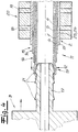
- FIGS. 2 to 8 It can be seen that according to a preferred embodiment and in the embodiment when establishing the connection between connector 3 and pipe 2, a mandrel 17 of the connector 3 in the interior of the pipe 2 can be inserted or inserted.
- the mandrel 17 on its outer side profiles - preferably and in the embodiment sawtooth-shaped profilings 21 - on.
- the first contact region 13 and the second contact region 15 are pressed or bent outward in particular under the action of the sawtooth-shaped profilings 21, so that the electrical contact between the contact regions 13, 15 and the electrical contact points 18, 19 of Connector 3 and the connecting sleeve 20 allows or facilitates.
- FIG. 5 Incidentally, it has been indicated by arrows on the connecting section 11 that the connecting section 11 and the mandrel 17 can be welded together, preferably by means of laser welding.
- the connector 3 has a cylindrical annular groove 22, in which annular groove 22 of the connecting portion 11 of the pipe 2 is inserted in establishing the connection between the connector 3 and pipe 2.
- annular groove 22 of the connecting portion 11 of the pipe 2 is inserted in establishing the connection between the connector 3 and pipe 2.
- the electrical contact points 18, 19 of the connector are arranged on the pipe side or connecting portion side inner surface of the annular groove 22 .
- the electrical contact pads 18, 19 of the connector 3 are connected to connector heating conductors, which may be formed as Verbinderschreibleiter Anlagenen 23, 24.
- Such connector heating conductor layers 23, 24, which preferably circulate over the entire circumference of the connector 3, are in the FIGS. 7 and 8th been hinted at.
- a stepped arrangement of the two heating segments 12, 14 or of the two contact regions 13, 15 of the connecting section 11 is realized.
- the inner surface of the annular groove 22 is conically formed in its front region, so that an effective electrical contact between the contact regions 13, 15 and the contact points 18, 19 can take place.
- This inner surface of the annular groove 22 could also - according to the formation of the connecting portion 11 - be designed step-shaped. In principle, the inner surface of the annular groove could also be formed only cylindrical.
- the connecting portion 11 with its contact areas 13, 15 between the mandrel 17 and the inner surface of the annular groove 22 as it were clamped, so that due to the clamping action a reliable electrical contact between the contact areas 13, 15 and the contact points 18, 19 results.
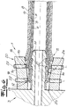
- FIGS. 4 to 8 show a connection of a connector 3 with a motor vehicle pipeline 2, including a connecting sleeve 20.
- a cylindrical connecting sleeve 20 is pushed onto the connecting section 11 of the pipeline 2 here.
- the connecting sleeve 20 surrounds the pipeline 2 and has a corresponding receiving channel 25 for the pipeline 2.
- the two electrical contact points 18, 19 are arranged, which when pushing or plugging the connection sleeve 20 are brought into electrical contact contact with the electrical contact areas 13, 15 of the connection section 11 or the pipeline 2.
- the mandrel 17 of the connector 3 is expediently inserted into the interior of the pipeline 2 or of the connecting section 11 (see in particular FIG. 5 ).
- the sawtooth-like profilings 21 of the mandrel 17 With the sawtooth-like profilings 21 of the mandrel 17, a pushing out or bending out of the electrical contact regions 13, 15 to the outside or in the direction of the contact points 18, 19 of the connecting sleeve 20 is achieved.
- the connecting portion 11 is clamped with its contact areas 13, 15 between the mandrel 17 and the connecting sleeve 20 as it were.
- the electrical contact points 18, 19 of the connecting sleeve 20 are connected to external electrical connections 27 of the connecting sleeve 20.
- the external electrical connections 27 are arranged on the outside of the connecting sleeve 20 facing away from the connecting section 11.
- the electrical contact points 18, 19 of the connection sleeve 20 are connected to the connector heating conductor layers 23, 24 extending through the connector 3 and heating the connector.
- the connector heater layers 23, 24 preferably extend at least over most of the length of the connector 3 and are recommended to run around the circumference of the connector Connector 3 um.
- the connector heating conductor layers 23, 24 may, like the heating conductor layers 5, 6 of the pipeline, consist of a conductive plastic. You could also consist of a metal foil or the like electrically conductive material.
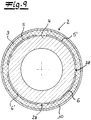
- the Fig. 9 shows another embodiment of a pipe according to the invention 2.
- four Bankleiter Anlagenen 5, 5 ', 6, 6' applied to the pipe 2 and an inner layer 4 of the pipe.
- This Bankleiter füren 5, 5 ', 6, 6' were printed by means of a printing process on the pipe 2 and on the inner layer 4.
- the Fig. 10 shows, the Schuleiter füren 5, 5 ', 6, 6' extend over the length of the pipe 2.
- the four Schuleiter füren 5, 5 ', 6, 6' are arranged as it were on a circumferential plane of the pipe 2 over the circumference of the pipe 2 side by side ( Fig. 9 ).
- An outer layer 8 is basically not required in this embodiment for the pipe 2.
- the Fig. 9 shows a thermal insulating layer 9 disposed on the heating conductor layers 5, 5 ', 6, 6'. Over the thermal insulating layer 9, an outer protective layer 10 is applied.
- Fig. 9 and 10 show that between the extending over the length of the pipe 2 Edelleiter Anlagenen 5, 5 ', 6, 6' gaps 28 are provided which separate these Bankleiter füren 5, 5 ', 6, 6' from each other or isolating from each other.
- a heat conductor layer 5, 5 ', 6, 6' over the length of the pipe 2 need not be formed continuously.
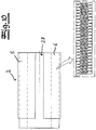
- FIGS. 11 and 12 show a connection sleeve 20 for the connection of a pipeline 2 according to the Fig. 9 and 10 to a connector 3 (connected state in FIG Fig. 13 ).
- the connecting sleeve has four sleeve heating conductor layers 29 for electrical contact with the heating conductor layers 5, 5 ', 6, 6' of the pipeline 2.
- the sleeve heating conductor layers 29 can in principle also be printed onto the connecting sleeve 20 by means of a printing method.
- the connector 3 has connector heating conductor layers 23, 24 printed on the connector 3 by a printing method. These connector heating conductor layers 23, 24 are brought into contact with the sleeve heating conductor layers 29 of the connecting sleeve 20 ( Fig. 13 ).
- the electrical contact between the contact areas 13, 15 of the pipe 2 and the contact points 18, 19 of the connector 3 and the connecting sleeve 20 only by pushing together or plugging together of the pipe 2 and connector 3 when establishing the connection between the pipe 2 and connector 3 or realized by connecting sleeve 20.
- the electrical connection between contact areas 13, 15 and contact points 18, 19 is preferably formed solder-free and / or crimp connection-free and / or screw connection and / or adhesive-free. Special and complex connection measures of the electrical contacts are basically not required within the scope of the invention.
Description
Die Erfindung betrifft ein Verbindungsaggregat aus einer beheizbaren Kraftfahrzeugleitung für die Durchleitung eines fluiden Mediums und einem beheizbaren Verbinder für die Verbindung mit der Kraftfahrzeugleitung. Es liegt im Rahmen der Erfindung, dass das durch die Kraftfahrzeugrohrleitung hindurchgeleitete fluide Medium erwärmt bzw. temperiert wird. Dabei handelt es sich vor allem um ein zu erwärmendes bzw. zu temperierendes flüssiges Medium. - Statt des Begriffes Kraftfahrzeugrohrleitung wird nachfolgend auch verkürzt der Begriff Rohrleitung verwendet. - Mit dem Verbinder kann die Rohrleitung an eine weitere Rohrleitung angeschlossen werden oder an eine andere Komponente, beispielsweise einen Tank für ein fluides Medium oder dergleichen. Als Verbinder wird nach besonders bevorzugter Ausführungsform der Erfindung ein Schnellverbinder (sogenannter Quick Connector) eingesetzt. Der erfindungsgemäße Verbinder bzw. Schnellverbinder ist nach besonders empfohlener Ausführungsform für eine lösbare Verbindung mit einer weiteren Komponente beziehungsweise mit einer weiteren Rohrleitung ausgelegt.The invention relates to a connection unit from a heatable motor vehicle line for the passage of a fluid medium and a heatable connector for connection to the motor vehicle line. It is within the scope of the invention that the fluid medium conducted through the motor vehicle pipeline is heated or tempered. This is above all a liquid medium to be heated or tempered. - Instead of the term motor vehicle pipeline is also shortened below the term pipeline used. - With the connector, the pipeline can be connected to another pipeline or to another component, such as a tank for a fluid medium or the like. As a connector according to a particularly preferred embodiment of the invention, a quick connector (so-called quick connector) is used. The connector or quick connector according to the invention is designed according to a particularly recommended embodiment for a detachable connection with another component or with a further pipeline.
Verbindungsaggregate der eingangs genannten Art sind aus der Praxis grundsätzlich in unterschiedlichen Ausführungsformen bekannt. So ist es bekannt, eine zu erwärmende bzw. zu temperierende wässrige Harnstofflösung im Rahmen eines SCR-Systems (SCR: Selective Catalytic Reduction) durch eine Kraftfahrzeugrohrleitung und auch durch einen daran angeschlossenen Verbinder zu leiten. In Kraftfahrzeugen, insbesondere in Kraftfahrzeugen mit Dieselmotor, ist in der Regel ein SCR-System mit einem SCR-Katalysator für die Abgasbehandlung vorhanden. Zwecks einer wirksamen Reduzierung der im Abgas eines Kraftfahrzeuges enthaltenen Stickoxide wird dem Abgas vor dem SCR-Katalysator eine Harnstofflösung zudosiert. Eine solche Harnstofflösung bzw. wässrige Harnstofflösung hat den Nachteil, dass Harnstoff bei Temperaturen unter-11 °C gefriert und teilweise auskristallisiert. Dadurch wird eine weitere funktionssichere Zufuhr der Harnstofflösung behindert oder sogar vollständig blockiert. Dann wird eine effektive Reduzierung der Stickoxide im Abgas beeinträchtigt bzw. verhindert. Zur Vermeidung solcher Störungen ist es bekannt die Kraftfahrzeugrohrleitungen für die Harnstofflösung zu beheizen. Die Beheizung der Kraftfahrzeugrohrleitung und eines daran angeschlossenen Verbinders erfolgt bei bekannten Systemen als elektrische Beheizung und zu diesem Zweck werden ein oder mehrere Heizdrähte an der Kraftfahrzeugleitung bzw. an dem Verbinder angeordnet. Viele bekannte Verbindungsaggregate haben den Nachteil, dass eine ausreichend effektive Temperierung bzw. Erwärmung des fluiden Mediums entweder nur unzureichend stattfindet oder nur mit aufwändigen bzw. kostenaufwändigen Maßnahmen möglich ist. Fernerhin sind die Verbindungen zwischen den Heizleitern der Kraftfahrzeugrohrleitung und den Heizleitern des Verbinders in der Regel aufwändig ausgeführt und außerdem störanfällig bzw. gegenüber mechanischen Beanspruchungen labil. Im Ergebnis sind die bekannten Verbindungsaggregate verbesserungsfähig.Connecting units of the type mentioned are basically known in practice in different embodiments. Thus, it is known to conduct an aqueous urea solution to be heated or tempered in the context of an SCR (SCR) system through a motor vehicle pipeline and also through a connector connected thereto. In motor vehicles, especially in motor vehicles with a diesel engine, an SCR system with an SCR catalytic converter for the exhaust gas treatment is usually present. For the purpose of effectively reducing the nitrogen oxides contained in the exhaust gas of a motor vehicle, a urea solution is metered into the exhaust gas upstream of the SCR catalytic converter. Such a urea solution or aqueous urea solution has the disadvantage that urea freezes at temperatures below -11 ° C and partially crystallized. As a result, a further functionally reliable supply of urea solution is hindered or even completely blocked. Then an effective reduction of nitrogen oxides in the exhaust gas is impaired or prevented. To avoid such disturbances, it is known to heat the motor vehicle piping for the urea solution. The heating of the motor vehicle pipeline and a connector connected thereto takes place in known systems as electrical heating and for this purpose one or more heating wires are arranged on the motor vehicle line or on the connector. Many known connection units have the disadvantage that a sufficiently effective temperature control or heating of the fluid medium either insufficiently takes place or is possible only with costly or costly measures. Furthermore, the connections between the heating conductors of the motor vehicle pipeline and the heating conductors of the connector are usually elaborate and also prone to failure or unstable to mechanical stresses. As a result, the known connection units can be improved.
Aus
Der Erfindung liegt das technische Problem zugrunde, ein Verbindungsaggregat der eingangs genannten Art anzugeben, bei dem die vorstehend geschilderten Nachteile funktionssicher vermieden werden können und das vor allem eine effektive Beheizung bei nichtsdestoweniger geringem Aufwand bzw. Kostenaufwand gewährleistet.The invention is based on the technical problem of specifying a connection unit of the type mentioned above, in which the above-described Disadvantages can be reliably avoided and above all ensures effective heating at nonetheless little effort or expense.
Zur Lösung dieses technischen Problems lehrt die Erfindung ein Verbindungsaggregat aus einer beheizbaren Kraftfahrzeugrohrleitung für die Durchleitung und Beheizung eines fluiden Mediums und einem beheizbaren Verbinder für die Verbindung bzw. für die unmittelbare Verbindung mit der Kraftfahrzeugrohrleitung, wobei die Rohrleitung zumindest einen flächigen Heizleiter aufweist, wobei sich der zumindest eine flächige Heizleiter über die Länge der Rohrleitung erstreckt bzw. sich im Wesentlichen über die Länge der Rohrleitung erstreckt und sich bis in einen Verbindungsabschnitt der Rohrleitung für die Verbindung mit dem Verbinder erstreckt,
wobei der zumindest eine flächige Heizleiter am Verbindungsabschnitt der Rohrleitung einen elektrischen Kontaktbereich aufweist und wobei beim Verbinden der Rohrleitung mit dem Verbinder bzw. beim Zusammenschieben und/oder Zusammenstecken von Rohrleitung und Verbinder der elektrische Kontaktbereich der Rohrleitung in elektrisch leitenden Berührungskontakt bzw. unmittelbar in elektrisch leitenden Berührungskontakt mit zumindest einer elektrischen Kontaktstelle des Verbinders oder einer im Zuge des Verbindens von Rohrleitung und Verbinder an bzw. auf dem Verbindungsabschnitt aufgebrachten Verbindungshülse kommt,
wobei beim Herstellen der Verbindung zwischen Verbinder und Rohrleitung ein Dorn des Verbinders in das Innere der Rohrleitung einschiebbar bzw. einsteckbar ist, wobei beim Einschieben bzw. beim Einstecken des Dorns der Kontaktbereich nach außen gedrückt bzw. gebogen wird, so dass der elektrische Berührungskontakt des Kontaktbereiches mit den elektrischenTo solve this technical problem, the invention teaches a connection unit of a heated motor vehicle pipeline for the passage and heating of a fluid medium and a heatable connector for the connection or for direct connection to the motor vehicle pipeline, wherein the pipeline has at least one planar heating conductor, wherein the at least one planar heating conductor extends over the length of the pipeline or extends essentially over the length of the pipeline and extends into a connection section of the pipeline for the connection to the connector,
wherein the at least one planar heating conductor has an electrical contact region at the connecting section of the pipeline, and wherein the electrical contact region of the pipeline is in electrically conductive contact contact or directly in electrically conductive when the pipeline is connected to the connector or when the pipeline and connector are pushed together and / or plugged together Comes into contact contact with at least one electrical contact point of the connector or a in the course of connecting the pipe and connector on or on the connecting portion applied connection sleeve
wherein when the connection between the connector and the pipeline, a mandrel of the connector in the interior of the pipeline is inserted or inserted, wherein when inserting or inserting the mandrel of the contact area is pressed or bent outwards, so that the electrical contact of the contact area with the electrical
Kontaktstellen des Verbinders bzw. der Verbindungshülse ermöglicht bzw. erleichtert wird und wobei der Dorn an seiner Außenseite sägezahnförmige Profilierungen aufweist, wobei die Profilierungen das Drücken bzw. Schieben des ersten und/oder des zweiten Kontaktbereiches nach außen unterstützen bzw. vereinfachen. - Wie weiter unten noch erläutert, weist die Rohrleitung nach besonders bevorzugter Ausführungsform zumindest zwei flächige Heizleiter auf.Contact points of the connector or the connecting sleeve is made possible or facilitated and wherein the mandrel has sawtooth-shaped profilings on its outer side, wherein the profilings support or simplify the pushing or pushing of the first and / or the second contact area to the outside. - As explained below, the pipe according to a particularly preferred embodiment, at least two flat heating element.
Es liegt im Rahmen der Erfindung, dass das fluide Medium durch die Kraftfahrzeugrohrleitung und durch den Verbinder hindurchgeleitet wird. Die erfindungsgemäße Kraftfahrzeugrohrleitung kann an ihren beiden Enden einen Verbindungsabschnitt bzw. einen angeschlossenen Verbinder aufweisen. Wie oben bereits dargelegt wird als Verbinder nach besonders bevorzugter Ausführungsform der Erfindung ein Schnellverbinder bzw. Quick Connector eingesetzt. Die an einen solchen Schnellverbinder bzw. Quick Connector angeschlossene weitere Rohrleitung oder das daran angeschlossene Aggregat kann auf einfache und zügige Weise von dem Schnellverbinder gelöst werden. - Empfohlenermaßen weist die Kraftfahrzeugleitung einen kreisförmigen Querschnitt bzw. einen im Wesentlichen kreisförmigen Querschnitt auf.It is within the scope of the invention that the fluid medium is passed through the motor vehicle pipeline and through the connector. The motor vehicle pipeline according to the invention may have a connecting section or a connected connector at its two ends. As already explained above, a quick connector or quick connector is used as connector according to a particularly preferred embodiment of the invention. The connected to such a quick connector or quick connector further pipeline or the unit connected thereto can be solved in a simple and timely manner of the quick connector. - Empfohlenermaßen, the motor vehicle line has a circular cross-section or a substantially circular cross-section.
Heizleiter meint im Rahmen der Erfindung einen elektrischen Leiter, der bei Durchleitung eines elektrischen Stromes zur Beheizung - im vorliegenden Fall des fluiden Mediums - genutzt werden kann. Flächiger Heizleiter meint im Rahmen der Erfindung einen Heizleiter, dessen Breite deutlich größer ist als die Dicke des Heizleiters. Vorzugsweise ist die Breite des Heizleiters zumindest dreimal, bevorzugt zumindest viermal und besonders bevorzugt zumindest fünfmal so groß wie die Dicke des Heizleiters.Heating conductor means in the context of the invention, an electrical conductor, which can be used in the passage of an electric current for heating - in the present case, the fluid medium. Flat heating element means in the context of the invention, a heating conductor whose width is significantly greater than the thickness of the heating element. Preferably, the width of the heat conductor is at least three times, preferably at least four times and more preferably at least five times as large as the thickness of the heating conductor.
Es liegt im Rahmen der Erfindung, dass eine Harnstofflösung bzw. eine wässrige Harnstofflösung für ein Katalysatorsystem des Kraftfahrzeuges als fluides Medium durch die Rohrleitung und zweckmäßigerweise auch durch den Verbinder geleitet wird. Der Einsatz einer Harnstofflösung bzw. wässrigen Harnstofflösung im Rahmen eines SCR-Systems eines Kraftfahrzeuges wurde bereits oben erläutert.It is within the scope of the invention that a urea solution or an aqueous urea solution for a catalyst system of the motor vehicle is passed as a fluid medium through the pipeline and expediently also through the connector. The use of a urea solution or aqueous urea solution in the context of an SCR system of a motor vehicle has already been explained above.
Es liegt weiterhin im Rahmen der Erfindung, dass die Rohrleitung eine Innenschicht aufweist, die in Kontakt mit dem durch die Rohrleitung geleiteten fluiden Medium steht. Die Innenschicht kann beispielsweise aus einem Fluorpolymer bestehen bzw. im Wesentlichen aus einem Fluorpolymer bestehen. Fernerhin kann die Innenoberfläche der Innenschicht leitfähig eingerichtet sein, insbesondere durch Leitfähigkeitszusätze in dem Kunststoff der Innenschicht. - Es liegt fernerhin im Rahmen der Erfindung, dass die Rohrleitung zumindest eine Außenschicht aufweist und dass der zumindest eine flächige Heizleiter zwischen der Innenschicht und der Außenschicht der Rohrleitung angeordnet ist. Die Außenschicht gewährleistet insbesondere einen Schutz bzw. einen mechanischen Schutz des zumindest einen Heizleiters. Zweckmäßigerweise ist die Kraftfahrzeugrohrleitung mit einer thermischen Isolierungsschicht ausgestattet, die bevorzugt an der Außenseite der Außenschicht der Rohrleitung angeordnet ist. Fernerhin kann die Kraftfahrzeugrohrleitung mit einer äußeren Schutzschicht versehen sein, die die Rohrleitung insbesondere vor äußeren mechanischen Beanspruchungen schützt. Gemäß einer Ausführungsform der Erfindung ist bei der Kraftfahrzeugrohrleitung von innen nach außen die folgende Schichtenfolge realisiert: Innenschicht - flächiger bzw. flächige Heizleiter - Außenschicht - thermische Isolierungsschicht - äußere Schutzschicht. Die thermische Isolierungsschicht kann entsprechend einer Ausführungsvariante als Luftschicht ausgebildet sein.It is furthermore within the scope of the invention that the pipeline has an inner layer which is in contact with the fluid medium conducted through the pipeline. The inner layer may for example consist of a fluoropolymer or consist essentially of a fluoropolymer. Furthermore, the inner surface of the inner layer may be arranged to be conductive, in particular by conductivity additives in the plastic of the inner layer. It is furthermore within the scope of the invention that the pipeline has at least one outer layer and that the at least one planar heating conductor is arranged between the inner layer and the outer layer of the pipeline. In particular, the outer layer ensures protection or mechanical protection of the at least one heating conductor. Conveniently, the motor vehicle pipeline is provided with a thermal insulation layer, which is preferably arranged on the outside of the outer layer of the pipeline. Furthermore, the motor vehicle pipeline can be provided with an outer protective layer, which protects the pipeline, in particular against external mechanical stresses. According to one embodiment of the invention, the following layer sequence is implemented in the motor vehicle pipeline from the inside to the outside: inner layer - planar or planar heating conductor - outer layer - thermal insulation layer - outer protective layer. The thermal insulation layer may be formed according to a variant embodiment as an air layer.
Nach besonders bevorzugter Ausführungsform, der im Rahmen ganz besondere Bedeutung zukommt, ist der zumindest eine flächige Heizleiter als Heizleiterschicht der Rohrleitung ausgebildet. Heizleiterschicht meint dabei insbesondere, dass die Schicht elektrisch leitfähig und die Rohrleitung beheizend ausgebildet ist. Die Ausbildung des zumindest einen flächigen Heizleiters als Schicht bzw. Heizleiterschicht, die das von dem fluiden Medium durchströmte Innere der Rohrleitung umgibt, hat sich im Rahmen der Erfindung besonders bewährt. Zweckmäßigerweise erstreckt sich eine Heizleiterschicht über die gesamte Länge der Rohrleitung bzw. im Wesentlichen über die gesamte Länge der Rohrleitung. Es liegt im Rahmen der Erfindung, dass eine Heizleiterschicht zumindest über einen Teil des Umfangs der Rohrleitung und nach einer Ausführungsform über den gesamten Umfang der Rohrleitung umläuft. Vorzugsweise läuft eine Heizleiterschicht über zumindest ein Achtel, bevorzugt über zumindest ein Siebtel und besonders bevorzugt über zumindest ein Sechstel des Umfangs der Rohrleitung um. Es liegt dabei im Rahmen der Erfindung, dass eine Heizleiterschicht parallel bzw. im Wesentlichen parallel zur Längsrichtung der Rohrleitung verläuft. Heizleiterschicht meint im Rahmen der Erfindung insbesondere, dass das die Heizleiterschicht bildende Material homogen bzw. im Wesentlichen homogen in der Heizleiterschicht verteilt ist. Insoweit unterscheidet sich eine erfindungsgemäße Heizleiterschicht beispielsweise von einem Aggregat aus einer Mehrzahl von Heizleiterdrähten oder dergleichen.According to a particularly preferred embodiment, which is of very particular significance in the context, the at least one planar heating conductor is designed as a heating conductor layer of the pipeline. Heizleiterschicht means in particular that the layer is electrically conductive and the pipe is formed heated. The formation of the at least one planar heat conductor as a layer or heat conductor layer which surrounds the interior of the pipeline through which the fluid medium flows has proven particularly useful in the context of the invention. Conveniently, a heat conductor layer extends over the entire length of the pipeline or substantially over the entire length of the pipeline. It is within the scope of the invention that a heat conductor layer rotates over at least part of the circumference of the pipeline and according to one embodiment over the entire circumference of the pipeline. Preferably, a heat conductor layer runs over at least one-eighth, preferably over at least one-seventh and more preferably over at least one-sixth of the circumference of the pipeline. It is within the scope of the invention that a heat conductor layer runs parallel or substantially parallel to the longitudinal direction of the pipeline. Heizleiterschicht means in the context of the invention, in particular, that the Heizleiterschicht forming material is homogeneously or substantially homogeneously distributed in the Heizleiterschicht. In that regard, a Heizleiterschicht invention differs for example from an aggregate of a plurality of Heizleiterdrähten or the like.
Eine besonders bevorzugte Ausführungsform der Erfindung ist dadurch gekennzeichnet, dass die Rohrleitung zumindest einen ersten flächigen Heizleiter und zumindest einen zweiten flächigen Heizleiter aufweist, wobei sich die beiden Heizleiter über die Länge der Rohrleitung erstrecken bzw. sich im Wesentlichen über die Länge der Rohrleitung erstrecken und sich bis in den Verbindungsabschnitt der Rohrleitung für die Verbindung mit dem Verbinder erstrecken, wobei die beiden Heizleiter am Verbindungsabschnitt der Rohrleitung jeweils einen elektrischen Kontaktbereich aufweisen und wobei beim Verbinden der Rohrleitung mit dem Verbinder bzw. beim Zusammenschieben und/oder Zusammenstecken von Rohrleitung und Verbinder die beiden elektrischen Kontaktbereiche der Rohrleitung in elektrisch leitenden Berührungskontakt mit zumindest zwei elektrischen Kontaktstellen des Verbinders oder einer im Zuge des Verbindens von Rohrleitung und Verbinder an bzw. auf dem Verbindungsabschnitt aufgebrachten Verbindungshülse kommen. Es liegt dabei im Rahmen der Erfindung, dass der zumindest eine erste flächige Heizleiter als Heizleiterschicht der Rohrleitung ausgebildet ist und/oder dass der zumindest eine zweite flächige Heizleiter als zweiter Heizleiterschicht der Rohrleitung ausgebildet ist.A particularly preferred embodiment of the invention is characterized in that the pipeline has at least one first planar heating conductor and at least one second planar heating conductor, wherein the two heating conductors extend over the length of the pipeline or extend substantially over the length of the pipeline and into the connecting section of the pipeline for connection to the connector extend, wherein the two heating conductors at the connecting portion of the pipeline each having an electrical contact area and wherein when connecting the pipe to the connector or when pushing together and / or mating of pipe and connector, the two electrical contact areas of the pipe in electrically conductive contact with at least two electrical Contact points of the connector or a in the course of connecting pipe and connector applied to or on the connecting portion connecting sleeve come. It is within the scope of the invention that the at least one first planar heating conductor is designed as a heating conductor layer of the pipeline and / or that the at least one second planar heating conductor is designed as a second heating conductor layer of the pipeline.
Gemäß einer Ausführungsform der Erfindung sind die Heizleiterschichten in Bezug auf die Schichtenfolge der Rohrleitung als innere Heizleiterschicht und als äußere Heizleiterschicht ausgebildet. Dabei umgibt die äußere Heizleiterschicht die innere Heizleiterschicht. Es wurde bereits oben dargelegt, dass nach bevorzugter Ausführungsform der Erfindung eine Innenschicht der Rohrleitung vorgesehen ist, die in Kontakt mit dem durch die Rohrleitung geleiteten fluiden Medium steht. Nach einer Ausführungsvariante der Erfindung ist die innere Heizleiterschicht der Innenschicht der Rohrleitung benachbart bzw. unmittelbar benachbart. Es wurde oben dargelegt, dass nach empfohlener Ausführungsform der Erfindung eine Außenschicht vorgesehen ist, die die Heizleiter und somit gemäß bevorzugter Ausführungsform die innere und die äußere Heizleiterschicht umgibt. Nach einer Ausführungsvariante schließt die Außenschicht an die äußere Heizleiterschicht bzw. unmittelbar an die äußere Heizleiterschicht an. - Es empfiehlt sich, dass zwischen der ersten Heizleiterschicht und der zweiten Heizleiterschicht zumindest eine Trennschicht bzw. eine zumindest elektrisch isolierende Trennschicht zwischengeschaltet ist. Auf diese Weise wird sichergestellt, dass keine elektrisch leitfähige Verbindung zwischen den beiden Heizleiterschichten vorliegt.According to one embodiment of the invention, the heat conductor layers are formed with respect to the layer sequence of the pipeline as an inner Heizleiterschicht and as an outer Heizleiterschicht. In this case, the outer Heizleiterschicht surrounds the inner Heizleiterschicht. It has already been stated above that according to a preferred embodiment of the invention an inner layer of the pipeline is provided which is in contact with the fluid medium conducted through the pipeline. According to one embodiment of the invention, the inner heating conductor layer of the inner layer of the pipeline adjacent or immediately adjacent. It has been stated above that according to the recommended embodiment of the invention, an outer layer is provided which surrounds the heating conductors and thus according to a preferred embodiment, the inner and outer Heizleiterschicht. According to one embodiment variant, the outer layer adjoins the outer heating conductor layer or directly to the outer heating conductor layer. It is recommended that at least one separating layer or an at least electrically insulating separating layer is interposed between the first heating conductor layer and the second heating conductor layer. This ensures that there is no electrically conductive connection between the two heating conductor layers.
Gemäß einer anderen bevorzugten Ausführungsform der Erfindung sind zumindest zwei Heizleiterschichten in der gleichen Umfangsebene der Rohrleitung angeordnet. Die zumindest zwei Heizleiterschichten sind dann also in Umfangsrichtung nebeneinander angeordnet und vorzugsweise nicht übereinander angeordnet. Diese Ausführungsform bietet sich insbesondere - aber nicht ausschließlich - an, wenn nach einer empfohlenen Ausführungsvariante die Heizleiterschichten mittels eines Druckverfahrens aufgebracht werden. Das wird weiter unten noch erläutert.According to another preferred embodiment of the invention, at least two Heizleiterschichten are arranged in the same circumferential plane of the pipeline. The at least two heat conductor layers are then arranged next to one another in the circumferential direction and are preferably not arranged one above the other. This embodiment is particularly - but not exclusively - if, according to a recommended embodiment, the heat conductor layers are applied by means of a printing process. This will be explained below.
Nach einer Ausführungsform der Erfindung besteht die zumindest eine Heizleiterschicht bzw. die erste und/oder die zweite Heizleiterschicht aus metallischem Material bzw. im Wesentlichen aus metallischem Material. Vorzugsweise ist dabei zumindest eine Heizleiterschicht bzw. sind zumindest zwei Heizleiterschichten als Metallfolie bzw. als Metallfilm ausgebildet. - Nach einer anderen Ausführungsform besteht zumindest eine Heizleiterschicht bzw. die erste Heizleiterschicht und/oder die zweite Heizleiterschicht aus zumindest einem leitfähigen Polymer bzw. aus zumindest einem leitfähigen Kunststoff. Es liegt im Rahmen der Erfindung, dass dem Polymer bzw. dem Kunststoff Leitfähigkeitszusätze zugefügt sind, so dass eine elektrische Leitfähigkeit bzw. eine Beheizungsfähigkeit des/der Heizleiter bzw. der Heizleiterschicht/Heizleiterschichten resultiert.According to one embodiment of the invention, the at least one heating conductor layer or the first and / or the second heating conductor layer consists of metallic material or essentially of metallic material. Preferably, at least one heating conductor layer or at least two heating conductor layers are formed as metal foil or as metal film. According to another embodiment, at least one heat conductor layer or the first heat conductor layer and / or the second heat conductor layer consists of at least one conductive polymer or of at least one conductive plastic. It is within the scope of the invention that conductivity additives are added to the polymer or the plastic so that an electrical conductivity or a heating capability of the heating conductor (s) or the heating conductor layer (s) results.
Gemäß einer bevorzugten Ausführungsform der Erfindung wird die zumindest eine Heizleiterschicht bzw. werden die Heizleiterschichten durch Aufdrucken mittels eines Druckverfahrens auf der Rohrleitung aufgebracht. Das Aufdrucken der Heizleiterschicht bzw. der Heizleiterschichten kann dabei beispielsweise mittels eines Tintenstrahldruckverfahrens und/oder mittels eines Siebdruckverfahrens erfolgen. Es liegt dabei im Rahmen der Erfindung, dass durch das Aufdruckverfahren eine Schichtdicke der Heizleiterschicht/der Heizleiterschichten realisiert wird, die die benötigte Heizleistung möglich macht, insbesondere eine Heizleistung von 10 bis 20 W/m. Bei den mittels des Druckverfahrens aufgebrachten Materialien kann es sich zum Beispiel um leitfähige Polymere handeln. Es können Pasten bzw. Dispersionen mit integrierten leitfähigen Partikeln verwendet werden. - Insbesondere beim Aufbringen von mehreren Heizleiterschichten mittels eines Druckverfahrens können die Schichten - wie oben bereits dargelegt - in einer Umfangsebene nebeneinander angeordnet sein. Es liegt dabei im Rahmen der Erfindung, dass zwischen den - zweckmäßigerweise sich in Längsrichtung der Rohrleitung erstreckenden - Heizleiterschichten bzw. Heizleiterschichtbahnen Zwischenräume angeordnet sind, so dass keine elektrisch leitfähige Verbindung zwischen den Heizleiterschichten vorliegt. Die Heizleiterschichten bzw. Heizleiterschichtbahnen sind zweckmäßigerweise im Endbereich des Verbindungsaggregates in Reihe oder in Serie geschaltet. Gemäß einer Ausführungsform sind die Heizleiterschichten/Heizleiterschichtbahnen bzw. die bevorzugt nebeneinander angeordneten Heizleiterschichten/Heizleiterschichtbahnen in Längsrichtung der Rohrleitung nicht vollflächig durchgehend realisiert. Insoweit können auch laterale Strukturen wie ein mäanderförmiger Verlauf von Heizleiterschichtabschnitten verwirklicht werden. Dabei sind die Heizleiterschichtabschnitte einer Heizleiterschicht in Längsrichtung der Rohrleitung leitend miteinander verbunden. Auf diese Weise können relativ einfach bestimmte Widerstandswerte bzw. Heizleistungen pro Längeneinheit der Rohrleitung eingestellt werden.According to a preferred embodiment of the invention, the at least one heat conductor layer or the heat conductor layers is applied by printing on the pipeline by means of a printing process. The printing of the Heizleiterschicht or Heizleiterschichten can, for example by means of an ink jet printing process and / or by means of a screen printing process. It is within the scope of the invention that a layer thickness of the Heizleiterschicht / Heizleiterschichten is realized by the printing process, which makes the required heating power possible, in particular a heating power of 10 to 20 W / m. The materials applied by means of the printing process may be, for example, conductive polymers. Pastes or dispersions with integrated conductive particles can be used. - In particular, when applying several Heizleiterschichten by means of a printing process, the layers - as already explained above - be arranged in a circumferential plane next to each other. It is within the scope of the invention that between the - advantageously in the longitudinal direction of the pipe extending - Heizleiterschichten or Heizleiterschichtbahnen interspaces are arranged so that there is no electrically conductive connection between the Heizleiterschichten. The Heizleiterschichten or Heizleiterschichtbahnen are suitably connected in the end region of the connection unit in series or in series. According to one embodiment, the heat conductor layers / heat conductor layer webs or the preferably adjacent heat conductor layers / heat conductor layer webs are not implemented in the longitudinal direction of the pipeline over the entire surface. In that regard, lateral structures such as a meandering course of Heizleiterschichtabschnitten can be realized. In this case, the Heizleiterschichtabschnitte a Heizleiterschicht in the longitudinal direction of the pipe are conductively connected together. In this way, it is relatively easy to set specific resistance values or heating powers per unit length of the pipeline.
Gemäß empfohlener Ausführungsform der Erfindung ist ein den ersten elektrischen Kontaktbereich bildendes bzw. aufweisendes erstes Heizsegment des ersten flächigen Heizleiters bzw. der ersten Heizleiterschicht in dem Verbindungsabschnitt der Rohrleitung an der Außenoberfläche der Rohrleitung bzw. des Verbindungsabschnittes angeordnet. Zweckmäßigerweise ist das erste Heizsegment bzw. der erste elektrische Kontaktbereich (vor dem Verbinden mit dem Verbinder bzw. mit der Verbindungshülse) nach außen hin frei und unbedeckt bzw. unbeschichtet ausgebildet. Weiterhin ist nach empfohlener Ausführungsform der Erfindung ein den zweiten elektrischen Kontaktbereich bildendes bzw. aufweisendes zweites Heizsegment des zweiten flächigen Heizleiters bzw. der zweiten Heizleiterschicht im Verbindungsabschnitt der Rohrleitung an der Außenoberfläche der Rohrleitung bzw. des Verbindungsabschnittes angeordnet. Es liegt auch hier im Rahmen der Erfindung, dass das zweite Heizsegment bzw. der zweite elektrische Kontaktbereich (vor dem Verbinden mit dem Verbinder bzw. mit der Verbindungshülse) nach außen hin frei und unbedeckt bzw. unbeschichtet ausgebildet ist. Diese freie und unbedeckte/unbeschichtete Ausführung der Heizsegmente bzw. der elektrischen Kontaktbereiche gewährleistet eine einfache Herstellung eines elektrischen Kontaktes beim Zusammenschieben bzw. Zusammenstecken der Rohrleitung und des Verbinders und optional der Verbindungshülse. Vorstehend wurde insbesondere eine Ausführungsform mit zwei flächigen Heizleitern bzw. mit zwei Heizleiterschichten erläutert. Die diesbezüglichen Ausführungen gelten aber auch für Rohrleitungen mit mehr als zwei flächigen Heizleitern bzw. Heizleiterschichten bzw. Heizleiterschichtbahnen. Das gilt ebenso für die nachfolgenden Ausführungen.In accordance with the recommended embodiment of the invention, a first heating segment of the first electrical contact area is or is provided The first planar heat conductor or the first Heizleiterschicht arranged in the connecting portion of the pipe to the outer surface of the pipe or the connecting portion. Expediently, the first heating segment or the first electrical contact region (prior to connection to the connector or to the connection sleeve) is designed to be free and uncovered or uncoated towards the outside. Furthermore, according to the recommended embodiment of the invention, a second heating segment forming the second electrical contact area of the second planar heating conductor or the second heating conductor layer is arranged in the connecting section of the pipeline on the outer surface of the pipeline or of the connecting section. It is also within the scope of the invention that the second heating segment or the second electrical contact region (before connecting to the connector or with the connecting sleeve) is designed to be free and uncovered or uncoated towards the outside. This free and uncovered / uncoated design of the heating segments or the electrical contact areas ensures easy production of an electrical contact when pushing together or plugging together the pipeline and the connector and optionally the connecting sleeve. In particular, an embodiment with two flat heat conductors or with two heat conductor layers has been explained above. However, the relevant explanations also apply to pipelines with more than two flat heating conductors or heat conductor layers or heat conductor layer webs. This also applies to the following remarks.
Gemäß einer Ausführungsvariante der Erfindung sind im Verbindungsabschnitt der Rohrleitung das erste Heizsegment des ersten flächigen Heizleiters bzw. der ersten Heizleiterschicht und das zweite Heizsegment des zweiten flächigen Heizleiters bzw. der zweiten Heizleiterschicht stufenförmig angeordnet. Die beiden Heizleiter bzw. Heizleiterschichten bilden im Verbindungsabschnitt somit eine Stufe. Diese Ausführungsvariante mit stufenförmigem Aufbau bezieht sich insbesondere auf die Ausgestaltung mit in radialer Richtung der Rohrleitung übereinander angeordneten flächigen Heizleitern bzw. Heizleiterschichten. Zweckmäßigerweise ist ein Aggregat aus erstem Heizleiter bzw. erster Heizleiterschicht, daran anschließender Trennschicht sowie aus zweitem Heizleiter bzw. zweiter Heizleiterschicht stufenförmig ausgeführt. Es liegt im Rahmen der Erfindung, dass der erste flächige Heizleiter bzw. die erste Heizleiterschicht sowie der zweite flächige Heizleiter bzw. die zweite Heizleiterschicht und bevorzugt auch die Trennschicht die Außenoberfläche des Verbindungsabschnittes der Rohrleitung bilden.According to an embodiment variant of the invention, the first heating segment of the first planar heating conductor or the first heating conductor layer and the second heating segment of the second planar heating conductor or the second heating conductor layer are arranged in steps in the connecting section of the pipeline. The two heating conductors or heating conductor layers thus form in the connecting section a step. This embodiment with a step-like structure relates in particular to the embodiment with planar heating conductors or heating conductor layers arranged one above the other in the radial direction of the pipeline. Conveniently, an aggregate of the first heating conductor or first heating conductor layer, subsequent separating layer and second heating conductor or second heating conductor layer is designed in steps. It is within the scope of the invention that the first planar heating conductor or the first heating conductor layer and the second planar heating conductor or the second heating conductor layer and preferably also the separating layer form the outer surface of the connecting portion of the pipeline.
Erfindungsgemäß wird beim Herstellen der Verbindung zwischen Verbinder und Rohrleitung ein Dorn des Verbinders in das Innere der Rohrleitung eingeschoben bzw. eingesteckt. Der Dorn greift an einem Ende der Rohrleitung in das Innere der Rohrleitung ein und bevorzugt in das Innere einer Innenschicht der Rohrleitung ein. Erfindungsgemäß wird beim Einschieben bzw. Einstecken des Dorns der Kontaktbereich/das Heizsegment bzw. werden die Kontaktbereiche/die Heizsegmente des Verbindungsabschnittes nach außen gedrückt bzw. nach außen gebogen. Auf diese Weise wird der elektrische Berührungskontakt des jeweiligen Heizsegmentes bzw. des jeweiligen Kontaktbereiches mit den elektrischen Kontaktstellen des Verbinders bzw. der Verbindungshülse ermöglicht bzw. erleichtert. Dadurch wird eine einfachere bzw. bessere elektrisch leitende Verbindung zwischen Kontaktbereichen und Kontaktstellen realisiert. Weiterhin ist die Erfindung dadurch gekennzeichnet, dass der Dorn an seiner Außenseite sägezahnförmige Profilierungen aufweist, wobei die Profilierungen das Drücken bzw. Biegen der Kontaktbereiche nach außen unterstützen.According to the invention, a mandrel of the connector is inserted or inserted into the interior of the pipeline when establishing the connection between the connector and the pipeline. The mandrel engages at one end of the tubing into the interior of the tubing and preferably into the interior of an inner layer of the tubing. According to the contact area / the heating segment or the contact areas / the heating segments of the connecting portion are pushed outwards or bent outwardly during insertion or insertion of the mandrel. In this way, the electrical contact with contact of the respective heating segment or the respective contact region with the electrical contact points of the connector or the connecting sleeve is made possible or facilitated. As a result, a simpler or better electrically conductive connection between contact areas and contact points is realized. Furthermore, the invention is characterized in that the mandrel has on its outside sawtooth-shaped profiles, wherein the profiling support the pressing or bending of the contact areas to the outside.
Eine empfohlene Ausführungsform des erfindungsgemäßen Verbindungsaggregates ist dadurch gekennzeichnet, dass der Verbinder eine Ringnut aufweist, in welche Ringnut die Rohrleitung bzw. der Verbindungsabschnitt der Rohrleitung beim Herstellen der Verbindung zwischen Verbinder und Rohrleitung einschiebbar ist. Zweckmäßigerweise sind an der rohrleitungsseitigen bzw. verbindungsabschnittseitigen Innenoberfläche der Ringnut die elektrischen Kontaktstellen des Verbinders angeordnet. Vorzugsweise ist die Rohrleitung bzw. ist der Verbindungsabschnitt der Rohrleitung bis zu einem Anschlagende der Ringnut in die Ringnut einschiebbar. Bei diesem Einschieben der Rohrleitung bzw. des Verbindungsabschnittes in die Ringnut des Verbinders findet vorzugsweise ohne weiteres bzw. mehr oder weniger automatisch der Berührungskontakt zwischen den Kontaktbereichen des Verbindungsabschnittes und den Kontaktstellen des Verbinders statt. Wenn die Heizleiter bzw. Heizleiterschichten des Verbindungsabschnittes stufenförmig angeordnet sind, kann auch eine abgestufte bzw. stufenförmige Anordnung der Kontaktstellen des Verbinders vorgesehen sein. Gemäß einer Ausführungsvariante ist die Ringnut bzw. die die elektrischen Kontaktstellen aufweisende Innenoberfläche der Ringnut zumindest bereichsweise konisch ausgebildet. Auch auf diese Weise kann funktionssicher ein elektrischer Berührungskontakt zwischen den Kontaktbereichen und den Kontaktstellen erreicht werden. Grundsätzlich kann auch die Außenoberfläche des Verbindungsabschnittes mit den Kontaktbereichen konisch ausgebildet sein. Es liegt im Übrigen im Rahmen der Erfindung, dass die Ringnut des Verbinders den in die Rohrleitung bzw. den in den Verbindungsabschnitt einzuschiebenden Dorn umgibt bzw. den größten Teil der Länge des Dorns umgibt.A recommended embodiment of the connection unit according to the invention is characterized in that the connector has an annular groove, in which annular groove, the pipe or the connecting portion of the pipe during insertion of the connection between the connector and the pipe is inserted. Conveniently, the electrical contact points of the connector are arranged on the pipe side or connecting portion side inner surface of the annular groove. Preferably, the pipe or the connecting portion of the pipe is inserted into the annular groove up to a stop end of the annular groove. In this insertion of the pipe or the connecting portion into the annular groove of the connector is preferably readily or more or less automatically the contact between the contact areas of the connecting portion and the contact points of the connector instead. If the heating conductors or heating conductor layers of the connecting portion are arranged in steps, a stepped arrangement of the contact points of the connector can also be provided. According to one embodiment, the annular groove or the internal contact surfaces of the inner surface of the annular groove is at least partially conical. In this way, reliable electrical contact between the contact areas and the contact points can be achieved. In principle, the outer surface of the connecting portion may be formed conically with the contact areas. It is, moreover, within the scope of the invention that the annular groove of the connector surrounds the mandrel to be inserted into the pipeline or the mandrel to be inserted into the connecting section or surrounds the greater part of the length of the mandrel.
Nach einer sehr bevorzugten Ausführungsform der Erfindung ist zur Herstellung eines elektrischen Berührungskontaktes eine Verbindungshülse im Zuge der Verbindung von Rohrleitung und Verbinder auf den Verbindungsabschnitt der Rohrleitung aufschiebbar bzw. aufsteckbar. Empfohlenermaßen sind an der verbindungsabschnittseitigen Innenseite der Verbindungshülse die elektrischen Kontaktstellen angeordnet, die beim Aufschieben bzw. Aufstecken mit den elektrischen Kontaktbereichen des Verbindungsabschnittes in elektrischen Berührungskontakt kommen bzw. gebracht werden. Nach einer Ausführungsvariante der Erfindung ist die Verbindungshülse entlang der Rohrleitung auf den Verbindungsabschnitt der Rohrleitung aufschiebbar. Zweckmäßigerweise umgibt bzw. umfasst die Verbindungshülse die Rohrleitung bzw. den Verbindungsabschnitt zumindest teilweise und bevorzugt vollständig. Es hat sich bewährt, dass die aufgeschobene Verbindungshülse an einer Anschlagfläche des Verbinders anliegt bzw. formschlüssig anliegt.According to a very preferred embodiment of the invention, a connecting sleeve is in the course of the connection of the pipeline and connector on the connecting portion of the invention for making an electrical contact Pipe pushed or attachable. Empfohlenermaßen the electrical connection points are arranged on the connection portion side inside of the connecting sleeve, which come when pushing or plugging with the electrical contact regions of the connecting portion in electrical contact with or are brought. According to one embodiment variant of the invention, the connecting sleeve can be pushed along the pipeline onto the connecting section of the pipeline. The connecting sleeve expediently surrounds or surrounds the pipeline or the connecting section at least partially and preferably completely. It has been proven that the deferred connection sleeve rests against a stop surface of the connector or rests positively.
Nach einer Ausführungsvariante ist die Verbindungshülse zylinderförmig bzw. im Wesentlichen zylinderförmig ausgebildet und bevorzugt ist der die Rohrleitung umgebende Aufnahmekanal der Verbindungshülse zylinderförmig bzw. im Wesentlichen zylinderförmig ausgebildet. Wenn die Heizsegmente der Heizleiter nach einer Ausführungsform stufenförmig ausgebildet sind, kann auch die Innenseite der Verbindungshülse stufenförmig oder konisch ausgeführt sein. - Es liegt im Rahmen der Erfindung, dass bei in die Rohrleitung eingeschobenem Dorn des Verbinders und bei auf den Verbindungsabschnitt aufgeschobener Verbindungshülse der Verbindungsabschnitt bzw. die Heizsegmente mit ihren Kontaktbereichen klemmend zwischen Verbindungshülse und Dorn aufgenommen wird/werden. Insoweit funktioniert die Verbindungshülse nach empfohlener Ausführungsform der Erfindung als Klemmhülse für den Verbindungsabschnitt bzw. für die elektrischen Kontaktbereiche des Verbindungsabschnittes. In dem auf den Verbindungsabschnitt aufgeschobenen Zustand der Verbindungshülse bzw. Klemmhülse kann die Form der Verbindungshülse aufgrund von Verformungen infolge der Klemmwirkung sich ändern bzw. von der Zylinderform abweichen. Das klemmende Aufschieben der Verbindungshülse gewährleistet einen funktionssicheren elektrischen Berührungskontakt zwischen den Kontaktbereichen des Verbindungsabschnittes und den Kontaktstellen der Verbindungshülse. - Nach einer Ausführungsform des erfindungsgemäßen Verbindungsaggregates sind die elektrischen Kontaktstellen der Verbindungshülse unmittelbar mit an der Verbindungshülse vorgesehenen elektrischen Außenanschlüssen verbunden, über die die elektrische Stromversorgung sichergestellt wird. Gemäß einer anderen nachfolgend erläuterten Ausführungsform sind die elektrischen Kontaktstellen der Verbindungshülse mit Heizleitern bzw. mit elektrischen Leitern des Verbinders verbunden. Nach einer Ausführungsvariante kann die elektrische Stromversorgung dann über diese Heizleiter bzw. elektrischen Leiter des Verbinders erfolgen. - Die Verbindungshülse kann in einer Ausgestaltung in Form einer zumindest bereichsweise elektrisch leitfähigen Klemme oder Klammer ausgebildet sein.According to one embodiment, the connecting sleeve is cylindrical or substantially cylindrical in shape, and preferably the receiving channel of the connecting sleeve surrounding the pipeline is cylindrical or substantially cylindrical. If the heating segments of the heating conductors are formed according to an embodiment step-shaped, also the inside of the connecting sleeve can be made step-shaped or conical. It is within the scope of the invention that, when the mandrel of the connector is pushed into the pipeline and the connecting sleeve is pushed onto the connecting section, the connecting section or heating segments are / are received with their contact areas in a clamping manner between the connecting sleeve and the mandrel. In that regard, the connection sleeve works according to the recommended embodiment of the invention as a clamping sleeve for the connecting portion and for the electrical contact areas of the connecting portion. In the pushed onto the connecting portion state of the connecting sleeve or clamping sleeve, the shape of the connecting sleeve due to deformation due to the clamping action change or deviate from the cylindrical shape. The jamming postponing the Connecting sleeve ensures a reliable electrical contact between the contact areas of the connecting portion and the contact points of the connecting sleeve. - According to one embodiment of the connecting unit according to the invention, the electrical contact points of the connecting sleeve are directly connected to provided on the connecting sleeve external electrical connections, via which the electrical power supply is ensured. According to another embodiment explained below, the electrical contact points of the connecting sleeve are connected to heating conductors or to electrical conductors of the connector. According to one embodiment variant, the electrical power supply can then take place via this heating conductor or electrical conductor of the connector. - The connection sleeve may be formed in an embodiment in the form of an at least partially electrically conductive terminal or clip.
Nach einer bevorzugten Ausführungsform, der im Rahmen des erfindungsgemäßen Verbindungsaggregates besondere Bedeutung zukommt, ist die zumindest eine elektrische Kontaktstelle bzw. sind die elektrischen Kontaktstellen des Verbinders und/oder der Verbindungshülse mit zumindest einem entlang des Verbinders verlaufenden und den Verbinder beheizenden Verbinderheizleiter verbunden. Empfohlenermaßen sind mehrere elektrische Kontaktstellen des Verbinders und/oder der Verbindungshülse mit entlang des Verbinders verlaufenden und den Verbinder beheizenden Verbinderheizleitern verbunden. Soweit nachfolgend von mehreren Verbinderheizleitern die Rede ist, beziehen sich die erläuterten Ausführungsformen auch auf die Ausführungsform mit nur einem den Verbinder beheizenden Verbindungsheizleiter. - Zweckmäßigerweise erstrecken sich die Verbinderheizleiter über zumindest den Großteil der Länge des Verbinders und bevorzugt über die gesamte Länge des Verbinders bzw. im Wesentlichen über die gesamte Länge des Verbinders. Es liegt im Rahmen der Erfindung, dass die Verbinderheizleiter als flächige Verbinderheizleiter ausgebildet sind. Eine besonders bevorzugte Ausführungsform zeichnet sich dadurch aus, dass die in dem Verbinder angeordneten und zur Beheizung des Verbinders vorgesehenen Verbinderheizleiter als Verbinderheizleiterschichten ausgebildet sind. Die Verbinderheizleiterschichten laufen empfohlenermaßen zumindest über einen Teil des Verbinderumfangs um und nach einer Ausführungsvariante über den gesamten Verbinderumfang um. Gemäß einer Ausführungsform bestehen die Verbinderheizleiterschichten aus Metall bzw. im Wesentlichen aus Metall und besonders bevorzugt sind die Verbinderheizleiterschichten als Metallfolie bzw. als Metallfilm ausgebildet. Nach einer anderen Ausführungsvariante der Erfindung bestehen die Verbinderheizleiterschichten aus einem leitfähigen Polymer bzw. leitfähigen Kunststoff oder im Wesentlichen aus einem leitfähigen Polymer bzw. leitfähigen Kunststoff. Dem Polymer/Kunststoff sind dabei zweckmäßigerweise Leitfähigkeitszusätze zugegeben. Es liegt im Rahmen der Erfindung, dass die Verbinderheizleiterschichten bezüglich der Materialwahl entsprechend den Heizleiterschichten der Kraftfahrzeugrohrleitung eingerichtet sind.According to a preferred embodiment, which is of particular importance in the context of the connecting unit according to the invention, the at least one electrical contact point or the electrical contact points of the connector and / or the connecting sleeve is connected to at least one connector heating conductor extending along the connector and heating the connector. It is recommended that a plurality of electrical contact points of the connector and / or the connecting sleeve are connected with connector heating conductors running along the connector and heating the connector. As far as the following is spoken of several Verbinderheizleitern, the illustrated embodiments also relate to the embodiment with only one connector heating connector heating conductor. Advantageously, the connector heating conductors extend over at least the major part of the length of the connector and preferably over the entire length of the connector or over substantially the entire length of the connector. It is within the scope of the invention that the Verbinderheizleiter are formed as a flat Verbinderheizleiter. A particularly preferred embodiment is characterized in that the Verbinderheizleiter arranged in the connector and provided for heating the connector are formed as Verbinderheizleiterschichten. The connector heating conductor layers are recommended to recirculate over at least part of the connector circumference and, in one embodiment, over the entire connector circumference. According to one embodiment, the connector heating conductor layers consist of metal or essentially of metal, and particularly preferably the connector heating conductor layers are formed as metal foil or as a metal film. According to another embodiment of the invention, the Verbinderheizleiterschichten consist of a conductive polymer or conductive plastic or substantially of a conductive polymer or conductive plastic. The polymer / plastic expediently added conductivity additives. It is within the scope of the invention that the Verbinderheizleiterschichten are arranged with respect to the choice of material according to the Heizleiterschichten the motor vehicle pipeline.
Eine empfohlene Ausführungsform der Erfindung ist dadurch gekennzeichnet, dass die Verbinderheizleiter bzw. die Verbinderheizleiterschichten durch Aufdrucken mittels eines Druckverfahrens auf den Verbinder aufgebracht sind. Auch bezüglich des Verbinders kann auf die zu der Rohrleitung im Zusammenhang mit dem Aufdrucken beschriebenen Ausführungsformen verwiesen werden. Die Verbinderheizleiter bzw. die Verbinderheizleiterschichten können mittels eines Druckverfahrens relativ einfach und wenig aufwendig aufgebracht werden. Auch hier können die Verbinderheizleiter bzw. Verbinderheizleiterschichten gleichsam in einer Umfangsebene des Verbinders und somit nebeneinander angeordnet werden. Das hat auch den Vorteil, dass Trennschichten bzw. Deckschichten auf dem Verbinderheizleiter bzw. auf den Verbinderheizleiterschichten grundsätzlich nicht erforderlich sind.A recommended embodiment of the invention is characterized in that the connector heating conductors and the connector heating conductor layers, respectively, are applied to the connector by printing by means of a printing process. With regard to the connector as well, reference may be made to the embodiments described for the pipeline in connection with the printing. The Verbinderheizleiter or the Verbinderheizleiterschichten can be applied relatively simply and inexpensively by means of a printing process. Again, the Verbinderheizleiter or Verbinderheizleiterschichten can be arranged as it were in a circumferential plane of the connector and thus adjacent to each other. This also has the advantage that Separating layers or cover layers on the Verbinderheizleiter or on the Verbinderheizleiterschichten are not required in principle.
Es liegt weiterhin im Rahmen der Erfindung, dass beim Herstellen der Verbindung zwischen Rohrleitung und Verbinder der elektrische Berührungskontakt zwischen den Kontaktbereichen der Rohrleitung und den Kontaktstellen des Verbinders/der Verbindungshülse lediglich durch Zusammenschieben bzw. Zusammenstecken von Rohrleitung und Verbinder und gegebenenfalls Verbindungshülse realisiert wird. Dabei liegt es insbesondere im Rahmen der Erfindung, dass der elektrische Berührungskontakt bzw. die elektrische Verbindung lötverbindungsfrei und/oder crimpverbindungsfrei und/oder klebverbindungsfrei und/oder schraubverbindungsfrei verwirklicht ist. Bevorzugt findet der elektrische Berührungskontakt also lediglich durch Zusammenschieben/Zusammenstecken der Komponenten und besonders bevorzugt mit Hilfe einer Klemmverbindung statt. Eine solche Klemmverbindung wird - wie oben bereits erläutert - insbesondere mittels der an der Außenseite des Dorns vorhandenen Profilierungen erreicht, wenn diese Profilierungen die Kontaktbereiche in Richtung der Kontaktstellen des Verbinders bzw. der Verbindungshülse drücken. Die Klemmwirkung bzw. Klemmverbindung kann nach einer Ausführungsform der Erfindung in der Ringnut des Verbinders realisiert werden. Nach einer anderen Ausführungsform wird - wie oben dargelegt - die Klemmwirkung bzw. Klemmverbindung mit der auf den Verbindungsabschnitt aufgeschobenen bzw. aufgesteckten Verbindungshülse verwirklicht.It is also within the scope of the invention that when establishing the connection between the pipe and connector, the electrical contact between the contact areas of the pipe and the contact points of the connector / the connecting sleeve is realized only by pushing or mating of pipe and connector and optionally connecting sleeve. It is in particular within the scope of the invention that the electrical contact or the electrical connection is realized solder-free and / or crimp connection free and / or adhesive-free and / or screw connection free. Preferably, the electrical contact thus takes place only by pushing together / plugging together of the components and particularly preferably by means of a clamping connection. As already explained above, such a clamping connection is achieved, in particular, by means of the profilings provided on the outside of the mandrel, when these profilings press the contact regions in the direction of the contact points of the connector or the connecting sleeve. The clamping action or clamping connection can be realized according to an embodiment of the invention in the annular groove of the connector. According to another embodiment - as stated above - the clamping action or clamping connection is realized with the pushed onto the connecting portion or plugging connection sleeve.
Der Erfindung liegt die Erkenntnis zugrunde, dass mit dem erfindungsgemäßen Verbindungsaggregat eine optimale Temperierung bzw. Beheizung sowohl der Kraftfahrzeugrohrleitung als auch eines an die Kraftfahrzeugrohrleitung angeschlossenen Verbinders realisiert werden kann. Der Erfindung liegt weiterhin die Erkenntnis zugrunde, dass dies insbesondere erreicht werden kann, wenn sowohl die Kraftfahrzeugrohrleitung als auch der Verbinder mit flächigen Heizleitern/Verbinderheizleitern bzw. mit Heizleiterschichten/Verbinderheizleiterschichten ausgestattet sind. Im Rahmen der Erfindung wird auf besonders einfache Weise eine elektrische Verbindung zwischen den Heizleitern der Kraftfahrzeugrohrleitung und den Verbinderheizleitern verwirklicht. Ein effektiver elektrischer Berührungskontakt wird dabei vor allem mit Hilfe der erfindungsgemäß bevorzugten Klemmverbindung in der Ringnut des Verbinders bzw. mittels der Verbindungshülse erzielt. Diese Verbindung ist sehr funktionssicher und kann ohne aufwendige Maßnahmen und insbesondere ohne spezielle bzw. aufwendige Verbindungsmaßnahmen erreicht werden. Zu betonen ist weiterhin, dass die elektrische Verbindung im Wesentlichen störanfälligkeitsfrei und resistent gegen mechanische Beeinträchtigungen ist. Hervorzuheben ist weiterhin, dass das erfindungsgemäße Verbindungsaggregat mit sehr einfachen und kostengünstigen Komponenten realisiert werden kann. Die Erfindung zeichnet sich zusammenfassend also vor allem durch geringen Aufwand und geringe Kosten aus.The invention is based on the finding that with the connection unit according to the invention an optimal temperature control or heating of both the motor vehicle pipeline and a connector connected to the motor vehicle pipeline can be realized. The invention is further based on the finding that this can be achieved in particular can, if both the motor vehicle pipeline and the connector with flat heating conductors / Verbinderheizleitern or with Heizleiterschichten / Verbinderheizleiterschichten are equipped. In the context of the invention, an electrical connection between the heating conductors of the motor vehicle pipeline and the Verbinderheizleitern is realized in a particularly simple manner. An effective electrical contact is achieved in particular by means of the invention preferred clamping connection in the annular groove of the connector or by means of the connecting sleeve. This compound is very reliable and can be achieved without expensive measures and in particular without special or complex connection measures. It should also be emphasized that the electrical connection is essentially susceptible to failure and resistant to mechanical damage. It should also be emphasized that the connection unit according to the invention can be realized with very simple and inexpensive components. The invention is characterized in summary so mainly by low cost and low cost.
Nachfolgend wird die Erfindung anhand einer lediglich ein Ausführungsbeispiel darstellenden Zeichnung näher erläutert. Es zeigen in schematischer Darstellung:
- Fig. 1
- Einen Schnitt durch eine Kraftfahrzeugrohrleitung eines erfindungsgemäßen Verbindungsaggregates,
- Fig. 2
- eine Seitenansicht des Gegenstandes gemäß
Fig. 1 , - Fig. 3
- eine Seitenansicht eines Verbindungsaggregates aus Verbinder und Rohrleitung,
- Fig. 4
- ein erfindungsgemäßes Verbindungsaggregat aus Verbinder, Rohrleitung und Verbindungshülse in einer ersten Funktionsstellung,
- Fig. 5
- den Gegenstand nach
Fig. 4 in einer zweiten Funktionsstellung, - Fig. 6
- den Gegenstand gemäß
Fig. 4 in einer dritten Funktionsstellung, - Fig. 7
- den Gegenstand nach
Fig. 6 in einer anderen Ausführungsform, - Fig. 8
- den Gegenstand gemäß
Fig. 6 in einer weiteren Ausführungsform, - Fig. 9
- einen Schnitt durch eine Kraftfahrzeugrohrleitung des erfindungsgemäßen Verbindungsaggregates in einer anderen Ausführungsform,
- Fig. 10
- eine Seitenansicht des Gegenstandes gemäß
Fig. 9 , - Fig. 11
- einen Schnitt durch eine weitere Ausführungsform einer Verbindungshülse,
- Fig. 12
- den Gegenstand nach
Fig. 11 in einer Seitenansicht, - Fig. 13
- ein erfindungsgemäßes Verbindungsaggregat aus Verbinder, Rohrleitung und Verbindungshülse (Rohrleitung gemäß
Fig. 9 ,10 und Verbindungshülse gemäßFig. 11, 12 ) und - Fig. 14
- einen Schnitt durch den Gegenstand nach
Fig. 13 .
- Fig. 1
- A section through a motor vehicle pipeline of a connecting unit according to the invention,
- Fig. 2
- a side view of the article according to
Fig. 1 . - Fig. 3
- a side view of a connection unit of connector and pipe,
- Fig. 4
- an inventive connecting assembly of connector, pipe and connecting sleeve in a first functional position,
- Fig. 5
- the object after
Fig. 4 in a second functional position, - Fig. 6
- the object according to
Fig. 4 in a third functional position, - Fig. 7
- the object after
Fig. 6 in another embodiment, - Fig. 8
- the object according to
Fig. 6 in a further embodiment, - Fig. 9
- a section through a motor vehicle pipeline of the connection unit according to the invention in another embodiment,
- Fig. 10
- a side view of the article according to
Fig. 9 . - Fig. 11
- a section through a further embodiment of a connecting sleeve,
- Fig. 12
- the object after
Fig. 11 in a side view, - Fig. 13
- an inventive connection unit of connector, pipe and connecting sleeve (pipe according to
Fig. 9 .10 and connecting sleeve according toFig. 11, 12th ) and - Fig. 14
- a section through the object after
Fig. 13 ,
Die Figuren zeigen ein Verbindungsaggregat 1 aus einer beheizbaren Kraftfahrzeugrohrleitung 2 für die Durchleitung eines fluiden Mediums und einem beheizbaren Verbinder 3 für die Verbindung mit der Kraftfahrzeugrohrleitung 2. Der Verbinder mag bevorzugt und im Ausführungsbeispiel als Schnellverbinder (Quick Connector) ausgebildet sein. Empfohlenermaßen wird eine wässrige Harnstofflösung für ein Katalysatorsystem eines Kraftfahrzeuges als fluides Medium durch die Rohrleitung 2 und durch den Verbinder 3 geleitet.The figures show a connection unit 1 from a heated
Insbesondere in der
In den
Erfindungsgemäß kommen beim Verbinden von Rohrleitung 2 und Verbinder 3 bzw. beim Zusammenschieben/Zusammenstecken von Rohrleitung 2 und Verbinder 3 die beiden elektrischen Kontaktbereiche 13, 15 der Rohrleitung 2 unmittelbar in elektrisch leitenden Berührungskontakt mit elektrischen Kontaktstellen bzw. mit zwei elektrischen Kontaktstellen 18 und 19 des Verbinders 3 oder einer Verbindungshülse 20. Bevorzugt und im Ausführungsbeispiel nach den Figuren erfolgt der elektrische Berührungskontakt zwischen den beiden Kontaktbereichen 13 und 15 der Rohrleitung 2 bzw. des Verbindungsabschnittes 11 und der beiden Kontaktstellen 18, 19 des Verbinders 3 bzw. der Verbindungshülse 20 allein durch Zusammenschieben bzw. Zusammenstecken der Komponenten. Eine Lötverbindung oder Crimpverbindung oder dergleichen zwischen den Kontaktbereichen 13, 15 und den elektrischen Kontaktstellen 18, 19 ist dabei grundsätzlich nicht notwendig.According to the invention, the two
In den
Im Ausführungsbeispiel nach
Die Ausführungsformen nach den
Im Ausführungsbeispiel nach
Die
Die
Die
Da gemäß bevorzugter Ausgestaltung bei dieser Ausführungsform keine Außenschicht 8 auf den Heizleiterschichten 5, 5', 6, 6' vorhanden ist (siehe insbesondere
Erfindungsgemäß wird beim Herstellen der Verbindung zwischen Rohrleitung 2 und Verbinder 3 der elektrische Berührungskontakt zwischen den Kontaktbereichen 13, 15 der Rohrleitung 2 und den Kontaktstellen 18, 19 des Verbinders 3 bzw. der Verbindungshülse 20 lediglich durch Zusammenschieben bzw. Zusammenstecken von Rohrleitung 2 und Verbinder 3 bzw. von Verbindungshülse 20 realisiert. Die elektrische Verbindung zwischen Kontaktbereichen 13, 15 und Kontaktstellen 18, 19 wird bevorzugt lötverbindungsfrei und/oder crimpverbindungsfrei und/oder schraubverbindungsfrei und/oder klebverbindungsfrei ausgebildet. Spezielle und aufwendige Verbindungsmaßnahmen der elektrischen Kontakte sind grundsätzlich im Rahmen der Erfindung nicht erforderlich.According to the invention, the electrical contact between the
Claims (19)
- A connection unit (1) comprising a heatable motor vehicle pipeline (2) for the passage of a fluid medium and a heatable connector (3) for the connection to the motor vehicle pipeline (2), wherein the pipeline (2) comprises at least one flat heating conductor, wherein the at least one heating conductor extends over the length of the pipeline (2) or extends substantially over the length of the pipeline (2) and extends into a connecting portion (11) of the pipeline (2) for the connection to the connector (3),
wherein the at least one flat heating conductor comprises an electrical contact region (13, 15) at the connecting portion (11) of the pipeline (2) and wherein, when the pipeline (2) is connected to the connector (3) or when pipeline (2) and connector (3) are pushed together and/or plugged together, the electrical contact region (13, 15) of the pipeline (2) comes into electrically conductive physical contact with an electrical contact point (18, 19) of the connector (3) or a connecting sleeve (20) applied to or on the connecting portion (11) during the connection of the pipeline (2) and the connector (3),
wherein, when the connection is produced between connector (3) and pipeline (2), a mandrel (17) of the connector (3) can be pushed or plugged into the interior of the pipeline (2),
wherein, when the mandrel (17) is pushed or plugged in, the contact region (13, 15) is pressed or curved outwards, so that the electrical physical contact of the contact region with the electrical contact points of the connector or of the connecting sleeve is enabled or facilitated
and wherein the mandrel (17) comprises sawtooth-shaped profiling (21) at its outer side, wherein the sawtooth-like profiling (21) assists or simplifies the pressing or pushing of the first and/or the second contact region (13, 15) outwards. - The connection unit according to claim 1, wherein the pipeline (2) comprises an inner layer (4), which is in contact with the fluid medium conveyed through the pipeline (2), wherein the pipeline (2) preferably comprises at least one outer layer (8) and wherein the at least one flat heating conductor is disposed between the inner layer (4) and the outer layer (8).
- The connection unit according to any one of claims 1 or 2, wherein the at least one flat heating conductor is constituted as a heat-conducting layer (5, 6) of the pipeline (2), wherein the heat-conducting layer (5, 6) runs around at least a part of the circumference of the pipeline (2) and, according to an embodiment, runs around the entire circumference of the pipeline (2).
- The connection unit according to any one of claims 1 or 3, wherein the pipeline (2) comprises at least one first flat heating conductor and at least one second flat heating conductor, wherein the two heating conductors extend over the length of the pipeline (2) or extend substantially over the length of the pipeline (2) and extend into the connecting portion (11) of the pipeline (2) for the connection to the connector (3), wherein the two heating conductors each comprise an electrical contact region (13, 15) at the connecting portion (11) of the pipeline (2) and wherein, when the pipeline (2) is connected to the connector (3) or when pipeline (2) and connector (3) are pushed together and/or plugged together, the two electrical contact regions (13, 15) of the pipeline (2) come into electrically conductive physical contact with at least two electrical contact points (18, 19) of the connector (3) or a connecting sleeve (20) applied to or on the connecting portion (11) during the connection of the pipeline (2) and the connector (3).
- The connection unit according to claim 4, wherein a separating layer (7) or an electrically insulating separating layer (7) is interposed between the first flat heating conductor or between the first heat-conducting layer (5) and the second flat heating conductor or the second heat-conducting layer (6).
- The connection unit according at any one of claims 3 to 5, wherein the at least one first and/or the at least one second heat-conducting layer (5, 6) is/are made of metallic material or essentially of metallic material and is/are preferably constituted as metal foil or as metal film.
- The connection unit according at any one of claims 3 to 6, wherein the at least one first heat-conducting layer (5) and/or the at least one second heat-conducting layer (6) is/are made of at least one conductive polymer or conductive plastic.
- The connection unit according at any one of claims 1 to 7, wherein at least one first heating segment (12) of the at least one first flat heating conductor or of the at least one first heat-conducting layer (5), said first heating segment forming or comprising the first electrical contact region (13), is disposed in the connecting portion (11) of the pipeline (2) at the outer surface of the pipeline (2) or of the connecting portion (11).
- The connection unit according at any one of claims 1 to 8, wherein at least one second heating segment (14) of the at least one second flat heating conductor or of the at least one second heat-conducting layer (6), said second heating segment forming or comprising the second electrical contact region (15), is disposed in the connecting portion (11) of the pipeline (2) at the outer surface of the pipeline (2) or of the connecting portion (11).
- The connection unit according at any one of claims 1 to 9, wherein the first heating segment (12) of the first flat heating conductor or of the first heat-conducting layer (5) and the second heating segment (14) of the second flat heating conductor or of the second heat-conducting layer (6) are disposed in a stepped manner in the connecting portion (11) of the pipeline (2).
- The connection unit according at any one of claims 1 to 10, wherein the first contact region (13) or the first heating segment (12) and the second contact region (15) or the second heating segment (14) is pressed or pushed outwards when the mandrel (17) is pushed or plugged in, so that the electrical physical contact with the electrical contact points (18, 19) of the connector (3) or of the connecting sleeve (20) is enabled or facilitated.
- The connection unit according at any one of claims 1 to 11, wherein the connector (3) comprises an annular groove (22), into which annular groove (22) the pipeline (2) or the connecting portion (11) of the pipeline (2) can be pushed when the connection between connector (3) and pipeline (2) is produced and wherein the at least one electrical contact point (18, 19) of the connector (3) or the electrical contact points (18, 19) of the connector (3) is/are disposed at the inner surface of the annular groove (22) on the pipeline side or the connecting portion side.
- The connection unit according at any one of claims 1 to 12, wherein a connecting sleeve (20) can be pushed or plugged onto the connecting portion (11) of the pipeline (2) to produce an electrical physical contact, wherein the at least one electrical contact point (18, 19) or the electrical contact points (18, 19) is/are disposed at the inner side (26) of the connecting sleeve (20) at the connecting portion side, said contact point or contact points coming into electrical physical contact with the at least one electrical contact region (13, 15) or with the electrical contact regions (13, 15) of the connecting portion (11) when the pushing-on or plugging-on takes place.
- The connection unit according at any one of claims 1 to 13, wherein the at least one electrical contact point (18, 19) or the electrical contact points (18, 19) of the connector (3) and/or of the connecting sleeve (20) is/are connected to at least one connector heating conductor running along the connector (3) and heating the connector (3), wherein the connector heating conductor or connector heating conductors preferably extends/extend over at least the major part of the length of the connector (3).
- The connection unit according at any one of claims 1 to 14, wherein at least one connector heating conductor disposed in the connector (3) and provided for heating the connector (3) is constituted as a connector heat- conducting layer (23, 24), which preferably runs around the major part of the connector circumference and, advisedly, around the entire connector circumference.
- The connection unit according at any one of claims 1 to 15, wherein, when the connection is produced between the pipeline (2) and the connector (3), the electrical physical contact between the contact region (13, 15) or the contact regions (13, 15) of the pipeline (2) and the contact point (18, 19) or the contact points (18, 19) of the connector (3) or of the connecting sleeve (20) is produced by the pushing together or plugging together of pipeline (2) and connector (3) and, if applicable, connecting sleeve (20).
- The connection unit according at any one of claims 1 to 16, wherein the at least one flat heating conductor or the flat heating conductors, in particular the at least one heat-conducting layer (5, 6) or the heat-conducting layers (5, 6), is/are applied by printing on the pipeline by means of a printing process.
- The connection unit according at any one of claims 14 to 17, wherein the at least one connector heating conductor or the connector heating conductors, in particular the at least one connector heat-conducting layer (23, 24) or the connector heat-conducting layers (23, 24), is/are applied by printing on the connector by means of a printing process.
- The connection unit according at any one of claims 1 to 18, wherein the connecting sleeve (20) is constituted in the form of a clamp or clip which is electrically conductive at least in sections.
Priority Applications (1)
| Application Number | Priority Date | Filing Date | Title |
|---|---|---|---|
| EP13194096.7A EP2876273B1 (en) | 2013-11-22 | 2013-11-22 | Connection unit for a heatable motor vehicle conduit and a heatable connector |
Applications Claiming Priority (1)
| Application Number | Priority Date | Filing Date | Title |
|---|---|---|---|
| EP13194096.7A EP2876273B1 (en) | 2013-11-22 | 2013-11-22 | Connection unit for a heatable motor vehicle conduit and a heatable connector |
Publications (2)
| Publication Number | Publication Date |
|---|---|
| EP2876273A1 EP2876273A1 (en) | 2015-05-27 |
| EP2876273B1 true EP2876273B1 (en) | 2017-01-04 |
Family
ID=49709468
Family Applications (1)
| Application Number | Title | Priority Date | Filing Date |
|---|---|---|---|
| EP13194096.7A Not-in-force EP2876273B1 (en) | 2013-11-22 | 2013-11-22 | Connection unit for a heatable motor vehicle conduit and a heatable connector |
Country Status (1)
| Country | Link |
|---|---|
| EP (1) | EP2876273B1 (en) |
Family Cites Families (4)
| Publication number | Priority date | Publication date | Assignee | Title |
|---|---|---|---|---|
| US5544275A (en) * | 1993-03-17 | 1996-08-06 | Applied Materials, Inc. | Electrically heated fluid carrying conduit having integrated heating elements and electrical conductors |
| DE102005048943A1 (en) * | 2005-10-13 | 2007-04-19 | Phoenix Fluid Handling Industry Gmbh | Heated hose |
| DE202009012230U1 (en) * | 2009-06-23 | 2010-11-04 | Voss Automotive Gmbh | Electrically heatable media cable and cable connectors |
| FR2958991B1 (en) * | 2010-04-14 | 2012-05-04 | Total Sa | DRIVE FOR TRANSPORTING A FLUID COMPRISING HYDROCARBON, AND METHOD OF MANUFACTURING SUCH A DRIVE. |
-
2013
- 2013-11-22 EP EP13194096.7A patent/EP2876273B1/en not_active Not-in-force
Also Published As
| Publication number | Publication date |
|---|---|
| EP2876273A1 (en) | 2015-05-27 |
Similar Documents
| Publication | Publication Date | Title |
|---|---|---|
| DE202010006739U1 (en) | Heater | |
| EP3372736B1 (en) | Connection unit | |
| EP3276243B1 (en) | Fluid line for motor vehicle | |
| EP2129885B1 (en) | Heatable pipeline | |
| EP3158250B1 (en) | Fluid line | |
| WO2011110408A2 (en) | Protecting water pipes from frost | |
| WO2014111246A1 (en) | Prefabricated heatable media line, use of such a media line, and method for producing same | |
| EP2652382B1 (en) | Heatable connection apparatus for media-conducting, electrically heatable hoses | |
| EP2801743B1 (en) | Method for connecting a conduit connector with a fluid-conducting motor vehicle line | |
| EP2496874B1 (en) | System for connecting hose lines | |
| EP1764541A1 (en) | Electric heating device, heatable hose and its manufacturing method | |
| EP1387440B1 (en) | Method for grounding a coated metallic pipe and a clip used for this method | |
| EP2876273B1 (en) | Connection unit for a heatable motor vehicle conduit and a heatable connector | |
| EP3477178B1 (en) | Heatable flexible hose with applied heating element | |
| EP2979018A1 (en) | Media line having a connector heating device | |
| DE202014003776U1 (en) | Plastic pipe | |
| DE202007007125U1 (en) | Heating means for heating a fluid | |
| DE102018208252A1 (en) | Method for producing a heating device and heating device produced therewith | |
| EP3587110A2 (en) | Metallic pipeline system with additively manufactured connecting part | |
| DE102020106220B3 (en) | Heating hose corrugated pipe connection | |
| EP2401892A1 (en) | Electric heater | |
| DE202015009640U1 (en) | welding connector | |
| EP2182268A1 (en) | Heating or cooling assembly for a pipe conduit | |
| EP3241666A1 (en) | Heating device | |
| EP1463153B1 (en) | Method for grounding a coated metallic pipe and coated metallic pipe |
Legal Events
| Date | Code | Title | Description |
|---|---|---|---|
| PUAI | Public reference made under article 153(3) epc to a published international application that has entered the european phase |
Free format text: ORIGINAL CODE: 0009012 |
|
| 17P | Request for examination filed |
Effective date: 20141124 |
|
| AK | Designated contracting states |
Kind code of ref document: A1 Designated state(s): AL AT BE BG CH CY CZ DE DK EE ES FI FR GB GR HR HU IE IS IT LI LT LU LV MC MK MT NL NO PL PT RO RS SE SI SK SM TR |
|
| AX | Request for extension of the european patent |
Extension state: BA ME |
|
| RBV | Designated contracting states (corrected) |
Designated state(s): AL AT BE BG CH CY CZ DE DK EE ES FI FR GB GR HR HU IE IS IT LI LT LU LV MC MK MT NL NO PL PT RO RS SE SI SK SM TR |
|
| 17Q | First examination report despatched |
Effective date: 20151124 |
|
| GRAP | Despatch of communication of intention to grant a patent |
Free format text: ORIGINAL CODE: EPIDOSNIGR1 |
|
| INTG | Intention to grant announced |
Effective date: 20160614 |
|
| GRAS | Grant fee paid |
Free format text: ORIGINAL CODE: EPIDOSNIGR3 |
|
| GRAA | (expected) grant |
Free format text: ORIGINAL CODE: 0009210 |
|
| AK | Designated contracting states |
Kind code of ref document: B1 Designated state(s): AL AT BE BG CH CY CZ DE DK EE ES FI FR GB GR HR HU IE IS IT LI LT LU LV MC MK MT NL NO PL PT RO RS SE SI SK SM TR |
|
| REG | Reference to a national code |
Ref country code: GB Ref legal event code: FG4D Free format text: NOT ENGLISH |
|
| REG | Reference to a national code |
Ref country code: CH Ref legal event code: EP |
|
| REG | Reference to a national code |
Ref country code: AT Ref legal event code: REF Ref document number: 859458 Country of ref document: AT Kind code of ref document: T Effective date: 20170115 |
|
| REG | Reference to a national code |
Ref country code: IE Ref legal event code: FG4D Free format text: LANGUAGE OF EP DOCUMENT: GERMAN |
|
| REG | Reference to a national code |
Ref country code: DE Ref legal event code: R096 Ref document number: 502013005964 Country of ref document: DE |
|
| REG | Reference to a national code |
Ref country code: LT Ref legal event code: MG4D Ref country code: NL Ref legal event code: MP Effective date: 20170104 |
|
| PG25 | Lapsed in a contracting state [announced via postgrant information from national office to epo] |
Ref country code: NL Free format text: LAPSE BECAUSE OF FAILURE TO SUBMIT A TRANSLATION OF THE DESCRIPTION OR TO PAY THE FEE WITHIN THE PRESCRIBED TIME-LIMIT Effective date: 20170104 |
|
| PG25 | Lapsed in a contracting state [announced via postgrant information from national office to epo] |
Ref country code: IS Free format text: LAPSE BECAUSE OF FAILURE TO SUBMIT A TRANSLATION OF THE DESCRIPTION OR TO PAY THE FEE WITHIN THE PRESCRIBED TIME-LIMIT Effective date: 20170504 Ref country code: FI Free format text: LAPSE BECAUSE OF FAILURE TO SUBMIT A TRANSLATION OF THE DESCRIPTION OR TO PAY THE FEE WITHIN THE PRESCRIBED TIME-LIMIT Effective date: 20170104 Ref country code: NO Free format text: LAPSE BECAUSE OF FAILURE TO SUBMIT A TRANSLATION OF THE DESCRIPTION OR TO PAY THE FEE WITHIN THE PRESCRIBED TIME-LIMIT Effective date: 20170404 Ref country code: HR Free format text: LAPSE BECAUSE OF FAILURE TO SUBMIT A TRANSLATION OF THE DESCRIPTION OR TO PAY THE FEE WITHIN THE PRESCRIBED TIME-LIMIT Effective date: 20170104 Ref country code: GR Free format text: LAPSE BECAUSE OF FAILURE TO SUBMIT A TRANSLATION OF THE DESCRIPTION OR TO PAY THE FEE WITHIN THE PRESCRIBED TIME-LIMIT Effective date: 20170405 Ref country code: LT Free format text: LAPSE BECAUSE OF FAILURE TO SUBMIT A TRANSLATION OF THE DESCRIPTION OR TO PAY THE FEE WITHIN THE PRESCRIBED TIME-LIMIT Effective date: 20170104 |
|
| PG25 | Lapsed in a contracting state [announced via postgrant information from national office to epo] |
Ref country code: PT Free format text: LAPSE BECAUSE OF FAILURE TO SUBMIT A TRANSLATION OF THE DESCRIPTION OR TO PAY THE FEE WITHIN THE PRESCRIBED TIME-LIMIT Effective date: 20170504 Ref country code: BG Free format text: LAPSE BECAUSE OF FAILURE TO SUBMIT A TRANSLATION OF THE DESCRIPTION OR TO PAY THE FEE WITHIN THE PRESCRIBED TIME-LIMIT Effective date: 20170404 Ref country code: SE Free format text: LAPSE BECAUSE OF FAILURE TO SUBMIT A TRANSLATION OF THE DESCRIPTION OR TO PAY THE FEE WITHIN THE PRESCRIBED TIME-LIMIT Effective date: 20170104 Ref country code: PL Free format text: LAPSE BECAUSE OF FAILURE TO SUBMIT A TRANSLATION OF THE DESCRIPTION OR TO PAY THE FEE WITHIN THE PRESCRIBED TIME-LIMIT Effective date: 20170104 Ref country code: ES Free format text: LAPSE BECAUSE OF FAILURE TO SUBMIT A TRANSLATION OF THE DESCRIPTION OR TO PAY THE FEE WITHIN THE PRESCRIBED TIME-LIMIT Effective date: 20170104 Ref country code: RS Free format text: LAPSE BECAUSE OF FAILURE TO SUBMIT A TRANSLATION OF THE DESCRIPTION OR TO PAY THE FEE WITHIN THE PRESCRIBED TIME-LIMIT Effective date: 20170104 Ref country code: LV Free format text: LAPSE BECAUSE OF FAILURE TO SUBMIT A TRANSLATION OF THE DESCRIPTION OR TO PAY THE FEE WITHIN THE PRESCRIBED TIME-LIMIT Effective date: 20170104 |
|
| REG | Reference to a national code |
Ref country code: DE Ref legal event code: R097 Ref document number: 502013005964 Country of ref document: DE |
|
| PG25 | Lapsed in a contracting state [announced via postgrant information from national office to epo] |
Ref country code: RO Free format text: LAPSE BECAUSE OF FAILURE TO SUBMIT A TRANSLATION OF THE DESCRIPTION OR TO PAY THE FEE WITHIN THE PRESCRIBED TIME-LIMIT Effective date: 20170104 Ref country code: SK Free format text: LAPSE BECAUSE OF FAILURE TO SUBMIT A TRANSLATION OF THE DESCRIPTION OR TO PAY THE FEE WITHIN THE PRESCRIBED TIME-LIMIT Effective date: 20170104 Ref country code: IT Free format text: LAPSE BECAUSE OF FAILURE TO SUBMIT A TRANSLATION OF THE DESCRIPTION OR TO PAY THE FEE WITHIN THE PRESCRIBED TIME-LIMIT Effective date: 20170104 Ref country code: EE Free format text: LAPSE BECAUSE OF FAILURE TO SUBMIT A TRANSLATION OF THE DESCRIPTION OR TO PAY THE FEE WITHIN THE PRESCRIBED TIME-LIMIT Effective date: 20170104 Ref country code: CZ Free format text: LAPSE BECAUSE OF FAILURE TO SUBMIT A TRANSLATION OF THE DESCRIPTION OR TO PAY THE FEE WITHIN THE PRESCRIBED TIME-LIMIT Effective date: 20170104 |
|
| PLBE | No opposition filed within time limit |
Free format text: ORIGINAL CODE: 0009261 |
|
| STAA | Information on the status of an ep patent application or granted ep patent |
Free format text: STATUS: NO OPPOSITION FILED WITHIN TIME LIMIT |
|
| REG | Reference to a national code |
Ref country code: FR Ref legal event code: PLFP Year of fee payment: 5 |
|
| PG25 | Lapsed in a contracting state [announced via postgrant information from national office to epo] |
Ref country code: DK Free format text: LAPSE BECAUSE OF FAILURE TO SUBMIT A TRANSLATION OF THE DESCRIPTION OR TO PAY THE FEE WITHIN THE PRESCRIBED TIME-LIMIT Effective date: 20170104 Ref country code: SM Free format text: LAPSE BECAUSE OF FAILURE TO SUBMIT A TRANSLATION OF THE DESCRIPTION OR TO PAY THE FEE WITHIN THE PRESCRIBED TIME-LIMIT Effective date: 20170104 |
|
| 26N | No opposition filed |
Effective date: 20171005 |
|
| PG25 | Lapsed in a contracting state [announced via postgrant information from national office to epo] |
Ref country code: SI Free format text: LAPSE BECAUSE OF FAILURE TO SUBMIT A TRANSLATION OF THE DESCRIPTION OR TO PAY THE FEE WITHIN THE PRESCRIBED TIME-LIMIT Effective date: 20170104 |
|
| PG25 | Lapsed in a contracting state [announced via postgrant information from national office to epo] |
Ref country code: MC Free format text: LAPSE BECAUSE OF FAILURE TO SUBMIT A TRANSLATION OF THE DESCRIPTION OR TO PAY THE FEE WITHIN THE PRESCRIBED TIME-LIMIT Effective date: 20170104 |
|
| GBPC | Gb: european patent ceased through non-payment of renewal fee |
Effective date: 20171122 |
|
| PG25 | Lapsed in a contracting state [announced via postgrant information from national office to epo] |
Ref country code: CH Free format text: LAPSE BECAUSE OF NON-PAYMENT OF DUE FEES Effective date: 20171130 Ref country code: LI Free format text: LAPSE BECAUSE OF NON-PAYMENT OF DUE FEES Effective date: 20171130 |
|
| PG25 | Lapsed in a contracting state [announced via postgrant information from national office to epo] |
Ref country code: LU Free format text: LAPSE BECAUSE OF NON-PAYMENT OF DUE FEES Effective date: 20171122 |
|
| REG | Reference to a national code |
Ref country code: BE Ref legal event code: MM Effective date: 20171130 |
|
| REG | Reference to a national code |
Ref country code: IE Ref legal event code: MM4A |
|
| PG25 | Lapsed in a contracting state [announced via postgrant information from national office to epo] |
Ref country code: MT Free format text: LAPSE BECAUSE OF FAILURE TO SUBMIT A TRANSLATION OF THE DESCRIPTION OR TO PAY THE FEE WITHIN THE PRESCRIBED TIME-LIMIT Effective date: 20170104 |
|
| PG25 | Lapsed in a contracting state [announced via postgrant information from national office to epo] |
Ref country code: IE Free format text: LAPSE BECAUSE OF NON-PAYMENT OF DUE FEES Effective date: 20171122 |
|
| PG25 | Lapsed in a contracting state [announced via postgrant information from national office to epo] |
Ref country code: GB Free format text: LAPSE BECAUSE OF NON-PAYMENT OF DUE FEES Effective date: 20171122 Ref country code: BE Free format text: LAPSE BECAUSE OF NON-PAYMENT OF DUE FEES Effective date: 20171130 |
|
| PG25 | Lapsed in a contracting state [announced via postgrant information from national office to epo] |
Ref country code: HU Free format text: LAPSE BECAUSE OF FAILURE TO SUBMIT A TRANSLATION OF THE DESCRIPTION OR TO PAY THE FEE WITHIN THE PRESCRIBED TIME-LIMIT; INVALID AB INITIO Effective date: 20131122 |
|
| PG25 | Lapsed in a contracting state [announced via postgrant information from national office to epo] |
Ref country code: CY Free format text: LAPSE BECAUSE OF FAILURE TO SUBMIT A TRANSLATION OF THE DESCRIPTION OR TO PAY THE FEE WITHIN THE PRESCRIBED TIME-LIMIT Effective date: 20170104 |
|
| PG25 | Lapsed in a contracting state [announced via postgrant information from national office to epo] |
Ref country code: MK Free format text: LAPSE BECAUSE OF FAILURE TO SUBMIT A TRANSLATION OF THE DESCRIPTION OR TO PAY THE FEE WITHIN THE PRESCRIBED TIME-LIMIT Effective date: 20170104 |
|
| REG | Reference to a national code |
Ref country code: AT Ref legal event code: MM01 Ref document number: 859458 Country of ref document: AT Kind code of ref document: T Effective date: 20181122 |
|
| PG25 | Lapsed in a contracting state [announced via postgrant information from national office to epo] |
Ref country code: AT Free format text: LAPSE BECAUSE OF NON-PAYMENT OF DUE FEES Effective date: 20181122 |
|
| PGFP | Annual fee paid to national office [announced via postgrant information from national office to epo] |
Ref country code: DE Payment date: 20191128 Year of fee payment: 7 |
|
| PGFP | Annual fee paid to national office [announced via postgrant information from national office to epo] |
Ref country code: FR Payment date: 20191128 Year of fee payment: 7 |
|
| PG25 | Lapsed in a contracting state [announced via postgrant information from national office to epo] |
Ref country code: TR Free format text: LAPSE BECAUSE OF FAILURE TO SUBMIT A TRANSLATION OF THE DESCRIPTION OR TO PAY THE FEE WITHIN THE PRESCRIBED TIME-LIMIT Effective date: 20170104 |
|
| PG25 | Lapsed in a contracting state [announced via postgrant information from national office to epo] |
Ref country code: AL Free format text: LAPSE BECAUSE OF FAILURE TO SUBMIT A TRANSLATION OF THE DESCRIPTION OR TO PAY THE FEE WITHIN THE PRESCRIBED TIME-LIMIT Effective date: 20170104 |
|
| REG | Reference to a national code |
Ref country code: DE Ref legal event code: R119 Ref document number: 502013005964 Country of ref document: DE |
|
| PG25 | Lapsed in a contracting state [announced via postgrant information from national office to epo] |
Ref country code: FR Free format text: LAPSE BECAUSE OF NON-PAYMENT OF DUE FEES Effective date: 20201130 |
|
| PG25 | Lapsed in a contracting state [announced via postgrant information from national office to epo] |
Ref country code: DE Free format text: LAPSE BECAUSE OF NON-PAYMENT OF DUE FEES Effective date: 20210601 |
|
| P01 | Opt-out of the competence of the unified patent court (upc) registered |
Effective date: 20230524 |