EP2876269A2 - Grätschsitzfahrzeug - Google Patents
Grätschsitzfahrzeug Download PDFInfo
- Publication number
- EP2876269A2 EP2876269A2 EP14174962.2A EP14174962A EP2876269A2 EP 2876269 A2 EP2876269 A2 EP 2876269A2 EP 14174962 A EP14174962 A EP 14174962A EP 2876269 A2 EP2876269 A2 EP 2876269A2
- Authority
- EP
- European Patent Office
- Prior art keywords
- vehicle
- component
- solenoid
- frame
- view
- Prior art date
- Legal status (The legal status is an assumption and is not a legal conclusion. Google has not performed a legal analysis and makes no representation as to the accuracy of the status listed.)
- Granted
Links
Images







Classifications
-
- F—MECHANICAL ENGINEERING; LIGHTING; HEATING; WEAPONS; BLASTING
- F01—MACHINES OR ENGINES IN GENERAL; ENGINE PLANTS IN GENERAL; STEAM ENGINES
- F01L—CYCLICALLY OPERATING VALVES FOR MACHINES OR ENGINES
- F01L13/00—Modifications of valve-gear to facilitate reversing, braking, starting, changing compression ratio, or other specific operations
- F01L13/0015—Modifications of valve-gear to facilitate reversing, braking, starting, changing compression ratio, or other specific operations for optimising engine performances by modifying valve lift according to various working parameters, e.g. rotational speed, load, torque
- F01L13/0036—Modifications of valve-gear to facilitate reversing, braking, starting, changing compression ratio, or other specific operations for optimising engine performances by modifying valve lift according to various working parameters, e.g. rotational speed, load, torque the valves being driven by two or more cams with different shape, size or timing or a single cam profiled in axial and radial direction
-
- B—PERFORMING OPERATIONS; TRANSPORTING
- B62—LAND VEHICLES FOR TRAVELLING OTHERWISE THAN ON RAILS
- B62K—CYCLES; CYCLE FRAMES; CYCLE STEERING DEVICES; RIDER-OPERATED TERMINAL CONTROLS SPECIALLY ADAPTED FOR CYCLES; CYCLE AXLE SUSPENSIONS; CYCLE SIDECARS, FORECARS, OR THE LIKE
- B62K11/00—Motorcycles, engine-assisted cycles or motor scooters with one or two wheels
- B62K11/02—Frames
- B62K11/04—Frames characterised by the engine being between front and rear wheels
-
- F—MECHANICAL ENGINEERING; LIGHTING; HEATING; WEAPONS; BLASTING
- F01—MACHINES OR ENGINES IN GENERAL; ENGINE PLANTS IN GENERAL; STEAM ENGINES
- F01L—CYCLICALLY OPERATING VALVES FOR MACHINES OR ENGINES
- F01L1/00—Valve-gear or valve arrangements, e.g. lift-valve gear
- F01L1/26—Valve-gear or valve arrangements, e.g. lift-valve gear characterised by the provision of two or more valves operated simultaneously by same transmitting-gear; peculiar to machines or engines with more than two lift-valves per cylinder
- F01L1/267—Valve-gear or valve arrangements, e.g. lift-valve gear characterised by the provision of two or more valves operated simultaneously by same transmitting-gear; peculiar to machines or engines with more than two lift-valves per cylinder with means for varying the timing or the lift of the valves
-
- F—MECHANICAL ENGINEERING; LIGHTING; HEATING; WEAPONS; BLASTING
- F02—COMBUSTION ENGINES; HOT-GAS OR COMBUSTION-PRODUCT ENGINE PLANTS
- F02B—INTERNAL-COMBUSTION PISTON ENGINES; COMBUSTION ENGINES IN GENERAL
- F02B61/00—Adaptations of engines for driving vehicles or for driving propellers; Combinations of engines with gearing
- F02B61/02—Adaptations of engines for driving vehicles or for driving propellers; Combinations of engines with gearing for driving cycles
-
- F—MECHANICAL ENGINEERING; LIGHTING; HEATING; WEAPONS; BLASTING
- F01—MACHINES OR ENGINES IN GENERAL; ENGINE PLANTS IN GENERAL; STEAM ENGINES
- F01L—CYCLICALLY OPERATING VALVES FOR MACHINES OR ENGINES
- F01L1/00—Valve-gear or valve arrangements, e.g. lift-valve gear
- F01L1/12—Transmitting gear between valve drive and valve
- F01L1/18—Rocking arms or levers
- F01L1/181—Centre pivot rocking arms
-
- F—MECHANICAL ENGINEERING; LIGHTING; HEATING; WEAPONS; BLASTING
- F01—MACHINES OR ENGINES IN GENERAL; ENGINE PLANTS IN GENERAL; STEAM ENGINES
- F01L—CYCLICALLY OPERATING VALVES FOR MACHINES OR ENGINES
- F01L1/00—Valve-gear or valve arrangements, e.g. lift-valve gear
- F01L1/02—Valve drive
- F01L1/04—Valve drive by means of cams, camshafts, cam discs, eccentrics or the like
- F01L1/047—Camshafts
- F01L1/053—Camshafts overhead type
- F01L2001/0535—Single overhead camshafts [SOHC]
-
- F—MECHANICAL ENGINEERING; LIGHTING; HEATING; WEAPONS; BLASTING
- F01—MACHINES OR ENGINES IN GENERAL; ENGINE PLANTS IN GENERAL; STEAM ENGINES
- F01L—CYCLICALLY OPERATING VALVES FOR MACHINES OR ENGINES
- F01L2305/00—Valve arrangements comprising rollers
-
- F—MECHANICAL ENGINEERING; LIGHTING; HEATING; WEAPONS; BLASTING
- F01—MACHINES OR ENGINES IN GENERAL; ENGINE PLANTS IN GENERAL; STEAM ENGINES
- F01L—CYCLICALLY OPERATING VALVES FOR MACHINES OR ENGINES
- F01L2820/00—Details on specific features characterising valve gear arrangements
- F01L2820/03—Auxiliary actuators
- F01L2820/031—Electromagnets
Definitions
- the present invention relates to a straddle-type vehicle, and more precisely relates to a straddle-type vehicle comprising a variable valve mechanism.
- straddle-type vehicle An example of a straddle-type vehicle is a scooter-type motorcycle.
- scooters equipped with variable valve mechanisms have been proposals for scooters equipped with variable valve mechanisms in recent years.
- JP 2009-185639 A discloses a scooter-type motorcycle.
- This scooter has an engine equipped with a variable valve apparatus.
- the variable valve apparatus comprises an exhaust valve cam, a separate cam, a camshaft, and a solenoid.
- the separate cam is provided separately from the exhaust valve cam.
- the solenoid moves the separate cam in the axial direction of the camshaft.
- JP 2010-236384 A also discloses a scooter-type motorcycle.
- This scooter has an engine equipped with a variable valve mechanism.
- the variable valve mechanism comprises an exhaust cam, a separate cam, a camshaft, and a solenoid.
- the separate cam is provided separately from the exhaust cam.
- the solenoid slides the separate cam along the camshaft.
- the solenoid is disposed to the side of the cylinder, and the output shaft (actuator rod) of the solenoid moves parallel to the cylinder axis. Accordingly, less space is needed for the solenoid in the left and right direction of the vehicle. That is, the solenoid can be disposed closer to the cylinder.
- the separate cam operated by the solenoid moves in a direction that intersects the cylinder axis (more specifically, the left and right direction of the vehicle). Therefore, the drive force of the solenoid must be transmitted through a link mechanism to the separate cam. This requires the solenoid to have a higher drive force, and this means that the solenoid ends up being larger (and particularly in the left and right direction of the vehicle).
- the engine is disposed so as to be capable of pivoting with respect to the body frame.
- the engine is disposed under the seat. Therefore, when a larger solenoid is installed to the side of the engine, the dimensions in the left and right direction of the vehicle increase at the portion around the seat in the front-to-rear direction of the vehicle. More specifically, the dimensions in the left and right direction of the vehicle increase at the portion located under the seat in a side view of the vehicle.
- JP 2009-185639 A the solenoid is exposed in a side view of the vehicle.
- stones and so forth kicked up by the movement of the vehicle can strike the solenoid, or dirty water splashed up by the movement of the vehicle can adhere to the solenoid.
- JP 2010-236384 A the solenoid is hidden by a duct in a side view of the vehicle. That is, the duct is located outside the solenoid in the left and right direction of the vehicle. Accordingly, the dimensions in the left and right direction of the vehicle increase at the portion around the seat in the front-to-rear direction of the vehicle. More specifically, the dimensions in the left and right direction of the vehicle increase at the portion located under the seat in a side view of the vehicle.
- a scooter comprises a foot rest component on which the rider places his feet while riding the vehicle.
- the foot rest component is located in front of and under the seat. Accordingly, rider comfort (specifically, ease of operation when getting on the vehicle, and a comfortable riding posture) is better with a scooter.
- rider comfort specifically, ease of operation when getting on the vehicle, and a comfortable riding posture
- the dimensions in the left and right direction of the vehicle increase at the portion around the seat of a scooter (more specifically, the portion located under the seat)
- this can make the vehicle less comfortable.
- the rider is located at the portion around the seat in the front-to-rear direction of the vehicle. That is, this increased size can get in the rider's way in moving the vehicle around or in operating it when getting on it.
- the straddle-type vehicle pertaining to an embodiment of the present invention comprises a body frame, a body cover, a seat, and an engine unit.
- the body cover covers the body frame.
- the seat is supported by the body frame.
- the engine unit is disposed so as to be capable of pivoting with respect to the body frame, and is located under the seat.
- the body frame includes a left frame component and a right frame component.
- the left frame component extends in the front-to-rear direction of the vehicle.
- the right frame component extends in the front-to-rear direction of the vehicle and is located to the right of the left frame component in the left and right direction of the vehicle.
- the left frame component and the right frame component include a lower frame component and an inclined frame component.
- the lower frame component extends in the front-to-rear direction, ahead of the engine unit.
- the inclined frame component extends rearward and upward from the rear end of the lower frame component.
- the body cover includes a foot rest component.
- the foot rest component is located lower than the seat and at least part of the foot rest component is superposed with the lower frame component in a plan view of the vehicle.
- the engine unit comprises a cylinder, a valve, and a variable valve mechanism.
- the valve opens and closes an intake passage or exhaust passage formed in the cylinder.
- the variable valve mechanism switches the amount of displacement of the valve.
- the variable valve mechanism includes a solenoid.
- the solenoid has an output shaft.
- the solenoid is disposed between the cylinder and either the left frame component or the right frame component in a plan view of the vehicle.
- the output shaft is capable of moving in a reciprocating manner in the left and right direction of the vehicle.
- the solenoid is superposed with the inclined frame component of one of the frame components in
- the solenoid can be protected while rider comfort is maintained.
- a variable valve mechanism includes a solenoid.
- the drive force of the solenoid is used to switch members for driving valves.
- the engine is disposed so as to be capable of pivoting with respect to the body frame.
- the engine is disposed under the seat.
- a foot rest component is disposed in front of the engine unit. Therefore, with a scooter, space for installing members is limited around the front of the engine unit, and the solenoid has to be installed in this limited space.
- One possible way to install a solenoid is to make the output shaft of the solenoid parallel to the cylinder axis.
- the size of the engine unit, including the solenoid, in the left and right direction of the vehicle can be more compact than when the output shaft of the solenoid is parallel in the left and right direction of the vehicle. Therefore, the dimensions in the left and right direction of the vehicle can be reduced at the portion around the seat in the front-to-rear direction of the vehicle. More specifically, the dimensions in the left and right direction of the vehicle can be reduced at the portion located under the seat.
- the cylinder axis extends in the front-to-rear direction of the vehicle.
- members to which the drive force of the solenoid is transmitted are disposed so that they can move in the left and right direction of the vehicle. Therefore, the drive force of the solenoid must be transmitted to the above-mentioned members via a link mechanism.
- the solenoid becomes larger in the left and right direction of the vehicle in particular.
- the engine is disposed so that it is able to pivot with respect to the body frame. Also, the engine is located under the seat. Therefore, if a larger solenoid is installed to the side of the engine, the dimensions in the left and right direction of the vehicle will be larger at the portion around the seat in the front-to-rear direction of the vehicle. More specifically, the dimensions in the left and right direction of the vehicle will be larger at the portion located under the seat. Also, the link mechanism is located to the side of the engine unit. Therefore, because the link mechanism is installed, the dimensions in the left and right direction of the vehicle become larger at the portion around the seat in the front-to-rear direction of the vehicle. More specifically, the dimensions in the left and right direction of the vehicle become larger at the portion located under the seat.
- a scooter comprises a foot rest component.
- the foot rest component is located in front of and under the seat. Accordingly, rider comfort is better with a scooter. More specifically, operation when getting on the vehicle is easier, and the riding posture is more comfortable.
- the solenoid should be disposed so that the dimensions in the left and right direction of the vehicle are smaller.
- stones and so forth kicked up by the movement of the vehicle can strike the solenoid, or dirty water splashed up by the movement of the vehicle can adhere to the solenoid. The probability that such a problem will be encountered rises as the solenoid becomes larger.
- the inventors discovered a structure in which the output shaft of the solenoid is disposed so that it can move in the left and right direction of the vehicle, and the solenoid is disposed at a location that is protected by the body frame, while avoiding an increase in the size of the solenoid.
- straddle-type vehicle pertaining to an embodiment of the present invention will now be described through reference to the drawings.
- a scooter type of motorcycle will be described as an example of a straddle-type vehicle.
- Portions in the drawings that are the same or equivalent will be numbered the same, and these members will not be described more than once.
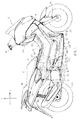
- FIG. 1 is a right side view of a motorcycle 10 pertaining to an embodiment of the present invention.
- the terms front, rear, left, and right refer to those directions as seen by a rider seated on a seat 21 of the motorcycle 10.
- the arrow F indicates the front direction of the motorcycle 10
- the arrow U refers to the up direction of the motorcycle 10.
- the motorcycle 10 comprises a front wheel 12F, a rear wheel 12R, a body frame 14, a body cover 20, the seat 21, an engine unit 22, and a fuel tank 24.
- the body frame 14 comprises a head pipe 14A, a front frame 14B, a left frame 14C, and a right frame 14D.
- the head pipe 14A is disposed at the front part of the body frame 14.
- a steering shaft is inserted into the head pipe 14A.
- a handlebar 26 (see FIG. 1 ) is disposed at the upper end of the steering shaft.
- a front fork 28 (see FIG. 1 ) is disposed at the lower end of the steering shaft.
- the front fork 28 rotatably supports the front wheel 12F. As the handlebar 26 is turned, the front wheel 12F also turns in a plan view of the vehicle.
- the front frame 14B is connected to the head pipe 14A.
- the front frame 14B extends downward from the head pipe 14A.
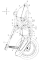
- the left frame 14C will now be described through reference to FIG. 2 .
- the left frame 14C extends in the front-to-rear direction of the vehicle.
- the left frame 14C includes an upper-left frame 16A, a lower-left frame 16B, and a left reinforcing frame 16C.
- the upper-left frame 16A is connected to the front frame 14B.
- the upper-left frame 16A extends rearward from the front frame 14B.
- the lower-left frame 16B is connected to the front frame 14B.
- the lower-left frame 16B extends rearward from the front frame 14B.
- the rear end of the lower-left frame 16B is connected to the upper-left frame 16A.
- the lower-left frame 16B includes a front part 30A, a middle part 30B, an inclined part 30C, and a rear part 30D.
- the front part 30A is connected to the front frame 14B.
- the front part 30A extends downward from the front frame 14B.
- the middle part 30B extends rearward from the lower end of the front part 30A.
- the middle part 30B extends in the front-to-rear direction of the vehicle, ahead of the engine unit 22.
- the inclined part 30C extends rearward and diagonally upward from the rear end of the middle part 30B.
- the rear part 30D extends rearward from the rear end of the inclined part 30C.
- the rear part of the rear part 30D is connected to the upper-left frame 16A.
- the left reinforcing frame 16C is connected to the upper-left frame 16A and the lower-left frame 16B.
- the right frame 14D will be described through reference to FIG. 3 .
- the right frame 14D extends in the front-to-rear direction of the vehicle.
- the right frame 14D includes an upper-right frame 18A, a lower-right frame 18B, and a right reinforcing frame 18C.
- the upper-right frame 18A is connected to the front frame 14B.
- the upper-right frame 18A extends rearward from the front frame 14B.
- the lower-right frame 18B is connected to the front frame 14B.
- the lower-right frame 18B extends rearward from the front frame 14B.
- the rear end of the lower-right frame 18B is connected to the upper-right frame 18A.
- the lower-right frame 18B includes a front part 32A, a middle part 32B, an inclined part 32C, and a rear part 32D.
- the front part 32A is connected to the front frame 14B.
- the front part 32A extends downward from the front frame 14B.
- the middle part 32B extends rearward from the lower end of the front part 32A. As shown in FIG. 4 , the middle part 32B extends in the front-to-rear direction of the vehicle, ahead of the engine unit 22.
- the inclined part 32C extends rearward and diagonally upward from the rear end of the middle part 32B.
- the rear part 32D extends rearward from the rear end of the inclined part 32C.
- the rear part of the rear part 32D is connected to the upper-right frame 18A.
- the right reinforcing frame 18C is connected to the upper-right frame 18A and the lower-right frame 18B.
- a support 34L is attached to the upper-left frame 16A.
- a support 34R is attached to the upper-right frame 18A.
- a pivot shaft 36 is supported by the support 34L and the support 34R. The pivot shaft 36 extends in the left and right direction of the vehicle. The pivot shaft 36 is located ahead of the inclined part 30C and the inclined part 32C.
- the engine unit 22 is supported so as to be capable of pivoting around the pivot shaft 36 with respect to the body frame 14.
- the pivot shaft 36 supports the engine unit 22 pivotably with respect to the body frame 14.
- the arrow AA indicates the pivot direction of the engine unit 22.
- the rear wheel 12R is rotatably supported at the rear end of the engine unit 22. That is, the rear wheel 12R is supported so as to be capable of pivoting around the pivot shaft 36 with respect to the body frame 14, along with the engine unit 22.
- the drive force of the engine unit 22 is transmitted to the rear wheel 12R, causing the rear wheel 12R to rotate.
- the engine unit 22 is disposed under the seat 21.
- the seat 21 is supported by the body frame 14.
- a left-front bracket 38A is attached to the lower-left frame 16B.
- a right-front bracket 38B is attached to the lower-right frame 18B.
- a left-rear bracket 38C is attached to the left reinforcing frame 16C.
- a right-rear bracket 38D is attached to the right reinforcing frame 18C.
- the left-front bracket 38A, the right-front bracket 38B, the left-rear bracket 38C, and the right-rear bracket 38D allow the fuel tank 24 to be attached to the body frame 14 (see FIGS. 2 and 3 ).
- the fuel tank 24 is disposed ahead of the engine unit 22.
- the body cover 20 covers the body frame 14. As shown in FIGS. 5 and 6 , the body cover 20 includes a left side cover 20L, a right side cover 20R, and a bottom cover 20B,
- the left side cover 20L and the right side cover 20R extend in the front-to-rear direction of the vehicle.
- the left side cover 20L and the right side cover 20R are disposed separated in the left and right direction of the vehicle.
- the body frame 14 and the fuel tank 24 are disposed between the left side cover 20L and the right side cover 20R. That is, the left side cover 20L and the right side cover 20R cover the body frame 14 and the fuel tank 24 from the outside in the left and right direction of the vehicle.
- a space is formed between the left side cover 20L and the body frame 14.
- a space is also formed between the left side cover 20L and the fuel tank 24.
- a space is also formed between the right side cover 20R and the body frame 14.
- a space is also formed between the right side cover 20R and the fuel tank 24.
- the left side cover 20L and the right side cover 20R are disposed lower than the seat 21.
- the left side cover 20L includes an upper-left side cover 40L and a lower-left side cover 42L.
- the upper-left side cover 40L is disposed above the lower-left side cover 42L.
- the lower end of the upper-left side cover 40L is superposed with the upper end of the lower-left side cover 42L.
- the upper-left side cover 40L and the lower-left side cover 42L are linked by screws, etc.
- the lower-left side cover 42L includes an inner side cover 44A, a foot board 44B, and an outer side cover 44C.
- the inner side cover 44A is formed integrally with the foot board 44B.
- the inner side cover 44A extends upward from the right end of the foot board 44B.
- the foot board 44B is superposed with part of the body frame 14 in a plan view of the vehicle. The rider places his left foot on the foot board 44B while riding the vehicle.
- the outer side cover 44C is formed integrally with the foot board 44B.
- the outer side cover 44C extends downward from the left end of the foot board 44B.
- the right side cover 20R includes an upper-right side cover 40R and a lower-right side cover 42R.
- the upper-right side cover 40R is disposed above the lower-right side cover 42R.
- the lower end of the upper-right side cover 40R is superposed with the upper end of the lower-right side cover 42R.
- the upper-right side cover 40R and the lower-right side cover 42R are linked by screws, etc.
- the lower-right side cover 42R includes an inner side cover 46A, a foot board 46B, and an outer side cover 46C.
- the inner side cover 46A is formed integrally with the foot board 46B.
- the inner side cover 46A extends upward from the left end of the foot board 46B.
- the foot board 46B is superposed with part of the body frame 14 in a plan view of the vehicle. The rider places his right foot on the foot board 46B while riding the vehicle.
- the outer side cover 46C is formed integrally with the foot board 46B.
- the outer side cover 46C extends downward from the right end of the foot board 46B.
- the foot rest component in the present invention includes the foot board 44B and the foot board 46B.
- the bottom cover 20B is located at the lower part of the body cover 20.
- the bottom cover 20B is disposed lower than the body frame 14. This forms a space between the bottom cover 20B and the body frame 14.
- the bottom cover 20B is disposed lower than the front part of the engine unit 22 (more specifically, the cylinder (discussed below)) and the fuel tank 24. This forms a space between the bottom cover 20B and the fuel tank 24. A space is also formed between the front part of the engine unit 22 and the bottom cover 20B.
- the left end of the bottom cover 20B is connected to the lower end of the outer side cover 44C, and the right end of the bottom cover 20B is connected to the lower end of the outer side cover 46C.
- the left end of the bottom cover 20B is superposed with the lower end of the outer side cover 44C, and the right end of the bottom cover 20B is superposed with the lower end of the outer side cover 46C.
- the bottom cover 20B is linked by screws or the like to the outer side cover 44C and the outer side cover 46C.
- the body cover 20 further includes a front cover 20F.
- the front cover 20F is located at the front and lower part of the body cover 20.
- the front cover 20F is disposed ahead of the left side cover 20L and the right side cover 20R. That is, the front cover 20F covers a space formed between the left side cover 20L and the right side cover 20R from the front.
- the front cover 20F is located to the rear of the front wheel 12F.
- the front wheel 12F is located ahead of the left frame 14C and the right frame 14D.
- the front wheel 12F is located ahead of the front part 32A of the lower-right frame 18B and the front part 30A of the lower-left frame 16B.
- the front wheel 12F is located ahead of the front frame 14B.
- the front wheel 12F is also located ahead of the fuel tank 24.
- a guide hole 48 is formed in the front cover 20F.
- two guide holes 48 are formed.
- the two guide holes 48 are formed in left and right symmetry.
- the result of forming the guide holes 48 in the front cover 20F is that ram air produced as the vehicle is ridden, that is, air flowing from ahead of the vehicle to the front cover 20F when the vehicle is ridden, is guided through the guide holes 48 to inside the body cover 20. That is, in this embodiment the guide holes 48 function as guide components.
- the ram air guided into the body cover 20 flows through the inside of the body cover 20 toward the rear of the vehicle.
- the ram air guided into the body cover 20 flows through the space formed between the foot board 44B and the bottom cover 20B, toward the rear of the vehicle.
- the ram air guided into the body cover 20 also flows through the space formed between the fuel tank 24 and the bottom cover 20B, toward the rear of the vehicle.
- the ram air guided into the body cover 20 also flows through the space formed between the front part of the engine unit 22 (more specifically, the cylinder) and the bottom cover 20B, toward the rear of the vehicle.
- the ram air guided into the body cover 20 also flows through the space formed between the foot board 46B and the bottom cover 20B, toward the rear of the vehicle.
- the ram air guided into the body cover 20 also flows through the space formed between the left side cover 20L and the fuel tank 24, toward the rear of the vehicle.
- the ram air guided into the body cover 20 also flows through the space formed between the right side cover 20R and the fuel tank 24, toward the rear of the vehicle.
- the space formed between the left side cover 20L and the right side cover 20R is connected to the space to the rear of the left side cover 20L and the right side cover 20R. That is, the body cover 20 allows ram air guided from the guide holes 48 into the body cover 20 to be discharged to the rear of the body cover 20.
- the opening defined by the rear end of the left side cover 20L, the rear end of the right side cover 20R, and the rear end of the bottom cover 20B functions as a discharge component 50. As shown in FIG. 1 , the discharge component 50 is superposed with the engine unit 22 in a side view of the vehicle.
- the guide holes 48 are partitioned in the up and down direction by a plurality of fins 52.
- the fins 52 are spaced apart in the up and down direction.
- the fins 52 extend in the left and right direction.
- the fins 52 are disposed parallel to each other.
- the front end of each fin 52 is located higher than the rear end. Consequently, ram air produced when the vehicle is ridden is conducted downward and rearward when passing through the guide holes 48.
- the two guide holes 48 are formed at the same position in the up and down direction. As shown in FIGS. 1 and 8 , the guide holes 48 are located ahead of the engine unit 22. As shown in FIG. 1 , the guide holes 48 are located under the seat 21. As shown in FIG. 1 , the guide holes 48 are located ahead of the foot board 46B and the fuel tank 24 in a side view of the vehicle.
- the engine unit 22 comprises an engine and a constantly variable transmission.
- the engine is a four-stroke single-cylinder engine.
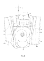
- the engine in this embodiment is water-cooled. Therefore, as shown in FIG. 9 , a radiator 54 is disposed to the right of the engine unit 22.
- the engine unit 22 comprises a cylinder component 56.
- the cylinder component 56 guides the linear reciprocal motion of a piston.
- the axis L1 of the cylinder component 56 is inclined with respect to the front-to-rear direction of the vehicle.
- the axis L1 extends upward and forward.
- the front end of the cylinder component 56 is located higher than the rear end of the cylinder component 56.
- the axis L1 is the center axis of the spaced formed in the cylinder component 56 in which the piston moves reciprocally.
- the cylinder component 56 includes a cylinder body 56A and a cylinder head 56B.
- the cylinder body 56A is disposed at the front end of a crankcase 57 that houses a crankshaft.
- the piston is disposed inside the cylinder body 56A.
- the cylinder head 56B is disposed at the front end of the cylinder body 56A.
- the cylinder head 56B includes a head main body 58 and a head cover 60.
- the head main body 58 is disposed at the front end of the cylinder body 56A.
- the head main body 58 forms a combustion chamber along with the piston.
- the head cover 60 is disposed at the front end of the head main body 58.
- an intake passage 58A and an exhaust passage 58B are formed in the head main body 58.
- An intake valve 62A is disposed in the intake passage 58A.
- two intake valves 62A are provided.
- An exhaust valve 62B is disposed in the exhaust passage 58B.
- two exhaust valves 62B are provided.
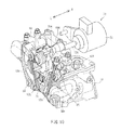
- a camshaft 64 is disposed in the head main body 58. The camshaft 64 extends in the left and right direction of the vehicle.
- the hatched surfaces are a cross section. That is, FIG. 10 is a diagram illustrating the internal structure of the head main body 58.
- the intake passage 58A is connected to the combustion chamber via a connection opening.
- the intake passage 58A is connected to the combustion chamber via two connection openings.
- the connection openings are opened and closed by the intake valves 62A. More specifically, as the camshaft 64 rotates, a rocker arm 66 pivots. Consequently, the intake valves 62A open and close the connection openings.
- the exhaust passage 58B is connected to the combustion chamber via a connection opening.
- the exhaust passage 58B is connected to the combustion chamber via two connection openings.
- the connection openings are opened and closed by the exhaust valves 62B. More specifically, as the camshaft 64 rotates, a rocker arm 68 pivots. Consequently, the exhaust valves 62B open and close the connection openings.
- the engine unit 22 further comprises a variable valve mechanism 70.
- the variable valve mechanism 70 switches the amount of displacement of the intake valves 62A. In the example shown in FIG. 10 , the variable valve mechanism 70 switches the amount of displacement of the two intake valves 62A.
- the variable valve mechanism 70 includes a solenoid 72, a switch pin 74, a coil spring 76, and a rocker arm 78.
- the solenoid 72 includes an output shaft 72A.
- the output shaft 72A is disposed so as to be capable of moving in a reciprocating manner in the left and right direction of the vehicle.
- the solenoid 72 is attached to the cylinder head 56B. More specifically, as shown in FIGS. 6 to 9 , the solenoid 72 is attached to the head cover 60.
- the solenoid 72 is disposed to the right of the axis L1 in a plan view of the vehicle.
- the solenoid 72 is disposed between the cylinder head 56B and the lower-right frame 18B in a plan view of the vehicle. More specifically, the solenoid 72 is disposed between the head cover 60 and the lower-right frame 18B in a plan view of the vehicle.
- the solenoid 72 is disposed to the left of the inclined part 32C in the left and right direction of the vehicle.
- the solenoid 72 is disposed closer to the lower-right frame 18B than a reference line L2 in the left and right direction of the vehicle.
- the reference line L2 extends in a top-to-bottom direction and passes through the center of the fuel tank 24 in the left and right direction of the vehicle.
- the solenoid 72 is superposed with the fuel tank 24 in a front view of the vehicle.
- FIG. 9 shows a state in which no rider is mounted, and the vehicle is erect.
- the position of the engine unit 22 at this point will be described below as the position when the engine unit 22 has not pivoted.
- the solenoid 72 is located ahead of the inclined part 32C in a side view of the vehicle.
- the solenoid 72 is located ahead of the right reinforcing frame 18C in a side view of the vehicle.
- the solenoid 72 is located above the axis L1 in a side view of the vehicle.
- the solenoid 72 pivots along with the engine unit 22.
- the arrow BB indicates the pivot direction of the solenoid 72.
- the rear part of the engine unit 22 is supported on the body frame 14 by a rear suspension 90.
- the rear suspension 90 is able to expand and contract.
- the rear suspension 90 expands and contracts under impact from the road surface, and cushions these impacts.
- the rear suspension 90 contracts when the rider mounts, for example.
- the solenoid 72 moves closer to the inclined part 32C in a side view of the vehicle.
- the solenoid 72 moves away from the inclined part 32C in a side view of the vehicle.
- the solenoid 72 is superposed with the inclined part 32C in a side view of the vehicle when the solenoid 72 pivots toward the inclined part 32C in a side view of the vehicle.
- the amount by which the solenoid 72 pivots toward the inclined part 32C in a side view of the vehicle is greater than the amount by which the solenoid 72 pivots away from the inclined part 32C in a side view of the vehicle.
- the solenoid 72 is superposed with the inclined part 32C in a side view of the vehicle upon pivoting toward the inclined part 32C, but the solenoid 72 may be superposed with the inclined part 32C at the position where the engine unit 22 has not pivoted, for example.
- the solenoid 72 may be superposed with the inclined part 32C in a side view of the vehicle either when the engine unit 22 has already pivoted or when the engine unit 22 has not pivoted.
- the solenoid 72 may be superposed with the inclined part 32C in a side view of the vehicle at any position within the pivot range of the engine unit 22.
- the right side cover 20R is superposed with the solenoid 72 in a side view of the vehicle. More specifically, the lower-right side cover 42R is superposed with the solenoid 72 in a side view of the vehicle.
- the distance D1 between the axis of the solenoid 72 and the axis of the pivot shaft 36 in a side view of the vehicle is shorter than the distance D2 between the axis of the axle of the rear wheel 12R and the axis of the pivot shaft 36.
- the pivot shaft 36 is disposed ahead of the rear end of the cylinder head 56B in the front-to-rear direction of the vehicle. Accordingly, the distance between the axis of the solenoid 72 and the axis of the pivot shaft 36 can be shortened. As a result, the pivot range of the solenoid 72 can be made smaller.
- the rocker arm 78 is disposed next to the rocker arm 66 in the left and right direction of the vehicle.
- the rocker arm 78 has a different cam profile from that of the rocker arm 66.
- the rocker arm 66 includes a cylindrical part 66A.
- the rocker arm 78 includes a cylindrical part 78A.
- the cylindrical part 66A and the cylindrical part 78A extend in the left and right direction of the vehicle.
- the hatched surfaces are a cross section. That is, FIGS. 11 and 12 are diagrams illustrating the internal structure of the cylindrical part 66A and the cylindrical part 78A.
- the switch pin 74 is inserted into the cylindrical part 66A. In this state, the switch pin 74 is inserted through the coil spring 76. The switch pin 74 is disposed movably in the left and right direction of the vehicle.
- the switch pin 74 includes an annular stopper 74A.
- a step 66B is formed on the inner peripheral face of the cylindrical part 66A.
- the coil spring 76 is disposed between the stopper 74A and the step 66B.
- An annular stopper 82 is fixed to the inner peripheral face of the cylindrical part 66A. As shown in FIG. 11 , the biasing force of the coil spring 76 brings the stopper 74A into contact with the stopper 82. That is, the stopper 82 prevents the switch pin 74 from coming loose from the cylindrical part 66A.
- the operation of the solenoid 72 causes the output shaft 72A to push the switch pin 74 in the left and right direction of the vehicle against the biasing force of the coil spring 76. Consequently, as shown in FIG. 12 , the switch pin 74 is inserted through the cylindrical part 78A. As a result, the rocker arm 66 and the rocker arm 78 pivot integrally when the camshaft 64 rotates. The pivoting of the rocker arm 66 pushes down the two intake valves 62A. The amount of displacement of the two intake valves 62A is based on the cam profile of the rocker arm 78.
- the straddle-type vehicle 10 comprises the body frame 14, the body cover 20, the seat 21, and the engine unit 22.
- the body cover 20 covers the body frame 14.
- the seat 21 is supported by the body frame 14.
- the engine unit 22 is disposed so as to be capable of pivoting with respect to the body frame 14, and is located under the seat 21.
- the body frame 14 includes the left frame 14C (left frame component) and the right frame 14D (right frame component).
- the left frame 14C extends in the front-to-rear direction of the vehicle.
- the right frame 14D extends in the front-to-rear direction of the vehicle, and is located to the right of the left frame 14C in the left and right direction of the vehicle.
- the left frame 14C includes the middle part 30B (lower frame component) and the inclined part 30C (inclined frame component).
- the right frame 14D includes the middle part 32B (lower frame component) and the inclined part 32C (inclined frame component).
- the middle part 30B extends farther forward than the engine unit 22 in the front-to-rear direction of the vehicle.
- the middle part 32B also extends farther forward than the engine unit 22 in the front-to-rear direction of the vehicle.
- the inclined part 30C extends upward and rearward from the rear end of the middle part 30B.
- the inclined part 32C extends rearward and upward from the rear end of the middle part 32B.
- the body cover 20 includes the foot boards 44B and 46B (foot rest components).
- the foot board 44B is located lower than the seat 21, and at least part of it is superposed with the middle part 30B in a plan view of the vehicle.
- the foot board 46B is located lower than the seat 21, and at least part of it is superposed with the middle part 32B in a plan view of the vehicle.
- the engine unit 22 comprises the cylinder component 56, the two intake valves 62A (valves), and the variable valve mechanism 70.
- the two intake valves 62A open and close the intake passage 58A formed in the cylinder component 56.
- the variable valve mechanism 70 switches the amount of displacement of the two intake valves 62A.
- the variable valve mechanism 70 includes the solenoid 72.
- the solenoid 72 has the output shaft 72A.
- the solenoid 72 is disposed between the lower-right frame 18B (more specifically, the inclined part 32C) and the cylinder component 56 in a plan view of the vehicle.
- the output shaft 72A is able to move in a reciprocating manner in the left and right direction of the vehicle.
- the solenoid 72 is superposed with the inclined part 32C at the lower-right frame 18B in a side view of the vehicle, within the pivot range of the engine unit 22. That is, the solenoid 72 is superposed with the inclined part 32C at the lower-right frame 18B in a side view of the vehicle at any position within the pivot range of the engine unit 22.
- the solenoid 72 comprises the output shaft 72A.
- the output shaft 72A is able to move in a reciprocating manner in the left and right direction of the vehicle.
- the solenoid 72 is disposed to the side of the cylinder component 56.
- the variable valve mechanism 70 can transmit the drive force of the solenoid 72 to the member (the switch pin 74) that transmits the drive force of the solenoid 72, without going through any linking mechanism. Therefore, the drive force of the solenoid 72 can be reduced. That is, the solenoid 72 can be made smaller.
- the engine unit 22 is located under the seat 21.
- the solenoid 72 can be smaller with the straddle-type vehicle 10. Accordingly, the dimensions of the portion located under the seat 21 can be reduced in the left and right direction of the vehicle with the straddle-type vehicle 10. As a result, there is less of a decrease in the comfort of the rider in moving the vehicle around or in operating it when getting on it. This means that rider comfort can be maintained.
- the solenoid 72 is disposed between the cylinder component 56 and the lower-right frame 18B in a plan view of the vehicle.
- the solenoid 72 is superposed with the inclined part 32C within the pivot range of the engine unit 22 in a side view of the vehicle. Therefore, the solenoid 72 can be protected by the body frame 14.
- the solenoid 72 can be made smaller with the straddle-type vehicle 10. Therefore, even though the solenoid 72 is disposed so as to be superposed with the inclined part 32C within the pivot range of the engine unit 22 in a side view of the vehicle, that is, at any position within the pivot range of the engine unit 22, there will be less of an increase in the dimensions in the left and right direction of the vehicle of the portion located under the seat 21, and a decrease in rider comfort can be suppressed.
- the straddle-type vehicle 10 comprises the variable valve mechanism 70 and is configured such that the engine unit 22 is disposed pivotably with respect to the body frame 14, while the solenoid 72 included in the variable valve mechanism 70 can be protected and rider comfort maintained.
- the bottom cover 20B is disposed under the solenoid 72. This prevents flying stones and so forth from hitting the solenoid 72 while the vehicle is traveling. It also prevents splashed water and so forth from adhering to the solenoid 72 while the vehicle is traveling.
- the solenoid 72 is located ahead of the inclined part 32C within the pivot range of the engine unit 22 in a side view of the vehicle. That is, the solenoid 72 is located ahead of the inclined part 32C at any position within the pivot range of the engine unit 22 in a side view of the vehicle. Therefore, the solenoid 72 is protected by the body frame 14.
- the solenoid 72 is covered by the lower-right side cover 42R in a side view of the vehicle.
- the solenoid 72 is superposed with the lower-right side cover 42R in a side view of the vehicle.
- the solenoid 72 is also hidden by the lower-right side cover 42R in a side view of the vehicle. Accordingly, the solenoid 72 is protected not just by the body frame 14, but also by the body cover 20.
- the straddle-type vehicle 10 further comprises the pivot shaft 36 and the rear wheel 12R.
- the pivot shaft 36 is located ahead of the inclined part 32C in a side view of the vehicle, and supports the engine unit 22 pivotably with respect to the body frame 14.
- the rear wheel 12R is located at the rear end of the engine unit 22, and is disposed so as to be able to pivot around the pivot shaft 36 along with the engine unit 22.
- the distance D1 between the solenoid 72 and the pivot shaft 36 is shorter than the distance D2 between the rear wheel 12R and the pivot shaft 36.
- the pivot range of the engine unit 22 is determined by the pivot range of the rear wheel 12R in the up and down direction.
- the pivot range of the solenoid 72 is smaller with the above configuration. This makes it easier to protect the solenoid 72. Also, since the pivot range of the solenoid 72 is small, there is greater latitude in the layout of the other members. This helps keep the vehicle from becoming larger, which results in better rider comfort.
- the solenoid 72 is located higher than the axis L1 of the cylinder component 56 in a side view of the vehicle.
- the solenoid 72 is disposed away from the ground. Accordingly, it is less likely that flying stones or the like will hit the solenoid 72 while the vehicle is traveling. It is also less likely that splashed water or the like will adhere to the solenoid 72 while the vehicle is traveling. This makes it easier to protect the solenoid 72.
- the body cover 20 includes the guide holes 48 (guide components) and the discharge component 50.
- the guide holes 48 are formed ahead of the engine unit 22, and guide ram air into the body cover 20.
- the discharge component 50 is formed at a location that is superposed with the engine unit 22 in a side view of the vehicle. The discharge component 50 discharges to the rear the ram air guided from the guide holes 48 into the body cover 20.
- the solenoid 72 can be cooled by ram air.
- the drive force of the solenoid 72 is lowered by generated heat, but the solenoid 72 can be cooled as mentioned above in the straddle-type vehicle 10. Therefore, the solenoid 72 does not have to be made larger in order to ensure adequate drive force. As a result, this avoids an increase in the size of the portion located under the seat 21 in the left and right direction of the vehicle.
- the guide holes 48 are located lower than the seat 21 in a side view of the vehicle.
- the guide holes 48 can be formed at locations that are close to or superposed with the solenoid 72 in the up and down direction of the vehicle. This makes it easier for ram air to hit the solenoid 72. As a result, the solenoid 72 is more readily cooled. Therefore, an increase in the size of the solenoid 72 can be suppressed, which maintains rider comfort.
- the guide holes 48 are located ahead of the foot boards 44B and 46B in a side view of the vehicle.
- the ram air guided from the guide holes 48 into the body cover 20 passes under the foot boards 44B and 46B.
- ram air guided from the guide holes 48 into the body cover 20 flows rearward after being split in the left and right direction of the vehicle. Accordingly, ram air is more likely to hit the solenoid 72 disposed to the side of the cylinder component 56, and as a result, the solenoid 72 is more readily cooled. Therefore, an increase in the size of the solenoid 72 can be suppressed, which allows rider comfort to be maintained.
- the straddle-type vehicle 10 further comprises the fuel tank 24.
- the right side cover 20R is superposed with the fuel tank 24 and the solenoid 72 in a side view of the vehicle, and is disposed away from the fuel tank 24 and the solenoid 72 in the left and right direction of the vehicle.
- the two guide holes 48 are located ahead of the fuel tank 24 in a side view of the vehicle.
- the solenoid 72 is disposed closer to the right frame 14D than the center of the fuel tank 24 in the left and right direction of the vehicle.
- the solenoid 72 is easier to cool. Therefore, an increase in the size of the solenoid 72 can be suppressed, which allows driver comfort to be maintained.
- the guide holes 48 may be formed in an under-seat cover 20D.
- the under-seat cover 20D demarcates the space under the seat 21 and the space above a foot board 84 in the front-to-rear direction of the vehicle.
- the guide holes 48 are partitioned in the up and down direction by a plurality of fins 52.
- the solenoid 72 can be cooled because ram air can be guided from the guide holes 48 into the body cover 20.
- left frame component and the right frame component may be connected to each other at a component farther forward than the lower frame component.
- the body frame of the present invention should comprise a left frame component and a right frame component, but the configuration and shape thereof are not limited to what was discussed in the above embodiment.
- the body frame 14 included the upper-left frame 16A, the lower-left frame 16B, the upper-right frame 18A, and the lower-right frame 18B, but may not include the upper-left frame 16A and the upper-right frame 18A, for example.
- the lower-right frame should extend in the front-to-rear direction of the vehicle.
- the lower-right frame 18B was connected to the front frame 14B, but may instead be connected to the head pipe 14A, for example.
- the solenoid of the present invention should comprise an output shaft capable of moving in a reciprocating manner in the left and right direction of the vehicle.
- the solenoid 72 was attached to the head cover 60, but may instead be attached to the cylinder head 56B, for example.
- the solenoid 72 was disposed between the right frame 18 and the cylinder component 56 in a plan view of the vehicle, but may instead be disposed between the left frame 16 and the cylinder component 56 in a plan view of the vehicle.
- the body cover of the present invention should cover the body frame, but its configuration and shape are not limited to what was discussed in the above embodiment.
- the body cover 20 included the upper-left side cover 40L, the lower-left side cover 42L, the upper-right side cover 40R, the lower-right side cover 42R, and the front cover 20F, but may instead be constituted by a single member, for example, and the configuration may be different from that in the above embodiment.
- the foot rest component of the present invention should be formed on the body cover, but is not limited to what was given in the above embodiment.
- the foot rest component was formed on the lower-left side cover 42L and the lower-right side cover 42R, but may instead be formed on a foot rest cover connected to the lower part of the side cover, or may be formed on a cover composed of a single member that includes left and right foot boards.
- the location of the pivot shaft of the present invention is not limited to what was given in the above embodiment.
- the pivot shaft was located above the engine unit 22 in a side view of the vehicle, but may instead be located under the engine unit in a side view of the vehicle.
- the engine unit will be able to pivot around the pivot shaft located below it, and will pivot by means of the expansion and contraction of the rear suspension.
- variable valve mechanism of the present invention should be able to switch the amount of displacement of the valves disposed in the engine unit, but its configuration and so forth are not limited to what was given in the above embodiment.
- the variable valve mechanism 70 switched the amount of displacement of the intake valves 62A, but may instead switch the amount of displacement of the exhaust valves 62B.
- the amount of displacement of the two intake valves 62A was switched, but amount of displacement of just one intake valve 62A may be switched, for example.
- the variable valve mechanism of the present invention may switch between a state in which a valve can be displaced and a state in which it cannot be displaced, for example.
- the variable valve mechanism of the present invention may also switch between the amount of displacement of an intake valve and the amount of displacement of an exhaust valve.
- the guide component of the present invention should be able to guide ram air into the body cover, but its configuration and shape are not limited to what was given in the above embodiment.
- the guide holes 48 serving as the guide component were equipped with the plurality of fins 52, but the guide component may instead be a plurality of openings not equipped with fins, or may be a single opening equipped with fins.
- the guide component of the present invention may be an opening that extends in the up and down direction, or may be an opening that extends in the left and right direction. If the guide component consists of a plurality of openings, then they may be aligned in the up and down direction or in the left and right direction.
- the phrase "extends in a certain direction” encompasses not only a direction that matches said certain direction, but also one having a component of said certain direction.
- this certain direction include the front-to-rear direction, the left and right direction, the up and down direction, upward, downward, rearward and upward, forward and upward, and so forth.
Landscapes
- Engineering & Computer Science (AREA)
- Mechanical Engineering (AREA)
- General Engineering & Computer Science (AREA)
- Chemical & Material Sciences (AREA)
- Combustion & Propulsion (AREA)
- Automatic Cycles, And Cycles In General (AREA)
- Valve Device For Special Equipments (AREA)
Applications Claiming Priority (1)
| Application Number | Priority Date | Filing Date | Title |
|---|---|---|---|
| JP2013229979A JP2015090098A (ja) | 2013-11-06 | 2013-11-06 | 鞍乗型車両 |
Publications (3)
| Publication Number | Publication Date |
|---|---|
| EP2876269A2 true EP2876269A2 (de) | 2015-05-27 |
| EP2876269A3 EP2876269A3 (de) | 2016-01-13 |
| EP2876269B1 EP2876269B1 (de) | 2017-04-19 |
Family
ID=51167628
Family Applications (1)
| Application Number | Title | Priority Date | Filing Date |
|---|---|---|---|
| EP14174962.2A Active EP2876269B1 (de) | 2013-11-06 | 2014-06-30 | Grätschsitzfahrzeug |
Country Status (4)
| Country | Link |
|---|---|
| EP (1) | EP2876269B1 (de) |
| JP (1) | JP2015090098A (de) |
| ES (1) | ES2624849T3 (de) |
| TW (1) | TWI583588B (de) |
Cited By (3)
| Publication number | Priority date | Publication date | Assignee | Title |
|---|---|---|---|---|
| EP3495633A1 (de) * | 2017-12-11 | 2019-06-12 | Yamaha Hatsudoki Kabushiki Kaisha | Motor |
| WO2021165993A1 (en) * | 2020-02-21 | 2021-08-26 | Tvs Motor Company Limited | A power unit with variable valve timing system |
| WO2022118341A3 (en) * | 2020-12-03 | 2022-07-21 | Tvs Motor Company Limited | A power unit |
Families Citing this family (1)
| Publication number | Priority date | Publication date | Assignee | Title |
|---|---|---|---|---|
| JP6967092B2 (ja) | 2020-01-16 | 2021-11-17 | 本田技研工業株式会社 | 自動二輪車 |
Citations (2)
| Publication number | Priority date | Publication date | Assignee | Title |
|---|---|---|---|---|
| JP2009185639A (ja) | 2008-02-04 | 2009-08-20 | Honda Motor Co Ltd | エンジンの可変動弁装置 |
| JP2010236384A (ja) | 2009-03-30 | 2010-10-21 | Honda Motor Co Ltd | 可変動弁機構を備えたエンジン搭載車両 |
Family Cites Families (7)
| Publication number | Priority date | Publication date | Assignee | Title |
|---|---|---|---|---|
| JP2001010579A (ja) * | 1999-06-25 | 2001-01-16 | Yamaha Motor Co Ltd | 自動二輪車のフレーム構造 |
| JP4332010B2 (ja) * | 2003-10-10 | 2009-09-16 | 本田技研工業株式会社 | スクータ型車両の物品収納構造 |
| EP2472075B1 (de) * | 2009-08-24 | 2014-09-17 | Yamaha Hatsudoki Kabushiki Kaisha | Variable ventilvorrichtung, motor damit und sattelfahrzeug |
| JP5893459B2 (ja) * | 2012-03-22 | 2016-03-23 | 本田技研工業株式会社 | 鞍乗り型車両の燃料タンク及びラジエータ配置構造 |
| JP6005382B2 (ja) * | 2012-03-30 | 2016-10-12 | 本田技研工業株式会社 | 内燃機関の可変動弁装置 |
| JP5984460B2 (ja) * | 2012-03-30 | 2016-09-06 | 本田技研工業株式会社 | 内燃機関の可変動弁機構 |
| ES2553217T3 (es) * | 2013-03-25 | 2015-12-07 | Honda Motor Co., Ltd. | Aparato de válvula variable para motor de combustión interna de tipo OHC |
-
2013
- 2013-11-06 JP JP2013229979A patent/JP2015090098A/ja active Pending
-
2014
- 2014-06-30 EP EP14174962.2A patent/EP2876269B1/de active Active
- 2014-06-30 ES ES14174962.2T patent/ES2624849T3/es active Active
- 2014-07-04 TW TW103123201A patent/TWI583588B/zh active
Patent Citations (2)
| Publication number | Priority date | Publication date | Assignee | Title |
|---|---|---|---|---|
| JP2009185639A (ja) | 2008-02-04 | 2009-08-20 | Honda Motor Co Ltd | エンジンの可変動弁装置 |
| JP2010236384A (ja) | 2009-03-30 | 2010-10-21 | Honda Motor Co Ltd | 可変動弁機構を備えたエンジン搭載車両 |
Cited By (5)
| Publication number | Priority date | Publication date | Assignee | Title |
|---|---|---|---|---|
| EP3495633A1 (de) * | 2017-12-11 | 2019-06-12 | Yamaha Hatsudoki Kabushiki Kaisha | Motor |
| WO2021165993A1 (en) * | 2020-02-21 | 2021-08-26 | Tvs Motor Company Limited | A power unit with variable valve timing system |
| CN115135857A (zh) * | 2020-02-21 | 2022-09-30 | Tvs电机股份有限公司 | 具有可变气门正时系统的动力单元 |
| CN115135857B (zh) * | 2020-02-21 | 2025-05-30 | Tvs电机股份有限公司 | 具有可变气门正时系统的动力单元 |
| WO2022118341A3 (en) * | 2020-12-03 | 2022-07-21 | Tvs Motor Company Limited | A power unit |
Also Published As
| Publication number | Publication date |
|---|---|
| JP2015090098A (ja) | 2015-05-11 |
| TW201518158A (zh) | 2015-05-16 |
| EP2876269B1 (de) | 2017-04-19 |
| TWI583588B (zh) | 2017-05-21 |
| ES2624849T3 (es) | 2017-07-17 |
| EP2876269A3 (de) | 2016-01-13 |
Similar Documents
| Publication | Publication Date | Title |
|---|---|---|
| JP4815477B2 (ja) | 自動二輪車の排気ガスセンサの取付け構造 | |
| CN102695645B (zh) | 骑乘型车辆的蒸发燃料控制装置 | |
| EP2876269B1 (de) | Grätschsitzfahrzeug | |
| CN108698498B (zh) | 三轮跨骑座椅式车辆族系 | |
| CN108698664B (zh) | 三轮跨骑座椅式车辆 | |
| EP1514787B1 (de) | Schwingarmaufhängung | |
| CN101275475B (zh) | 车辆用v型发动机 | |
| EP1972534B1 (de) | Motorrad | |
| US9068538B2 (en) | Intake system for internal combustion engine | |
| US7426788B2 (en) | Tilt angle sensor layout structure for a vehicle, and vehicle incorporating same | |
| EP3121421B1 (de) | Grätschsitzfahrzeug | |
| EP1491436B1 (de) | Lenkungsdämpfer für ein Zweiradfahrzeug | |
| EP2048074B1 (de) | Dämpfereinstellung für Motorrad | |
| JP6690218B2 (ja) | 鞍乗型車両 | |
| CN1975142B (zh) | 内燃机和二轮摩托车 | |
| JP2011025763A (ja) | 自動二輪車 | |
| EP4116553B1 (de) | Sattelfahrzeugs mit verbrennungsmotor und einlasssteuervorrichtung | |
| JP7185598B2 (ja) | 鞍乗り型車両 | |
| EP1747983B1 (de) | Niederflurfahrzeug | |
| EP3326898B1 (de) | Grätschsitzfahrzeug | |
| EP2781441B1 (de) | Sattelfahrzeug | |
| JP6121207B2 (ja) | Ohc型内燃機関の可変動弁装置 | |
| JP2021008854A (ja) | 内燃機関構造 |
Legal Events
| Date | Code | Title | Description |
|---|---|---|---|
| PUAI | Public reference made under article 153(3) epc to a published international application that has entered the european phase |
Free format text: ORIGINAL CODE: 0009012 |
|
| 17P | Request for examination filed |
Effective date: 20140630 |
|
| AK | Designated contracting states |
Kind code of ref document: A2 Designated state(s): AL AT BE BG CH CY CZ DE DK EE ES FI FR GB GR HR HU IE IS IT LI LT LU LV MC MK MT NL NO PL PT RO RS SE SI SK SM TR |
|
| AX | Request for extension of the european patent |
Extension state: BA ME |
|
| PUAL | Search report despatched |
Free format text: ORIGINAL CODE: 0009013 |
|
| AK | Designated contracting states |
Kind code of ref document: A3 Designated state(s): AL AT BE BG CH CY CZ DE DK EE ES FI FR GB GR HR HU IE IS IT LI LT LU LV MC MK MT NL NO PL PT RO RS SE SI SK SM TR |
|
| AX | Request for extension of the european patent |
Extension state: BA ME |
|
| RIC1 | Information provided on ipc code assigned before grant |
Ipc: F02B 61/02 20060101ALI20151210BHEP Ipc: F01L 1/26 20060101ALI20151210BHEP Ipc: F02B 75/16 20060101ALI20151210BHEP Ipc: F01L 1/18 20060101ALI20151210BHEP Ipc: B62K 11/04 20060101ALI20151210BHEP Ipc: F01L 13/00 20060101AFI20151210BHEP |
|
| R17P | Request for examination filed (corrected) |
Effective date: 20160713 |
|
| RBV | Designated contracting states (corrected) |
Designated state(s): AL AT BE BG CH CY CZ DE DK EE ES FI FR GB GR HR HU IE IS IT LI LT LU LV MC MK MT NL NO PL PT RO RS SE SI SK SM TR |
|
| GRAP | Despatch of communication of intention to grant a patent |
Free format text: ORIGINAL CODE: EPIDOSNIGR1 |
|
| INTG | Intention to grant announced |
Effective date: 20161221 |
|
| GRAS | Grant fee paid |
Free format text: ORIGINAL CODE: EPIDOSNIGR3 |
|
| GRAA | (expected) grant |
Free format text: ORIGINAL CODE: 0009210 |
|
| AK | Designated contracting states |
Kind code of ref document: B1 Designated state(s): AL AT BE BG CH CY CZ DE DK EE ES FI FR GB GR HR HU IE IS IT LI LT LU LV MC MK MT NL NO PL PT RO RS SE SI SK SM TR |
|
| REG | Reference to a national code |
Ref country code: GB Ref legal event code: FG4D |
|
| REG | Reference to a national code |
Ref country code: CH Ref legal event code: EP |
|
| REG | Reference to a national code |
Ref country code: AT Ref legal event code: REF Ref document number: 886186 Country of ref document: AT Kind code of ref document: T Effective date: 20170515 |
|
| REG | Reference to a national code |
Ref country code: IE Ref legal event code: FG4D |
|
| REG | Reference to a national code |
Ref country code: DE Ref legal event code: R096 Ref document number: 602014008686 Country of ref document: DE |
|
| REG | Reference to a national code |
Ref country code: FR Ref legal event code: PLFP Year of fee payment: 4 |
|
| REG | Reference to a national code |
Ref country code: ES Ref legal event code: FG2A Ref document number: 2624849 Country of ref document: ES Kind code of ref document: T3 Effective date: 20170717 |
|
| REG | Reference to a national code |
Ref country code: NL Ref legal event code: MP Effective date: 20170419 |
|
| REG | Reference to a national code |
Ref country code: LT Ref legal event code: MG4D |
|
| REG | Reference to a national code |
Ref country code: AT Ref legal event code: MK05 Ref document number: 886186 Country of ref document: AT Kind code of ref document: T Effective date: 20170419 |
|
| PG25 | Lapsed in a contracting state [announced via postgrant information from national office to epo] |
Ref country code: NL Free format text: LAPSE BECAUSE OF FAILURE TO SUBMIT A TRANSLATION OF THE DESCRIPTION OR TO PAY THE FEE WITHIN THE PRESCRIBED TIME-LIMIT Effective date: 20170419 |
|
| PG25 | Lapsed in a contracting state [announced via postgrant information from national office to epo] |
Ref country code: NO Free format text: LAPSE BECAUSE OF FAILURE TO SUBMIT A TRANSLATION OF THE DESCRIPTION OR TO PAY THE FEE WITHIN THE PRESCRIBED TIME-LIMIT Effective date: 20170719 Ref country code: HR Free format text: LAPSE BECAUSE OF FAILURE TO SUBMIT A TRANSLATION OF THE DESCRIPTION OR TO PAY THE FEE WITHIN THE PRESCRIBED TIME-LIMIT Effective date: 20170419 Ref country code: GR Free format text: LAPSE BECAUSE OF FAILURE TO SUBMIT A TRANSLATION OF THE DESCRIPTION OR TO PAY THE FEE WITHIN THE PRESCRIBED TIME-LIMIT Effective date: 20170720 Ref country code: LT Free format text: LAPSE BECAUSE OF FAILURE TO SUBMIT A TRANSLATION OF THE DESCRIPTION OR TO PAY THE FEE WITHIN THE PRESCRIBED TIME-LIMIT Effective date: 20170419 Ref country code: AT Free format text: LAPSE BECAUSE OF FAILURE TO SUBMIT A TRANSLATION OF THE DESCRIPTION OR TO PAY THE FEE WITHIN THE PRESCRIBED TIME-LIMIT Effective date: 20170419 Ref country code: FI Free format text: LAPSE BECAUSE OF FAILURE TO SUBMIT A TRANSLATION OF THE DESCRIPTION OR TO PAY THE FEE WITHIN THE PRESCRIBED TIME-LIMIT Effective date: 20170419 |
|
| PG25 | Lapsed in a contracting state [announced via postgrant information from national office to epo] |
Ref country code: IS Free format text: LAPSE BECAUSE OF FAILURE TO SUBMIT A TRANSLATION OF THE DESCRIPTION OR TO PAY THE FEE WITHIN THE PRESCRIBED TIME-LIMIT Effective date: 20170819 Ref country code: LV Free format text: LAPSE BECAUSE OF FAILURE TO SUBMIT A TRANSLATION OF THE DESCRIPTION OR TO PAY THE FEE WITHIN THE PRESCRIBED TIME-LIMIT Effective date: 20170419 Ref country code: PL Free format text: LAPSE BECAUSE OF FAILURE TO SUBMIT A TRANSLATION OF THE DESCRIPTION OR TO PAY THE FEE WITHIN THE PRESCRIBED TIME-LIMIT Effective date: 20170419 Ref country code: BG Free format text: LAPSE BECAUSE OF FAILURE TO SUBMIT A TRANSLATION OF THE DESCRIPTION OR TO PAY THE FEE WITHIN THE PRESCRIBED TIME-LIMIT Effective date: 20170719 Ref country code: SE Free format text: LAPSE BECAUSE OF FAILURE TO SUBMIT A TRANSLATION OF THE DESCRIPTION OR TO PAY THE FEE WITHIN THE PRESCRIBED TIME-LIMIT Effective date: 20170419 Ref country code: RS Free format text: LAPSE BECAUSE OF FAILURE TO SUBMIT A TRANSLATION OF THE DESCRIPTION OR TO PAY THE FEE WITHIN THE PRESCRIBED TIME-LIMIT Effective date: 20170419 |
|
| REG | Reference to a national code |
Ref country code: DE Ref legal event code: R097 Ref document number: 602014008686 Country of ref document: DE |
|
| PG25 | Lapsed in a contracting state [announced via postgrant information from national office to epo] |
Ref country code: RO Free format text: LAPSE BECAUSE OF FAILURE TO SUBMIT A TRANSLATION OF THE DESCRIPTION OR TO PAY THE FEE WITHIN THE PRESCRIBED TIME-LIMIT Effective date: 20170419 Ref country code: MC Free format text: LAPSE BECAUSE OF FAILURE TO SUBMIT A TRANSLATION OF THE DESCRIPTION OR TO PAY THE FEE WITHIN THE PRESCRIBED TIME-LIMIT Effective date: 20170419 Ref country code: DK Free format text: LAPSE BECAUSE OF FAILURE TO SUBMIT A TRANSLATION OF THE DESCRIPTION OR TO PAY THE FEE WITHIN THE PRESCRIBED TIME-LIMIT Effective date: 20170419 Ref country code: SK Free format text: LAPSE BECAUSE OF FAILURE TO SUBMIT A TRANSLATION OF THE DESCRIPTION OR TO PAY THE FEE WITHIN THE PRESCRIBED TIME-LIMIT Effective date: 20170419 Ref country code: EE Free format text: LAPSE BECAUSE OF FAILURE TO SUBMIT A TRANSLATION OF THE DESCRIPTION OR TO PAY THE FEE WITHIN THE PRESCRIBED TIME-LIMIT Effective date: 20170419 Ref country code: CZ Free format text: LAPSE BECAUSE OF FAILURE TO SUBMIT A TRANSLATION OF THE DESCRIPTION OR TO PAY THE FEE WITHIN THE PRESCRIBED TIME-LIMIT Effective date: 20170419 |
|
| REG | Reference to a national code |
Ref country code: CH Ref legal event code: PL |
|
| PLBE | No opposition filed within time limit |
Free format text: ORIGINAL CODE: 0009261 |
|
| STAA | Information on the status of an ep patent application or granted ep patent |
Free format text: STATUS: NO OPPOSITION FILED WITHIN TIME LIMIT |
|
| PG25 | Lapsed in a contracting state [announced via postgrant information from national office to epo] |
Ref country code: SM Free format text: LAPSE BECAUSE OF FAILURE TO SUBMIT A TRANSLATION OF THE DESCRIPTION OR TO PAY THE FEE WITHIN THE PRESCRIBED TIME-LIMIT Effective date: 20170419 |
|
| 26N | No opposition filed |
Effective date: 20180122 |
|
| REG | Reference to a national code |
Ref country code: IE Ref legal event code: MM4A |
|
| PG25 | Lapsed in a contracting state [announced via postgrant information from national office to epo] |
Ref country code: LI Free format text: LAPSE BECAUSE OF NON-PAYMENT OF DUE FEES Effective date: 20170630 Ref country code: LU Free format text: LAPSE BECAUSE OF NON-PAYMENT OF DUE FEES Effective date: 20170630 Ref country code: IE Free format text: LAPSE BECAUSE OF NON-PAYMENT OF DUE FEES Effective date: 20170630 Ref country code: CH Free format text: LAPSE BECAUSE OF NON-PAYMENT OF DUE FEES Effective date: 20170630 |
|
| PG25 | Lapsed in a contracting state [announced via postgrant information from national office to epo] |
Ref country code: SI Free format text: LAPSE BECAUSE OF FAILURE TO SUBMIT A TRANSLATION OF THE DESCRIPTION OR TO PAY THE FEE WITHIN THE PRESCRIBED TIME-LIMIT Effective date: 20170419 |
|
| REG | Reference to a national code |
Ref country code: BE Ref legal event code: MM Effective date: 20170630 |
|
| REG | Reference to a national code |
Ref country code: FR Ref legal event code: PLFP Year of fee payment: 5 |
|
| PG25 | Lapsed in a contracting state [announced via postgrant information from national office to epo] |
Ref country code: BE Free format text: LAPSE BECAUSE OF NON-PAYMENT OF DUE FEES Effective date: 20170630 |
|
| PG25 | Lapsed in a contracting state [announced via postgrant information from national office to epo] |
Ref country code: MT Free format text: LAPSE BECAUSE OF NON-PAYMENT OF DUE FEES Effective date: 20170630 |
|
| GBPC | Gb: european patent ceased through non-payment of renewal fee |
Effective date: 20180630 |
|
| PG25 | Lapsed in a contracting state [announced via postgrant information from national office to epo] |
Ref country code: GB Free format text: LAPSE BECAUSE OF NON-PAYMENT OF DUE FEES Effective date: 20180630 |
|
| PG25 | Lapsed in a contracting state [announced via postgrant information from national office to epo] |
Ref country code: HU Free format text: LAPSE BECAUSE OF FAILURE TO SUBMIT A TRANSLATION OF THE DESCRIPTION OR TO PAY THE FEE WITHIN THE PRESCRIBED TIME-LIMIT; INVALID AB INITIO Effective date: 20140630 |
|
| PG25 | Lapsed in a contracting state [announced via postgrant information from national office to epo] |
Ref country code: CY Free format text: LAPSE BECAUSE OF FAILURE TO SUBMIT A TRANSLATION OF THE DESCRIPTION OR TO PAY THE FEE WITHIN THE PRESCRIBED TIME-LIMIT Effective date: 20170419 |
|
| PG25 | Lapsed in a contracting state [announced via postgrant information from national office to epo] |
Ref country code: MK Free format text: LAPSE BECAUSE OF FAILURE TO SUBMIT A TRANSLATION OF THE DESCRIPTION OR TO PAY THE FEE WITHIN THE PRESCRIBED TIME-LIMIT Effective date: 20170419 |
|
| PG25 | Lapsed in a contracting state [announced via postgrant information from national office to epo] |
Ref country code: TR Free format text: LAPSE BECAUSE OF FAILURE TO SUBMIT A TRANSLATION OF THE DESCRIPTION OR TO PAY THE FEE WITHIN THE PRESCRIBED TIME-LIMIT Effective date: 20170419 |
|
| PG25 | Lapsed in a contracting state [announced via postgrant information from national office to epo] |
Ref country code: PT Free format text: LAPSE BECAUSE OF FAILURE TO SUBMIT A TRANSLATION OF THE DESCRIPTION OR TO PAY THE FEE WITHIN THE PRESCRIBED TIME-LIMIT Effective date: 20170419 |
|
| PG25 | Lapsed in a contracting state [announced via postgrant information from national office to epo] |
Ref country code: AL Free format text: LAPSE BECAUSE OF FAILURE TO SUBMIT A TRANSLATION OF THE DESCRIPTION OR TO PAY THE FEE WITHIN THE PRESCRIBED TIME-LIMIT Effective date: 20170419 |
|
| PGFP | Annual fee paid to national office [announced via postgrant information from national office to epo] |
Ref country code: ES Payment date: 20200825 Year of fee payment: 7 |
|
| REG | Reference to a national code |
Ref country code: ES Ref legal event code: FD2A Effective date: 20220902 |
|
| PG25 | Lapsed in a contracting state [announced via postgrant information from national office to epo] |
Ref country code: ES Free format text: LAPSE BECAUSE OF NON-PAYMENT OF DUE FEES Effective date: 20210701 |
|
| P01 | Opt-out of the competence of the unified patent court (upc) registered |
Effective date: 20230527 |
|
| PGFP | Annual fee paid to national office [announced via postgrant information from national office to epo] |
Ref country code: DE Payment date: 20250618 Year of fee payment: 12 |
|
| PGFP | Annual fee paid to national office [announced via postgrant information from national office to epo] |
Ref country code: FR Payment date: 20250625 Year of fee payment: 12 |
|
| PGFP | Annual fee paid to national office [announced via postgrant information from national office to epo] |
Ref country code: IT Payment date: 20250624 Year of fee payment: 12 |