EP2876268A1 - Combined power device and method for operating combined power device - Google Patents
Combined power device and method for operating combined power device Download PDFInfo
- Publication number
- EP2876268A1 EP2876268A1 EP13822137.9A EP13822137A EP2876268A1 EP 2876268 A1 EP2876268 A1 EP 2876268A1 EP 13822137 A EP13822137 A EP 13822137A EP 2876268 A1 EP2876268 A1 EP 2876268A1
- Authority
- EP
- European Patent Office
- Prior art keywords
- steam
- cycle apparatus
- expansion machine
- rankine cycle
- pressure
- Prior art date
- Legal status (The legal status is an assumption and is not a legal conclusion. Google has not performed a legal analysis and makes no representation as to the accuracy of the status listed.)
- Granted
Links
- 238000000034 method Methods 0.000 title claims description 10
- 239000000498 cooling water Substances 0.000 claims description 55
- 238000005259 measurement Methods 0.000 claims description 32
- 238000001816 cooling Methods 0.000 claims description 8
- 239000007788 liquid Substances 0.000 claims description 7
- 230000001105 regulatory effect Effects 0.000 description 33
- 230000005611 electricity Effects 0.000 description 20
- 230000007423 decrease Effects 0.000 description 13
- 230000003247 decreasing effect Effects 0.000 description 9
- 230000000694 effects Effects 0.000 description 5
- 238000012546 transfer Methods 0.000 description 5
- 229920006395 saturated elastomer Polymers 0.000 description 4
- 238000009835 boiling Methods 0.000 description 3
- 238000009434 installation Methods 0.000 description 3
- VLKZOEOYAKHREP-UHFFFAOYSA-N n-Hexane Chemical compound CCCCCC VLKZOEOYAKHREP-UHFFFAOYSA-N 0.000 description 3
- 238000011017 operating method Methods 0.000 description 3
- 238000010248 power generation Methods 0.000 description 3
- 238000011144 upstream manufacturing Methods 0.000 description 3
- XLYOFNOQVPJJNP-UHFFFAOYSA-N water Substances O XLYOFNOQVPJJNP-UHFFFAOYSA-N 0.000 description 3
- 238000012986 modification Methods 0.000 description 2
- 230000004048 modification Effects 0.000 description 2
- 239000003960 organic solvent Substances 0.000 description 2
- 238000006243 chemical reaction Methods 0.000 description 1
- LYKJEJVAXSGWAJ-UHFFFAOYSA-N compactone Natural products CC1(C)CCCC2(C)C1CC(=O)C3(O)CC(C)(CCC23)C=C LYKJEJVAXSGWAJ-UHFFFAOYSA-N 0.000 description 1
- 230000001276 controlling effect Effects 0.000 description 1
- NBVXSUQYWXRMNV-UHFFFAOYSA-N fluoromethane Chemical compound FC NBVXSUQYWXRMNV-UHFFFAOYSA-N 0.000 description 1
- 238000010438 heat treatment Methods 0.000 description 1
- 239000008236 heating water Substances 0.000 description 1
- 238000005342 ion exchange Methods 0.000 description 1
- 238000004519 manufacturing process Methods 0.000 description 1
- 238000012545 processing Methods 0.000 description 1
Images


Classifications
-
- F—MECHANICAL ENGINEERING; LIGHTING; HEATING; WEAPONS; BLASTING
- F01—MACHINES OR ENGINES IN GENERAL; ENGINE PLANTS IN GENERAL; STEAM ENGINES
- F01K—STEAM ENGINE PLANTS; STEAM ACCUMULATORS; ENGINE PLANTS NOT OTHERWISE PROVIDED FOR; ENGINES USING SPECIAL WORKING FLUIDS OR CYCLES
- F01K23/00—Plants characterised by more than one engine delivering power external to the plant, the engines being driven by different fluids
- F01K23/02—Plants characterised by more than one engine delivering power external to the plant, the engines being driven by different fluids the engine cycles being thermally coupled
- F01K23/04—Plants characterised by more than one engine delivering power external to the plant, the engines being driven by different fluids the engine cycles being thermally coupled condensation heat from one cycle heating the fluid in another cycle
-
- F—MECHANICAL ENGINEERING; LIGHTING; HEATING; WEAPONS; BLASTING
- F01—MACHINES OR ENGINES IN GENERAL; ENGINE PLANTS IN GENERAL; STEAM ENGINES
- F01K—STEAM ENGINE PLANTS; STEAM ACCUMULATORS; ENGINE PLANTS NOT OTHERWISE PROVIDED FOR; ENGINES USING SPECIAL WORKING FLUIDS OR CYCLES
- F01K13/00—General layout or general methods of operation of complete plants
- F01K13/02—Controlling, e.g. stopping or starting
-
- F—MECHANICAL ENGINEERING; LIGHTING; HEATING; WEAPONS; BLASTING
- F01—MACHINES OR ENGINES IN GENERAL; ENGINE PLANTS IN GENERAL; STEAM ENGINES
- F01K—STEAM ENGINE PLANTS; STEAM ACCUMULATORS; ENGINE PLANTS NOT OTHERWISE PROVIDED FOR; ENGINES USING SPECIAL WORKING FLUIDS OR CYCLES
- F01K25/00—Plants or engines characterised by use of special working fluids, not otherwise provided for; Plants operating in closed cycles and not otherwise provided for
- F01K25/08—Plants or engines characterised by use of special working fluids, not otherwise provided for; Plants operating in closed cycles and not otherwise provided for using special vapours
-
- F—MECHANICAL ENGINEERING; LIGHTING; HEATING; WEAPONS; BLASTING
- F01—MACHINES OR ENGINES IN GENERAL; ENGINE PLANTS IN GENERAL; STEAM ENGINES
- F01K—STEAM ENGINE PLANTS; STEAM ACCUMULATORS; ENGINE PLANTS NOT OTHERWISE PROVIDED FOR; ENGINES USING SPECIAL WORKING FLUIDS OR CYCLES
- F01K7/00—Steam engine plants characterised by the use of specific types of engine; Plants or engines characterised by their use of special steam systems, cycles or processes; Control means specially adapted for such systems, cycles or processes; Use of withdrawn or exhaust steam for feed-water heating
- F01K7/10—Steam engine plants characterised by the use of specific types of engine; Plants or engines characterised by their use of special steam systems, cycles or processes; Control means specially adapted for such systems, cycles or processes; Use of withdrawn or exhaust steam for feed-water heating characterised by the engine exhaust pressure
- F01K7/12—Steam engine plants characterised by the use of specific types of engine; Plants or engines characterised by their use of special steam systems, cycles or processes; Control means specially adapted for such systems, cycles or processes; Use of withdrawn or exhaust steam for feed-water heating characterised by the engine exhaust pressure of condensing type
- F01K7/14—Control means specially adapted therefor
-
- F—MECHANICAL ENGINEERING; LIGHTING; HEATING; WEAPONS; BLASTING
- F01—MACHINES OR ENGINES IN GENERAL; ENGINE PLANTS IN GENERAL; STEAM ENGINES
- F01K—STEAM ENGINE PLANTS; STEAM ACCUMULATORS; ENGINE PLANTS NOT OTHERWISE PROVIDED FOR; ENGINES USING SPECIAL WORKING FLUIDS OR CYCLES
- F01K9/00—Plants characterised by condensers arranged or modified to co-operate with the engines
- F01K9/003—Plants characterised by condensers arranged or modified to co-operate with the engines condenser cooling circuits
-
- Y—GENERAL TAGGING OF NEW TECHNOLOGICAL DEVELOPMENTS; GENERAL TAGGING OF CROSS-SECTIONAL TECHNOLOGIES SPANNING OVER SEVERAL SECTIONS OF THE IPC; TECHNICAL SUBJECTS COVERED BY FORMER USPC CROSS-REFERENCE ART COLLECTIONS [XRACs] AND DIGESTS
- Y02—TECHNOLOGIES OR APPLICATIONS FOR MITIGATION OR ADAPTATION AGAINST CLIMATE CHANGE
- Y02P—CLIMATE CHANGE MITIGATION TECHNOLOGIES IN THE PRODUCTION OR PROCESSING OF GOODS
- Y02P80/00—Climate change mitigation technologies for sector-wide applications
- Y02P80/10—Efficient use of energy, e.g. using compressed air or pressurized fluid as energy carrier
- Y02P80/15—On-site combined power, heat or cool generation or distribution, e.g. combined heat and power [CHP] supply
Definitions
- the present invention relates to combined power apparatuses that combine Rankine cycle apparatuses and binary cycle apparatuses, and methods of operating combined power apparatuses.
- thermodynamic cycle like this in which a steam turbine is driven by high-temperature steam to extract power is called the Rankine cycle.
- An apparatus that uses the Rankine cycle to extract power is called a Rankine cycle apparatus.
- thermodynamic cycles in which a power source that does not have an amount of heat enough to rotationally drive a steam turbine is used to generate power or generate electricity include a binary cycle.
- a binary cycle apparatus using the binary cycle uses an organic solvent having a low boiling point that evaporates at a low temperature lower than or equal to 100°C as a working medium, and is used as a secondary or auxiliary power generating system, electric generating system, or the like in a relatively small factory or the like.
- a combined power apparatus that combines a Rankine cycle apparatus for a relatively high-temperature heat source and a binary cycle apparatus for a low-temperature heat source for generating power or generating electricity with a high degree of efficiency has been hitherto conceived.
- Patent Document 1 discloses a combined power generating system that combines a gas turbine, a Rankine cycle, and a binary cycle to be able to recover power or electricity from a heat source with a high degree of efficiency.
- Patent Document 1 JP H7-166815 A
- the combined power generating system in Patent Document 1 recovers surplus thermal energy from a Rankine cycle apparatus on the high-temperature side, using a heat exchanger, and uses the recovered thermal energy to generate power or generate electricity by a binary cycle apparatus on the low-temperature side, for example.
- the pressure inside the condenser becomes close to a vacuum, causing the necessity to use an airtight structure for the condenser or causing the necessity to increase the heat-transfer area of the condenser to allow heat transfer with steam of low density (namely, liquid water), and thus the size of the condenser structure is likely to increase.
- a power generating system using renewable energy or the like is often installed individually for each small-scale user rather than being intensively installed at a place on a large scale.
- a relatively compact one is often demanded. Therefore, in consideration of wide use of a power generating system best suited to a small-scale user, not only a property of being highly efficient but also a property such as allowing easy operation or needing a small installation space, for example, are strongly demanded of the power generating system.
- Patent Document 1 is intended for a large-scale power generating system (such as a power plant) for generating commercial power, and cannot respond to such a situation.
- the present invention has been made in view of the above-described problem, and has an object of providing a combined power apparatus that can generate power or electricity with a high degree of efficiency without taking much installation space, and a method of operating the combined power apparatus.
- a combined power apparatus of the present invention takes technical means as below.
- a combined power apparatus of the present invention is a combined power apparatus that combines a Rankine cycle apparatus provided with an expansion machine that expands steam generated to generate power and a binary cycle apparatus that recovers thermal energy contained in the steam expanded by the expansion machine provided in the Rankine cycle apparatus and uses the recovered thermal energy to generate power, and is provided with a controller for adjusting the amount of thermal energy recovered from the Rankine cycle apparatus by the binary cycle apparatus so that the temperature of steam after being expanded by the expansion machine provided in the Rankine cycle apparatus becomes 100°C or higher, and/or the pressure of the steam becomes atmospheric pressure or higher.
- the expansion machine provided in the Rankine cycle apparatus expands steam generated, thereby generating a rotational driving force
- the Rankine cycle apparatus is provided with a pump for returning steam after being expanded by the expansion machine.
- the binary cycle apparatus includes a first heat exchanger for guiding steam after being expanded by the expansion machine provided in the Rankine cycle apparatus to a primary side to evaporate a working medium fed to a secondary side, an expansion machine for expanding steam of the working medium evaporated by the first heat exchanger to generate a rotational driving force, a second heat exchanger for cooling steam of the working medium expanded by the expansion machine of the binary cycle apparatus to condense the working medium to liquid, and a pump for returning the working medium from the second heat exchanger to the first heat exchanger.
- a first heat exchanger for guiding steam after being expanded by the expansion machine provided in the Rankine cycle apparatus to a primary side to evaporate a working medium fed to a secondary side
- an expansion machine for expanding steam of the working medium evaporated by the first heat exchanger to generate a rotational driving force
- a second heat exchanger for cooling steam of the working medium expanded by the expansion machine of the binary cycle apparatus to condense the working medium to liquid
- a pump for returning the working medium from the second heat exchanger to the
- the controller includes a measurement unit for measuring the temperature and/or pressure of steam circulating on the outlet side of the expansion machine provided in the Rankine cycle apparatus.
- the controller includes a working medium flow adjustment unit capable of adjusting the flow rate of the working medium circulating through the pump provided in the binary cycle apparatus, and an adjustment control unit for adjusting the flow rate of the working medium circulating through the pump provided in the binary cycle apparatus by the working medium flow adjustment unit so that the temperature of steam after being expanded by the expansion machine provided in the Rankine cycle apparatus becomes 100°C or higher, and/or the pressure of the steam becomes atmospheric pressure or higher, based on the flow rate and/or pressure of the steam measured by the measurement unit.
- the controller includes a rotational speed adjustment unit capable of adjusting the rotational speed of the expansion machine provided in the binary cycle apparatus, and an adjustment control unit for adjusting the rotational speed of the expansion machine by the rotational speed adjustment unit so that the temperature of steam after being expanded by the expansion machine provided in the Rankine cycle apparatus becomes 100°C or higher, and/or the pressure of the steam becomes atmospheric pressure or higher, based on the flow rate and/or pressure of the steam measured by the measurement unit.
- the controller includes a cooling water flow adjustment unit for adjusting the flow rate of cooling water fed to the second heat exchanger of the binary cycle apparatus, and an adjustment control unit for adjusting the flow rate of the cooling water fed to the second heat exchanger of the binary cycle apparatus by the cooling water flow adjustment unit so that the temperature of steam after being expanded by the expansion machine provided in the Rankine cycle apparatus becomes 100°C or higher, and/or the pressure of the steam becomes atmospheric pressure or higher, based on the flow rate and/or pressure of the steam measured by the measurement unit.
- the controller includes a bypass pipe that allows a portion of steam circulating through the Rankine cycle apparatus to merge with cooling water to be fed to the second heat exchanger of the binary cycle apparatus to change the temperature of the cooling water, a cooling water temperature adjustment unit for adjusting the flow rate of steam circulating through the bypass pipe and returning to the cooling water side, and an adjustment control unit for adjusting the flow rate of steam circulating through the bypass pipe by the cooling water temperature adjustment unit so that the temperature of steam after being expanded by the expansion machine provided in the Rankine cycle apparatus becomes 100°C or higher, and/or the pressure of the steam becomes atmospheric pressure or higher, based on the flow rate and/or pressure of the steam measured by the measurement unit.
- a bypass pipe that allows a portion of steam circulating through the Rankine cycle apparatus to merge with cooling water to be fed to the second heat exchanger of the binary cycle apparatus to change the temperature of the cooling water
- a cooling water temperature adjustment unit for adjusting the flow rate of steam circulating through the bypass pipe and returning to the cooling water side
- an adjustment control unit for
- a generator to which a rotational driving force generated by the expansion machine provided in the Rankine cycle apparatus and a rotational driving force generated by the expansion machine provided in the binary cycle apparatus are both transmitted is included.
- a method of operating a combined power apparatus of the present invention is a method of operating a combined power apparatus for generating power, using the above-described combined power apparatus, and includes adjusting the amount of thermal energy recovered by the binary cycle apparatus so that the temperature of steam after being expanded by the expansion machine provided in the Rankine cycle apparatus becomes 100°C or higher, and/or the pressure of steam after being expanded by the expansion machine provided in the Rankine cycle apparatus becomes atmospheric pressure or higher.
- a combined power apparatus and a method of operating a combined power apparatus of the present invention can generate power or electricity with a high degree of efficiency without taking much installation space.
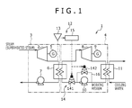
- Fig. 1 schematically illustrates a combined power apparatus 1 in a first embodiment.
- the combined power apparatus 1 in the first embodiment is a combination of a Rankine cycle apparatus 3 and a binary cycle apparatus 4.
- the Rankine cycle apparatus 3 includes an expansion machine 2 (steam turbine) for expanding steam generated to generate power.
- the binary cycle apparatus 4 generates power by recovering a portion of thermal energy contained in the steam expanded by the expansion machine 2 and using the recovered thermal energy.
- the Rankine cycle apparatus 3 is a portion provided on the left side of the space in Fig. 1 and enclosed with a chain line in the figure.
- the Rankine cycle apparatus 3 rotationally drives the expansion machine 2 (steam turbine), using superheated steam, thereby generating power or electricity.
- the expansion machine 2 steam turbine
- a power generating system that generates electric power, using power generated is illustrated.
- the Rankine cycle apparatus 3 includes an evaporator such as a boiler not shown in addition to the expansion machine 2, a generator 5, a first heat exchanger 6, and a pump 7.
- the evaporator can not only generate saturated steam by heating water (ion-exchange water or pure water), but also generate superheated steam by heating the saturated steam further. Superheated steam generated by the boiler is sent to the expansion machine 2.
- the word “first” is prefixed to the expansion machine 2, the generator 5, and the pump 7 on the Rankine cycle apparatus 3 side for designation.
- the word “second” is prefixed to an expansion machine 8, a generator 9, and a pump 10 on the side of the binary cycle apparatus 4 described below for designation. With this, confusion between members of both the cycle apparatuses is avoided.
- the expression “steam” includes not only superheated steam but also saturated steam and wet steam.
- the first expansion machine 2 (expansion machine, or a steam turbine, on the Rankine cycle apparatus side) generates a rotational driving force by expanding steam, and converts thermal energy of steam into kinetic energy.
- the first generator 5 generator on the Rankine cycle apparatus side
- the first generator 5 further generates electricity, using the rotational driving force generated by the first expansion machine 2. Steam after being expanded by the first expansion machine 2 is sent to the first heat exchanger 6.
- the first heat exchanger 6 recovers a portion of thermal energy generated by the Rankine cycle apparatus 3 for transfer to the binary cycle apparatus 4. Steam after being expanded by the first expansion machine 2 is fed to the primary side of the first heat exchanger 6, and a working medium in the binary cycle apparatus 4 described below is fed in a liquid state to the secondary side of the first heat exchanger 6. In other words, the first heat exchanger 6 also serves as a condenser for cooling and condensing steam in the Rankine cycle apparatus 3. Steam after completion of heat exchange (cooling) in the first heat exchanger 6 returns to the above-described evaporator through the first pump 7 (pump on the Rankine cycle apparatus side).
- the binary cycle apparatus 4 is a portion provided on the right side of the space in Fig. 1 , enclosed by a chain double-dashed line in the figure.
- the binary cycle apparatus 4 uses an organic solvent having a low boiling point such as an alternative fluorocarbon or hexane as a working medium, and generates a rotational driving force by expanding the working medium by the expansion machine (second expansion machine 8).
- the binary cycle apparatus 4 is also shown as a power generating system that generates electric power, using power generated like the Rankine cycle apparatus 3.
- the binary cycle apparatus 4 includes a generator (second generator 9).
- the binary cycle apparatus 4 includes the first heat exchanger 6, the second expansion machine 8, the second generator 9, a second heat exchanger 11, and the second pump 10.
- the first heat exchanger 6 cools steam in the Rankine cycle apparatus 3 while recovering thermal energy from this steam as described above, and evaporates the working medium having the low boiling point, using the recovered thermal energy. That is, the first heat exchanger 6 also serves as an evaporator of the binary cycle apparatus 4 for generating steam of the working medium.
- the steam of the working medium generated by the first heat exchanger 6 is sent to the second expansion machine 8 (expansion machine on the binary cycle apparatus side).
- the second expansion machine 8 expands the steam of the working medium, converting a portion of the thermal energy recovered from the Rankine cycle apparatus 3 side into kinetic energy, and generating a rotational driving force.
- the second generator 9 generator on the binary cycle apparatus side
- the second generator 9 also generates electricity like the first generator 5.
- the working medium after being expanded by the second expansion machine 8 is sent to the second heat exchanger 11.
- the second heat exchanger 11 cools and condenses steam of the working medium after being expanded by the second expansion machine 8, condensing the gaseous working medium into liquid.
- Steam of the working medium after being expanded by the second expansion machine 8 is fed to the primary side of the second heat exchanger 11, and cooling water is fed to the secondary side of the second heat exchanger 11 for heat exchange between them.
- the second heat exchanger 11 constitutes a condenser for condensing the working medium into liquid.
- the liquid of the working medium generated by the second heat exchanger 11 returns to the above-described first heat exchanger 6 through the second pump 10 (pump on the binary cycle apparatus side). Thereafter, the working medium evaporates again in the first heat exchanger 6, returning to gas.
- the combined power apparatus 1 that combines the Rankine cycle apparatus 3 and the binary cycle apparatus 4 as described above, first, in the Rankine cycle apparatus 3, a portion of the thermal energy of superheated steam is recovered to generate power (electricity). Then, in the binary cycle apparatus 4, thermal energy is further recovered from the steam after being expanded in the Rankine cycle apparatus 3. In other words, the binary cycle apparatus 4 recovers a portion of the remaining thermal energy that has not been able to be recovered by the Rankine cycle apparatus 3, and generates power (electricity), using the recovered thermal energy also on the binary cycle apparatus 4 side.
- power conversion efficiency and power generation efficiency become higher by the amount of power (electricity) generated by the binary cycle apparatus 4 than those when power (electricity) is generated solely by the Rankine cycle apparatus 3, allowing generation of more power or electricity.
- the combined power apparatus 1 of the present invention is provided with a controller 12 for adjusting the amount of thermal energy recovered from the Rankine cycle apparatus 3 by the binary cycle apparatus 4 so that the temperature of steam after being expanded by the first expansion machine 2 provided in the Rankine cycle apparatus 3 becomes 100°C or higher, and/or the pressure of steam becomes atmospheric pressure or higher.
- the controller 12 adjusts the amount of thermal energy recovered from the Rankine cycle apparatus 3 by the binary cycle apparatus 4 by changing the flow rate or temperature of the working medium circulating in the binary cycle apparatus 4, or changing the flow rate or temperature of the cooling water fed to the binary cycle apparatus 4.
- the controller 12 provided to the combined power apparatus 1 in the first embodiment adjusts the amount of thermal energy recovered by the binary cycle apparatus 4 by changing the flow rate of the working medium circulating through the pump provided in the binary cycle apparatus 4.
- the controller 12 includes a measurement unit 13, a working medium flow adjustment unit 14, and an adjustment control unit 15.
- the measurement unit 13 measures the temperature of steam and/or the pressure of steam circulating on the outlet side of the expansion machine 2 provided in the Rankine cycle apparatus 3.
- the working medium flow adjustment unit 14 can adjust the flow rate of the working medium circulating through the pump provided in the binary cycle apparatus 4.
- the adjustment control unit 15 sends a command to the working medium flow adjustment unit 14 so that the temperature of steam after being expanded by the expansion machine 2 provided in the Rankine cycle apparatus 3 becomes 100°C or higher, and/or the pressure of steam becomes atmospheric pressure or higher, based on the flow rate and/or pressure of steam measured by the measurement unit 13.
- the adjustment control unit 15 adjusts the flow rate of the working medium circulating through the pump (second pump 10) provided in the binary cycle apparatus 4.
- the measurement unit 13 is a temperature sensor for measuring the temperature of steam, a pressure sensor for measuring the pressure of steam, or a combination of the temperature sensor and the pressure sensor, provided in a pipe on the outlet side of the first expansion machine 2, and measures the temperature of steam and/or the pressure of steam after expansion. Measurement data on temperature and/or pressure measured by the measurement unit 13 is sent to the adjustment control unit 15 described below.
- the working medium flow adjustment unit 14 adjusts the flow rate of the working medium circulating through the second pump, and can use either of two flow regulating valves 141 and 142 as shown in the figure, or both of them.
- the first flow regulating valve 141 is a flow regulating valve of a servo type or the like that can adjust the valve opening according to a signal from the adjustment control unit 15.
- the first flow regulating valve 141 is provided in a pipe extending from the second pump 10 in the binary cycle apparatus 4 to the first heat exchanger 6, and adjusts the flow rate of the working medium circulating from the second pump 10 to the first heat exchanger 6, in other words, the circulation flow rate of the working medium circulating in the binary cycle apparatus 4.
- a bypass pipe 16 that allows the working medium to directly return to the upstream side without passing through the second pump 10 is provided between a pipe located upstream side of the second pump 10 and a pipe located downstream side in the binary cycle apparatus 4.
- the second flow regulating valve 142 is a flow regulating valve provided in the bypass pipe 16 and can adjust the valve opening according to a signal from the adjustment control unit 15, like the first flow regulating valve 141.
- the second flow regulating valve 142 like this allows adjustment of the flow rate (return flow rate) of the working medium returning from the downstream side to the upstream side of the second pump 10 through the bypass pipe 16, and consequently allows adjustment of the flow rate of the working medium circulating from the second pump 10 to the first heat exchanger 6.
- either of the two flow regulating valves 141 and 142 may be used, or both of them may be used.
- the adjustment control unit 15 sends a command to the working medium flow adjustment unit 14 so that the temperature of steam after being expanded by the first expansion machine 2 provided in the Rankine cycle apparatus 3 becomes 100°C or higher, and/or the pressure of steam becomes atmospheric pressure or higher, based on the flow rate and/or pressure of steam measured by the above-described measurement unit 13.
- the working medium flow adjustment unit 14 (first flow regulating valve and/or second flow regulating valve) adjusts the flow rate of the working medium circulating through the second pump 10 provided in the binary cycle apparatus 4.
- a personal computer or a PLC may be used.
- the temperature and/or pressure of steam circulating on the outlet side of the expansion machine 2 are measured. Measurement data on the measured temperature and/or pressure is sent to the adjustment control unit 15.
- the adjustment control unit 15 sends a command to the working medium flow adjustment unit 14. According to the command, the working medium flow adjustment unit 14 changes the flow rate of the working medium circulating from the second pump 10 to the first heat exchanger 6, thereby adjusting the amount of thermal energy recovered by the binary cycle apparatus 4.
- the pressure measured by the measurement unit 13 being "atmospheric pressure” means that absolute pressure is 0.1 MPa.
- the adjustment control unit 15 sends a command to the working medium flow adjustment unit 14.
- the working medium flow adjustment unit 14 decreases the flow rate of the working medium circulating from the second pump 10 to the first heat exchanger 6. This decreases the amount of thermal energy recovered by the binary cycle apparatus 4, and thus the amount of thermal energy in the Rankine cycle apparatus 3 does not decrease by the amount of decrease of the recovered thermal energy.
- the temperature of steam on the outlet side of the first expansion machine 2 in the Rankine cycle apparatus 3 becomes 100°C or higher, or the pressure of steam becomes atmospheric pressure or higher.
- the adjustment control unit 15 sends a command to the working medium flow adjustment unit 14.
- the working medium flow adjustment unit 14 increases the flow rate of the working medium circulating from the second pump 10 to the first heat exchanger 6. This increases the amount of thermal energy recovered by the binary cycle apparatus 4 side, and thus the temperature of steam on the outlet side of the first expansion machine 2 of the Rankine cycle apparatus 3 becomes about 100°C, and the pressure of steam becomes about atmospheric pressure.
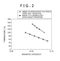
- Fig. 2 shows adiabatic efficiency in comparison between the case where only a Rankine cycle apparatus is used and the case where the Rankine cycle apparatus 3 and the binary cycle apparatus 4 are combined for use.
- electric power is generated from steam at a steam temperature of 170°C and at a pressure of 0.7 MPaA.
- Adiabatic efficiency when only the Rankine cycle apparatus is used is shown as rhombus marks in Fig. 2 .
- Fig. 2 when only the Rankine cycle apparatus is used, while the adiabatic efficiency at a steam exhaust temperature of 100°C is about 0.08, the adiabatic efficiency at 60°C increases to about 0.14.
- the adiabatic efficiency calculated in this manner is shown as square marks in Fig. 2 . From Fig. 2 , while the adiabatic efficiency when the binary inlet temperature is 150°C is about 0.1, the adiabatic efficiency when the binary inlet temperature becomes 100°C becomes about 0.13.
- an adiabatic efficiency equal to that when the temperature after expansion (steam exhaust temperature) is 60°C (the pressure is 0.08 MPaA) in the Rankine cycle apparatus 3 can be realized by the combination of the Rankine cycle apparatus 3 and the binary cycle apparatus 4 under a manageable condition that steam is at atmospheric pressure or higher.
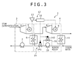
- the adjustment control unit 15 may be configured to adjust the rotational speed of the expansion machine (second expansion machine 8) provided in the binary cycle apparatus 4.
- a rotational speed adjustment unit (not shown) that can adjust the rotational speed of the expansion machine may be provided in the second generator 9 or the second expansion machine 8.
- the amount of thermal energy recovered by the binary cycle apparatus 4 can be adjusted also when the adjustment control unit 15 or the rotational speed adjustment unit applies load to the second expansion machine 8 or the second generator 9 of the binary cycle apparatus 4, decreasing the rotational speed.
- the rotational speed adjustment unit can decrease the rotational speed of the second generator 9 or the second expansion machine 8. In this way, the flow rate of the working medium varies in accordance with a variation in the rotational speed of the second expansion machine 8 or the second generator 9, thus allowing the adjustment of the amount of thermal energy recovered by the binary cycle apparatus 4.
- the first flow regulating valve 141 and the second flow regulating valve 142 used as the above-described working medium flow adjustment unit 14 have not only the function as a flow regulating valve but also the function as a pressure regulating valve.
- a controller 12 of the combined power apparatus 1 in the second embodiment adjusts the amount of thermal energy recovered by a binary cycle apparatus 4 by changing the flow rate of cooling water fed to a second heat exchanger 11 provided in the binary cycle apparatus 4.
- the controller 12 includes a cooling water flow adjustment unit 18 and an adjustment control unit 15.
- the cooling water flow adjustment unit 18 adjusts the flow rate of cooling water fed to the second heat exchanger 11 of the binary cycle apparatus 4.
- the cooling water flow adjustment unit 18 is a flow regulating valve of a servo type or the like that can adjust only the flow rate of cooling water fed to the second heat exchanger 11, and is openable and closable according to a command from the adjustment control unit 15.
- the adjustment control unit 15 sends a command to the cooling water flow adjustment unit 18 so that the temperature of steam after being expanded by the first expansion machine 2 provided in a Rankine cycle apparatus 3 becomes 100°C or higher and/or the pressure of steam becomes atmospheric pressure or higher, based on the flow rate and/or pressure of steam measured by the above-described measurement unit 13. According to this command, the cooling water flow adjustment unit 18 adjusts the flow rate of the cooling water fed to the second heat exchanger 11 provided in the binary cycle apparatus 4.
- the adjustment control unit 15 sends a command to the cooling water flow adjustment unit 18 to decrease the flow rate of the cooling water fed to the second heat exchanger 11.
- the amount of thermal energy recovered by the binary cycle apparatus 4 decreases, and the amount of thermal energy in the Rankine cycle apparatus 3 increases by the amount of decrease of the recovered thermal energy.
- the temperature of steam on the outlet side of the first expansion machine 2 of the Rankine cycle apparatus 3 becomes 100°C or higher, and the pressure of steam becomes atmospheric pressure or higher.
- the adjustment control unit 15 sends a command to the cooling water flow adjustment unit 18 to increase the flow rate of the cooling water fed to the second heat exchanger 11.
- This increases the cooling function of the second heat exchanger 11 on the working medium circulating through the binary cycle apparatus 4, decreasing the temperature of the working medium circulating through the binary cycle apparatus 4.
- the amount of thermal energy recovered by the binary cycle apparatus 4 increases, allowing efficient power (electricity) generation by the binary cycle apparatus 4.
- the combined power apparatus 1 in the second embodiment can also generate power while keeping excellent efficiency without decreasing the temperature of superheated steam to lower than 100°C or lower than or equal to atmospheric pressure.
- the controller 12 of the combined power apparatus 1 in the second embodiment may alternatively be configured to change the amount of heat taken into the binary cycle apparatus 4 by opening or closing a flow regulating valve 17 provided on the inlet side of the second expansion machine 8.
- the flow regulating valve 17 has not only the function as a flow regulating valve but also the function as a pressure regulating valve.
- a controller 12 of the combined power apparatus 1 in the third embodiment adjusts the amount of thermal energy recovered by a binary cycle apparatus 4 by changing the temperature of cooling water fed to a second heat exchanger 11 provided in the binary cycle apparatus 4.
- the controller 12 includes a bypass pipe 19, a cooling water temperature adjustment unit 20, and an adjustment control unit 15.
- the bypass pipe 19 allows a portion of steam circulating through a Rankine cycle apparatus 3 to merge with cooling water to be fed to the second heat exchanger 11 of the binary cycle apparatus 4, thereby changing the temperature of the cooling water.
- the cooling water temperature adjustment unit 20 adjusts the flow rate of steam circulating through the bypass pipe 19 and returning to the cooling water side.
- the adjustment control unit 15 sends a command to the cooling water temperature adjustment unit 20 so that the temperature of steam after being expanded by the expansion machine 2 provided in the Rankine cycle apparatus 3 becomes 100°C or higher, and/or the pressure of steam becomes atmospheric pressure or higher, based on the flow rate and/or pressure of steam measured by a measurement unit 13.
- the bypass pipe 19 connects between the downstream side of a first pump 7 of the Rankine cycle apparatus 3 and a pipe feeding the cooling water to the second heat exchanger 11 of the binary cycle apparatus 4.
- the bypass pipe 19 allows a portion of steam after exchanging heat in the first heat exchanger 6 of the Rankine cycle apparatus 3 by a predetermined amount to merge with the cooling water to be fed to the second heat exchanger 11 of the binary cycle apparatus 4. This allows the temperature adjustment of the cooling water.
- the cooling water temperature adjustment unit 20 in the third embodiment also constitutes a flow regulating valve that can adjust the flow rate of steam circulating through the bypass pipe 19.
- the cooling water temperature adjustment unit 20 the above-described first flow regulating valve 201 provided in the bypass pipe 19, a second flow regulating valve 202 provided in a steam pipe located downstream side of a bifurcation position of the bypass pipe 19, or both of the first flow regulating valve 201 and the second flow regulating valve 202 can be used.
- Either of the first flow regulating valve 201 and the second flow regulating valve 202 is a flow regulating valve of a servo type or the like that can adjust the temperature of the cooling water fed to the second heat exchanger 11, and is made openable and closable according to a command from the adjustment control unit 15.
- the adjustment control unit 15 sends a command to the cooling water temperature adjustment unit 20 so that the temperature of steam after being expanded by the first expansion machine 2 provided in the Rankine cycle apparatus 3 becomes 100°C or higher, and/or the pressure of the steam becomes atmospheric pressure or higher, based on the flow rate and/or pressure of steam measured by the above-described measurement unit 13. According to this command, the cooling water temperature adjustment unit 20 changes the flow rate of steam returned through the bypass pipe 19, thereby adjusting the temperature of the cooling water fed to the second heat exchanger 11.
- the adjustment control unit 15 sends a command to the cooling water temperature adjustment unit 20 to increase the flow rate of steam circulating through the bypass pipe 19.
- This increases the flow rate of steam circulating through the bypass pipe 19, lowering the cooling function of the second heat exchanger 11 on a working medium circulating through the binary cycle apparatus 4, and increasing the temperature of the working medium circulating through the binary cycle apparatus 4.
- the amount of thermal energy recovered by the binary cycle apparatus 4 decreases, and the amount of thermal energy of the Rankine cycle apparatus 3 increases by the amount of decrease of the recovered thermal energy.
- the temperature of steam on the outlet side of the first expansion machine 2 of the Rankine cycle apparatus 3 becomes 100°C or higher, and the pressure of steam becomes atmospheric pressure or higher.
- the adjustment control unit 15 sends a command to the cooling water temperature adjustment unit 20 to decrease the flow rate of the cooling water circulating through the bypass pipe 19.
- the amount of thermal energy recovered by the binary cycle apparatus 4 increases, and the binary cycle apparatus 4 can efficiently generate power (electricity).
- the combined power apparatus 1 in the third embodiment can also generate power (electricity) while keeping excellent efficiency without decreasing the temperature of superheated steam to lower than 100°C or lower than or equal to atmospheric pressure.
- the combined power apparatus 1 in the fourth embodiment includes a generator 21 to which a rotational driving force generated by an expansion machine 2 of a Rankine cycle apparatus 3 and a rotational driving force generated by an expansion machine 8 of a binary cycle apparatus 4 are both transmitted.
- the generator 21 is solely provided in the combined power apparatus 1 in the fourth embodiment, and is configured to serve both the function of the first generator 5 of the Rankine cycle apparatus 3 and the function of the second generator 9 of the binary cycle apparatus 4.
- the generator 21 in the fourth embodiment is interposed between a rotating shaft of the first expansion machine 2 and a rotating shaft of the second expansion machine 8, and includes a turbine in a position coaxial with either of the two rotating shafts.
- a rotational driving force generated by the first expansion machine 2 and a rotational driving force generated by the second expansion machine 8 are both transmitted to the generator 21, which generates power (electricity) corresponding to a driving force to which these sum up (sum total).
- This configuration needs only one system of a generator, wiring to send out electricity from the generator, a device controlling the generator, or the like, allowing a further simplified device configuration of the combined power apparatus 1.
Landscapes
- Engineering & Computer Science (AREA)
- Chemical & Material Sciences (AREA)
- Combustion & Propulsion (AREA)
- Mechanical Engineering (AREA)
- General Engineering & Computer Science (AREA)
- Engine Equipment That Uses Special Cycles (AREA)
- Control Of Turbines (AREA)
Abstract
Description
- The present invention relates to combined power apparatuses that combine Rankine cycle apparatuses and binary cycle apparatuses, and methods of operating combined power apparatuses.
- Conventionally, in thermal, nuclear, or other power plants, heat generated from a heat source is recovered to rotationally drive a steam turbine, and a rotational driving force generated is used for electric power generation. In manufacturing sites or the like, in some cases, steam generated by a boiler or the like is used as a power source to rotationally drive a steam turbine. A thermodynamic cycle like this in which a steam turbine is driven by high-temperature steam to extract power is called the Rankine cycle. An apparatus that uses the Rankine cycle to extract power is called a Rankine cycle apparatus.
- On the other hand, thermodynamic cycles in which a power source that does not have an amount of heat enough to rotationally drive a steam turbine is used to generate power or generate electricity include a binary cycle. A binary cycle apparatus using the binary cycle uses an organic solvent having a low boiling point that evaporates at a low temperature lower than or equal to 100°C as a working medium, and is used as a secondary or auxiliary power generating system, electric generating system, or the like in a relatively small factory or the like.
- A combined power apparatus that combines a Rankine cycle apparatus for a relatively high-temperature heat source and a binary cycle apparatus for a low-temperature heat source for generating power or generating electricity with a high degree of efficiency has been hitherto conceived.
- For example,
Patent Document 1 discloses a combined power generating system that combines a gas turbine, a Rankine cycle, and a binary cycle to be able to recover power or electricity from a heat source with a high degree of efficiency. - Patent Document 1:
JP H7-166815 A - The combined power generating system in
Patent Document 1 recovers surplus thermal energy from a Rankine cycle apparatus on the high-temperature side, using a heat exchanger, and uses the recovered thermal energy to generate power or generate electricity by a binary cycle apparatus on the low-temperature side, for example. - However, when it is used for a Rankine cycle apparatus using a steam turbine as in
Patent Document 1, disadvantages as described below have emerged as actual results in the field. - Specifically, as steam to be introduced into a steam turbine, superheated steam heated to a temperature/pressure higher than that of saturated steam is generally used. In the Rankine cycle apparatus, in order to exert a high adiabatic efficiency and power generation efficiency, superheated steam is expanded at a stroke to a temperature lower than or equal to 100°C or a pressure lower than or equal to atmospheric pressure in a steam turbine (expansion machine) to generate a driving force. Consequently, in the Rankine cycle apparatus, steam after being expanded by the steam turbine largely decreases in volume, extremely lowering pressure in a condenser provided in a path from the outlet side of the steam turbine to a pump. As a result, the pressure inside the condenser becomes close to a vacuum, causing the necessity to use an airtight structure for the condenser or causing the necessity to increase the heat-transfer area of the condenser to allow heat transfer with steam of low density (namely, liquid water), and thus the size of the condenser structure is likely to increase.
- In particular, a power generating system using renewable energy or the like is often installed individually for each small-scale user rather than being intensively installed at a place on a large scale. For such a power generating system, a relatively compact one is often demanded. Therefore, in consideration of wide use of a power generating system best suited to a small-scale user, not only a property of being highly efficient but also a property such as allowing easy operation or needing a small installation space, for example, are strongly demanded of the power generating system.
- The technique in
Patent Document 1 is intended for a large-scale power generating system (such as a power plant) for generating commercial power, and cannot respond to such a situation. - The present invention has been made in view of the above-described problem, and has an object of providing a combined power apparatus that can generate power or electricity with a high degree of efficiency without taking much installation space, and a method of operating the combined power apparatus.
- To solve the above-described problem, a combined power apparatus of the present invention takes technical means as below.
- Specifically, a combined power apparatus of the present invention is a combined power apparatus that combines a Rankine cycle apparatus provided with an expansion machine that expands steam generated to generate power and a binary cycle apparatus that recovers thermal energy contained in the steam expanded by the expansion machine provided in the Rankine cycle apparatus and uses the recovered thermal energy to generate power, and is provided with a controller for adjusting the amount of thermal energy recovered from the Rankine cycle apparatus by the binary cycle apparatus so that the temperature of steam after being expanded by the expansion machine provided in the Rankine cycle apparatus becomes 100°C or higher, and/or the pressure of the steam becomes atmospheric pressure or higher.
- Preferably, the expansion machine provided in the Rankine cycle apparatus expands steam generated, thereby generating a rotational driving force, and the Rankine cycle apparatus is provided with a pump for returning steam after being expanded by the expansion machine.
- Preferably, the binary cycle apparatus includes a first heat exchanger for guiding steam after being expanded by the expansion machine provided in the Rankine cycle apparatus to a primary side to evaporate a working medium fed to a secondary side, an expansion machine for expanding steam of the working medium evaporated by the first heat exchanger to generate a rotational driving force, a second heat exchanger for cooling steam of the working medium expanded by the expansion machine of the binary cycle apparatus to condense the working medium to liquid, and a pump for returning the working medium from the second heat exchanger to the first heat exchanger.
- Preferably, the controller includes a measurement unit for measuring the temperature and/or pressure of steam circulating on the outlet side of the expansion machine provided in the Rankine cycle apparatus. Preferably, the controller includes a working medium flow adjustment unit capable of adjusting the flow rate of the working medium circulating through the pump provided in the binary cycle apparatus, and an adjustment control unit for adjusting the flow rate of the working medium circulating through the pump provided in the binary cycle apparatus by the working medium flow adjustment unit so that the temperature of steam after being expanded by the expansion machine provided in the Rankine cycle apparatus becomes 100°C or higher, and/or the pressure of the steam becomes atmospheric pressure or higher, based on the flow rate and/or pressure of the steam measured by the measurement unit.
- Preferably, the controller includes a rotational speed adjustment unit capable of adjusting the rotational speed of the expansion machine provided in the binary cycle apparatus, and an adjustment control unit for adjusting the rotational speed of the expansion machine by the rotational speed adjustment unit so that the temperature of steam after being expanded by the expansion machine provided in the Rankine cycle apparatus becomes 100°C or higher, and/or the pressure of the steam becomes atmospheric pressure or higher, based on the flow rate and/or pressure of the steam measured by the measurement unit.
- Preferably, the controller includes a cooling water flow adjustment unit for adjusting the flow rate of cooling water fed to the second heat exchanger of the binary cycle apparatus, and an adjustment control unit for adjusting the flow rate of the cooling water fed to the second heat exchanger of the binary cycle apparatus by the cooling water flow adjustment unit so that the temperature of steam after being expanded by the expansion machine provided in the Rankine cycle apparatus becomes 100°C or higher, and/or the pressure of the steam becomes atmospheric pressure or higher, based on the flow rate and/or pressure of the steam measured by the measurement unit.
- Preferably, the controller includes a bypass pipe that allows a portion of steam circulating through the Rankine cycle apparatus to merge with cooling water to be fed to the second heat exchanger of the binary cycle apparatus to change the temperature of the cooling water, a cooling water temperature adjustment unit for adjusting the flow rate of steam circulating through the bypass pipe and returning to the cooling water side, and an adjustment control unit for adjusting the flow rate of steam circulating through the bypass pipe by the cooling water temperature adjustment unit so that the temperature of steam after being expanded by the expansion machine provided in the Rankine cycle apparatus becomes 100°C or higher, and/or the pressure of the steam becomes atmospheric pressure or higher, based on the flow rate and/or pressure of the steam measured by the measurement unit.
- Preferably, a generator to which a rotational driving force generated by the expansion machine provided in the Rankine cycle apparatus and a rotational driving force generated by the expansion machine provided in the binary cycle apparatus are both transmitted is included.
- On the other hand, a method of operating a combined power apparatus of the present invention is a method of operating a combined power apparatus for generating power, using the above-described combined power apparatus, and includes adjusting the amount of thermal energy recovered by the binary cycle apparatus so that the temperature of steam after being expanded by the expansion machine provided in the Rankine cycle apparatus becomes 100°C or higher, and/or the pressure of steam after being expanded by the expansion machine provided in the Rankine cycle apparatus becomes atmospheric pressure or higher.
- A combined power apparatus and a method of operating a combined power apparatus of the present invention can generate power or electricity with a high degree of efficiency without taking much installation space.
-
- [
Fig. 1] Fig. 1 shows a combined power apparatus in a first embodiment. - [
Fig. 2] Fig. 2 is a graph in which effects of steam temperatures on the outlet side of an expansion machine on adiabatic efficiency are compared between the combined power apparatus in the first embodiment and a conventional Rankine cycle apparatus. - [
Fig. 3] Fig. 3 shows a modification of the combined power apparatus in the first embodiment. - [
Fig. 4] Fig. 4 shows a combined power apparatus in a second embodiment. - [
Fig. 5] Fig. 5 shows a combined power apparatus in a third embodiment. - [
Fig. 6] Fig. 6 shows a combined power apparatus in a fourth embodiment. - Hereinafter, embodiments of a combined
power apparatus 1 and a method of operating the combinedpower apparatus 1 of the present invention will be described in detail with reference to the drawings. -
Fig. 1 schematically illustrates a combinedpower apparatus 1 in a first embodiment. - As shown in
Fig. 1 , the combinedpower apparatus 1 in the first embodiment is a combination of a Rankinecycle apparatus 3 and abinary cycle apparatus 4. The Rankinecycle apparatus 3 includes an expansion machine 2 (steam turbine) for expanding steam generated to generate power. Thebinary cycle apparatus 4 generates power by recovering a portion of thermal energy contained in the steam expanded by theexpansion machine 2 and using the recovered thermal energy. - The Rankine
cycle apparatus 3 is a portion provided on the left side of the space inFig. 1 and enclosed with a chain line in the figure. The Rankinecycle apparatus 3 rotationally drives the expansion machine 2 (steam turbine), using superheated steam, thereby generating power or electricity. In the first embodiment, a power generating system that generates electric power, using power generated is illustrated. - Specifically, the Rankine
cycle apparatus 3 includes an evaporator such as a boiler not shown in addition to theexpansion machine 2, agenerator 5, afirst heat exchanger 6, and apump 7. The evaporator can not only generate saturated steam by heating water (ion-exchange water or pure water), but also generate superheated steam by heating the saturated steam further. Superheated steam generated by the boiler is sent to theexpansion machine 2. - In the description below, the word "first" is prefixed to the
expansion machine 2, thegenerator 5, and thepump 7 on the Rankinecycle apparatus 3 side for designation. The word "second" is prefixed to anexpansion machine 8, agenerator 9, and apump 10 on the side of thebinary cycle apparatus 4 described below for designation. With this, confusion between members of both the cycle apparatuses is avoided. In the description below, the expression "steam" includes not only superheated steam but also saturated steam and wet steam. - The first expansion machine 2 (expansion machine, or a steam turbine, on the Rankine cycle apparatus side) generates a rotational driving force by expanding steam, and converts thermal energy of steam into kinetic energy. At the side of the
first expansion machine 2 is located the first generator 5 (generator on the Rankine cycle apparatus side) to which the rotational driving force of thefirst expansion machine 2 is transmitted through a rotating shaft of thefirst expansion machine 2. Thefirst generator 5 further generates electricity, using the rotational driving force generated by thefirst expansion machine 2. Steam after being expanded by thefirst expansion machine 2 is sent to thefirst heat exchanger 6. - The
first heat exchanger 6 recovers a portion of thermal energy generated by theRankine cycle apparatus 3 for transfer to thebinary cycle apparatus 4. Steam after being expanded by thefirst expansion machine 2 is fed to the primary side of thefirst heat exchanger 6, and a working medium in thebinary cycle apparatus 4 described below is fed in a liquid state to the secondary side of thefirst heat exchanger 6. In other words, thefirst heat exchanger 6 also serves as a condenser for cooling and condensing steam in theRankine cycle apparatus 3. Steam after completion of heat exchange (cooling) in thefirst heat exchanger 6 returns to the above-described evaporator through the first pump 7 (pump on the Rankine cycle apparatus side). - On the other hand, the
binary cycle apparatus 4 is a portion provided on the right side of the space inFig. 1 , enclosed by a chain double-dashed line in the figure. Thebinary cycle apparatus 4 uses an organic solvent having a low boiling point such as an alternative fluorocarbon or hexane as a working medium, and generates a rotational driving force by expanding the working medium by the expansion machine (second expansion machine 8). In the first embodiment, thebinary cycle apparatus 4 is also shown as a power generating system that generates electric power, using power generated like theRankine cycle apparatus 3. Thebinary cycle apparatus 4 includes a generator (second generator 9). - Specifically, the
binary cycle apparatus 4 includes thefirst heat exchanger 6, thesecond expansion machine 8, thesecond generator 9, asecond heat exchanger 11, and thesecond pump 10. - The
first heat exchanger 6 cools steam in theRankine cycle apparatus 3 while recovering thermal energy from this steam as described above, and evaporates the working medium having the low boiling point, using the recovered thermal energy. That is, thefirst heat exchanger 6 also serves as an evaporator of thebinary cycle apparatus 4 for generating steam of the working medium. The steam of the working medium generated by thefirst heat exchanger 6 is sent to the second expansion machine 8 (expansion machine on the binary cycle apparatus side). - The
second expansion machine 8 expands the steam of the working medium, converting a portion of the thermal energy recovered from theRankine cycle apparatus 3 side into kinetic energy, and generating a rotational driving force. At the side of thesecond expansion machine 8 is located the second generator 9 (generator on the binary cycle apparatus side) to which the rotational driving force generated by thesecond expansion machine 8 is transmitted. Thesecond generator 9 also generates electricity like thefirst generator 5. The working medium after being expanded by thesecond expansion machine 8 is sent to thesecond heat exchanger 11. - The
second heat exchanger 11 cools and condenses steam of the working medium after being expanded by thesecond expansion machine 8, condensing the gaseous working medium into liquid. Steam of the working medium after being expanded by thesecond expansion machine 8 is fed to the primary side of thesecond heat exchanger 11, and cooling water is fed to the secondary side of thesecond heat exchanger 11 for heat exchange between them. In other words, thesecond heat exchanger 11 constitutes a condenser for condensing the working medium into liquid. The liquid of the working medium generated by thesecond heat exchanger 11 returns to the above-describedfirst heat exchanger 6 through the second pump 10 (pump on the binary cycle apparatus side). Thereafter, the working medium evaporates again in thefirst heat exchanger 6, returning to gas. - In the combined
power apparatus 1 that combines theRankine cycle apparatus 3 and thebinary cycle apparatus 4 as described above, first, in theRankine cycle apparatus 3, a portion of the thermal energy of superheated steam is recovered to generate power (electricity). Then, in thebinary cycle apparatus 4, thermal energy is further recovered from the steam after being expanded in theRankine cycle apparatus 3. In other words, thebinary cycle apparatus 4 recovers a portion of the remaining thermal energy that has not been able to be recovered by theRankine cycle apparatus 3, and generates power (electricity), using the recovered thermal energy also on thebinary cycle apparatus 4 side. - That is, in the above-described
combined power apparatus 1, power conversion efficiency and power generation efficiency become higher by the amount of power (electricity) generated by thebinary cycle apparatus 4 than those when power (electricity) is generated solely by theRankine cycle apparatus 3, allowing generation of more power or electricity. - However, when the
Rankine cycle apparatus 3 that rotationally drives the steam turbine, using superheated steam is used, superheated steam expanded by theexpansion machine 2 to a temperature lower than or equal to 100°C, or to a pressure lower than or equal to atmospheric pressure to generate a driving force can cause disadvantages as below. - Specifically, steam expanded to a temperature lower than or equal to 100°C, or to a pressure lower than or equal to atmospheric pressure on the outlet side of the
first expansion machine 2 has decreased largely in volume. Consequently, in a conventional power apparatus constituted only by a Rankine cycle apparatus, steam pressure in a condenser provided in a path from the outlet side of an expansion machine to a pump becomes extremely low. As a result, pressure inside the condenser becomes close to a vacuum, causing the necessity to use an airtight structure for the condenser, or causing the necessity to increase the heat-transfer area of the condenser to allow heat transfer with steam of low density, and thus the size of the condenser structure is likely to increase. - Thus, the combined
power apparatus 1 of the present invention is provided with acontroller 12 for adjusting the amount of thermal energy recovered from theRankine cycle apparatus 3 by thebinary cycle apparatus 4 so that the temperature of steam after being expanded by thefirst expansion machine 2 provided in theRankine cycle apparatus 3 becomes 100°C or higher, and/or the pressure of steam becomes atmospheric pressure or higher. - The
controller 12 adjusts the amount of thermal energy recovered from theRankine cycle apparatus 3 by thebinary cycle apparatus 4 by changing the flow rate or temperature of the working medium circulating in thebinary cycle apparatus 4, or changing the flow rate or temperature of the cooling water fed to thebinary cycle apparatus 4. - The
controller 12 provided to the combinedpower apparatus 1 in the first embodiment adjusts the amount of thermal energy recovered by thebinary cycle apparatus 4 by changing the flow rate of the working medium circulating through the pump provided in thebinary cycle apparatus 4. - Specifically, the
controller 12 includes ameasurement unit 13, a working mediumflow adjustment unit 14, and anadjustment control unit 15. Themeasurement unit 13 measures the temperature of steam and/or the pressure of steam circulating on the outlet side of theexpansion machine 2 provided in theRankine cycle apparatus 3. The working mediumflow adjustment unit 14 can adjust the flow rate of the working medium circulating through the pump provided in thebinary cycle apparatus 4. Theadjustment control unit 15 sends a command to the working mediumflow adjustment unit 14 so that the temperature of steam after being expanded by theexpansion machine 2 provided in theRankine cycle apparatus 3 becomes 100°C or higher, and/or the pressure of steam becomes atmospheric pressure or higher, based on the flow rate and/or pressure of steam measured by themeasurement unit 13. Thus, theadjustment control unit 15 adjusts the flow rate of the working medium circulating through the pump (second pump 10) provided in thebinary cycle apparatus 4. - Next, the
measurement unit 13, the working mediumflow adjustment unit 14, and theadjustment control unit 15 constituting thecontroller 12 in the first embodiment will be described in detail. - The
measurement unit 13 is a temperature sensor for measuring the temperature of steam, a pressure sensor for measuring the pressure of steam, or a combination of the temperature sensor and the pressure sensor, provided in a pipe on the outlet side of thefirst expansion machine 2, and measures the temperature of steam and/or the pressure of steam after expansion. Measurement data on temperature and/or pressure measured by themeasurement unit 13 is sent to theadjustment control unit 15 described below. - The working medium
flow adjustment unit 14 adjusts the flow rate of the working medium circulating through the second pump, and can use either of twoflow regulating valves - Specifically, the first
flow regulating valve 141 is a flow regulating valve of a servo type or the like that can adjust the valve opening according to a signal from theadjustment control unit 15. The firstflow regulating valve 141 is provided in a pipe extending from thesecond pump 10 in thebinary cycle apparatus 4 to thefirst heat exchanger 6, and adjusts the flow rate of the working medium circulating from thesecond pump 10 to thefirst heat exchanger 6, in other words, the circulation flow rate of the working medium circulating in thebinary cycle apparatus 4. - A
bypass pipe 16 that allows the working medium to directly return to the upstream side without passing through thesecond pump 10 is provided between a pipe located upstream side of thesecond pump 10 and a pipe located downstream side in thebinary cycle apparatus 4. The secondflow regulating valve 142 is a flow regulating valve provided in thebypass pipe 16 and can adjust the valve opening according to a signal from theadjustment control unit 15, like the firstflow regulating valve 141. The secondflow regulating valve 142 like this allows adjustment of the flow rate (return flow rate) of the working medium returning from the downstream side to the upstream side of thesecond pump 10 through thebypass pipe 16, and consequently allows adjustment of the flow rate of the working medium circulating from thesecond pump 10 to thefirst heat exchanger 6. - As the above-described working medium
flow adjustment unit 14, either of the twoflow regulating valves - The
adjustment control unit 15 sends a command to the working mediumflow adjustment unit 14 so that the temperature of steam after being expanded by thefirst expansion machine 2 provided in theRankine cycle apparatus 3 becomes 100°C or higher, and/or the pressure of steam becomes atmospheric pressure or higher, based on the flow rate and/or pressure of steam measured by the above-describedmeasurement unit 13. According to the command, the working medium flow adjustment unit 14 (first flow regulating valve and/or second flow regulating valve) adjusts the flow rate of the working medium circulating through thesecond pump 10 provided in thebinary cycle apparatus 4. As theadjustment control unit 15, for example, a personal computer or a PLC may be used. - Next, signal processing performed in the
adjustment control unit 15, and more specifically, an operating method performed in the combinedpower apparatus 1 in the first embodiment will be described. - In the operating method performed in the combined
power apparatus 1 in the first embodiment, first, using themeasurement unit 13, the temperature and/or pressure of steam circulating on the outlet side of theexpansion machine 2 are measured. Measurement data on the measured temperature and/or pressure is sent to theadjustment control unit 15. - When the temperature measured by the
measurement unit 13 becomes lower than 100°C, or the pressure measured falls below atmospheric pressure, theadjustment control unit 15 sends a command to the working mediumflow adjustment unit 14. According to the command, the working mediumflow adjustment unit 14 changes the flow rate of the working medium circulating from thesecond pump 10 to thefirst heat exchanger 6, thereby adjusting the amount of thermal energy recovered by thebinary cycle apparatus 4. - The pressure measured by the
measurement unit 13 being "atmospheric pressure" means that absolute pressure is 0.1 MPa. - Specifically, when the temperature measured by the
measurement unit 13 becomes lower than 100°C, or the pressure measured falls below atmospheric pressure (becomes 0.1 MPa or lower), theadjustment control unit 15 sends a command to the working mediumflow adjustment unit 14. According to the command, the working mediumflow adjustment unit 14 decreases the flow rate of the working medium circulating from thesecond pump 10 to thefirst heat exchanger 6. This decreases the amount of thermal energy recovered by thebinary cycle apparatus 4, and thus the amount of thermal energy in theRankine cycle apparatus 3 does not decrease by the amount of decrease of the recovered thermal energy. As a result of this, the temperature of steam on the outlet side of thefirst expansion machine 2 in theRankine cycle apparatus 3 becomes 100°C or higher, or the pressure of steam becomes atmospheric pressure or higher. - On the other hand, when the temperature measured by the
measurement unit 13 greatly exceeds 100°C, or the pressure measured greatly exceeds atmospheric pressure, theadjustment control unit 15 sends a command to the working mediumflow adjustment unit 14. According to this command, the working mediumflow adjustment unit 14 increases the flow rate of the working medium circulating from thesecond pump 10 to thefirst heat exchanger 6. This increases the amount of thermal energy recovered by thebinary cycle apparatus 4 side, and thus the temperature of steam on the outlet side of thefirst expansion machine 2 of theRankine cycle apparatus 3 becomes about 100°C, and the pressure of steam becomes about atmospheric pressure. As a result, power (electricity) can be generated efficiently in both of theRankine cycle apparatus 3 and thebinary cycle apparatus 4 without substantially decreasing the volume of steam on the outlet side of thefirst expansion machine 2 of theRankine cycle apparatus 3, eliminating the need for making the apparatus larger in size or complicated. - Next, with reference to
Fig. 2 , description will be made of the fact that the combinedpower apparatus 1 when being operated according to an operating method of the present invention functions substantially the same as a conventionalRankine cycle apparatus 3, in terms of efficiency (adiabatic efficiency).
Fig. 2 shows adiabatic efficiency in comparison between the case where only a Rankine cycle apparatus is used and the case where theRankine cycle apparatus 3 and thebinary cycle apparatus 4 are combined for use. As a condition, it is assumed that electric power is generated from steam at a steam temperature of 170°C and at a pressure of 0.7 MPaA. - Adiabatic efficiency when only the Rankine cycle apparatus is used is shown as rhombus marks in
Fig. 2 . When only the Rankine cycle apparatus is used, efficiency increases as the temperature (= pressure) of steam on the outlet side (exhaust side) of an expansion machine is decreased. FromFig. 2 , when only the Rankine cycle apparatus is used, while the adiabatic efficiency at a steam exhaust temperature of 100°C is about 0.08, the adiabatic efficiency at 60°C increases to about 0.14. - Next, a trial calculation of adiabatic efficiency when the
Rankine cycle apparatus 3 and thebinary cycle apparatus 4 are combined for use is made. The trial calculation indicates efficiency when electric power is generated in theRankine cycle apparatus 3 from steam at a steam temperature of 170°C and at a pressure of 0.7 MPaA to an outlet (=binary inlet) temperature of theexpansion machine 2, and electric power is generated in thebinary cycle apparatus 4, using the energy of the steam after expansion. The adiabatic efficiency calculated in this manner is shown as square marks inFig. 2 . FromFig. 2 , while the adiabatic efficiency when the binary inlet temperature is 150°C is about 0.1, the adiabatic efficiency when the binary inlet temperature becomes 100°C becomes about 0.13. That is, an adiabatic efficiency equal to that when the temperature after expansion (steam exhaust temperature) is 60°C (the pressure is 0.08 MPaA) in theRankine cycle apparatus 3 can be realized by the combination of theRankine cycle apparatus 3 and thebinary cycle apparatus 4 under a manageable condition that steam is at atmospheric pressure or higher. - Alternatively, as shown in
Fig. 3 , in place of the above-described working mediumflow adjustment unit 14, or in addition to the working mediumflow adjustment unit 14, theadjustment control unit 15 may be configured to adjust the rotational speed of the expansion machine (second expansion machine 8) provided in thebinary cycle apparatus 4. Alternatively, in place of the above-described working mediumflow adjustment unit 14, or in addition to the working mediumflow adjustment unit 14, a rotational speed adjustment unit (not shown) that can adjust the rotational speed of the expansion machine may be provided in thesecond generator 9 or thesecond expansion machine 8. Thus, the amount of thermal energy recovered by thebinary cycle apparatus 4 can be adjusted also when theadjustment control unit 15 or the rotational speed adjustment unit applies load to thesecond expansion machine 8 or thesecond generator 9 of thebinary cycle apparatus 4, decreasing the rotational speed. - When a rotational speed adjustment unit (for example, an inverter or converter) or the like that varies the magnitude of load applied according to a command from the
adjustment control unit 15 is provided to thesecond generator 9 of thebinary cycle apparatus 4, the rotational speed adjustment unit can decrease the rotational speed of thesecond generator 9 or thesecond expansion machine 8. In this way, the flow rate of the working medium varies in accordance with a variation in the rotational speed of thesecond expansion machine 8 or thesecond generator 9, thus allowing the adjustment of the amount of thermal energy recovered by thebinary cycle apparatus 4. - The first
flow regulating valve 141 and the secondflow regulating valve 142 used as the above-described working mediumflow adjustment unit 14 have not only the function as a flow regulating valve but also the function as a pressure regulating valve. - Next, a combined
power apparatus 1 in a second embodiment will be described. - As shown in
Fig. 4 , acontroller 12 of the combinedpower apparatus 1 in the second embodiment adjusts the amount of thermal energy recovered by abinary cycle apparatus 4 by changing the flow rate of cooling water fed to asecond heat exchanger 11 provided in thebinary cycle apparatus 4. - Specifically, the
controller 12 includes a cooling waterflow adjustment unit 18 and anadjustment control unit 15. - The cooling water
flow adjustment unit 18 adjusts the flow rate of cooling water fed to thesecond heat exchanger 11 of thebinary cycle apparatus 4. The cooling waterflow adjustment unit 18 is a flow regulating valve of a servo type or the like that can adjust only the flow rate of cooling water fed to thesecond heat exchanger 11, and is openable and closable according to a command from theadjustment control unit 15. - The
adjustment control unit 15 sends a command to the cooling waterflow adjustment unit 18 so that the temperature of steam after being expanded by thefirst expansion machine 2 provided in aRankine cycle apparatus 3 becomes 100°C or higher and/or the pressure of steam becomes atmospheric pressure or higher, based on the flow rate and/or pressure of steam measured by the above-describedmeasurement unit 13. According to this command, the cooling waterflow adjustment unit 18 adjusts the flow rate of the cooling water fed to thesecond heat exchanger 11 provided in thebinary cycle apparatus 4. - Specifically, when the temperature measured by the
measurement unit 13 becomes lower than 100°C, or the pressure measured falls below atmospheric pressure, theadjustment control unit 15 sends a command to the cooling waterflow adjustment unit 18 to decrease the flow rate of the cooling water fed to thesecond heat exchanger 11. This lowers the cooling function of thesecond heat exchanger 11 on the working medium circulating through thebinary cycle apparatus 4, increasing the temperature of the working medium circulating through thebinary cycle apparatus 4. Then, the amount of thermal energy recovered by thebinary cycle apparatus 4 decreases, and the amount of thermal energy in theRankine cycle apparatus 3 increases by the amount of decrease of the recovered thermal energy. Thus, the temperature of steam on the outlet side of thefirst expansion machine 2 of theRankine cycle apparatus 3 becomes 100°C or higher, and the pressure of steam becomes atmospheric pressure or higher. - On the other hand, when the temperature measured by the
measurement unit 13 greatly exceeds 100°C, or the pressure measured greatly exceeds atmospheric pressure, theadjustment control unit 15 sends a command to the cooling waterflow adjustment unit 18 to increase the flow rate of the cooling water fed to thesecond heat exchanger 11. This increases the cooling function of thesecond heat exchanger 11 on the working medium circulating through thebinary cycle apparatus 4, decreasing the temperature of the working medium circulating through thebinary cycle apparatus 4. Then, the amount of thermal energy recovered by thebinary cycle apparatus 4 increases, allowing efficient power (electricity) generation by thebinary cycle apparatus 4. - Therefore, it is found that the combined
power apparatus 1 in the second embodiment can also generate power while keeping excellent efficiency without decreasing the temperature of superheated steam to lower than 100°C or lower than or equal to atmospheric pressure. - In the above-described example, the amount of heat taken away from the
binary cycle apparatus 4 is changed by increasing or decreasing the flow rate of the cooling water in thesecond heat exchanger 11, to adjust the amount of thermal energy recovered by thebinary cycle apparatus 4. However, thecontroller 12 of the combinedpower apparatus 1 in the second embodiment may alternatively be configured to change the amount of heat taken into thebinary cycle apparatus 4 by opening or closing aflow regulating valve 17 provided on the inlet side of thesecond expansion machine 8. Theflow regulating valve 17 has not only the function as a flow regulating valve but also the function as a pressure regulating valve. - Other components and functions and effects achieved in the second embodiment are substantially identical to those in the first embodiment, and will not be described.
- Next, a combined
power apparatus 1 in a third embodiment will be described. - As shown in
Fig. 5 , acontroller 12 of the combinedpower apparatus 1 in the third embodiment adjusts the amount of thermal energy recovered by abinary cycle apparatus 4 by changing the temperature of cooling water fed to asecond heat exchanger 11 provided in thebinary cycle apparatus 4. - Specifically, the
controller 12 includes abypass pipe 19, a cooling watertemperature adjustment unit 20, and anadjustment control unit 15. Thebypass pipe 19 allows a portion of steam circulating through aRankine cycle apparatus 3 to merge with cooling water to be fed to thesecond heat exchanger 11 of thebinary cycle apparatus 4, thereby changing the temperature of the cooling water. The cooling watertemperature adjustment unit 20 adjusts the flow rate of steam circulating through thebypass pipe 19 and returning to the cooling water side. Theadjustment control unit 15 sends a command to the cooling watertemperature adjustment unit 20 so that the temperature of steam after being expanded by theexpansion machine 2 provided in theRankine cycle apparatus 3 becomes 100°C or higher, and/or the pressure of steam becomes atmospheric pressure or higher, based on the flow rate and/or pressure of steam measured by ameasurement unit 13. - The
bypass pipe 19 connects between the downstream side of afirst pump 7 of theRankine cycle apparatus 3 and a pipe feeding the cooling water to thesecond heat exchanger 11 of thebinary cycle apparatus 4. Thebypass pipe 19 allows a portion of steam after exchanging heat in thefirst heat exchanger 6 of theRankine cycle apparatus 3 by a predetermined amount to merge with the cooling water to be fed to thesecond heat exchanger 11 of thebinary cycle apparatus 4. This allows the temperature adjustment of the cooling water. - The cooling water
temperature adjustment unit 20 in the third embodiment also constitutes a flow regulating valve that can adjust the flow rate of steam circulating through thebypass pipe 19. As the cooling watertemperature adjustment unit 20, the above-described firstflow regulating valve 201 provided in thebypass pipe 19, a secondflow regulating valve 202 provided in a steam pipe located downstream side of a bifurcation position of thebypass pipe 19, or both of the firstflow regulating valve 201 and the secondflow regulating valve 202 can be used. Either of the firstflow regulating valve 201 and the secondflow regulating valve 202 is a flow regulating valve of a servo type or the like that can adjust the temperature of the cooling water fed to thesecond heat exchanger 11, and is made openable and closable according to a command from theadjustment control unit 15. - The
adjustment control unit 15 sends a command to the cooling watertemperature adjustment unit 20 so that the temperature of steam after being expanded by thefirst expansion machine 2 provided in theRankine cycle apparatus 3 becomes 100°C or higher, and/or the pressure of the steam becomes atmospheric pressure or higher, based on the flow rate and/or pressure of steam measured by the above-describedmeasurement unit 13. According to this command, the cooling watertemperature adjustment unit 20 changes the flow rate of steam returned through thebypass pipe 19, thereby adjusting the temperature of the cooling water fed to thesecond heat exchanger 11. - Specifically, when the temperature measured by the
measurement unit 13 becomes lower than 100°C, or the pressure measured falls below atmospheric pressure, theadjustment control unit 15 sends a command to the cooling watertemperature adjustment unit 20 to increase the flow rate of steam circulating through thebypass pipe 19. This increases the flow rate of steam circulating through thebypass pipe 19, lowering the cooling function of thesecond heat exchanger 11 on a working medium circulating through thebinary cycle apparatus 4, and increasing the temperature of the working medium circulating through thebinary cycle apparatus 4. Then, the amount of thermal energy recovered by thebinary cycle apparatus 4 decreases, and the amount of thermal energy of theRankine cycle apparatus 3 increases by the amount of decrease of the recovered thermal energy. Thus, the temperature of steam on the outlet side of thefirst expansion machine 2 of theRankine cycle apparatus 3 becomes 100°C or higher, and the pressure of steam becomes atmospheric pressure or higher. - On the other hand, when the temperature measured by the
measurement unit 13 greatly exceeds 100°C, or the pressure measured greatly exceeds atmospheric pressure, theadjustment control unit 15 sends a command to the cooling watertemperature adjustment unit 20 to decrease the flow rate of the cooling water circulating through thebypass pipe 19. This decreases the flow rate of steam circulating through thebypass pipe 19, increasing the cooling function of thesecond heat exchanger 11 on the working medium circulating through thebinary cycle apparatus 4, and decreasing the temperature of the working medium circulating through thebinary cycle apparatus 4. Then, the amount of thermal energy recovered by thebinary cycle apparatus 4 increases, and thebinary cycle apparatus 4 can efficiently generate power (electricity). - Therefore, it is found that the combined
power apparatus 1 in the third embodiment can also generate power (electricity) while keeping excellent efficiency without decreasing the temperature of superheated steam to lower than 100°C or lower than or equal to atmospheric pressure. - Other components and functions and effects achieved in the third embodiment are substantially identical to those in the first embodiment, and will not be described.
- Next, a combined
power apparatus 1 in a fourth embodiment will be described. - As shown in
Fig. 6 , the combinedpower apparatus 1 in the fourth embodiment includes agenerator 21 to which a rotational driving force generated by anexpansion machine 2 of aRankine cycle apparatus 3 and a rotational driving force generated by anexpansion machine 8 of abinary cycle apparatus 4 are both transmitted. In other words, thegenerator 21 is solely provided in the combinedpower apparatus 1 in the fourth embodiment, and is configured to serve both the function of thefirst generator 5 of theRankine cycle apparatus 3 and the function of thesecond generator 9 of thebinary cycle apparatus 4. - More specifically, the
generator 21 in the fourth embodiment is interposed between a rotating shaft of thefirst expansion machine 2 and a rotating shaft of thesecond expansion machine 8, and includes a turbine in a position coaxial with either of the two rotating shafts. A rotational driving force generated by thefirst expansion machine 2 and a rotational driving force generated by thesecond expansion machine 8 are both transmitted to thegenerator 21, which generates power (electricity) corresponding to a driving force to which these sum up (sum total). - This configuration needs only one system of a generator, wiring to send out electricity from the generator, a device controlling the generator, or the like, allowing a further simplified device configuration of the combined
power apparatus 1. - Other components and functions and effects achieved in the fourth embodiment are substantially identical to those in the first embodiment, and will not be described.
- The embodiments disclosed this time should be considered illustrative in all respects, and not limiting. In particular, in the embodiments disclosed this time, matters not explicitly disclosed, for example, driving conditions, operating conditions, various parameters, the dimensions, weights, and volumes of components, and others do not depart from the scope of ordinary implementations by those skilled in the art, and values easily assumed by those skilled in the art are used.
- Although the embodiments of the present invention have been described above, the present invention is not limited to the above-described embodiments, and can be implemented with various modifications to the extent described in the claims. This application is based on a Japanese patent application (
JP 2012-162643), filed on July 23, 2012 -
- 1
- Combined power apparatus
- 2
- Expansion machine (first expansion machine)
- 3
- Rankine cycle apparatus
- 4
- Binary cycle apparatus
- 5
- First generator
- 6
- First heat exchanger
- 7
- First pump
- 8
- Second expansion machine
- 9
- Second generator
- 10
- Second pump
- 11
- Second heat exchanger
- 12
- Controller
- 13
- Measurement unit
- 14
- Working medium flow adjustment unit
- 141
- First flow regulating valve
- 142
- Second flow regulating valve
- 15
- Adjustment control unit
- 16
- Bypass pipe
- 17
- Flow regulating valve
- 18
- Cooling water flow adjustment unit
- 19
- Bypass pipe
- 20
- Cooling water temperature adjustment unit
- 201
- First flow regulating valve
- 202
- Second flow regulating valve
- 21
- Generator
Claims (10)
- A combined power apparatus that combines a Rankine cycle apparatus provided with an expansion machine that expands steam generated to generate power and a binary cycle apparatus that recovers thermal energy contained in the steam expanded by the expansion machine provided in the Rankine cycle apparatus and uses the recovered thermal energy to generate power, the combined power apparatus comprising:a controller for adjusting the amount of thermal energy recovered from the Rankine cycle apparatus by the binary cycle apparatus so that the temperature of steam after being expanded by the expansion machine provided in the Rankine cycle apparatus becomes 100°C or higher, and/or the pressure of the steam becomes atmospheric pressure or higher.
- The combined power apparatus according to claim 1, wherein
the expansion machine provided in the Rankine cycle apparatus expands steam generated, thereby generating a rotational driving force; and
the Rankine cycle apparatus is provided with a pump for returning steam after being expanded by the expansion machine. - The combined power apparatus according to claim 1, wherein the binary cycle apparatus comprises:a first heat exchanger for guiding steam after being expanded by the expansion machine provided in the Rankine cycle apparatus to a primary side to evaporate a working medium fed to a secondary side;an expansion machine for expanding steam of the working medium evaporated by the first heat exchanger to generate a rotational driving force;a second heat exchanger for cooling steam of the working medium expanded by the expansion machine of the binary cycle apparatus to condense the working medium to liquid; anda pump for returning the working medium from the second heat exchanger to the first heat exchanger.
- The combined power apparatus according to claim 1, wherein the controller comprises a measurement unit for measuring the temperature and/or pressure of steam circulating on the outlet side of the expansion machine provided in the Rankine cycle apparatus.
- The combined power apparatus according to claim 4, wherein the controller comprises:a working medium flow adjustment unit capable of adjusting the flow rate of the working medium circulating through the pump provided in the binary cycle apparatus; andan adjustment control unit for adjusting the flow rate of the working medium circulating through the pump provided in the binary cycle apparatus by the working medium flow adjustment unit so that the temperature of steam after being expanded by the expansion machine provided in the Rankine cycle apparatus becomes 100°C or higher, and/or the pressure of the steam becomes atmospheric pressure or higher, based on the flow rate and/or pressure of the steam measured by the measurement unit.
- The combined power apparatus according to claim 4, wherein the controller comprises:a rotational speed adjustment unit capable of adjusting the rotational speed of the expansion machine provided in the binary cycle apparatus; andan adjustment control unit for adjusting the rotational speed of the expansion machine by the rotational speed adjustment unit so that the temperature of steam after being expanded by the expansion machine provided in the Rankine cycle apparatus becomes 100°C or higher, and/or the pressure of the steam becomes atmospheric pressure or higher, based on the flow rate and/or pressure of the steam measured by the measurement unit.
- The combined power apparatus according to claim 4, wherein the controller comprises:a cooling water flow adjustment unit for adjusting the flow rate of cooling water fed to the second heat exchanger of the binary cycle apparatus; andan adjustment control unit for adjusting the flow rate of the cooling water fed to the second heat exchanger of the binary cycle apparatus by the cooling water flow adjustment unit so that the temperature of steam after being expanded by the expansion machine provided in the Rankine cycle apparatus becomes 100°C or higher, and/or the pressure of the steam becomes atmospheric pressure or higher, based on the flow rate and/or pressure of the steam measured by the measurement unit.
- The combined power apparatus according to claim 4, wherein the controller comprises:a bypass pipe that allows a portion of steam circulating through the Rankine cycle apparatus to merge with cooling water to be fed to the second heat exchanger of the binary cycle apparatus to change the temperature of the cooling water;a cooling water temperature adjustment unit for adjusting the flow rate of steam circulating through the bypass pipe and returning to the cooling water side; andan adjustment control unit for adjusting the flow rate of steam circulating through the bypass pipe by the cooling water temperature adjustment unit so that the temperature of steam after being expanded by the expansion machine provided in the Rankine cycle apparatus becomes 100°C or higher, and/or the pressure of the steam becomes atmospheric pressure or higher, based on the flow rate and/or pressure of the steam measured by the measurement unit.
- The combined power apparatus according to claim 1, further comprising a generator to which a rotational driving force generated by the expansion machine provided in the Rankine cycle apparatus and a rotational driving force generated by the expansion machine provided in the binary cycle apparatus are both transmitted.
- A method of operating a combined power apparatus for generating power, using the combined power apparatus according to any one of claims 1 to 9, the method comprising:adjusting the amount of thermal energy recovered by the binary cycle apparatus so that the temperature of steam after being expanded by the expansion machine provided in the Rankine cycle apparatus becomes 100°C or higher, and/or the pressure of steam after being expanded by the expansion machine provided in the Rankine cycle apparatus becomes atmospheric pressure or higher.
Applications Claiming Priority (2)
| Application Number | Priority Date | Filing Date | Title |
|---|---|---|---|
| JP2012162643A JP5877765B2 (en) | 2012-07-23 | 2012-07-23 | Composite power device and method of operating composite power device |
| PCT/JP2013/068792 WO2014017293A1 (en) | 2012-07-23 | 2013-07-09 | Combined power device and method for operating combined power device |
Publications (3)
| Publication Number | Publication Date |
|---|---|
| EP2876268A1 true EP2876268A1 (en) | 2015-05-27 |
| EP2876268A4 EP2876268A4 (en) | 2016-03-16 |
| EP2876268B1 EP2876268B1 (en) | 2020-05-06 |
Family
ID=49997109
Family Applications (1)
| Application Number | Title | Priority Date | Filing Date |
|---|---|---|---|
| EP13822137.9A Active EP2876268B1 (en) | 2012-07-23 | 2013-07-09 | Combined power device and method for operating combined power device |
Country Status (3)
| Country | Link |
|---|---|
| EP (1) | EP2876268B1 (en) |
| JP (1) | JP5877765B2 (en) |
| WO (1) | WO2014017293A1 (en) |
Families Citing this family (2)
| Publication number | Priority date | Publication date | Assignee | Title |
|---|---|---|---|---|
| JP2019078185A (en) * | 2017-10-20 | 2019-05-23 | 松尾 栄人 | Thermal storage type solar thermal power generation system |
| JP7082800B2 (en) * | 2018-05-22 | 2022-06-09 | 独立行政法人国立高等専門学校機構 | Micro cogeneration power generator |
Family Cites Families (12)
| Publication number | Priority date | Publication date | Assignee | Title |
|---|---|---|---|---|
| JPS6226304A (en) * | 1985-07-29 | 1987-02-04 | Mitsubishi Heavy Ind Ltd | Steam-binary-compound geothermal power system |
| US5483797A (en) * | 1988-12-02 | 1996-01-16 | Ormat Industries Ltd. | Method of and apparatus for controlling the operation of a valve that regulates the flow of geothermal fluid |
| JPH07166815A (en) | 1993-12-14 | 1995-06-27 | Hitachi Ltd | Combined power generation facility |
| US6009711A (en) * | 1997-08-14 | 2000-01-04 | Ormat Industries Ltd. | Apparatus and method for producing power using geothermal fluid |
| JP2000145408A (en) * | 1998-11-06 | 2000-05-26 | Takuma Co Ltd | Binary waste power generation method and its system |
| US6035643A (en) * | 1998-12-03 | 2000-03-14 | Rosenblatt; Joel H. | Ambient temperature sensitive heat engine cycle |
| JP4277608B2 (en) * | 2003-07-10 | 2009-06-10 | 株式会社日本自動車部品総合研究所 | Rankine cycle |
| JP2005133702A (en) * | 2003-10-30 | 2005-05-26 | Goro Igarashi | Combined power generation using waste heat |
| JP5118578B2 (en) * | 2008-08-20 | 2013-01-16 | サンデン株式会社 | Waste heat utilization device for internal combustion engine |
| WO2011030285A1 (en) * | 2009-09-09 | 2011-03-17 | Andrew Ochse | Method and apparatus for electrical power production |
| JP5508245B2 (en) * | 2010-12-14 | 2014-05-28 | 株式会社神戸製鋼所 | Rankine cycle system and power generation system |
| JP5999322B2 (en) * | 2011-06-03 | 2016-09-28 | 戸田工業株式会社 | Power generation system |
-
2012
- 2012-07-23 JP JP2012162643A patent/JP5877765B2/en not_active Expired - Fee Related
-
2013
- 2013-07-09 WO PCT/JP2013/068792 patent/WO2014017293A1/en not_active Ceased
- 2013-07-09 EP EP13822137.9A patent/EP2876268B1/en active Active
Also Published As
| Publication number | Publication date |
|---|---|
| JP2014020341A (en) | 2014-02-03 |
| EP2876268A4 (en) | 2016-03-16 |
| JP5877765B2 (en) | 2016-03-08 |
| WO2014017293A1 (en) | 2014-01-30 |
| EP2876268B1 (en) | 2020-05-06 |
Similar Documents
| Publication | Publication Date | Title |
|---|---|---|
| CN103154444B (en) | For the method and apparatus controlling thermal cycling process | |
| Pei et al. | Construction and dynamic test of a small-scale organic rankine cycle | |
| CN102792021B (en) | Utilize the apparatus and method generated electricity by the steam using solar energy to produce and/or hot water | |
| EP2857641B1 (en) | Gas turbine engine system equipped with rankine cycle engine | |
| JP6485688B2 (en) | Thermoelectric generator | |
| US20140102098A1 (en) | Bypass and throttle valves for a supercritical working fluid circuit | |
| US20130047611A1 (en) | Solar power plant part of a solar thermal power plant and solar thermal power plant provided with solar collector surfaces for a heat transfer medium and working medium | |
| JP2010249502A (en) | System and method including combined cycle plant | |
| CN205297661U (en) | Take waste heat power generation system of calorimeter back to | |
| EP2876268B1 (en) | Combined power device and method for operating combined power device | |
| JP5871663B2 (en) | Control method of binary power generator | |
| US9540961B2 (en) | Heat sources for thermal cycles | |
| CN104727867A (en) | Medium-and-low-temperature waste heat utilization method and pressure-reducing heat-absorbing type steam power circulating system thereof | |
| JP5192736B2 (en) | Exhaust heat power generation apparatus, operation method of exhaust heat power generation apparatus | |
| KR101488656B1 (en) | Power generation system for waste heat recovery | |
| GB2616934A (en) | Heat engine | |
| US12535017B2 (en) | Method and improved device for converting thermal energy into kinetic energy | |
| JP2012207533A (en) | Energy recovery apparatus and method of operating the energy recovery system | |
| Chaczykowski | Organic Rankine cycle for residual heat to power conversion in natural gas compressor station. Part I: Modelling and optimisation framework | |
| JP2019023432A (en) | Rankine cycle device | |
| Choi et al. | Off-Design Performance Analysis of the Supercritical Carbon Dioxide Brayton Cycle for a Sodium-Cooled Fast Reactor | |
| Zhou et al. | Thermodynamic analysis and optimization of a supercritical carbon dioxide (S-CO2) recompression cycle coupled with a bottoming organic Rankine cycle | |
| Sun et al. | Dynamic performance of a dual-pressure waste heat recovery system under partial load operation | |
| Fu | Analytical Study on Performance of a 250-kW Organic Rankine Cycle System under Off-design Heat Source Temperatures by the Flow Rate Control Approach | |
| KR20190027170A (en) | Steam cycle-based heat engine for waste heat recovery and method for operating the same heat engine |
Legal Events
| Date | Code | Title | Description |
|---|---|---|---|
| PUAI | Public reference made under article 153(3) epc to a published international application that has entered the european phase |
Free format text: ORIGINAL CODE: 0009012 |
|
| 17P | Request for examination filed |
Effective date: 20141125 |
|
| AK | Designated contracting states |
Kind code of ref document: A1 Designated state(s): AL AT BE BG CH CY CZ DE DK EE ES FI FR GB GR HR HU IE IS IT LI LT LU LV MC MK MT NL NO PL PT RO RS SE SI SK SM TR |
|
| AX | Request for extension of the european patent |
Extension state: BA ME |
|
| DAX | Request for extension of the european patent (deleted) | ||
| RA4 | Supplementary search report drawn up and despatched (corrected) |
Effective date: 20160217 |
|
| RIC1 | Information provided on ipc code assigned before grant |
Ipc: F01D 17/00 20060101ALI20160211BHEP Ipc: F01K 7/14 20060101ALI20160211BHEP Ipc: F01K 9/00 20060101ALI20160211BHEP Ipc: F01K 13/02 20060101ALI20160211BHEP Ipc: F01K 25/08 20060101ALI20160211BHEP Ipc: F01K 23/04 20060101AFI20160211BHEP |
|
| STAA | Information on the status of an ep patent application or granted ep patent |
Free format text: STATUS: EXAMINATION IS IN PROGRESS |
|
| 17Q | First examination report despatched |
Effective date: 20180703 |
|
| GRAP | Despatch of communication of intention to grant a patent |
Free format text: ORIGINAL CODE: EPIDOSNIGR1 |
|
| STAA | Information on the status of an ep patent application or granted ep patent |
Free format text: STATUS: GRANT OF PATENT IS INTENDED |
|
| INTG | Intention to grant announced |
Effective date: 20191205 |
|
| GRAS | Grant fee paid |
Free format text: ORIGINAL CODE: EPIDOSNIGR3 |
|
| GRAA | (expected) grant |
Free format text: ORIGINAL CODE: 0009210 |
|
| STAA | Information on the status of an ep patent application or granted ep patent |
Free format text: STATUS: THE PATENT HAS BEEN GRANTED |
|
| AK | Designated contracting states |
Kind code of ref document: B1 Designated state(s): AL AT BE BG CH CY CZ DE DK EE ES FI FR GB GR HR HU IE IS IT LI LT LU LV MC MK MT NL NO PL PT RO RS SE SI SK SM TR |
|
| REG | Reference to a national code |
Ref country code: GB Ref legal event code: FG4D |
|
| REG | Reference to a national code |
Ref country code: CH Ref legal event code: EP Ref country code: AT Ref legal event code: REF Ref document number: 1267058 Country of ref document: AT Kind code of ref document: T Effective date: 20200515 |
|
| REG | Reference to a national code |
Ref country code: IE Ref legal event code: FG4D |
|
| REG | Reference to a national code |
Ref country code: DE Ref legal event code: R096 Ref document number: 602013068874 Country of ref document: DE |
|
| REG | Reference to a national code |
Ref country code: LT Ref legal event code: MG4D |
|
| REG | Reference to a national code |
Ref country code: NL Ref legal event code: MP Effective date: 20200506 |
|
| PG25 | Lapsed in a contracting state [announced via postgrant information from national office to epo] |
Ref country code: SE Free format text: LAPSE BECAUSE OF FAILURE TO SUBMIT A TRANSLATION OF THE DESCRIPTION OR TO PAY THE FEE WITHIN THE PRESCRIBED TIME-LIMIT Effective date: 20200506 Ref country code: IS Free format text: LAPSE BECAUSE OF FAILURE TO SUBMIT A TRANSLATION OF THE DESCRIPTION OR TO PAY THE FEE WITHIN THE PRESCRIBED TIME-LIMIT Effective date: 20200906 Ref country code: GR Free format text: LAPSE BECAUSE OF FAILURE TO SUBMIT A TRANSLATION OF THE DESCRIPTION OR TO PAY THE FEE WITHIN THE PRESCRIBED TIME-LIMIT Effective date: 20200807 Ref country code: NO Free format text: LAPSE BECAUSE OF FAILURE TO SUBMIT A TRANSLATION OF THE DESCRIPTION OR TO PAY THE FEE WITHIN THE PRESCRIBED TIME-LIMIT Effective date: 20200806 Ref country code: FI Free format text: LAPSE BECAUSE OF FAILURE TO SUBMIT A TRANSLATION OF THE DESCRIPTION OR TO PAY THE FEE WITHIN THE PRESCRIBED TIME-LIMIT Effective date: 20200506 Ref country code: LT Free format text: LAPSE BECAUSE OF FAILURE TO SUBMIT A TRANSLATION OF THE DESCRIPTION OR TO PAY THE FEE WITHIN THE PRESCRIBED TIME-LIMIT Effective date: 20200506 Ref country code: PT Free format text: LAPSE BECAUSE OF FAILURE TO SUBMIT A TRANSLATION OF THE DESCRIPTION OR TO PAY THE FEE WITHIN THE PRESCRIBED TIME-LIMIT Effective date: 20200907 |
|
| PG25 | Lapsed in a contracting state [announced via postgrant information from national office to epo] |
Ref country code: LV Free format text: LAPSE BECAUSE OF FAILURE TO SUBMIT A TRANSLATION OF THE DESCRIPTION OR TO PAY THE FEE WITHIN THE PRESCRIBED TIME-LIMIT Effective date: 20200506 Ref country code: HR Free format text: LAPSE BECAUSE OF FAILURE TO SUBMIT A TRANSLATION OF THE DESCRIPTION OR TO PAY THE FEE WITHIN THE PRESCRIBED TIME-LIMIT Effective date: 20200506 Ref country code: RS Free format text: LAPSE BECAUSE OF FAILURE TO SUBMIT A TRANSLATION OF THE DESCRIPTION OR TO PAY THE FEE WITHIN THE PRESCRIBED TIME-LIMIT Effective date: 20200506 Ref country code: BG Free format text: LAPSE BECAUSE OF FAILURE TO SUBMIT A TRANSLATION OF THE DESCRIPTION OR TO PAY THE FEE WITHIN THE PRESCRIBED TIME-LIMIT Effective date: 20200806 |
|
| REG | Reference to a national code |
Ref country code: AT Ref legal event code: MK05 Ref document number: 1267058 Country of ref document: AT Kind code of ref document: T Effective date: 20200506 |
|
| PG25 | Lapsed in a contracting state [announced via postgrant information from national office to epo] |
Ref country code: NL Free format text: LAPSE BECAUSE OF FAILURE TO SUBMIT A TRANSLATION OF THE DESCRIPTION OR TO PAY THE FEE WITHIN THE PRESCRIBED TIME-LIMIT Effective date: 20200506 Ref country code: AL Free format text: LAPSE BECAUSE OF FAILURE TO SUBMIT A TRANSLATION OF THE DESCRIPTION OR TO PAY THE FEE WITHIN THE PRESCRIBED TIME-LIMIT Effective date: 20200506 |
|
| PG25 | Lapsed in a contracting state [announced via postgrant information from national office to epo] |
Ref country code: SM Free format text: LAPSE BECAUSE OF FAILURE TO SUBMIT A TRANSLATION OF THE DESCRIPTION OR TO PAY THE FEE WITHIN THE PRESCRIBED TIME-LIMIT Effective date: 20200506 Ref country code: ES Free format text: LAPSE BECAUSE OF FAILURE TO SUBMIT A TRANSLATION OF THE DESCRIPTION OR TO PAY THE FEE WITHIN THE PRESCRIBED TIME-LIMIT Effective date: 20200506 Ref country code: DK Free format text: LAPSE BECAUSE OF FAILURE TO SUBMIT A TRANSLATION OF THE DESCRIPTION OR TO PAY THE FEE WITHIN THE PRESCRIBED TIME-LIMIT Effective date: 20200506 Ref country code: AT Free format text: LAPSE BECAUSE OF FAILURE TO SUBMIT A TRANSLATION OF THE DESCRIPTION OR TO PAY THE FEE WITHIN THE PRESCRIBED TIME-LIMIT Effective date: 20200506 Ref country code: CZ Free format text: LAPSE BECAUSE OF FAILURE TO SUBMIT A TRANSLATION OF THE DESCRIPTION OR TO PAY THE FEE WITHIN THE PRESCRIBED TIME-LIMIT Effective date: 20200506 Ref country code: RO Free format text: LAPSE BECAUSE OF FAILURE TO SUBMIT A TRANSLATION OF THE DESCRIPTION OR TO PAY THE FEE WITHIN THE PRESCRIBED TIME-LIMIT Effective date: 20200506 Ref country code: IT Free format text: LAPSE BECAUSE OF FAILURE TO SUBMIT A TRANSLATION OF THE DESCRIPTION OR TO PAY THE FEE WITHIN THE PRESCRIBED TIME-LIMIT Effective date: 20200506 Ref country code: EE Free format text: LAPSE BECAUSE OF FAILURE TO SUBMIT A TRANSLATION OF THE DESCRIPTION OR TO PAY THE FEE WITHIN THE PRESCRIBED TIME-LIMIT Effective date: 20200506 |
|
| REG | Reference to a national code |
Ref country code: DE Ref legal event code: R097 Ref document number: 602013068874 Country of ref document: DE |
|
| PG25 | Lapsed in a contracting state [announced via postgrant information from national office to epo] |
Ref country code: PL Free format text: LAPSE BECAUSE OF FAILURE TO SUBMIT A TRANSLATION OF THE DESCRIPTION OR TO PAY THE FEE WITHIN THE PRESCRIBED TIME-LIMIT Effective date: 20200506 Ref country code: SK Free format text: LAPSE BECAUSE OF FAILURE TO SUBMIT A TRANSLATION OF THE DESCRIPTION OR TO PAY THE FEE WITHIN THE PRESCRIBED TIME-LIMIT Effective date: 20200506 Ref country code: MC Free format text: LAPSE BECAUSE OF FAILURE TO SUBMIT A TRANSLATION OF THE DESCRIPTION OR TO PAY THE FEE WITHIN THE PRESCRIBED TIME-LIMIT Effective date: 20200506 |
|
| REG | Reference to a national code |
Ref country code: CH Ref legal event code: PL |
|
| PLBE | No opposition filed within time limit |
Free format text: ORIGINAL CODE: 0009261 |
|
| STAA | Information on the status of an ep patent application or granted ep patent |
Free format text: STATUS: NO OPPOSITION FILED WITHIN TIME LIMIT |
|
| 26N | No opposition filed |
Effective date: 20210209 |
|
| GBPC | Gb: european patent ceased through non-payment of renewal fee |
Effective date: 20200806 |
|
| REG | Reference to a national code |
Ref country code: BE Ref legal event code: MM Effective date: 20200731 |
|
| PG25 | Lapsed in a contracting state [announced via postgrant information from national office to epo] |
Ref country code: LI Free format text: LAPSE BECAUSE OF NON-PAYMENT OF DUE FEES Effective date: 20200731 Ref country code: CH Free format text: LAPSE BECAUSE OF NON-PAYMENT OF DUE FEES Effective date: 20200731 Ref country code: LU Free format text: LAPSE BECAUSE OF NON-PAYMENT OF DUE FEES Effective date: 20200709 Ref country code: FR Free format text: LAPSE BECAUSE OF NON-PAYMENT OF DUE FEES Effective date: 20200731 |
|
| PG25 | Lapsed in a contracting state [announced via postgrant information from national office to epo] |
Ref country code: BE Free format text: LAPSE BECAUSE OF NON-PAYMENT OF DUE FEES Effective date: 20200731 Ref country code: SI Free format text: LAPSE BECAUSE OF FAILURE TO SUBMIT A TRANSLATION OF THE DESCRIPTION OR TO PAY THE FEE WITHIN THE PRESCRIBED TIME-LIMIT Effective date: 20200506 |
|
| PG25 | Lapsed in a contracting state [announced via postgrant information from national office to epo] |
Ref country code: IE Free format text: LAPSE BECAUSE OF NON-PAYMENT OF DUE FEES Effective date: 20200709 Ref country code: GB Free format text: LAPSE BECAUSE OF NON-PAYMENT OF DUE FEES Effective date: 20200806 |
|
| PGFP | Annual fee paid to national office [announced via postgrant information from national office to epo] |
Ref country code: DE Payment date: 20210616 Year of fee payment: 9 |
|
| PG25 | Lapsed in a contracting state [announced via postgrant information from national office to epo] |
Ref country code: TR Free format text: LAPSE BECAUSE OF FAILURE TO SUBMIT A TRANSLATION OF THE DESCRIPTION OR TO PAY THE FEE WITHIN THE PRESCRIBED TIME-LIMIT Effective date: 20200506 Ref country code: MT Free format text: LAPSE BECAUSE OF FAILURE TO SUBMIT A TRANSLATION OF THE DESCRIPTION OR TO PAY THE FEE WITHIN THE PRESCRIBED TIME-LIMIT Effective date: 20200506 Ref country code: CY Free format text: LAPSE BECAUSE OF FAILURE TO SUBMIT A TRANSLATION OF THE DESCRIPTION OR TO PAY THE FEE WITHIN THE PRESCRIBED TIME-LIMIT Effective date: 20200506 |
|
| PG25 | Lapsed in a contracting state [announced via postgrant information from national office to epo] |
Ref country code: MK Free format text: LAPSE BECAUSE OF FAILURE TO SUBMIT A TRANSLATION OF THE DESCRIPTION OR TO PAY THE FEE WITHIN THE PRESCRIBED TIME-LIMIT Effective date: 20200506 |
|
| REG | Reference to a national code |
Ref country code: DE Ref legal event code: R119 Ref document number: 602013068874 Country of ref document: DE |
|
| PG25 | Lapsed in a contracting state [announced via postgrant information from national office to epo] |
Ref country code: DE Free format text: LAPSE BECAUSE OF NON-PAYMENT OF DUE FEES Effective date: 20230201 |