EP2876037A1 - Wartungs- und Ortungsvorrichtung eines Schleppsonars - Google Patents
Wartungs- und Ortungsvorrichtung eines Schleppsonars Download PDFInfo
- Publication number
- EP2876037A1 EP2876037A1 EP14290334.3A EP14290334A EP2876037A1 EP 2876037 A1 EP2876037 A1 EP 2876037A1 EP 14290334 A EP14290334 A EP 14290334A EP 2876037 A1 EP2876037 A1 EP 2876037A1
- Authority
- EP
- European Patent Office
- Prior art keywords
- maintenance
- maintenance device
- seismic
- seismic streamer
- tool
- Prior art date
- Legal status (The legal status is an assumption and is not a legal conclusion. Google has not performed a legal analysis and makes no representation as to the accuracy of the status listed.)
- Withdrawn
Links
- 238000012423 maintenance Methods 0.000 title claims abstract description 297
- XLYOFNOQVPJJNP-UHFFFAOYSA-N water Substances O XLYOFNOQVPJJNP-UHFFFAOYSA-N 0.000 claims abstract description 46
- 238000007667 floating Methods 0.000 claims abstract description 9
- 238000013519 translation Methods 0.000 claims description 14
- 239000007921 spray Substances 0.000 claims description 4
- 239000003380 propellant Substances 0.000 claims description 2
- 238000004891 communication Methods 0.000 description 23
- 230000014616 translation Effects 0.000 description 13
- 238000011144 upstream manufacturing Methods 0.000 description 11
- 238000004140 cleaning Methods 0.000 description 10
- 230000006870 function Effects 0.000 description 8
- 230000004807 localization Effects 0.000 description 8
- 230000008901 benefit Effects 0.000 description 6
- 230000002950 deficient Effects 0.000 description 6
- 230000006641 stabilisation Effects 0.000 description 6
- 238000005259 measurement Methods 0.000 description 5
- 238000011105 stabilization Methods 0.000 description 5
- 239000012530 fluid Substances 0.000 description 4
- 238000005507 spraying Methods 0.000 description 4
- 238000013459 approach Methods 0.000 description 3
- 239000000463 material Substances 0.000 description 3
- 230000005540 biological transmission Effects 0.000 description 2
- 238000004364 calculation method Methods 0.000 description 2
- 239000007788 liquid Substances 0.000 description 2
- 241000238586 Cirripedia Species 0.000 description 1
- 235000005921 Cynara humilis Nutrition 0.000 description 1
- 240000002228 Cynara humilis Species 0.000 description 1
- 229910000831 Steel Inorganic materials 0.000 description 1
- 230000001133 acceleration Effects 0.000 description 1
- 229910052782 aluminium Inorganic materials 0.000 description 1
- XAGFODPZIPBFFR-UHFFFAOYSA-N aluminium Chemical compound [Al] XAGFODPZIPBFFR-UHFFFAOYSA-N 0.000 description 1
- 230000015572 biosynthetic process Effects 0.000 description 1
- 230000001680 brushing effect Effects 0.000 description 1
- 239000011248 coating agent Substances 0.000 description 1
- 238000000576 coating method Methods 0.000 description 1
- 239000002131 composite material Substances 0.000 description 1
- 238000006073 displacement reaction Methods 0.000 description 1
- 230000000694 effects Effects 0.000 description 1
- 238000005265 energy consumption Methods 0.000 description 1
- 239000006260 foam Substances 0.000 description 1
- 239000000446 fuel Substances 0.000 description 1
- 238000007654 immersion Methods 0.000 description 1
- 229910052751 metal Inorganic materials 0.000 description 1
- 239000002184 metal Substances 0.000 description 1
- 239000000203 mixture Substances 0.000 description 1
- 238000003032 molecular docking Methods 0.000 description 1
- 230000003071 parasitic effect Effects 0.000 description 1
- 230000035755 proliferation Effects 0.000 description 1
- 230000001141 propulsive effect Effects 0.000 description 1
- 238000005086 pumping Methods 0.000 description 1
- 238000011084 recovery Methods 0.000 description 1
- 230000002787 reinforcement Effects 0.000 description 1
- 230000035945 sensitivity Effects 0.000 description 1
- 239000011343 solid material Substances 0.000 description 1
- 230000000087 stabilizing effect Effects 0.000 description 1
- 239000010959 steel Substances 0.000 description 1
- 238000012546 transfer Methods 0.000 description 1
- 230000001960 triggered effect Effects 0.000 description 1
- 230000000007 visual effect Effects 0.000 description 1
Images


Classifications
-
- B—PERFORMING OPERATIONS; TRANSPORTING
- B63—SHIPS OR OTHER WATERBORNE VESSELS; RELATED EQUIPMENT
- B63B—SHIPS OR OTHER WATERBORNE VESSELS; EQUIPMENT FOR SHIPPING
- B63B21/00—Tying-up; Shifting, towing, or pushing equipment; Anchoring
- B63B21/56—Towing or pushing equipment
- B63B21/66—Equipment specially adapted for towing underwater objects or vessels, e.g. fairings for tow-cables
-
- B—PERFORMING OPERATIONS; TRANSPORTING
- B08—CLEANING
- B08B—CLEANING IN GENERAL; PREVENTION OF FOULING IN GENERAL
- B08B1/00—Cleaning by methods involving the use of tools
- B08B1/30—Cleaning by methods involving the use of tools by movement of cleaning members over a surface
-
- B—PERFORMING OPERATIONS; TRANSPORTING
- B08—CLEANING
- B08B—CLEANING IN GENERAL; PREVENTION OF FOULING IN GENERAL
- B08B9/00—Cleaning hollow articles by methods or apparatus specially adapted thereto
- B08B9/02—Cleaning pipes or tubes or systems of pipes or tubes
- B08B9/023—Cleaning the external surface
-
- B—PERFORMING OPERATIONS; TRANSPORTING
- B63—SHIPS OR OTHER WATERBORNE VESSELS; RELATED EQUIPMENT
- B63B—SHIPS OR OTHER WATERBORNE VESSELS; EQUIPMENT FOR SHIPPING
- B63B35/00—Vessels or similar floating structures specially adapted for specific purposes and not otherwise provided for
- B63B2035/006—Unmanned surface vessels, e.g. remotely controlled
- B63B2035/008—Unmanned surface vessels, e.g. remotely controlled remotely controlled
-
- B—PERFORMING OPERATIONS; TRANSPORTING
- B63—SHIPS OR OTHER WATERBORNE VESSELS; RELATED EQUIPMENT
- B63B—SHIPS OR OTHER WATERBORNE VESSELS; EQUIPMENT FOR SHIPPING
- B63B21/00—Tying-up; Shifting, towing, or pushing equipment; Anchoring
- B63B21/56—Towing or pushing equipment
- B63B21/66—Equipment specially adapted for towing underwater objects or vessels, e.g. fairings for tow-cables
- B63B21/663—Fairings
-
- B—PERFORMING OPERATIONS; TRANSPORTING
- B63—SHIPS OR OTHER WATERBORNE VESSELS; RELATED EQUIPMENT
- B63B—SHIPS OR OTHER WATERBORNE VESSELS; EQUIPMENT FOR SHIPPING
- B63B2211/00—Applications
- B63B2211/02—Oceanography
-
- G—PHYSICS
- G01—MEASURING; TESTING
- G01V—GEOPHYSICS; GRAVITATIONAL MEASUREMENTS; DETECTING MASSES OR OBJECTS; TAGS
- G01V13/00—Manufacturing, calibrating, cleaning, or repairing instruments or devices covered by groups G01V1/00 – G01V11/00
-
- H—ELECTRICITY
- H02—GENERATION; CONVERSION OR DISTRIBUTION OF ELECTRIC POWER
- H02G—INSTALLATION OF ELECTRIC CABLES OR LINES, OR OF COMBINED OPTICAL AND ELECTRIC CABLES OR LINES
- H02G1/00—Methods or apparatus specially adapted for installing, maintaining, repairing or dismantling electric cables or lines
- H02G1/06—Methods or apparatus specially adapted for installing, maintaining, repairing or dismantling electric cables or lines for laying cables, e.g. laying apparatus on vehicle
- H02G1/10—Methods or apparatus specially adapted for installing, maintaining, repairing or dismantling electric cables or lines for laying cables, e.g. laying apparatus on vehicle in or under water
Definitions
- the technical sector of the present invention is that of maintenance work performed on structures installed in the aquatic environment.
- the present invention relates in particular to the maintenance or repair operations of seismic flutes towed at sea by a laboratory vessel and used for the analysis of the marine subsoil.
- the seismic flutes are acoustic antennas towed by a surface or submarine laboratory ship, particularly for oil exploration.
- a seismic streamer consists of an assembly of sections several tens of meters long each and each comprising a plurality of seismic sensors and associated electronic components to form a linear acoustic antenna.
- a laboratory vessel may deploy several seismic flutes of several kilometers each. All these seismic flutes constitute a network of seismic flutes each towed by the laboratory ship.
- the laboratory ship also tows one or more seismic sources capable of generating a source signal suitable for seismic acquisition.
- a seismic source consists of a network of submerged air guns.
- the acquisition of geophysical data is carried out by the sensors of the seismic flutes, usually in the form of hydrophones.
- the pressure wave generated by the seismic source crosses the water column to the seabed. This seismic wave is reflected or refracted by the seabed and the underlying geological structures.
- the returned wave representative of the structure of the sea floor can thus be analyzed and exploited.
- Seismic exploration campaigns can be scheduled over periods of weeks or months.
- the seismic flutes thus remain immersed for a long time during which the seismic flutes are stressed and can be damaged.
- the seismic flutes can also remain deployed even if the weather conditions do not do not allow measurements by acoustic wave reflection.
- seismic flutes In addition, organisms develop on seismic flutes during their immersion.
- the seismic flutes are generally submerged at shallow depths of a few meters or even a few tens of meters and are dragged at low speeds of between 3 and 6 knots.
- the seismic flutes are therefore particularly prone to fouling due to the formation of a biofilm and the proliferation of small marine organisms such as inch-feet or barnacles.
- this fouling increases the drag of the seismic flutes and reduces their life.
- the fouling of the seismic flutes disturbs the measurements in particular due to the parasitic noise of hydrodynamic flows which may require the replacement of the seismic flute or at least one section thereof.
- the present invention aims to provide a new maintenance device having both a secure structure and an attractive operating cost.
- a maintenance device comprising a body floating on a body of water for the maintenance of at least one seismic streamer deployed at the surface of the water or at a shallow depth, the maintenance device navigating on the ground. water through at least one propulsion system controlled by a control module, characterized in that the maintenance device comprises at least one system for locating said seismic streamer, the location system transmitting to the control module a signal representative of the position of the maintenance device relative to said seismic streamer according to which the positioning of the maintenance device is set by the control module which controls at least a distance intervention between said seismic streamer and an intervention platform arranged on the body of the maintenance device.
- control module also drives a determined speed of the maintenance device with respect to said seismic streamer, the maintenance device thus moving in parallel and at a speed determined with respect to the streamer.
- the location system comprises at least one hydro-acoustic transmitter and receiver fixed to the body and in communication with at least one beacon fixed to said seismic streamer, the signal transmitted by the location system being representative of a position and a speed of the maintenance device with respect to said beacon in a reference to at least two dimensions.
- At least one support lifting arm of a gripper is disposed on the intervention platform so as to be able to position the seismic streamer in the gripper arranged at a distance from the body and so as to be able to lift the seismic streamer out of the water.
- the lifting arm is an articulated arm movable along a plurality of axes and comprises an extensible telescopic portion at the end of which is fixed the gripper.
- the maintenance device comprises a maintenance tool comprising at least one receptacle for receiving the seismic streamer, the maintenance tool being disposed on a support integral with the intervention platform.
- the maintenance tool comprises at least one brush or a spray nozzle for the maintenance of the seismic streamer.
- the receptacle is mounted on the support so as to be disposed in at least a first fixed position relative to at the intervention platform, above the water and offset laterally from an outer edge of the body.
- the support comprises at least one member movable in translation substantially parallel to the intervention platform and in a direction transverse to the longitudinal axis of the body, this movable element supporting the maintenance tool.
- the maintenance tool can be brought into at least a second position above the intervention platform which also extends to the rear of the body.
- the propulsion system comprises at least one hydrojet.
- the hydrojets are of the azimuthal type.
- a first advantage is that access to a seismic streamer for its maintenance is facilitated.
- a further advantage is that the maintenance device according to the invention is particularly effective in tracking a moving target such as a seismic flute portion, whether it is used for an operator carrying out manual work or for automated tooling. or semi automated.
- Another advantage is that the maintenance device according to the invention makes it possible to operate on a seismic streamer safely for the operators even when the sea is agitated.
- Yet another advantage of the present invention lies in the fact that the use of the maintenance device allows a large variety of maintenance operations on the seismic streamers thanks to its efficient positioning and thanks to a suitable tool that can be arranged on the intervention platform.
- Another advantage is that the maintenance device makes it possible to maintain a seismic streamer in a seismic streamer network with complete tooling without risk of damaging the seismic streamers.
- FIG 1 is a general view of the laboratory vessel 35 dragging seismic streamers 4 as well as seismic sources 46.
- the laboratory vessel 35 is connected to the seismic streamers each connected by mooring lines to the floats 38 arranged at the beginning of each seismic streamer.
- a float 38 is fixed at the beginning and at the end of each seismic streamer 4.
- Each float 38 towed by a seismic streamer 4 generally comprises a hydroacoustic positioning system, a satellite positioning system as well as a communication system with the laboratory vessel 35. This float 38 in communication with the laboratory ship 35 can thus transmit data representative of the position of the beginning and the end of the seismic flute 4 to which it is attached.
- Units 37 for controlling and guiding a seismic streamer are arranged along each seismic streamer 4.
- These control and guidance units 37 generally comprise a hydroacoustic positioning system, a depth measuring system and a control system. communication with the laboratory vessel 35.
- the control and guidance units 37 comprise a locating and communication device 115 connected to a guide member 116.
- a control and guiding unit 37 is disposed between two half-connectors 90a and 90b.
- control and guidance units 37 perform in particular a vertical and lateral guidance of the seismic flute 4 in the water and communicate with the laboratory ship 35.
- the data transmitted between the laboratory ship 35 and the control and guidance units 37 are representative of the position of each control and guidance unit 37.
- the position of these units 37 may be in the form of a set of data representative of their longitude, latitude and depth, these data being generated by the system. location and the depth measurement system.
- the control and guidance units 37 may exchange control signals with the laboratory vessel and thus be positioned relative to the laboratory vessel 35 and also relative to each other by exchanging control signals with each other.
- the laboratory vessel 35 also locates the position of the maintenance device 1.
- the maintenance device 1 is for example detected by a hydroacoustic system of the laboratory vessel.
- the maintenance device may also include a satellite geolocation system and communicate its position to the laboratory vessel 35.
- the general configuration of the seismic streamer network of the figure 1 is controlled by the laboratory vessel 35 and the latter may transmit to the maintenance 1, a signal representative of this general configuration.
- This length L51 between two seismic flutes 4 is for example between 50m and 200m and for example about 100m.
- the maintenance device 1 can be located in the network of seismic flutes 4 and move between two seismic flutes.
- Each seismic streamer 4 is deployed on the surface of the water or at shallow depth.
- the depth of the seismic streamer or the depths of sections of a seismic streamer may be controlled by the laboratory ship 35.
- the laboratory ship may for this purpose transmit to the control and guidance units 37 control signals of the height of the seismic streamer.
- Each of these devices 37 transmit to a seismic streamer or sections of a seismic streamer.
- control and guidance unit 37 comprises guide wings 52 in the water.
- the position of these wings can be adjusted to position the seismic flute sections to which this control and guiding unit 37 is attached.
- the wings 52 may for example be replaced or repaired during maintenance operations.
- the body 53 of the guide member 116 to which the wings 52 are attached is fixed to the body of the locating and communicating member 115.
- These end-to-end bodies are fixed between two consecutive sections of flute thanks to the half-connectors 90a and 90b at their end.
- the locating or communication systems are arranged in the body of the locating and communication member 115.
- the seismic flutes are organized into sections joined end-to-end by connectors 90.
- the seismic flute comprises an outer casing 91 arranged around a central core 92 and sensors 93.
- the sensors 93 are connected to the central core 92 which performs the functions of communication interface and mechanical traction.
- the central core is for example in the form of a central reinforcement around which are arranged electrical communication cables or power supply.
- the filling material 94 can also give the seismic flute a certain buoyancy.
- the filling material is for example in the form of a liquid, a fluid, a foam or an elastic solid material.
- the joining of an element to the seismic streamer 4 is made for example by a clamping around one of the rigid connectors 90.
- the connectors 90 are for example made of metal.
- a connector 90 comprises two half-connectors 90a and 90b joined to one another on the one hand to make a mechanical connection and on the other hand an electrical connection ensuring the transmission of the communication signals and the transmission of the power supply. one section to another.
- the measurement data is transmitted via the central core 92 and the connectors 90 between two sections of seismic streamer.
- Each half-connector comprises on its outer wall means 107 hooking.
- These attachment means 107 are for example in the form of a groove, notches or teeth intended to cooperate with the inner wall of an element fixed around one of the half-connectors or fixed around the two half-connectors. 90a and 90b.
- the outer sheath 91 is flexible and the sensors have a high mechanical sensitivity making them vulnerable to crushing.
- the figure 4 represents a float 38 positioned at the head of the seismic flute.
- This type of float can be disposed at both ends of a seismic streamer comprising a body in which the systems of geographical location and communication with the laboratory ship are arranged.
- each float 38 is thus communicated to the laboratory vessel.
- the float 38 includes in particular a radio aerial antenna 94 of geographical location or of communication with the laboratory vessel 35.
- the float 38 may furthermore include a hydroacoustic location antenna 95.
- the tether 96 dragging the float 38 is for example in the form of a chain.
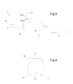
- the figure 5 schematically represents a side view of a maintenance device 1.
- the maintenance device 1 comprising a body 2 floating on the water.
- the floating body 2 is for example made in the form of a ship hull.
- Such a vessel can be monohull or multihull.
- An intervention platform 14 is provided at the rear of the maintenance device 1.
- the intervention platform 14 can extend over the entire width of the maintenance vessel and along its stern.
- the maintenance device 1 also navigates on the water through a propulsion system connected to the body.
- the propulsion system uses, for example, electrical energy or a fuel or both of these sources of energy.
- the propulsion system represented in figure 5 comprises in particular two hydrojets 5 and 6.
- the propulsion system is controlled by a control module 8 which controls the direction of the maintenance device 1 and its speed.
- the control module 8 receives, for example, a signal S36 supplied by a transmitter and receiver radio system 54.
- the radio system 54 can thus receive from the laboratory ship 35 the data representative of the general configuration in which the laboratory ship 35, the towed network of seismic streamers 4 and the maintenance device 1 as represented in FIG. figure 1 .
- the maintenance device 1 can thus be directed between two seismic streamers 4.
- the hydrojets 5 and 6 used are advantageously non-sharp for a seismic streamer 4.
- the propulsion means of the maintenance device 1 is not likely to damage a seismic streamer 4 when it evolves on the perimeter of the towed network of seismic streamers.
- the location of the seismic flute can be realized thanks to the hydroacoustic or visual localization system. by the driver of the maintenance device.
- the maintenance device 1 further comprises its own hydroacoustic or hydro-optical location system attached to the body 2.
- a hydroacoustic transmitter-receiver system 39 is shown alone in FIG. figure 6 and includes a hydroacoustic transmitter 9 and hydroacoustic receiving antennas.
- the locating transmitter-receiver system 39 can be raised or lowered in a well arranged in the hull 2 to be reassembled in the hull 2 or to be lowered under the hull 2.
- the transceiver location system 39 communicates with a beacon 11 attached to the seismic streamer 4, as shown in FIG. figure 5 .
- This beacon 11 is fixed beforehand to a seismic flute 4, for example on the seismic flute to be the subject of maintenance operations.
- the maintenance device 1 engages between the seismic flutes and approaches one of them to fix the hydroacoustic beacon 11.
- Fixing the tag can be achieved for example by one or more clamping rings. These clamping rings are for example arranged around the outer casing 91, a flexible support being interposed between the ring and the outer casing.
- the beacon includes, for example, a hydroacoustic positioning system, a satellite positioning system and a communication system with the maintenance device 1.
- the signal S12 transmitted by the location system 39 is representative of the hydroacoustic beacon relative position 11 relative to the maintenance device 1 in a three-dimensional reference. This relative position is determined by a set of transmitted data representative of the difference in longitude, the difference in latitude and the depth of the beacon 11.
- the signal S12 transmitted by the location system 39 is also representative of the relative speed of the maintenance device 1 relative to the hydroacoustic beacon 11, in a three-dimensional reference.
- This hydroacoustic beacon 11 makes it possible to improve the positioning of the maintenance device 1 with respect to the seismic streamer network and more particularly with respect to the seismic streamer 4 on which maintenance operations must be performed.
- control module 8 can control the speed of the maintenance device 1 relative to the seismic streamer 4 and be placed precisely at a distance from it.
- the control module 8 can for example set a substantially constant speed of the maintenance device 1 with respect to the seismic streamer 4 or a zero speed of the maintenance device 1 with respect to the seismic streamer 4.
- the speed of the maintenance device 1 can be set by the control module 8 automatically or semi-automatically with respect to that of the seismic streamer 4 as a function of the signal S12 supplied by the location system 39.
- the lateral deviation between the maintenance device 1 and the seismic streamer 4 can be adjusted by the control module 8 automatically or semi-automatically according to the signal S12 provided by the hydroacoustic localization system.
- the gap between the maintenance device 1 and the beacon 11 can also be adjusted by the control module 8 automatically or semi-automatically according to the signal S12 provided by the hydroacoustic localization system.
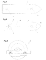
- the propulsion system disposed under the hull 2 can comprise two azimuthal hydrojets 5 and 6.
- An azimuthal hydrojet makes it possible to regulate the propulsive force but also the direction of propulsion with respect to the hull 2.
- An azimuthal hydrojet for example appears under the form of a propellant comprising a pump generating a directional propulsion water jet.
- a hydrojet 5 is disposed at the stern of the hull 2 while another hydrojet 6 is disposed at the bow of the hull 2. The adjustment of a lateral distance from the seismic streamer is thus facilitated.
- the figure 8 represents another propulsion system comprising three azimuthal hydrojets. Setting a lateral distance from the seismic streamer is also facilitated.
- the propulsion system comprises a plurality of hydrojets 5, 6 and 7 sized so that in case of failure of a hydrojet during a run performed at nominal speed of the seismic flute in the water, the maneuverability of the maintenance device 1 can be kept safe.
- the propulsion system of the figure 8 also comprises a propeller system 49 which can be stopped when maneuvers near the seismic flutes 4, the seismic flutes are not likely to be damaged by the propulsion system.
- the propulsion system also comprises a system 50 of offset at the stop of the bow of the hull 2.
- the propeller system 49 associated with a rudder makes it possible to move out of the network of seismic flutes. Propulsion by means of the propeller makes it possible to reach a higher speed for less energy consumption.
- propulsion system comprising one or more non-azimuth hydrojets.
- the maintenance device 1 can advantageously and safely be used by relatively strong sea and wind conditions, for example by a wind force of 2 to 3 Beaufort or even a wind force of 4 Beaufort or even force 5 Beaufort .
- an active stabilization system 55 can be installed in the maintenance device.
- This active anti-roll stabilization system 55 is for example of the gyroscopic type and in particular makes it possible to effectively reduce the roll movements of the maintenance device 1.
- Other stabilizing systems may optionally be used for roll stabilization.
- the active anti-roll stabilization system can be controlled by the control module 8 of the maintenance device 1.
- the maintenance device is controlled so that one of its outer lateral edges 15 along which extends an intervention platform 14, comes to L112 intervention distance of the seismic flute 4.
- the longitudinal axis A111 of the body 2 is substantially parallel to the portion of seismic streamer 4 near the maintenance device.
- the intervention platform 14 can accommodate one or more operators, one or more maintenance tools 21 or one or more lifting arms 19 each equipped with a gripper 20.
- the maintenance tool 21, as shown in FIG. figure 10 is disposed above the water and offset laterally with respect to the outer edge 15.
- the maintenance tool 21 is mounted mobile in translation relative to the shell 2.
- the maintenance tool 21 is mounted to move in translation on two rails forming part of a carriage 101, the carriage 101 itself being movable in translation relative to two rails 100 secured to the shell 2.
- the maintenance tool is thus mounted on a support 28 allowing a double translation. This double translation allows on the one hand a small footprint and on the other hand an extensive choice of positioning of the maintenance tool.
- the support 28 allows two translations oriented in a direction perpendicular to the longitudinal axis A111 of the shell 2.
- the support 28 with a double translational movement thus allows a shift over the water on one side or the other hull or arrangement above the hull 2.
- tool 21 of maintenance can be positioned in an intervention position with its receptacle disposed above the water. Once the seismic flute is positioned in the receptacle of the maintenance tool 21, the latter can be held in its position above the water, shifted further above the water, close to the working platform 14 or brought over the work platform 14.
- the maintenance tool 21 may include one or more equipment to perform one or more functions.
- the maintenance tool may for example be used for brush cleaning, fluid spray cleaning or maintenance, guiding, towing or simply holding in position.
- the lift arm 19 allows one or more movements in translation or in rotation such as a telescopic multiaxis arm.
- a gripper 20 is disposed at the end of the lifting arm 19.
- the gripper 20 which will be detailed later allows seizure of the seismic flute 4 for handling.
- the seismic flute is captured in particular at its outer sheath in a portion between two connectors.
- the gripper 20 and the lifting arm 19 thus make it possible to seize the seismic streamer underwater, to bring the seismic streamer close to the work platform or above the maintenance tool or simply to maintain the seismic streamer. seismic flute close to the maintenance device.
- the lifting arm 19, thanks to the rotational or translational movements, can arrange the gripper 20 above the water or at a determined depth under water or in the vicinity of the maintenance tool 21 or above it.
- the maintenance operations performed on a seismic flute will be detailed later.
- the intervention platform 14 extending to the rear of the body 2, it also facilitates a towing of the seismic flute 4 held by the tool 21 in its position above the intervention platform 14. The operations of towing will be detailed later.
- the figure 11 schematically represents, in side view, a seismic flute 4 drawn by the laboratory vessel 35 and entered by the maintenance device 1.
- a maintenance ship 1 navigating on the sea is seen here, but a maintenance device 1 floating on a body of water 3 can also be envisaged. of different nature.
- the maintenance device 1 connected to the seismic streamer 4 can remain at a substantially constant lateral distance from the seismic streamer 4.
- the speed of the maintenance device 1 relative to that of the seismic streamer 4 can be set to zero, but it is also possible to provide a maintenance device 1 advancing or retreating relative to the seismic streamer.
- the seismic streamer 4 can thus move forward or backward with respect to the maintenance device 1 at a determined speed.
- the figure 12 is a rear perspective view of a maintenance device 1.
- the maintenance device 1 is in the form of a maintenance vessel.
- the vessel is for example of length between 30m and 60m and for example about 40m.
- the maintenance vessel has for example a draft of between 2.5m and 4.5m and for example about 3m.
- the maintenance device 1 comprises a platform 14 disposed at the rear of the shell 2, that is to say along the stern and extending from one edge to the other of the shell 2.
- maintenance 21 is fixed on a support 28 with double translation extending along the bow.
- the support 28 of the maintenance tool extends for example over the entire width of the intervention platform 14. In the case of a monohull maintenance vessel, the support 28 extends for example from the port edge to the edge starboard. Thanks in particular to the double translation, the maintenance tool can be brought to the port or starboard of the maintenance device 1.
- winches 47 are arranged side by side on the intervention platform 14, vis-à-vis the support 28 with double translation, their axis being perpendicular to the longitudinal axis of the hull 2.
- the two winches 47 are arranged in front of the support 28 of the maintenance tool.
- Each winch 47 has for example a traction capacity of between 3 tons and 10 tons, for example 5 tons.
- the maintenance tool 21 can be positioned in front of one or other of the winches 47, to allow the change or the storage of one or more sections of seismic flute.
- lifting arms 19 each carrying a gripper at their end.
- the lifting arms 19 are arranged in front of the support 28 of the maintenance tool 21.
- a lifting arm 19 is placed on the port side while the other lifting arm 19 is positioned on the starboard side so as to intervene on both edges. lateral of the intervention platform 14.
- the lifting arm 19 is arranged on the intervention platform 14 at a determined distance from the outer edge and at a determined distance from the support 28 of the maintenance tool 21.
- Each lifting arm 19 is for example disposed about 1 m from the side edge of the maintenance device and at a distance between 5m and 8m of the support 28 of the maintenance tool 21.
- Each lifting arm 19 has for example a mass of between 2000kg and 5000kg and for example about 3500kg.
- the grippers are for example made of steel, aluminum or composite material and each have a mass of between 200kg and 500kg, for example about 300kg.
- Each lifting arm can for example develop a torque around a vertical axis of about 40000N / m and a load torque of about 40t / m.
- the lifting arms 19, extended to the maximum, are for example sized to be able to lift a mass of about 4000kg.
- the maintenance tool 21 may in particular be offset relative to a lateral edge of the intervention platform 14 so as to be positioned above the water on the port or starboard side of the hull 2, in order to cooperate with one or the other of the grippers.
- Two workspaces 16 for one or more operators are arranged along each of the lateral edges of the platform 14 of intervention. These workspaces 16 are each disposed between a lifting arm 19 and the support 28 of the maintenance tool. A central working area behind the winches 47 is arranged between these two lateral working spaces 16.
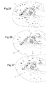
- the Figures 13 to 17 represent different positions of the gripper installed at the end of the lifting arm 19.
- the gripper 20 comprises a leg 31 extending over a predetermined length, in particular so as to be able to seize the seismic streamer under water, if necessary.
- the leg has for example a length of between 50cm and 2m.
- the length of the leg 31 is chosen according to the type of seismic flute to be grasped.
- the leg 31 is positioned and oriented by the multiaxis lift arm 19. This leg 19 may in particular be inclined around a horizontal axis as shown in FIG. figure 16 or rotated around a vertical axis as shown in figure 17 .
- the leg 31 is further connected to an L-shaped portion to form a receptacle.
- the L-shaped portion consists of a portion 32 intended to support the seismic flute 4 and a portion 33 intended to laterally retain the seismic flute 4.
- the seismic flute 4 is also maintained laterally opposite the portion 33 , by the lower end of the leg 31.
- the L-shaped portion is retracted by pivoting relative to the leg 31.
- An actuator is arranged in the leg 31 to return the portion L with its support portion 32 perpendicular to the leg 31. This actuator can be controlled automatically for a retraction of the portion L.
- the gripper 20 may also comprise a finger 34 for movable support between a retracted position in the leg 31 and a folded position over the L-shaped portion.
- An actuator is also arranged in the leg to lower the finger 34 or to raise it in position.
- the finger 34 can exert a determined force making it possible to maintain the seismic flute without preventing a sliding thereof in the receptacle of the gripper 20.
- the finger 34 and the receptacle of the gripper 20 comprise for example non-rough contact surfaces intended to come against the seismic flute.
- the Figures 18 and 19 show the holding tool performing a cleaning of a seismic streamer 4.
- the holding tool 21 comprises a receptacle consisting of a support portion 22 intended to support the seismic streamer 4 and portions 23 and 30 of lateral guide of the seismic flute 4.
- the support portion 22 is intended to be arranged substantially horizontally.
- the receptacle thus has a U-shaped profile.
- One of the lateral guide portions 23 or 30 is provided to be retracted outwards in the event of excessive force applied by the maintenance tool on the seismic streamer.
- This maximum limit force is calculated as a function of the resistance, of all the elements constituting the maintenance device and as a function of the resistance of the seismic streamer 4.
- the outer guiding portion can be retracted automatically for safety.
- One can also provide a retraction actuated by an actuator.
- the receptacle of the maintenance tool may be equipped with one or more mechanical systems each performing a function.
- a cleaning system comprises brushes 25.
- the brushes 25 are in the form of rollers disposed on either side of the seismic streamer.
- the brushes 25 may be rotatable or fixed relative to the receptacle.
- a brush is for example arranged in a lateral guide portion 23 or 30 or in the support portion 22 or on an edge of one of these portions 22, 23 or 30.
- a single brush or a plurality of brushes may be connected to the receptacle of the maintenance tool.
- Each brush 25 thus acts all along the seismic streamer while the latter slides in the receptacle of the maintenance tool.
- the sliding of the seismic flute in the maintenance tool is due to the displacement of the maintenance device with respect to the seismic flute.
- the maintenance device may move forward or backward from the seismic streamer to slide the seismic streamer in either direction. Rotating brushes relative to the receptacle make it possible to increase the effect of brushing.
- the maintenance tool may also include a system 27 for spraying the seismic streamer 4 with jets 102, as shown in FIG. figure 19 .
- the spraying system comprises nozzles 27 fixed to the receptacle and oriented towards the interior of the receptacle for spraying a jet of cleaning fluid onto the seismic streamer 4.
- the nozzles of the spraying system can be arranged on either side of the seismic streamer, in the lateral guide portions and above the passage for the seismic streamer.
- a cleaning jet 102 is for example in the form of a jet of pressurized liquid such as water.
- the water is for example brought to a pressure of several bars or several tens of bars.
- the pumping and storage systems of the cleaning fluid are conventional systems and are not shown. Their control can be carried out by the control module 8 or by the operators on the intervention platform.
- the nozzles can also spray a coating of specific composition for protection of the seismic flute against fouling.
- the seismic flute sliding in the receptacle is thus coated on its entire outer periphery and all along the seismic streamer.
- the maintenance tool can perform cleaning by brushes or a sprinkler system or a combination of brushes and sprinkler system.
- the maintenance tool can also be used for towing, as illustrated by the Figures 20 and 21 .
- the figure 20 shows a seismic flute 4 equipped with a stop 103 disposed in front of the maintenance tool 21.
- This stop 103 comprises two half-stops 103a and 103b assembled together and fixed around a half-connector.
- the connector can thus be disassembled without detaching this stop 103.
- the abutment is thus integral with one of the seismic flute sections joined together by the connector 90.
- the half-stops 103a and 103b comprise fastening means such as tabs 104 screwed together to fix the half-stops between them. Other means for fixing the half stops may be envisaged.
- the inner housing of the abutment 103 clamped around a half-connector may comprise a rough surface, teeth or ribs for securing.
- the stop 103 has a flared and curved outer profile intended to lock in the receptacle of the maintenance tool. Thus the seismic flute can move back into the receptacle of the maintenance tool until the stop comes to bear against the receptacle.
- the abutment 103 has for example rounded concave side walls cooperating with the rounded convex walls of the receptacle.
- the seismic streamer When the abutment bears against the receptacle, the seismic streamer is pulled by the maintenance tool. The seismic flute then retains the possibility of being pulled forward, because of the shape of the stop.
- the connector 90 can be disassembled by an operator.
- the figure 21 represents a stop 103 pulled by the maintenance tool, a rear portion of the seismic streamer 4 itself being integral with the stop 103. It is then possible to fix a new seismic streamer section from a winch.
- the stop can be advanced relative to the maintenance tool by operating the winch.
- the seismic flute is then towed by the winch and the stop can be disassembled.
- the winch can be wound for the storage of a seismic flute section or the winch can be unwound for the provision of a new section of seismic flute.
- the stop 103 can be secured again on a connector before being locked again in the maintenance tool.
- the connector can then be disassembled to detach the section connected to the winch.
- the remaining section upstream tracked by the laboratory vessel can then be entered to be attached to the section pulled by the maintenance tool.
- the outer profile of the stop 103 advantageously makes it possible not to block the seismic streamer when the stop is fixed on the seismic streamer while it is pulled by the laboratory ship and passes into the receptacle of the maintenance tool. Indeed, in the event of slowing down of the maintenance device, the seismic streamer is free to advance into the receptacle of the maintenance tool and, in case of acceleration of the maintenance device, the portion of the seismic streamer upstream of the stop is towed by the laboratory vessel while the downstream portion of the stop is towed by the maintenance tool.
- the walls 22, 23 and 30 of the receptacle are curved towards the interior of the receptacle thus creating a narrowing in the receptacle passage.
- the section of the passage is narrowed laterally and vertically.
- the curved V-shaped outer profile abutment can thus be wedged in the passage at the front of the receptacle 21.
- the stop 103 comprises a front portion whose diameter corresponds to the maximum diameter of the abutment. This front portion of the stop is intended to remain outside the passageway in the receptacle of the maintenance tool, as shown in FIG. figure 21 .
- the figure 22 represents the maintenance device 1 when seizing a seismic streamer.
- the seismic flute 4 can be heard under shallow water, or on the surface of the water.
- the seismic flute is for example located under water at a depth of 1m.
- the gripper 20 is immersed vertically in the water then its leg is brought against the seismic flute 4 before raising the gripper 20 so that the line is maintained in the receptacle of the gripper on its support portion.
- the lifting arm 19 of the gripper 20 is controlled automatically, semi automatically or manually.
- the lifting arm 19 extends for example over a distance to access a seismic streamer located 3m from the maintenance device 1 and 1m underwater.
- the lifting arm 19 is disposed on the shell 2 so as to be able to immerse the gripper 20 under water vertically and at a distance from the shell.
- the lifting arm 19 is installed at the edge of the intervention platform 14 as previously described.
- the maintenance device 1 For gripping the seismic streamer the maintenance device 1 is positioned at a distance less than or equal to an approach distance to be able to perform this gripping.
- the seismic flute 4 can then be lifted by the lifting arm and the gripper, as shown in FIG. figure 23 .
- the lifting arm 19 is of course designed to be able to lift the seismic streamer 4. Furthermore, the lifting arm is sufficiently extended to lift the seismic streamer at a height of between 0 and 5 m above the water and for example about 4m.
- the seismic streamer 4 is disposed in the receptacle of the maintenance tool 21 for intervention on the seismic streamer.
- the maintenance tool and the gripper can be used successively or simultaneously.
- the receptacle and the gripper are movable relative to each other at least in a direction transverse to the maintenance device.
- This transverse direction is here substantially perpendicular to the longitudinal axis of the floating body of the maintenance device.
- the longitudinal axis of the floating body is substantially oriented in the same direction as the seismic flute which extends along floating body.
- the receptacle of the maintenance tool 21 is mounted to move relative to the intervention platform 14.
- the support 28 of the maintenance tool extends transversely to the longitudinal axis of the shell and allows a double translation, as previously described.
- the maintenance tool can be arranged in the middle of the maintenance platform as shown in FIG. figure 23 or in a staggered position above the water as shown in figure 24 .
- Other positions above the intervention platform 14 may of course be set.
- the offset or alignment between the receptacle of the maintenance tool and the receptacle of the gripper can also be adjusted.
- the maintenance tool 21 can be shifted transversely in alignment with the seismic streamer 4 held in the gripper 20, as shown in FIG. the figure 24 .
- the receptacles of the gripper 20 and the maintenance tool 21 are then offset relative to an outer lateral edge of the shell and are arranged in the same longitudinal plane.
- the support 28 of the maintenance tool is sized to offset the tool relative to the outer edge at a distance between 0m and 3m and for example about 2m.
- the support 28 is also dimensioned so that the maintenance tool 21 fixed on the support 28 is disposed above the water level at a height of between 1m and 3m and for example about 1.5m.
- the gripper may be disposed at a level higher than that of the receptacle of the maintenance tool 21 and the seismic streamer 4 may then be deposited in the receptacle of the maintenance tool 21 by lowering the gripper 20.
- the lifting arm 19 of the gripper extends for example radially over a distance of between 6m and 10m and by example of about 8m to be able to come close to the maintenance tool and at a level above it.
- the lifting arm 19 can deposit the seismic streamer 4 in the receptacle of the maintenance tool 21 or, conversely, lift the seismic streamer out of the tool 21.
- the figure 25 represents the maintenance device 1 comprising its maintenance tool 21 disposed in a position offset above the water and also receiving the seismic streamer 4.
- the seismic streamer 4 is also held by the gripper 20 which is disposed at a predetermined distance in front of the maintenance tool and in alignment.
- the gripper 20 and the maintenance tool 21 are therefore at the same height.
- the seismic flute is disposed in an intervention zone Z29 opposite a working zone 16 of the intervention platform 14.
- the intervention zone Z29 is, for example, at most 1m from the zone 16.
- This working area 16 can accommodate one or more operators 18.
- this work area is secured by a guardrail along the edge vis-à-vis the intervention zone Z29.
- a guardrail 17 also borders a central work area of the intervention platform.
- a slight pressure for maintaining the seismic streamer in the gripper can be provided by means of the locking finger described above. This locking ensures the guidance of the flute in the gripper 20 without exerting force on the seismic flute 4 in a longitudinal direction of the flute.
- the maintenance device can advance at the same speed as the seismic flute which is then stationary relative to the working zone 16.
- control of the maintenance device 1 does not respect the maximum forces provided by the maintenance tool and the gripper on the seismic streamer, it can be released by retraction of the L-shaped portion of the gripper 20 and by retraction of the outer guide portion 30 of the maintenance tool 21.
- the retraction can be triggered automatically or by the operators 28.
- the maintenance operations are for example the cleaning of the seismic flute, the repair or replacement of the control and guiding units 37 or the repair or replacement of other elements fixed to the seismic flute. It is also possible in this area of intervention Z29 operations for the replacement of a damaged section of seismic flute.
- the maintenance device according to the invention thus allows a gain in productivity and safety and moreover it is possible to intervene in a wider range of weather conditions.
- the working comfort and the safety of the operators are optimized and improved.
- the operators 28 can easily position tools required for maintenance near the seismic streamer.
- the control device of the propulsion system may also allow the navigating officer to precisely adjust the position of the maintenance device 1 so that the maintenance device 1 moves parallel and at the same speed as the seismic streamer 4
- the maintenance device is, for example, positioned automatically with an accuracy of less than 1m.
- the locking finger of the gripper 20 is retracted.
- the lift arm 19 can then lift the gripper to lift the seismic streamer out of the maintenance tool 21 before returning it to the water.
- the gripper 20 is disengaged laterally from the immersed seismic flute 4.
- the figure 26 represents the maintenance device 1 with its maintenance tool 21 receiving the seismic streamer 4 which slides relative to the receptacle of the maintenance tool 21.
- the seismic streamer has been deposited in the maintenance tool 21 by the gripper 20, then the latter was brought above the platform 14, in the storage position.
- the lifting arm 19 is for example in a storage position with its gripper 20 above of the intervention platform 14.
- the maintenance tool 21 is connected to the intervention platform by its support 28 with double translation.
- the maintenance tool 21 is thus driven by the maintenance device 1 which navigates next to the seismic streamer 4.
- the maintenance tool 21 also remains fixedly held relative to the body of the maintenance device in its maintenance position. above water.
- the control device of the propulsion system may also allow the navigating officer to adjust the position of the maintenance device 1 so that the maintenance device 1 moves parallel and a constant speed with respect to the seismic streamer 4
- the speed difference corresponds to the speed at which the seismic streamer 4 slides in the receptacle.
- the maintenance tool can therefore be applied along the seismic streamer 4.
- the seismic streamer can thus be cleaned or coated by the maintenance tool 21.
- the seismic streamer 4 can be raised temporarily by the gripper 20, as explained in connection with the figure 24 .
- the integral element of the seismic streamer passes over the maintenance tool 21.
- the quick, sse of the maintenance device can be reduced momentarily.
- the seismic flute 4 is then rested in the receptacle of the maintenance tool 21 to be treated on a new length between two elements integral with the seismic streamer 4 such as the control and guiding units 37.
- the gripper can lift the seismic streamer out of the maintenance tool 21 before submitting it back into the water. Finally the gripper is released laterally from the immersed seismic flute.
- the figure 27 represents the maintenance device pulling a seismic flute portion.
- the position of the maintenance device 1 along the flute is adjusted so as to bring a junction element 90 of two sections of the seismic streamer up to the area 16 of work of the operators, as represented at figure 25 .
- the operators can arrange the clamping jaw with a stop as described in Figures 20 and 21 around the junction connector 90 of the seismic streamer at the head of a defective section.
- the maintenance device 1 can then advance a few meters along the seismic streamer 4 so that this stop comes against the receptacle of the maintenance tool 21. It is then the maintenance tool that tows the downstream part of the seismic flute 4 while the tension on the upstream part is released.
- the upstream part of the seismic streamer can then be separated from the downstream part.
- a buoy can be attached to the upstream part before detachment to facilitate its recovery.
- the free upstream portion along the maintenance device is towed by the laboratory vessel.
- the upstream part can also be maintained in the gripper 20 by means of its locking finger.
- the downstream part of the seismic streamer which extends behind the maintenance device 1 is on the other hand towed by the maintenance device 1.
- the seismic streamer section engaged in the maintenance tool 21 is here a defective section whose replacement is necessary.
- the support 28 is controlled to bring the maintenance tool 21 in a position above the intervention platform 14 to facilitate the connection operations of the seismic flute portion with one of the storage winches 47.
- a cable or a seismic streamer previously wound on the winch 47 is then used to connect the seismic streamer held in the maintenance tool 21.
- the faulty downstream seismic flute section is wound on the storage winch 47.
- the winch 47 is first wound up slightly to advance the stop 103 relative to the maintenance tool 21. The stop is then disengaged from the connector 90 and the defective section can be wound completely around the winch 47.
- a stop 103 is then again attached to a connector 90 connecting the seismic flute portion downstream of the defective section.
- the winch 47 for storing the defective section is then unwound in order to position the stop 103 against the maintenance tool 21. It is then the maintenance tool 21 which tows the downstream part of the seismic streamer 4 while the tension on the upstream part slackens.
- the connector can then be detached from the defective section.
- a replacement flute section was previously stored on a second winch 47. This seismic flute section is then connected to the seismic flute portion towed by the maintenance tool 21.
- the second winch is slightly wound to advance the stop 103 so as to separate it from the connector, then the second winch is unrolled.
- the second winch 47 for storing the replacement section is then unwound in order to position the abutment 103 against the maintenance tool 21. It is then the maintenance tool 21 which tows the downstream part of the seismic flute 4 while the tension on the upstream part relaxes.
- the connector can then be detached from the section connected to the second winch 47.
- the upstream flute portion towed by the laboratory vessel is then attached to the newly installed flute portion.
- the maintenance tool 21 is again arranged along the edge of the work platform.
- the speed of the maintenance device 1 is slowed down so as to allow the upstream portion of the seismic streamer to take up the voltage on the downstream part.
- the stop is then disengaged from its connector.
- the gripper can lift the seismic streamer 4 out of the maintenance tool 21 before submitting it back into the water. Finally, the gripper 20 is released laterally from the submerged seismic streamer.
- the support 28 arranged along the bow of the hull 2 facilitates the towing of the seismic streamer behind the maintenance device 1. In fact, nothing hinders the positioning of the seismic streamer from the offset position to an edge towards the central position above the intervention platform. In addition, the movements of the seismic flute towed by the maintenance device are not hindered.
- the figure 28 shows an example of a control module 8 comprising communication interfaces 58-65 connected by a communication bus with a computer 73 and a memory component 82.
- the bus notably performs data transfer functions but also component control or control functions. addressing the data.
- the control member comprises of course a supply member and a timing clock not shown.
- the figure 29 is a graphical representation of the location data S36 transmitted by the transmitting and receiving radio system 54 in association with the laboratory ship.
- This radio system 54 is connected to a communication interface 58 of the control module 8, the received data S36 being managed by a location data management program P76 to be stored in a memory space D74.
- These data D74 comprise, for example, the positioning in a reference mark of at least two dimensions or even three dimensions of the laboratory vessel 35, the floats 38, the control and guiding units 37, the seismic streamer network, and the positioning of the device. maintenance 1.
- the figure 30 is a graphical representation of the data S12 localization provided by the system 39 for locating the maintenance device, this system 39 being connected to a communication interface 59 of the control module 8.
- These data S12 are managed by a location data management program P76 and stored in a D75 memory space.
- These data D75 comprise for example the positioning in a reference mark at least two or even three dimensions of the maintenance device 1 with respect to the beacon 11 attached to a seismic streamer 4 as well as the speed V1 of the maintenance device 1 relative to this tag 11.
- These different location data D74 and D75 are for example processed by a program P110 pretreatment of location data which compiles for example to superimpose the two location marks.
- the superposition of the location data is stored by this program P110 in a memory space D77 in the form of compiled location data D77.
- These compiled localization data are in particular represented at figure 31 .
- the location data D74, D75 or D77 can be transmitted, via a communication interface 65, to a display screen 66.
- the navigating officer can view the location data received by radio link and from the laboratory ship or the location data generated by its own hydroacoustic location system or compiled location data.
- the location data of the maintenance device is displayed in the form of an image 67 on the screen 66.
- the choice of the display of one or the other of the location data can be performed by selection buttons. Each associated with a display of a determined type of data among the different location data.
- the location data from the laboratory vessel and / or the location data generated by the hydroacoustic location system 39 and / or location data compiling both types of data can be used for positioning control.
- automatic or semi-automatic maintenance device The navigating officer thus has an automated tool for controlling his position.
- the control device is controlled by a man-machine interface comprising steering rod controls 69 connected to a communication interface 64 of the control module 8 and propulsion commands 70 connected to a communication interface 63 of the control module 8
- a setpoint management program P80 manages these last two communication interfaces 63 and 64 to generate stored data D81 for controlling the propulsion system.
- This control data D81 is transmitted, via a communication interface 60, in the form of a control signal C57 to a power module 56 generating a command for the propulsion system.
- the navigating officer also has, on his operator terminal, various control buttons 71 and one or more control knobs 72.
- the signals received by these interfaces are stored by an instruction management program in the form of data D83 and D84.
- These data D83 and D84 are processed by the instruction management program P85 on the one hand to modify the on-screen display data D77.
- the D84 commands entered on the operator terminal appear in a command line 68, as well as the calculation results resulting from the execution of this command.
- the data D83 generated by a cursor 72 may allow the display of a cursor but also allow the generation of registration operation on the displayed plan and calculation whose result is then displayed on the screen.
- the instruction management program P85 can modify the positioning control data D81 of the maintenance device 1.
- the maintenance device can be accurately controlled manually, semi automatically or automatically.
Landscapes
- Chemical & Material Sciences (AREA)
- Engineering & Computer Science (AREA)
- Combustion & Propulsion (AREA)
- Mechanical Engineering (AREA)
- Ocean & Marine Engineering (AREA)
- Earth Drilling (AREA)
- Buildings Adapted To Withstand Abnormal External Influences (AREA)
Applications Claiming Priority (1)
| Application Number | Priority Date | Filing Date | Title |
|---|---|---|---|
| FR1302676A FR3013314B1 (fr) | 2013-11-20 | 2013-11-20 | Dispositif de maintenance et de reperage d'une flute sismique |
Publications (1)
| Publication Number | Publication Date |
|---|---|
| EP2876037A1 true EP2876037A1 (de) | 2015-05-27 |
Family
ID=50137707
Family Applications (1)
| Application Number | Title | Priority Date | Filing Date |
|---|---|---|---|
| EP14290334.3A Withdrawn EP2876037A1 (de) | 2013-11-20 | 2014-11-07 | Wartungs- und Ortungsvorrichtung eines Schleppsonars |
Country Status (2)
| Country | Link |
|---|---|
| EP (1) | EP2876037A1 (de) |
| FR (1) | FR3013314B1 (de) |
Cited By (1)
| Publication number | Priority date | Publication date | Assignee | Title |
|---|---|---|---|---|
| CN110525616A (zh) * | 2019-09-17 | 2019-12-03 | 哈尔滨工程大学 | 基于浮力调节的海底地震检波飞行节点航行器及工作方法 |
Families Citing this family (1)
| Publication number | Priority date | Publication date | Assignee | Title |
|---|---|---|---|---|
| CN111069102A (zh) * | 2019-12-03 | 2020-04-28 | 广州市丹爵通讯科技有限公司 | 一种用于海上救援的应急无线通讯设备 |
Citations (4)
| Publication number | Priority date | Publication date | Assignee | Title |
|---|---|---|---|---|
| GB2321665A (en) | 1997-01-31 | 1998-08-05 | Western Atlas Int Inc | Seismic cables |
| GB2488635A (en) * | 2011-03-02 | 2012-09-05 | Pgs Geophysical As | Self propelled cleaning device for marine streamers |
| US20130098394A1 (en) * | 2011-10-19 | 2013-04-25 | Pgs Geophysical As | Tools and methods for cleaning survey cables |
| US20130265850A1 (en) * | 2012-04-05 | 2013-10-10 | Cggveritas Services Sa | Active cleaning device for seismic streamers and related methods |
-
2013
- 2013-11-20 FR FR1302676A patent/FR3013314B1/fr active Active
-
2014
- 2014-11-07 EP EP14290334.3A patent/EP2876037A1/de not_active Withdrawn
Patent Citations (4)
| Publication number | Priority date | Publication date | Assignee | Title |
|---|---|---|---|---|
| GB2321665A (en) | 1997-01-31 | 1998-08-05 | Western Atlas Int Inc | Seismic cables |
| GB2488635A (en) * | 2011-03-02 | 2012-09-05 | Pgs Geophysical As | Self propelled cleaning device for marine streamers |
| US20130098394A1 (en) * | 2011-10-19 | 2013-04-25 | Pgs Geophysical As | Tools and methods for cleaning survey cables |
| US20130265850A1 (en) * | 2012-04-05 | 2013-10-10 | Cggveritas Services Sa | Active cleaning device for seismic streamers and related methods |
Non-Patent Citations (1)
| Title |
|---|
| KEITH VICKERY ET AL: "DYNAMIC POSITIONING CONFERENCE ACOUSTIC POSITIONING SYSTEMS "A PRACTICAL OVERVIEW OF CURRENT SYSTEMS" Session Index Keith Vickery Sensors Acoustic Positioning Systems ACOUSTIC POSITIONING SYSTEMS "A PRACTICAL OVERVIEW OF CURRENT SYSTEMS"", 14 October 1998 (1998-10-14), XP055133336, Retrieved from the Internet <URL:http://www.dynamic-positioning.com/dp1998/svickery.pdf> [retrieved on 20140805] * |
Cited By (1)
| Publication number | Priority date | Publication date | Assignee | Title |
|---|---|---|---|---|
| CN110525616A (zh) * | 2019-09-17 | 2019-12-03 | 哈尔滨工程大学 | 基于浮力调节的海底地震检波飞行节点航行器及工作方法 |
Also Published As
| Publication number | Publication date |
|---|---|
| FR3013314B1 (fr) | 2018-02-09 |
| FR3013314A1 (fr) | 2015-05-22 |
Similar Documents
| Publication | Publication Date | Title |
|---|---|---|
| EP3292040B1 (de) | Unterwasserfahrzeug zur inspektion einer unterwasserstruktur in einem gewässer und zugehöriges verfahren | |
| Trslic et al. | Vision based autonomous docking for work class ROVs | |
| US20110197919A1 (en) | Barnacle Fouling Tool | |
| EP3257738B1 (de) | Verfahren zur installation eines unterwasserkabels | |
| EP2965128B1 (de) | Autonome reinigungsvorrichtung für seismische streamer | |
| US20170031046A1 (en) | Overboard system for deployment and retrieval of autonomous seismic nodes | |
| EP3784558B1 (de) | System zur einsetzen und zurückholen einer autonomen unterwasservorrichtung, verfahren zur verwendung | |
| US20220033042A1 (en) | A marine structure comprising a launch and recovery system | |
| FR2704250A1 (fr) | Procédé et dispositif de pose et d'ensouillage en continu d'une conduite flexible sous-marine. | |
| NO347397B1 (en) | Intermediate docking station for underwater vehicles | |
| KR20180094608A (ko) | 수상선 기반의 수중로봇 시스템 | |
| EP2876037A1 (de) | Wartungs- und Ortungsvorrichtung eines Schleppsonars | |
| KR20220006573A (ko) | 선체의 수중 모니터링 및 유지관리용 로봇, 시스템 및 방법 | |
| EP2876038A1 (de) | Wartungsvorrichtung zur Reinigung eines Schleppsonars | |
| US20240025523A1 (en) | Underwater snake robot with passive joints | |
| US10583897B2 (en) | High angle deployment system for a seismic marine surface vessel | |
| EP2876034A1 (de) | Zuggerät für eine Wartungsvorrichtung eines Schleppsonars | |
| FR3087748A1 (fr) | Deploiement et levage de charges a l'aide d'un vehicule sous-marin | |
| JP2004166434A (ja) | 海底布設長尺体防護管の被着方法および装置 | |
| FR3055607A1 (fr) | Systeme de communication et de transfert entre un objet emerge et un objet immerge, ensemble comprenant un objet emerge, un objet immerge et procede de mise en communication et transfert entre l'objet | |
| Stangeland | Subsea standalone vehicle system for Snorre | |
| O'Halloran et al. | AUVs and ROVs: Supporting Offshore Renewable Technologies | |
| OA19636A (en) | Underwater vehicle for inspection of a subsea structure in a body of water and related method. |
Legal Events
| Date | Code | Title | Description |
|---|---|---|---|
| PUAI | Public reference made under article 153(3) epc to a published international application that has entered the european phase |
Free format text: ORIGINAL CODE: 0009012 |
|
| 17P | Request for examination filed |
Effective date: 20141107 |
|
| AK | Designated contracting states |
Kind code of ref document: A1 Designated state(s): AL AT BE BG CH CY CZ DE DK EE ES FI FR GB GR HR HU IE IS IT LI LT LU LV MC MK MT NL NO PL PT RO RS SE SI SK SM TR |
|
| AX | Request for extension of the european patent |
Extension state: BA ME |
|
| STAA | Information on the status of an ep patent application or granted ep patent |
Free format text: STATUS: THE APPLICATION HAS BEEN WITHDRAWN |
|
| 18W | Application withdrawn |
Effective date: 20151006 |