EP2875862A1 - Catalyst for cleaning exhaust gas - Google Patents
Catalyst for cleaning exhaust gas Download PDFInfo
- Publication number
- EP2875862A1 EP2875862A1 EP13856424.0A EP13856424A EP2875862A1 EP 2875862 A1 EP2875862 A1 EP 2875862A1 EP 13856424 A EP13856424 A EP 13856424A EP 2875862 A1 EP2875862 A1 EP 2875862A1
- Authority
- EP
- European Patent Office
- Prior art keywords
- catalyst
- exhaust gas
- region
- end surface
- catalyst layer
- Prior art date
- Legal status (The legal status is an assumption and is not a legal conclusion. Google has not performed a legal analysis and makes no representation as to the accuracy of the status listed.)
- Granted
Links
Images








Classifications
-
- B—PERFORMING OPERATIONS; TRANSPORTING
- B01—PHYSICAL OR CHEMICAL PROCESSES OR APPARATUS IN GENERAL
- B01D—SEPARATION
- B01D53/00—Separation of gases or vapours; Recovering vapours of volatile solvents from gases; Chemical or biological purification of waste gases, e.g. engine exhaust gases, smoke, fumes, flue gases, aerosols
- B01D53/34—Chemical or biological purification of waste gases
- B01D53/92—Chemical or biological purification of waste gases of engine exhaust gases
- B01D53/94—Chemical or biological purification of waste gases of engine exhaust gases by catalytic processes
- B01D53/9445—Simultaneously removing carbon monoxide, hydrocarbons or nitrogen oxides making use of three-way catalysts [TWC] or four-way-catalysts [FWC]
- B01D53/9454—Simultaneously removing carbon monoxide, hydrocarbons or nitrogen oxides making use of three-way catalysts [TWC] or four-way-catalysts [FWC] characterised by a specific device
-
- B—PERFORMING OPERATIONS; TRANSPORTING
- B01—PHYSICAL OR CHEMICAL PROCESSES OR APPARATUS IN GENERAL
- B01D—SEPARATION
- B01D53/00—Separation of gases or vapours; Recovering vapours of volatile solvents from gases; Chemical or biological purification of waste gases, e.g. engine exhaust gases, smoke, fumes, flue gases, aerosols
- B01D53/34—Chemical or biological purification of waste gases
- B01D53/74—General processes for purification of waste gases; Apparatus or devices specially adapted therefor
- B01D53/86—Catalytic processes
-
- B—PERFORMING OPERATIONS; TRANSPORTING
- B01—PHYSICAL OR CHEMICAL PROCESSES OR APPARATUS IN GENERAL
- B01J—CHEMICAL OR PHYSICAL PROCESSES, e.g. CATALYSIS OR COLLOID CHEMISTRY; THEIR RELEVANT APPARATUS
- B01J23/00—Catalysts comprising metals or metal oxides or hydroxides, not provided for in group B01J21/00
- B01J23/38—Catalysts comprising metals or metal oxides or hydroxides, not provided for in group B01J21/00 of noble metals
- B01J23/54—Catalysts comprising metals or metal oxides or hydroxides, not provided for in group B01J21/00 of noble metals combined with metals, oxides or hydroxides provided for in groups B01J23/02 - B01J23/36
- B01J23/56—Platinum group metals
- B01J23/63—Platinum group metals with rare earths or actinides
-
- B—PERFORMING OPERATIONS; TRANSPORTING
- B01—PHYSICAL OR CHEMICAL PROCESSES OR APPARATUS IN GENERAL
- B01J—CHEMICAL OR PHYSICAL PROCESSES, e.g. CATALYSIS OR COLLOID CHEMISTRY; THEIR RELEVANT APPARATUS
- B01J35/00—Catalysts, in general, characterised by their form or physical properties
- B01J35/19—Catalysts containing parts with different compositions
-
- B—PERFORMING OPERATIONS; TRANSPORTING
- B01—PHYSICAL OR CHEMICAL PROCESSES OR APPARATUS IN GENERAL
- B01J—CHEMICAL OR PHYSICAL PROCESSES, e.g. CATALYSIS OR COLLOID CHEMISTRY; THEIR RELEVANT APPARATUS
- B01J37/00—Processes, in general, for preparing catalysts; Processes, in general, for activation of catalysts
- B01J37/02—Impregnation, coating or precipitation
- B01J37/024—Multiple impregnation or coating
- B01J37/0244—Coatings comprising several layers
-
- F—MECHANICAL ENGINEERING; LIGHTING; HEATING; WEAPONS; BLASTING
- F01—MACHINES OR ENGINES IN GENERAL; ENGINE PLANTS IN GENERAL; STEAM ENGINES
- F01N—GAS-FLOW SILENCERS OR EXHAUST APPARATUS FOR MACHINES OR ENGINES IN GENERAL; GAS-FLOW SILENCERS OR EXHAUST APPARATUS FOR INTERNAL-COMBUSTION ENGINES
- F01N3/00—Exhaust or silencing apparatus having means for purifying, rendering innocuous, or otherwise treating exhaust
- F01N3/02—Exhaust or silencing apparatus having means for purifying, rendering innocuous, or otherwise treating exhaust for cooling, or for removing solid constituents of, exhaust
- F01N3/021—Exhaust or silencing apparatus having means for purifying, rendering innocuous, or otherwise treating exhaust for cooling, or for removing solid constituents of, exhaust by means of filters
- F01N3/023—Exhaust or silencing apparatus having means for purifying, rendering innocuous, or otherwise treating exhaust for cooling, or for removing solid constituents of, exhaust by means of filters using means for regenerating the filters, e.g. by burning trapped particles
-
- F—MECHANICAL ENGINEERING; LIGHTING; HEATING; WEAPONS; BLASTING
- F01—MACHINES OR ENGINES IN GENERAL; ENGINE PLANTS IN GENERAL; STEAM ENGINES
- F01N—GAS-FLOW SILENCERS OR EXHAUST APPARATUS FOR MACHINES OR ENGINES IN GENERAL; GAS-FLOW SILENCERS OR EXHAUST APPARATUS FOR INTERNAL-COMBUSTION ENGINES
- F01N3/00—Exhaust or silencing apparatus having means for purifying, rendering innocuous, or otherwise treating exhaust
- F01N3/02—Exhaust or silencing apparatus having means for purifying, rendering innocuous, or otherwise treating exhaust for cooling, or for removing solid constituents of, exhaust
- F01N3/021—Exhaust or silencing apparatus having means for purifying, rendering innocuous, or otherwise treating exhaust for cooling, or for removing solid constituents of, exhaust by means of filters
- F01N3/033—Exhaust or silencing apparatus having means for purifying, rendering innocuous, or otherwise treating exhaust for cooling, or for removing solid constituents of, exhaust by means of filters in combination with other devices
- F01N3/035—Exhaust or silencing apparatus having means for purifying, rendering innocuous, or otherwise treating exhaust for cooling, or for removing solid constituents of, exhaust by means of filters in combination with other devices with catalytic reactors
-
- F—MECHANICAL ENGINEERING; LIGHTING; HEATING; WEAPONS; BLASTING
- F01—MACHINES OR ENGINES IN GENERAL; ENGINE PLANTS IN GENERAL; STEAM ENGINES
- F01N—GAS-FLOW SILENCERS OR EXHAUST APPARATUS FOR MACHINES OR ENGINES IN GENERAL; GAS-FLOW SILENCERS OR EXHAUST APPARATUS FOR INTERNAL-COMBUSTION ENGINES
- F01N3/00—Exhaust or silencing apparatus having means for purifying, rendering innocuous, or otherwise treating exhaust
- F01N3/08—Exhaust or silencing apparatus having means for purifying, rendering innocuous, or otherwise treating exhaust for rendering innocuous
- F01N3/10—Exhaust or silencing apparatus having means for purifying, rendering innocuous, or otherwise treating exhaust for rendering innocuous by thermal or catalytic conversion of noxious components of exhaust
- F01N3/24—Exhaust or silencing apparatus having means for purifying, rendering innocuous, or otherwise treating exhaust for rendering innocuous by thermal or catalytic conversion of noxious components of exhaust characterised by constructional aspects of converting apparatus
- F01N3/28—Construction of catalytic reactors
- F01N3/2803—Construction of catalytic reactors characterised by structure, by material or by manufacturing of catalyst support
- F01N3/2825—Ceramics
- F01N3/2828—Ceramic multi-channel monoliths, e.g. honeycombs
-
- B—PERFORMING OPERATIONS; TRANSPORTING
- B01—PHYSICAL OR CHEMICAL PROCESSES OR APPARATUS IN GENERAL
- B01D—SEPARATION
- B01D2255/00—Catalysts
- B01D2255/10—Noble metals or compounds thereof
- B01D2255/102—Platinum group metals
- B01D2255/1021—Platinum
-
- B—PERFORMING OPERATIONS; TRANSPORTING
- B01—PHYSICAL OR CHEMICAL PROCESSES OR APPARATUS IN GENERAL
- B01D—SEPARATION
- B01D2255/00—Catalysts
- B01D2255/10—Noble metals or compounds thereof
- B01D2255/102—Platinum group metals
- B01D2255/1025—Rhodium
-
- B—PERFORMING OPERATIONS; TRANSPORTING
- B01—PHYSICAL OR CHEMICAL PROCESSES OR APPARATUS IN GENERAL
- B01D—SEPARATION
- B01D2255/00—Catalysts
- B01D2255/20—Metals or compounds thereof
- B01D2255/206—Rare earth metals
- B01D2255/2065—Cerium
-
- B—PERFORMING OPERATIONS; TRANSPORTING
- B01—PHYSICAL OR CHEMICAL PROCESSES OR APPARATUS IN GENERAL
- B01D—SEPARATION
- B01D2255/00—Catalysts
- B01D2255/20—Metals or compounds thereof
- B01D2255/207—Transition metals
- B01D2255/20715—Zirconium
-
- B—PERFORMING OPERATIONS; TRANSPORTING
- B01—PHYSICAL OR CHEMICAL PROCESSES OR APPARATUS IN GENERAL
- B01D—SEPARATION
- B01D2255/00—Catalysts
- B01D2255/40—Mixed oxides
- B01D2255/407—Zr-Ce mixed oxides
-
- B—PERFORMING OPERATIONS; TRANSPORTING
- B01—PHYSICAL OR CHEMICAL PROCESSES OR APPARATUS IN GENERAL
- B01D—SEPARATION
- B01D2255/00—Catalysts
- B01D2255/90—Physical characteristics of catalysts
- B01D2255/903—Multi-zoned catalysts
- B01D2255/9035—Three zones
-
- B—PERFORMING OPERATIONS; TRANSPORTING
- B01—PHYSICAL OR CHEMICAL PROCESSES OR APPARATUS IN GENERAL
- B01D—SEPARATION
- B01D2255/00—Catalysts
- B01D2255/90—Physical characteristics of catalysts
- B01D2255/908—O2-storage component incorporated in the catalyst
-
- B—PERFORMING OPERATIONS; TRANSPORTING
- B01—PHYSICAL OR CHEMICAL PROCESSES OR APPARATUS IN GENERAL
- B01D—SEPARATION
- B01D2258/00—Sources of waste gases
- B01D2258/01—Engine exhaust gases
- B01D2258/014—Stoichiometric gasoline engines
-
- B—PERFORMING OPERATIONS; TRANSPORTING
- B01—PHYSICAL OR CHEMICAL PROCESSES OR APPARATUS IN GENERAL
- B01J—CHEMICAL OR PHYSICAL PROCESSES, e.g. CATALYSIS OR COLLOID CHEMISTRY; THEIR RELEVANT APPARATUS
- B01J35/00—Catalysts, in general, characterised by their form or physical properties
- B01J35/50—Catalysts, in general, characterised by their form or physical properties characterised by their shape or configuration
- B01J35/56—Foraminous structures having flow-through passages or channels, e.g. grids or three-dimensional [3D] monoliths
-
- F—MECHANICAL ENGINEERING; LIGHTING; HEATING; WEAPONS; BLASTING
- F01—MACHINES OR ENGINES IN GENERAL; ENGINE PLANTS IN GENERAL; STEAM ENGINES
- F01N—GAS-FLOW SILENCERS OR EXHAUST APPARATUS FOR MACHINES OR ENGINES IN GENERAL; GAS-FLOW SILENCERS OR EXHAUST APPARATUS FOR INTERNAL-COMBUSTION ENGINES
- F01N2330/00—Structure of catalyst support or particle filter
- F01N2330/06—Ceramic, e.g. monoliths
-
- F—MECHANICAL ENGINEERING; LIGHTING; HEATING; WEAPONS; BLASTING
- F01—MACHINES OR ENGINES IN GENERAL; ENGINE PLANTS IN GENERAL; STEAM ENGINES
- F01N—GAS-FLOW SILENCERS OR EXHAUST APPARATUS FOR MACHINES OR ENGINES IN GENERAL; GAS-FLOW SILENCERS OR EXHAUST APPARATUS FOR INTERNAL-COMBUSTION ENGINES
- F01N2510/00—Surface coverings
- F01N2510/06—Surface coverings for exhaust purification, e.g. catalytic reaction
-
- F—MECHANICAL ENGINEERING; LIGHTING; HEATING; WEAPONS; BLASTING
- F01—MACHINES OR ENGINES IN GENERAL; ENGINE PLANTS IN GENERAL; STEAM ENGINES
- F01N—GAS-FLOW SILENCERS OR EXHAUST APPARATUS FOR MACHINES OR ENGINES IN GENERAL; GAS-FLOW SILENCERS OR EXHAUST APPARATUS FOR INTERNAL-COMBUSTION ENGINES
- F01N2510/00—Surface coverings
- F01N2510/06—Surface coverings for exhaust purification, e.g. catalytic reaction
- F01N2510/068—Surface coverings for exhaust purification, e.g. catalytic reaction characterised by the distribution of the catalytic coatings
- F01N2510/0682—Surface coverings for exhaust purification, e.g. catalytic reaction characterised by the distribution of the catalytic coatings having a discontinuous, uneven or partially overlapping coating of catalytic material, e.g. higher amount of material upstream than downstream or vice versa
-
- F—MECHANICAL ENGINEERING; LIGHTING; HEATING; WEAPONS; BLASTING
- F01—MACHINES OR ENGINES IN GENERAL; ENGINE PLANTS IN GENERAL; STEAM ENGINES
- F01N—GAS-FLOW SILENCERS OR EXHAUST APPARATUS FOR MACHINES OR ENGINES IN GENERAL; GAS-FLOW SILENCERS OR EXHAUST APPARATUS FOR INTERNAL-COMBUSTION ENGINES
- F01N2510/00—Surface coverings
- F01N2510/06—Surface coverings for exhaust purification, e.g. catalytic reaction
- F01N2510/068—Surface coverings for exhaust purification, e.g. catalytic reaction characterised by the distribution of the catalytic coatings
- F01N2510/0684—Surface coverings for exhaust purification, e.g. catalytic reaction characterised by the distribution of the catalytic coatings having more than one coating layer, e.g. multi-layered coatings
-
- Y—GENERAL TAGGING OF NEW TECHNOLOGICAL DEVELOPMENTS; GENERAL TAGGING OF CROSS-SECTIONAL TECHNOLOGIES SPANNING OVER SEVERAL SECTIONS OF THE IPC; TECHNICAL SUBJECTS COVERED BY FORMER USPC CROSS-REFERENCE ART COLLECTIONS [XRACs] AND DIGESTS
- Y02—TECHNOLOGIES OR APPLICATIONS FOR MITIGATION OR ADAPTATION AGAINST CLIMATE CHANGE
- Y02T—CLIMATE CHANGE MITIGATION TECHNOLOGIES RELATED TO TRANSPORTATION
- Y02T10/00—Road transport of goods or passengers
- Y02T10/10—Internal combustion engine [ICE] based vehicles
- Y02T10/12—Improving ICE efficiencies
-
- Y—GENERAL TAGGING OF NEW TECHNOLOGICAL DEVELOPMENTS; GENERAL TAGGING OF CROSS-SECTIONAL TECHNOLOGIES SPANNING OVER SEVERAL SECTIONS OF THE IPC; TECHNICAL SUBJECTS COVERED BY FORMER USPC CROSS-REFERENCE ART COLLECTIONS [XRACs] AND DIGESTS
- Y10—TECHNICAL SUBJECTS COVERED BY FORMER USPC
- Y10T—TECHNICAL SUBJECTS COVERED BY FORMER US CLASSIFICATION
- Y10T428/00—Stock material or miscellaneous articles
- Y10T428/24—Structurally defined web or sheet [e.g., overall dimension, etc.]
- Y10T428/24273—Structurally defined web or sheet [e.g., overall dimension, etc.] including aperture
Definitions
- the present invention relates to an exhaust gas catalyst for purifying exhaust gas discharged from an internal combustion engine.
- an exhaust gas catalyst for purifying exhaust gas discharged from an internal combustion engine an exhaust gas catalyst configured such that a through hole is formed in a base material and a catalytic layer is provided on an inner wall surface formed by the through hole is described in the following prior art documents.
- Patent Document 1 describes an exhaust gas catalyst converter configured such that catalyst carriers are placed in three stages in a casing along an exhaust gas flow direction with respective separation portions provided therebetween, and a pressure loss of each of the catalyst carriers is set to increase toward an outlet side, so that exhaust gas is stirred at the separation portions to be dispersed in a whole area, thereby improving purification efficiency.
- Patent Document 2 describes an exhaust gas catalyst configured such that a catalyst portion from one side of a cell and a catalyst portion from the other side thereof are distanced from each other so as not to overlap with each other, thereby restraining an increase in a pressure loss due to the overlap between the catalyst portions.
- Patent Document 3 describes an exhaust gas catalyst of which a thickness of a catalyst layer is decreased from both an upstream side and a downstream side of a through hole toward its center, so as to decrease a pressure loss of exhaust gas.
- a purification reaction of exhaust gas in a catalyst is determined by a reaction speed of each gas component, and a diffusion speed of the exhaust gas.
- the reaction speed is rate-limiting in a low-temperature range of 400 °C or less
- the diffusion speed is rate-limiting in a high-temperature range of 500 °C or more because the reaction speed is increased sufficiently, which, however, changes depending on precious metal species of the catalyst, a carrying amount thereof, and the like.
- Exhaust gas of the internal combustion engine is generally discharged from each cylinder consecutively, so the exhaust gas pulsates.
- the exhaust gas also pulsates when the exhaust gas passes through an inside (through hole) of the catalyst. Since the flow of the exhaust gas is disturbed by the pulsation, gas diffusivity is high, which enables high purification efficiency by the catalyst.
- the gas diffusivity indicates that exhaust gas is diffused in the catalyst layer.
- the present invention is accomplished in order to solve the above conventional problem, and is intended to provide an exhaust gas catalyst that can achieve high purification performance.
- an exhaust gas catalyst includes: a base material having a first end surface, a second end surface, and a plurality of inner wall surfaces formed by a plurality of through holes penetrating therethrough from the first end surface to the second end surface; and a plurality of catalyst layers formed on the plurality of inner wall surfaces, respectively, wherein: each of the through holes has a central axis; each of the catalyst layers is sectioned into a first region extending from the first end surface toward the second end surface by a predetermined distance, a second region extending from the second end surface toward the first end surface by a predetermined distance, and a third region placed between the first region and the second region; and the catalyst layer is formed such that a distance from the central axis of the through hole to an inner surface of the catalyst layer in the first region of the catalyst layer is smaller than a distance from the central axis of the through hole to the inner surface of the catalyst layer in the third region of the catalyst layer, but larger than a distance from
- the exhaust gas catalyst according to the present invention is configured such that the third region of the catalyst layer is recessed toward the base material relative to the first region and the second region of the catalyst layer so that a recessed portion is formed. This accordingly makes it possible to disturb flow of exhaust gas flowing from a first-end-surface side or a second-end-surface side to go along the through hole, thereby making it possible to improve diffusivity of the exhaust gas relative to the catalyst layer. As a result, the exhaust gas catalyst according to the present invention can achieve high purification performance.
- the catalyst layer is also formed in the recessed portion. Accordingly, in comparison with a case where a recessed portion is provided such that a catalyst layer is not formed in some part, high purification performance can be achieved by a base material with a smaller capacity.
- the recessed portion is formed inside the base material. Accordingly, high purification performance can be achieved at low cost, in comparison with a case where a recessed portion is formed by placing catalyst carriers in three stages in a casing along an exhaust gas flow direction with respective separation portions provided therebetween.
- the third region is closer to the first-end-surface side than to the second-end-surface side.
- the exhaust gas catalyst according to the present invention is configured such that the recessed portion in the third region is closer to the first-end-surface side as the exhaust-gas inflow side than to the second-end-surface side. Accordingly, at the time of engine starting, the catalyst layer is warmed up from the exhaust-gas inflow side, so that the flow of the exhaust gas can be disturbed on the first-end-surface side on which a temperature of the catalyst layer is higher, thereby making it possible to improve the exhaust gas diffusivity on the first-end-surface side as the exhaust-gas inflow side. As a result, the exhaust gas catalyst according to the present invention can increase a warming up characteristic.
- the third region is closer to the second-end-surface side than to the first-end-surface side.
- the exhaust gas catalyst according to the present invention is configured such that the recessed portion in the third region is closer to the second-end-surface side as the exhaust-gas outflow side than to the first-end-surface side. Accordingly, the flow of the exhaust gas can be disturbed on the second-end-surface side, thereby making it possible to improve the exhaust gas diffusivity on the second-end-surface side as the exhaust-gas outflow side. As a result, the exhaust gas catalyst according to the present invention can increase an OSC (Oxygen Storage Capacity) characteristic.
- OSC Oxygen Storage Capacity
- FIGS. 4 to 6 , FIG. 10 , FIG. 14 , FIG. 18 , and FIG. 19 are sectional views each illustrating a sectional structure taken at the same position as a line a-a in FIG. 2(b) .
- the exhaust gas catalyst 1 includes a base material 3 and a catalyst layer 9 as illustrated in FIGS. 1 to 3 .
- the base material 3 includes a first end surface 3a, a second end surface 3b, and inner wall surfaces 7 formed by through holes 5 penetrating therethrough from the first end surface 3a to the second end surface 3b.
- a plurality of through holes 5 is formed, so that a plurality of inner wall surfaces 7 is formed by the plurality of through holes 5.
- the base material 3 is a monolith honeycomb base material made of heat-resistant ceramics such as cordierite, for example.
- the base material 3 has an appearance formed in a circular column shape, for example.
- the base material 3 is configured such that a length L thereof in a longitudinal direction is around 105 mm and a diameter R thereof is around 103 mm, for example.
- the through hole 5 has a central axis 5X.
- the through hole 5 is configured such that a sectional shape perpendicular to the central axis 5X is a rectangular shape, and a distance between the inner wall surfaces 7 opposed to each other is around 950 ⁇ m, for example.
- a catalyst layer 9 is formed on each of the plurality of inner wall surfaces 7.
- the catalyst layer 9 is made of a material including alumina (Al 2 O 3 ) as a carrier, platinum (Pt) as active species, rhodium (Rh), ceria-zirconia (CeO 2 -ZrO 2 ) as an OSC substance, and the like.
- the catalyst layer 9 is sectioned into a first region 9A extending from the first end surface 3a toward the second end surface 3b by a predetermined distance, a second region 9B extending from the second end surface 3b toward the first end surface 3a by a predetermined distance, and a third region 9C placed between the first region 9A and the second region 9B.
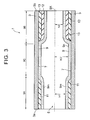
- the catalyst layer 9 is formed to satisfy a condition of h3 > h1 > h2, where h1 indicates a distance from the central axis 5X of the through hole 5 to an inner surface 9m of the catalyst layer 9 in the first region 9A, h2 indicates a distance from the central axis 5X of the through hole 5 to the inner surface 9m of the catalyst layer 9 in the second region 9B, and h3 indicates a distance from the central axis 5X of the through hole 5 to the inner surface 9m of the catalyst layer 9 in the third region 9C.
- the catalyst layer 9 is formed such that the distance h1 from the central axis 5X of the through hole 5 to the inner surface 9m of the catalyst layer 9 in the first region 9A is smaller the distance h3 from the central axis 5X of the through hole 5 to the inner surface 9m of the catalyst layer 9 in the third region 9C, but is larger than the distance h2 from the central axis 5X of the through hole 5 to the inner surface 9m of the catalyst layer 9 in the second region 9B.
- the catalyst layer 9 is formed such that the inner surface 9m is recessed in the third region 9C toward the base material 3 relative to the first region 9A and the second region 9B so that a recessed portion 9n is formed.
- the recessed portion 9n is formed annularly along the inner wall surface 7 in a direction perpendicular to the central axis 5X of the through hole 5.
- the catalyst layer 9 is formed such that the inner surface 9m has different heights in the first region 9A and in the second region 9B.
- a dummy layer 11 is formed between the inner wall surface 7 of the base material 3 and the catalyst layer 9 in the first region 9A. Further, in the exhaust gas catalyst 1 according to the present embodiment, a dummy layer 12 and a dummy layer 13 are formed between the inner wall surface 7 and the catalyst layer 9 in the second region 9B. The dummy layer 11 is not formed in the second region 9B and the third region 9C. The dummy layer 12 and the dummy layer 13 are not formed in the first region 9A and in the third region 9C.
- a structure of the present embodiment which satisfies the condition of h3 > h1 > h2 is referred to as a recessed structure.
- the catalyst layer 9 is formed to have a film thickness of around 100 ⁇ m, for example.
- the dummy layers 11, 12, and 13 are formed to have a film thickness of around 40 ⁇ m, for example.
- the dummy layers 11, 12, and 13 are ground layers of the catalyst layer 9, and are made of a material such as alumina that does not contribute to an exhaust gas purification reaction, for example.
- a longitudinal length of the catalyst layer 9 is, for example, around 105 mm, which is the same as the length L of the base material 3.
- Each of the first region 9A, the second region 9B, and the third region 9C is configured such that a length along a direction of the central axis 5X of the through hole 5 is around 35 mm, for example.
- the third region 9C is configured to be continuous with the first region 9A and the second region 9B.
- the third region 9C namely, the recessed portion 9n is configured such that a center of its length along the direction of the central axis 5X of the through hole 5 is placed, for example, at a position of 50% of a length from the first end surface 3a to the second end surface 3b, that is, an overall length of the base material 3.
- the length of the recessed portion 9n is the length of the third region 9C.
- each of the dummy layers 11, 12, 13, and the like are formed such that: the base material 3 is immersed in a solution in a state where the end surfaces of the base material 3 are parallel to a liquid level of the solution, so as to form a film on the inner wall surface 7; and then, a sintering process of hardening the film is performed. Accordingly, each of the dummy layers can be partially formed by controlling a position of the base material 3 to be immersed in the solution.
- the catalyst layer 9 is made of the same composition in a whole region including the first region 9A, the second region 9B, and the third region 9C.
- the recessed portion 9n is formed on the inner surface 9m of the catalyst layer 9. This makes it possible to disturb flow of exhaust gas flowing from a first-end-surface-3a side or a second-end-surface-3b side to go along the through hole 5, thereby making it possible to improve diffusivity of the exhaust gas relative to the catalyst layer 9.
- Exhaust gas catalysts according to Comparative Examples 1 to 3 basically have the same configuration as the exhaust gas catalyst 1 according to the present embodiment, but is different in a configuration related to the distances h1, h2, h3 from the central axis 5X of the through hole 5 to the inner surface 9m of the catalyst layer 9.
- a dummy layer 11 is formed between an inner wall surface 7 and the catalyst layer 9 over a first region 9A, a second region 9B, and a third region 9C.
- a dummy layer 12, a dummy layer 13, and a dummy layer 14 are partially formed between an inner wall surface 7 and the catalyst layer 9 in a second region 9B.
- the dummy layers 12, 13, and 14 are not formed in a first region 9A and in a third region 9C.
- the dummy layer 14 is formed to have a film thickness of around 40 ⁇ m, similarly to the other dummy layers, for example.
- the dummy layer 14 is also formed by the same method as the other dummy layers.
- a catalyst layer 9 is formed so as to satisfy a condition of h1 > h3 > h2.
- a dummy layer 12 and a dummy layer 13 are formed between an inner wall surface 7 and the catalyst layer 9 in a second region 9B.
- the dummy layer 12 is formed between the inner wall surface 7 and the catalyst layer 9 in a third region 9C.
- the dummy layer 12 is not formed in a first region 9A.
- the dummy layer 13 is not formed in the first region 9A and the third region 9C.
- a structure of Comparative Example 3 is referred to as a two-step structure.
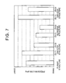
- FIGS. 7 to 9 are views showing results of measuring exhaust gas discharged from a gasoline engine through the catalysts of respective structures.
- a recessed structure corresponds to the present embodiment as illustrated in FIG. 3 .
- a planar structure corresponds to Comparative Example 1 illustrated in FIG. 4 .
- a one-step structure corresponds to Comparative Example 2 illustrated in FIG. 5 .
- a two-step structure corresponds to Comparative Example 3 illustrated in FIG. 6 .
- (In-1) indicates a case where the exhaust gas was flowed into the through hole 5 with the first-end-surface-3a side being taken as an exhaust-gas inflow side
- (In-2) indicates a case where the exhaust gas was flowed into the through hole 5 with the second-end-surface-3b side being taken as the exhaust-gas inflow side.
- a pressure loss is a difference between a pressure of the exhaust gas on one end surface side and a pressure of the exhaust gas on the other end surface side in a state where the exhaust gas is supplied from the one end surface side.
- a catalyst warming up time indicates a time after the catalyst is cooled down to a room temperature by flowing the exhaust gas into another line so that the exhaust gas does not flow into the catalyst, until the catalyst becomes active when the exhaust gas is switched to flow into a catalyst line.
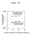
- a 50%-purification-achieved time in FIG. 8 indicates a time until a purification rate of hydrocarbon included in the exhaust gas reaches 50%.
- a 70%-purification-achieved time indicates a time until the purification rate of hydrocarbon included in the exhaust gas reaches 70%.
- a catalyst OSC characteristic is calculated as follows: an A/F rich state (a state of fuel/air mixture of which an air-fuel ratio is higher than a theoretical air-fuel ratio) is continued until an 02 sensor provided behind the catalyst is turned into a rich state; just after that, an A/F lean state (a state of fuel/air mixture of which the air-fuel ratio is lower than the theoretical air-fuel ratio) is caused; a time taken for the 02 sensor provided behind the catalyst to be turned into a lean state after the A/F lean state is caused is obtained; and the catalyst OSC characteristic is calculated from the time.
- ga10 indicates a case where an air intake amount of the engine is 10 g/sec
- ga30 indicates a case where the air intake amount of the engine is 30 g/sec.
- the intake air amount becomes high when a load of the engine increases or when an aperture of a throttle increases.
- the pressure loss tends to be higher in the case of (In-1) in which the first-end-surface-3a side is the exhaust gas inflow side, in any of the one-step structure, the recessed structure, and the two-step structure. Further, in the recessed structure, the pressure loss is decreased in either of the case (In-1) in which the first-end-surface-3a side is the exhaust-gas inflow side and the case (In-2) in which the second-end-surface-3b side is the exhaust-gas inflow side, in comparison with the planar structure, the one-step structure, and the two-step structure.
- the catalyst warming up time is shorter in the case (In-1) in which the first-end-surface-3a side is the exhaust-gas inflow side and the pressure loss is high.
- the recessed structure according to the present embodiment exhibits a pressure loss that is lower than those of the planar structure, the one-step structure, and the two-step structure, but has an excellent warming up characteristic. This is because gas diffusivity of the catalyst layer 9 is improved and purification performance is improved at a stage where the catalyst receives heat from the exhaust gas and is warmed up slowly from a front part of a gas inflow side.
- the ga10 with a low air intake amount is not so different in terms of a value of OSC.
- the ga30 with a high air intake amount in any of the one-step structure, the recessed structure, and the two-step structure, the case (In-2) in which the second-end-surface-3b side is the exhaust-gas inflow side and the pressure loss is low exhibits a high OSC.
- the flow of the exhaust gas can be disturbed, thereby making it possible to increase the gas diffusivity to diffuse the exhaust gas in the catalyst layer 9, and to improve purification performance.
- the exhaust gas catalyst 1 according to the present embodiment is configured such that the third region 9C of the catalyst layer 9 is recessed toward the base material 3 relative to the first region 9A and the second region 9B of the catalyst layer 9 so that the recessed portion 9n is formed. This makes it possible to disturb the flow of the exhaust gas flowing from the first-end-surface-3a side or the second-end-surface-3b side to go along the through hole 5, thereby making it possible to improve gas diffusivity to diffuse the exhaust gas in the catalyst layer 9. As a result, the exhaust gas catalyst 1 according to the present invention can achieve high purification performance.
- the catalyst layer 9 is also formed in the recessed portion 9n. Accordingly, high purification performance can be achieved by the base material 3 with a smaller capacity, in comparison with a case where a recessed portion is provided such that a catalyst layer is not formed in some part.
- the exhaust gas catalyst 1 can achieve high purification performance at low cost, in comparison with a case where a recessed portion is formed by placing catalyst carriers in three stages in a casing along an exhaust gas flow direction with respective separation portions provided therebetween.
- the inner surface 9m of the catalyst layer has different heights in the first region 9A of the catalyst layer 9 and in the second region 9B thereof. Accordingly, in comparison with a case where the inner surface 9m of the catalyst layer 9 does not have different heights in the first region 9A of the catalyst layer 9 and in the second region 9B thereof, the flow of the exhaust gas can be disturbed more.
- the exhaust gas catalyst 1 according to the present embodiment deals with a case where the length of the recessed portion 9n is 35 mm.
- the exhaust gas catalyst 1 according to the present embodiment is not limited to this, and the length of the recessed portion 9n may be changed.
- the exhaust gas catalyst 1 according to the present embodiment deals with a case where the center of the length of the third region 9C, namely, the recessed portion 9n is placed at a position of 50% of the length of the base material 3 from the first end surface 3a to the second end surface 3b.
- the exhaust gas catalyst 1 according to the present embodiment is not limited to this, and the position of the recessed portion 9n may be changed.
- FIGS. 11 to 12 are views showing results of measurements performed such that the exhaust gas discharged from the gasoline engine was flowed to respective catalysts different in the length of the recessed portion 9n.
- the measurement was performed by use of catalysts each having a structure in which the center of the length of the recessed portion 9n was placed at a position of 50% of the overall length from the first end surface 3a to the second end surface 3b and in which the length of the recessed portion 9n was set to 10%, 34%, or 60% of the overall length of the base material 3.
- the other structures except this are basically the same as FIG. 3 . Characteristics of these samples are shown in FIGS. 11 to 13 . Each of the characteristics was obtained when the exhaust gas was flowed into the through hole 5 with the first-end-surface-3a side being taken as the exhaust-gas inflow side.
- the pressure loss decreases as the length of the recessed portion 9n is longer.
- the catalyst OSC hardly changes depending on the length of the recessed portion 9n.
- FIG. 13 in the ga10 with a low air intake amount, an average emission of hydrocarbon during the OSC measurement is generally the same in each length.
- the ga30 with a high air intake amount when the length of the recessed portion 9n is 10% to 34% of the overall length, the emission is slightly good. However, when the length of the recessed portion 9n becomes longer than that, the emission suddenly turns worse.
- the length of the recessed portion 9n be around 30% relative to the overall length of the base material 3.
- FIGS. 15 to 17 are views showing results of measurements performed such that the exhaust gas discharged from the gasoline engine was flowed to respective catalysts different in the position of the recessed portion 9n.
- the measurements were performed by use of catalysts each having a structure in which the center of the recessed portion 9n having a length of 34% relative to the overall length of the base material 3 was placed at a position of 37%, 50%, or 62% of the overall length of the base material 3 from the first end surface 3a to the second end surface 3b.
- the other structures except this are basically the same as FIG. 3 .
- Characteristics of these catalysts are shown in FIGS. 15 to 17 . Each of the characteristics was obtained when the exhaust gas was flowed into the through hole 5 with the first-end-surface-3a side being taken as the exhaust-gas inflow side.
- the pressure loss becomes higher as the center of the length of the recessed portion 9n approaches the first-end-surface-3a side. This is because, as the center of the length of the recessed portion 9n approaches the first-end-surface-3a side, the length of the second region 9B where the inner surface 9m of the catalyst layer 9 is closer to the central axis 5X of the through hole 5 than in the first region 9A becomes longer. As illustrated in FIG. 16 , the catalyst OSC characteristic becomes larger as the center of the length of the recessed portion 9n approaches the second-end-surface-3b side. As illustrated in FIG.
- both the 50%-purification-achieved time and the 70%-purification-achieved time are shortened as the center of the length of the recessed portion 9n approaches the first-end-surface-3a side, and the warming up characteristic is improved.
- the recessed portion 9n is recessed with a length of not less than 5% but not more than 60%, desirably not less than 10% but not more than 50%, and further desirably around 30% of the overall length of the base material 3, within a range of 10% to 90%, desirably 20% to 80% of the overall length of the base material 3 from the first end surface 3a to the second end surface 3b. This makes it possible to improve gas diffusivity and to improve purification performance.
- the exhaust gas catalyst 1 is configured such that, when the first-end-surface-3a side is the exhaust-gas inflow side and the second-end-surface-3b side is an exhaust-gas outflow side, the third region 9C of the catalyst layer 9, namely, the recessed portion 9n is closer to the first-end-surface-3a side than to the second-end-surface-3b side. More specifically, for example, the center of the recessed portion 9n having a length of 34% of the overall length of the base material 3 is placed at a position of 37% of the overall length of the base material 3 from the first end surface 3a toward the second end surface 3b.
- the other structures except this are basically the same as FIG. 3 .
- a catalytic activity at the time of engine starting that is, the warming up characteristic is one of important functions as well as the gas diffusivity.
- the catalyst is warmed up from the gas inflow side. Accordingly, when the gas diffusivity is increased on the gas inflow side on which the temperature of the catalyst is higher, it is possible to increase the warming up characteristic of the catalyst as illustrated in FIG. 17 .
- the recessed portion 9n in the third region 9C is closer to the first-end-surface-3a side as the exhaust-gas inflow side than to the second-end-surface-3b side. Accordingly, at the time of engine starting, the catalyst is warmed up from the exhaust-gas inflow side, so that the flow of the exhaust gas can be disturbed on the first-end-surface-3a side on which the temperature is higher, thereby making it possible to improve the exhaust gas diffusivity on the first-end-surface-3a side as the exhaust-gas inflow side. As a result, the exhaust gas catalyst 1 according to the present embodiment can increase the warming up characteristic.
- the exhaust gas catalyst 1 is configured such that, when the first-end-surface-3a side is the exhaust-gas inflow side and the second-end-surface-3b side is the exhaust gas outflow side, the third region 9C of the catalyst layer 9, namely, the recessed portion 9n is closer to the second-end-surface-3b side than to the first-end-surface-3a side. More specifically, for example, the center of the recessed portion 9n having a length of 34% of the overall length of the base material 3 is placed at a position of 62% of the overall length of the base material 3 from the first end surface 3a toward the second end surface 3b.
- the other structures except this are basically the same as FIG. 3 .
- the recessed portion 9n in the third region 9C is closer to the second-end-surface-3b side as the exhaust-gas outflow side than to the first-end-surface-3a side. Accordingly, the flow of the exhaust gas can be disturbed on the second-end-surface-3b side, thereby making it possible to improve the exhaust gas diffusivity on the second-end-surface-3b side as the exhaust-gas outflow side. As a result, the exhaust gas catalyst 1 according to the present embodiment can increase the OSC characteristic, as illustrated in FIG. 16 .
- the exhaust gas catalyst 1 according to the present embodiment deals with a case where the dummy layer is formed between the inner wall surface and the catalyst layer as a technique of satisfying the condition of h3 > h1 > h2.
- the exhaust gas catalyst 1 according to the present embodiment is not limited to this, and a step may be formed on the inner wall surface 7 of the base material 3, so as to satisfy the condition of h3 > h1 > h2.
- the exhaust gas catalyst 1 according to the present embodiment deals with a case where the dummy layer made of a material that does not contribute to an exhaust gas purification reaction is used, as a technique of satisfying the condition of h3 > h1 > h2.
- the exhaust gas catalyst 1 according to the present embodiment is not limited to this, and a catalysis layer different in type from the catalyst layer 9 may be used.
- the exhaust gas catalyst 1 according to the present embodiment deals with a case where the third region 9C serving as the recessed portion 9n is continuous with both the first region 9A and the second region 9B as sections of the catalyst layer 9.
- the exhaust gas catalyst 1 according to the present embodiment is not limited to this, and another region having a different height from the first region 9A, the second region 9B, and the third region 9C may be formed at least between the third region 9C and the first region 9A or between the third region 9C and the second region 9B.
- the exhaust gas catalyst 1 according to the present embodiment deals with a case where a sectional shape of the through hole 5, perpendicular to the central axis 5X, is a rectangular shape.
- the exhaust gas catalyst 1 according to the present embodiment is not limited to this, and the sectional shape of the through hole 5 may be formed in other shapes such as a circular shape, a hexagonal shape, or an octagonal shape.
- the exhaust gas catalyst of the present invention yields an effect of achieving high purification performance, and is useful for an exhaust gas catalyst for purifying exhaust gas discharged from an internal combustion engine such as a gasoline engine or a diesel engine.
Landscapes
- Chemical & Material Sciences (AREA)
- Engineering & Computer Science (AREA)
- Chemical Kinetics & Catalysis (AREA)
- Materials Engineering (AREA)
- Organic Chemistry (AREA)
- Combustion & Propulsion (AREA)
- General Engineering & Computer Science (AREA)
- Mechanical Engineering (AREA)
- Health & Medical Sciences (AREA)
- Ceramic Engineering (AREA)
- Environmental & Geological Engineering (AREA)
- Oil, Petroleum & Natural Gas (AREA)
- General Chemical & Material Sciences (AREA)
- Analytical Chemistry (AREA)
- Biomedical Technology (AREA)
- Toxicology (AREA)
- Catalysts (AREA)
- Exhaust Gas Treatment By Means Of Catalyst (AREA)
- Exhaust Gas After Treatment (AREA)
- Processes For Solid Components From Exhaust (AREA)
Abstract
Description
- The present invention relates to an exhaust gas catalyst for purifying exhaust gas discharged from an internal combustion engine.
- As an exhaust gas catalyst for purifying exhaust gas discharged from an internal combustion engine, an exhaust gas catalyst configured such that a through hole is formed in a base material and a catalytic layer is provided on an inner wall surface formed by the through hole is described in the following prior art documents.
-
Patent Document 1 describes an exhaust gas catalyst converter configured such that catalyst carriers are placed in three stages in a casing along an exhaust gas flow direction with respective separation portions provided therebetween, and a pressure loss of each of the catalyst carriers is set to increase toward an outlet side, so that exhaust gas is stirred at the separation portions to be dispersed in a whole area, thereby improving purification efficiency. -
Patent Document 2 describes an exhaust gas catalyst configured such that a catalyst portion from one side of a cell and a catalyst portion from the other side thereof are distanced from each other so as not to overlap with each other, thereby restraining an increase in a pressure loss due to the overlap between the catalyst portions. -
Patent Document 3 describes an exhaust gas catalyst of which a thickness of a catalyst layer is decreased from both an upstream side and a downstream side of a through hole toward its center, so as to decrease a pressure loss of exhaust gas. -
- Patent Document 1: Japanese Patent Application Publication No.
9-195757 JP 9-195757 A - Patent Document 2: Japanese Patent Application Publication No.
2005-334801 JP 2005-334801 A - Patent Document 3: Japanese Patent Application Publication No.
2011-212508 JP 2011-212508 A - In the meantime, a purification reaction of exhaust gas in a catalyst is determined by a reaction speed of each gas component, and a diffusion speed of the exhaust gas. Generally, the reaction speed is rate-limiting in a low-temperature range of 400 °C or less, while the diffusion speed is rate-limiting in a high-temperature range of 500 °C or more because the reaction speed is increased sufficiently, which, however, changes depending on precious metal species of the catalyst, a carrying amount thereof, and the like.
- Exhaust gas of the internal combustion engine is generally discharged from each cylinder consecutively, so the exhaust gas pulsates. The exhaust gas also pulsates when the exhaust gas passes through an inside (through hole) of the catalyst. Since the flow of the exhaust gas is disturbed by the pulsation, gas diffusivity is high, which enables high purification efficiency by the catalyst. The gas diffusivity indicates that exhaust gas is diffused in the catalyst layer.
- However, in a case where an air intake amount of the internal combustion engine is large, an exhaust-gas flow speed becomes fast, and therefore, a diffusion speed is insufficient relative to an amount of the exhaust gas. This causes such a concern that the exhaust gas cannot be completely purified by the catalyst. Further, in terms of a decrease in a pressure loss in the catalyst, it is demanded that a high purification function be achieved with a catalyst having a smaller base material capacity.
- The present invention is accomplished in order to solve the above conventional problem, and is intended to provide an exhaust gas catalyst that can achieve high purification performance.
- In order to achieve the above object, an exhaust gas catalyst according to the present invention includes: a base material having a first end surface, a second end surface, and a plurality of inner wall surfaces formed by a plurality of through holes penetrating therethrough from the first end surface to the second end surface; and a plurality of catalyst layers formed on the plurality of inner wall surfaces, respectively, wherein: each of the through holes has a central axis; each of the catalyst layers is sectioned into a first region extending from the first end surface toward the second end surface by a predetermined distance, a second region extending from the second end surface toward the first end surface by a predetermined distance, and a third region placed between the first region and the second region; and the catalyst layer is formed such that a distance from the central axis of the through hole to an inner surface of the catalyst layer in the first region of the catalyst layer is smaller than a distance from the central axis of the through hole to the inner surface of the catalyst layer in the third region of the catalyst layer, but larger than a distance from the central axis of the through hole to the inner surface of the catalyst layer in the second region of the catalyst layer.
- In such a configuration, the exhaust gas catalyst according to the present invention is configured such that the third region of the catalyst layer is recessed toward the base material relative to the first region and the second region of the catalyst layer so that a recessed portion is formed. This accordingly makes it possible to disturb flow of exhaust gas flowing from a first-end-surface side or a second-end-surface side to go along the through hole, thereby making it possible to improve diffusivity of the exhaust gas relative to the catalyst layer. As a result, the exhaust gas catalyst according to the present invention can achieve high purification performance.
- Further, in the exhaust gas catalyst according to the present invention, the catalyst layer is also formed in the recessed portion. Accordingly, in comparison with a case where a recessed portion is provided such that a catalyst layer is not formed in some part, high purification performance can be achieved by a base material with a smaller capacity.
- Further, in the exhaust gas catalyst according to the present invention, the recessed portion is formed inside the base material. Accordingly, high purification performance can be achieved at low cost, in comparison with a case where a recessed portion is formed by placing catalyst carriers in three stages in a casing along an exhaust gas flow direction with respective separation portions provided therebetween.
- In the exhaust gas catalyst according to the present invention, when the first-end-surface side is an exhaust-gas inflow side and the second-end-surface side is an exhaust-gas outflow side, the third region is closer to the first-end-surface side than to the second-end-surface side.
- In such a configuration, the exhaust gas catalyst according to the present invention is configured such that the recessed portion in the third region is closer to the first-end-surface side as the exhaust-gas inflow side than to the second-end-surface side. Accordingly, at the time of engine starting, the catalyst layer is warmed up from the exhaust-gas inflow side, so that the flow of the exhaust gas can be disturbed on the first-end-surface side on which a temperature of the catalyst layer is higher, thereby making it possible to improve the exhaust gas diffusivity on the first-end-surface side as the exhaust-gas inflow side. As a result, the exhaust gas catalyst according to the present invention can increase a warming up characteristic.
- In the exhaust gas catalyst according to the present invention, when the first-end-surface side is an exhaust-gas inflow side and the second-end-surface side is an exhaust-gas outflow side, the third region is closer to the second-end-surface side than to the first-end-surface side.
- In such a configuration, the exhaust gas catalyst according to the present invention is configured such that the recessed portion in the third region is closer to the second-end-surface side as the exhaust-gas outflow side than to the first-end-surface side. Accordingly, the flow of the exhaust gas can be disturbed on the second-end-surface side, thereby making it possible to improve the exhaust gas diffusivity on the second-end-surface side as the exhaust-gas outflow side. As a result, the exhaust gas catalyst according to the present invention can increase an OSC (Oxygen Storage Capacity) characteristic.
- According to the present invention, it is possible to provide an exhaust gas catalyst that can achieve high purification performance.
-
- [
FIG. 1] FIG. 1 is a view illustrating a schematic configuration of an exhaust gas catalyst according to an embodiment of the present invention (FIG. 1(a) is a perspective view, andFIG. 1(b) is a side view ofFIG. 1(a) when viewed from a first-end-surface side). - [
FIG. 2] FIG. 2 is a view illustrating part ofFIG. 1(b) in an enlarged manner. - [
FIG. 3] FIG. 3 is a sectional view illustrating a sectional structure taken along a line a-a inFIG. 2 . - [
FIG. 4] FIG. 4 is a sectional view illustrating a sectional structure of an exhaust gas catalyst of Comparative Example 1. - [
FIG. 5] FIG. 5 is a sectional view illustrating a sectional structure of an exhaust gas catalyst of Comparative Example 2. - [
FIG. 6] FIG. 6 is a sectional view illustrating a sectional structure of an exhaust gas catalyst of Comparative Example 3. - [
FIG. 7] FIG. 7 is a graph showing results of pressure-loss measurement of the exhaust gas catalyst of the present embodiment and the exhaust gas catalysts of the comparative examples. - [
FIG. 8] FIG. 8 is a graph showing results of a catalyst warming up characteristic of the exhaust gas catalyst of the embodiment of the present invention and the exhaust gas catalysts of the comparative examples. - [
FIG. 9] FIG. 9 is a graph showing results of catalyst OSC measurement of the exhaust gas catalyst of the embodiment of the present invention and the exhaust gas catalysts of the comparative examples. - [
FIG. 10] FIG. 10 is a sectional view to describe a position of a recessed portion in the exhaust gas catalyst according to the embodiment of the present invention. - [
FIG. 11] FIG. 11 is a graph illustrating a relationship between a length of the recessed portion and a pressure loss in the exhaust gas catalyst according to the embodiment of the present invention. - [
FIG. 12] FIG. 12 is a graph illustrating a relationship between the length of the recessed portion and a catalyst OSC in the exhaust gas catalyst according to the embodiment of the present invention. - [
FIG. 13] FIG. 13 is a graph illustrating a relationship between the length of the recessed portion and an average emission during OSC measurement in the exhaust gas catalyst according to the embodiment of the present invention. - [
FIG. 14] FIG. 14 is a sectional view to describe the position of the recessed portion in the exhaust gas catalyst according to the embodiment of the present invention. - [
FIG. 15] FIG. 15 is a graph showing a relationship between a central position of the recessed portion and the pressure loss in the exhaust gas catalyst according to the embodiment of the present invention. - [
FIG. 16] FIG. 16 is a graph showing a relationship between the central position of the recessed portion and the catalyst OSC in the exhaust gas catalyst according to the embodiment of the present invention. - [
FIG. 17] FIG. 17 is a graph showing a relationship between the central position of the recessed portion and a catalyst warming up time in the exhaust gas catalyst according to the embodiment of the present invention. - [
FIG. 18] FIG. 18 is a sectional view illustrating a sectional structure of the exhaust gas catalyst according to the embodiment of the present invention. - [
FIG. 19] FIG. 19 is a sectional view illustrating a sectional structure of the exhaust gas catalyst according to the embodiment of the present invention. - An exhaust gas catalyst according to an embodiment of the present invention will be described below with reference to the drawings. The following embodiment deals with an example in which the present invention is applied to an exhaust gas catalyst for purifying exhaust gas discharged from a gasoline engine as an internal combustion engine. Note that
FIGS. 4 to 6 ,FIG. 10 ,FIG. 14 ,FIG. 18 , andFIG. 19 are sectional views each illustrating a sectional structure taken at the same position as a line a-a inFIG. 2(b) . - Initially described is a configuration of an exhaust gas catalyst according to the embodiment of the present invention.
- The
exhaust gas catalyst 1 according to the present embodiment includes abase material 3 and acatalyst layer 9 as illustrated inFIGS. 1 to 3 . - The
base material 3 includes afirst end surface 3a, asecond end surface 3b, and inner wall surfaces 7 formed by throughholes 5 penetrating therethrough from thefirst end surface 3a to thesecond end surface 3b. A plurality of throughholes 5 is formed, so that a plurality of inner wall surfaces 7 is formed by the plurality of throughholes 5. - The
base material 3 is a monolith honeycomb base material made of heat-resistant ceramics such as cordierite, for example. Thebase material 3 has an appearance formed in a circular column shape, for example. Thebase material 3 is configured such that a length L thereof in a longitudinal direction is around 105 mm and a diameter R thereof is around 103 mm, for example. - The through
hole 5 has acentral axis 5X. For example, the throughhole 5 is configured such that a sectional shape perpendicular to thecentral axis 5X is a rectangular shape, and a distance between the inner wall surfaces 7 opposed to each other is around 950 µm, for example. - A
catalyst layer 9 is formed on each of the plurality of inner wall surfaces 7. Thecatalyst layer 9 is made of a material including alumina (Al2O3) as a carrier, platinum (Pt) as active species, rhodium (Rh), ceria-zirconia (CeO2-ZrO2) as an OSC substance, and the like. - As illustrated in
FIG. 3 , in a direction of thecentral axis 5X of the throughhole 5, thecatalyst layer 9 is sectioned into afirst region 9A extending from thefirst end surface 3a toward thesecond end surface 3b by a predetermined distance, asecond region 9B extending from thesecond end surface 3b toward thefirst end surface 3a by a predetermined distance, and athird region 9C placed between thefirst region 9A and thesecond region 9B. Thecatalyst layer 9 is formed to satisfy a condition of h3 > h1 > h2, where h1 indicates a distance from thecentral axis 5X of the throughhole 5 to aninner surface 9m of thecatalyst layer 9 in thefirst region 9A, h2 indicates a distance from thecentral axis 5X of the throughhole 5 to theinner surface 9m of thecatalyst layer 9 in thesecond region 9B, and h3 indicates a distance from thecentral axis 5X of the throughhole 5 to theinner surface 9m of thecatalyst layer 9 in thethird region 9C. - That is, the
catalyst layer 9 is formed such that the distance h1 from thecentral axis 5X of the throughhole 5 to theinner surface 9m of thecatalyst layer 9 in thefirst region 9A is smaller the distance h3 from thecentral axis 5X of the throughhole 5 to theinner surface 9m of thecatalyst layer 9 in thethird region 9C, but is larger than the distance h2 from thecentral axis 5X of the throughhole 5 to theinner surface 9m of thecatalyst layer 9 in thesecond region 9B. - Further, the
catalyst layer 9 is formed such that theinner surface 9m is recessed in thethird region 9C toward thebase material 3 relative to thefirst region 9A and thesecond region 9B so that a recessedportion 9n is formed. The recessedportion 9n is formed annularly along theinner wall surface 7 in a direction perpendicular to thecentral axis 5X of the throughhole 5. - Further, the
catalyst layer 9 is formed such that theinner surface 9m has different heights in thefirst region 9A and in thesecond region 9B. - In the
exhaust gas catalyst 1 according to the present embodiment, in order to satisfy the condition of h3 > h1 > h2, adummy layer 11 is formed between theinner wall surface 7 of thebase material 3 and thecatalyst layer 9 in thefirst region 9A. Further, in theexhaust gas catalyst 1 according to the present embodiment, adummy layer 12 and adummy layer 13 are formed between theinner wall surface 7 and thecatalyst layer 9 in thesecond region 9B. Thedummy layer 11 is not formed in thesecond region 9B and thethird region 9C. Thedummy layer 12 and thedummy layer 13 are not formed in thefirst region 9A and in thethird region 9C. A structure of the present embodiment which satisfies the condition of h3 > h1 > h2 is referred to as a recessed structure. - The
catalyst layer 9 is formed to have a film thickness of around 100 µm, for example. The dummy layers 11, 12, and 13 are formed to have a film thickness of around 40 µm, for example. The dummy layers 11, 12, and 13 are ground layers of thecatalyst layer 9, and are made of a material such as alumina that does not contribute to an exhaust gas purification reaction, for example. - A longitudinal length of the
catalyst layer 9 is, for example, around 105 mm, which is the same as the length L of thebase material 3. Each of thefirst region 9A, thesecond region 9B, and thethird region 9C is configured such that a length along a direction of thecentral axis 5X of the throughhole 5 is around 35 mm, for example. Thethird region 9C is configured to be continuous with thefirst region 9A and thesecond region 9B. - The
third region 9C, namely, the recessedportion 9n is configured such that a center of its length along the direction of thecentral axis 5X of the throughhole 5 is placed, for example, at a position of 50% of a length from thefirst end surface 3a to thesecond end surface 3b, that is, an overall length of thebase material 3. The length of the recessedportion 9n is the length of thethird region 9C. - The
catalyst layer 9, each of the dummy layers 11, 12, 13, and the like are formed such that: thebase material 3 is immersed in a solution in a state where the end surfaces of thebase material 3 are parallel to a liquid level of the solution, so as to form a film on theinner wall surface 7; and then, a sintering process of hardening the film is performed. Accordingly, each of the dummy layers can be partially formed by controlling a position of thebase material 3 to be immersed in the solution. Here, thecatalyst layer 9 is made of the same composition in a whole region including thefirst region 9A, thesecond region 9B, and thethird region 9C. - In the
exhaust gas catalyst 1 configured as such, the recessedportion 9n is formed on theinner surface 9m of thecatalyst layer 9. This makes it possible to disturb flow of exhaust gas flowing from a first-end-surface-3a side or a second-end-surface-3b side to go along the throughhole 5, thereby making it possible to improve diffusivity of the exhaust gas relative to thecatalyst layer 9. - Next will be described characteristics of the
exhaust gas catalyst 1 according to the present embodiment with reference to Comparative Examples 1 to 3. - Exhaust gas catalysts according to Comparative Examples 1 to 3 basically have the same configuration as the
exhaust gas catalyst 1 according to the present embodiment, but is different in a configuration related to the distances h1, h2, h3 from thecentral axis 5X of the throughhole 5 to theinner surface 9m of thecatalyst layer 9. - That is, as illustrated in
FIG. 4 , in anexhaust gas catalyst 21 of Comparative Example 1, acatalyst layer 9 is formed so as to satisfy a condition of h1 = h2 = h3. In order to satisfy this condition, in Comparative Example 1, adummy layer 11 is formed between aninner wall surface 7 and thecatalyst layer 9 over afirst region 9A, asecond region 9B, and athird region 9C. A structure of Comparative Example 1 which satisfies the condition of h1 = h2 = h3 is referred to as a planar structure. - As illustrated in
FIG. 5 , in anexhaust gas catalyst 22 of Comparative Example 2, acatalyst layer 9 is formed so as to satisfy a condition of h1 = h3 > h2. In order to satisfy the condition, in Comparative Example 2, adummy layer 12, adummy layer 13, and adummy layer 14 are partially formed between aninner wall surface 7 and thecatalyst layer 9 in asecond region 9B. The dummy layers 12, 13, and 14 are not formed in afirst region 9A and in athird region 9C. A structure of Comparative Example 2 which satisfies the condition of h1 = h3 > h2 is referred to as a one-step structure. Thedummy layer 14 is formed to have a film thickness of around 40 µm, similarly to the other dummy layers, for example. Thedummy layer 14 is also formed by the same method as the other dummy layers. - As illustrated in
FIG. 6 , in anexhaust gas catalyst 23 of Comparative Example 3, acatalyst layer 9 is formed so as to satisfy a condition of h1 > h3 > h2. In order to satisfy the condition, in Comparative Example 3, adummy layer 12 and adummy layer 13 are formed between aninner wall surface 7 and thecatalyst layer 9 in asecond region 9B. Further, in Comparative Example 3, thedummy layer 12 is formed between theinner wall surface 7 and thecatalyst layer 9 in athird region 9C. Thedummy layer 12 is not formed in afirst region 9A. Thedummy layer 13 is not formed in thefirst region 9A and thethird region 9C. A structure of Comparative Example 3 is referred to as a two-step structure. -
FIGS. 7 to 9 are views showing results of measuring exhaust gas discharged from a gasoline engine through the catalysts of respective structures. InFIGS. 7 to 9 , a recessed structure corresponds to the present embodiment as illustrated inFIG. 3 . A planar structure corresponds to Comparative Example 1 illustrated inFIG. 4 . A one-step structure corresponds to Comparative Example 2 illustrated inFIG. 5 . A two-step structure corresponds to Comparative Example 3 illustrated inFIG. 6 . - Further, in
FIGS. 7 to 9 , (In-1) indicates a case where the exhaust gas was flowed into the throughhole 5 with the first-end-surface-3a side being taken as an exhaust-gas inflow side, and (In-2) indicates a case where the exhaust gas was flowed into the throughhole 5 with the second-end-surface-3b side being taken as the exhaust-gas inflow side. - Further, in
FIG. 7 , a pressure loss (kPa) is a difference between a pressure of the exhaust gas on one end surface side and a pressure of the exhaust gas on the other end surface side in a state where the exhaust gas is supplied from the one end surface side. - Further, in
FIG. 8 , a catalyst warming up time (sec) indicates a time after the catalyst is cooled down to a room temperature by flowing the exhaust gas into another line so that the exhaust gas does not flow into the catalyst, until the catalyst becomes active when the exhaust gas is switched to flow into a catalyst line. - Here, a 50%-purification-achieved time in
FIG. 8 indicates a time until a purification rate of hydrocarbon included in the exhaust gas reaches 50%. Similarly, a 70%-purification-achieved time indicates a time until the purification rate of hydrocarbon included in the exhaust gas reaches 70%. - Further, in
FIG. 9 , a catalyst OSC characteristic is calculated as follows: an A/F rich state (a state of fuel/air mixture of which an air-fuel ratio is higher than a theoretical air-fuel ratio) is continued until an 02 sensor provided behind the catalyst is turned into a rich state; just after that, an A/F lean state (a state of fuel/air mixture of which the air-fuel ratio is lower than the theoretical air-fuel ratio) is caused; a time taken for the 02 sensor provided behind the catalyst to be turned into a lean state after the A/F lean state is caused is obtained; and the catalyst OSC characteristic is calculated from the time. Here, ga10 indicates a case where an air intake amount of the engine is 10 g/sec, and ga30 indicates a case where the air intake amount of the engine is 30 g/sec. The intake air amount becomes high when a load of the engine increases or when an aperture of a throttle increases. - As illustrated in
FIG. 7 , the pressure loss tends to be higher in the case of (In-1) in which the first-end-surface-3a side is the exhaust gas inflow side, in any of the one-step structure, the recessed structure, and the two-step structure. Further, in the recessed structure, the pressure loss is decreased in either of the case (In-1) in which the first-end-surface-3a side is the exhaust-gas inflow side and the case (In-2) in which the second-end-surface-3b side is the exhaust-gas inflow side, in comparison with the planar structure, the one-step structure, and the two-step structure. - As illustrated in
FIG. 8 , in any of the one-step structure, the recessed structure, and the two-step structure, the catalyst warming up time is shorter in the case (In-1) in which the first-end-surface-3a side is the exhaust-gas inflow side and the pressure loss is high. Here, the recessed structure according to the present embodiment exhibits a pressure loss that is lower than those of the planar structure, the one-step structure, and the two-step structure, but has an excellent warming up characteristic. This is because gas diffusivity of thecatalyst layer 9 is improved and purification performance is improved at a stage where the catalyst receives heat from the exhaust gas and is warmed up slowly from a front part of a gas inflow side. - As illustrated in
FIG. 9 , the ga10 with a low air intake amount is not so different in terms of a value of OSC. In contrast, in the ga30 with a high air intake amount, in any of the one-step structure, the recessed structure, and the two-step structure, the case (In-2) in which the second-end-surface-3b side is the exhaust-gas inflow side and the pressure loss is low exhibits a high OSC. - In this examination, since oxygen discharge of the catalyst is caused from the front part on the gas inflow side, the front part of the catalyst on the gas inflow side finishes reacting in any of the structures, and a structure without a dummy layer in a rear part of the catalyst on a gas outflow side is decreased in an exhaust-gas flow speed, and thus, has a larger OSC characteristic. Although the recessed structure of
FIG. 3 has a dummy layer in a rear part of the catalyst on the gas outflow side, the OSC characteristic of the catalyst is large. This means that diffusivity inside the catalyst is improved, so that an oxygen-releasable amount increases, and thus, the recessed structure has a large OSC. - Based on the foregoing, by forming the recessed
portion 9n inside the catalyst, the flow of the exhaust gas can be disturbed, thereby making it possible to increase the gas diffusivity to diffuse the exhaust gas in thecatalyst layer 9, and to improve purification performance. - Next will be described an effect of the
exhaust gas catalyst 1 according to the present embodiment. - The
exhaust gas catalyst 1 according to the present embodiment is configured such that thethird region 9C of thecatalyst layer 9 is recessed toward thebase material 3 relative to thefirst region 9A and thesecond region 9B of thecatalyst layer 9 so that the recessedportion 9n is formed. This makes it possible to disturb the flow of the exhaust gas flowing from the first-end-surface-3a side or the second-end-surface-3b side to go along the throughhole 5, thereby making it possible to improve gas diffusivity to diffuse the exhaust gas in thecatalyst layer 9. As a result, theexhaust gas catalyst 1 according to the present invention can achieve high purification performance. - In the
exhaust gas catalyst 1 according to the present embodiment, thecatalyst layer 9 is also formed in the recessedportion 9n. Accordingly, high purification performance can be achieved by thebase material 3 with a smaller capacity, in comparison with a case where a recessed portion is provided such that a catalyst layer is not formed in some part. - Since the recessed
portion 9n is formed inside thebase material 3, theexhaust gas catalyst 1 according to the present embodiment can achieve high purification performance at low cost, in comparison with a case where a recessed portion is formed by placing catalyst carriers in three stages in a casing along an exhaust gas flow direction with respective separation portions provided therebetween. - In the
exhaust gas catalyst 1 according to the present embodiment, theinner surface 9m of the catalyst layer has different heights in thefirst region 9A of thecatalyst layer 9 and in thesecond region 9B thereof. Accordingly, in comparison with a case where theinner surface 9m of thecatalyst layer 9 does not have different heights in thefirst region 9A of thecatalyst layer 9 and in thesecond region 9B thereof, the flow of the exhaust gas can be disturbed more. - The
exhaust gas catalyst 1 according to the present embodiment deals with a case where the length of the recessedportion 9n is 35 mm. However, theexhaust gas catalyst 1 according to the present embodiment is not limited to this, and the length of the recessedportion 9n may be changed. - Further, the
exhaust gas catalyst 1 according to the present embodiment deals with a case where the center of the length of thethird region 9C, namely, the recessedportion 9n is placed at a position of 50% of the length of thebase material 3 from thefirst end surface 3a to thesecond end surface 3b. However, theexhaust gas catalyst 1 according to the present embodiment is not limited to this, and the position of the recessedportion 9n may be changed. - Next will be described the length of the recessed
portion 9n of theexhaust gas catalyst 1 according to the present embodiment, with reference toFIGS. 10 to 13 . -
FIGS. 11 to 12 are views showing results of measurements performed such that the exhaust gas discharged from the gasoline engine was flowed to respective catalysts different in the length of the recessedportion 9n. As illustrated inFIG. 10 , the measurement was performed by use of catalysts each having a structure in which the center of the length of the recessedportion 9n was placed at a position of 50% of the overall length from thefirst end surface 3a to thesecond end surface 3b and in which the length of the recessedportion 9n was set to 10%, 34%, or 60% of the overall length of thebase material 3. The other structures except this are basically the same asFIG. 3 . Characteristics of these samples are shown inFIGS. 11 to 13 . Each of the characteristics was obtained when the exhaust gas was flowed into the throughhole 5 with the first-end-surface-3a side being taken as the exhaust-gas inflow side. - As illustrated in
FIG. 11 , the pressure loss decreases as the length of the recessedportion 9n is longer. As illustrated inFIG. 12 , the catalyst OSC hardly changes depending on the length of the recessedportion 9n. As illustrated inFIG. 13 , in the ga10 with a low air intake amount, an average emission of hydrocarbon during the OSC measurement is generally the same in each length. On the other hand, in the ga30 with a high air intake amount, when the length of the recessedportion 9n is 10% to 34% of the overall length, the emission is slightly good. However, when the length of the recessedportion 9n becomes longer than that, the emission suddenly turns worse. - Based on the foregoing, it is preferable that the length of the recessed
portion 9n be around 30% relative to the overall length of thebase material 3. - Next will be described a position of the recessed
portion 9n of theexhaust gas catalyst 1 according to the present embodiment, with reference toFIGS. 14 to 17 . -
FIGS. 15 to 17 are views showing results of measurements performed such that the exhaust gas discharged from the gasoline engine was flowed to respective catalysts different in the position of the recessedportion 9n. As illustrated inFIG. 14 , the measurements were performed by use of catalysts each having a structure in which the center of the recessedportion 9n having a length of 34% relative to the overall length of thebase material 3 was placed at a position of 37%, 50%, or 62% of the overall length of thebase material 3 from thefirst end surface 3a to thesecond end surface 3b. The other structures except this are basically the same asFIG. 3 . Characteristics of these catalysts are shown inFIGS. 15 to 17 . Each of the characteristics was obtained when the exhaust gas was flowed into the throughhole 5 with the first-end-surface-3a side being taken as the exhaust-gas inflow side. - As illustrated in
FIG. 15 , the pressure loss becomes higher as the center of the length of the recessedportion 9n approaches the first-end-surface-3a side. This is because, as the center of the length of the recessedportion 9n approaches the first-end-surface-3a side, the length of thesecond region 9B where theinner surface 9m of thecatalyst layer 9 is closer to thecentral axis 5X of the throughhole 5 than in thefirst region 9A becomes longer. As illustrated inFIG. 16 , the catalyst OSC characteristic becomes larger as the center of the length of the recessedportion 9n approaches the second-end-surface-3b side. As illustrated inFIG. 17 , in terms of the catalyst warming up time, both the 50%-purification-achieved time and the 70%-purification-achieved time are shortened as the center of the length of the recessedportion 9n approaches the first-end-surface-3a side, and the warming up characteristic is improved. - Based on the foregoing, the recessed
portion 9n is recessed with a length of not less than 5% but not more than 60%, desirably not less than 10% but not more than 50%, and further desirably around 30% of the overall length of thebase material 3, within a range of 10% to 90%, desirably 20% to 80% of the overall length of thebase material 3 from thefirst end surface 3a to thesecond end surface 3b. This makes it possible to improve gas diffusivity and to improve purification performance. - Next will be described the position of the recessed
portion 9n, more specifically. - As illustrated in
FIG. 18 , theexhaust gas catalyst 1 according to the present embodiment is configured such that, when the first-end-surface-3a side is the exhaust-gas inflow side and the second-end-surface-3b side is an exhaust-gas outflow side, thethird region 9C of thecatalyst layer 9, namely, the recessedportion 9n is closer to the first-end-surface-3a side than to the second-end-surface-3b side. More specifically, for example, the center of the recessedportion 9n having a length of 34% of the overall length of thebase material 3 is placed at a position of 37% of the overall length of thebase material 3 from thefirst end surface 3a toward thesecond end surface 3b. The other structures except this are basically the same asFIG. 3 . - A catalytic activity at the time of engine starting, that is, the warming up characteristic is one of important functions as well as the gas diffusivity. At the time of engine starting, the catalyst is warmed up from the gas inflow side. Accordingly, when the gas diffusivity is increased on the gas inflow side on which the temperature of the catalyst is higher, it is possible to increase the warming up characteristic of the catalyst as illustrated in
FIG. 17 . - In the
exhaust gas catalyst 1 according to the present embodiment, the recessedportion 9n in thethird region 9C is closer to the first-end-surface-3a side as the exhaust-gas inflow side than to the second-end-surface-3b side. Accordingly, at the time of engine starting, the catalyst is warmed up from the exhaust-gas inflow side, so that the flow of the exhaust gas can be disturbed on the first-end-surface-3a side on which the temperature is higher, thereby making it possible to improve the exhaust gas diffusivity on the first-end-surface-3a side as the exhaust-gas inflow side. As a result, theexhaust gas catalyst 1 according to the present embodiment can increase the warming up characteristic. - As illustrated in
FIG. 19 , theexhaust gas catalyst 1 according to the present embodiment is configured such that, when the first-end-surface-3a side is the exhaust-gas inflow side and the second-end-surface-3b side is the exhaust gas outflow side, thethird region 9C of thecatalyst layer 9, namely, the recessedportion 9n is closer to the second-end-surface-3b side than to the first-end-surface-3a side. More specifically, for example, the center of the recessedportion 9n having a length of 34% of the overall length of thebase material 3 is placed at a position of 62% of the overall length of thebase material 3 from thefirst end surface 3a toward thesecond end surface 3b. The other structures except this are basically the same asFIG. 3 . - In the
exhaust gas catalyst 1 according to the present embodiment, the recessedportion 9n in thethird region 9C is closer to the second-end-surface-3b side as the exhaust-gas outflow side than to the first-end-surface-3a side. Accordingly, the flow of the exhaust gas can be disturbed on the second-end-surface-3b side, thereby making it possible to improve the exhaust gas diffusivity on the second-end-surface-3b side as the exhaust-gas outflow side. As a result, theexhaust gas catalyst 1 according to the present embodiment can increase the OSC characteristic, as illustrated inFIG. 16 . - The
exhaust gas catalyst 1 according to the present embodiment deals with a case where the dummy layer is formed between the inner wall surface and the catalyst layer as a technique of satisfying the condition of h3 > h1 > h2. However, theexhaust gas catalyst 1 according to the present embodiment is not limited to this, and a step may be formed on theinner wall surface 7 of thebase material 3, so as to satisfy the condition of h3 > h1 > h2. - The
exhaust gas catalyst 1 according to the present embodiment deals with a case where the dummy layer made of a material that does not contribute to an exhaust gas purification reaction is used, as a technique of satisfying the condition of h3 > h1 > h2. However, theexhaust gas catalyst 1 according to the present embodiment is not limited to this, and a catalysis layer different in type from thecatalyst layer 9 may be used. - Further, the
exhaust gas catalyst 1 according to the present embodiment deals with a case where thethird region 9C serving as the recessedportion 9n is continuous with both thefirst region 9A and thesecond region 9B as sections of thecatalyst layer 9. However, theexhaust gas catalyst 1 according to the present embodiment is not limited to this, and another region having a different height from thefirst region 9A, thesecond region 9B, and thethird region 9C may be formed at least between thethird region 9C and thefirst region 9A or between thethird region 9C and thesecond region 9B. - The
exhaust gas catalyst 1 according to the present embodiment deals with a case where a sectional shape of the throughhole 5, perpendicular to thecentral axis 5X, is a rectangular shape. However, theexhaust gas catalyst 1 according to the present embodiment is not limited to this, and the sectional shape of the throughhole 5 may be formed in other shapes such as a circular shape, a hexagonal shape, or an octagonal shape. - As described above, the exhaust gas catalyst of the present invention yields an effect of achieving high purification performance, and is useful for an exhaust gas catalyst for purifying exhaust gas discharged from an internal combustion engine such as a gasoline engine or a diesel engine.
- 1 ... exhaust gas catalyst, 3 ... base material, 3a ... first end surface, 3b ... second end surface, 5 ... through hole, 5X ... central axis, 7 ... inner wall surface, 9 ... catalyst layer, 9A ... first region, 9B ... second region, 9C ... third region, 9m ... inner surface, 9n ... recessed portion, 11, 12, 13, 14 ... dummy layer.
Claims (3)
- An exhaust gas catalyst characterised by comprising:a base material having a first end surface, a second end surface, and a plurality of inner wall surfaces formed by a plurality of through holes penetrating therethrough from the first end surface to the second end surface; anda plurality of catalyst layers formed on the plurality of inner wall surfaces, respectively, wherein:each of the through holes has a central axis;each of the catalyst layers is sectioned into a first region extending from the first end surface toward the second end surface by a predetermined distance, a second region extending from the second end surface toward the first end surface by a predetermined distance, and a third region placed between the first region and the second region; andthe catalyst layer is formed such that a distance from the central axis of the through hole to an inner surface of the catalyst layer in the first region of the catalyst layer is smaller than a distance from the central axis of the through hole to the inner surface of the catalyst layer in the third region of the catalyst layer, but larger than a distance from the central axis of the through hole to the inner surface of the catalyst layer in the second region of the catalyst layer.
- The exhaust gas catalyst according to claim 1, characterized in that:when the first end surface side is an exhaust gas inflow side and the second end surface side is an exhaust gas outflow side, the third region of the catalyst layer is closer to the first end surface side than to the second end surface side.
- The exhaust gas catalyst according to claim 1, characterized in that:when the first end surface side is an exhaust gas inflow side and the second end surface side is an exhaust gas outflow side, the third region of the catalyst layer is closer to the second end surface side than to the first end surface side.
Applications Claiming Priority (2)
| Application Number | Priority Date | Filing Date | Title |
|---|---|---|---|
| JP2012254363A JP5799938B2 (en) | 2012-11-20 | 2012-11-20 | Exhaust gas purification catalyst |
| PCT/JP2013/005656 WO2014080554A1 (en) | 2012-11-20 | 2013-09-25 | Catalyst for cleaning exhaust gas |
Publications (3)
| Publication Number | Publication Date |
|---|---|
| EP2875862A1 true EP2875862A1 (en) | 2015-05-27 |
| EP2875862A4 EP2875862A4 (en) | 2015-08-19 |
| EP2875862B1 EP2875862B1 (en) | 2019-06-05 |
Family
ID=50775752
Family Applications (1)
| Application Number | Title | Priority Date | Filing Date |
|---|---|---|---|
| EP13856424.0A Not-in-force EP2875862B1 (en) | 2012-11-20 | 2013-09-25 | Catalyst for cleaning exhaust gas |
Country Status (6)
| Country | Link |
|---|---|
| US (1) | US9694354B2 (en) |
| EP (1) | EP2875862B1 (en) |
| JP (1) | JP5799938B2 (en) |
| CN (1) | CN104582846B (en) |
| RU (1) | RU2600930C1 (en) |
| WO (1) | WO2014080554A1 (en) |
Cited By (1)
| Publication number | Priority date | Publication date | Assignee | Title |
|---|---|---|---|---|
| CN111828141A (en) * | 2019-04-22 | 2020-10-27 | 丰田自动车株式会社 | structure |
Families Citing this family (9)
| Publication number | Priority date | Publication date | Assignee | Title |
|---|---|---|---|---|
| EP2979761A4 (en) * | 2013-03-28 | 2017-01-18 | The Chugoku Electric Power Co., Inc. | Method for regenerating denitrification catalyst |
| JP6332003B2 (en) * | 2014-12-10 | 2018-05-30 | 株式会社デンソー | Honeycomb structure |
| USD780808S1 (en) | 2014-12-24 | 2017-03-07 | Ngk Insulators, Ltd. | Catalyst carrier for exhaust gas purification |
| USD785678S1 (en) * | 2014-12-24 | 2017-05-02 | Ngk Insulators, Ltd. | Catalyst carrier for exhaust gas purification |
| JP6545962B2 (en) | 2015-01-22 | 2019-07-17 | 株式会社キャタラー | Exhaust gas purification catalyst |
| EP3488928B1 (en) * | 2016-07-20 | 2020-08-19 | Umicore Shokubai Japan Co., Ltd. | Exhaust gas purification catalyst for internal combustion engine, and exhaust gas purifying method using exhaust gas purification catalyst |
| EP3488927B1 (en) | 2016-07-20 | 2020-03-04 | Umicore Shokubai Japan Co., Ltd. | Catalyst for purifying exhaust gas from internal combustion engine, and exhaust gas purification method using said catalyst |
| JP6244421B1 (en) * | 2016-07-27 | 2017-12-06 | 株式会社キャタラー | Exhaust gas purification catalyst manufacturing method and manufacturing apparatus |
| USD928912S1 (en) * | 2020-02-12 | 2021-08-24 | Unicat Catalyst Technologies, Inc. | Filter |
Family Cites Families (15)
| Publication number | Priority date | Publication date | Assignee | Title |
|---|---|---|---|---|
| NL7400525A (en) * | 1973-01-27 | 1974-07-30 | ||
| US4886711A (en) * | 1987-11-27 | 1989-12-12 | General Motors Corporation | Catalytic converter metal monolithic catalyst substrate |
| DE8900467U1 (en) * | 1989-01-17 | 1990-05-17 | Emitec Gesellschaft für Emissionstechnologie mbH, 5204 Lohmar | Metallic honeycomb body, preferably catalyst carrier body with microstructures for flow mixing |
| JPH09195757A (en) | 1996-01-18 | 1997-07-29 | Aichi Mach Ind Co Ltd | Catalytic converter for exhaust emission control |
| US20010026838A1 (en) * | 1996-06-21 | 2001-10-04 | Engelhard Corporation | Monolithic catalysts and related process for manufacture |
| BR9909986A (en) * | 1998-04-28 | 2000-12-26 | Engelhard Corp | Monolithic catalysts and related process for manufacturing |
| JP2005334801A (en) * | 2004-05-28 | 2005-12-08 | Cataler Corp | Exhaust gas purification catalyst |
| US7481983B2 (en) * | 2004-08-23 | 2009-01-27 | Basf Catalysts Llc | Zone coated catalyst to simultaneously reduce NOx and unreacted ammonia |
| JP5303131B2 (en) * | 2006-09-19 | 2013-10-02 | 株式会社日本自動車部品総合研究所 | Carbon-based material combustion catalyst and method for producing the same, catalyst carrier and method for producing the same |
| US7491373B2 (en) * | 2006-11-15 | 2009-02-17 | Corning Incorporated | Flow-through honeycomb substrate and exhaust after treatment system and method |
| JP2008178767A (en) * | 2007-01-23 | 2008-08-07 | Mazda Motor Corp | Diesel oxidation catalyst |
| DE102009018825A1 (en) * | 2009-04-24 | 2010-10-28 | Emitec Gesellschaft Für Emissionstechnologie Mbh | Sheet metal layer with anti-diffusion structures and metallic honeycomb body with at least one such sheet metal layer |
| WO2010131369A1 (en) * | 2009-05-15 | 2010-11-18 | トヨタ自動車株式会社 | Exhaust purifying catalyst and method of manufacturing the same |
| WO2011061841A1 (en) * | 2009-11-19 | 2011-05-26 | イビデン株式会社 | Honeycomb structure and exhaust gas purification apparatus |
| JP5555524B2 (en) * | 2010-03-31 | 2014-07-23 | 株式会社キャタラー | Exhaust gas purification catalyst |
-
2012
- 2012-11-20 JP JP2012254363A patent/JP5799938B2/en active Active
-
2013
- 2013-09-25 RU RU2015106066/04A patent/RU2600930C1/en active
- 2013-09-25 CN CN201380043404.2A patent/CN104582846B/en active Active
- 2013-09-25 EP EP13856424.0A patent/EP2875862B1/en not_active Not-in-force
- 2013-09-25 WO PCT/JP2013/005656 patent/WO2014080554A1/en not_active Ceased
- 2013-09-25 US US14/423,210 patent/US9694354B2/en active Active
Cited By (1)
| Publication number | Priority date | Publication date | Assignee | Title |
|---|---|---|---|---|
| CN111828141A (en) * | 2019-04-22 | 2020-10-27 | 丰田自动车株式会社 | structure |
Also Published As
| Publication number | Publication date |
|---|---|
| CN104582846B (en) | 2017-10-20 |
| JP2014100658A (en) | 2014-06-05 |
| US9694354B2 (en) | 2017-07-04 |
| US20150238951A1 (en) | 2015-08-27 |
| JP5799938B2 (en) | 2015-10-28 |
| WO2014080554A1 (en) | 2014-05-30 |
| CN104582846A (en) | 2015-04-29 |
| EP2875862B1 (en) | 2019-06-05 |
| EP2875862A4 (en) | 2015-08-19 |
| RU2600930C1 (en) | 2016-10-27 |
Similar Documents
| Publication | Publication Date | Title |
|---|---|---|
| EP2875862B1 (en) | Catalyst for cleaning exhaust gas | |
| US10213741B2 (en) | Exhaust gas purification catalyst for internal combustion engine | |
| JP5720949B2 (en) | Exhaust gas purification catalyst | |
| US10688476B2 (en) | Exhaust gas purification catalyst | |
| EP3434363B1 (en) | Exhaust gas purifying catalyst | |
| KR101006220B1 (en) | Exhaust gas purification catalyst | |
| CN103946182B (en) | Honeycomb structured body | |
| EP1952884B1 (en) | Catalyst for exhaust-gas purification | |
| CN104334255B (en) | Three-way-catalyst system | |
| KR20160016968A (en) | Three-way catalytic converter | |
| US20060128562A1 (en) | Exhaust gas purification catalyst | |
| CN114961940A (en) | Novel three-zone two-layer TWC catalyst for gasoline exhaust gas applications | |
| US20160151764A1 (en) | Exhaust Gas Purifying Catalyst | |
| CN104994951A (en) | Catalytic converter | |
| JP2005211794A (en) | Exhaust gas purification catalyst | |
| JP6206102B2 (en) | Catalytic converter | |
| US10280822B2 (en) | Exhaust gas purifying apparatus | |
| US20130315788A1 (en) | Catalytic converter | |
| JP6735912B2 (en) | Exhaust gas purification catalyst and exhaust gas purification method using the same | |
| JP2004230226A (en) | Automotive catalyst | |
| JP2010013969A (en) | Exhaust emission control device | |
| WO2025083918A1 (en) | Exhaust gas purification catalyst device | |
| JP2004181374A (en) | Exhaust gas purification catalyst | |
| JP2014100631A (en) | Consecutive catalyst for exhaust gas purification | |
| JP2016055218A (en) | Exhaust gas purification catalyst |
Legal Events
| Date | Code | Title | Description |
|---|---|---|---|
| PUAI | Public reference made under article 153(3) epc to a published international application that has entered the european phase |
Free format text: ORIGINAL CODE: 0009012 |
|
| 17P | Request for examination filed |
Effective date: 20150220 |
|
| AK | Designated contracting states |
Kind code of ref document: A1 Designated state(s): AL AT BE BG CH CY CZ DE DK EE ES FI FR GB GR HR HU IE IS IT LI LT LU LV MC MK MT NL NO PL PT RO RS SE SI SK SM TR |
|
| AX | Request for extension of the european patent |
Extension state: BA ME |
|
| RA4 | Supplementary search report drawn up and despatched (corrected) |
Effective date: 20150717 |
|
| RIC1 | Information provided on ipc code assigned before grant |
Ipc: B01D 53/94 20060101AFI20150713BHEP Ipc: B01J 23/63 20060101ALI20150713BHEP Ipc: B01J 35/00 20060101ALI20150713BHEP Ipc: B01J 35/04 20060101ALI20150713BHEP Ipc: B01J 37/02 20060101ALI20150713BHEP |
|
| DAX | Request for extension of the european patent (deleted) | ||
| STAA | Information on the status of an ep patent application or granted ep patent |
Free format text: STATUS: EXAMINATION IS IN PROGRESS |
|
| 17Q | First examination report despatched |
Effective date: 20180601 |
|
| REG | Reference to a national code |
Ref country code: DE Ref legal event code: R079 Ref document number: 602013056333 Country of ref document: DE Free format text: PREVIOUS MAIN CLASS: B01J0035040000 Ipc: B01D0053940000 |
|
| RIC1 | Information provided on ipc code assigned before grant |
Ipc: B01J 23/63 20060101ALI20181218BHEP Ipc: B01D 53/94 20060101AFI20181218BHEP Ipc: B01J 35/00 20060101ALI20181218BHEP Ipc: F01N 3/28 20060101ALI20181218BHEP Ipc: B01J 37/02 20060101ALI20181218BHEP |
|
| GRAP | Despatch of communication of intention to grant a patent |
Free format text: ORIGINAL CODE: EPIDOSNIGR1 |
|
| STAA | Information on the status of an ep patent application or granted ep patent |
Free format text: STATUS: GRANT OF PATENT IS INTENDED |
|
| INTG | Intention to grant announced |
Effective date: 20190131 |
|
| GRAS | Grant fee paid |
Free format text: ORIGINAL CODE: EPIDOSNIGR3 |
|
| GRAA | (expected) grant |
Free format text: ORIGINAL CODE: 0009210 |
|
| STAA | Information on the status of an ep patent application or granted ep patent |
Free format text: STATUS: THE PATENT HAS BEEN GRANTED |
|
| AK | Designated contracting states |
Kind code of ref document: B1 Designated state(s): AL AT BE BG CH CY CZ DE DK EE ES FI FR GB GR HR HU IE IS IT LI LT LU LV MC MK MT NL NO PL PT RO RS SE SI SK SM TR |
|
| REG | Reference to a national code |
Ref country code: GB Ref legal event code: FG4D |
|
| REG | Reference to a national code |
Ref country code: CH Ref legal event code: EP |
|
| REG | Reference to a national code |
Ref country code: AT Ref legal event code: REF Ref document number: 1139439 Country of ref document: AT Kind code of ref document: T Effective date: 20190615 |
|
| REG | Reference to a national code |
Ref country code: IE Ref legal event code: FG4D |
|
| REG | Reference to a national code |
Ref country code: DE Ref legal event code: R096 Ref document number: 602013056333 Country of ref document: DE |
|
| REG | Reference to a national code |
Ref country code: NL Ref legal event code: MP Effective date: 20190605 |
|
| REG | Reference to a national code |
Ref country code: LT Ref legal event code: MG4D |
|
| PG25 | Lapsed in a contracting state [announced via postgrant information from national office to epo] |
Ref country code: HR Free format text: LAPSE BECAUSE OF FAILURE TO SUBMIT A TRANSLATION OF THE DESCRIPTION OR TO PAY THE FEE WITHIN THE PRESCRIBED TIME-LIMIT Effective date: 20190605 Ref country code: LT Free format text: LAPSE BECAUSE OF FAILURE TO SUBMIT A TRANSLATION OF THE DESCRIPTION OR TO PAY THE FEE WITHIN THE PRESCRIBED TIME-LIMIT Effective date: 20190605 Ref country code: FI Free format text: LAPSE BECAUSE OF FAILURE TO SUBMIT A TRANSLATION OF THE DESCRIPTION OR TO PAY THE FEE WITHIN THE PRESCRIBED TIME-LIMIT Effective date: 20190605 Ref country code: AL Free format text: LAPSE BECAUSE OF FAILURE TO SUBMIT A TRANSLATION OF THE DESCRIPTION OR TO PAY THE FEE WITHIN THE PRESCRIBED TIME-LIMIT Effective date: 20190605 Ref country code: SE Free format text: LAPSE BECAUSE OF FAILURE TO SUBMIT A TRANSLATION OF THE DESCRIPTION OR TO PAY THE FEE WITHIN THE PRESCRIBED TIME-LIMIT Effective date: 20190605 Ref country code: NO Free format text: LAPSE BECAUSE OF FAILURE TO SUBMIT A TRANSLATION OF THE DESCRIPTION OR TO PAY THE FEE WITHIN THE PRESCRIBED TIME-LIMIT Effective date: 20190905 Ref country code: ES Free format text: LAPSE BECAUSE OF FAILURE TO SUBMIT A TRANSLATION OF THE DESCRIPTION OR TO PAY THE FEE WITHIN THE PRESCRIBED TIME-LIMIT Effective date: 20190605 |
|
| REG | Reference to a national code |
Ref country code: DE Ref legal event code: R084 Ref document number: 602013056333 Country of ref document: DE |
|
| PG25 | Lapsed in a contracting state [announced via postgrant information from national office to epo] |
Ref country code: GR Free format text: LAPSE BECAUSE OF FAILURE TO SUBMIT A TRANSLATION OF THE DESCRIPTION OR TO PAY THE FEE WITHIN THE PRESCRIBED TIME-LIMIT Effective date: 20190906 Ref country code: RS Free format text: LAPSE BECAUSE OF FAILURE TO SUBMIT A TRANSLATION OF THE DESCRIPTION OR TO PAY THE FEE WITHIN THE PRESCRIBED TIME-LIMIT Effective date: 20190605 Ref country code: BG Free format text: LAPSE BECAUSE OF FAILURE TO SUBMIT A TRANSLATION OF THE DESCRIPTION OR TO PAY THE FEE WITHIN THE PRESCRIBED TIME-LIMIT Effective date: 20190905 Ref country code: LV Free format text: LAPSE BECAUSE OF FAILURE TO SUBMIT A TRANSLATION OF THE DESCRIPTION OR TO PAY THE FEE WITHIN THE PRESCRIBED TIME-LIMIT Effective date: 20190605 |
|
| REG | Reference to a national code |
Ref country code: GB Ref legal event code: 746 Effective date: 20191114 |
|
| REG | Reference to a national code |
Ref country code: AT Ref legal event code: MK05 Ref document number: 1139439 Country of ref document: AT Kind code of ref document: T Effective date: 20190605 |
|
| PG25 | Lapsed in a contracting state [announced via postgrant information from national office to epo] |
Ref country code: EE Free format text: LAPSE BECAUSE OF FAILURE TO SUBMIT A TRANSLATION OF THE DESCRIPTION OR TO PAY THE FEE WITHIN THE PRESCRIBED TIME-LIMIT Effective date: 20190605 Ref country code: AT Free format text: LAPSE BECAUSE OF FAILURE TO SUBMIT A TRANSLATION OF THE DESCRIPTION OR TO PAY THE FEE WITHIN THE PRESCRIBED TIME-LIMIT Effective date: 20190605 Ref country code: SK Free format text: LAPSE BECAUSE OF FAILURE TO SUBMIT A TRANSLATION OF THE DESCRIPTION OR TO PAY THE FEE WITHIN THE PRESCRIBED TIME-LIMIT Effective date: 20190605 Ref country code: PT Free format text: LAPSE BECAUSE OF FAILURE TO SUBMIT A TRANSLATION OF THE DESCRIPTION OR TO PAY THE FEE WITHIN THE PRESCRIBED TIME-LIMIT Effective date: 20191007 Ref country code: RO Free format text: LAPSE BECAUSE OF FAILURE TO SUBMIT A TRANSLATION OF THE DESCRIPTION OR TO PAY THE FEE WITHIN THE PRESCRIBED TIME-LIMIT Effective date: 20190605 Ref country code: CZ Free format text: LAPSE BECAUSE OF FAILURE TO SUBMIT A TRANSLATION OF THE DESCRIPTION OR TO PAY THE FEE WITHIN THE PRESCRIBED TIME-LIMIT Effective date: 20190605 Ref country code: NL Free format text: LAPSE BECAUSE OF FAILURE TO SUBMIT A TRANSLATION OF THE DESCRIPTION OR TO PAY THE FEE WITHIN THE PRESCRIBED TIME-LIMIT Effective date: 20190605 |
|
| PG25 | Lapsed in a contracting state [announced via postgrant information from national office to epo] |
Ref country code: IS Free format text: LAPSE BECAUSE OF FAILURE TO SUBMIT A TRANSLATION OF THE DESCRIPTION OR TO PAY THE FEE WITHIN THE PRESCRIBED TIME-LIMIT Effective date: 20191005 Ref country code: SM Free format text: LAPSE BECAUSE OF FAILURE TO SUBMIT A TRANSLATION OF THE DESCRIPTION OR TO PAY THE FEE WITHIN THE PRESCRIBED TIME-LIMIT Effective date: 20190605 Ref country code: IT Free format text: LAPSE BECAUSE OF FAILURE TO SUBMIT A TRANSLATION OF THE DESCRIPTION OR TO PAY THE FEE WITHIN THE PRESCRIBED TIME-LIMIT Effective date: 20190605 |
|
| REG | Reference to a national code |
Ref country code: DE Ref legal event code: R097 Ref document number: 602013056333 Country of ref document: DE |
|
| PG25 | Lapsed in a contracting state [announced via postgrant information from national office to epo] |
Ref country code: TR Free format text: LAPSE BECAUSE OF FAILURE TO SUBMIT A TRANSLATION OF THE DESCRIPTION OR TO PAY THE FEE WITHIN THE PRESCRIBED TIME-LIMIT Effective date: 20190605 |
|
| PLBE | No opposition filed within time limit |
Free format text: ORIGINAL CODE: 0009261 |
|
| STAA | Information on the status of an ep patent application or granted ep patent |
Free format text: STATUS: NO OPPOSITION FILED WITHIN TIME LIMIT |
|
| PG25 | Lapsed in a contracting state [announced via postgrant information from national office to epo] |
Ref country code: DK Free format text: LAPSE BECAUSE OF FAILURE TO SUBMIT A TRANSLATION OF THE DESCRIPTION OR TO PAY THE FEE WITHIN THE PRESCRIBED TIME-LIMIT Effective date: 20190605 Ref country code: PL Free format text: LAPSE BECAUSE OF FAILURE TO SUBMIT A TRANSLATION OF THE DESCRIPTION OR TO PAY THE FEE WITHIN THE PRESCRIBED TIME-LIMIT Effective date: 20190605 |
|
| 26N | No opposition filed |
Effective date: 20200306 |
|
| PG25 | Lapsed in a contracting state [announced via postgrant information from national office to epo] |
Ref country code: SI Free format text: LAPSE BECAUSE OF FAILURE TO SUBMIT A TRANSLATION OF THE DESCRIPTION OR TO PAY THE FEE WITHIN THE PRESCRIBED TIME-LIMIT Effective date: 20190605 Ref country code: MC Free format text: LAPSE BECAUSE OF FAILURE TO SUBMIT A TRANSLATION OF THE DESCRIPTION OR TO PAY THE FEE WITHIN THE PRESCRIBED TIME-LIMIT Effective date: 20190605 |
|
| REG | Reference to a national code |
Ref country code: CH Ref legal event code: PL |
|
| PG25 | Lapsed in a contracting state [announced via postgrant information from national office to epo] |
Ref country code: IE Free format text: LAPSE BECAUSE OF NON-PAYMENT OF DUE FEES Effective date: 20190925 Ref country code: LU Free format text: LAPSE BECAUSE OF NON-PAYMENT OF DUE FEES Effective date: 20190925 Ref country code: LI Free format text: LAPSE BECAUSE OF NON-PAYMENT OF DUE FEES Effective date: 20190930 Ref country code: CH Free format text: LAPSE BECAUSE OF NON-PAYMENT OF DUE FEES Effective date: 20190930 |
|
| REG | Reference to a national code |
Ref country code: BE Ref legal event code: MM Effective date: 20190930 |
|
| PG25 | Lapsed in a contracting state [announced via postgrant information from national office to epo] |
Ref country code: BE Free format text: LAPSE BECAUSE OF NON-PAYMENT OF DUE FEES Effective date: 20190930 |
|
| PG25 | Lapsed in a contracting state [announced via postgrant information from national office to epo] |
Ref country code: CY Free format text: LAPSE BECAUSE OF FAILURE TO SUBMIT A TRANSLATION OF THE DESCRIPTION OR TO PAY THE FEE WITHIN THE PRESCRIBED TIME-LIMIT Effective date: 20190605 |
|
| PG25 | Lapsed in a contracting state [announced via postgrant information from national office to epo] |
Ref country code: HU Free format text: LAPSE BECAUSE OF FAILURE TO SUBMIT A TRANSLATION OF THE DESCRIPTION OR TO PAY THE FEE WITHIN THE PRESCRIBED TIME-LIMIT; INVALID AB INITIO Effective date: 20130925 Ref country code: MT Free format text: LAPSE BECAUSE OF FAILURE TO SUBMIT A TRANSLATION OF THE DESCRIPTION OR TO PAY THE FEE WITHIN THE PRESCRIBED TIME-LIMIT Effective date: 20190605 |
|
| PGFP | Annual fee paid to national office [announced via postgrant information from national office to epo] |
Ref country code: FR Payment date: 20210812 Year of fee payment: 9 |
|
| PGFP | Annual fee paid to national office [announced via postgrant information from national office to epo] |
Ref country code: GB Payment date: 20210818 Year of fee payment: 9 Ref country code: DE Payment date: 20210818 Year of fee payment: 9 |
|
| PG25 | Lapsed in a contracting state [announced via postgrant information from national office to epo] |
Ref country code: MK Free format text: LAPSE BECAUSE OF FAILURE TO SUBMIT A TRANSLATION OF THE DESCRIPTION OR TO PAY THE FEE WITHIN THE PRESCRIBED TIME-LIMIT Effective date: 20190605 |
|
| REG | Reference to a national code |
Ref country code: DE Ref legal event code: R119 Ref document number: 602013056333 Country of ref document: DE |
|
| GBPC | Gb: european patent ceased through non-payment of renewal fee |
Effective date: 20220925 |
|
| PG25 | Lapsed in a contracting state [announced via postgrant information from national office to epo] |
Ref country code: FR Free format text: LAPSE BECAUSE OF NON-PAYMENT OF DUE FEES Effective date: 20220930 Ref country code: DE Free format text: LAPSE BECAUSE OF NON-PAYMENT OF DUE FEES Effective date: 20230401 |
|
| PG25 | Lapsed in a contracting state [announced via postgrant information from national office to epo] |
Ref country code: GB Free format text: LAPSE BECAUSE OF NON-PAYMENT OF DUE FEES Effective date: 20220925 |