EP2875663B1 - User control over wifi network access - Google Patents
User control over wifi network access Download PDFInfo
- Publication number
- EP2875663B1 EP2875663B1 EP13742116.0A EP13742116A EP2875663B1 EP 2875663 B1 EP2875663 B1 EP 2875663B1 EP 13742116 A EP13742116 A EP 13742116A EP 2875663 B1 EP2875663 B1 EP 2875663B1
- Authority
- EP
- European Patent Office
- Prior art keywords
- user
- communication device
- access
- wifi
- password
- Prior art date
- Legal status (The legal status is an assumption and is not a legal conclusion. Google has not performed a legal analysis and makes no representation as to the accuracy of the status listed.)
- Active
Links
Images




Classifications
-
- H—ELECTRICITY
- H04—ELECTRIC COMMUNICATION TECHNIQUE
- H04L—TRANSMISSION OF DIGITAL INFORMATION, e.g. TELEGRAPHIC COMMUNICATION
- H04L63/00—Network architectures or network communication protocols for network security
- H04L63/06—Network architectures or network communication protocols for network security for supporting key management in a packet data network
-
- H—ELECTRICITY
- H04—ELECTRIC COMMUNICATION TECHNIQUE
- H04L—TRANSMISSION OF DIGITAL INFORMATION, e.g. TELEGRAPHIC COMMUNICATION
- H04L63/00—Network architectures or network communication protocols for network security
- H04L63/08—Network architectures or network communication protocols for network security for authentication of entities
- H04L63/0884—Network architectures or network communication protocols for network security for authentication of entities by delegation of authentication, e.g. a proxy authenticates an entity to be authenticated on behalf of this entity vis-à-vis an authentication entity
-
- H—ELECTRICITY
- H04—ELECTRIC COMMUNICATION TECHNIQUE
- H04L—TRANSMISSION OF DIGITAL INFORMATION, e.g. TELEGRAPHIC COMMUNICATION
- H04L63/00—Network architectures or network communication protocols for network security
- H04L63/10—Network architectures or network communication protocols for network security for controlling access to devices or network resources
-
- H—ELECTRICITY
- H04—ELECTRIC COMMUNICATION TECHNIQUE
- H04L—TRANSMISSION OF DIGITAL INFORMATION, e.g. TELEGRAPHIC COMMUNICATION
- H04L63/00—Network architectures or network communication protocols for network security
- H04L63/20—Network architectures or network communication protocols for network security for managing network security; network security policies in general
-
- H—ELECTRICITY
- H04—ELECTRIC COMMUNICATION TECHNIQUE
- H04W—WIRELESS COMMUNICATION NETWORKS
- H04W12/00—Security arrangements; Authentication; Protecting privacy or anonymity
- H04W12/04—Key management, e.g. using generic bootstrapping architecture [GBA]
-
- H—ELECTRICITY
- H04—ELECTRIC COMMUNICATION TECHNIQUE
- H04W—WIRELESS COMMUNICATION NETWORKS
- H04W12/00—Security arrangements; Authentication; Protecting privacy or anonymity
- H04W12/06—Authentication
-
- H—ELECTRICITY
- H04—ELECTRIC COMMUNICATION TECHNIQUE
- H04W—WIRELESS COMMUNICATION NETWORKS
- H04W12/00—Security arrangements; Authentication; Protecting privacy or anonymity
- H04W12/08—Access security
-
- H—ELECTRICITY
- H04—ELECTRIC COMMUNICATION TECHNIQUE
- H04L—TRANSMISSION OF DIGITAL INFORMATION, e.g. TELEGRAPHIC COMMUNICATION
- H04L63/00—Network architectures or network communication protocols for network security
- H04L63/08—Network architectures or network communication protocols for network security for authentication of entities
- H04L63/083—Network architectures or network communication protocols for network security for authentication of entities using passwords
-
- H—ELECTRICITY
- H04—ELECTRIC COMMUNICATION TECHNIQUE
- H04W—WIRELESS COMMUNICATION NETWORKS
- H04W12/00—Security arrangements; Authentication; Protecting privacy or anonymity
- H04W12/60—Context-dependent security
- H04W12/61—Time-dependent
-
- H—ELECTRICITY
- H04—ELECTRIC COMMUNICATION TECHNIQUE
- H04W—WIRELESS COMMUNICATION NETWORKS
- H04W84/00—Network topologies
- H04W84/02—Hierarchically pre-organised networks, e.g. paging networks, cellular networks, WLAN [Wireless Local Area Network] or WLL [Wireless Local Loop]
- H04W84/10—Small scale networks; Flat hierarchical networks
- H04W84/12—WLAN [Wireless Local Area Networks]
Definitions
- WiFi Wireless Fidelity
- a WiFi access point broadcasts a Service Set Identification (SSID) that is detected by user devices.
- the user devices typically respond to the SSID with an access code that is pre-stored in the WiFi access point.
- the WiFi access point provides network access if the user-provided access code matches the pre-stored access code.
- the user typically manages multiple access codes for the various WiFi access points that they use. Unfortunately, these WiFi access points are not used to provide effective and efficient user control over WiFi network access.
- wireless networks also include user authorization systems that control network access.
- 3G networks may have an Authentication, Authorization, and Accounting (AAA) system
- 4G networks may have a Home Subscriber Server (HSS).
- AAA Authentication, Authorization, and Accounting
- HSS Home Subscriber Server
- WiFi access points and these other wireless networks are not effectively used in an integrated manner to provide efficient user control over WiFi network access.
- Document EP2200223 discloses a method for performing roaming in WLAN by only managing a common/single authentication information (password&login) to be used for a plurality of AP.
- the UE When requesting access to a WiFi, the UE sends these credentials to the AP, which then forwards it to the authentication server which decides when to approve UE's access to said AP.
- the present invention relates to a method and a system as set forth in claims 1 and 4. Further embodiments are set forth in the dependent claims.
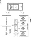
- FIG. 1 illustrates communication system 100 to provide user control over access to WiFi network 120 having geographically-distributed WiFi access systems 121-124.
- Communication system 100 comprises user communication devices 101-103, access network 110, WiFi network 120, and server system 130.
- Server system 130 comprises user interface server 131 and authorization server 132.
- User communication devices 101-103 comprise phones, computers, media players, machine transceivers, or some other WiFi communication equipment.
- User communication devices 101-102 and access network 110 communicate over respective access links 111-112.
- User communication devices 101-103 and WiFi access systems 121-123 communicate over respective WiFi links 113-115.
- Access network 110 and WiFi network 120 communicate with server system 130 over respective network links 116-117.
- user interface server 131 transfers display data to user communication device 101 over access network 110 and links 111 and 116 for presentation to a user.
- the user selects WiFi access systems 121-123 but not access system 124.
- the user also selects a single password for the user-selected WiFi access systems 121-123.
- the display data renders geographic maps that indicate WiFi access systems 121-124 for selection.
- the display data may also include a data collection module to collect the password from the user.
- User communication device 101 transfers user data for delivery to user interface server 131.
- the user data indicates the user-selected WiFi network access systems 121-123, the user-selected password, and possibly other user selections and data.
- User interface server 131 receives and transfers the user data to user authorization server 132.
- Authorization server 132 stores an association between the user-selected WiFi network access systems 121-123 and the user-selected password. Subsequently, user communication device 101 moves near WiFi access system 121 and transfers an access request to WiFi access system 121 using the user-selected password. WiFi access system 121 transfers the access request for delivery to authorization server 132.
- Authorization server 132 receives the access request for access to user-selected WiFi network access system 121 using the user-selected password. Based on the stored association between the user-selected WiFi network access system 121 and the user-selected password, authorization server 132 transfers a positive response for delivery to WiFi network access system 121.
- WiFi network access system 121 then provides WiFi access (typically to the Internet) to wireless communication device 101 over WiFi link 113.
- User wireless communication device 102 could select and use multiple WiFi access systems with a single password in a similar manner.
- wireless communication device 101 is used to select the WiFi access systems and password
- communication device 102 and/or communication device 103 are used to access the selected WiFi access systems with the password.
- a user may have different passwords for different groups of access systems, devices, timeframes, and the like. If desired, the user may also use a given password for only one access system.
- a password could be any sequence of letters, numbers, symbols, or other data.
- additional items are selected by the user responsive to the display data. These additional items may be indicated in the user data, stored in the association, and used in combination to transfer the positive response to the access request.
- the user may specify a user name to use when accessing their selected WiFi network access systems.
- the user specifies a communication device to use when accessing their selected WiFi network access systems.
- the user specifies a timeframe for access to their selected WiFi network access systems.
- user interface server 131 transfers configuration data for delivery to user communication device 101 and/or user communication device 102 over access network 110.
- the configuration data associates broadcast identification signals for the user-selected WiFi network access systems with the user-selected password.
- User communication devices 101-102 use the configuration data to obtain the password from the user and to transfer the access request when in range of one of the selected WiFi network access systems.
- the configuration data includes an access key that is correlated to the broadcast identification signals for the user-selected WiFi network access systems and with the user-selected password.
- the access key is stored in authorization server 132 in association with the user-selected WiFi network access systems.
- User communication device 101 would provide the access key in their access request when in range of one of the selected WiFi network access systems and if the password is provided by the user.
- Authorization server 132 could then return a positive response based on its own stored access key.
- the configuration data indicates a dynamically-changing network key, such as time-of-day, that is correlated to the broadcast identification signals for the user-selected WiFi network access systems and with the user-selected password.
- a dynamically-changing network key such as time-of-day
- user communication device 101 uses the dynamically-changing network key to generate a hash value for their access request.
- authorization server 132 could generate its own hash value based the dynamically-changing network key for comparison to the hash value from the access request. If the comparison indicates the relationship, then authorization server 132 returns the positive response for WiFi access. For example, if the dynamically-changing network key is time-of-day, then both hash values should correlate if calculated within the same timeframe.
- Access network 110 comprises computer and communications equipment that use Wireless Fidelity (WiFi), Long Term Evolution (LTE), Global System for Mobile Communications (GSM), Evolution Data Only (EVDO), Bluetooth, DOCSYS, T1, Ethernet, Internet Protocol (IP), or some other communication protocols - including combinations thereof.
- Server system 130 comprises computer equipment and software that may be implemented in a single platform or may be distributed across multiple platforms.
- Communication links 111-112 and 116-117 might be wireless, optical, metallic, or some other communication media - including combinations thereof.
- Communication links 111-112 and 116-117 may individually comprise multiple parallel connections that utilize different protocols and paths.
- Communication links 111-112 and 116-117 may also include various intermediate networks, systems, and devices.
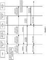
- FIG. 2 illustrates the operation of communication system 100 to provide user control over access to WiFi network 120.
- User interface server 131 transfers display data to user communication device 101 over access network 110, and user communication device 101 graphically presents the resulting display data to the user.
- user communication device might present the display data in the form of geographic maps that indicate WiFi access systems 121-124 for selection.
- the user selects WiFi access systems 121-123.
- the user also specifies a password for user-selected WiFi access systems 121-123.
- User communication device 101 transfers user data over access network 110 to user interface server 131.
- the user data indicates user-selected WiFi network access systems 121-123, the user-selected password, and possibly other user selections and data.
- User interface server 131 transfers the user data to user authorization server 132.
- Authorization server 132 stores an association between the user-selected WiFi network access systems 121-123 and the user-selected password - and typically other pertinent data. Various techniques to store this association are described herein.
- WiFi access system 121 transmits a wireless identification signal for reception by in-range devices, such as an SSID signal, pilot signal, and the like. Subsequently, user communication device 101 detects the identification signal from WiFi access system 121 and prompts the user for a password. The user provides their selected password to user communication device 101, and device 101 transfers an access request to WiFi access system 121 using the user-selected password. Various techniques to use the password are described herein. WiFi access system 121 transfers the access request to authorization server 132.
- Authorization server 132 processes the access request and the stored association between user-selected WiFi network access system 121 and user-selected password to determine that the request should be granted. Authorization server 132 then transfers a positive response to WiFi network access system 121. Based on the positive response, WiFi network access system 121 provides wireless communication device 101 and the user with WiFi network access to some other data system, such as the Internet (not shown).
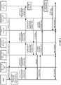
- Figure 3 illustrates the operation of communication system 100 to provide user control over access to WiFi network 120 by allowing user-selection of communication devices.
- User interface server 131 transfers display data to user communication device 101 over access network 110, and user communication device 101 graphically presents the resulting display data to the user.
- the user selects WiFi access systems 121-123 and a password.
- the user also selects communication device 103 to access user-selected WiFi access systems 121-123.
- the user may specify communication device 103 by name, address, number, and the like.
- User interface server 131 may also identify communication device 103 in the display data for selection by the user.
- User communication device 101 transfers user data over access network 110 to user interface server 131.
- the user data indicates user-selected WiFi network access systems 121-123, user-selected communication device 103, the user-selected password, and possibly other information.
- User interface server 131 transfers the user data to user authorization server 132.
- Authorization server 132 stores an association between the user-selected WiFi network access systems 121-123, user-selected communication device 103, the user-selected password, and other data. Various techniques to store this association are described herein.
- WiFi access system 123 transmits its wireless identification signal.
- User communication device 103 detects the identification signal from WiFi access system 123 and prompts the user for a password. The user provides their selected password to user communication device 103, and device 103 transfers an access request to WiFi access system 123 using the user-selected password.
- Various techniques to use the password are described herein.
- WiFi access system 123 transfers the access request to authorization server 132.
- Authorization server 132 processes the access request and the stored association between user-selected WiFi network access system 123, user-selected communication device 103, and the user-selected password to determine that the request should be granted.
- Authorization server 132 then transfers a positive response to WiFi network access system 123.
- WiFi network access system 123 Based on the positive response, WiFi network access system 123 provides user communication device 103 with WiFi network access to another data system, such as the Internet (not shown). Note that other items could be also selected by the user and used for authorization, such as timeframes, security formats, and the like.
- Figure 4 illustrates the operation of communication system 100 to provide user control over access to WiFi network 120 by transferring configuration data to user communication device 101.
- User interface server 131 transfers display data to user communication device 101 over access network 110, and user communication device 101 graphically presents the resulting display data to the user.
- the user selects WiFi access systems 121-123 and a password.
- User communication device 101 transfers user data over access network 110 to user interface server 131.
- the user data indicates user-selected WiFi network access systems 121-123, the user-selected password, and possibly other user selections and data.
- User interface server 131 transfers the user data to user authorization server 132.
- Authorization server 132 stores an association between the user-selected WiFi network access systems 121-123 and one or more access keys for systems 121-123. The stored association may also indicate the user-selected password and other pertinent data.
- user interface server 131 transfers configuration data over access network 110 to user communication device 101.
- the configuration data indicates identification signals (SSIDs and the like) for user-selected WiFi network access systems 121-123.
- the configuration data also indicates the password, the access key, and perhaps other data. Note that user interface server 131 may also transfer the configuration data to other user-selected communication devices.
- User-selected WiFi access system 121 transmits its wireless identification signal, and eventually, user communication device 101 detects this identification signal from WiFi access system 121. Based on the configuration data and the ID signal, user communication device 101 prompts the user for a password. The user provides their selected password to user communication device 101, and device 101 transfers an access request to WiFi access system 121 using the user-selected password. In this example, user communication device 101 uses the password for verification, and if the user-supplied password matches the password from the configuration data, then device 101 transfers the access key to user-selected WiFi access system 121.
- WiFi access system 121 transfers the access request including the access key to authorization server 132.
- Authorization server 132 processes the access request and the stored association between user-selected WiFi network access system 121 and user-supplied access key to determine that the request should be granted.
- Authorization server 132 then transfers a positive response to WiFi network access system 121. Based on the positive response, WiFi network access system 121 provides user communication device 101 and the user with WiFi network access to some other data system, such as the Internet (not shown).
- Figure 5 illustrates the operation of communication system 100 to provide user control over access to WiFi network 120 by using dynamic access keys.
- User interface server 131 transfers display data to user communication device 101 over access network 110, and user communication device 101 graphically presents the resulting display data to the user.
- the user selects WiFi access systems 121-123, a password, and user communication device 102.
- User communication device 101 transfers user data over access network 110 to user interface server 131.
- the user data indicates user-selected WiFi network access systems 121-123, user communication device 102, the user-selected password, and possibly other data.
- User interface server 131 transfers the user data to user authorization server 132.
- Authorization server 132 stores an association between the user-selected WiFi network access systems 121-123 and a secret code used to generate the dynamic key. The stored association may also indicate the user-selected password and other pertinent data.
- user interface server 131 transfers configuration data over access network 110 to user communication device 102.
- the configuration data indicates identification signals for user-selected WiFi network access systems 121-123.
- the configuration data also indicates the password, secret code, dynamic key instructions, and perhaps other data. Note that user interface server 131 may also transfer the configuration data to other user-selected communication devices.
- User-selected WiFi access system 122 transmits its wireless identification signal, and eventually, user communication device 102 detects this identification signal from WiFi access system 122. Based on the configuration data and the ID signal, user communication device 102 prompts the user for a password. The user provides their selected password to user communication device 102, and device 102 transfers an access request to WiFi access system 122 using the user-selected password.
- user communication device 102 uses the password for verification, and if the user-supplied password matches the password from the configuration data, then device 102 generates and transfers a dynamic access key to user-selected WiFi access system 122.
- the dynamic key is a mathematical hash between the secret code from the configuration data and dynamically changing network data.
- the secret code could be mathematically combined with the current time-of-day to generate the dynamic access key.
- WiFi access system 122 transfers the access request including the dynamic access key to authorization server 132.
- Authorization server 132 processes the access request and the stored association (the secret code) to generate the dynamic access key in a similar manner to device 102. If the two dynamic access keys correlate, then the access request should be granted. Note that the correlation may not require a strict match. For example, if time of day is used for the dynamic key, then two keys generated around the same time would have a detectable mathematical relationship and would correlate. Various other dynamic key techniques could be used in a similar manner.
- Authorization server 132 then transfers a positive response to WiFi network access system 122. Based on the positive response, WiFi network access system 122 provides user communication device 102 and the user with WiFi network access to some other data system, such as the Internet (not shown).
- Figure 6 illustrates communication device display 600 that renders a geographic map for a user to select WiFi network access systems 601-604 and specify passwords.
- the geographic map is depicted by a simple grid on Figure 6 . Note that navigation controls would be provided on the map, but they are not depicted for clarity.
- the user has selected WiFi access systems 602-603 as indicated by the frame around systems 602-603.
- Text boxes are associated with the selected WiFi access systems 602-603 and provide a mechanism for the user to specify passwords, user names, user devices, security settings, and the like.
- the text boxes also provide access system information, such as SSIDs, location, and possibly other data.
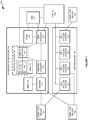
- FIG. 7 illustrates LTE/WiFi communication system 700 to provide user control over access to WiFi network 720 having geographically-distributed WiFi access systems 721-724.
- LTE/WiFi communication system 700 comprises user communication devices 701-703, wireless LTE network 710, WiFi network 720, IP Multimedia Subsystem (IMS) 717, and IP networks 718.
- Wireless LTE network 710 includes eNodeB 711, serving gateway 712, Packet Data Network (PDN) gateway 713, Mobility Management Entity (MME) 714, Home Subscriber Server (HSS) 715, and Policy Charging and Rules Function (PCRF) 716.
- PDN Packet Data Network
- MME Mobility Management Entity
- HSS Home Subscriber Server
- PCRF Policy Charging and Rules Function
- Wireless LTE network 710 also includes server system 730 that comprises user interface server 731 and authorization server 732.
- User interface server 731 and authorization server 732 operate like servers 131-132 described above.
- the authorization server 732 is hosted by or integrated within HSS 715.
- wireless LTE network 710 operates like access network 110 described above.
- wireless LTE network 710 transfers the display data, receives user-selections, transfers configuration data, and provides WiFi authorization as described above.
- the user may operate one of communication devices 701-703 to access user interface server 731 and select WiFi access systems 721-722 and 724, a user name, a password, user devices 701-703, timeframes, and the like.
- WiFi access systems 721-722 and 724 When one of the selected user communication devices 701-703 is proximate to one of the selected WiFi access systems 721-722 and 724, then the user device will interact with the proximate WiFi access system as described above.
- the proximate WiFi access system will transfer access requests to authorization server 732 in HSS 715 - typically through various proxies and interfaces.
- Authorization server 732 in HSS 715 transfers positive responses as described above.
- FIG. 8 illustrates WiFi communication system 800 to provide user control over access to WiFi network 820 having geographically-distributed WiFi access systems 821-824.
- WiFi communication system 800 comprises user communication devices 801-803, IP access network 810, IP networks 818, and server system 830.
- Server system 830 resides in the core of a nationwide wireless communication network.
- Server system 830 comprises user interface server 831 and authorization server 832.
- User interface server 831 and authorization server 832 and operate like servers 131-132 described above.
- server system 830 transfers the display data, receives user-selections, transfers configuration data, and provides WiFi authorization as described above.
- the user may operate one of communication devices 801-803 to access user interface server 831 and select WiFi access systems 821-822 and 824, a user name, a password, user devices 801-803, timeframes, and the like.
- WiFi access systems 821-822 and 824 select WiFi access systems 821-822 and 824, a user name, a password, user devices 801-803, timeframes, and the like.
- the user device When one of the selected user communication devices 801-803 is proximate to one of the selected WiFi access systems 821-822 and 824, then the user device will interact with the proximate WiFi access system as described above.
- the proximate WiFi access system will transfer access requests to authorization server 832.
- Authorization server 832 transfers positive responses as described above.
- portions of the server systems described herein could be integrated into the authorization systems of other networks.
- the AAA system in a 2G or 3G network could host the user interface server and/or the authorization servers described herein.
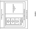
- FIG. 9 illustrates server system 900 to provide user control over access to WiFi networks.
- Server system 900 is an example of the server system 130, although system 130 may use alternative configurations and operations.
- Server system 900 comprises communication transceivers 901 and processing system 903.
- Processing system 903 comprises micro-processing circuitry 911 and memory 912.
- Memory 912 stores software 913.
- Server system 900 may be integrated into a single platform or may be distributed across multiple diverse computer and communication systems. Some conventional aspects of server system 900 are omitted for clarity, such as power supplies, enclosures, and the like.
- Communication transceivers 901 comprise communication components, such as ports, circuitry, memory, software, and the like. Communication transceivers 901 typically utilize Ethernet, Internet, or some other networking protocol - including combinations thereof.
- Micro-processor circuitry 911 comprises circuit boards that hold integrated circuitry and associated electronics.
- Memory 912 comprises non-transitory, computer-readable, data storage media, such as flash drives, disc drives, and the like.
- Software 913 comprises computer-readable instructions that control the operation of micro-processor circuitry 911 when executed.
- Software 913 includes modules 921-923 and may also include operating systems, applications, utilities, databases, and the like.
- Micro-processor circuitry 911 and memory 912 may be integrated into a single computer system or may be distributed across multiple computer systems.
- user module 921 When executed by circuitry 911, user module 921 directs circuitry 911 to interact with user devices to enable the user to select access systems, passwords, and the like. User module 921 also directs circuitry 911 to transfer configuration data in some examples.
- database module 922 When executed by circuitry 911, database module 922 directs circuitry 911 to stores the associations as described above.
- authorization module 923 When executed by circuitry 911, authorization module 923 directs circuitry 911 to provide positive or negative responses to WiFi access requests based on the stored associations.
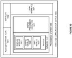
- FIG. 10 illustrates wireless communication device 1000 to provide user control over access to WiFi networks.
- Wireless communication device 1000 is an example of user communication devices 101-103, although devices 101-103 may use alternative configurations and operations.
- Wireless communication device 1000 comprises access network transceiver 1001, network transceiver 1002, processing system 1003, and user interface 1004.
- Processing system 1003 comprises micro-processing circuitry 1011 and memory 1012.
- Memory 1012 stores software 1013.
- Some conventional aspects of wireless communication device 1000 are omitted for clarity, such as power supplies, enclosures, and the like.
- Wireless communication device 1000 may be integrated into other systems or devices.
- Access network transceiver 1001 and WiFi transceiver 1002 each comprise communication components, such as circuitry, memory, software, antennas, amplifiers, filters, modulators, signal processors, and the like.
- the radio communications include multiple transceiver sub-systems for near-field, local network, and wide-area network data communications.
- Access network transceiver 1001 exchanges user data and configuration data as described above.
- WiFi network transceiver 1002 detects WiFi identification signals, transfers WiFi access requests, and provides WiFi network access.
- User interface 1004 includes components to interact with a human operator, such as a touch display, speaker, microphone, camera, buttons, and switches.
- User interface 1004 displays maps, text boxes, user prompts and the like.
- a touch display in user interface 1004 receives the user instructions that trigger the actions described herein.
- Micro-processor circuitry 1011 comprises one or more circuit boards that hold integrated circuit chips and associated electronics.
- Memory 1012 comprises non-transitory data storage media, such as flash drives, disc drives, and the like.
- Software 1013 comprises computer-readable instructions that control the operation of micro-processor circuitry 1011 when executed.
- Software 1013 includes modules 1021-1023 and may also include additional operating systems, applications, utilities, databases, and the like.
- display module 1021 directs circuitry 1011 to display maps, text boxes, and the like to receive user selections.
- configuration module 1022 direct circuitry 1011 to receive and store configuration data as described herein.
- WiFi module 1023 directs circuitry 1011 to prompt for passwords and transfer access requests as described herein.
Landscapes
- Engineering & Computer Science (AREA)
- Computer Security & Cryptography (AREA)
- Computer Networks & Wireless Communication (AREA)
- Signal Processing (AREA)
- Computer Hardware Design (AREA)
- Computing Systems (AREA)
- General Engineering & Computer Science (AREA)
- Mobile Radio Communication Systems (AREA)
Description
- Wireless Fidelity (WiFi) is a popular wireless protocol to obtain network access - often to the Internet. Typically, a WiFi access point broadcasts a Service Set Identification (SSID) that is detected by user devices. The user devices typically respond to the SSID with an access code that is pre-stored in the WiFi access point. The WiFi access point provides network access if the user-provided access code matches the pre-stored access code. The user typically manages multiple access codes for the various WiFi access points that they use. Unfortunately, these WiFi access points are not used to provide effective and efficient user control over WiFi network access.
- Other wireless networks also include user authorization systems that control network access. For example, 3G networks may have an Authentication, Authorization, and Accounting (AAA) system, and 4G networks may have a Home Subscriber Server (HSS). These other wireless networks also provide network access to user devices. Unfortunately, the other wireless networks are not used to provide effective and efficient user control over WiFi network access.
- In particular, WiFi access points and these other wireless networks are not effectively used in an integrated manner to provide efficient user control over WiFi network access.
- Document
EP2200223 discloses a method for performing roaming in WLAN by only managing a common/single authentication information (password&login) to be used for a plurality of AP. When requesting access to a WiFi, the UE sends these credentials to the AP, which then forwards it to the authentication server which decides when to approve UE's access to said AP. - The present invention relates to a method and a system as set forth in claims 1 and 4. Further embodiments are set forth in the dependent claims.
-
-
Figure 1 illustrates a communication system to provide user control over access to a WiFi network having geographically-distributed WiFi access systems. -
Figure 2 illustrates the operation of a communication system to provide user control over access to a WiFi network having geographically-distributed WiFi access systems. -
Figure 3 illustrates the operation of a communication system to provide user control over access to a WiFi network having geographically-distributed WiFi access systems by allowing user-selection of communication devices. -
Figure 4 illustrates the operation of a communication system to provide user control over access to a WiFi network having geographically-distributed WiFi access systems by transferring configuration data to a user communication device. -
Figure 5 illustrates the operation of a communication system to provide user control over access to a WiFi network having geographically-distributed WiFi access systems by using dynamic access keys. -
Figure 6 illustrates a communication device display that renders a geographic map for a user to select WiFi network access systems and specify passwords. -
Figure 7 illustrates a wireless Long Term Evolution (LTE) network to provide user control over access to a WiFi network having geographically-distributed WiFi access systems. -
Figure 8 illustrates an WiFi system to provide user control over access to a WiFi network having geographically-distributed WiFi access systems. -
Figure 9 illustrates a server system to provide user control over access to WiFi networks. -
Figure 10 illustrates wireless communication device to provide user control over access to WiFi networks. -
Figure 1 illustratescommunication system 100 to provide user control over access toWiFi network 120 having geographically-distributed WiFi access systems 121-124.Communication system 100 comprises user communication devices 101-103,access network 110,WiFi network 120, andserver system 130.Server system 130 comprisesuser interface server 131 andauthorization server 132. - User communication devices 101-103 comprise phones, computers, media players, machine transceivers, or some other WiFi communication equipment. User communication devices 101-102 and
access network 110 communicate over respective access links 111-112. User communication devices 101-103 and WiFi access systems 121-123 communicate over respective WiFi links 113-115.Access network 110 andWiFi network 120 communicate withserver system 130 over respective network links 116-117. - In operation,
user interface server 131 transfers display data touser communication device 101 overaccess network 110 andlinks system 124. The user also selects a single password for the user-selected WiFi access systems 121-123. In some examples, the display data renders geographic maps that indicate WiFi access systems 121-124 for selection. The display data may also include a data collection module to collect the password from the user. -
User communication device 101 transfers user data for delivery touser interface server 131. The user data indicates the user-selected WiFi network access systems 121-123, the user-selected password, and possibly other user selections and data.User interface server 131 receives and transfers the user data touser authorization server 132. -
Authorization server 132 stores an association between the user-selected WiFi network access systems 121-123 and the user-selected password. Subsequently,user communication device 101 moves nearWiFi access system 121 and transfers an access request toWiFi access system 121 using the user-selected password.WiFi access system 121 transfers the access request for delivery toauthorization server 132. -
Authorization server 132 receives the access request for access to user-selected WiFinetwork access system 121 using the user-selected password. Based on the stored association between the user-selected WiFinetwork access system 121 and the user-selected password,authorization server 132 transfers a positive response for delivery to WiFinetwork access system 121. WiFinetwork access system 121 then provides WiFi access (typically to the Internet) towireless communication device 101 overWiFi link 113. - User
wireless communication device 102 could select and use multiple WiFi access systems with a single password in a similar manner. In some examples,wireless communication device 101 is used to select the WiFi access systems and password, whilecommunication device 102 and/orcommunication device 103 are used to access the selected WiFi access systems with the password. Also note that a user may have different passwords for different groups of access systems, devices, timeframes, and the like. If desired, the user may also use a given password for only one access system. Note that a password could be any sequence of letters, numbers, symbols, or other data. - In some examples, additional items are selected by the user responsive to the display data. These additional items may be indicated in the user data, stored in the association, and used in combination to transfer the positive response to the access request. For example, the user may specify a user name to use when accessing their selected WiFi network access systems. In other examples, the user specifies a communication device to use when accessing their selected WiFi network access systems. In yet other examples, the user specifies a timeframe for access to their selected WiFi network access systems.
- In some examples,
user interface server 131 transfers configuration data for delivery touser communication device 101 and/oruser communication device 102 overaccess network 110. The configuration data associates broadcast identification signals for the user-selected WiFi network access systems with the user-selected password. User communication devices 101-102 use the configuration data to obtain the password from the user and to transfer the access request when in range of one of the selected WiFi network access systems. - In some examples, the configuration data includes an access key that is correlated to the broadcast identification signals for the user-selected WiFi network access systems and with the user-selected password. The access key is stored in
authorization server 132 in association with the user-selected WiFi network access systems.User communication device 101 would provide the access key in their access request when in range of one of the selected WiFi network access systems and if the password is provided by the user.Authorization server 132 could then return a positive response based on its own stored access key. - In some examples, the configuration data indicates a dynamically-changing network key, such as time-of-day, that is correlated to the broadcast identification signals for the user-selected WiFi network access systems and with the user-selected password. When in range of one of the selected WiFi network access systems and if the password is provided by the user,
user communication device 101 uses the dynamically-changing network key to generate a hash value for their access request. In response to the access request,authorization server 132 could generate its own hash value based the dynamically-changing network key for comparison to the hash value from the access request. If the comparison indicates the relationship, thenauthorization server 132 returns the positive response for WiFi access. For example, if the dynamically-changing network key is time-of-day, then both hash values should correlate if calculated within the same timeframe. -
Access network 110 comprises computer and communications equipment that use Wireless Fidelity (WiFi), Long Term Evolution (LTE), Global System for Mobile Communications (GSM), Evolution Data Only (EVDO), Bluetooth, DOCSYS, T1, Ethernet, Internet Protocol (IP), or some other communication protocols - including combinations thereof.Server system 130 comprises computer equipment and software that may be implemented in a single platform or may be distributed across multiple platforms. Communication links 111-112 and 116-117 might be wireless, optical, metallic, or some other communication media - including combinations thereof. Communication links 111-112 and 116-117 may individually comprise multiple parallel connections that utilize different protocols and paths. Communication links 111-112 and 116-117 may also include various intermediate networks, systems, and devices. -
Figure 2 illustrates the operation ofcommunication system 100 to provide user control over access toWiFi network 120.User interface server 131 transfers display data touser communication device 101 overaccess network 110, anduser communication device 101 graphically presents the resulting display data to the user. For example, user communication device might present the display data in the form of geographic maps that indicate WiFi access systems 121-124 for selection. In response to the display data, the user selects WiFi access systems 121-123. The user also specifies a password for user-selected WiFi access systems 121-123. -
User communication device 101 transfers user data overaccess network 110 touser interface server 131. The user data indicates user-selected WiFi network access systems 121-123, the user-selected password, and possibly other user selections and data.User interface server 131 transfers the user data touser authorization server 132.Authorization server 132 stores an association between the user-selected WiFi network access systems 121-123 and the user-selected password - and typically other pertinent data. Various techniques to store this association are described herein. -
WiFi access system 121 transmits a wireless identification signal for reception by in-range devices, such as an SSID signal, pilot signal, and the like. Subsequently,user communication device 101 detects the identification signal fromWiFi access system 121 and prompts the user for a password. The user provides their selected password touser communication device 101, anddevice 101 transfers an access request toWiFi access system 121 using the user-selected password. Various techniques to use the password are described herein.WiFi access system 121 transfers the access request toauthorization server 132. -
Authorization server 132 processes the access request and the stored association between user-selected WiFinetwork access system 121 and user-selected password to determine that the request should be granted.Authorization server 132 then transfers a positive response to WiFinetwork access system 121. Based on the positive response, WiFinetwork access system 121 provideswireless communication device 101 and the user with WiFi network access to some other data system, such as the Internet (not shown). -
Figure 3 illustrates the operation ofcommunication system 100 to provide user control over access toWiFi network 120 by allowing user-selection of communication devices.User interface server 131 transfers display data touser communication device 101 overaccess network 110, anduser communication device 101 graphically presents the resulting display data to the user. In response to the display data, the user selects WiFi access systems 121-123 and a password. In this example, the user also selectscommunication device 103 to access user-selected WiFi access systems 121-123. The user may specifycommunication device 103 by name, address, number, and the like.User interface server 131 may also identifycommunication device 103 in the display data for selection by the user. -
User communication device 101 transfers user data overaccess network 110 touser interface server 131. The user data indicates user-selected WiFi network access systems 121-123, user-selectedcommunication device 103, the user-selected password, and possibly other information.User interface server 131 transfers the user data touser authorization server 132.Authorization server 132 stores an association between the user-selected WiFi network access systems 121-123, user-selectedcommunication device 103, the user-selected password, and other data. Various techniques to store this association are described herein. -
WiFi access system 123 transmits its wireless identification signal.User communication device 103 detects the identification signal fromWiFi access system 123 and prompts the user for a password. The user provides their selected password touser communication device 103, anddevice 103 transfers an access request toWiFi access system 123 using the user-selected password. Various techniques to use the password are described herein. -
WiFi access system 123 transfers the access request toauthorization server 132.Authorization server 132 processes the access request and the stored association between user-selected WiFinetwork access system 123, user-selectedcommunication device 103, and the user-selected password to determine that the request should be granted.Authorization server 132 then transfers a positive response to WiFinetwork access system 123. Based on the positive response, WiFinetwork access system 123 providesuser communication device 103 with WiFi network access to another data system, such as the Internet (not shown). Note that other items could be also selected by the user and used for authorization, such as timeframes, security formats, and the like. -
Figure 4 illustrates the operation ofcommunication system 100 to provide user control over access toWiFi network 120 by transferring configuration data touser communication device 101.User interface server 131 transfers display data touser communication device 101 overaccess network 110, anduser communication device 101 graphically presents the resulting display data to the user. In response to the display data, the user selects WiFi access systems 121-123 and a password. -
User communication device 101 transfers user data overaccess network 110 touser interface server 131. The user data indicates user-selected WiFi network access systems 121-123, the user-selected password, and possibly other user selections and data.User interface server 131 transfers the user data touser authorization server 132.Authorization server 132 stores an association between the user-selected WiFi network access systems 121-123 and one or more access keys for systems 121-123. The stored association may also indicate the user-selected password and other pertinent data. - Responsive to the user-selections,
user interface server 131 transfers configuration data overaccess network 110 touser communication device 101. The configuration data indicates identification signals (SSIDs and the like) for user-selected WiFi network access systems 121-123. The configuration data also indicates the password, the access key, and perhaps other data. Note thatuser interface server 131 may also transfer the configuration data to other user-selected communication devices. - User-selected
WiFi access system 121 transmits its wireless identification signal, and eventually,user communication device 101 detects this identification signal fromWiFi access system 121. Based on the configuration data and the ID signal,user communication device 101 prompts the user for a password. The user provides their selected password touser communication device 101, anddevice 101 transfers an access request toWiFi access system 121 using the user-selected password. In this example,user communication device 101 uses the password for verification, and if the user-supplied password matches the password from the configuration data, thendevice 101 transfers the access key to user-selectedWiFi access system 121. -
WiFi access system 121 transfers the access request including the access key toauthorization server 132.Authorization server 132 processes the access request and the stored association between user-selected WiFinetwork access system 121 and user-supplied access key to determine that the request should be granted.Authorization server 132 then transfers a positive response to WiFinetwork access system 121. Based on the positive response, WiFinetwork access system 121 providesuser communication device 101 and the user with WiFi network access to some other data system, such as the Internet (not shown). -
Figure 5 illustrates the operation ofcommunication system 100 to provide user control over access toWiFi network 120 by using dynamic access keys.User interface server 131 transfers display data touser communication device 101 overaccess network 110, anduser communication device 101 graphically presents the resulting display data to the user. In response to the display data, the user selects WiFi access systems 121-123, a password, anduser communication device 102. -
User communication device 101 transfers user data overaccess network 110 touser interface server 131. The user data indicates user-selected WiFi network access systems 121-123,user communication device 102, the user-selected password, and possibly other data.User interface server 131 transfers the user data touser authorization server 132.Authorization server 132 stores an association between the user-selected WiFi network access systems 121-123 and a secret code used to generate the dynamic key. The stored association may also indicate the user-selected password and other pertinent data. - Responsive to the user-selections,
user interface server 131 transfers configuration data overaccess network 110 touser communication device 102. The configuration data indicates identification signals for user-selected WiFi network access systems 121-123. The configuration data also indicates the password, secret code, dynamic key instructions, and perhaps other data. Note thatuser interface server 131 may also transfer the configuration data to other user-selected communication devices. - User-selected
WiFi access system 122 transmits its wireless identification signal, and eventually,user communication device 102 detects this identification signal fromWiFi access system 122. Based on the configuration data and the ID signal,user communication device 102 prompts the user for a password. The user provides their selected password touser communication device 102, anddevice 102 transfers an access request toWiFi access system 122 using the user-selected password. - In this example,
user communication device 102 uses the password for verification, and if the user-supplied password matches the password from the configuration data, thendevice 102 generates and transfers a dynamic access key to user-selectedWiFi access system 122. In this example, the dynamic key is a mathematical hash between the secret code from the configuration data and dynamically changing network data. For example, the secret code could be mathematically combined with the current time-of-day to generate the dynamic access key. -
WiFi access system 122 transfers the access request including the dynamic access key toauthorization server 132.Authorization server 132 processes the access request and the stored association (the secret code) to generate the dynamic access key in a similar manner todevice 102. If the two dynamic access keys correlate, then the access request should be granted. Note that the correlation may not require a strict match. For example, if time of day is used for the dynamic key, then two keys generated around the same time would have a detectable mathematical relationship and would correlate. Various other dynamic key techniques could be used in a similar manner. -
Authorization server 132 then transfers a positive response to WiFinetwork access system 122. Based on the positive response, WiFinetwork access system 122 providesuser communication device 102 and the user with WiFi network access to some other data system, such as the Internet (not shown). -
Figure 6 illustratescommunication device display 600 that renders a geographic map for a user to select WiFi network access systems 601-604 and specify passwords. For clarity, the geographic map is depicted by a simple grid onFigure 6 . Note that navigation controls would be provided on the map, but they are not depicted for clarity. In this example, the user has selected WiFi access systems 602-603 as indicated by the frame around systems 602-603. Text boxes are associated with the selected WiFi access systems 602-603 and provide a mechanism for the user to specify passwords, user names, user devices, security settings, and the like. The text boxes also provide access system information, such as SSIDs, location, and possibly other data. -
Figure 7 illustrates LTE/WiFi communication system 700 to provide user control over access toWiFi network 720 having geographically-distributed WiFi access systems 721-724. LTE/WiFi communication system 700 comprises user communication devices 701-703,wireless LTE network 710,WiFi network 720, IP Multimedia Subsystem (IMS) 717, andIP networks 718.Wireless LTE network 710 includeseNodeB 711, servinggateway 712, Packet Data Network (PDN)gateway 713, Mobility Management Entity (MME) 714, Home Subscriber Server (HSS) 715, and Policy Charging and Rules Function (PCRF) 716. -
Wireless LTE network 710 also includesserver system 730 that comprisesuser interface server 731 andauthorization server 732.User interface server 731 andauthorization server 732 operate like servers 131-132 described above. Note that theauthorization server 732 is hosted by or integrated withinHSS 715. In a like manner,wireless LTE network 710 operates likeaccess network 110 described above. Thus,wireless LTE network 710 transfers the display data, receives user-selections, transfers configuration data, and provides WiFi authorization as described above. - For example, the user may operate one of communication devices 701-703 to access
user interface server 731 and select WiFi access systems 721-722 and 724, a user name, a password, user devices 701-703, timeframes, and the like. When one of the selected user communication devices 701-703 is proximate to one of the selected WiFi access systems 721-722 and 724, then the user device will interact with the proximate WiFi access system as described above. The proximate WiFi access system will transfer access requests toauthorization server 732 in HSS 715 - typically through various proxies and interfaces.Authorization server 732 inHSS 715 transfers positive responses as described above. -
Figure 8 illustratesWiFi communication system 800 to provide user control over access toWiFi network 820 having geographically-distributed WiFi access systems 821-824.WiFi communication system 800 comprises user communication devices 801-803,IP access network 810,IP networks 818, andserver system 830.Server system 830 resides in the core of a nationwide wireless communication network. -
Server system 830 comprisesuser interface server 831 andauthorization server 832.User interface server 831 andauthorization server 832 and operate like servers 131-132 described above. Thus,server system 830 transfers the display data, receives user-selections, transfers configuration data, and provides WiFi authorization as described above. - For example, the user may operate one of communication devices 801-803 to access
user interface server 831 and select WiFi access systems 821-822 and 824, a user name, a password, user devices 801-803, timeframes, and the like. When one of the selected user communication devices 801-803 is proximate to one of the selected WiFi access systems 821-822 and 824, then the user device will interact with the proximate WiFi access system as described above. The proximate WiFi access system will transfer access requests toauthorization server 832.Authorization server 832 transfers positive responses as described above. - In other examples, portions of the server systems described herein could be integrated into the authorization systems of other networks. For example, the AAA system in a 2G or 3G network could host the user interface server and/or the authorization servers described herein.
-
Figure 9 illustratesserver system 900 to provide user control over access to WiFi networks.Server system 900 is an example of theserver system 130, althoughsystem 130 may use alternative configurations and operations.Server system 900 comprisescommunication transceivers 901 andprocessing system 903.Processing system 903 comprisesmicro-processing circuitry 911 andmemory 912.Memory 912stores software 913.Server system 900 may be integrated into a single platform or may be distributed across multiple diverse computer and communication systems. Some conventional aspects ofserver system 900 are omitted for clarity, such as power supplies, enclosures, and the like. -
Communication transceivers 901 comprise communication components, such as ports, circuitry, memory, software, and the like.Communication transceivers 901 typically utilize Ethernet, Internet, or some other networking protocol - including combinations thereof. -
Micro-processor circuitry 911 comprises circuit boards that hold integrated circuitry and associated electronics.Memory 912 comprises non-transitory, computer-readable, data storage media, such as flash drives, disc drives, and the like.Software 913 comprises computer-readable instructions that control the operation ofmicro-processor circuitry 911 when executed.Software 913 includes modules 921-923 and may also include operating systems, applications, utilities, databases, and the like.Micro-processor circuitry 911 andmemory 912 may be integrated into a single computer system or may be distributed across multiple computer systems. - When executed by
circuitry 911,user module 921 directscircuitry 911 to interact with user devices to enable the user to select access systems, passwords, and the like.User module 921 also directscircuitry 911 to transfer configuration data in some examples. When executed bycircuitry 911,database module 922 directscircuitry 911 to stores the associations as described above. When executed bycircuitry 911,authorization module 923 directscircuitry 911 to provide positive or negative responses to WiFi access requests based on the stored associations. -
Figure 10 illustrateswireless communication device 1000 to provide user control over access to WiFi networks.Wireless communication device 1000 is an example of user communication devices 101-103, although devices 101-103 may use alternative configurations and operations.Wireless communication device 1000 comprisesaccess network transceiver 1001,network transceiver 1002,processing system 1003, anduser interface 1004.Processing system 1003 comprisesmicro-processing circuitry 1011 andmemory 1012.Memory 1012stores software 1013. Some conventional aspects ofwireless communication device 1000 are omitted for clarity, such as power supplies, enclosures, and the like.Wireless communication device 1000 may be integrated into other systems or devices. -
Access network transceiver 1001 andWiFi transceiver 1002 each comprise communication components, such as circuitry, memory, software, antennas, amplifiers, filters, modulators, signal processors, and the like. In some examples, the radio communications include multiple transceiver sub-systems for near-field, local network, and wide-area network data communications.Access network transceiver 1001 exchanges user data and configuration data as described above.WiFi network transceiver 1002 detects WiFi identification signals, transfers WiFi access requests, and provides WiFi network access. -
User interface 1004 includes components to interact with a human operator, such as a touch display, speaker, microphone, camera, buttons, and switches.User interface 1004 displays maps, text boxes, user prompts and the like. Typically a touch display inuser interface 1004 receives the user instructions that trigger the actions described herein. -
Micro-processor circuitry 1011 comprises one or more circuit boards that hold integrated circuit chips and associated electronics.Memory 1012 comprises non-transitory data storage media, such as flash drives, disc drives, and the like.Software 1013 comprises computer-readable instructions that control the operation ofmicro-processor circuitry 1011 when executed.Software 1013 includes modules 1021-1023 and may also include additional operating systems, applications, utilities, databases, and the like. - When executed by
circuitry 1011,display module 1021 directscircuitry 1011 to display maps, text boxes, and the like to receive user selections. When executed bycircuitry 1011,configuration module 1022direct circuitry 1011 to receive and store configuration data as described herein. When executed bycircuitry 1011,WiFi module 1023 directscircuitry 1011 to prompt for passwords and transfer access requests as described herein. - The above description and associated figures teach the best mode of the invention. The following claims specify the scope of the invention. Note that some aspects of the best mode may not fall within the scope of the invention as specified by the claims. Those skilled in the art will appreciate that the features described above can be combined in various ways to form multiple variations of the invention. As a result, the invention is not limited to the specific embodiments described above, but only by the following claims.
Claims (6)
- A method of operating a system (100) comprising a user communication device (101 - 103) and a server system (130) to control access to a Wireless Fidelity (WiFi) network (120) that comprises a plurality of geographically-distributed WiFi access systems (121 - 124), the method comprising:transferring display data from the server system (130) for presentation by the user communication device (101 - 103), and responsively receiving into the user communication device (101 - 103) user selections of more than one of the geographically-distributed WiFi access systems (121 - 124), and a single user-selected name and a single user-selected password to use when accessing the multiple user-selected WiFi access systems (121 - 124),receiving, from the user communication device (101 - 103), user data into the server system (130) that indicates the multiple user-selected WiFi network access systems (121 - 124), the single user-selected name, and the single user-selected password; andstoring an association between the multiple user-selected WiFi network access systems (121 - 124), the single user-selected name, and the single user-selected password;receiving, from the user communication device (101 - 103), an access request comprising the single user-selected name and the single user-selected password into the server system (130) for access to one of the multiple user-selected WiFi network access systems (121 - 124) using the single user-selected name and the single user-selected password;processing the access request and the stored association between the multiple user-selected WiFi network access systems (121 - 124), the single user-selected name, and the single user-selected password to determine whether access to the multiple user-selected WiFi network access systems (121 - 124) should be granted; andtransferring a positive response to the access request from the server system (130) based on a determination that access should be granted.
- The method of claim 1 wherein:the user communication device (101 - 103) is used to select a communication device (101 - 103) for accessing the multiple user-selected WiFi access systems (121 - 124) responsive to the display data;receiving the user data comprises receiving the user data indicating the user-selected communication device (101 - 103);storing the association comprises storing the association between the multiple user-selected WiFi network access systems (121 - 124), the single user-selected name, the single user-selected password, and the user-selected communication device (101 - 103);receiving the access request comprises receiving the access request indicating the user-selected communication device (101 - 103); andprocessing comprises processing the access request and the stored association between the multiple user-selected WiFi network access systems (121 - 124), the single user-selected name, the single user-selected password, and the user-selected communication device (101 - 103).
- The method of claim 2 further comprising transferring configuration data for delivery to the user-selected communication device (101 - 103), wherein the configuration data associates broadcast identification signals for the user-selected WiFi network access systems (121 - 124) with the single user-selected password.
- A system (100) comprising a user communication device (101 - 103) and a server system (130) to control access to a Wireless Fidelity (WiFi) network (120) that comprises a plurality of geographically-distributed WiFi access systems (121 - 124), the server system (130) comprising:a user interface server (131) configuredto transfer display data from the server system (130) for presentation by the user communication device (101 - 103), wherein the user communication device (101 - 103) is configured to receive user selections of more than one of the geographically-distributed WiFi access systems (121 - 124) and a single user-selected name for the multiple user-selected WiFi access systems (121 - 124), and a single password for the multiple user-selected WiFi access systems (121 - 124) in response to the display data, the user communication device (101 - 103) being further configured to transfer user data to the user interface server (131; the user interface server (131) being further configuredto receive the user data into the server system (130), wherein the user data indicates the user-selected WiFi network access systems (121 - 124), the single user-selected name, and the single user-selected password; andan authorization server (132) operationally coupled to the user interface server (131) and configuredto store an association between the multiple user-selected WiFi network access systems (121 - 124), the single user-selected name, and the single user-selected password,the user communication device (101 - 103) being further configured to send an access request comprising the user-selected name and the single user-selected password,the authorization server (132) being further configured to receive the access request into the server system (130) for access to one of the user-selected WiFi network access systems (121 - 124) using the single user-selected name and the single user-selected password,to process the access request and the stored association between the multiple user-selected WiFi network access systems (121 - 124), the single user-selected name, and the single user-selected password to determine whether access to the multiple user-selected WiFi network access systems (121 - 124) should be granted; andto transfer a positive response to the access request from the server system (130) based on a determination that access should be granted.
- The system (100) of claim 4 wherein:the user communication device (101 - 103) is further configured to be used to select a communication device (101 - 103) for accessing the multiple user-selected WiFi access systems (121 - 124) responsive to the display data;the user interface server (131) is configured to receive data indicating the user-selected communication device (101 - 103);the authorization server (132) is configuredto store the association between the multiple user-selected WiFi network access systems (121 - 124), the single user-selected name, the single user-selected password, and the user-selected communication device (101 - 103); and the authorization server (132) is configuredto receive the access request indicating the user-selected communication device (101 - 103) and process the access request and the stored association between the multiple user-selected WiFi network access systems (121 - 124), the user-selected communication device (101 - 103), and the single user-selected user name.
- The system (100) of claim 5 wherein the user interface server (131) is configured to transfer configuration data for delivery to the user-selected communication device (101 - 103) wherein the configuration data associates broadcast identification signals for the multiple user-selected WiFi network access systems (121 - 124) with the single user-selected password.
Applications Claiming Priority (2)
| Application Number | Priority Date | Filing Date | Title |
|---|---|---|---|
| US13/552,749 US9344452B2 (en) | 2012-07-19 | 2012-07-19 | User control over WiFi network access |
| PCT/US2013/050635 WO2014014880A1 (en) | 2012-07-19 | 2013-07-16 | User control over wifi network access |
Publications (2)
| Publication Number | Publication Date |
|---|---|
| EP2875663A1 EP2875663A1 (en) | 2015-05-27 |
| EP2875663B1 true EP2875663B1 (en) | 2018-01-10 |
Family
ID=48875786
Family Applications (1)
| Application Number | Title | Priority Date | Filing Date |
|---|---|---|---|
| EP13742116.0A Active EP2875663B1 (en) | 2012-07-19 | 2013-07-16 | User control over wifi network access |
Country Status (4)
| Country | Link |
|---|---|
| US (2) | US9344452B2 (en) |
| EP (1) | EP2875663B1 (en) |
| CA (1) | CA2879117C (en) |
| WO (1) | WO2014014880A1 (en) |
Families Citing this family (27)
| Publication number | Priority date | Publication date | Assignee | Title |
|---|---|---|---|---|
| US8984277B2 (en) * | 2012-09-28 | 2015-03-17 | Cisco Technology, Inc. | Reduced authentication times in constrained computer networks |
| US9763098B2 (en) | 2013-01-11 | 2017-09-12 | Apple Inc. | Bypassing security authentication scheme on a lost device to return the device to the owner |
| CN104519020B (en) | 2013-09-29 | 2017-10-13 | 阿里巴巴集团控股有限公司 | Manage method, server and the system of wireless network login password sharing function |
| US8922590B1 (en) * | 2013-10-01 | 2014-12-30 | Myth Innovations, Inc. | Augmented reality interface and method of use |
| US9686692B2 (en) * | 2014-03-20 | 2017-06-20 | Microsoft Technology Licesning, LLC | Wi-Fi tile transfer |
| CN105282862B (en) * | 2014-06-17 | 2020-07-31 | 南京中兴软件有限责任公司 | Wireless network access point connection method and terminal |
| US20160261576A1 (en) * | 2015-03-05 | 2016-09-08 | M-Files Oy | Method, an apparatus, a computer program product and a server for secure access to an information management system |
| US20160328120A1 (en) * | 2015-05-04 | 2016-11-10 | Rivada Networks, Llc | Methods and System for Dynamic Spectrum Arbitrage with a Graphic Administration Application |
| US9756505B1 (en) * | 2015-06-08 | 2017-09-05 | Symantec Corporation | Systems and methods for utilizing authentication requests for on-demand provisioning of access-point accounts |
| US9628992B2 (en) | 2015-07-31 | 2017-04-18 | Wyfi, Inc. | WiFi access management system and methods of operation thereof |
| US9922225B2 (en) * | 2015-09-16 | 2018-03-20 | CloudMondo, Inc. | Cloud-based authentication of user devices for onboarding to a Wi-Fi network |
| US10064058B2 (en) * | 2015-12-08 | 2018-08-28 | Cisco Technology, Inc. | Node selection using a combination of subscription entitlement and nodal characteristics |
| JP2018029220A (en) * | 2016-08-15 | 2018-02-22 | 富士ゼロックス株式会社 | Wireless network device, image formation apparatus, wireless network system and program |
| US10856151B2 (en) | 2016-12-27 | 2020-12-01 | Bandwidthx Inc. | Radio management based on user intervention |
| WO2018125682A1 (en) | 2016-12-27 | 2018-07-05 | Bandwidthx Inc. | Auto-discovery of amenities |
| WO2018125703A1 (en) * | 2016-12-27 | 2018-07-05 | Bandwidthx Inc. | Environment signatures |
| CN108282736B (en) * | 2016-12-30 | 2020-11-10 | 腾讯科技(深圳)有限公司 | Networking method and device of intelligent terminal |
| CN108696868B (en) * | 2017-03-01 | 2020-06-19 | 西安西电捷通无线网络通信股份有限公司 | Processing method and device of credential information for network connection |
| US10820361B2 (en) | 2017-05-02 | 2020-10-27 | Samsung Electronics Co., Ltd. | Method and system for application-controlled multiple Wi-Fi connections |
| US11689925B2 (en) * | 2017-09-29 | 2023-06-27 | Plume Design, Inc. | Controlled guest access to Wi-Fi networks |
| US11496902B2 (en) | 2017-09-29 | 2022-11-08 | Plume Design, Inc. | Access to Wi-Fi networks via two-step and two-party control |
| US12526646B2 (en) | 2017-09-29 | 2026-01-13 | Plume Design, Inc. | Wi-Fi networks with multiple party control and management |
| KR102414927B1 (en) * | 2018-03-21 | 2022-06-30 | 삼성전자 주식회사 | Method and apparatus for authenticating a device using wireless local area network service |
| CN111726807A (en) * | 2020-04-22 | 2020-09-29 | 深圳市伟文无线通讯技术有限公司 | Device and method for realizing network access of embedded WIFI module through voice interaction |
| US11930548B2 (en) | 2021-06-23 | 2024-03-12 | Microsoft Technology Licensing, Llc | Establishing multiple infrastructure connections to multiple access points via a single wireless network interface controller |
| US12531778B2 (en) | 2022-09-26 | 2026-01-20 | Plume Design, Inc. | Automatically configuring a gateway device arranged in a network |
| JP2025040838A (en) * | 2023-09-12 | 2025-03-25 | キヤノン株式会社 | Information processing device, method and program |
Family Cites Families (41)
| Publication number | Priority date | Publication date | Assignee | Title |
|---|---|---|---|---|
| US6614774B1 (en) | 1998-12-04 | 2003-09-02 | Lucent Technologies Inc. | Method and system for providing wireless mobile server and peer-to-peer services with dynamic DNS update |
| GB9921029D0 (en) | 1999-09-06 | 1999-11-10 | Univ Bristol | Communication networks |
| WO2001041401A2 (en) | 1999-12-03 | 2001-06-07 | At & T Corp. | System and method for encoding user information in domain names |
| US6944167B1 (en) | 2000-10-24 | 2005-09-13 | Sprint Communications Company L.P. | Method and apparatus for dynamic allocation of private address space based upon domain name service queries |
| US7447182B2 (en) | 2001-04-06 | 2008-11-04 | Nortel Networks Limited | Discovering an address of a name server |
| JP4009136B2 (en) | 2001-06-07 | 2007-11-14 | 富士通株式会社 | Billing system |
| US7224673B1 (en) | 2002-05-24 | 2007-05-29 | Cisco Technology, Inc. | Mobile IP registration message compression |
| AU2003236967A1 (en) | 2002-06-28 | 2004-01-19 | Nokia Corporation | Method of registering home address of a mobile node with a home agent |
| US7606242B2 (en) | 2002-08-02 | 2009-10-20 | Wavelink Corporation | Managed roaming for WLANS |
| US7545762B1 (en) | 2002-08-20 | 2009-06-09 | Sprint Spectrum L.P. | Method and system for network presence notification |
| US7218609B2 (en) | 2002-08-30 | 2007-05-15 | Utstarcom, Inc. | Method and system of transferring session speed and state information between access and home networks |
| US7668174B1 (en) | 2002-10-17 | 2010-02-23 | Cisco Technology, Inc. | Methods and apparatus for home address management at home agent for NAI based mobile nodes |
| DE50311563D1 (en) | 2002-11-06 | 2009-07-09 | Tellique Kommunikationstechnik | A method of pre-transferring structured data sets between a client device and a server device |
| US7707310B2 (en) | 2002-11-20 | 2010-04-27 | Cisco Technology, Inc. | Mobile IP registration supporting port identification |
| US7624270B2 (en) * | 2002-11-26 | 2009-11-24 | Cisco Technology, Inc. | Inter subnet roaming system and method |
| JP4270888B2 (en) | 2003-01-14 | 2009-06-03 | パナソニック株式会社 | Service and address management method in WLAN interconnection |
| JP2004266568A (en) | 2003-02-28 | 2004-09-24 | Nec Corp | Name resolution server and packet transfer device |
| KR100493894B1 (en) | 2003-04-03 | 2005-06-10 | 삼성전자주식회사 | Method for determinating device nick name automatically, method for solving duplicate nick name problem, and network system for the same |
| KR20040097849A (en) | 2003-05-13 | 2004-11-18 | 삼성전자주식회사 | Method for performing automatic registration of domain name, and system thereof |
| GB0311921D0 (en) | 2003-05-23 | 2003-06-25 | Ericsson Telefon Ab L M | Mobile security |
| CN1266891C (en) | 2003-06-06 | 2006-07-26 | 华为技术有限公司 | Method for user cut-in authorization in wireless local net |
| US7944947B2 (en) | 2003-09-05 | 2011-05-17 | Nokia Corporation | Providing address information for reaching a wireless terminal |
| US20060098610A1 (en) * | 2004-11-05 | 2006-05-11 | Krister Sundberg | Method for providing a mobile station with seamless coverage in a 2G/3G communication network and a WLAN |
| GB0507988D0 (en) * | 2005-04-20 | 2005-05-25 | Connect Spot Ltd | Wireless access system |
| DE102005026788A1 (en) | 2005-06-10 | 2006-12-21 | Deutsche Telekom Ag | Method and system for locating a mobile WLAN client |
| US7920531B2 (en) * | 2005-10-11 | 2011-04-05 | Hewlett-Packard Development Company, L.P. | Technique for managing wireless networks |
| WO2008011628A2 (en) | 2006-07-21 | 2008-01-24 | Google Inc. | Device authentication |
| US8068499B2 (en) | 2006-08-10 | 2011-11-29 | Motorola Solutions, Inc. | Optimized tunneling methods in a network |
| US7916080B2 (en) | 2006-08-18 | 2011-03-29 | Wifi Rail, Inc. | Antenna system for communicating with mobile devices |
| US8457594B2 (en) * | 2006-08-25 | 2013-06-04 | Qwest Communications International Inc. | Protection against unauthorized wireless access points |
| US8289862B2 (en) | 2007-06-27 | 2012-10-16 | Futurewei Technologies, Inc. | Method and apparatus for dynamic LMA assignment in proxy mobile IPv6 protocol |
| US20100217881A1 (en) | 2007-09-12 | 2010-08-26 | Panasonic Corporation | Wireless terminal device, wireless connection method, and program |
| US9100381B2 (en) * | 2008-01-31 | 2015-08-04 | Alcatel Lucent | Method and apparatus for providing virtual Wi-Fi access |
| US8619988B2 (en) * | 2008-01-31 | 2013-12-31 | Alcatel Lucent | Method and apparatus for virtual Wi-Fi service with authentication and accounting control |
| US8707387B2 (en) | 2008-10-22 | 2014-04-22 | Personal Capital Technology Corporation | Secure network computing |
| US8059643B1 (en) | 2009-05-11 | 2011-11-15 | Sprint Communications Company L.P. | IPv4 and IPv6 single session on a home agent |
| US8614976B1 (en) | 2010-03-29 | 2013-12-24 | Sprint Spectrum L.P. | Method and system for registering a nickname associated with a mobile node |
| US8917651B2 (en) * | 2011-10-05 | 2014-12-23 | Cisco Technology, Inc. | Associating wi-fi stations with an access point in a multi-access point infrastructure network |
| US8732801B2 (en) * | 2011-12-09 | 2014-05-20 | Verizon Patent And Licensing Inc. | Wireless connection method and device |
| US9042266B2 (en) * | 2011-12-21 | 2015-05-26 | Kik Interactive, Inc. | Methods and apparatus for initializing a network connection for an output device |
| US9288674B2 (en) * | 2012-04-24 | 2016-03-15 | Time Warner Cable Enterprises Llc | Convenient WiFi network access using unique identifier value |
-
2012
- 2012-07-19 US US13/552,749 patent/US9344452B2/en active Active
-
2013
- 2013-07-16 CA CA2879117A patent/CA2879117C/en active Active
- 2013-07-16 WO PCT/US2013/050635 patent/WO2014014880A1/en not_active Ceased
- 2013-07-16 EP EP13742116.0A patent/EP2875663B1/en active Active
-
2016
- 2016-04-18 US US15/131,889 patent/US9985938B2/en active Active
Also Published As
| Publication number | Publication date |
|---|---|
| US9344452B2 (en) | 2016-05-17 |
| WO2014014880A1 (en) | 2014-01-23 |
| US20140026192A1 (en) | 2014-01-23 |
| CA2879117C (en) | 2017-04-11 |
| US20160234179A1 (en) | 2016-08-11 |
| US9985938B2 (en) | 2018-05-29 |
| CA2879117A1 (en) | 2014-01-23 |
| EP2875663A1 (en) | 2015-05-27 |
Similar Documents
| Publication | Publication Date | Title |
|---|---|---|
| CA2879117C (en) | User control over wifi network access | |
| US10812461B2 (en) | Connecting IMSI-less devices to the EPC | |
| EP3429274B1 (en) | Methods and apparatus to provide network capabilities for connecting to an access network | |
| EP3661268B1 (en) | Providing connectivity information for connecting a wireless terminal to an access network | |
| EP2569987B1 (en) | Discover network capabilities for connecting to an access network | |
| KR101323358B1 (en) | Methods and apparatus to register with external networks in wireless network environments | |
| US8774211B2 (en) | Autonomous network access congestion and collision control | |
| US10887745B2 (en) | Method and device for sharing file between different terminals | |
| CN116996876A (en) | Cellular service account transfer and authentication | |
| US9942763B2 (en) | Method and apparatus of triggering applications in a wireless environment | |
| NO340354B1 (en) | Improved use of communication services | |
| CN113225761A (en) | Method for selecting network slice and electronic equipment | |
| US9560524B1 (en) | Wireless network application access by a wireless communication device via an untrusted access node | |
| KR20150006289A (en) | Portable Terminal | |
| KR101832366B1 (en) | Method for Providing WiFi Wireless Internet Service Without SIM Card to Inbound Roamer | |
| US8977260B1 (en) | Preventing clone device registration in a wireless communication system | |
| EP3520366B1 (en) | Method, data sending control server, storage server, processing server and system for sending data to at least one device | |
| KR101671207B1 (en) | Relay Device for Providing Local Area Wireless Control | |
| JP2016208099A (en) | Communication system and connection method | |
| CN120239037A (en) | Communication method and communication device | |
| HK40029419A (en) | Methods and apparatus to register with external networks in wireless network environments |
Legal Events
| Date | Code | Title | Description |
|---|---|---|---|
| PUAI | Public reference made under article 153(3) epc to a published international application that has entered the european phase |
Free format text: ORIGINAL CODE: 0009012 |
|
| 17P | Request for examination filed |
Effective date: 20150119 |
|
| AK | Designated contracting states |
Kind code of ref document: A1 Designated state(s): AL AT BE BG CH CY CZ DE DK EE ES FI FR GB GR HR HU IE IS IT LI LT LU LV MC MK MT NL NO PL PT RO RS SE SI SK SM TR |
|
| AX | Request for extension of the european patent |
Extension state: BA ME |
|
| RIN1 | Information on inventor provided before grant (corrected) |
Inventor name: SCHNITZER, LEE ALAN Inventor name: WOODRUM, SHARON L. Inventor name: GATEWOOD, JOHN M. Inventor name: VORUGANTI, BHANU PRAKASH |
|
| DAX | Request for extension of the european patent (deleted) | ||
| STAA | Information on the status of an ep patent application or granted ep patent |
Free format text: STATUS: EXAMINATION IS IN PROGRESS |
|
| 17Q | First examination report despatched |
Effective date: 20171002 |
|
| GRAP | Despatch of communication of intention to grant a patent |
Free format text: ORIGINAL CODE: EPIDOSNIGR1 |
|
| STAA | Information on the status of an ep patent application or granted ep patent |
Free format text: STATUS: GRANT OF PATENT IS INTENDED |
|
| RIC1 | Information provided on ipc code assigned before grant |
Ipc: H04W 12/06 20090101AFI20171006BHEP Ipc: H04W 84/12 20090101ALN20171006BHEP |
|
| GRAS | Grant fee paid |
Free format text: ORIGINAL CODE: EPIDOSNIGR3 |
|
| INTG | Intention to grant announced |
Effective date: 20171108 |
|
| GRAA | (expected) grant |
Free format text: ORIGINAL CODE: 0009210 |
|
| STAA | Information on the status of an ep patent application or granted ep patent |
Free format text: STATUS: THE PATENT HAS BEEN GRANTED |
|
| AK | Designated contracting states |
Kind code of ref document: B1 Designated state(s): AL AT BE BG CH CY CZ DE DK EE ES FI FR GB GR HR HU IE IS IT LI LT LU LV MC MK MT NL NO PL PT RO RS SE SI SK SM TR |
|
| REG | Reference to a national code |
Ref country code: CH Ref legal event code: EP Ref country code: AT Ref legal event code: REF Ref document number: 963697 Country of ref document: AT Kind code of ref document: T Effective date: 20180115 |
|
| REG | Reference to a national code |
Ref country code: IE Ref legal event code: FG4D |
|
| REG | Reference to a national code |
Ref country code: DE Ref legal event code: R096 Ref document number: 602013032077 Country of ref document: DE |
|
| REG | Reference to a national code |
Ref country code: NL Ref legal event code: MP Effective date: 20180110 |
|
| REG | Reference to a national code |
Ref country code: AT Ref legal event code: MK05 Ref document number: 963697 Country of ref document: AT Kind code of ref document: T Effective date: 20180110 |
|
| PG25 | Lapsed in a contracting state [announced via postgrant information from national office to epo] |
Ref country code: NL Free format text: LAPSE BECAUSE OF FAILURE TO SUBMIT A TRANSLATION OF THE DESCRIPTION OR TO PAY THE FEE WITHIN THE PRESCRIBED TIME-LIMIT Effective date: 20180110 |
|
| PG25 | Lapsed in a contracting state [announced via postgrant information from national office to epo] |
Ref country code: FI Free format text: LAPSE BECAUSE OF FAILURE TO SUBMIT A TRANSLATION OF THE DESCRIPTION OR TO PAY THE FEE WITHIN THE PRESCRIBED TIME-LIMIT Effective date: 20180110 Ref country code: LT Free format text: LAPSE BECAUSE OF FAILURE TO SUBMIT A TRANSLATION OF THE DESCRIPTION OR TO PAY THE FEE WITHIN THE PRESCRIBED TIME-LIMIT Effective date: 20180110 Ref country code: CY Free format text: LAPSE BECAUSE OF FAILURE TO SUBMIT A TRANSLATION OF THE DESCRIPTION OR TO PAY THE FEE WITHIN THE PRESCRIBED TIME-LIMIT Effective date: 20180110 Ref country code: ES Free format text: LAPSE BECAUSE OF FAILURE TO SUBMIT A TRANSLATION OF THE DESCRIPTION OR TO PAY THE FEE WITHIN THE PRESCRIBED TIME-LIMIT Effective date: 20180110 Ref country code: HR Free format text: LAPSE BECAUSE OF FAILURE TO SUBMIT A TRANSLATION OF THE DESCRIPTION OR TO PAY THE FEE WITHIN THE PRESCRIBED TIME-LIMIT Effective date: 20180110 Ref country code: NO Free format text: LAPSE BECAUSE OF FAILURE TO SUBMIT A TRANSLATION OF THE DESCRIPTION OR TO PAY THE FEE WITHIN THE PRESCRIBED TIME-LIMIT Effective date: 20180410 |
|
| PG25 | Lapsed in a contracting state [announced via postgrant information from national office to epo] |
Ref country code: GR Free format text: LAPSE BECAUSE OF FAILURE TO SUBMIT A TRANSLATION OF THE DESCRIPTION OR TO PAY THE FEE WITHIN THE PRESCRIBED TIME-LIMIT Effective date: 20180411 Ref country code: BG Free format text: LAPSE BECAUSE OF FAILURE TO SUBMIT A TRANSLATION OF THE DESCRIPTION OR TO PAY THE FEE WITHIN THE PRESCRIBED TIME-LIMIT Effective date: 20180410 Ref country code: PL Free format text: LAPSE BECAUSE OF FAILURE TO SUBMIT A TRANSLATION OF THE DESCRIPTION OR TO PAY THE FEE WITHIN THE PRESCRIBED TIME-LIMIT Effective date: 20180110 Ref country code: AT Free format text: LAPSE BECAUSE OF FAILURE TO SUBMIT A TRANSLATION OF THE DESCRIPTION OR TO PAY THE FEE WITHIN THE PRESCRIBED TIME-LIMIT Effective date: 20180110 Ref country code: IS Free format text: LAPSE BECAUSE OF FAILURE TO SUBMIT A TRANSLATION OF THE DESCRIPTION OR TO PAY THE FEE WITHIN THE PRESCRIBED TIME-LIMIT Effective date: 20180510 Ref country code: RS Free format text: LAPSE BECAUSE OF FAILURE TO SUBMIT A TRANSLATION OF THE DESCRIPTION OR TO PAY THE FEE WITHIN THE PRESCRIBED TIME-LIMIT Effective date: 20180110 Ref country code: LV Free format text: LAPSE BECAUSE OF FAILURE TO SUBMIT A TRANSLATION OF THE DESCRIPTION OR TO PAY THE FEE WITHIN THE PRESCRIBED TIME-LIMIT Effective date: 20180110 Ref country code: SE Free format text: LAPSE BECAUSE OF FAILURE TO SUBMIT A TRANSLATION OF THE DESCRIPTION OR TO PAY THE FEE WITHIN THE PRESCRIBED TIME-LIMIT Effective date: 20180110 |
|
| REG | Reference to a national code |
Ref country code: DE Ref legal event code: R097 Ref document number: 602013032077 Country of ref document: DE |
|
| PG25 | Lapsed in a contracting state [announced via postgrant information from national office to epo] |
Ref country code: RO Free format text: LAPSE BECAUSE OF FAILURE TO SUBMIT A TRANSLATION OF THE DESCRIPTION OR TO PAY THE FEE WITHIN THE PRESCRIBED TIME-LIMIT Effective date: 20180110 Ref country code: AL Free format text: LAPSE BECAUSE OF FAILURE TO SUBMIT A TRANSLATION OF THE DESCRIPTION OR TO PAY THE FEE WITHIN THE PRESCRIBED TIME-LIMIT Effective date: 20180110 Ref country code: EE Free format text: LAPSE BECAUSE OF FAILURE TO SUBMIT A TRANSLATION OF THE DESCRIPTION OR TO PAY THE FEE WITHIN THE PRESCRIBED TIME-LIMIT Effective date: 20180110 Ref country code: IT Free format text: LAPSE BECAUSE OF FAILURE TO SUBMIT A TRANSLATION OF THE DESCRIPTION OR TO PAY THE FEE WITHIN THE PRESCRIBED TIME-LIMIT Effective date: 20180110 |
|
| PLBE | No opposition filed within time limit |
Free format text: ORIGINAL CODE: 0009261 |
|
| STAA | Information on the status of an ep patent application or granted ep patent |
Free format text: STATUS: NO OPPOSITION FILED WITHIN TIME LIMIT |
|
| PG25 | Lapsed in a contracting state [announced via postgrant information from national office to epo] |
Ref country code: CZ Free format text: LAPSE BECAUSE OF FAILURE TO SUBMIT A TRANSLATION OF THE DESCRIPTION OR TO PAY THE FEE WITHIN THE PRESCRIBED TIME-LIMIT Effective date: 20180110 Ref country code: SM Free format text: LAPSE BECAUSE OF FAILURE TO SUBMIT A TRANSLATION OF THE DESCRIPTION OR TO PAY THE FEE WITHIN THE PRESCRIBED TIME-LIMIT Effective date: 20180110 Ref country code: DK Free format text: LAPSE BECAUSE OF FAILURE TO SUBMIT A TRANSLATION OF THE DESCRIPTION OR TO PAY THE FEE WITHIN THE PRESCRIBED TIME-LIMIT Effective date: 20180110 Ref country code: SK Free format text: LAPSE BECAUSE OF FAILURE TO SUBMIT A TRANSLATION OF THE DESCRIPTION OR TO PAY THE FEE WITHIN THE PRESCRIBED TIME-LIMIT Effective date: 20180110 |
|
| 26N | No opposition filed |
Effective date: 20181011 |
|
| PG25 | Lapsed in a contracting state [announced via postgrant information from national office to epo] |
Ref country code: SI Free format text: LAPSE BECAUSE OF FAILURE TO SUBMIT A TRANSLATION OF THE DESCRIPTION OR TO PAY THE FEE WITHIN THE PRESCRIBED TIME-LIMIT Effective date: 20180110 |
|
| REG | Reference to a national code |
Ref country code: CH Ref legal event code: PL |
|
| PG25 | Lapsed in a contracting state [announced via postgrant information from national office to epo] |
Ref country code: LU Free format text: LAPSE BECAUSE OF NON-PAYMENT OF DUE FEES Effective date: 20180716 Ref country code: MC Free format text: LAPSE BECAUSE OF FAILURE TO SUBMIT A TRANSLATION OF THE DESCRIPTION OR TO PAY THE FEE WITHIN THE PRESCRIBED TIME-LIMIT Effective date: 20180110 |
|
| REG | Reference to a national code |
Ref country code: BE Ref legal event code: MM Effective date: 20180731 |
|
| REG | Reference to a national code |
Ref country code: IE Ref legal event code: MM4A |
|
| PG25 | Lapsed in a contracting state [announced via postgrant information from national office to epo] |
Ref country code: CH Free format text: LAPSE BECAUSE OF NON-PAYMENT OF DUE FEES Effective date: 20180731 Ref country code: LI Free format text: LAPSE BECAUSE OF NON-PAYMENT OF DUE FEES Effective date: 20180731 Ref country code: FR Free format text: LAPSE BECAUSE OF NON-PAYMENT OF DUE FEES Effective date: 20180731 Ref country code: IE Free format text: LAPSE BECAUSE OF NON-PAYMENT OF DUE FEES Effective date: 20180716 |
|
| PG25 | Lapsed in a contracting state [announced via postgrant information from national office to epo] |
Ref country code: BE Free format text: LAPSE BECAUSE OF NON-PAYMENT OF DUE FEES Effective date: 20180731 |
|
| PG25 | Lapsed in a contracting state [announced via postgrant information from national office to epo] |
Ref country code: MT Free format text: LAPSE BECAUSE OF NON-PAYMENT OF DUE FEES Effective date: 20180716 |
|
| PG25 | Lapsed in a contracting state [announced via postgrant information from national office to epo] |
Ref country code: TR Free format text: LAPSE BECAUSE OF FAILURE TO SUBMIT A TRANSLATION OF THE DESCRIPTION OR TO PAY THE FEE WITHIN THE PRESCRIBED TIME-LIMIT Effective date: 20180110 |
|
| PG25 | Lapsed in a contracting state [announced via postgrant information from national office to epo] |
Ref country code: PT Free format text: LAPSE BECAUSE OF FAILURE TO SUBMIT A TRANSLATION OF THE DESCRIPTION OR TO PAY THE FEE WITHIN THE PRESCRIBED TIME-LIMIT Effective date: 20180110 Ref country code: HU Free format text: LAPSE BECAUSE OF FAILURE TO SUBMIT A TRANSLATION OF THE DESCRIPTION OR TO PAY THE FEE WITHIN THE PRESCRIBED TIME-LIMIT; INVALID AB INITIO Effective date: 20130716 |
|
| PG25 | Lapsed in a contracting state [announced via postgrant information from national office to epo] |
Ref country code: MK Free format text: LAPSE BECAUSE OF NON-PAYMENT OF DUE FEES Effective date: 20180110 |
|
| PGFP | Annual fee paid to national office [announced via postgrant information from national office to epo] |
Ref country code: GB Payment date: 20250619 Year of fee payment: 13 |
|
| PGFP | Annual fee paid to national office [announced via postgrant information from national office to epo] |
Ref country code: DE Payment date: 20250620 Year of fee payment: 13 |