EP2875615B1 - Device for creating software defined ordered service patterns in a communications network - Google Patents
Device for creating software defined ordered service patterns in a communications network Download PDFInfo
- Publication number
- EP2875615B1 EP2875615B1 EP13753047.3A EP13753047A EP2875615B1 EP 2875615 B1 EP2875615 B1 EP 2875615B1 EP 13753047 A EP13753047 A EP 13753047A EP 2875615 B1 EP2875615 B1 EP 2875615B1
- Authority
- EP
- European Patent Office
- Prior art keywords
- network
- service
- data packet
- sdns
- services
- Prior art date
- Legal status (The legal status is an assumption and is not a legal conclusion. Google has not performed a legal analysis and makes no representation as to the accuracy of the status listed.)
- Active
Links
Images


Classifications
-
- H—ELECTRICITY
- H04—ELECTRIC COMMUNICATION TECHNIQUE
- H04L—TRANSMISSION OF DIGITAL INFORMATION, e.g. TELEGRAPHIC COMMUNICATION
- H04L12/00—Data switching networks
- H04L12/28—Data switching networks characterised by path configuration, e.g. LAN [Local Area Networks] or WAN [Wide Area Networks]
- H04L12/46—Interconnection of networks
- H04L12/4633—Interconnection of networks using encapsulation techniques, e.g. tunneling
-
- H—ELECTRICITY
- H04—ELECTRIC COMMUNICATION TECHNIQUE
- H04L—TRANSMISSION OF DIGITAL INFORMATION, e.g. TELEGRAPHIC COMMUNICATION
- H04L12/00—Data switching networks
- H04L12/28—Data switching networks characterised by path configuration, e.g. LAN [Local Area Networks] or WAN [Wide Area Networks]
- H04L12/46—Interconnection of networks
- H04L12/4641—Virtual LANs, VLANs, e.g. virtual private networks [VPN]
- H04L12/4645—Details on frame tagging
-
- H—ELECTRICITY
- H04—ELECTRIC COMMUNICATION TECHNIQUE
- H04L—TRANSMISSION OF DIGITAL INFORMATION, e.g. TELEGRAPHIC COMMUNICATION
- H04L45/00—Routing or path finding of packets in data switching networks
- H04L45/302—Route determination based on requested QoS
- H04L45/306—Route determination based on the nature of the carried application
-
- H—ELECTRICITY
- H04—ELECTRIC COMMUNICATION TECHNIQUE
- H04L—TRANSMISSION OF DIGITAL INFORMATION, e.g. TELEGRAPHIC COMMUNICATION
- H04L45/00—Routing or path finding of packets in data switching networks
- H04L45/645—Splitting route computation layer and forwarding layer, e.g. routing according to path computational element [PCE] or based on OpenFlow functionality
-
- H—ELECTRICITY
- H04—ELECTRIC COMMUNICATION TECHNIQUE
- H04L—TRANSMISSION OF DIGITAL INFORMATION, e.g. TELEGRAPHIC COMMUNICATION
- H04L45/00—Routing or path finding of packets in data switching networks
- H04L45/74—Address processing for routing
-
- H—ELECTRICITY
- H04—ELECTRIC COMMUNICATION TECHNIQUE
- H04L—TRANSMISSION OF DIGITAL INFORMATION, e.g. TELEGRAPHIC COMMUNICATION
- H04L47/00—Traffic control in data switching networks
- H04L47/10—Flow control; Congestion control
- H04L47/24—Traffic characterised by specific attributes, e.g. priority or QoS
- H04L47/2441—Traffic characterised by specific attributes, e.g. priority or QoS relying on flow classification, e.g. using integrated services [IntServ]
Definitions
- the present invention relates to network communication, and, in particular, to a system for creating software defined ordered service patterns in a communication network.
- Network services are services hosted on a computer network.
- Network services are usually hosted by servers (or service devices) in the network to provide services or shared resources to client computers.
- Enterprises may configure network services on a local area network to ensure security, provide e-mail, and provide printing to their employees.
- Network services may also include a firewall and encryption/decryption services.
- a specific service may often be assigned or mapped to a specific port number in the network.
- a series of services may need to be provided and the services may need to be provided in a specified order. The services provided and/or the order in which they are provided may change over time. Thus, the network may need to be reconfigured to accommodate the changes.
- ERIK NORDSTROM ET AL "Serval: An End-Host Stack for Service-Centric Networking", 9th Usenix Symposium on networked Systems Design and Implementation, 25 April 2012, San Jose, CA discloses a network architecture named Serval.
- the Serval-to-TCP translator receives a Serval format packet with a serviceID.
- the serviceID is a global identifier uniquely identifies a specific service or a group of same services.
- a Serval-to-TCP/UDP translator converts a Serval connection into a legacy transport connection. After the conversion, the packet is forwarded by legacy IP routing.
- Salvestrini ET AL "CHANGE: Enabling Innovation in the Internet Architecture through Flexible Flow-Processing Extensions D4.2 Inter-platform signalling", 30 January 2012, pages 1-68 discloses only an MPLS network.
- the label in an MPLS packet is used by only one device in the path. Forwarding the decapsulated data packet is not disclosed.
- a service device attached to the SDNS node being determined based on the tag is not disclosed.
- the disclosure includes a software defined network service (SDNS) node for altering a logical flow of data packets in a network to accommodate predetermined ordered service chains, comprising a receiver configured to receive an encapsulated data packet comprising a tag via a encapsulated tunnel from another SDNS node, wherein the tag identifies an ordered service chain or a next hop in the ordered service chain, a processor coupled to the receiver and configured to decapsulate the encapsulated data packet, and a transmitter coupled to the processor and configured to forward the decapsulated data packet to a service device attached to the SDNS node when the processor determines, based on the tag, that a service on the service device should be applied to the data packet.
- SDNS software defined network service
- FIG. 1 is a diagram of a network 100 for providing network services to clients.
- Network 100 may comprise a plurality of routers 102, a plurality of aggregation points 104, a plurality of service devices 106, and a plurality of switches 108 (e.g., Open Systems Interconnection (OSI) Layer 2 (L2) switches).
- OSI Open Systems Interconnection
- L2 Layer 2
- the routers 102 may couple the network 100 to other networks or other devices or clients (not shown) in the network 100.
- the aggregation points 104 may be coupled to the routers 102 and configured to enforce service chains (e.g., two or more services that may need to be executed in a specified order) that may be provided to clients coupled to the routers 102.
- the switches 108 may be coupled to the aggregation points 104 as shown and may connect the network 100 to other devices (not shown).
- the service devices 106 may provide various services, such as a firewall, encryption/decryption, wide area network (WAN) optimization, server load balancing (SLB), and monitoring services.
- WAN wide area network
- SLB server load balancing
- the services provided by the service devices 106 may enforce various security policies for an enterprise to ensure, for example, that files are not accessed without authorization and to ensure the integrity of the files.
- the services and order of services in a service chain may change with time.
- the services provided by the service devices 106 used by an enterprise to ensure security may change over time to address new threats that may appear.
- the enterprise may have multiple service chains that are implemented in different situations.
- the network 100 may use a spanning tree protocol (STP) (as defined in Institute of Electrical and Electronics Engineers (IEEE) 802.1D) based L2 forwarding path for service path determination.
- STP spanning tree protocol
- Each chain link (link between services) may require a unique virtual local area network (VLAN), and the VLANs may span the network topology.
- VLAN virtual local area network
- Each permutation of service chains may require a new L2/STP path and additional VLANs.
- Changing the service chains in network 100 may require a complex reconfiguration of the L2 path and the service devices.
- the network 100 may be inflexible in terms of service placement and the scalability may be limited to port density of the aggregation devices 104. Additionally, complexity in deployment and changes is very high, which may increase the probability of an error or an outage.
- FIG. 2 is another example of a network 200 for providing network services to clients.
- the network 200 may comprise a plurality of domains 202, 203, 204 and a plurality of service devices 210, 211, 212.
- the security requirements for network 200 may require that communication between clients in domain 202, and clients in domain 203 be required to pass through a firewall in service device 210.
- the security requirements for the network 200 may require that communication between clients in domain 202 and clients in domain 204 pass through a firewall in service device 212.
- the security requirements for the network 200 may require that all communications to or from client in domain 203 pass through a firewall in service device 211.
- L2/STP VLANs 220, 221, 222, 223, 224 must be configured between the domains 202, 203, 204 and the service devices 210, 211, 212 as shown. Any changes to the security policy requiring the addition, removal, or changes in the services may require that new L2/STP VLANs be established and configured.
- changes to network 200 may require a complex reconfiguration of the L2 path and the service devices.
- network 200 may suffer from many or all of the problems associated with network 100.
- This disclosure outlines a method to employ a software defined overlay network that provides logical path forwarding alteration, via classification, tagging, and encapsulation to enable the direction of traffic through one (or more) network services or service platforms.
- the disclosed system may combine software defined classification, forwarding, encapsulation rules, and an overlay encapsulation that provides the ability to allow for the creation of a logical sub-network that can be modified arbitrarily with little overall impact to the network or existing data flows. This may effectively create a logical "service chain" where each link in the chain is a service stop allowing the application of one or more network services.
- a software defined network service (SDNS) node closest to the source of a data packet may classify the data packet, map the classification to a tag representing that class, type, or group of data, and route the data packet to a specific encapsulation tunnel based on the classification.
- Intermediate SDNS nodes may decapsulate the data packet and forward the decapsulated data packet to a service device for processing and then receive the processed data packet back from the service device.
- the intermediate SDNS node may re-encapsulate the processed data packet based on the tag or classification and forward the encapsulated data packet to the next hop in the service chain until all services have been applied to the data packet in the specified order.
- the data packet may be decapsulated by a last SDNS node in the service chain and forwarded to the end point or client.
- the service devices and end points need not be aware of the encapsulation mechanism and need not be modified.
- Other nodes e.g., switches, routers, etc.
- in the network may forward the encapsulated packets without being aware of the encapsulation.
- the combination of software defined classification, forwarding, encapsulation rules and the overlay encapsulation ability may allow for the creation of a logical sub-network that can be modified arbitrarily with little overall impact to the network or existing data flows. This effectively creates logical "service chains" where each link in the chain is a service stop allowing the application of one or more network services.
- the disclosed software programmed classification, forwarding, and encapsulation to create network service based traffic engineering may provide the ability to create arbitrary (e.g. defined by an administrator without creating new VLANs or other tunnels) logical traffic paths to apply arbitrary data path services in a specific order. This in turn may introduce novel methods of load balancing and scaling the services, which is not possible using current or traditional methods of implementation or deployment without creating and configuring additional tunnels, which may be quite complicated and expensive.
- the disclosed system provides a mechanism to use the unique identifiers present in the encapsulation mechanism such as Virtual eXtensible Local Area Network (VXLAN), Network Virtualization using Generic Routing Encapsulation (NVGRE), etc.
- the unique identifiers may be certain fields present in various encapsulation mechanisms.
- the unique identifier may include the VNI in the VXLAN encapsulation mechanism and may include the tenant ID in the NVGRE encapsulation mechanism.
- the unique identifiers (or tags) may be used to encode the service sequence, class, type, etc. This may not require any new information in the encapsulation headers. Instead, the encapsulation mechanism may reuse existing headers in a unique way to define a service sequence which is understood and interpreted only by certain network elements (e.g., SDNS nodes).
- the rest of the network may be transparent to the disclosed mechanism since the SDNS nodes may encapsulate the data packets during transport to other SDNS nodes and decapsulate the data packets for transmission to the services and/or destinations.
- the disclosed mechanisms and methods may use existing hardware that already supports encapsulation mechanisms.
- the disclosed system and methods provide a mechanism for mapping the uniquely encoded encapsulation header identities (i.e., tags) to the entities that the existing services (e.g., VLANs) can understand and vice versa to maintain the transparency of services to the service sequencing mechanisms.
- the disclosed systems and methods may ensure that there is no change required in the services and may enable easy plug and play for third party services.
- the disclosed methods may maintain the mapping in network elements while the services remain transparent to the service sequencing, thereby enabling easier, faster, and transparent deployment.
- the tag may be a virtual network interface (VNI) when the tunnel encapsulation is a VXLAN.
- the tag may be a tenant identifier (ID) when the encapsulation mechanism is NVGRE.
- VNI is part of the VXLAN header and tenant ID is part of the NVGRE header.
- Other tags may be used for different encapsulation mechanisms.
- the mapping maintained in the network elements may be, for example, a VNI to VLAN mapping or a tenant identifier to VLAN mapping.
- the network elements may maintain a mapping between the identifier present in the network (e.g., a VLAN identifier) to the identifier that the service devices may understand.
- the mapping may be localized to the device to which the service is attached.
- the disclosed systems and methods may decouple services from the physical topology.
- the disclosed systems and methods may reduce operation expenses as compared with current or traditional methods of implementation or deployment of network services. Additionally, the disclosed systems and methods may provide a more flexible use of existing resources and improve the long-term data center lifecycle.
- the disclosed systems and methods may also enable services virtualization.
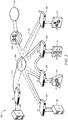
- FIG. 3 is a schematic diagram of a network 300 for implementing a software defined overlay network for creating and enforcing ordered service chains according to a disclosed embodiment.
- the network 300 may be an Ethernet network, an Internet Protocol (IP) network, Multi-Protocol Label Switching (MPLS) network, or any other packet switched network (PSN).
- IP Internet Protocol
- MPLS Multi-Protocol Label Switching
- PSN packet switched network
- the network 300 may comprise a combination of different types of PSNs.
- the network 300 may comprise end points 302, SDNS nodes 304, a network domain 306, an edge node 308, an external domain 310, and service devices 312.
- the end points 302 may be file servers or other devices that provide files or data to clients.
- the SDNS nodes 304 and similarly the edge node 308 may be any nodes, devices, or components configured to receive, transmit, and/or forward packets in the network 300.
- the network domain 306 may comprise an OSI L2 or an OSI layer 3 (L3) for transferring data.
- the network domain 306 may comprise a plurality of nodes, switches, routers, or other devices configured to receive, transmit and/or forward packets.
- the edge node 308 may facilitate communication between the components 302, 304, 306, and 312 and devices (e.g., clients) located in an external domain 310.
- the service devices 312 (which may also be referred to as service platforms) may process the data packets flowing through the network 300 and apply various services.
- Examples of services that may be provided by service devices 312 include a firewall, server load balancing, encryption/decryption, WAN optimization, and a monitoring service.
- the transport mechanism between the components of network 300 may be any transport system capable of transporting data packets between components.
- the transport mechanism may be an L2 network, an L3 network, an Ethernet, and/or a Transmission Control Protocol/Internet Protocol (TCP/IP) based network.
- TCP/IP Transmission Control Protocol/Internet Protocol
- the SDNS nodes 304 may be configured to implement software defined service chains.
- the SDNS nodes 304 may maintain encapsulation tunnels or mechanisms (e.g., VLANs, VXLANs) between each other and may use the encapsulation tunnels to forward encapsulated data packets.
- the SDNS nodes 304 may be configured to form a logical service chain sequence through which network traffic (e.g., data packets) may be forced in order to apply specific network born services in a specific order.
- the SDNS nodes 304 may provide for flexible logical service chains and data paths that allow a simple insertion, removal, or modification of service elements in the logical chain.
- the SDNS nodes 304 may be configured to classify inbound data packet based on the type of data packet, the source, the destination, the ingress point, and/or some other classification system.
- the classification or the tag may correspond to an administrative set of rules for applying an ordered chain of services.
- the classification system may indicate a service chain order for applying services to the data packet.
- the SDNS node 304 closest to the data flow source may classify the inbound data packet.
- the SDNS node 304 may map the classification to a tag that represents that class, type, or group of data packets.
- the tag may provide an SDNS node 304 with an identification of the specific ordered service chain to apply to the data packet, a next hop in the chain of the ordered service chain, and/or identify the rules for forwarding the data packet.
- the SDNS node 304 may encapsulate the data packet (including the tag or other identifier) and route the encapsulated data packet to a specific encapsulation tunnel or mechanism (e.g., an existing VLAN) based on the classification and/or tag.
- the encapsulated data packet may comprise the tag or classifier.
- the classification and/or tag may be associated with a specified ordered service chain.
- the specified ordered service chain may change over time and may be changed by an administrator.
- the rules to determine an ordered service chain for a data packet based on the classification or tag associated with the data packet may be pushed or transmitted to all the SDNS nodes 304 by an administrator. After encapsulation, the encapsulated inbound data packet may be transported across the network 300 via the encapsulated tunnel.
- a SDNS node 304 (e.g., an intermediate node) nearest or connected to a specified next service device 312 may receive and decapsulate the data packet. Based on the tag or other information in the payload of the data packet, the intermediate SDNS node 304 may determine that the data packet should be forwarded to the attached service device 312 for processing. Based on this determination, the intermediate SDNS node 304 may forward the decapsulated native data packet to a service device 312 connected to the SDNS node 304 for processing by the service device 312. The service device 312 may return the processed data packet back to the SDNS node 304 from which the service device 312 received the data packet.
- the SDNS node 304 nearest the service device 312 may receive the data packet, reclassify and remap the data packet, tag the data packet, encapsulate the data packet and router the encapsulated data packet to a specif encapsulation tunnel or mechanism based on the classification and/or tag.
- the reclassification and re-tagging may result in the same or different classification or tag as that done by the first SDNS node 304.
- the encapsulated data packet may be routed to the next SDNS node 304 specified by the service chain order that may be identified by the classification and/or tag.
- the next SDNS node 304 may perform steps similar to the previous SDNS node 304 if another service is to be applied to the data packet.
- the data packet may be received by a SDNS node 304 (e.g., egress node) closest to the destination of the data packet.
- the egress SDNS node 304 may decapsulate the data packet and forward the data packet to the destination (e.g., end point 302 or a client coupled to external domain 310).
- the data packet may be forwarded across the network domain 306 by nodes (e.g., switches, routers, etc.) not participating in the encapsulation/decapsulation mechanism and which may not be aware of the underlying nature of the encapsulated data packet.
- the solid arrows 314 and the dashed arrows 316 indicate examples of data flows through the network 300.
- arrow 314 shows the data path for a first data flow.
- the data flow may originate in end point 302 (labeled A) and be transmitted to SDNS node 304 (labeled N1).
- Node N1 may classify and/or tag the data flow, encapsulate the data flow and transmit the encapsulated data flow to node N4 via the network domain 306.
- the nodes, switches, routers, and devices of network domain 306 may forward the encapsulated packet without being aware of the underlying content and without decapsulating and inspecting the payload.
- Node N4 may decapsulate the data flow and forward the decapsulated data flow to service device S2 for processing.
- the service device S2 may forward the processed data flow back to node N4 which may reclassify, re-tag, and re-encapsulate the data flow and then forward the re-encapsulated data flow through an existing encapsulation tunnel (e.g., a VLAN, a VXLAN) to node N3 through network domain 306.
- an existing encapsulation tunnel e.g., a VLAN, a VXLAN
- node N3 may decapsulate the data flow, forward the decapsulated data flow to service device S1 for processing, receive the processed data flow from service device 312, reclassify, re-tag, and re-encapsulate the data flow, and forward the encapsulated data flow through an existing encapsulation tunnel to node N2 via network domain 306.
- Node N2. may receive the encapsulated data flow, decapsulate the data flow and forward the decapsulated data flow to the end point B. End point B may return a data flow back to end point A, which may follow the same course in reverse order back to end point A and processed in a similar manner on the return path.
- Arrow 316 may represent the path of another data flow entering the network 300 from external domain 310 at router 308.
- the data flow represented by arrow 316 may follow a path as shown in FIG. 3 and may be handled in a similar manner to that of the data flow associated with arrow 314.
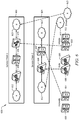
- FIG. 4 is a schematic diagram of a network 400 implementing a software defined overlay network for creating and enforcing ordered service chains according to a disclosed embodiment.
- Network 400 may comprise routers 402, aggregation points 404, L2 switches 406, and service devices 408.
- Routers 404 may connect network 400 with other clients, servers, nodes, devices, networks, and/or domains.
- the routers 402 may be connected to the aggregation points 404.
- the aggregation points 404 may be connected to the L2 switches 406 that may provide a connection to the service devices 408.
- the L2 switches may be similar to SDNS nodes 304 in FIG. 3 .
- the L2 switches 406 may have encapsulated tunnels configured to connect to each other through aggregation points 404.
- the service devices 408 may be similar to service devices 312 in FIG. 3 .
- the service devices do not need to have VLANs configured to couple to the aggregation points for each service chain path. Rather, the service devices are directly connected to the L2 switches 406, and the service order chaining mechanism implemented by the L2 switches is transparent to the service devices 408, the routers 402, and the aggregation points 404.
- the service order chaining mechanism may be transparent to the service devices 408, the routers 402, and the aggregation points 404 since the ordering may be performed by the L2 switches 406 that encapsulate and decapsulate the data packets. The ordering may be encoded in the encapsulated data packets.
- the service devices 408, the routers 402, and the aggregation points 404 may not participate in the encapsulation/decapsulation processes.
- FIG. 5 is a schematic diagram of a network 500 for implementing a software defined overlay network for creating and enforcing ordered service chains according to a disclosed embodiment.
- Network 500 may comprise a domain 502 and a plurality of service devices 504.
- the service devices 504 may be connected directly to edge devices 506 in the domain 502.
- the edge devices 506 may be similar to SDNS nodes 304 in FIG. 3 .
- FIG. 5 shows that, in contrast to network 200 in FIG. 2 , the service devices 504 do not need to be connected to the rest of the network 500 via VLANs or other encapsulated tunnels.
- FIG. 6 is a diagram of a user interface 600 for creating ordered service chains according to a disclosed embodiment.
- the user interface 600 may comprise a plurality of icons representing different services and groups within a network, such as network 300.
- the service icons may include firewall icons 606, 607, SLB icons 608, 609, Wide Area Application Services (WAAS) icons 610, 611, and group A icon 612 and group B icon 613.
- An administrator may select various icons and move a copy of the icon into a service chain area 602, 604.
- the administrator may order the icons 606-613 in the service chain areas 602, 604 to create a rule for an ordered service chain that may be promulgated to SDNS nodes 304 for implementation.
- the user interface 600 shows two service chains.
- Service chain 1 in service chain area 602 shows an ordered service chain comprising group A 612, SLB 608, firewall 606, WAcc 611, and group B 613.
- Service chain 2 in service chain area 604 shows an ordered service chain comprising group A 612, SLB 608, firewall 607, and group B.
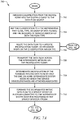
- FIGS. 7A and 7B show a flowchart of a method 700 for implementing a software defined service chain according to a disclosed embodiment.
- the method 700 may begin at block 702 where a SDNS node 304 at an ingress point in the network 300 closest to an inbound data flow so may classify the inbound data flow.
- the SDNS node 304 may map the classification to a tag representing the class, type, or group of the data flow and that representing the sequence of services associated with the flow type..
- the SDNS node 304 may encapsulate the data flow and route the data flow to a specific encapsulation tunnel or mechanism based on the classification and/or tag.
- the encapsulated data flow may be transported across the intermediate network via the encapsulated tunnel.
- an intermediate SDNS node 304 to which the service devices/instances 312 are attached may decapsulate the tunneled payload data flow.
- the intermediate SDNS nodes 304 to which a service device/instance 312 is not attached or that the service for the service device/instance 312 is not used for the particular data flow may refrain from decapsulating the tunneled payload data flow.
- the intermediate SDNS node 304 may forward the decapsulated native data flow to a service device or platform 312, service device 408, service device 504, or one of service devices 606-611 connected to the intermediate SDNS node 304 or L2 switch 406 for processing by the service device/platform 312, service device 408, service device 504, or one of service devices 606-611.
- the service device/platform 312, service device 408, service device 504, or one of service devices 606-611 may return the data flow traffic to the directly connected intermediate SDNS node 304 or L2 switch 406.
- the method 700 may proceed to block 718 where the intermediate SDNS node 304 or L2 switch 406 may reclassify, remap, and re-tag the processed data flow from the service device/platform 312, service device 408, service device 504, or one of service devices 606-611, after which the method 700 may proceed to block 706.
- the method 700 may proceed to block 720 the data flow may be forwarded to the destination (e.g., endpoint 302, domain 310, or one of domains 612, 613), after which, the method 700 may end.
- the disclosed methods, systems, and apparatuses include software defined forwarding tables to allow Top of Rack (ToR) to classify traffic and to define next hop based on classification.
- the disclosed methods, systems, and apparatuses provide flexible service placement: any service can be on any ToR. Additionally, the disclosed methods, systems, and apparatuses scales with number of ToRs (horizontal scaling), uses Software Defined Networking (SDN) defined paths for service chains, and VLANs remain localized.
- SDN Software Defined Networking
- the disclosed methods, systems, and apparatuses may lower configuration complexity, which may lower the probability of error/outage.
- the disclosed methods, systems, and methods also provide that the changes are implemented on ToR reducing the scope of potential impact.
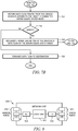
- FIG. 8 illustrates an embodiment of a network unit 800, which may be any device that transports and processes data through the network.
- the network unit 800 may correspond to SDNS nodes 304 described above.
- the network unit 800 may comprise one or more ingress ports or units 810 coupled to a receiver (Rx) 812 for receiving signals and frames/data from other network components.
- the network unit 800 may comprise a logic unit 820 to determine which network components to send data to.
- the logic unit 820 may be implemented using hardware, software, or both.
- the logic unit 820 may be implemented as one or more central processing unit (CPU) chips, or may be part of one or more application specific integrated circuits (ASICs).
- CPU central processing unit
- ASICs application specific integrated circuits
- the network unit 800 may also comprise one or more egress ports or units 830 coupled to a transmitter (Tx) 832 for transmitting signals and frames/data to the other network components.
- the logic unit 820 may also implement or support the software defined networking ordered service chain procedures described above.
- the components of the network unit 800 may be arranged as shown in FIG. 8 .
- R 1 R 1 +k*(R u -R 1 ), wherein k is a variable ranging from 1 percent to 100 percent with a 1 percent increment, i.e., k is 1 percent, 2 percent, 3 percent, 4 percent, 7 percent, ..., 70 percent, 71 percent, 72 percent, ..., 97 percent, 96 percent, 97 percent, 98 percent, 99 percent, or 100 percent.
- any numerical range defined by two R numbers as defined in the above is also specifically disclosed.
Landscapes
- Engineering & Computer Science (AREA)
- Computer Networks & Wireless Communication (AREA)
- Signal Processing (AREA)
- Computing Systems (AREA)
- Theoretical Computer Science (AREA)
- Computer Security & Cryptography (AREA)
- Data Exchanges In Wide-Area Networks (AREA)
Description
- The present invention relates to network communication, and, in particular, to a system for creating software defined ordered service patterns in a communication network.
- Network services are services hosted on a computer network. Network services are usually hosted by servers (or service devices) in the network to provide services or shared resources to client computers. Enterprises may configure network services on a local area network to ensure security, provide e-mail, and provide printing to their employees. Network services may also include a firewall and encryption/decryption services. A specific service may often be assigned or mapped to a specific port number in the network. In some networks, a series of services may need to be provided and the services may need to be provided in a specified order. The services provided and/or the order in which they are provided may change over time. Thus, the network may need to be reconfigured to accommodate the changes.
- ERIK NORDSTROM ET AL: "Serval: An End-Host Stack for Service-Centric Networking", 9th Usenix Symposium on networked Systems Design and Implementation, 25 April 2012, San Jose, CA discloses a network architecture named Serval. The Serval-to-TCP translator receives a Serval format packet with a serviceID. The serviceID is a global identifier uniquely identifies a specific service or a group of same services. A Serval-to-TCP/UDP translator converts a Serval connection into a legacy transport connection. After the conversion, the packet is forwarded by legacy IP routing.
- Salvestrini ET AL: "CHANGE: Enabling Innovation in the Internet Architecture through Flexible Flow-Processing Extensions D4.2 Inter-platform signalling", 30 January 2012, pages 1-68 discloses only an MPLS network. The label in an MPLS packet is used by only one device in the path. Forwarding the decapsulated data packet is not disclosed. Moreover, a service device attached to the SDNS node being determined based on the tag is not disclosed.
- In one embodiment, the disclosure includes a software defined network service (SDNS) node for altering a logical flow of data packets in a network to accommodate predetermined ordered service chains, comprising a receiver configured to receive an encapsulated data packet comprising a tag via a encapsulated tunnel from another SDNS node, wherein the tag identifies an ordered service chain or a next hop in the ordered service chain, a processor coupled to the receiver and configured to decapsulate the encapsulated data packet, and a transmitter coupled to the processor and configured to forward the decapsulated data packet to a service device attached to the SDNS node when the processor determines, based on the tag, that a service on the service device should be applied to the data packet.
- These and other features will be more clearly understood from the following detailed description taken in conjunction with the accompanying drawings and claims.
- For a more complete understanding of this disclosure, reference is now made to the following brief description, taken in connection with the accompanying drawings and detailed description, wherein like reference numerals represent like parts.
-
FIG. 1 is a diagram of a network for providing network services to clients. -
FIG. 2 is another example of a network for providing network services to clients. -
FIG. 3 is a schematic diagram of a network implementing a software defined overlay network for creating and enforcing ordered service chains according to a disclosed embodiment. -
FIG. 4 is a schematic diagram of a network implementing a software defined overlay network for creating and enforcing ordered service chains according to a disclosed embodiment. -
FIG. 5 is a schematic diagram of a network for implementing a software defined overlay network for creating and enforcing ordered service chains according to a disclosed embodiment. -
FIG. 6 is a diagram of a user interface for creating ordered service chains according to a disclosed embodiment. -
FIGS. 7A and7B show a flowchart of a method for implementing a software defined service chain according to a disclosed embodiment. -
FIG. 8 is a schematic diagram illustrating an embodiment of a network unit, which may be any device that transports and processes data through the network. - It should be understood at the outset that although an illustrative implementation of one or more embodiments are provided below, the disclosed systems and/or methods may be implemented using any number of techniques, whether currently known or in existence. The disclosure should in no way be limited to the illustrative implementations, drawings, and techniques illustrated below, including the exemplary designs and implementations illustrated and described herein, but may be modified within the scope of the appended claims.
FIG. 1 is a diagram of anetwork 100 for providing network services to clients.Network 100 may comprise a plurality ofrouters 102, a plurality ofaggregation points 104, a plurality ofservice devices 106, and a plurality of switches 108 (e.g., Open Systems Interconnection (OSI) Layer 2 (L2) switches). Therouters 102 may couple thenetwork 100 to other networks or other devices or clients (not shown) in thenetwork 100. Theaggregation points 104 may be coupled to therouters 102 and configured to enforce service chains (e.g., two or more services that may need to be executed in a specified order) that may be provided to clients coupled to therouters 102. Theswitches 108 may be coupled to theaggregation points 104 as shown and may connect thenetwork 100 to other devices (not shown). Theservice devices 106 may provide various services, such as a firewall, encryption/decryption, wide area network (WAN) optimization, server load balancing (SLB), and monitoring services. The services provided by theservice devices 106 may enforce various security policies for an enterprise to ensure, for example, that files are not accessed without authorization and to ensure the integrity of the files. The services and order of services in a service chain may change with time. For example, the services provided by theservice devices 106 used by an enterprise to ensure security may change over time to address new threats that may appear. Furthermore, the enterprise may have multiple service chains that are implemented in different situations. - The
network 100 may use a spanning tree protocol (STP) (as defined in Institute of Electrical and Electronics Engineers (IEEE) 802.1D) based L2 forwarding path for service path determination. Each chain link (link between services) may require a unique virtual local area network (VLAN), and the VLANs may span the network topology. Each permutation of service chains may require a new L2/STP path and additional VLANs. Changing the service chains innetwork 100 may require a complex reconfiguration of the L2 path and the service devices. Thenetwork 100 may be inflexible in terms of service placement and the scalability may be limited to port density of theaggregation devices 104. Additionally, complexity in deployment and changes is very high, which may increase the probability of an error or an outage. Changes affect theaggregation points 104 which magnify the potential impact of any errors introduced by the changes. Furthermore, the service devices must be made aware of changes to the service chains.FIG. 2 is another example of anetwork 200 for providing network services to clients. Thenetwork 200 may comprise a plurality ofdomains service devices network 200 may require that communication between clients indomain 202, and clients indomain 203 be required to pass through a firewall inservice device 210. Similarly, the security requirements for thenetwork 200 may require that communication between clients indomain 202 and clients indomain 204 pass through a firewall inservice device 212. The security requirements for thenetwork 200 may require that all communications to or from client indomain 203 pass through a firewall inservice device 211. To accomplish these security requirements, L2/STP VLANs domains service devices network 100, changes tonetwork 200 may require a complex reconfiguration of the L2 path and the service devices. Furthermore,network 200 may suffer from many or all of the problems associated withnetwork 100. - Disclosed herein are systems, methods, and apparatuses for software defined service chains. This disclosure outlines a method to employ a software defined overlay network that provides logical path forwarding alteration, via classification, tagging, and encapsulation to enable the direction of traffic through one (or more) network services or service platforms. The disclosed system may combine software defined classification, forwarding, encapsulation rules, and an overlay encapsulation that provides the ability to allow for the creation of a logical sub-network that can be modified arbitrarily with little overall impact to the network or existing data flows. This may effectively create a logical "service chain" where each link in the chain is a service stop allowing the application of one or more network services. In an embodiment, a software defined network service (SDNS) node closest to the source of a data packet may classify the data packet, map the classification to a tag representing that class, type, or group of data, and route the data packet to a specific encapsulation tunnel based on the classification. Intermediate SDNS nodes may decapsulate the data packet and forward the decapsulated data packet to a service device for processing and then receive the processed data packet back from the service device. The intermediate SDNS node may re-encapsulate the processed data packet based on the tag or classification and forward the encapsulated data packet to the next hop in the service chain until all services have been applied to the data packet in the specified order. The data packet may be decapsulated by a last SDNS node in the service chain and forwarded to the end point or client. The service devices and end points need not be aware of the encapsulation mechanism and need not be modified. Other nodes (e.g., switches, routers, etc.) in the network may forward the encapsulated packets without being aware of the encapsulation.
- The combination of software defined classification, forwarding, encapsulation rules and the overlay encapsulation ability may allow for the creation of a logical sub-network that can be modified arbitrarily with little overall impact to the network or existing data flows. This effectively creates logical "service chains" where each link in the chain is a service stop allowing the application of one or more network services.
- The disclosed software programmed classification, forwarding, and encapsulation to create network service based traffic engineering may provide the ability to create arbitrary (e.g. defined by an administrator without creating new VLANs or other tunnels) logical traffic paths to apply arbitrary data path services in a specific order. This in turn may introduce novel methods of load balancing and scaling the services, which is not possible using current or traditional methods of implementation or deployment without creating and configuring additional tunnels, which may be quite complicated and expensive. In some embodiments, the disclosed system provides a mechanism to use the unique identifiers present in the encapsulation mechanism such as Virtual eXtensible Local Area Network (VXLAN), Network Virtualization using Generic Routing Encapsulation (NVGRE), etc. to uniquely identify/encode a service sequence to which the traffic should be redirected based on the classification. The unique identifiers may be certain fields present in various encapsulation mechanisms. For example, the unique identifier may include the VNI in the VXLAN encapsulation mechanism and may include the tenant ID in the NVGRE encapsulation mechanism. The unique identifiers (or tags) may be used to encode the service sequence, class, type, etc. This may not require any new information in the encapsulation headers. Instead, the encapsulation mechanism may reuse existing headers in a unique way to define a service sequence which is understood and interpreted only by certain network elements (e.g., SDNS nodes). The rest of the network may be transparent to the disclosed mechanism since the SDNS nodes may encapsulate the data packets during transport to other SDNS nodes and decapsulate the data packets for transmission to the services and/or destinations. In an embodiment, the disclosed mechanisms and methods may use existing hardware that already supports encapsulation mechanisms.
- The disclosed system and methods provide a mechanism for mapping the uniquely encoded encapsulation header identities (i.e., tags) to the entities that the existing services (e.g., VLANs) can understand and vice versa to maintain the transparency of services to the service sequencing mechanisms. The disclosed systems and methods may ensure that there is no change required in the services and may enable easy plug and play for third party services. The disclosed methods may maintain the mapping in network elements while the services remain transparent to the service sequencing, thereby enabling easier, faster, and transparent deployment. For example, the tag may be a virtual network interface (VNI) when the tunnel encapsulation is a VXLAN. The tag may be a tenant identifier (ID) when the encapsulation mechanism is NVGRE. VNI is part of the VXLAN header and tenant ID is part of the NVGRE header. Other tags may be used for different encapsulation mechanisms. Thus, the mapping maintained in the network elements may be, for example, a VNI to VLAN mapping or a tenant identifier to VLAN mapping. The network elements may maintain a mapping between the identifier present in the network (e.g., a VLAN identifier) to the identifier that the service devices may understand. The mapping may be localized to the device to which the service is attached. The disclosed systems and methods may decouple services from the physical topology. The disclosed systems and methods may reduce operation expenses as compared with current or traditional methods of implementation or deployment of network services. Additionally, the disclosed systems and methods may provide a more flexible use of existing resources and improve the long-term data center lifecycle. The disclosed systems and methods may also enable services virtualization.
-
FIG. 3 is a schematic diagram of anetwork 300 for implementing a software defined overlay network for creating and enforcing ordered service chains according to a disclosed embodiment. Thenetwork 300 may be an Ethernet network, an Internet Protocol (IP) network, Multi-Protocol Label Switching (MPLS) network, or any other packet switched network (PSN). Thenetwork 300 may comprise a combination of different types of PSNs. Thenetwork 300 may compriseend points 302,SDNS nodes 304, anetwork domain 306, anedge node 308, anexternal domain 310, andservice devices 312. The end points 302 may be file servers or other devices that provide files or data to clients. TheSDNS nodes 304 and similarly theedge node 308 may be any nodes, devices, or components configured to receive, transmit, and/or forward packets in thenetwork 300. Thenetwork domain 306 may comprise an OSI L2 or an OSI layer 3 (L3) for transferring data. Thenetwork domain 306 may comprise a plurality of nodes, switches, routers, or other devices configured to receive, transmit and/or forward packets. Theedge node 308 may facilitate communication between thecomponents external domain 310. The service devices 312 (which may also be referred to as service platforms) may process the data packets flowing through thenetwork 300 and apply various services. Examples of services that may be provided byservice devices 312 include a firewall, server load balancing, encryption/decryption, WAN optimization, and a monitoring service. The transport mechanism between the components ofnetwork 300 may be any transport system capable of transporting data packets between components. The transport mechanism may be an L2 network, an L3 network, an Ethernet, and/or a Transmission Control Protocol/Internet Protocol (TCP/IP) based network. The components ofnetwork 300 may be arranged as shown inFIG. 3 . - The
SDNS nodes 304 may be configured to implement software defined service chains. TheSDNS nodes 304 may maintain encapsulation tunnels or mechanisms (e.g., VLANs, VXLANs) between each other and may use the encapsulation tunnels to forward encapsulated data packets. TheSDNS nodes 304 may be configured to form a logical service chain sequence through which network traffic (e.g., data packets) may be forced in order to apply specific network born services in a specific order. TheSDNS nodes 304 may provide for flexible logical service chains and data paths that allow a simple insertion, removal, or modification of service elements in the logical chain. TheSDNS nodes 304 may be configured to classify inbound data packet based on the type of data packet, the source, the destination, the ingress point, and/or some other classification system. The classification or the tag may correspond to an administrative set of rules for applying an ordered chain of services. Thus, the classification system may indicate a service chain order for applying services to the data packet. In an embodiment, theSDNS node 304 closest to the data flow source may classify the inbound data packet. TheSDNS node 304 may map the classification to a tag that represents that class, type, or group of data packets. The tag may provide anSDNS node 304 with an identification of the specific ordered service chain to apply to the data packet, a next hop in the chain of the ordered service chain, and/or identify the rules for forwarding the data packet. TheSDNS node 304 may encapsulate the data packet (including the tag or other identifier) and route the encapsulated data packet to a specific encapsulation tunnel or mechanism (e.g., an existing VLAN) based on the classification and/or tag. The encapsulated data packet may comprise the tag or classifier. The classification and/or tag may be associated with a specified ordered service chain. The specified ordered service chain may change over time and may be changed by an administrator. The rules to determine an ordered service chain for a data packet based on the classification or tag associated with the data packet may be pushed or transmitted to all theSDNS nodes 304 by an administrator. After encapsulation, the encapsulated inbound data packet may be transported across thenetwork 300 via the encapsulated tunnel. - A SDNS node 304 (e.g., an intermediate node) nearest or connected to a specified
next service device 312 may receive and decapsulate the data packet. Based on the tag or other information in the payload of the data packet, theintermediate SDNS node 304 may determine that the data packet should be forwarded to the attachedservice device 312 for processing. Based on this determination, theintermediate SDNS node 304 may forward the decapsulated native data packet to aservice device 312 connected to theSDNS node 304 for processing by theservice device 312. Theservice device 312 may return the processed data packet back to theSDNS node 304 from which theservice device 312 received the data packet. TheSDNS node 304 nearest theservice device 312 may receive the data packet, reclassify and remap the data packet, tag the data packet, encapsulate the data packet and router the encapsulated data packet to a specif encapsulation tunnel or mechanism based on the classification and/or tag. The reclassification and re-tagging may result in the same or different classification or tag as that done by thefirst SDNS node 304. The encapsulated data packet may be routed to thenext SDNS node 304 specified by the service chain order that may be identified by the classification and/or tag. - The
next SDNS node 304 may perform steps similar to theprevious SDNS node 304 if another service is to be applied to the data packet. When all the services have been applied as specified by an administrative set of rules governing ordered service chains, the data packet may be received by a SDNS node 304 (e.g., egress node) closest to the destination of the data packet. Theegress SDNS node 304 may decapsulate the data packet and forward the data packet to the destination (e.g.,end point 302 or a client coupled to external domain 310). - The data packet may be forwarded across the
network domain 306 by nodes (e.g., switches, routers, etc.) not participating in the encapsulation/decapsulation mechanism and which may not be aware of the underlying nature of the encapsulated data packet. Thesolid arrows 314 and the dashedarrows 316 indicate examples of data flows through thenetwork 300. For example,arrow 314 shows the data path for a first data flow. The data flow may originate in end point 302 (labeled A) and be transmitted to SDNS node 304 (labeled N1). Node N1 may classify and/or tag the data flow, encapsulate the data flow and transmit the encapsulated data flow to node N4 via thenetwork domain 306. The nodes, switches, routers, and devices ofnetwork domain 306 may forward the encapsulated packet without being aware of the underlying content and without decapsulating and inspecting the payload. Node N4 may decapsulate the data flow and forward the decapsulated data flow to service device S2 for processing. The service device S2 may forward the processed data flow back to node N4 which may reclassify, re-tag, and re-encapsulate the data flow and then forward the re-encapsulated data flow through an existing encapsulation tunnel (e.g., a VLAN, a VXLAN) to node N3 throughnetwork domain 306. Similarly, node N3 may decapsulate the data flow, forward the decapsulated data flow to service device S1 for processing, receive the processed data flow fromservice device 312, reclassify, re-tag, and re-encapsulate the data flow, and forward the encapsulated data flow through an existing encapsulation tunnel to node N2 vianetwork domain 306. Node N2. may receive the encapsulated data flow, decapsulate the data flow and forward the decapsulated data flow to the end point B. End point B may return a data flow back to end point A, which may follow the same course in reverse order back to end point A and processed in a similar manner on the return path. -
Arrow 316 may represent the path of another data flow entering thenetwork 300 fromexternal domain 310 atrouter 308. The data flow represented byarrow 316 may follow a path as shown inFIG. 3 and may be handled in a similar manner to that of the data flow associated witharrow 314. -
FIG. 4 is a schematic diagram of anetwork 400 implementing a software defined overlay network for creating and enforcing ordered service chains according to a disclosed embodiment.Network 400 may compriserouters 402, aggregation points 404, L2 switches 406, andservice devices 408.Routers 404 may connectnetwork 400 with other clients, servers, nodes, devices, networks, and/or domains. Therouters 402 may be connected to the aggregation points 404. The aggregation points 404 may be connected to the L2 switches 406 that may provide a connection to theservice devices 408. The L2 switches may be similar toSDNS nodes 304 inFIG. 3 . The L2 switches 406 may have encapsulated tunnels configured to connect to each other through aggregation points 404. Theservice devices 408 may be similar toservice devices 312 inFIG. 3 . In contrast to network 100 inFIG. 1 , the service devices do not need to have VLANs configured to couple to the aggregation points for each service chain path. Rather, the service devices are directly connected to the L2 switches 406, and the service order chaining mechanism implemented by the L2 switches is transparent to theservice devices 408, therouters 402, and the aggregation points 404. The service order chaining mechanism may be transparent to theservice devices 408, therouters 402, and the aggregation points 404 since the ordering may be performed by the L2 switches 406 that encapsulate and decapsulate the data packets. The ordering may be encoded in the encapsulated data packets. Theservice devices 408, therouters 402, and the aggregation points 404 may not participate in the encapsulation/decapsulation processes. -
FIG. 5 is a schematic diagram of anetwork 500 for implementing a software defined overlay network for creating and enforcing ordered service chains according to a disclosed embodiment.Network 500 may comprise adomain 502 and a plurality ofservice devices 504. Theservice devices 504 may be connected directly to edgedevices 506 in thedomain 502. Theedge devices 506 may be similar toSDNS nodes 304 inFIG. 3 .FIG. 5 shows that, in contrast tonetwork 200 inFIG. 2 , theservice devices 504 do not need to be connected to the rest of thenetwork 500 via VLANs or other encapsulated tunnels. -
FIG. 6 is a diagram of auser interface 600 for creating ordered service chains according to a disclosed embodiment. Theuser interface 600 may comprise a plurality of icons representing different services and groups within a network, such asnetwork 300. The service icons may includefirewall icons SLB icons icons group A icon 612 andgroup B icon 613. An administrator may select various icons and move a copy of the icon into aservice chain area service chain areas SDNS nodes 304 for implementation. Theuser interface 600 shows two service chains.Service chain 1 inservice chain area 602 shows an ordered service chain comprisinggroup A 612,SLB 608,firewall 606,WAcc 611, andgroup B 613.Service chain 2 inservice chain area 604 shows an ordered service chain comprisinggroup A 612,SLB 608,firewall 607, and group B. -
FIGS. 7A and7B show a flowchart of amethod 700 for implementing a software defined service chain according to a disclosed embodiment. Themethod 700 may begin atblock 702 where aSDNS node 304 at an ingress point in thenetwork 300 closest to an inbound data flow so may classify the inbound data flow. Atblock 704, theSDNS node 304 may map the classification to a tag representing the class, type, or group of the data flow and that representing the sequence of services associated with the flow type.. Atstep 706, theSDNS node 304 may encapsulate the data flow and route the data flow to a specific encapsulation tunnel or mechanism based on the classification and/or tag. Atblock 708, the encapsulated data flow may be transported across the intermediate network via the encapsulated tunnel. - At
block 710, anintermediate SDNS node 304 to which the service devices/instances 312 are attached may decapsulate the tunneled payload data flow. (Theintermediate SDNS nodes 304 to which a service device/instance 312 is not attached or that the service for the service device/instance 312 is not used for the particular data flow may refrain from decapsulating the tunneled payload data flow.) Atblock 712, theintermediate SDNS node 304 may forward the decapsulated native data flow to a service device orplatform 312,service device 408,service device 504, or one of service devices 606-611 connected to theintermediate SDNS node 304 orL2 switch 406 for processing by the service device/platform 312,service device 408,service device 504, or one of service devices 606-611. Atblock 714, the service device/platform 312,service device 408,service device 504, or one of service devices 606-611 may return the data flow traffic to the directly connectedintermediate SDNS node 304 orL2 switch 406. Atblock 716, if there are additional services to be performed on the data flow, themethod 700 may proceed to block 718 where theintermediate SDNS node 304 orL2 switch 406 may reclassify, remap, and re-tag the processed data flow from the service device/platform 312,service device 408,service device 504, or one of service devices 606-611, after which themethod 700 may proceed to block 706. Atblock 716, if there are no additional services to be performed, themethod 700 may proceed to block 720 the data flow may be forwarded to the destination (e.g.,endpoint 302,domain 310, or one ofdomains 612, 613), after which, themethod 700 may end. The disclosed methods, systems, and apparatuses include software defined forwarding tables to allow Top of Rack (ToR) to classify traffic and to define next hop based on classification. The disclosed methods, systems, and apparatuses provide flexible service placement: any service can be on any ToR. Additionally, the disclosed methods, systems, and apparatuses scales with number of ToRs (horizontal scaling), uses Software Defined Networking (SDN) defined paths for service chains, and VLANs remain localized. Furthermore, changes do not require reconfiguration of service devices, thus resulting in a more dynamic network. The disclosed methods, systems, and apparatuses may lower configuration complexity, which may lower the probability of error/outage. The disclosed methods, systems, and methods also provide that the changes are implemented on ToR reducing the scope of potential impact. -
FIG. 8 illustrates an embodiment of anetwork unit 800, which may be any device that transports and processes data through the network. For instance, thenetwork unit 800 may correspond toSDNS nodes 304 described above. Thenetwork unit 800 may comprise one or more ingress ports orunits 810 coupled to a receiver (Rx) 812 for receiving signals and frames/data from other network components. Thenetwork unit 800 may comprise alogic unit 820 to determine which network components to send data to. Thelogic unit 820 may be implemented using hardware, software, or both. Thelogic unit 820 may be implemented as one or more central processing unit (CPU) chips, or may be part of one or more application specific integrated circuits (ASICs). Thenetwork unit 800 may also comprise one or more egress ports orunits 830 coupled to a transmitter (Tx) 832 for transmitting signals and frames/data to the other network components. Thelogic unit 820 may also implement or support the software defined networking ordered service chain procedures described above. The components of thenetwork unit 800 may be arranged as shown inFIG. 8 . - At least one embodiment is disclosed and variations, combinations, and/or modifications of the embodiment(s) and/or features of the embodiment(s) made by a person having ordinary skill in the art are within the scope of the disclosure. Alternative embodiments that result from combining, integrating, and/or omitting features of the embodiment(s) are also within the scope of the disclosure. Where numerical ranges or limitations are expressly stated, such express ranges or limitations should be understood to include iterative ranges or limitations of like magnitude falling within the expressly stated ranges or limitations (e.g., from about 1 to about 10 includes, 2, 3, 4, etc.; greater than 0.10 includes 0.11, 0.12, 0.13, etc.). For example, whenever a numerical range with a lower limit, R1, and an upper limit, Ru, is disclosed, any number falling within the range is specifically disclosed. In particular, the following numbers within the range are specifically disclosed: R=R1+k*(Ru-R1), wherein k is a variable ranging from 1 percent to 100 percent with a 1 percent increment, i.e., k is 1 percent, 2 percent, 3 percent, 4 percent, 7 percent, ..., 70 percent, 71 percent, 72 percent, ..., 97 percent, 96 percent, 97 percent, 98 percent, 99 percent, or 100 percent. Moreover, any numerical range defined by two R numbers as defined in the above is also specifically disclosed. The use of the term about means ±10% of the subsequent number, unless otherwise stated. Use of the term "optionally" with respect to any element of a claim means that the element is required, or alternatively, the element is not required, both alternatives being within the scope of the claim. Use of broader terms such as comprises, includes, and having should be understood to provide support for narrower terms such as consisting of, consisting essentially of, and comprised substantially of. Accordingly, the scope of protection is not limited by the description set out above but is defined by the claims that follow. The discussion of a reference in the disclosure is not an admission that it is prior art, especially any reference that has a publication date after the priority date of this application.
- While several embodiments have been provided in the present disclosure, it should be understood that the disclosed systems and methods might be embodied in many other specific forms without departing from the scope of the present disclosure. The present examples are to be considered as illustrative and not restrictive, and the intention is not to be limited to the details given herein. For example, the various elements or components may be combined or integrated in another system or certain features may be omitted, or not implemented.
- In addition, techniques, systems, subsystems, and methods described and illustrated in the various embodiments as discrete or separate may be combined or integrated with other systems, modules, techniques, or methods without departing from the scope of the present disclosure. Other items shown or discussed as coupled or directly coupled or communicating with each other may be indirectly coupled or communicating through some interface, device, or intermediate component whether electrically, mechanically, or otherwise. Other examples of changes, substitutions, and alterations are ascertainable by one skilled in the art and could be made without departing from the scope disclosed herein.
Claims (2)
- A software defined network service, SDNS, node for altering a logical flow of data packets in a network to accommodate predetermined ordered service chains, comprising:a receiver (812) configured to receive an encapsulated data packet comprising a first tag via a encapsulated tunnel from another SDNS node, wherein the first tag identifies an ordered service chain or a next hop in the ordered service chain;a processor coupled to the receiver and configured to decapsulate the encapsulated data packet; anda transmitter (832) coupled to the processor and configured to forward the decapsulated data packet to a service device attached to the SDNS node when the processor determines, based on the first tag, that a service on the service device should be applied to the data packet;
the receiver is further configured to receive a processed data packet from the service device;
the processor is further configured to:classify the processed data packet;map the classification of the processed data packet to a second tag;encapsulate the processed data packet,wherein the encapsulated processed data packet comprises the second tag,wherein the second tag indicates the ordered service chain or the next hop in the ordered service chain; andcause the transmitter to forward the encapsulated processed data packet to a next SDNS node via a second encapsulated tunnel. - The SDNS node of claim 1, wherein the services or the order of the services in the ordered service chain may be changed without creating a new encapsulated tunnel.
Applications Claiming Priority (3)
| Application Number | Priority Date | Filing Date | Title |
|---|---|---|---|
| US201261683582P | 2012-08-15 | 2012-08-15 | |
| US13/715,524 US8989192B2 (en) | 2012-08-15 | 2012-12-14 | Method and system for creating software defined ordered service patterns in a communications network |
| PCT/US2013/054932 WO2014028612A1 (en) | 2012-08-15 | 2013-08-14 | Method and system for creating software defined ordered service patterns in a communications network |
Publications (2)
| Publication Number | Publication Date |
|---|---|
| EP2875615A1 EP2875615A1 (en) | 2015-05-27 |
| EP2875615B1 true EP2875615B1 (en) | 2018-03-21 |
Family
ID=50099995
Family Applications (1)
| Application Number | Title | Priority Date | Filing Date |
|---|---|---|---|
| EP13753047.3A Active EP2875615B1 (en) | 2012-08-15 | 2013-08-14 | Device for creating software defined ordered service patterns in a communications network |
Country Status (4)
| Country | Link |
|---|---|
| US (2) | US8989192B2 (en) |
| EP (1) | EP2875615B1 (en) |
| CN (1) | CN104521195B (en) |
| WO (1) | WO2014028612A1 (en) |
Families Citing this family (198)
| Publication number | Priority date | Publication date | Assignee | Title |
|---|---|---|---|---|
| US9716672B2 (en) | 2010-05-28 | 2017-07-25 | Brocade Communications Systems, Inc. | Distributed configuration management for virtual cluster switching |
| US8867552B2 (en) | 2010-05-03 | 2014-10-21 | Brocade Communications Systems, Inc. | Virtual cluster switching |
| US9769016B2 (en) | 2010-06-07 | 2017-09-19 | Brocade Communications Systems, Inc. | Advanced link tracking for virtual cluster switching |
| US9270486B2 (en) | 2010-06-07 | 2016-02-23 | Brocade Communications Systems, Inc. | Name services for virtual cluster switching |
| US9806906B2 (en) | 2010-06-08 | 2017-10-31 | Brocade Communications Systems, Inc. | Flooding packets on a per-virtual-network basis |
| US9608833B2 (en) | 2010-06-08 | 2017-03-28 | Brocade Communications Systems, Inc. | Supporting multiple multicast trees in trill networks |
| US9628293B2 (en) | 2010-06-08 | 2017-04-18 | Brocade Communications Systems, Inc. | Network layer multicasting in trill networks |
| US9807031B2 (en) | 2010-07-16 | 2017-10-31 | Brocade Communications Systems, Inc. | System and method for network configuration |
| US8743885B2 (en) | 2011-05-03 | 2014-06-03 | Cisco Technology, Inc. | Mobile service routing in a network environment |
| US9736085B2 (en) | 2011-08-29 | 2017-08-15 | Brocade Communications Systems, Inc. | End-to end lossless Ethernet in Ethernet fabric |
| US9699117B2 (en) | 2011-11-08 | 2017-07-04 | Brocade Communications Systems, Inc. | Integrated fibre channel support in an ethernet fabric switch |
| US9450870B2 (en) | 2011-11-10 | 2016-09-20 | Brocade Communications Systems, Inc. | System and method for flow management in software-defined networks |
| US9742693B2 (en) | 2012-02-27 | 2017-08-22 | Brocade Communications Systems, Inc. | Dynamic service insertion in a fabric switch |
| CN102629160B (en) | 2012-03-16 | 2016-08-03 | 华为终端有限公司 | A kind of input method, input equipment and terminal |
| US9154416B2 (en) | 2012-03-22 | 2015-10-06 | Brocade Communications Systems, Inc. | Overlay tunnel in a fabric switch |
| US10277464B2 (en) | 2012-05-22 | 2019-04-30 | Arris Enterprises Llc | Client auto-configuration in a multi-switch link aggregation |
| US8989192B2 (en) * | 2012-08-15 | 2015-03-24 | Futurewei Technologies, Inc. | Method and system for creating software defined ordered service patterns in a communications network |
| EP2891277B1 (en) * | 2012-09-26 | 2017-08-09 | Huawei Technologies Co., Ltd. | Overlay virtual gateway for overlay networks |
| US9401872B2 (en) | 2012-11-16 | 2016-07-26 | Brocade Communications Systems, Inc. | Virtual link aggregations across multiple fabric switches |
| US10411997B1 (en) | 2012-12-27 | 2019-09-10 | Sitting Man, Llc | Routing methods, systems, and computer program products for using a region scoped node identifier |
| US10374938B1 (en) | 2012-12-27 | 2019-08-06 | Sitting Man, Llc | Routing methods, systems, and computer program products |
| US10411998B1 (en) | 2012-12-27 | 2019-09-10 | Sitting Man, Llc | Node scope-specific outside-scope identifier-equipped routing methods, systems, and computer program products |
| US10404583B1 (en) | 2012-12-27 | 2019-09-03 | Sitting Man, Llc | Routing methods, systems, and computer program products using multiple outside-scope identifiers |
| US10587505B1 (en) | 2012-12-27 | 2020-03-10 | Sitting Man, Llc | Routing methods, systems, and computer program products |
| US10212076B1 (en) | 2012-12-27 | 2019-02-19 | Sitting Man, Llc | Routing methods, systems, and computer program products for mapping a node-scope specific identifier |
| US10904144B2 (en) | 2012-12-27 | 2021-01-26 | Sitting Man, Llc | Methods, systems, and computer program products for associating a name with a network path |
| US10397100B1 (en) | 2012-12-27 | 2019-08-27 | Sitting Man, Llc | Routing methods, systems, and computer program products using a region scoped outside-scope identifier |
| US10404582B1 (en) | 2012-12-27 | 2019-09-03 | Sitting Man, Llc | Routing methods, systems, and computer program products using an outside-scope indentifier |
| US10419334B1 (en) | 2012-12-27 | 2019-09-17 | Sitting Man, Llc | Internet protocol routing methods, systems, and computer program products |
| US10447575B1 (en) | 2012-12-27 | 2019-10-15 | Sitting Man, Llc | Routing methods, systems, and computer program products |
| US10419335B1 (en) | 2012-12-27 | 2019-09-17 | Sitting Man, Llc | Region scope-specific outside-scope indentifier-equipped routing methods, systems, and computer program products |
| US10476787B1 (en) | 2012-12-27 | 2019-11-12 | Sitting Man, Llc | Routing methods, systems, and computer program products |
| US10397101B1 (en) | 2012-12-27 | 2019-08-27 | Sitting Man, Llc | Routing methods, systems, and computer program products for mapping identifiers |
| US9331946B2 (en) * | 2013-01-08 | 2016-05-03 | Hitachi, Ltd. | Method and apparatus to distribute data center network traffic |
| US9548926B2 (en) | 2013-01-11 | 2017-01-17 | Brocade Communications Systems, Inc. | Multicast traffic load balancing over virtual link aggregation |
| US9413691B2 (en) | 2013-01-11 | 2016-08-09 | Brocade Communications Systems, Inc. | MAC address synchronization in a fabric switch |
| US9565099B2 (en) | 2013-03-01 | 2017-02-07 | Brocade Communications Systems, Inc. | Spanning tree in fabric switches |
| WO2014144837A1 (en) * | 2013-03-15 | 2014-09-18 | A10 Networks, Inc. | Processing data packets using a policy based network path |
| US9282164B2 (en) * | 2013-03-15 | 2016-03-08 | Cisco Technology, Inc. | Application hints for network action |
| WO2014145750A1 (en) | 2013-03-15 | 2014-09-18 | Brocade Communications Systems, Inc. | Scalable gateways for a fabric switch |
| US9794379B2 (en) | 2013-04-26 | 2017-10-17 | Cisco Technology, Inc. | High-efficiency service chaining with agentless service nodes |
| US9225638B2 (en) * | 2013-05-09 | 2015-12-29 | Vmware, Inc. | Method and system for service switching using service tags |
| US9246799B2 (en) | 2013-05-10 | 2016-01-26 | Cisco Technology, Inc. | Data plane learning of bi-directional service chains |
| CN104158916A (en) * | 2013-05-13 | 2014-11-19 | 中兴通讯股份有限公司 | Method and device for device accessing to network |
| CN103346974B (en) | 2013-06-03 | 2015-04-08 | 华为技术有限公司 | Controlling method of service process and network device |
| US9178812B2 (en) | 2013-06-05 | 2015-11-03 | Cisco Technology, Inc. | Stacking metadata contexts for service chains |
| US9444675B2 (en) * | 2013-06-07 | 2016-09-13 | Cisco Technology, Inc. | Determining the operations performed along a service path/service chain |
| US9130775B2 (en) * | 2013-07-10 | 2015-09-08 | Cisco Technology, Inc. | Support for virtual extensible local area network segments across multiple data center sites |
| US9450823B2 (en) * | 2013-08-09 | 2016-09-20 | Nec Corporation | Hybrid network management |
| US9699082B2 (en) * | 2013-08-27 | 2017-07-04 | Cisco Technology, Inc. | Inter-domain network tenant identifier |
| CN104519077A (en) * | 2013-09-26 | 2015-04-15 | 中兴通讯股份有限公司 | Multimedia sharing method, registration method, server and proxy server |
| US10594604B1 (en) * | 2013-10-08 | 2020-03-17 | Juniper Networks, Inc. | End to end application identification and analytics of tunnel encapsulated traffic in the underlay |
| US9596126B2 (en) | 2013-10-10 | 2017-03-14 | Nicira, Inc. | Controller side method of generating and updating a controller assignment list |
| US9385950B2 (en) * | 2013-10-14 | 2016-07-05 | Cisco Technology, Inc. | Configurable service proxy local identifier mapping |
| US9525638B2 (en) * | 2013-10-15 | 2016-12-20 | Internap Corporation | Routing system for internet traffic |
| US9912612B2 (en) | 2013-10-28 | 2018-03-06 | Brocade Communications Systems LLC | Extended ethernet fabric switches |
| US9888405B2 (en) | 2013-11-05 | 2018-02-06 | Cisco Technology, Inc. | Networking apparatuses and packet statistic determination methods employing atomic counters |
| US9397946B1 (en) | 2013-11-05 | 2016-07-19 | Cisco Technology, Inc. | Forwarding to clusters of service nodes |
| US9686180B2 (en) | 2013-11-05 | 2017-06-20 | Cisco Technology, Inc. | Managing routing information for tunnel endpoints in overlay networks |
| US9502111B2 (en) | 2013-11-05 | 2016-11-22 | Cisco Technology, Inc. | Weighted equal cost multipath routing |
| US10778584B2 (en) | 2013-11-05 | 2020-09-15 | Cisco Technology, Inc. | System and method for multi-path load balancing in network fabrics |
| US9374294B1 (en) | 2013-11-05 | 2016-06-21 | Cisco Technology, Inc. | On-demand learning in overlay networks |
| US9655232B2 (en) | 2013-11-05 | 2017-05-16 | Cisco Technology, Inc. | Spanning tree protocol (STP) optimization techniques |
| WO2015069576A1 (en) | 2013-11-05 | 2015-05-14 | Cisco Technology, Inc. | Network fabric overlay |
| US10951522B2 (en) | 2013-11-05 | 2021-03-16 | Cisco Technology, Inc. | IP-based forwarding of bridged and routed IP packets and unicast ARP |
| US9825857B2 (en) | 2013-11-05 | 2017-11-21 | Cisco Technology, Inc. | Method for increasing Layer-3 longest prefix match scale |
| US9769078B2 (en) | 2013-11-05 | 2017-09-19 | Cisco Technology, Inc. | Dynamic flowlet prioritization |
| US9674086B2 (en) | 2013-11-05 | 2017-06-06 | Cisco Technology, Inc. | Work conserving schedular based on ranking |
| US9300580B2 (en) * | 2013-12-19 | 2016-03-29 | International Business Machines Corporation | Virtual machine network controller |
| US9548873B2 (en) | 2014-02-10 | 2017-01-17 | Brocade Communications Systems, Inc. | Virtual extensible LAN tunnel keepalives |
| US9344337B2 (en) * | 2014-03-13 | 2016-05-17 | Cisco Technology, Inc. | Service node originated service chains in a network environment |
| US10581758B2 (en) | 2014-03-19 | 2020-03-03 | Avago Technologies International Sales Pte. Limited | Distributed hot standby links for vLAG |
| US10476698B2 (en) | 2014-03-20 | 2019-11-12 | Avago Technologies International Sales Pte. Limited | Redundent virtual link aggregation group |
| EP3127286B1 (en) * | 2014-03-31 | 2020-08-19 | Telefonaktiebolaget LM Ericsson (publ) | Handling of traffic flows in a communications system |
| CN104980348A (en) * | 2014-04-04 | 2015-10-14 | 中兴通讯股份有限公司 | Business chain routing method, business chain routing system and device in system |
| US10148459B2 (en) | 2014-04-29 | 2018-12-04 | Hewlett Packard Enterprise Development Lp | Network service insertion |
| US10063473B2 (en) | 2014-04-30 | 2018-08-28 | Brocade Communications Systems LLC | Method and system for facilitating switch virtualization in a network of interconnected switches |
| US9800471B2 (en) | 2014-05-13 | 2017-10-24 | Brocade Communications Systems, Inc. | Network extension groups of global VLANs in a fabric switch |
| US20150333930A1 (en) * | 2014-05-15 | 2015-11-19 | Akamai Technologies, Inc. | Dynamic service function chaining |
| US9479443B2 (en) | 2014-05-16 | 2016-10-25 | Cisco Technology, Inc. | System and method for transporting information to services in a network environment |
| US9379931B2 (en) | 2014-05-16 | 2016-06-28 | Cisco Technology, Inc. | System and method for transporting information to services in a network environment |
| CN105227498B (en) | 2014-06-27 | 2018-03-02 | 国际商业机器公司 | Stacking network interchanger and its method used |
| US9634936B2 (en) * | 2014-06-30 | 2017-04-25 | Juniper Networks, Inc. | Service chaining across multiple networks |
| US9832168B2 (en) * | 2014-07-01 | 2017-11-28 | Cable Television Laboratories, Inc. | Service discovery within multi-link networks |
| US10616108B2 (en) | 2014-07-29 | 2020-04-07 | Avago Technologies International Sales Pte. Limited | Scalable MAC address virtualization |
| US9807007B2 (en) | 2014-08-11 | 2017-10-31 | Brocade Communications Systems, Inc. | Progressive MAC address learning |
| CN109861897B (en) * | 2014-08-18 | 2023-09-01 | 华为技术有限公司 | A method, device and system for obtaining correspondence |
| US20180198717A1 (en) * | 2014-08-21 | 2018-07-12 | Zte Corporation (China) | A smart flow classification method/system for network and service function chaining |
| CN105471738B (en) * | 2014-09-09 | 2019-04-23 | 中国电信股份有限公司 | A kind of transmission method and system of service traffics |
| WO2016041606A1 (en) | 2014-09-19 | 2016-03-24 | Nokia Solutions And Networks Oy | Chaining of network service functions in a communication network |
| US10055240B2 (en) | 2014-09-23 | 2018-08-21 | At&T Intellectual Property I, L.P. | Service creation and management |
| WO2016045705A1 (en) * | 2014-09-23 | 2016-03-31 | Nokia Solutions And Networks Oy | Control of communication using service function chaining |
| US10257095B2 (en) | 2014-09-30 | 2019-04-09 | Nicira, Inc. | Dynamically adjusting load balancing |
| US10225137B2 (en) | 2014-09-30 | 2019-03-05 | Nicira, Inc. | Service node selection by an inline service switch |
| US9531590B2 (en) | 2014-09-30 | 2016-12-27 | Nicira, Inc. | Load balancing across a group of load balancers |
| US9798810B2 (en) | 2014-09-30 | 2017-10-24 | At&T Intellectual Property I, L.P. | Methods and apparatus to track changes to a network topology |
| US9699029B2 (en) | 2014-10-10 | 2017-07-04 | Brocade Communications Systems, Inc. | Distributed configuration management in a switch group |
| US20170230252A1 (en) * | 2014-10-24 | 2017-08-10 | ZTE CORPORATION (CHINA) ZTE Plaza | Method and system for deep stats inspection (dsi) based smart analytics for network/service function chaining |
| US9548919B2 (en) * | 2014-10-24 | 2017-01-17 | Cisco Technology, Inc. | Transparent network service header path proxies |
| CN105656744B (en) * | 2014-11-10 | 2019-08-27 | 华为数字技术(苏州)有限公司 | Identification methods, devices, and service chains for service chain paths |
| US10417025B2 (en) | 2014-11-18 | 2019-09-17 | Cisco Technology, Inc. | System and method to chain distributed applications in a network environment |
| US9742807B2 (en) | 2014-11-19 | 2017-08-22 | At&T Intellectual Property I, L.P. | Security enhancements for a software-defined network with network functions virtualization |
| USRE48131E1 (en) | 2014-12-11 | 2020-07-28 | Cisco Technology, Inc. | Metadata augmentation in a service function chain |
| US9660909B2 (en) | 2014-12-11 | 2017-05-23 | Cisco Technology, Inc. | Network service header metadata for load balancing |
| US20160173392A1 (en) * | 2014-12-15 | 2016-06-16 | Tieto Oyj | Service Chain Management |
| CA2963580C (en) * | 2014-12-17 | 2020-04-21 | Huawei Technologies Co., Ltd. | Data forwarding method, device, and system in software-defined networking |
| US9628407B2 (en) | 2014-12-31 | 2017-04-18 | Brocade Communications Systems, Inc. | Multiple software versions in a switch group |
| US9626255B2 (en) | 2014-12-31 | 2017-04-18 | Brocade Communications Systems, Inc. | Online restoration of a switch snapshot |
| US9942097B2 (en) | 2015-01-05 | 2018-04-10 | Brocade Communications Systems LLC | Power management in a network of interconnected switches |
| US10003552B2 (en) | 2015-01-05 | 2018-06-19 | Brocade Communications Systems, Llc. | Distributed bidirectional forwarding detection protocol (D-BFD) for cluster of interconnected switches |
| GB2525701B (en) | 2015-01-08 | 2016-11-30 | Openwave Mobility Inc | A software defined network and a communication network comprising the same |
| US9794193B2 (en) | 2015-01-30 | 2017-10-17 | Gigamon Inc. | Software defined visibility fabric |
| US9749225B2 (en) | 2015-04-17 | 2017-08-29 | Huawei Technologies Co., Ltd. | Software defined network (SDN) control signaling for traffic engineering to enable multi-type transport in a data plane |
| US10038592B2 (en) | 2015-03-17 | 2018-07-31 | Brocade Communications Systems LLC | Identifier assignment to a new switch in a switch group |
| US9807005B2 (en) | 2015-03-17 | 2017-10-31 | Brocade Communications Systems, Inc. | Multi-fabric manager |
| US10594743B2 (en) | 2015-04-03 | 2020-03-17 | Nicira, Inc. | Method, apparatus, and system for implementing a content switch |
| US10579406B2 (en) | 2015-04-08 | 2020-03-03 | Avago Technologies International Sales Pte. Limited | Dynamic orchestration of overlay tunnels |
| US9954799B2 (en) | 2015-05-14 | 2018-04-24 | International Business Machines Corporation | Adaptive service chain management |
| US9762402B2 (en) | 2015-05-20 | 2017-09-12 | Cisco Technology, Inc. | System and method to facilitate the assignment of service functions for service chains in a network environment |
| EP3300317B1 (en) | 2015-06-10 | 2020-08-26 | Huawei Technologies Co., Ltd. | Method, device and system for realizing service link |
| US9749229B2 (en) * | 2015-07-01 | 2017-08-29 | Cisco Technology, Inc. | Forwarding packets with encapsulated service chain headers |
| US20170019303A1 (en) * | 2015-07-14 | 2017-01-19 | Microsoft Technology Licensing, Llc | Service Chains for Network Services |
| US10439929B2 (en) | 2015-07-31 | 2019-10-08 | Avago Technologies International Sales Pte. Limited | Graceful recovery of a multicast-enabled switch |
| CN107210996B (en) * | 2015-09-02 | 2020-02-21 | 华为技术有限公司 | A business chain management method and device |
| US10171303B2 (en) | 2015-09-16 | 2019-01-01 | Avago Technologies International Sales Pte. Limited | IP-based interconnection of switches with a logical chassis |
| US10728096B2 (en) * | 2015-10-02 | 2020-07-28 | Arista Networks, Inc. | Dynamic service device integration |
| CN105376170B (en) * | 2015-11-16 | 2018-08-03 | 中国人民解放军信息工程大学 | A kind of virtualization network function combined method that load balancing is preferential |
| US9912614B2 (en) | 2015-12-07 | 2018-03-06 | Brocade Communications Systems LLC | Interconnection of switches based on hierarchical overlay tunneling |
| US11044203B2 (en) | 2016-01-19 | 2021-06-22 | Cisco Technology, Inc. | System and method for hosting mobile packet core and value-added services using a software defined network and service chains |
| US10397108B2 (en) * | 2016-01-25 | 2019-08-27 | Futurewei Technologies, Inc. | Service function chaining across multiple subnetworks |
| US10187306B2 (en) | 2016-03-24 | 2019-01-22 | Cisco Technology, Inc. | System and method for improved service chaining |
| US11029749B2 (en) * | 2016-04-01 | 2021-06-08 | Platina Systems Corp. | Modular chassis with fabric integrated into the line card |
| US10931793B2 (en) | 2016-04-26 | 2021-02-23 | Cisco Technology, Inc. | System and method for automated rendering of service chaining |
| CN107317752B (en) * | 2016-04-27 | 2020-12-01 | 华为技术有限公司 | Method and device for forwarding data message |
| US10205706B2 (en) * | 2016-05-11 | 2019-02-12 | Argela Yazilim ve Bilisim Teknolojileri San. ve Tic. A.S. | System and method for programmable network based encryption in software defined networks |
| WO2017209863A1 (en) * | 2016-05-31 | 2017-12-07 | Brocade Communications Systems, Inc. | Selective rule management based on traffic visibility in a tunnel |
| US10038627B2 (en) | 2016-05-31 | 2018-07-31 | Brocade Communications Systems LLC | Selective rule management based on traffic visibility in a tunnel |
| CN107493235A (en) * | 2016-06-13 | 2017-12-19 | 中兴通讯股份有限公司 | A kind of method and apparatus of fast-forwarding message |
| WO2017223104A1 (en) * | 2016-06-21 | 2017-12-28 | Imperva, Inc. | Infrastructure distributed denial of service protection |
| US10419550B2 (en) | 2016-07-06 | 2019-09-17 | Cisco Technology, Inc. | Automatic service function validation in a virtual network environment |
| US10218616B2 (en) | 2016-07-21 | 2019-02-26 | Cisco Technology, Inc. | Link selection for communication with a service function cluster |
| US10320664B2 (en) | 2016-07-21 | 2019-06-11 | Cisco Technology, Inc. | Cloud overlay for operations administration and management |
| US10225270B2 (en) | 2016-08-02 | 2019-03-05 | Cisco Technology, Inc. | Steering of cloned traffic in a service function chain |
| US10218593B2 (en) | 2016-08-23 | 2019-02-26 | Cisco Technology, Inc. | Identifying sources of packet drops in a service function chain environment |
| US10361969B2 (en) | 2016-08-30 | 2019-07-23 | Cisco Technology, Inc. | System and method for managing chained services in a network environment |
| US20180069749A1 (en) * | 2016-09-07 | 2018-03-08 | Netscout Systems, Inc | Systems and methods for performing computer network service chain analytics |
| EP3435606B1 (en) * | 2016-09-30 | 2021-02-17 | Huawei Technologies Co., Ltd. | Message processing method, computing device, and message processing apparatus |
| US10361915B2 (en) * | 2016-09-30 | 2019-07-23 | International Business Machines Corporation | System, method and computer program product for network function optimization based on locality and function type |
| US10237090B2 (en) * | 2016-10-28 | 2019-03-19 | Avago Technologies International Sales Pte. Limited | Rule-based network identifier mapping |
| CN108075991B (en) * | 2016-11-18 | 2020-09-08 | 新华三技术有限公司 | Message forwarding method and device |
| US11080274B2 (en) | 2017-01-17 | 2021-08-03 | Futurewei Technologies, Inc. | Best-efforts database functions |
| US10805241B2 (en) * | 2017-01-17 | 2020-10-13 | Futurewei Technologies, Inc. | Database functions-defined network switch and database system |
| US10225187B2 (en) | 2017-03-22 | 2019-03-05 | Cisco Technology, Inc. | System and method for providing a bit indexed service chain |
| US10230632B2 (en) * | 2017-04-05 | 2019-03-12 | At&T Intellectual Property I, L.P. | Systems and methods for tunnel free connectionless packet routing to a service edge |
| US10333855B2 (en) | 2017-04-19 | 2019-06-25 | Cisco Technology, Inc. | Latency reduction in service function paths |
| US10554689B2 (en) | 2017-04-28 | 2020-02-04 | Cisco Technology, Inc. | Secure communication session resumption in a service function chain |
| CN107094111B (en) * | 2017-05-17 | 2020-08-18 | 天津大学 | Label Delivery Method in Software Defined Network Controller Deployment |
| US10735275B2 (en) | 2017-06-16 | 2020-08-04 | Cisco Technology, Inc. | Releasing and retaining resources for use in a NFV environment |
| US10798187B2 (en) | 2017-06-19 | 2020-10-06 | Cisco Technology, Inc. | Secure service chaining |
| US10397271B2 (en) | 2017-07-11 | 2019-08-27 | Cisco Technology, Inc. | Distributed denial of service mitigation for web conferencing |
| US10673698B2 (en) | 2017-07-21 | 2020-06-02 | Cisco Technology, Inc. | Service function chain optimization using live testing |
| CN108418755B (en) * | 2017-07-25 | 2019-10-11 | 新华三技术有限公司 | Data stream transmission method and device |
| US11063856B2 (en) | 2017-08-24 | 2021-07-13 | Cisco Technology, Inc. | Virtual network function monitoring in a network function virtualization deployment |
| US10791065B2 (en) | 2017-09-19 | 2020-09-29 | Cisco Technology, Inc. | Systems and methods for providing container attributes as part of OAM techniques |
| US11018981B2 (en) | 2017-10-13 | 2021-05-25 | Cisco Technology, Inc. | System and method for replication container performance and policy validation using real time network traffic |
| US10541893B2 (en) | 2017-10-25 | 2020-01-21 | Cisco Technology, Inc. | System and method for obtaining micro-service telemetry data |
| US10797966B2 (en) | 2017-10-29 | 2020-10-06 | Nicira, Inc. | Service operation chaining |
| US11012420B2 (en) | 2017-11-15 | 2021-05-18 | Nicira, Inc. | Third-party service chaining using packet encapsulation in a flow-based forwarding element |
| US10659252B2 (en) | 2018-01-26 | 2020-05-19 | Nicira, Inc | Specifying and utilizing paths through a network |
| US10797910B2 (en) | 2018-01-26 | 2020-10-06 | Nicira, Inc. | Specifying and utilizing paths through a network |
| CN111164939B (en) * | 2018-01-26 | 2022-08-23 | Nicira股份有限公司 | Specifying and utilizing paths through a network |
| WO2019153127A1 (en) * | 2018-02-06 | 2019-08-15 | Nokia Shanghai Bell Co., Ltd. | Method, apparatus, and computer readable medium for providing security service for data center |
| US10805192B2 (en) | 2018-03-27 | 2020-10-13 | Nicira, Inc. | Detecting failure of layer 2 service using broadcast messages |
| US10728174B2 (en) | 2018-03-27 | 2020-07-28 | Nicira, Inc. | Incorporating layer 2 service between two interfaces of gateway device |
| US10666612B2 (en) | 2018-06-06 | 2020-05-26 | Cisco Technology, Inc. | Service chains for inter-cloud traffic |
| US10956832B2 (en) | 2018-06-22 | 2021-03-23 | Platina Systems Corporation | Training a data center hardware instance network |
| US10999220B2 (en) | 2018-07-05 | 2021-05-04 | Vmware, Inc. | Context aware middlebox services at datacenter edge |
| US11184327B2 (en) * | 2018-07-05 | 2021-11-23 | Vmware, Inc. | Context aware middlebox services at datacenter edges |
| US10979542B2 (en) * | 2018-08-28 | 2021-04-13 | Vmware, Inc. | Flow cache support for crypto operations and offload |
| US10944673B2 (en) | 2018-09-02 | 2021-03-09 | Vmware, Inc. | Redirection of data messages at logical network gateway |
| US11595250B2 (en) | 2018-09-02 | 2023-02-28 | Vmware, Inc. | Service insertion at logical network gateway |
| US11102114B2 (en) * | 2018-12-28 | 2021-08-24 | Alibaba Group Holding Limited | Method, apparatus, and computer-readable storage medium for network optimization for accessing cloud service from on-premises network |
| US10892989B2 (en) | 2019-01-18 | 2021-01-12 | Vmware, Inc. | Tunnel-based service insertion in public cloud environments |
| US11627080B2 (en) | 2019-01-18 | 2023-04-11 | Vmware, Inc. | Service insertion in public cloud environments |
| US11036538B2 (en) | 2019-02-22 | 2021-06-15 | Vmware, Inc. | Providing services with service VM mobility |
| US11444877B2 (en) * | 2019-03-18 | 2022-09-13 | At&T Intellectual Property I, L.P. | Packet flow identification with reduced decode operations |
| US11032162B2 (en) * | 2019-07-18 | 2021-06-08 | Vmware, Inc. | Mothod, non-transitory computer-readable storage medium, and computer system for endpoint to perform east-west service insertion in public cloud environments |
| US11140218B2 (en) | 2019-10-30 | 2021-10-05 | Vmware, Inc. | Distributed service chain across multiple clouds |
| US11283717B2 (en) | 2019-10-30 | 2022-03-22 | Vmware, Inc. | Distributed fault tolerant service chain |
| US11641305B2 (en) | 2019-12-16 | 2023-05-02 | Vmware, Inc. | Network diagnosis in software-defined networking (SDN) environments |
| US11223494B2 (en) | 2020-01-13 | 2022-01-11 | Vmware, Inc. | Service insertion for multicast traffic at boundary |
| US11153406B2 (en) | 2020-01-20 | 2021-10-19 | Vmware, Inc. | Method of network performance visualization of service function chains |
| US11659061B2 (en) | 2020-01-20 | 2023-05-23 | Vmware, Inc. | Method of adjusting service function chains to improve network performance |
| US11528219B2 (en) | 2020-04-06 | 2022-12-13 | Vmware, Inc. | Using applied-to field to identify connection-tracking records for different interfaces |
| CN111953669B (en) * | 2020-07-30 | 2022-10-25 | 江苏大学 | Tor traffic traceability and application type identification method and system suitable for SDN |
| US11611625B2 (en) | 2020-12-15 | 2023-03-21 | Vmware, Inc. | Providing stateful services in a scalable manner for machines executing on host computers |
| US11734043B2 (en) | 2020-12-15 | 2023-08-22 | Vmware, Inc. | Providing stateful services in a scalable manner for machines executing on host computers |
| CN119814280B (en) * | 2025-03-13 | 2025-05-23 | 中国电子科技集团公司第三十研究所 | Safety service chain construction method based on data tag |
Citations (1)
| Publication number | Priority date | Publication date | Assignee | Title |
|---|---|---|---|---|
| US20110161521A1 (en) * | 2009-12-30 | 2011-06-30 | Verizon Patent And Licensing, Inc. | Management of inter-provider peer-to-peer based feature network |
Family Cites Families (7)
| Publication number | Priority date | Publication date | Assignee | Title |
|---|---|---|---|---|
| US7869450B2 (en) * | 2004-04-05 | 2011-01-11 | Verizon Business Global Llc | Method and apparatus for processing labeled flows in a communication access network |
| US9253274B2 (en) * | 2007-01-19 | 2016-02-02 | Cisco Technology, Inc. | Service insertion architecture |
| US7895425B2 (en) * | 2007-08-03 | 2011-02-22 | Cisco Technology, Inc. | Operation, administration and maintenance (OAM) in a service insertion architecture (SIA) |
| US8526435B2 (en) * | 2010-03-19 | 2013-09-03 | Telefonaktiebolaget L M Ericsson (Publ) | Packet node for applying service path routing at the MAC layer |
| US8830834B2 (en) * | 2011-12-21 | 2014-09-09 | Cisco Technology, Inc. | Overlay-based packet steering |
| US9668161B2 (en) * | 2012-07-09 | 2017-05-30 | Cisco Technology, Inc. | System and method associated with a service flow router |
| US8989192B2 (en) * | 2012-08-15 | 2015-03-24 | Futurewei Technologies, Inc. | Method and system for creating software defined ordered service patterns in a communications network |
-
2012
- 2012-12-14 US US13/715,524 patent/US8989192B2/en active Active
-
2013
- 2013-08-14 EP EP13753047.3A patent/EP2875615B1/en active Active
- 2013-08-14 WO PCT/US2013/054932 patent/WO2014028612A1/en not_active Ceased
- 2013-08-14 CN CN201380040895.5A patent/CN104521195B/en active Active
-
2015
- 2015-02-10 US US14/618,888 patent/US9705702B2/en active Active
Patent Citations (1)
| Publication number | Priority date | Publication date | Assignee | Title |
|---|---|---|---|---|
| US20110161521A1 (en) * | 2009-12-30 | 2011-06-30 | Verizon Patent And Licensing, Inc. | Management of inter-provider peer-to-peer based feature network |
Also Published As
| Publication number | Publication date |
|---|---|
| US8989192B2 (en) | 2015-03-24 |
| CN104521195B (en) | 2018-03-09 |
| EP2875615A1 (en) | 2015-05-27 |
| WO2014028612A1 (en) | 2014-02-20 |
| US20140050223A1 (en) | 2014-02-20 |
| US20150156035A1 (en) | 2015-06-04 |
| CN104521195A (en) | 2015-04-15 |
| US9705702B2 (en) | 2017-07-11 |
Similar Documents
| Publication | Publication Date | Title |
|---|---|---|
| EP2875615B1 (en) | Device for creating software defined ordered service patterns in a communications network | |
| US12255812B1 (en) | Service chaining among devices of interconnected topology | |
| EP3058687B1 (en) | Configurable service proxy mapping | |
| US11956141B2 (en) | Service chaining with physical network functions and virtualized network functions | |
| US7738457B2 (en) | Method and system for virtual routing using containers | |
| US8396954B2 (en) | Routing and service performance management in an application acceleration environment | |
| EP3619895B1 (en) | Efficient troubleshooting in openflow switches | |
| US20150043348A1 (en) | Traffic Flow Redirection between Border Routers using Routing Encapsulation | |
| EP3188422B1 (en) | Traffic black holing avoidance and fast convergence for active-active pbb-evpn redundancy | |
| US20190319871A1 (en) | Multi-VRF Universal Device Internet Protocol Address for Fabric Edge Devices | |
| US11792119B2 (en) | Multi-protocol service chaining among devices of interconnected topology | |
| CN102804693A (en) | Method and apparatus for implementing L2 VPNs on an ip network | |
| US20140219282A1 (en) | Method and Apparatus for Simulating IP Multinetting | |
| US20120224579A1 (en) | Multiprotocol Label Switching (MPLS) Virtual Private Network (VPN) Over Routed Ethernet Backbone | |
| WO2013119777A1 (en) | Virtual local area network identifier substitution as time to live method | |
| US20030210696A1 (en) | System and method for routing across segments of a network switch | |
| CN106936704B (en) | Multipath switching using hop-by-hop VLAN classification | |
| EP3917095A1 (en) | Multi-protocol service chaining among devices of interconnected topology | |
| US9602352B2 (en) | Network element of a software-defined network | |
| Geng et al. | Deterministic networking (DetNet) YANG model | |
| CN119011337A (en) | Message forwarding method, device and system | |
| US12363030B2 (en) | Multi-protocol service chaining among devices of interconnected topology | |
| US20250062991A1 (en) | Egress filtering for e-tree over evpn | |
| Jain | LAN Extension and Network Virtualization in Cloud Data Centers |
Legal Events
| Date | Code | Title | Description |
|---|---|---|---|
| PUAI | Public reference made under article 153(3) epc to a published international application that has entered the european phase |
Free format text: ORIGINAL CODE: 0009012 |
|
| 17P | Request for examination filed |
Effective date: 20150217 |
|
| AK | Designated contracting states |
Kind code of ref document: A1 Designated state(s): AL AT BE BG CH CY CZ DE DK EE ES FI FR GB GR HR HU IE IS IT LI LT LU LV MC MK MT NL NO PL PT RO RS SE SI SK SM TR |
|
| AX | Request for extension of the european patent |
Extension state: BA ME |
|
| 17Q | First examination report despatched |
Effective date: 20150806 |
|
| DAX | Request for extension of the european patent (deleted) | ||
| REG | Reference to a national code |
Ref country code: DE Ref legal event code: R079 Ref document number: 602013034716 Country of ref document: DE Free format text: PREVIOUS MAIN CLASS: H04L0012723000 Ipc: H04L0012701000 |
|
| GRAP | Despatch of communication of intention to grant a patent |
Free format text: ORIGINAL CODE: EPIDOSNIGR1 |
|
| STAA | Information on the status of an ep patent application or granted ep patent |
Free format text: STATUS: GRANT OF PATENT IS INTENDED |
|
| RIC1 | Information provided on ipc code assigned before grant |
Ipc: H04L 12/723 20130101ALI20170928BHEP Ipc: H04L 12/701 20130101AFI20170928BHEP Ipc: H04L 12/46 20060101ALI20170928BHEP Ipc: H04L 12/851 20130101ALI20170928BHEP Ipc: H04L 12/741 20130101ALI20170928BHEP |
|
| INTG | Intention to grant announced |
Effective date: 20171013 |
|
| GRAS | Grant fee paid |
Free format text: ORIGINAL CODE: EPIDOSNIGR3 |
|
| GRAA | (expected) grant |
Free format text: ORIGINAL CODE: 0009210 |
|
| STAA | Information on the status of an ep patent application or granted ep patent |
Free format text: STATUS: THE PATENT HAS BEEN GRANTED |
|
| AK | Designated contracting states |
Kind code of ref document: B1 Designated state(s): AL AT BE BG CH CY CZ DE DK EE ES FI FR GB GR HR HU IE IS IT LI LT LU LV MC MK MT NL NO PL PT RO RS SE SI SK SM TR |
|
| REG | Reference to a national code |
Ref country code: GB Ref legal event code: FG4D |
|
| REG | Reference to a national code |
Ref country code: CH Ref legal event code: EP |
|
| REG | Reference to a national code |
Ref country code: AT Ref legal event code: REF Ref document number: 982243 Country of ref document: AT Kind code of ref document: T Effective date: 20180415 |
|
| REG | Reference to a national code |
Ref country code: IE Ref legal event code: FG4D |
|
| REG | Reference to a national code |
Ref country code: DE Ref legal event code: R096 Ref document number: 602013034716 Country of ref document: DE |
|
| REG | Reference to a national code |
Ref country code: FR Ref legal event code: PLFP Year of fee payment: 6 |
|
| REG | Reference to a national code |
Ref country code: NL Ref legal event code: MP Effective date: 20180321 |
|
| PG25 | Lapsed in a contracting state [announced via postgrant information from national office to epo] |
Ref country code: FI Free format text: LAPSE BECAUSE OF FAILURE TO SUBMIT A TRANSLATION OF THE DESCRIPTION OR TO PAY THE FEE WITHIN THE PRESCRIBED TIME-LIMIT Effective date: 20180321 Ref country code: NO Free format text: LAPSE BECAUSE OF FAILURE TO SUBMIT A TRANSLATION OF THE DESCRIPTION OR TO PAY THE FEE WITHIN THE PRESCRIBED TIME-LIMIT Effective date: 20180621 Ref country code: CY Free format text: LAPSE BECAUSE OF FAILURE TO SUBMIT A TRANSLATION OF THE DESCRIPTION OR TO PAY THE FEE WITHIN THE PRESCRIBED TIME-LIMIT Effective date: 20180321 Ref country code: HR Free format text: LAPSE BECAUSE OF FAILURE TO SUBMIT A TRANSLATION OF THE DESCRIPTION OR TO PAY THE FEE WITHIN THE PRESCRIBED TIME-LIMIT Effective date: 20180321 Ref country code: LT Free format text: LAPSE BECAUSE OF FAILURE TO SUBMIT A TRANSLATION OF THE DESCRIPTION OR TO PAY THE FEE WITHIN THE PRESCRIBED TIME-LIMIT Effective date: 20180321 |
|
| REG | Reference to a national code |
Ref country code: LT Ref legal event code: MG4D |
|
| REG | Reference to a national code |
Ref country code: AT Ref legal event code: MK05 Ref document number: 982243 Country of ref document: AT Kind code of ref document: T Effective date: 20180321 |
|
| PG25 | Lapsed in a contracting state [announced via postgrant information from national office to epo] |
Ref country code: GR Free format text: LAPSE BECAUSE OF FAILURE TO SUBMIT A TRANSLATION OF THE DESCRIPTION OR TO PAY THE FEE WITHIN THE PRESCRIBED TIME-LIMIT Effective date: 20180622 Ref country code: RS Free format text: LAPSE BECAUSE OF FAILURE TO SUBMIT A TRANSLATION OF THE DESCRIPTION OR TO PAY THE FEE WITHIN THE PRESCRIBED TIME-LIMIT Effective date: 20180321 Ref country code: BG Free format text: LAPSE BECAUSE OF FAILURE TO SUBMIT A TRANSLATION OF THE DESCRIPTION OR TO PAY THE FEE WITHIN THE PRESCRIBED TIME-LIMIT Effective date: 20180621 Ref country code: LV Free format text: LAPSE BECAUSE OF FAILURE TO SUBMIT A TRANSLATION OF THE DESCRIPTION OR TO PAY THE FEE WITHIN THE PRESCRIBED TIME-LIMIT Effective date: 20180321 Ref country code: SE Free format text: LAPSE BECAUSE OF FAILURE TO SUBMIT A TRANSLATION OF THE DESCRIPTION OR TO PAY THE FEE WITHIN THE PRESCRIBED TIME-LIMIT Effective date: 20180321 |
|
| PG25 | Lapsed in a contracting state [announced via postgrant information from national office to epo] |
Ref country code: EE Free format text: LAPSE BECAUSE OF FAILURE TO SUBMIT A TRANSLATION OF THE DESCRIPTION OR TO PAY THE FEE WITHIN THE PRESCRIBED TIME-LIMIT Effective date: 20180321 Ref country code: PL Free format text: LAPSE BECAUSE OF FAILURE TO SUBMIT A TRANSLATION OF THE DESCRIPTION OR TO PAY THE FEE WITHIN THE PRESCRIBED TIME-LIMIT Effective date: 20180321 Ref country code: ES Free format text: LAPSE BECAUSE OF FAILURE TO SUBMIT A TRANSLATION OF THE DESCRIPTION OR TO PAY THE FEE WITHIN THE PRESCRIBED TIME-LIMIT Effective date: 20180321 Ref country code: NL Free format text: LAPSE BECAUSE OF FAILURE TO SUBMIT A TRANSLATION OF THE DESCRIPTION OR TO PAY THE FEE WITHIN THE PRESCRIBED TIME-LIMIT Effective date: 20180321 Ref country code: RO Free format text: LAPSE BECAUSE OF FAILURE TO SUBMIT A TRANSLATION OF THE DESCRIPTION OR TO PAY THE FEE WITHIN THE PRESCRIBED TIME-LIMIT Effective date: 20180321 Ref country code: IT Free format text: LAPSE BECAUSE OF FAILURE TO SUBMIT A TRANSLATION OF THE DESCRIPTION OR TO PAY THE FEE WITHIN THE PRESCRIBED TIME-LIMIT Effective date: 20180321 Ref country code: AL Free format text: LAPSE BECAUSE OF FAILURE TO SUBMIT A TRANSLATION OF THE DESCRIPTION OR TO PAY THE FEE WITHIN THE PRESCRIBED TIME-LIMIT Effective date: 20180321 |
|
| PG25 | Lapsed in a contracting state [announced via postgrant information from national office to epo] |
Ref country code: SK Free format text: LAPSE BECAUSE OF FAILURE TO SUBMIT A TRANSLATION OF THE DESCRIPTION OR TO PAY THE FEE WITHIN THE PRESCRIBED TIME-LIMIT Effective date: 20180321 Ref country code: SM Free format text: LAPSE BECAUSE OF FAILURE TO SUBMIT A TRANSLATION OF THE DESCRIPTION OR TO PAY THE FEE WITHIN THE PRESCRIBED TIME-LIMIT Effective date: 20180321 Ref country code: AT Free format text: LAPSE BECAUSE OF FAILURE TO SUBMIT A TRANSLATION OF THE DESCRIPTION OR TO PAY THE FEE WITHIN THE PRESCRIBED TIME-LIMIT Effective date: 20180321 Ref country code: CZ Free format text: LAPSE BECAUSE OF FAILURE TO SUBMIT A TRANSLATION OF THE DESCRIPTION OR TO PAY THE FEE WITHIN THE PRESCRIBED TIME-LIMIT Effective date: 20180321 |
|
| PG25 | Lapsed in a contracting state [announced via postgrant information from national office to epo] |
Ref country code: PT Free format text: LAPSE BECAUSE OF FAILURE TO SUBMIT A TRANSLATION OF THE DESCRIPTION OR TO PAY THE FEE WITHIN THE PRESCRIBED TIME-LIMIT Effective date: 20180723 |
|
| REG | Reference to a national code |
Ref country code: DE Ref legal event code: R097 Ref document number: 602013034716 Country of ref document: DE |
|
| PLBE | No opposition filed within time limit |
Free format text: ORIGINAL CODE: 0009261 |
|
| STAA | Information on the status of an ep patent application or granted ep patent |
Free format text: STATUS: NO OPPOSITION FILED WITHIN TIME LIMIT |
|
| PG25 | Lapsed in a contracting state [announced via postgrant information from national office to epo] |
Ref country code: DK Free format text: LAPSE BECAUSE OF FAILURE TO SUBMIT A TRANSLATION OF THE DESCRIPTION OR TO PAY THE FEE WITHIN THE PRESCRIBED TIME-LIMIT Effective date: 20180321 |
|
| 26N | No opposition filed |
Effective date: 20190102 |
|
| PG25 | Lapsed in a contracting state [announced via postgrant information from national office to epo] |
Ref country code: MC Free format text: LAPSE BECAUSE OF FAILURE TO SUBMIT A TRANSLATION OF THE DESCRIPTION OR TO PAY THE FEE WITHIN THE PRESCRIBED TIME-LIMIT Effective date: 20180321 |
|
| REG | Reference to a national code |
Ref country code: CH Ref legal event code: PL |
|
| PG25 | Lapsed in a contracting state [announced via postgrant information from national office to epo] |
Ref country code: LI Free format text: LAPSE BECAUSE OF NON-PAYMENT OF DUE FEES Effective date: 20180831 Ref country code: LU Free format text: LAPSE BECAUSE OF NON-PAYMENT OF DUE FEES Effective date: 20180814 Ref country code: CH Free format text: LAPSE BECAUSE OF NON-PAYMENT OF DUE FEES Effective date: 20180831 |
|
| REG | Reference to a national code |
Ref country code: BE Ref legal event code: MM Effective date: 20180831 |
|
| REG | Reference to a national code |
Ref country code: IE Ref legal event code: MM4A |
|
| PG25 | Lapsed in a contracting state [announced via postgrant information from national office to epo] |
Ref country code: SI Free format text: LAPSE BECAUSE OF FAILURE TO SUBMIT A TRANSLATION OF THE DESCRIPTION OR TO PAY THE FEE WITHIN THE PRESCRIBED TIME-LIMIT Effective date: 20180321 |
|
| PG25 | Lapsed in a contracting state [announced via postgrant information from national office to epo] |
Ref country code: IE Free format text: LAPSE BECAUSE OF NON-PAYMENT OF DUE FEES Effective date: 20180814 |
|
| PG25 | Lapsed in a contracting state [announced via postgrant information from national office to epo] |
Ref country code: BE Free format text: LAPSE BECAUSE OF NON-PAYMENT OF DUE FEES Effective date: 20180831 |
|
| PG25 | Lapsed in a contracting state [announced via postgrant information from national office to epo] |
Ref country code: MT Free format text: LAPSE BECAUSE OF NON-PAYMENT OF DUE FEES Effective date: 20180814 |
|
| PG25 | Lapsed in a contracting state [announced via postgrant information from national office to epo] |
Ref country code: TR Free format text: LAPSE BECAUSE OF FAILURE TO SUBMIT A TRANSLATION OF THE DESCRIPTION OR TO PAY THE FEE WITHIN THE PRESCRIBED TIME-LIMIT Effective date: 20180321 |
|
| PG25 | Lapsed in a contracting state [announced via postgrant information from national office to epo] |
Ref country code: HU Free format text: LAPSE BECAUSE OF FAILURE TO SUBMIT A TRANSLATION OF THE DESCRIPTION OR TO PAY THE FEE WITHIN THE PRESCRIBED TIME-LIMIT; INVALID AB INITIO Effective date: 20130814 |
|
| PG25 | Lapsed in a contracting state [announced via postgrant information from national office to epo] |
Ref country code: MK Free format text: LAPSE BECAUSE OF NON-PAYMENT OF DUE FEES Effective date: 20180321 |
|
| PG25 | Lapsed in a contracting state [announced via postgrant information from national office to epo] |
Ref country code: IS Free format text: LAPSE BECAUSE OF FAILURE TO SUBMIT A TRANSLATION OF THE DESCRIPTION OR TO PAY THE FEE WITHIN THE PRESCRIBED TIME-LIMIT Effective date: 20180721 |
|
| REG | Reference to a national code |
Ref country code: DE Ref legal event code: R079 Ref document number: 602013034716 Country of ref document: DE Free format text: PREVIOUS MAIN CLASS: H04L0012701000 Ipc: H04L0045000000 |
|
| P01 | Opt-out of the competence of the unified patent court (upc) registered |
Effective date: 20230515 |
|
| PGFP | Annual fee paid to national office [announced via postgrant information from national office to epo] |
Ref country code: DE Payment date: 20250702 Year of fee payment: 13 |
|
| PGFP | Annual fee paid to national office [announced via postgrant information from national office to epo] |
Ref country code: GB Payment date: 20250703 Year of fee payment: 13 |
|
| PGFP | Annual fee paid to national office [announced via postgrant information from national office to epo] |
Ref country code: FR Payment date: 20250703 Year of fee payment: 13 |